Embed Size (px)
Citation preview
COMBIVERT G6
High Performance Inverter 0.75 … 30 kW
MADE
IN
GERMANY
2COMBIVERT G6
The KEB COMBIVERT G6 series was designed as an
“ALL-IN-ONE” solution which covers all important
requirements for controlled three-phase drives within
one device. Therefor a high degree of variability,
supporting actual and future technologies, is
prepared.
The proven properties of KEB frequency
converters and SMM control algorithm (Sensorless
Motor Management) have been further developed
using new 32 bit micro controllers.
The integrated LCD plain text display with multilingual
operator guide and the two-stage parameter model
with basic menu (customer parameters) and
application menu (application parameters) lend
one-of-a-kind user comfort to KEB COMBIVERT
G6, along with easy handling and a high degree of
functionality.
RoHS-compliant production pursuant to guideline
2002/95/EC and the long-life design with high-
quality components ensure the investments that
have been made into equipment and systems.
High Performance Inverter: KEB COMBIVERT G6
Demand-driven fan and stand-by functions reduce
device loss / heat stress in the switching cabinet and
increase the system’s overall e" ciency.
“Pro-active maintenance” features easy-to-replace
fans with consistent air # ow routing exclusively in
the cooling element.
Based on the integrated EMC $ lters, all devices are
ready for installation in the switching cabinet; for
multi-use applications, the compact design with
direct “row mounting” reduces space requirements
to a minimum.
KEB COMBIVERT G6 - the new reference point
for industrial applications in machine and plant
construction.
Contents Page
Integrated # exibility 3
Properties - control unit 4
Properties - power stage 5
Data table - electrical 6
Data table - mechanics 7
Applications 8
Operating software KEB COMBIVIS 6 9
Accessories: mains chokes, harmonic $ lters 10
Accessories: braking resistors, sine-wave $ lters 11
KEB addresses 12
3
Integrated # exibility with safety
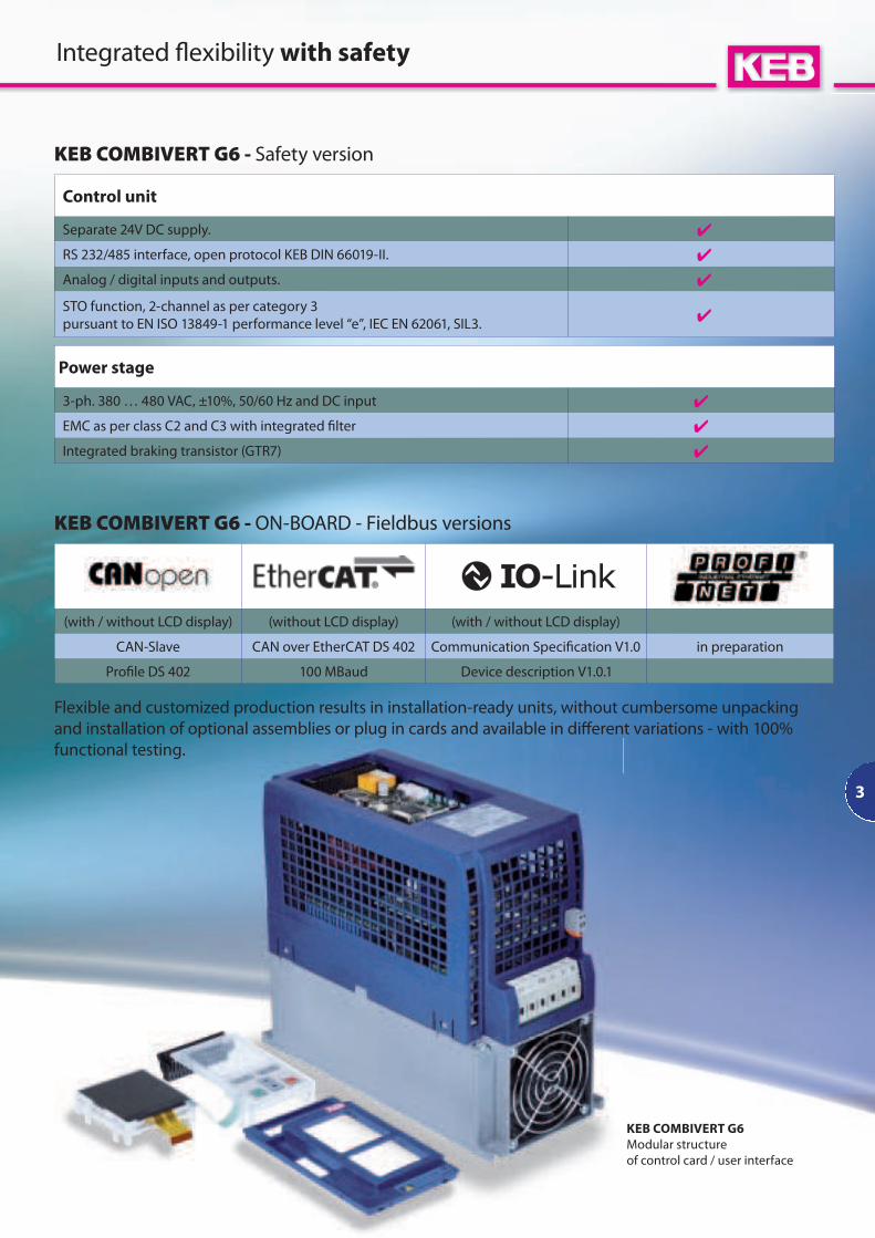
Flexible and customized production results in installation-ready units, without cumbersome unpacking
and installation of optional assemblies or plug in cards and available in di% erent variations - with 100%
functional testing.
KEB COMBIVERT G6 - ON-BOARD - Fieldbus versions
(with / without LCD display) (without LCD display) (with / without LCD display)
CAN-Slave CAN over EtherCAT DS 402 Communication Speci$ cation V1.0 in preparation
Pro$ le DS 402 100 MBaud Device description V1.0.1
Control unit
Separate 24V DC supply.
RS 232/485 interface, open protocol KEB DIN 66019-II.
Analog / digital inputs and outputs.
STO function, 2-channel as per category 3
pursuant to EN ISO 13849-1 performance level “e”, IEC EN 62061, SIL3.
Power stage
3-ph. 380 … 480 VAC, ±10%, 50/60 Hz and DC input
EMC as per class C2 and C3 with integrated $ lter
Integrated braking transistor (GTR7)
KEB COMBIVERT G6 - Safety version
KEB COMBIVERT G6
Modular structure
of control card / user interface
4
OEM - User guide
n for direct use in series equipment, KEB o% ers
the option of delivering devices ex works,
which are fully preset and protected against
unauthorised access with a password.
Quick input/output scanning
n for the 32-pole control clamp, such as for
dynamic start-stop applications with high and
reproducible repeat accuracy of the movement
pro$ le.
Digital inputs and outputs
n 8 Digital In
2 Digital Out
2 relays
Universal analog inputs / outputs
n 2 Analog In
set values 0 … ±10 V, 0 … ±20 mA, 4 … 20 mA
2 Analog Out (0 … ±10 V)
8 Parameter sets
n with complete set programming o% er extensive
internal functionality for I/O handling tasks
or sequential operation of multiple motors,
and can also partially take over otherwise
superordinated PLC tasks.
PID controllers
n process controllers for processing internal and
external variables.
Brake control
n special parameters for controlling brake motors
and the safe operation of sliding-rotor motors.
DC-braking
n for stopping drives without brake resistance by
absorbing the movement energy in the motor.
No-Safety-Version
n on request:
available without integrated safety function.
No-Display-Version
n devices without LCD displays and keyboard
are available for series use with serial
communication and for users with only PC
operation.
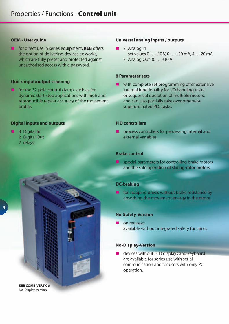
Properties / Functions - Control unit
KEB COMBIVERT G6
No-Display-Version
5
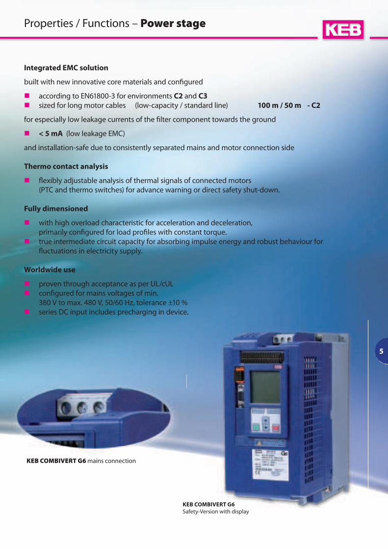
KEB COMBIVERT G6 mains connection
Integrated EMC solution
built with new innovative core materials and con$ gured
n according to EN61800-3 for environments C2 and C3
n sized for long motor cables (low-capacity / standard line) 100 m / 50 m - C2
for especially low leakage currents of the $ lter component towards the ground
n < 5 mA (low leakage EMC)
and installation-safe due to consistently separated mains and motor connection side
Thermo contact analysis
n # exibly adjustable analysis of thermal signals of connected motors
(PTC and thermo switches) for advance warning or direct safety shut-down.
Fully dimensioned
n with high overload characteristic for acceleration and deceleration,
primarily con$ gured for load pro$ les with constant torque.
n true intermediate circuit capacity for absorbing impulse energy and robust behaviour for
# uctuations in electricity supply.
Worldwide use
n proven through acceptance as per UL/cUL
n con$ gured for mains voltages of min.
380 V to max. 480 V, 50/60 Hz, tolerance ±10 %
n series DC input includes precharging in device.
Properties / Functions – Power stage
KEB COMBIVERT G6
Safety-Version with display
6
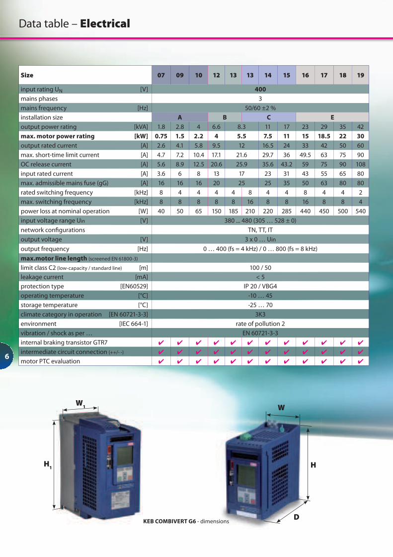
Size 07 09 10 12 13 13 14 15 16 17 18 19
input rating UN [V] 400
mains phases 3
mains frequency [Hz] 50/60 ±2 %
installation size A B C E
output power rating [kVA] 1.8 2.8 4 6.6 8.3 11 17 23 29 35 42
max. motor power rating [kW] 0.75 1.5 2.2 4 5.5 7.5 11 15 18.5 22 30
output rated current [A] 2.6 4.1 5.8 9.5 12 16.5 24 33 42 50 60
max. short-time limit current [A] 4.7 7.2 10.4 17.1 21.6 29.7 36 49.5 63 75 90
OC release current [A] 5.6 8.9 12.5 20.6 25.9 35.6 43.2 59 75 90 108
input rated current [A] 3.6 6 8 13 17 23 31 43 55 65 80
max. admissible mains fuse (gG) [A] 16 16 16 20 25 25 35 50 63 80 80
rated switching frequency [kHz] 8 4 4 4 4 8 4 4 8 4 4 2
max. switching frequency [kHz] 8 8 8 8 8 16 8 8 16 8 8 4
power loss at nominal operation [W] 40 50 65 150 185 210 220 285 440 450 500 540
input voltage range Uin [V] 380 ... 480 (305 … 528 ± 0)
network con$ gurations TN, TT, IT
output voltage [V] 3 x 0 … Uin
output frequency [Hz] 0 … 400 (fs = 4 kHz) / 0 … 800 (fs = 8 kHz)
max.motor line length (screened EN 61800-3)
limit class C2 (low-capacity / standard line) [m] 100 / 50
leakage current [mA] < 5
protection type [EN60529] IP 20 / VBG4
operating temperature [°C] -10 … 45
storage temperature [°C] -25 … 70
climate category in operation [EN 60721-3-3] 3K3
environment [IEC 664-1] rate of pollution 2
vibration / shock as per … EN 60721-3-3
internal braking transistor GTR7
intermediate circuit connection (++/- -)
motor PTC evaluation
Data table – Electrical
W1
H1
W
H
DKEB COMBIVERT G6 - dimensions
7
Gx xx x6. . –x x3 x x
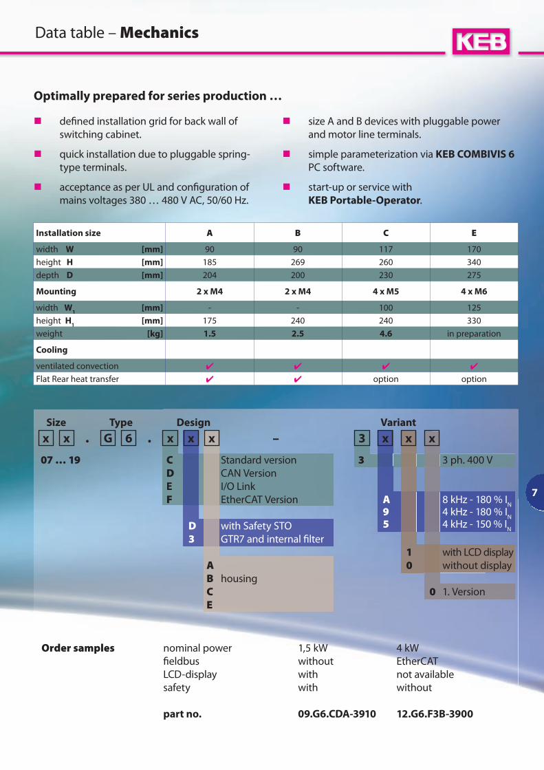
Optimally prepared for series production …
Data table – Mechanics
Installation size A B C E
width W [mm] 90 90 117 170
height H [mm] 185 269 260 340
depth D [mm] 204 200 230 275
Mounting 2 x M4 2 x M4 4 x M5 4 x M6
width W1
[mm] - - 100 125
height H1
[mm] 175 240 240 330
weight [kg] 1.5 2.5 4.6 in preparation
Cooling
ventilated convection
Flat Rear heat transfer option option
Size Type Design Variant
07 … 19 C Standard version 3 3 ph. 400 V
D CAN Version
E I/O Link
F EtherCAT Version A 8 kHz - 180 % IN
9 4 kHz - 180 % IN
D with Safety STO 5 4 kHz - 150 % IN
3 GTR7 and internal $ lter
1 with LCD display
A 0 without display
B housing
C 0 1. Version
E
Order samples nominal power 1,5 kW 4 kW
$ eldbus without EtherCAT
LCD-display with not available
safety with without
part no. 09.G6.CDA-3910 12.G6.F3B-3900
n de$ ned installation grid for back wall of
switching cabinet.
n quick installation due to pluggable spring-
type terminals.
n acceptance as per UL and con$ guration of
mains voltages 380 … 480 V AC, 50/60 Hz.
n size A and B devices with pluggable power
and motor line terminals.
n simple parameterization via KEB COMBIVIS 6
PC software.
n start-up or service with
KEB Portable-Operator.
8
Food production
n high breakaway torque during start-up
n exact torque during process
Packaging technology
n fast set value processing at ±10 V
n controlled positioning compensates dead times
Conveyor and storage technology
n long motor lines up to 100 m
n robust mechanics
Cranes, lifting devices
n high dynamics during acceleration
n internal braking transistor
Compressors
n output frequency up to 800 Hz
n PID controllers for process control
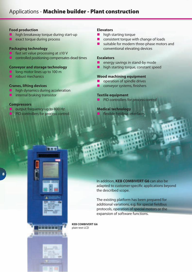
In addition, KEB COMBIVERT G6 can also be
adapted to customer-speci$ c applications beyond
the described scope.
The existing platform has been prepared for
additional variations, e.g. for special $ eldbus
protocols, operation of special motors or the
expansion of software functions.
Applications - Machine builder - Plant construction
KEB COMBIVERT G6
plain text LCD
Elevators
n high starting torque
n consistent torque with change of loads
n suitable for modern three-phase motors and
conventional elevating devices
Escalators
n energy savings in stand-by mode
n high starting torque, constant speed
Wood machining equipment
n operation of spindle drives
n conveyor systems, $ nishers
Textile equipment
n PID controllers for process control
Medical technology
n # exible $ eldbus interfaces
9
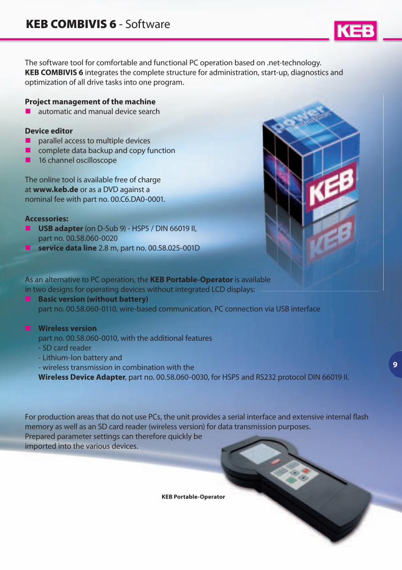
The software tool for comfortable and functional PC operation based on .net-technology.
KEB COMBIVIS 6 integrates the complete structure for administration, start-up, diagnostics and
optimization of all drive tasks into one program.
Project management of the machine
n automatic and manual device search
Device editor
n parallel access to multiple devices
n complete data backup and copy function
n 16 channel oscilloscope
The online tool is available free of charge
at www.keb.de or as a DVD against a
nominal fee with part no. 00.C6.DA0-0001.
Accessories:
n USB adapter (on D-Sub 9) - HSP5 / DIN 66019 II,
part no. 00.58.060-0020
n service data line 2.8 m, part no. 00.58.025-001D
KEB COMBIVIS 6 - Software
As an alternative to PC operation, the KEB Portable-Operator is available
in two designs for operating devices without integrated LCD displays:
n Basic version (without battery)
part no. 00.58.060-0110, wire-based communication, PC connection via USB interface
n Wireless version
part no. 00.58.060-0010, with the additional features
- SD card reader
- Lithium-Ion battery and
- wireless transmission in combination with the
Wireless Device Adapter, part no. 00.58.060-0030, for HSP5 and RS232 protocol DIN 66019 II.
For production areas that do not use PCs, the unit provides a serial interface and extensive internal # ash
memory as well as an SD card reader (wireless version) for data transmission purposes.
Prepared parameter settings can therefore quickly be
imported into the various devices.
KEB Portable-Operator
10
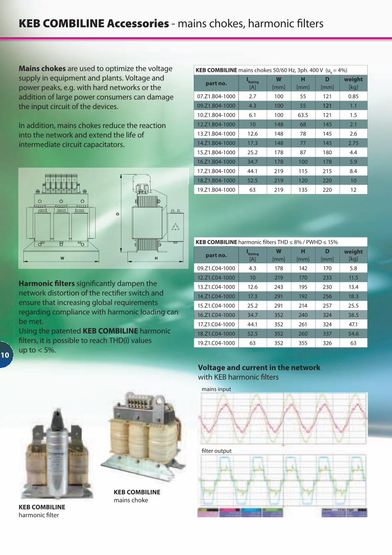
Mains chokes are used to optimize the voltage
supply in equipment and plants. Voltage and
power peaks, e.g. with hard networks or the
addition of large power consumers can damage
the input circuit of the devices.
In addition, mains chokes reduce the reaction
into the network and extend the life of
intermediate circuit capacitators.
KEB COMBILINE Accessories - mains chokes, harmonic $ lters
Harmonic " lters signi$ cantly dampen the
network distortion of the recti$ er switch and
ensure that increasing global requirements
regarding compliance with harmonic loading can
be met.
Using the patented KEB COMBILINE harmonic
$ lters, it is possible to reach THD(i) values
up to < 5%.
KEB COMBILINE
harmonic $ lter
mains input
$ lter output
KEB COMBILINE
mains choke
KEB COMBILINE mains chokes 50/60 Hz, 3ph. 400 V (uK
= 4%)
part no.I
Rating
[A]
W
[mm]
H
[mm]
D
[mm]
weight
[kg]
07.Z1.B04-1000 2.7 100 55 121 0.85
09.Z1.B04-1000 4.3 100 55 121 1.1
10.Z1.B04-1000 6.1 100 63.5 121 1.5
12.Z1.B04-1000 10 148 68 145 2.1
13.Z1.B04-1000 12.6 148 78 145 2.6
14.Z1.B04-1000 17.3 148 77 145 2.75
15.Z1.B04-1000 25.2 178 87 180 4.4
16.Z1.B04-1000 34.7 178 100 178 5.9
17.Z1.B04-1000 44.1 219 115 215 8.4
18.Z1.B04-1000 52.5 219 120 220 10
19.Z1.B04-1000 63 219 135 220 12
KEB COMBILINE harmonic $ lters THD ≤ 8% / PWHD ≤ 15%
part no.I
Rating
[A]
W
[mm]
H
[mm]
D
[mm]
weight
[kg]
09.Z1.C04-1000 4.3 178 142 170 5.8
12.Z1.C04-1000 10 219 170 233 11.5
13.Z1.C04-1000 12.6 243 195 230 13.4
14.Z1.C04-1000 17.3 291 192 256 18.3
15.Z1.C04-1000 25.2 291 214 257 25.5
16.Z1.C04-1000 34.7 352 240 324 38.5
17.Z1.C04-1000 44.1 352 261 324 47.1
18.Z1.C04-1000 52.5 352 260 337 54.6
19.Z1.C04-1000 63 352 355 326 63
Voltage and current in the network
with KEB harmonic $ lters
W H
D
11
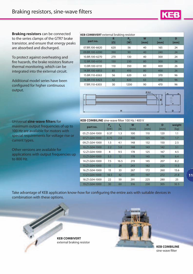
KEB COMBILINE sine-wave $ lter 100 Hz / 400 V
part no.P
N
[kW]
IN
[A]
W
[mm]
H
[mm]
D
[mm]
weight
[kg]
05.Z1.G04-1000 0.37 1.3 100 110 120 1.1
07.Z1.G04-1000 0.75 2.6 100 125 135 1.7
09.Z1.G04-1000 1.5 4.1 148 132 150 2.5
10.Z1.G04-1000 2.2 5.8 148 143 142 3.1
12.Z1.G04-1000 4 9.5 178 125 167 4.5
13.Z1.G04-1000 5.5 12 178 145 178 6.4
14.Z1.G04-1000 7.5 16.5 219 145 207 8.2
15.Z1.G04-1000 11 24 243 182 225 11.5
16.Z1.G04-1000 15 33 267 172 260 15.6
17.Z1.G04-1000 18.5 42 291 197 272 21.8
18.Z1.G04-1000 22 50 291 225 280 25
19.Z1.G04-1000 30 60 316 230 305 32.5
Braking resistors, sine-wave $ lters
Braking resistors can be connected
to the series clamps of the GTR7 brake
transistor, and ensure that energy peaks
are absorbed and discharged.
To protect against overheating and
$ re hazards, the brake resistors feature
thermal monitoring, which can be
integrated into the external circuit.
Additional model series have been
con$ gured for higher continuous
output.
Universal sine-wave " lters for
maximum output frequencies of up to
100 Hz are available for motors with
special requirements for voltage rise or
current types.
Other versions are available for
applications with output frequencies up
to 800 Hz.
Take advantage of KEB application know-how for con$ guring the entire axis with suitable devices in
combination with these options.
KEB COMBIVERT external braking resistor
part no.R
[Ω]
PD
[W]
W
[mm]
H
[mm]
D
[mm]
07.BR.100-6620 620 56 40 165 24
09.BR.100-6390 390 90 40 240 24
10.BR.100-6270 270 130 40 300 24
12.BR.100-6150 150 230 80 300 26
13.BR.100-6110 110 350 80 400 26
14.BR.100-6853 85 410 80 400 26
15.BR.110-6563 56 620 63 370 96
16.BR.110-6423 42 820 63 470 96
17.BR.110-6303 30 1200 90 470 96
KEB COMBIVERT
external braking resistor
KEB COMBILINE
sine-wave $ lter