Embed Size (px)
Citation preview
MACRO-MODELING AND ENERGY EFFICIENCY STUDIES OF FILE
MANAGEMENT IN EMBEDDED SYSTEMS WITH FLASH MEMORY
A Thesis
by
NITESH GOYAL
Submitted to the Office of Graduate Studies ofTexas A&M University
in partial fulfillment of the requirements for the degree of
MASTER OF SCIENCE
May 2005
Major Subject: Computer Science
MACRO-MODELING AND ENERGY EFFICIENCY STUDIES OF FILE
MANAGEMENT IN EMBEDDED SYSTEMS WITH FLASH MEMORY
A Thesis
by
NITESH GOYAL
Submitted to Texas A&M Universityin partial fulfillment of the requirements
for the degree of
MASTER OF SCIENCE
Approved as to style and content by:
Rabi Mahapatra(Chair of Committee)
Riccardo Bettati(Member)
Deepa Kundur(Member)
Valerie E. Taylor(Head of Department)
May 2005
Major Subject: Computer Science
iii
ABSTRACT
Macro-modeling and Energy Efficiency Studies of File Management in Embedded
Systems with Flash Memory. (May 2005)
Nitesh Goyal, B.S., The University of Texas at Austin
Chair of Advisory Committee: Dr. Rabi Mahaptra
Technological advancements in computer hardware and software have made embedded
systems highly affordable and widely used. Consumers have ever increasing demands
for powerful embedded devices such as cell phones, PDAs and media players. Such
complex and feature-rich embedded devices are strictly limited by their battery life-
time. Embedded systems typically are diskless and use flash for secondary storage
due to their low power, persistent storage and small form factor needs. The energy
efficiency of a processor and flash in an embedded system heavily depends on the
choice of file system in use. To address this problem, it is necessary to provide sys-
tem developers with energy profiles of file system activities and energy efficient file
systems. In the first part of the thesis, a macro-model for the CRAMFS file system
is established which characterizes the processor and flash energy consumption due to
file system calls. This macro-model allows a system developer to estimate the energy
consumed by CRAMFS without using an actual power setup. The second part of
the thesis examines the effects of using non-volatile memory as a write-behind buffer
to improve the energy efficiency of JFFS2. Experimental results show that a 4KB
write-behind buffer significantly reduces energy consumption by up to 2-3 times for
consecutive small writes. In addition, the write-behind buffer conserves flash space
since transient data may never be written to flash.
iv
To my Parents

v
ACKNOWLEDGMENTS
I thank Dr. Rabi Mahapatra for guiding me in my research. I am grateful to him for
letting me take up this interesting work.
I would like to thank Siddharth for introducing me to Linux hacking and embed-
ded systems.
I have had an enjoyable and memorable time working in the Codesign group. I
wish to thank Praveen, Junyi, Purna, Subrata and Jason for the enjoyable discussions
I had with them.
I would like to thank Dr. Kundur and Dr. Bettati for serving on my committee
and taking time to help me with this thesis.
Finally, I would like to thank my parents and sister for their encouragement and
unconditional love.
vi
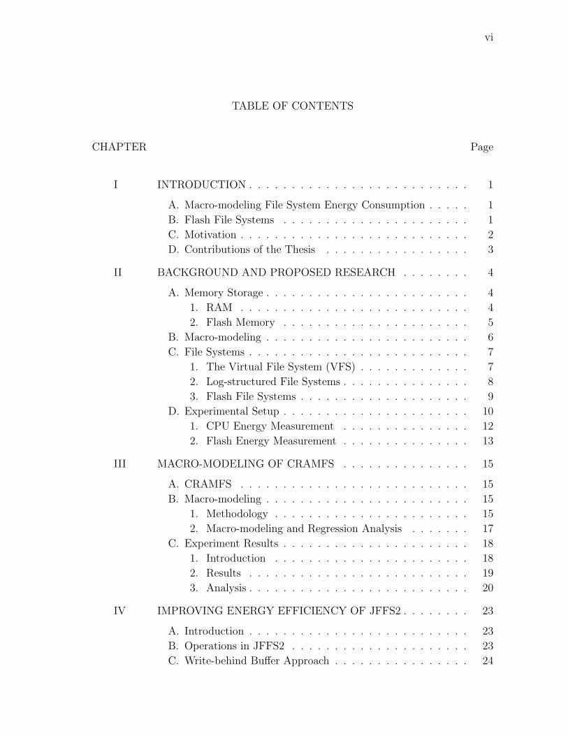
TABLE OF CONTENTS
CHAPTER Page
I INTRODUCTION . . . . . . . . . . . . . . . . . . . . . . . . . . 1
A. Macro-modeling File System Energy Consumption . . . . . 1
B. Flash File Systems . . . . . . . . . . . . . . . . . . . . . . 1
C. Motivation . . . . . . . . . . . . . . . . . . . . . . . . . . . 2
D. Contributions of the Thesis . . . . . . . . . . . . . . . . . 3
II BACKGROUND AND PROPOSED RESEARCH . . . . . . . . 4
A. Memory Storage . . . . . . . . . . . . . . . . . . . . . . . . 4
1. RAM . . . . . . . . . . . . . . . . . . . . . . . . . . . 4
2. Flash Memory . . . . . . . . . . . . . . . . . . . . . . 5
B. Macro-modeling . . . . . . . . . . . . . . . . . . . . . . . . 6
C. File Systems . . . . . . . . . . . . . . . . . . . . . . . . . . 7
1. The Virtual File System (VFS) . . . . . . . . . . . . . 7
2. Log-structured File Systems . . . . . . . . . . . . . . . 8
3. Flash File Systems . . . . . . . . . . . . . . . . . . . . 9
D. Experimental Setup . . . . . . . . . . . . . . . . . . . . . . 10
1. CPU Energy Measurement . . . . . . . . . . . . . . . 12
2. Flash Energy Measurement . . . . . . . . . . . . . . . 13
III MACRO-MODELING OF CRAMFS . . . . . . . . . . . . . . . 15
A. CRAMFS . . . . . . . . . . . . . . . . . . . . . . . . . . . 15
B. Macro-modeling . . . . . . . . . . . . . . . . . . . . . . . . 15
1. Methodology . . . . . . . . . . . . . . . . . . . . . . . 15
2. Macro-modeling and Regression Analysis . . . . . . . 17
C. Experiment Results . . . . . . . . . . . . . . . . . . . . . . 18
1. Introduction . . . . . . . . . . . . . . . . . . . . . . . 18
2. Results . . . . . . . . . . . . . . . . . . . . . . . . . . 19
3. Analysis . . . . . . . . . . . . . . . . . . . . . . . . . . 20
IV IMPROVING ENERGY EFFICIENCY OF JFFS2 . . . . . . . . 23
A. Introduction . . . . . . . . . . . . . . . . . . . . . . . . . . 23
B. Operations in JFFS2 . . . . . . . . . . . . . . . . . . . . . 23
C. Write-behind Buffer Approach . . . . . . . . . . . . . . . . 24
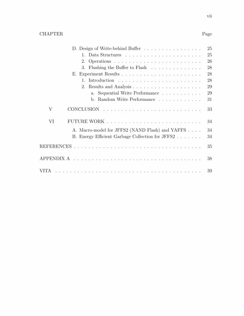
vii
CHAPTER Page
D. Design of Write-behind Buffer . . . . . . . . . . . . . . . . 25
1. Data Structures . . . . . . . . . . . . . . . . . . . . . 25
2. Operations . . . . . . . . . . . . . . . . . . . . . . . . 26
3. Flushing the Buffer to Flash . . . . . . . . . . . . . . 28
E. Experiment Results . . . . . . . . . . . . . . . . . . . . . . 28
1. Introduction . . . . . . . . . . . . . . . . . . . . . . . 28
2. Results and Analysis . . . . . . . . . . . . . . . . . . . 29
a. Sequential Write Performance . . . . . . . . . . . 29
b. Random Write Performance . . . . . . . . . . . . 31
V CONCLUSION . . . . . . . . . . . . . . . . . . . . . . . . . . . 33
VI FUTURE WORK . . . . . . . . . . . . . . . . . . . . . . . . . . 34
A. Macro-model for JFFS2 (NAND Flash) and YAFFS . . . . 34
B. Energy Efficient Garbage Collection for JFFS2 . . . . . . . 34
REFERENCES . . . . . . . . . . . . . . . . . . . . . . . . . . . . . . . . . . . 35
APPENDIX A . . . . . . . . . . . . . . . . . . . . . . . . . . . . . . . . . . . 38
VITA . . . . . . . . . . . . . . . . . . . . . . . . . . . . . . . . . . . . . . . . 39
viii
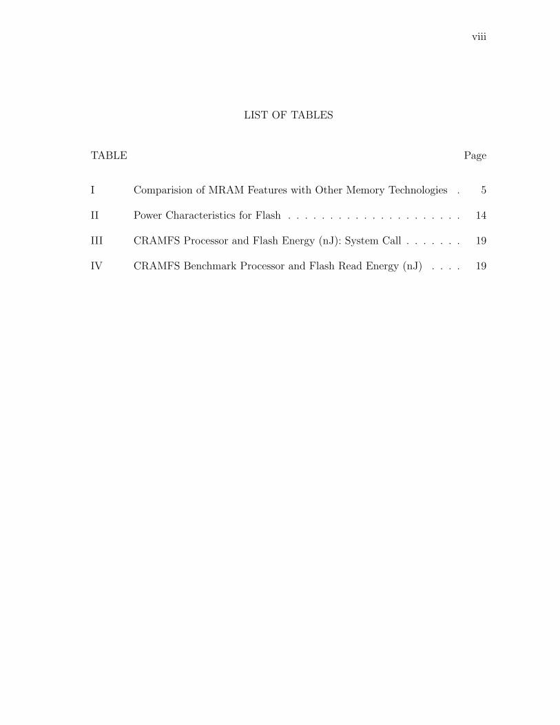
LIST OF TABLES
TABLE Page
I Comparision of MRAM Features with Other Memory Technologies . 5
II Power Characteristics for Flash . . . . . . . . . . . . . . . . . . . . . 14
III CRAMFS Processor and Flash Energy (nJ): System Call . . . . . . . 19
IV CRAMFS Benchmark Processor and Flash Read Energy (nJ) . . . . 19
ix
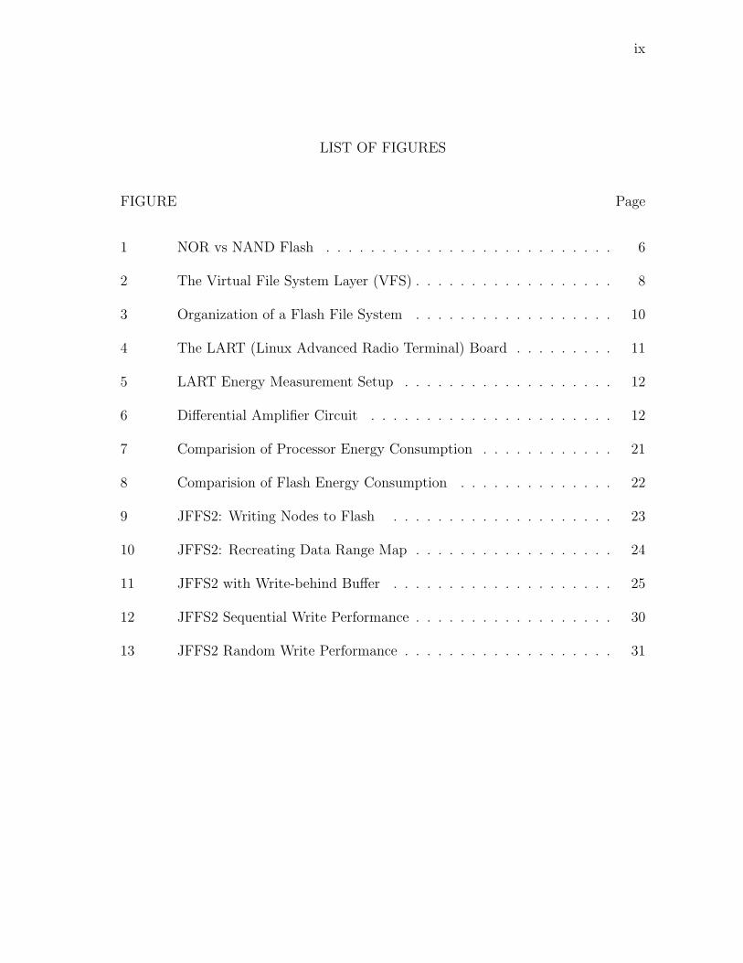
LIST OF FIGURES
FIGURE Page
1 NOR vs NAND Flash . . . . . . . . . . . . . . . . . . . . . . . . . . 6
2 The Virtual File System Layer (VFS) . . . . . . . . . . . . . . . . . . 8
3 Organization of a Flash File System . . . . . . . . . . . . . . . . . . 10
4 The LART (Linux Advanced Radio Terminal) Board . . . . . . . . . 11
5 LART Energy Measurement Setup . . . . . . . . . . . . . . . . . . . 12
6 Differential Amplifier Circuit . . . . . . . . . . . . . . . . . . . . . . 12
7 Comparision of Processor Energy Consumption . . . . . . . . . . . . 21
8 Comparision of Flash Energy Consumption . . . . . . . . . . . . . . 22
9 JFFS2: Writing Nodes to Flash . . . . . . . . . . . . . . . . . . . . 23
10 JFFS2: Recreating Data Range Map . . . . . . . . . . . . . . . . . . 24
11 JFFS2 with Write-behind Buffer . . . . . . . . . . . . . . . . . . . . 25
12 JFFS2 Sequential Write Performance . . . . . . . . . . . . . . . . . . 30
13 JFFS2 Random Write Performance . . . . . . . . . . . . . . . . . . . 31
1
CHAPTER I
INTRODUCTION
Technological advancements in computer hardware and software have made embed-
ded systems highly affordable and widely used. Most embedded systems are strictly
limited by their battery lifetime. Embedded systems usually do not use disk drives
for secondary storage since disk drives have high power [1] and space requirements
and a low tolerance for movement compared to flash memory. As a result, embedded
systems typically use flash for secondary storage due to their low power, persistent
storage and small form factor needs [2].
A. Macro-modeling File System Energy Consumption
Macro-modeling is an estimation based technique that pre-characterizes a system and
provides a high level equation of the system. Such high level equations or models can
be used to estimate the power consumption of embedded file system operations with-
out using an actual power setup. Since embedded file systems use flash for secondary
storage, an accurate macro-model for a file system would have to characterize energy
consumption due to the CPU and flash separately. Such a macro-model could be de-
veloped by running file system operations on different file sizes and using regression
analysis to formulate a macro-model.
B. Flash File Systems
Conventional block based file systems such as EXT2 do not efficiently use flash due to
various limitations of flash. Writes to flash need to be preceded by erasing the whole
The journal model is IEEE Transactions on Automatic Control.

2
eraseblock. Since block based file systems read/write 512 byte sectors at a time,
writing to flash would require reading the eraseblock containing the 512 byte sector,
modifying it in memory, erasing the eraseblock and finally writing the in-memory
copy to flash. Additionally, eraseblocks in flash can be erased only a limited number
of times (< 100,000). To mitigate such issues, flash file systems such as JFFS2 [3] and
YAFFS [4] have been developed which directly operate on flash rather than writing
indirectly to flash. JFFS2 and YAFFS also perform wear-leveling to ensure that
eraseblocks are evenly used and thus prevent the premature flash failure.
C. Motivation
The energy efficiency of a processor and flash in an embedded system heavily de-
pends on the choice of file system in use. The energy consumption of the file system
indicates the longevity of battery life in an embedded system. It is thus necessary
to provide embedded system developers with energy efficient file systems and energy
consumption profiles of such file systems.
Due to fast time to market, embedded system developers do not have the time or
experimental setup to measure the energy consumption of file system related activi-
ties. Macro-modeling a file system allows an embedded system developer to select an
appropriate file system based on his/her power budget. The first goal of this thesis
is to develop a macro-model for CRAMFS.
The macro-model developed in [5] for JFFS2 highlights that writes consume
the most energy compared to other file system operations. Improving the energy
efficiency of writes would directly help improve the overall energy efficiency of JFFS2.
Currently, JFFS2 writes synchronously to flash due to reliability issues. However,
with promising technological advancements in persistent RAM technologies such as
3
MRAM [6], embedded systems could soon economically use small sizes of MRAM. A
write-behind buffer could be developed which would enable asynchronous writes to
flash, yet maintaining reliability provided by synchronous writes. The second goal of
this thesis is to examine the effects of using non-volatile memory such as MRAM as
a write-behind buffer to improve the energy efficiency of JFFS2.
D. Contributions of the Thesis
1. In the first part of the thesis, we improve the macro-model developed in [5] by
developing a macro-model for the read-only CRAMFS file system [7]. Various
sytem calls such as read, open and close are macro-modeled.
2. We also compare and contrast the file read operation of CRAMFS with the ex-
isting file systems in the macro-model developed in [5]. Such a study highlights
the advantages of using CRAMFS over JFFS2 ands EXT3 for read-only file
system partitions.
3. In the second part of the thesis, we examine the effects of using non-volatile
memory as a write-behind buffer to improve the energy efficiency of JFFS2.
Experimental results show that a 4KB write-behind buffer significantly reduces
energy consumption for consecutive small writes. In addition, the write-behind
buffer conserves flash space since transient data may never be written to flash.
4
CHAPTER II
BACKGROUND AND PROPOSED RESEARCH
A. Memory Storage
1. RAM
Embedded systems typically use DRAM for primary memory storage. DRAM does
not contain batteries, and instead draws its power from the processor’s power supply
unit. In the event of a power loss, all data stored in DRAM can be lost. Therefore,
embedded systems typically use flash or hard drives for secondary memory storage.
Although flash provides excellent read performance, its write performance is very
slow.
Battery-backed DRAM provides excellent read and write performance but its
reliability is short lived for a few hours. SRAM, backed by on-board batteries (which
can last to up to a year) provides longer lasting persistence memory storage. Although
more expensive than DRAM and flash, it is economical to contain small sizes of SRAM
(< 100 KB) to store write buffers. Recently, magnetic RAM (MRAM) [8] is seen as
a promising emerging persistent RAM technology. MRAM chips use magnetic rather
than electric structures to store data, thus not requiring constant power and periodic
refreshing like DRAM. MRAM [6] compared to DRAM, is expected to drastically
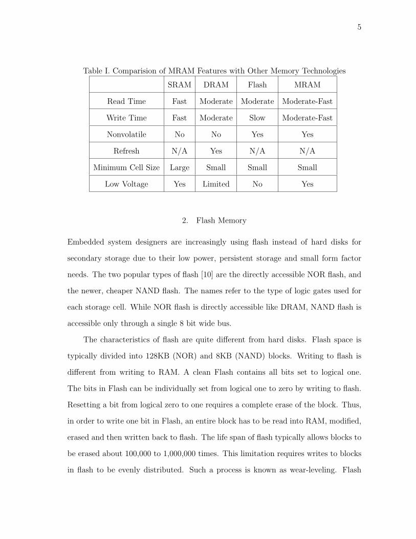
reduce the energy consumption of emebedded devices. Table I [6] compares the
expected features of MRAM with other memory technologies.
Various companies such as IBM [9] and Freescale Semiconductor [6] plan to
release MRAM chips in the near future.
5
Table I. Comparision of MRAM Features with Other Memory Technologies
SRAM DRAM Flash MRAM
Read Time Fast Moderate Moderate Moderate-Fast
Write Time Fast Moderate Slow Moderate-Fast
Nonvolatile No No Yes Yes
Refresh N/A Yes N/A N/A
Minimum Cell Size Large Small Small Small
Low Voltage Yes Limited No Yes
2. Flash Memory
Embedded system designers are increasingly using flash instead of hard disks for
secondary storage due to their low power, persistent storage and small form factor
needs. The two popular types of flash [10] are the directly accessible NOR flash, and
the newer, cheaper NAND flash. The names refer to the type of logic gates used for
each storage cell. While NOR flash is directly accessible like DRAM, NAND flash is
accessible only through a single 8 bit wide bus.
The characteristics of flash are quite different from hard disks. Flash space is
typically divided into 128KB (NOR) and 8KB (NAND) blocks. Writing to flash is
different from writing to RAM. A clean Flash contains all bits set to logical one.
The bits in Flash can be individually set from logical one to zero by writing to flash.
Resetting a bit from logical zero to one requires a complete erase of the block. Thus,
in order to write one bit in Flash, an entire block has to be read into RAM, modified,
erased and then written back to flash. The life span of flash typically allows blocks to
be erased about 100,000 to 1,000,000 times. This limitation requires writes to blocks
in flash to be evenly distributed. Such a process is known as wear-leveling. Flash
6
128 KB Block
.
.
.
.
.
.
.
.
.
128 KB Block
NOR
Flash
.
.
.
.
.
.
512 byte page
NANDFlash
8 KB Block
8 KB Block
Out of bound space
.
.
.
.
.
.
.
.
.
512 byte page
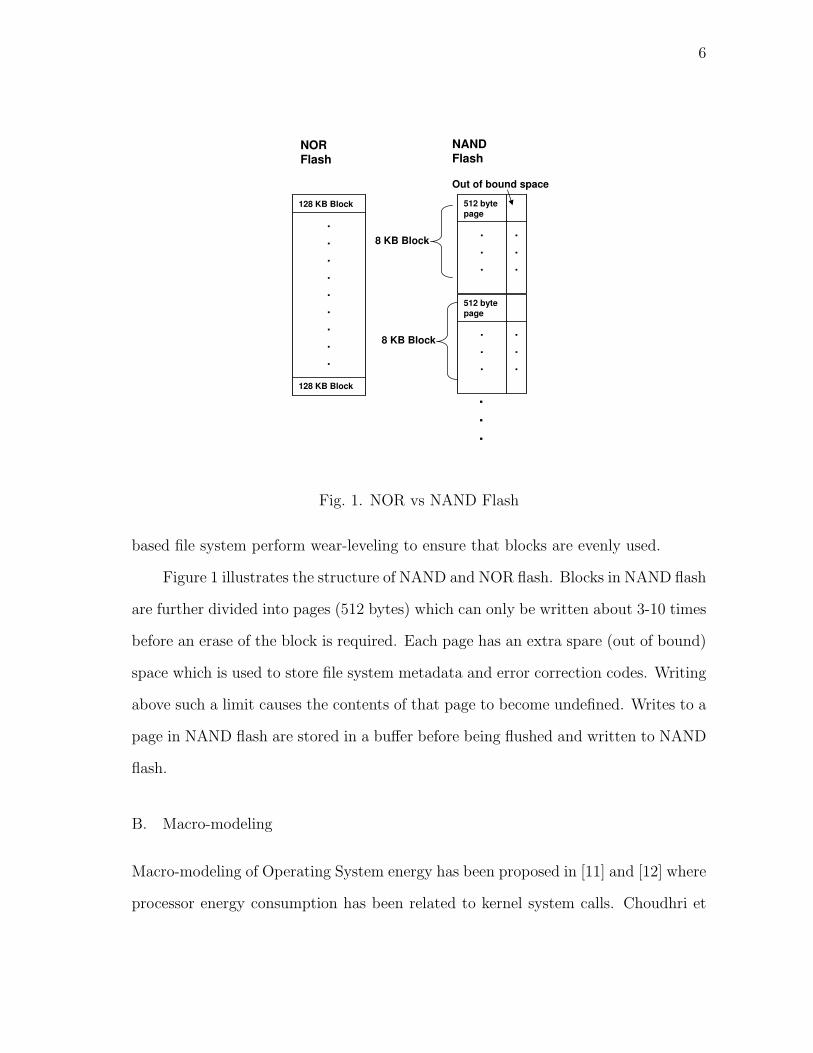
Fig. 1. NOR vs NAND Flash
based file system perform wear-leveling to ensure that blocks are evenly used.
Figure 1 illustrates the structure of NAND and NOR flash. Blocks in NAND flash
are further divided into pages (512 bytes) which can only be written about 3-10 times
before an erase of the block is required. Each page has an extra spare (out of bound)
space which is used to store file system metadata and error correction codes. Writing
above such a limit causes the contents of that page to become undefined. Writes to a
page in NAND flash are stored in a buffer before being flushed and written to NAND
flash.
B. Macro-modeling
Macro-modeling of Operating System energy has been proposed in [11] and [12] where
processor energy consumption has been related to kernel system calls. Choudhri et
7
al. [5] developed a macro-model for JFFS2 and EXT3 [13]. Their macro-model
characterizes file system energy consumption in terms of energy consumed by both
the processor and flash. In the first part of the thesis, we propose to develop a
macro-model for CRAMFS and compare its energy efficiency with JFFS2 and EXT3.
C. File Systems
A file system is part of the operating system which helps organize and manage files
and directories on a secondary storage device. It allows data to be stored, searched
and retrieved easily. JFFS2, YFFS, CRAMFS and RAMFS are some of the commonly
used file system in embedded systems.
1. The Virtual File System (VFS)
The VFS layer is an abstract file system layer used by Linux to provide a file system
interface to user space programs. The VFS layer helps decouple the user space pro-
grams from the actual file systems. As a result, Linux is able to support multiple file
systems such as EXT2/3, JFFS2 and CRAMFS. The VFS layer handles the generic
operations of a file system, such as caching file metadata and pages, error checking,
maintaining use of locks and communicating with the user space programs. On the
completion of the generic tasks, the VFS layer delegates the tasks to the lower level
file systems.
8
Virtual File System Layer (VFS)
User program 1 User program 2
Specific File System Layer (EXT2/3 ,JFFS2, CRAMFS)
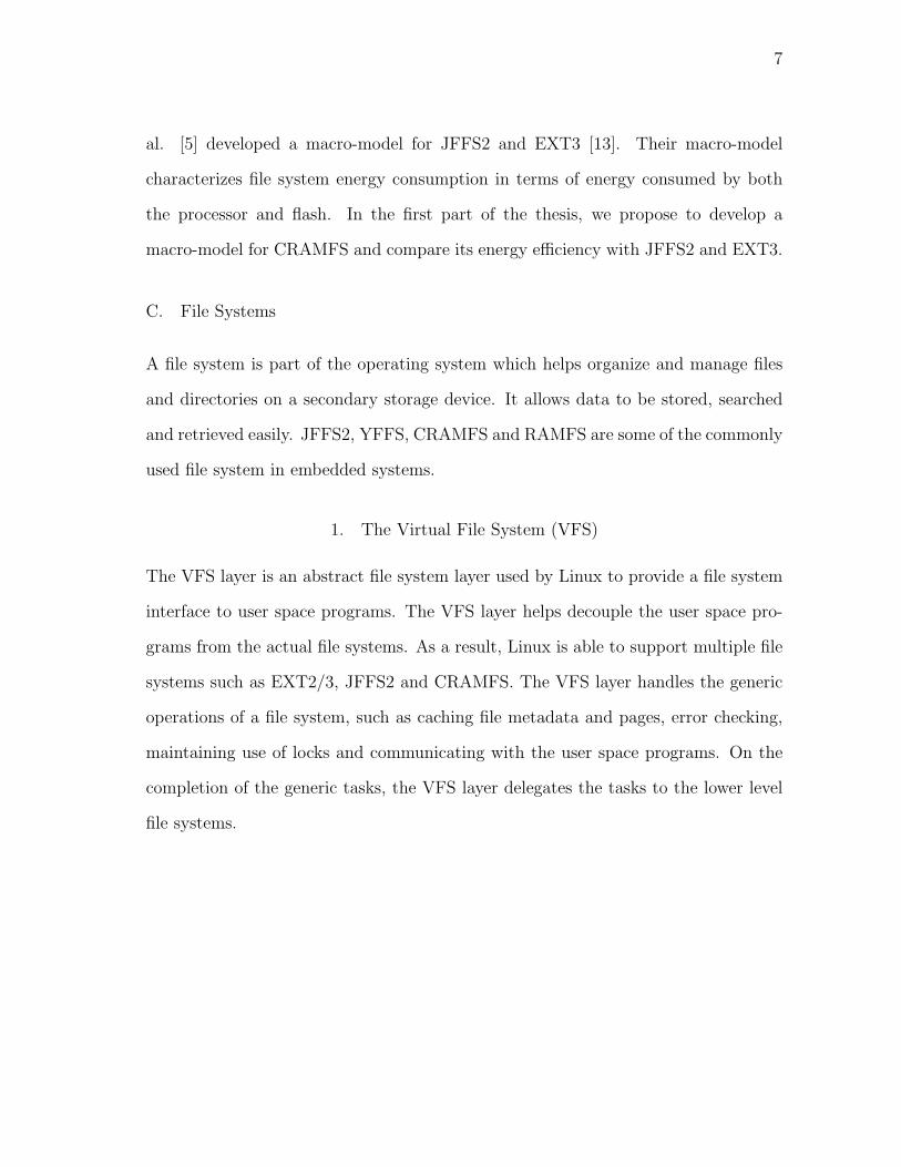
Fig. 2. The Virtual File System Layer (VFS)
Figure 2 illustrates the relation between the VFS and specific file system layer.
The VFS interface has a common file object model which consists of the following
objects:
1. Super block: stores data pertaining to the mounted file system.
2. Inode: stores meta-data for a single file, such as access and creation times, size,
owner, group and permissions. Files are identified using a unique inode number.
3. File: stores information about a file and the processes using it.
4. Dentry: maps a directory entry(file’s pathname) with its corresponding file
inode. The VFS caches the recently used dentry objects to speed up file lookup
operations.
2. Log-structured File Systems
The concept of a log structured file system was first introduced in Sprite LFS [14].
A log-structured file system logs changes of data and meta-data sequentially to the
storage medium. Sprite LFS dramatically improves write performance by eliminating
9
most seeks and aggregating writes into a cache before writing to disk. Due to its
sequential nature, Sprite LFS also permits faster crash recovery compared to con-
ventional file systems. Log-structured file systems are therefore ideal for embedded
devices since most embedded systems may shutdown anytime due to power losses and
erratic shutdowns by the user.
3. Flash File Systems
Several flash file systems have been developed which use flash as a storage medium.
Kawaguchi et al. [15] presented a flash translation layer that provides a 1:1 map-
ping between flash and an emulated block device. eNVY [16] uses a large amount
of flash as main memory and a small amount of battery backed SRAM for write
buffering. Microsoft Flash File System [17] provides MS-DOS compatibility with
flash medium. Chang et al. [18] proposed a tree based memory management scheme
for high capacity flash-memory based storage systems. The management scheme is
based on the behaviors of realistic access patterns. MRAMFS [19] is a non-volatile
RAM based file system which conserves space by compressing file meta-data and data
blocks in NVRAM. Dai et al. [20] proposed ELF, a log-structured flash based file
system tailored for sensor nodes. Since RAM is extremely scarce in sensor nodes,
ELF judiciously uses RAM and optimizes append writes by buffering writes into a
small buffer in RAM. Most file systems mentioned above use flash to emulate a block
device.These file systems use a virtual block layer to interface with the flash medium.
EXT3 and CRAMFS are examples of such a file system. Flash translation layers are
used to provide 1:1 mappings between flash and the emulated block device. Such an
approach is inefficient and and can cause improper wear-leveling.
10
Virtual File System (VFS)
JFFS2 YAFFS
CRAMFSEXT3
Linux Block Layer
Linux MTD Layer
NFTL mtdblock FTL
Block
DevicesFTL
NOR Flash NAND Flash RAM
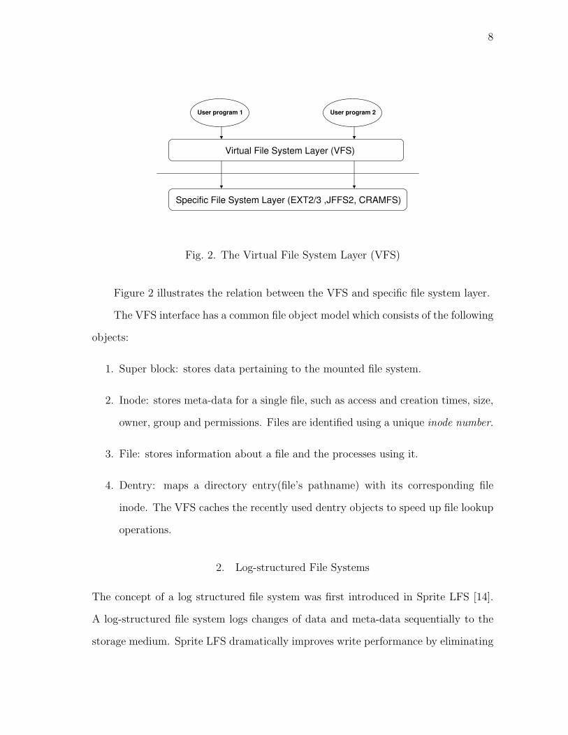
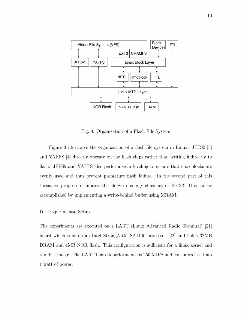
Fig. 3. Organization of a Flash File System
Figure 3 illustrates the organization of a flash file system in Linux. JFFS2 [3]
and YAFFS [4] directly operate on the flash chips rather than writing indirectly to
flash. JFFS2 and YAFFS also perform wear-leveling to ensure that eraseblocks are
evenly used and thus prevent premature flash failure. In the second part of this
thesis, we propose to improve the file write energy efficiency of JFFS2. This can be
accomplished by implementing a write-behind buffer using MRAM.
D. Experimental Setup
The experiments are executed on a LART (Linux Advanced Radio Terminal) [21]
board which runs on an Intel StrongARM SA1100 processor [22] and holds 32MB
DRAM and 4MB NOR flash. This configuration is sufficient for a linux kernel and
ramdisk image. The LART board’s performance is 250 MIPS and consumes less than
1 watt of power.
11
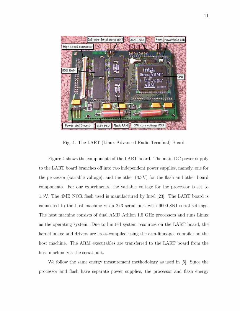
Fig. 4. The LART (Linux Advanced Radio Terminal) Board
Figure 4 shows the components of the LART board. The main DC power supply
to the LART board branches off into two independent power supplies, namely, one for
the processor (variable voltage), and the other (3.3V) for the flash and other board
components. For our experiments, the variable voltage for the processor is set to
1.5V. The 4MB NOR flash used is manufactured by Intel [23]. The LART board is
connected to the host machine via a 2x3 serial port with 9600-8N1 serial settings.
The host machine consists of dual AMD Athlon 1.5 GHz processors and runs Linux
as the operating system. Due to limited system resources on the LART board, the
kernel image and drivers are cross-compiled using the arm-linux-gcc compiler on the
host machine. The ARM executables are transferred to the LART board from the
host machine via the serial port.
We follow the same energy measurement methodology as used in [5]. Since the
processor and flash have separate power supplies, the processor and flash energy
12
LabView Console
Trigger
LART Board
SCB 68 connector
R2 = R3 = 1000KR1 = R4 = 1K
R1
R3
R2
R4
Vcpu
GND
PCI MIO
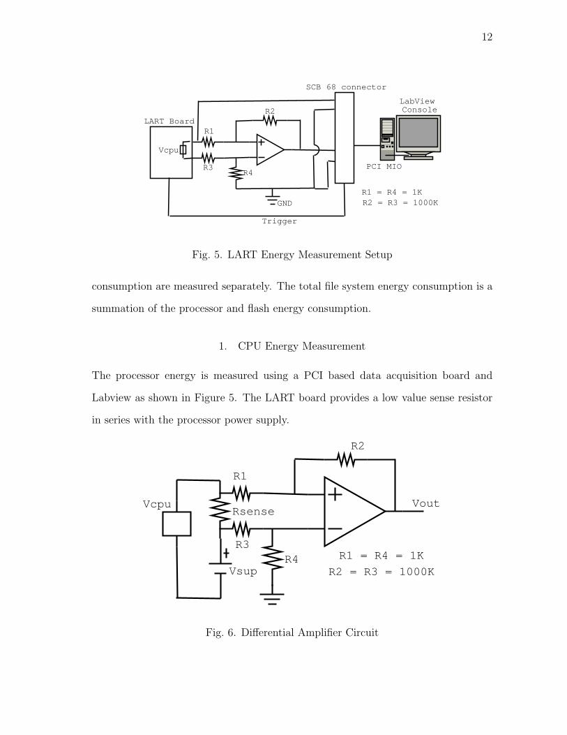
Fig. 5. LART Energy Measurement Setup
consumption are measured separately. The total file system energy consumption is a
summation of the processor and flash energy consumption.
1. CPU Energy Measurement
The processor energy is measured using a PCI based data acquisition board and
Labview as shown in Figure 5. The LART board provides a low value sense resistor
in series with the processor power supply.
R2
R1
R3R4
VoutVcpu
VsupR1 = R4 = 1K
R2 = R3 = 1000K
Rsense
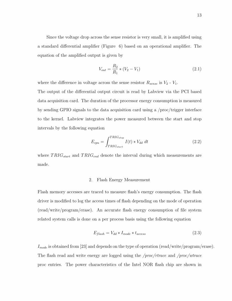
Fig. 6. Differential Amplifier Circuit
13
Since the voltage drop across the sense resistor is very small, it is amplified using
a standard differential amplifier (Figure 6) based on an operational amplifier. The
equation of the amplified output is given by
Vout =R2
R1
∗ (V2 − V1) (2.1)
where the difference in voltage across the sense resistor Rsense is V2 - V1.
The output of the differential output circuit is read by Labview via the PCI based
data acquisition card. The duration of the processor energy consumption is measured
by sending GPIO signals to the data acquisition card using a /proc/trigger interface
to the kernel. Labview integrates the power measured between the start and stop
intervals by the following equation
Ecpu =
∫ TRIGstop
TRIGstart
I(t) ∗ Vdd dt (2.2)
where TRIGstart and TRIGend denote the interval during which measurements are
made.
2. Flash Energy Measurement
Flash memory accesses are traced to measure flash’s energy consumption. The flash
driver is modified to log the access times of flash depending on the mode of operation
(read/write/program/erase). An accurate flash energy consumption of file system
related system calls is done on a per process basis using the following equation
Eflash = Vdd ∗ Imode ∗ taccess (2.3)
Imode is obtained from [23] and depends on the type of operation (read/write/program/erase).
The flash read and write energy are logged using the /proc/rtrace and /proc/wtrace
proc entries. The power characteristics of the Intel NOR flash chip are shown in
14
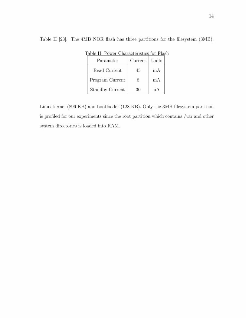
Table II [23]. The 4MB NOR flash has three partitions for the filesystem (3MB),
Table II. Power Characteristics for Flash
Parameter Current Units
Read Current 45 mA
Program Current 8 mA
Standby Current 30 uA
Linux kernel (896 KB) and bootloader (128 KB). Only the 3MB filesystem partition
is profiled for our experiments since the root partition which contains /var and other
system directories is loaded into RAM.
15
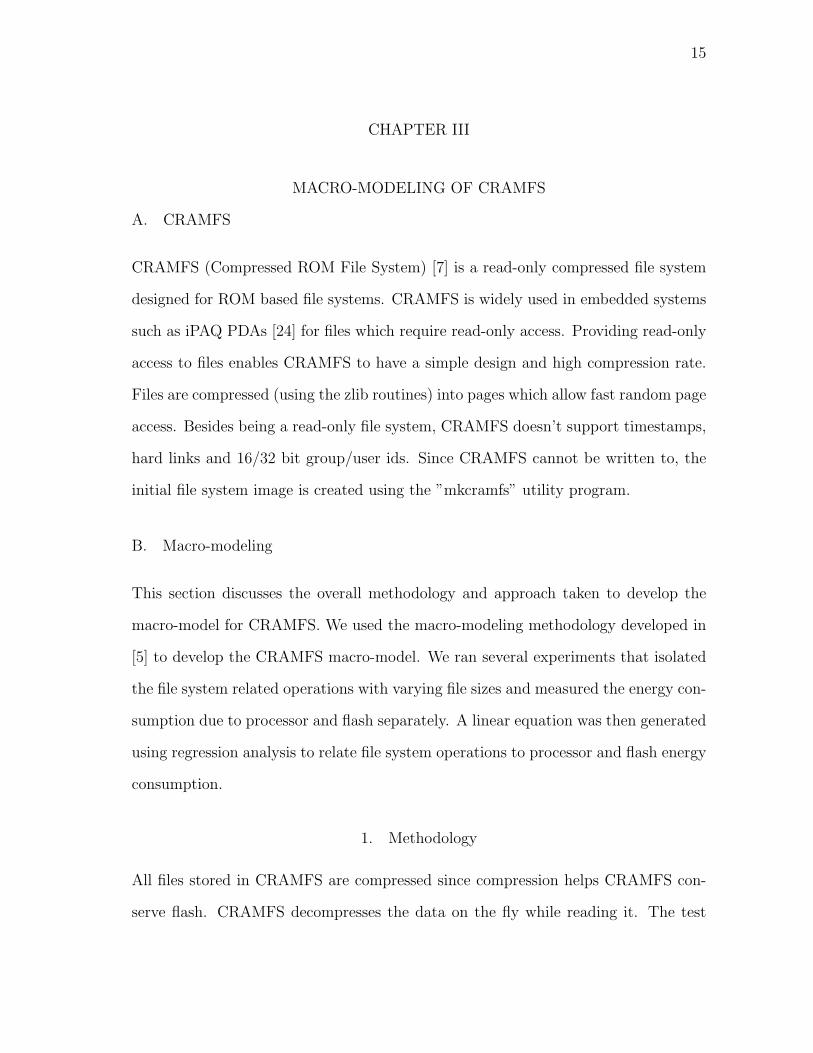
CHAPTER III
MACRO-MODELING OF CRAMFS
A. CRAMFS
CRAMFS (Compressed ROM File System) [7] is a read-only compressed file system
designed for ROM based file systems. CRAMFS is widely used in embedded systems
such as iPAQ PDAs [24] for files which require read-only access. Providing read-only
access to files enables CRAMFS to have a simple design and high compression rate.
Files are compressed (using the zlib routines) into pages which allow fast random page
access. Besides being a read-only file system, CRAMFS doesn’t support timestamps,
hard links and 16/32 bit group/user ids. Since CRAMFS cannot be written to, the
initial file system image is created using the ”mkcramfs” utility program.
B. Macro-modeling
This section discusses the overall methodology and approach taken to develop the
macro-model for CRAMFS. We used the macro-modeling methodology developed in
[5] to develop the CRAMFS macro-model. We ran several experiments that isolated
the file system related operations with varying file sizes and measured the energy con-
sumption due to processor and flash separately. A linear equation was then generated
using regression analysis to relate file system operations to processor and flash energy
consumption.
1. Methodology
All files stored in CRAMFS are compressed since compression helps CRAMFS con-
serve flash. CRAMFS decompresses the data on the fly while reading it. The test

16
programs used in all the file system operations, used files with random data in order
to formulate a macro-model with a worst case upper bound.
Reading data from a file is the most important file system operation since
CRAMFS is a read-only file system. The following steps were taken to formulate
a macro-model for the read system call:
1. A test program was written which reads data of a specific size from CRAMFS.
Triggers are sent to Labview to accurately start and stop the energy measure-
ment of the test program. After triggering Labview to start the energy measure-
ment, the test program starts reading data from twenty different files. Upon
completion of reading all twenty files, a trigger is again sent to Labview to stop
the energy measurement. Twenty files were read since the time required to read
one small file is too small to measure. The processor and flash energy consumed
for this read system call is divided by 20 to calculate the average.
2. Labview is used to measure the average processor energy consumption. The
average flash energy consumption is calculated by reading the bytes read from
flash using the /proc/rtrace proc entry. The rtrace proc entry stores the read
energy consumed by each process.
3. Steps 1 and 2 are repeated by varying the file size from 100 bytes to 1024 KB.
4. Having measured the processor and flash energy consumption for varying file
sizes, linear equations are calculated which relate the processor and flash energy
consumption to the varying file sizes.

17
2. Macro-modeling and Regression Analysis
A macro-model to calculate the processor and flash energy consumption in CRAMFS
is developed as follows:
Ecpu(x) = CPU energy consumption of a CRAMFS file system operation of x
bytes.
Efr(x) = Flash energy consumption of a CRAMFS read operation of x bytes.
The above equations can be formulated as follows:
E(x) = f(a0, a1x, a2x2, a3x
3, a4x4, ....) (3.1)
We can ignore a2 and higher terms in the equation (3.1) since the processor and
flash energy consumptions are directly proportional to the number of bytes read from
CRAMFS. As a result, we get the following two independent equations:
Ecpu(x) = Acpux + Bcpu (3.2a)
Efr(x) = Afrx + Bfr (3.2b)
The unknowns in equation (3.2) can be calculated by using regression analysis
as follows:
1. Once we have measured n varying file sizes for a particular file system operation,
we will have a set of n values {(e0, x0), (e1, x1), (e2, x2), ..., (en, xn)} that map
the energy consumption (ei) to the file size in bytes (xi). Furthermore, the

18
unknowns A and B can be solved using the following matrix:
1 x0
1 x1
1 x2
......
1 xn
∗
A
B
=
e0
e1
e2
...
en
(3.3)
2. A linear equation is obtained after solving for unknowns A and B as follows:
E(x) = Ax + B (3.4)
This linear equation describes energy consumption as a function of the file size.
Since regression analysis is used to formulate the CRAMFS macro-model, there may
be errors. Errors in the CRAMFS macro-model for each sample point are calculated
by the the following formula:
error =
√
√
√
√
n∑
1
1
n(Em − Ea
Ea
)2 (3.5)
Em = The measured energy calculated using the CRAMFS macro-model
Ea = The actual energy from measurement or trace
C. Experiment Results
1. Introduction
Choudhri et al. [5] developed a macro-model for JFFS2 and EXT3. JFFS2 and
EXT3 are both journaling file systems. In this section, we present the CRAMFS
macro-model and also compare and contrast the file read operation of CRAMFS with
19
the existing file systems in the macro-model developed in [5].
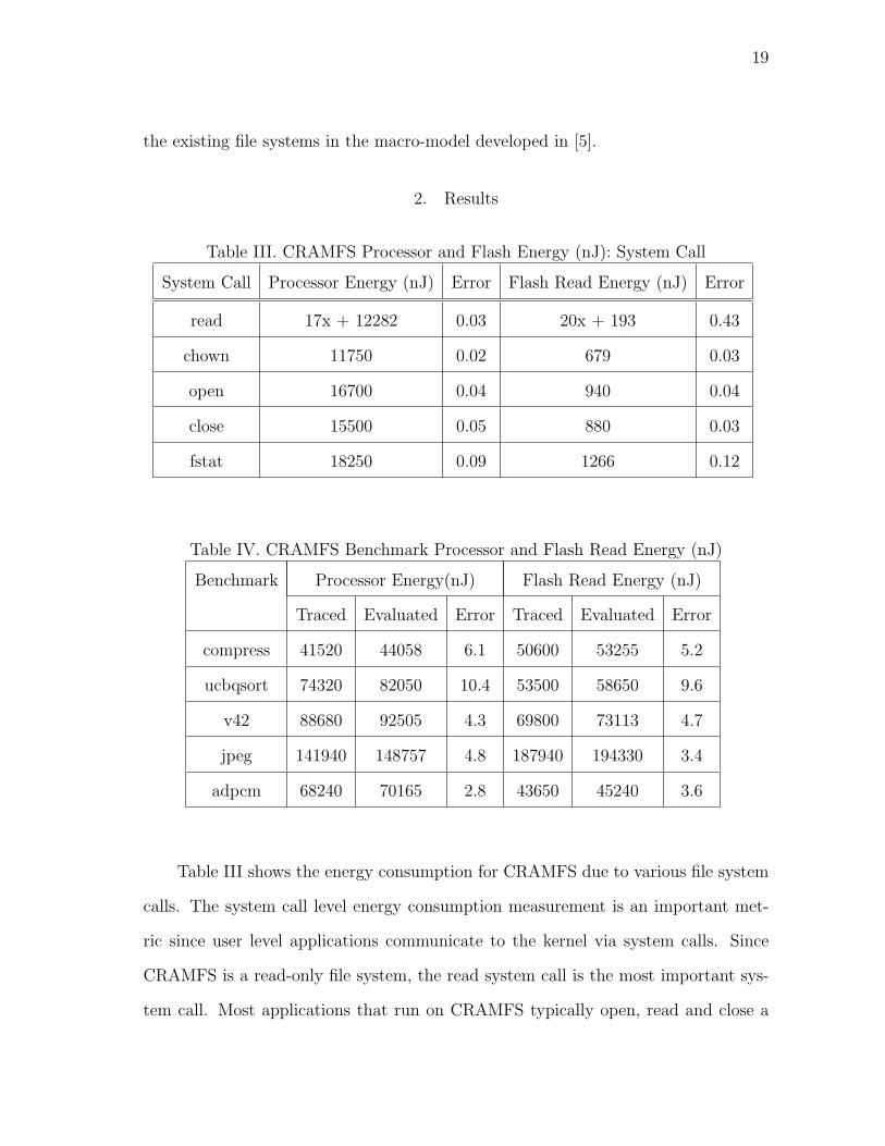
2. Results
Table III. CRAMFS Processor and Flash Energy (nJ): System Call
System Call Processor Energy (nJ) Error Flash Read Energy (nJ) Error
read 17x + 12282 0.03 20x + 193 0.43
chown 11750 0.02 679 0.03
open 16700 0.04 940 0.04
close 15500 0.05 880 0.03
fstat 18250 0.09 1266 0.12
Table IV. CRAMFS Benchmark Processor and Flash Read Energy (nJ)
Benchmark Processor Energy(nJ) Flash Read Energy (nJ)
Traced Evaluated Error Traced Evaluated Error
compress 41520 44058 6.1 50600 53255 5.2
ucbqsort 74320 82050 10.4 53500 58650 9.6
v42 88680 92505 4.3 69800 73113 4.7
jpeg 141940 148757 4.8 187940 194330 3.4
adpcm 68240 70165 2.8 43650 45240 3.6
Table III shows the energy consumption for CRAMFS due to various file system
calls. The system call level energy consumption measurement is an important met-
ric since user level applications communicate to the kernel via system calls. Since
CRAMFS is a read-only file system, the read system call is the most important sys-
tem call. Most applications that run on CRAMFS typically open, read and close a

20
file. The system calls chown, open, close and fstat have constant values since they
don’t depend on the file size. Although chown changes the ownership of a given file,
all changes are made in RAM and not written to flash. Upon system reboot, changes
made by the chown system call are lost.
Based on the above system call level equations, we have developed a tool for
CRAMFS to profile energy consumption due to higher level file system operations.
This tool first searches for file system related system calls used in a user program by
using the ”strace” unix command. Next, based on the results in Table III, the tool
calculates the total processor and flash energy consumption due to file system related
operations.
We evaluated the accuracy of the CRAMFS macro-model using selected bench-
marks from the PowerStone benchmark suite. The benchmarks were modified to ac-
commodate file reads. As Table IV shows, all benchmark tests were accurate within
10 percent margin of error. The percentage error shows the accuracy of the CRAMFS
macro-model. Such a macro-model can be very useful to a system designer to estimate
the energy consumption due to CRAMFS without using an actual power setup.
3. Analysis
In this section, we compare and contrast the file read performance of CRAMFS with
JFFS2 and EXT3. CRAMFS and EXT3 are both block based file systems while
JFFS2 directly reads and writes to flash. CRAMFS and JFFS2 both store compressed
data. Files are read by decompressing the data in the file on the fly. To study the
effects of compression, we analyze CRAMFS and JFFS2 both with files with worst
case compression (randomly generated data) and files with best case compression
(uniform data).
21
Reading File-CPU Energy Consumption
10000
100000
1000000
10000000
100 1000 10000 100000
File Size (Bytes)
Pro
ce
ss
or
En
erg
y C
on
su
mp
tio
n (
nJ
)
CRAMFS (worst case)
CRAMFS (with compression)
JFFS2 (worst case)
JFFS2 (with compression)
EXT3
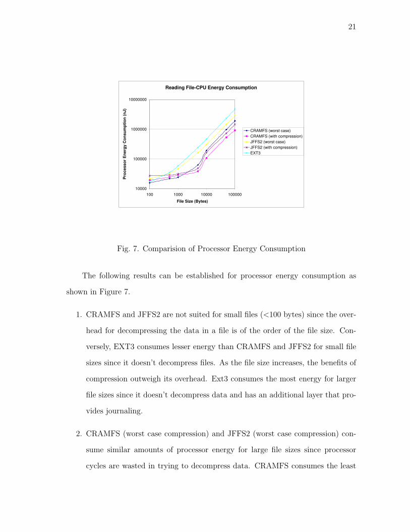
Fig. 7. Comparision of Processor Energy Consumption
The following results can be established for processor energy consumption as
shown in Figure 7.
1. CRAMFS and JFFS2 are not suited for small files (<100 bytes) since the over-
head for decompressing the data in a file is of the order of the file size. Con-
versely, EXT3 consumes lesser energy than CRAMFS and JFFS2 for small file
sizes since it doesn’t decompress files. As the file size increases, the benefits of
compression outweigh its overhead. Ext3 consumes the most energy for larger
file sizes since it doesn’t decompress data and has an additional layer that pro-
vides journaling.
2. CRAMFS (worst case compression) and JFFS2 (worst case compression) con-
sume similar amounts of processor energy for large file sizes since processor
cycles are wasted in trying to decompress data. CRAMFS consumes the least
22
amount of processor energy since it is designed as a simple, compressed, and
read-only file system. As a result, the data structures required to manage
CAMFS are simpler compared to JFFS2 and EXT3.
File Read- Flash Read Energy Consumption
1000
10000
100000
1000000
10000000
100 1000 10000 100000 1000000
File Size (Bytes)
Fla
sh
Re
ad
En
erg
y C
on
su
mp
tio
n (
nJ
)
cramfs worst
cramfs with
JFFS2 worst
JFFS2 with
EXT3
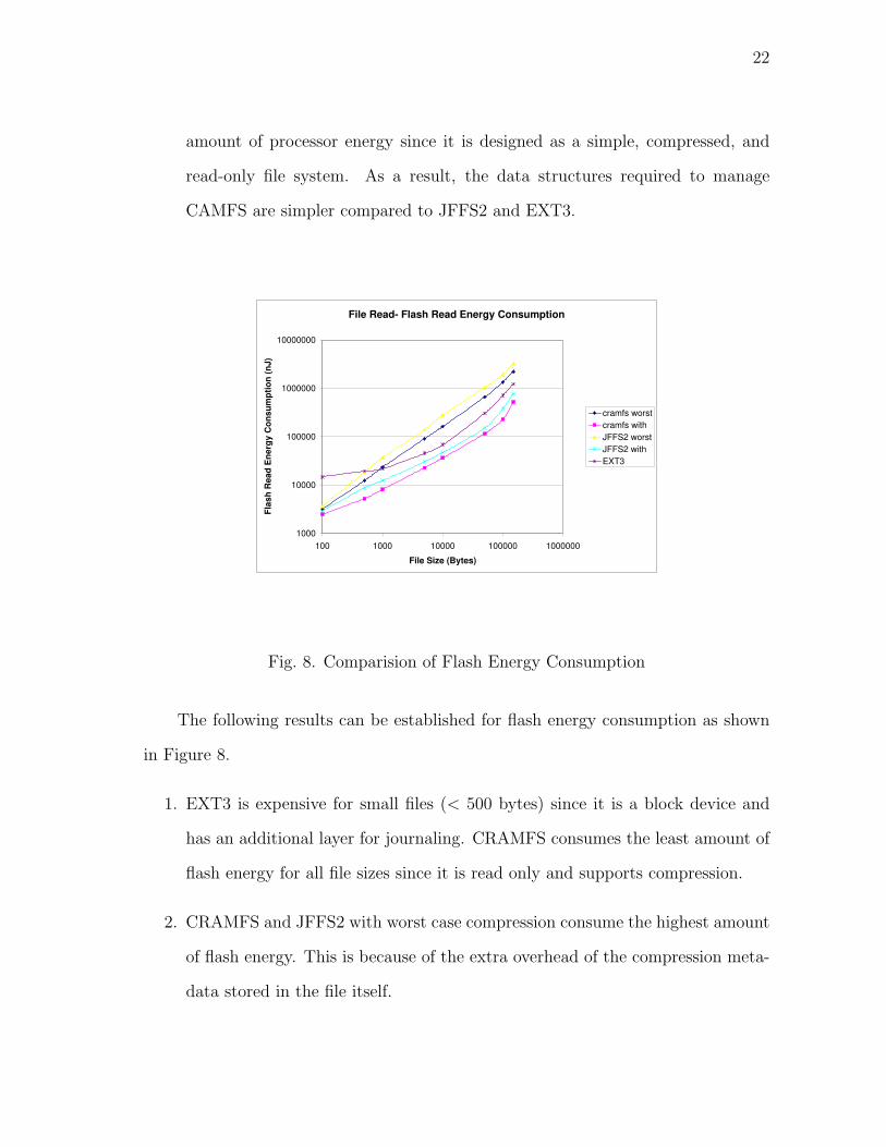
Fig. 8. Comparision of Flash Energy Consumption
The following results can be established for flash energy consumption as shown
in Figure 8.
1. EXT3 is expensive for small files (< 500 bytes) since it is a block device and
has an additional layer for journaling. CRAMFS consumes the least amount of
flash energy for all file sizes since it is read only and supports compression.
2. CRAMFS and JFFS2 with worst case compression consume the highest amount
of flash energy. This is because of the extra overhead of the compression meta-
data stored in the file itself.
23
CHAPTER IV
IMPROVING ENERGY EFFICIENCY OF JFFS2
A. Introduction
JFFS2 (Journaling Flash File System) [3] is a read/write and log based flash file sys-
tem that supports compression and wear-leveling. The JFFS file system was originally
designed by Axis Communications in Sweden. JFFS2 improved JFFS by improving
garbage collection, and adding support for compression and hard links. JFFS2 has
been very stable for NOR flash and is currently undergoing testing for NAND flash.
In this thesis, we focus on improving the write energy efficiency of JFFS2 for NOR
flash.
B. Operations in JFFS2
Timeline
Version: 1
Offset: 0
Len: 100
Data: AAA…
Version: 2
Offset: 50
Len: 60
Data: BBB…
Version: 3
Offset: 110
Len: 100
Data: CCC…
Flash Medium
User ActionWrite 100 bytes of ‘A’
at offset 0 on flash
Write 60 bytes of ‘B’at offset 60 on flash
Write 100 bytes of ‘C’at offset 110 on flash
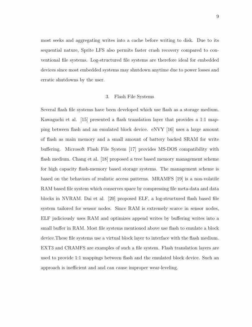
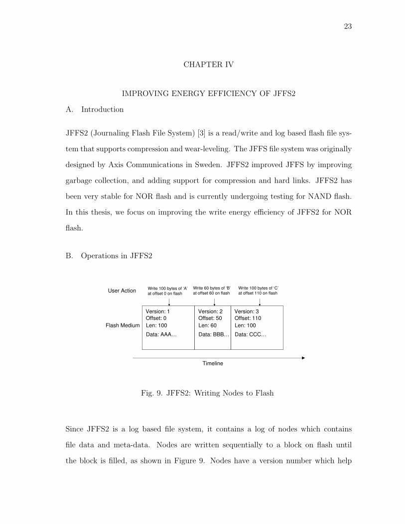
Fig. 9. JFFS2: Writing Nodes to Flash
Since JFFS2 is a log based file system, it contains a log of nodes which contains
file data and meta-data. Nodes are written sequentially to a block on flash until
the block is filled, as shown in Figure 9. Nodes have a version number which help
24
Timeline
Node PlaybackNode Version: 1
100 bytes at offset 0
Data Range Map
Node Version: 2
60 bytes at offset 50
Node Version: 3
100 bytes at offset 110
Ver 1: 0-100 Ver 1: 0-50
Ver 2: 50-110
Ver 1: 0-50
Ver 2: 50-110
Ver 3: 110-210
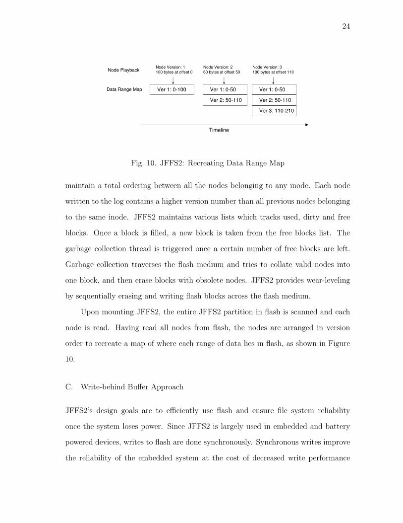
Fig. 10. JFFS2: Recreating Data Range Map
maintain a total ordering between all the nodes belonging to any inode. Each node
written to the log contains a higher version number than all previous nodes belonging
to the same inode. JFFS2 maintains various lists which tracks used, dirty and free
blocks. Once a block is filled, a new block is taken from the free blocks list. The
garbage collection thread is triggered once a certain number of free blocks are left.
Garbage collection traverses the flash medium and tries to collate valid nodes into
one block, and then erase blocks with obsolete nodes. JFFS2 provides wear-leveling
by sequentially erasing and writing flash blocks across the flash medium.
Upon mounting JFFS2, the entire JFFS2 partition in flash is scanned and each
node is read. Having read all nodes from flash, the nodes are arranged in version
order to recreate a map of where each range of data lies in flash, as shown in Figure
10.
C. Write-behind Buffer Approach
JFFS2’s design goals are to efficiently use flash and ensure file system reliability
once the system loses power. Since JFFS2 is largely used in embedded and battery
powered devices, writes to flash are done synchronously. Synchronous writes improve
the reliability of the embedded system at the cost of decreased write performance
25
and lower energy efficiency. As mentioned before, blocks in NAND flash are divided
into pages. Pages can only be written about 3-10 times before an erase of the block
is required. Thus, JFFS2 employs a small buffer for NAND flash which stores writes
to a page and is flushed upon being filled. NOR flash doesn’t have such a limit for
writing to a block. To improve the write performance of JFFS2 for NOR flash, we
have implemented a write-behind buffer of variable sizes. MRAM [8] is seen as a
promising emerging persistent RAM technology. Such a write-behind buffer could
be stored in MRAM to maintain system reliability. We assume that MRAM should
become widely available and economical in the near future [6].
D. Design of Write-behind Buffer
1. Data Structures
The write-behind buffer data structure consists of an array of bytes to store the buffer,
a lock to prevent concurrent accesses to the buffer, the current and previous buffer
offset, buffer size, current eraseblock, and the current eraseblock’s offset in flash.
NOR Flash
128KB block
128KB block
CurrentErase Block
Cleanmarker nodeCurrent Erase Block Offset
Clean
Dirty
Empty
.
.
.
Write-behind Buffer
4KB, 8KB, 16KB etc
FileFlush Buffer
Write data to Buffer
Write data directly to Flash
Dirty
Empty
.
.
.
Current Erase Block Offset
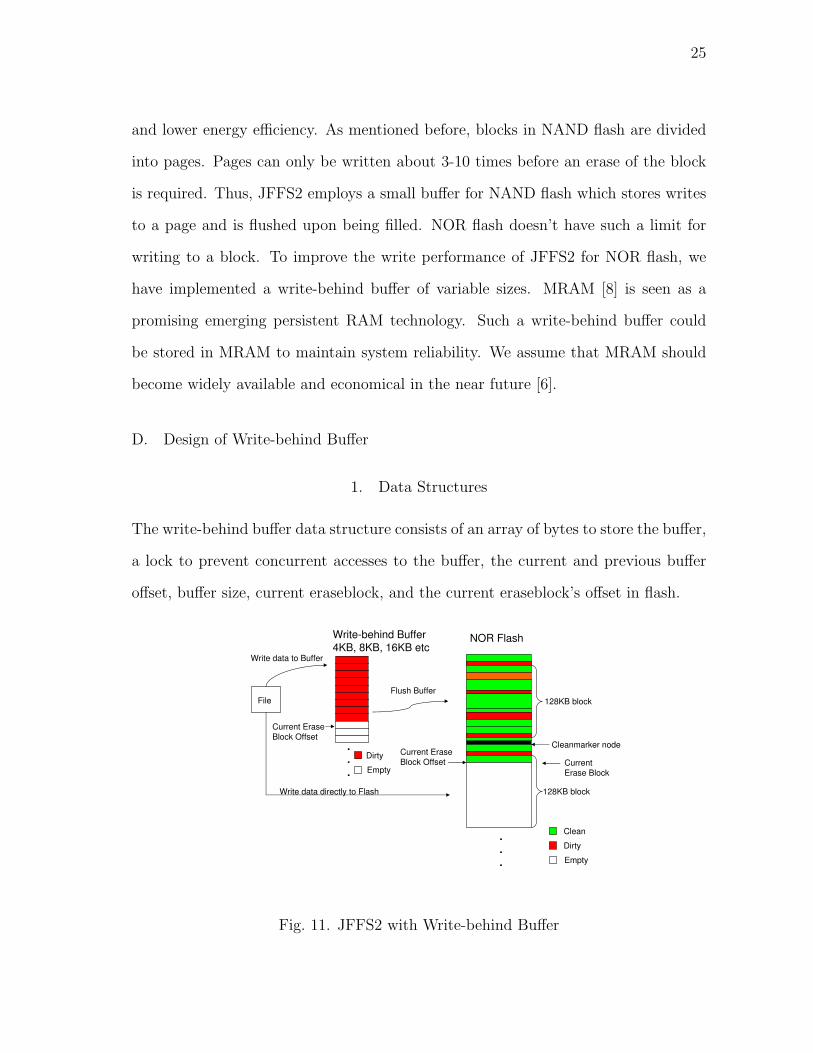
Fig. 11. JFFS2 with Write-behind Buffer
26
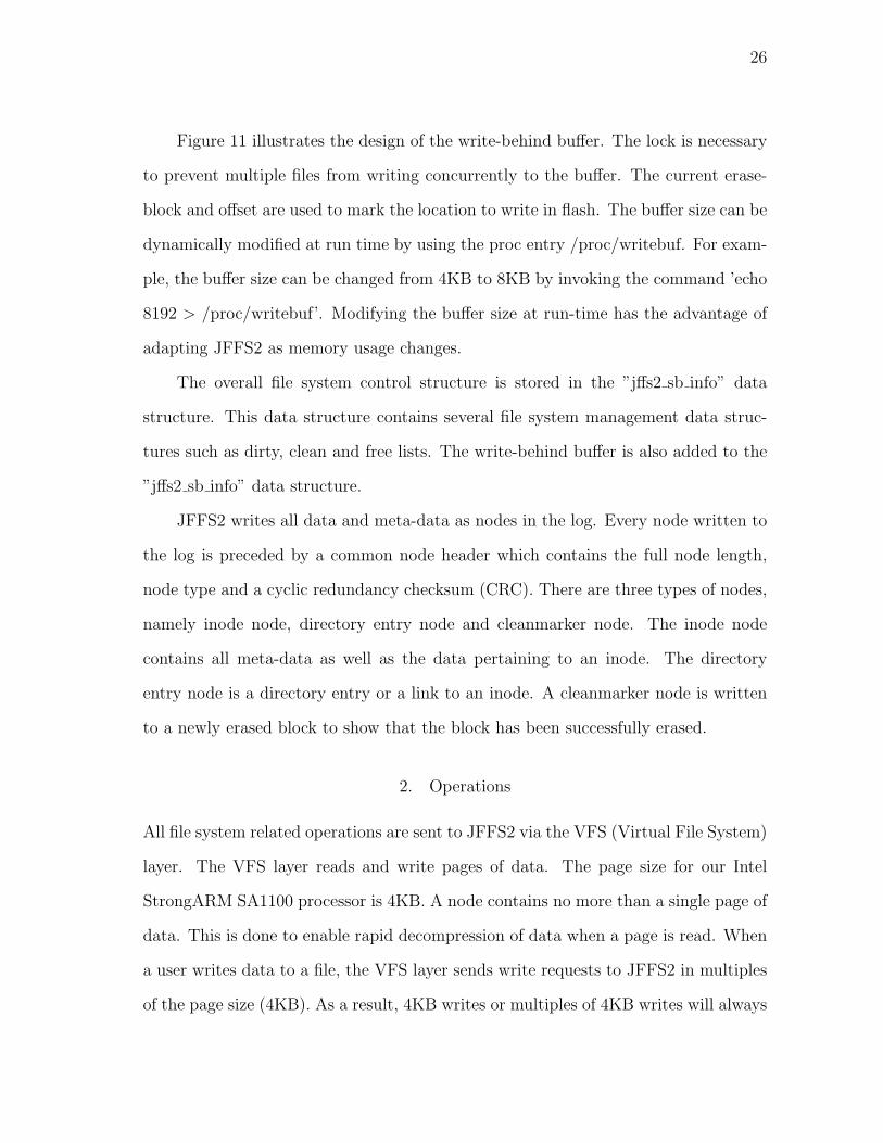
Figure 11 illustrates the design of the write-behind buffer. The lock is necessary
to prevent multiple files from writing concurrently to the buffer. The current erase-
block and offset are used to mark the location to write in flash. The buffer size can be
dynamically modified at run time by using the proc entry /proc/writebuf. For exam-
ple, the buffer size can be changed from 4KB to 8KB by invoking the command ’echo
8192 > /proc/writebuf’. Modifying the buffer size at run-time has the advantage of
adapting JFFS2 as memory usage changes.
The overall file system control structure is stored in the ”jffs2 sb info” data
structure. This data structure contains several file system management data struc-
tures such as dirty, clean and free lists. The write-behind buffer is also added to the
”jffs2 sb info” data structure.
JFFS2 writes all data and meta-data as nodes in the log. Every node written to
the log is preceded by a common node header which contains the full node length,
node type and a cyclic redundancy checksum (CRC). There are three types of nodes,
namely inode node, directory entry node and cleanmarker node. The inode node
contains all meta-data as well as the data pertaining to an inode. The directory
entry node is a directory entry or a link to an inode. A cleanmarker node is written
to a newly erased block to show that the block has been successfully erased.
2. Operations
All file system related operations are sent to JFFS2 via the VFS (Virtual File System)
layer. The VFS layer reads and write pages of data. The page size for our Intel
StrongARM SA1100 processor is 4KB. A node contains no more than a single page of
data. This is done to enable rapid decompression of data when a page is read. When
a user writes data to a file, the VFS layer sends write requests to JFFS2 in multiples
of the page size (4KB). As a result, 4KB writes or multiples of 4KB writes will always
27
write full nodes to the flash, preceded by a common node header. However, writes
smaller than 4KB will be less efficient due to the overhead of compression and the
common node header.
The following steps are taken to write data to a file in JFFS2 with a write-behind
buffer:
1. The data to be written to a file is sent as pages to JFFS2 via the VFS layer.
2. JFFS2 creates a node and common node header for the page of data sent.
3. The buffer tries to add the node and its preceding header to the byte array only
if it has available space. Flash is also checked for available space.
4. If the buffer doesn’t have sufficient space to add this node and its preceding
header, the buffer flushes its data to flash. Thereafter, the node and its header
are added to the buffer. If flash doesn’t have any free space, then garbage
collection is triggered to create space to write in flash.
5. The buffer tries to concatenate the previous node in the buffer with the current
node if they belong to the same file and their offsets are next to each other.
Compacting nodes help conserve flash space since fewer common header nodes
are written to flash. In addition, better compression ratios are achieved since
bigger nodes are compressed. Two nodes are compacted into one node only if
the size of the combined node is less than or equal to the page size (4KB). If
two nodes are compacted into one node, their corresponding file’s data range
map is updated to notify the location changes.
6. Steps 1-5 are repeated until all pages for the file write are written to the file.
While reading data from a file, the buffer is first checked to see if any of the data
nodes reside in the buffer. Nodes are read from flash if they don’t reside in the buffer.
28
3. Flushing the Buffer to Flash
The write-behind buffer is flushed from main memory to flash during any of the
following scenarios:
1. Buffer is full: The full buffer is written to flash to create space for future writes
to the buffer.
2. JFFS2 is mounted: If JFFS2 is mounted after a power loss, the buffer is flushed
to flash if it contains any data, thereby maintaining the reliability of JFFS2.
During a system shutdown due to power loss, the buffer doesn’t lose its data
since its designed to use MRAM.
3. JFFS2 is unmounted: When JFFS2 unmounts itself, it tries to leave JFFS2 in
a consistent state. As a result, all data from the buffer is written to flash.
4. ”fsync” command is invoked: fsync is a command which forces a file to syn-
chronize its data and metadata to flash.
5. ”kupdated” is invoked: kupdated is a kernel daemon which is triggered period-
ically to synchronize the file system.
All the nodes in the buffer are written to the current eraseblock in flash. The buffer
resets its current offset to the beginning of the buffer.
E. Experiment Results
1. Introduction
Since our experimental setup doesn’t have MRAM, the buffer is stored in DRAM for
experimental purposes. Our processor energy consumption results provide an upper
29
bound since MRAM consumes lesser energy than DRAM [6]. The most common
write file access patterns are small writes and large sequential writes. JFFS2 without
the write-behind buffer performs well for large sequential writes since full nodes are
written to flash. However, JFFS2 doesn’t perform well for small writes since it writes
synchronously to flash. To examine the effects of using a write-behind buffer for
JFFS2, we have ran our experiments on varying buffer sizes, such as 4 KB, 8 KB and
16KB. The experiments were ran 20 times for the different configurations and the
average results are shown.
2. Results and Analysis
a. Sequential Write Performance
Small sequential writes to the same file is a common file access pattern. Logs are
typically updated with small data periodically. In this experiment, we examine the
effect of the buffer size and append size on the processor and flash energy consumption.
A 64KB file is written sequentially at fixed intervals of time. The different append
sizes are 32, 64 and 128 bytes.
30
JFFS2 Sequential Write Performance
2000000
52000000
102000000
152000000
202000000
252000000
32 64 128 32 64 128 32 64 128 32 64 128
Without
Buffer
Buffer Size
4KB
Buffer Size
8KB
Buffer Size
16KB
Buffer Size KB
To
tal
En
erg
y (
nJ
)
Flash Write Energy (nJ)
Proc Write Energy (nJ)
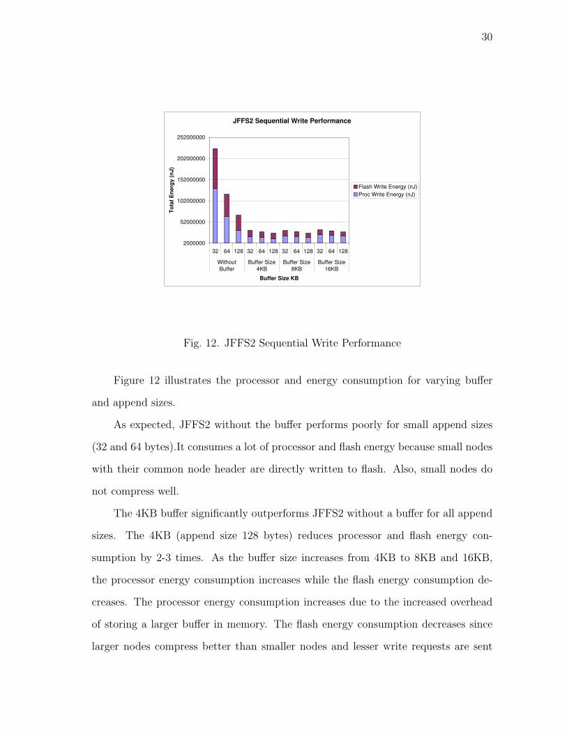
Fig. 12. JFFS2 Sequential Write Performance
Figure 12 illustrates the processor and energy consumption for varying buffer
and append sizes.
As expected, JFFS2 without the buffer performs poorly for small append sizes
(32 and 64 bytes).It consumes a lot of processor and flash energy because small nodes
with their common node header are directly written to flash. Also, small nodes do
not compress well.
The 4KB buffer significantly outperforms JFFS2 without a buffer for all append
sizes. The 4KB (append size 128 bytes) reduces processor and flash energy con-
sumption by 2-3 times. As the buffer size increases from 4KB to 8KB and 16KB,
the processor energy consumption increases while the flash energy consumption de-
creases. The processor energy consumption increases due to the increased overhead
of storing a larger buffer in memory. The flash energy consumption decreases since
larger nodes compress better than smaller nodes and lesser write requests are sent
31
to flash. Also, the different append sizes do not affect the energy consumption of a
given buffer size much. For instance, for a 16KB buffer, all three append sizes con-
sume similar amounts of processor and flash energy since the buffer flushes its data
once it full. Thus, the number of write requests are about the same.
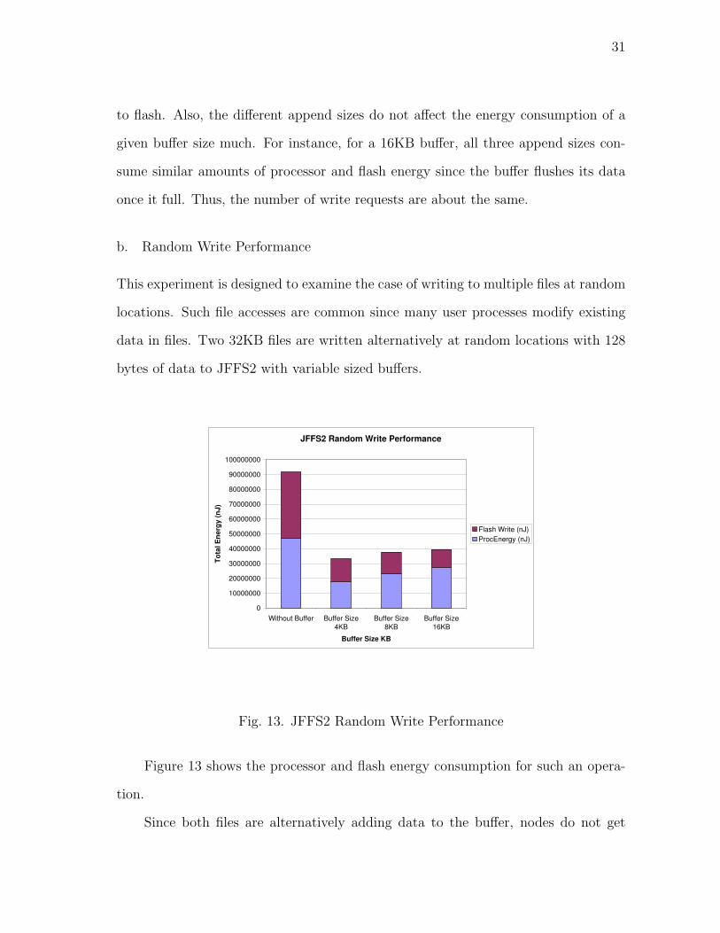
b. Random Write Performance
This experiment is designed to examine the case of writing to multiple files at random
locations. Such file accesses are common since many user processes modify existing
data in files. Two 32KB files are written alternatively at random locations with 128
bytes of data to JFFS2 with variable sized buffers.
JFFS2 Random Write Performance
0
10000000
20000000
30000000
40000000
50000000
60000000
70000000
80000000
90000000
100000000
Without Buffer Buffer Size
4KB
Buffer Size
8KB
Buffer Size
16KB
Buffer Size KB
To
tal
En
erg
y (
nJ
)
Flash Write (nJ)
ProcEnergy (nJ)
Fig. 13. JFFS2 Random Write Performance
Figure 13 shows the processor and flash energy consumption for such an opera-
tion.
Since both files are alternatively adding data to the buffer, nodes do not get

32
compacted since neighboring nodes in the buffer do not belong to the same file. The
buffer only compacts nodes belonging to the same file with offsets next to each other.
As a result, more data is written to flash, and thus the flash energy consumption is
higher for all buffers than for buffers with sequential writes. The 4KB buffer again
outperforms all other buffer sizes. The 4KB buffers’s total energy consumption is
33.39 milli-joules compared to 91.9 milli-joules for JFFS2 without a buffer. This ex-
periment shows that a small buffer does significantly reduce total energy consumption
for small random writes to a file.

33
CHAPTER V
CONCLUSION
In the first part of the thesis, a macro-model describing the processor and flash energy
consumption of the CRAMFS file system is developed. The file read operation of
CRAMFS is compared with JFFS2 and EXT3 to study the advantages of each. The
CRAMFS macro-model can be used by a system designer to estimate the power
consumption of CRAMFS without using an actual power setup.
The second part of this thesis examines the effects of using MRAM as a write-
behind buffer to improve the energy efficiency of JFFS2. Experimental results show
that a 4KB write-behind buffer significantly reduces energy consumption by up to 2-3
times for small consecutive writes and random writes. We assume that MRAM should
become widely available and economical in the near future [6]. A write-behind buffer
using MRAM could improve energy efficiency and maintain file system reliability.
34
CHAPTER VI
FUTURE WORK
A. Macro-model for JFFS2 (NAND Flash) and YAFFS
YAFFS is a NAND flash based file system. JFFS2 recently offered support for NAND
flash. As NAND flash is cheaper and offers more storage space than NOR flash, many
large non-volatile embedded storage applications such as file storage and portable
media player applications are using NAND flash as a persistent storage medium. A
macro-model for JFFS2 (NAND flash) and YAFFS could be developed specifically
for NAND flash.
B. Energy Efficient Garbage Collection for JFFS2
JFFS2 performs garbage collection to reclaim dirty space from the flash medium. The
garbage collection thread tries to erase blocks by moving valid nodes to the tail of
the log. This operation is designed for speed and not energy efficiency. A garbage
collection algorithm needs to be developed which is fast and energy efficient.
35
REFERENCES
[1] J. Zedlewski, S. Sobti, N. Garg, F. Zheng, A. Krishnamurthy, and R. Wang,
“Modeling hard-disk power consumption,” in Second Conference on File and
Storage Technologies, San Francisco, CA, March 2003, pp. 217–230.
[2] J. T. Moore, M. Hicks, and S. Nettles, “General-purpose persistence using flash
memory,” Technical Report MS-CIS-97-3, Department of Computer and Infor-
mation Science, University of Pennsylvania, Philadelphia, 1997.
[3] D. Woodhouse, “JFFS,” http://sources.redhat.com/jffs2/jffs2.pdf, 2001.
[4] C. Manning, “YAFFS,” http://www.aleph1.co.uk/yaffs/yaffs.html, September
2004.
[5] S. Choudhury and R. N. Mahapatra, “Energy characterization of filesystems for
diskless embedded systems,” in Design Automation Conference, San Diego, CA,
2004, pp. 566–569.
[6] Freescale, “MRAM fact sheet,” http://www.freescale.com/files/technology
manufacturing/doc/MRAM FACT SHEET.pdf, September 2004.
[7] L. Torvalds, “CRAMFS,” http://lxr.linux.no/source/fs/cramfs/README, Au-
gust 2002.
[8] H. Boeve, C. Bruynseraede, J. Das, K. Dessein, G. Borghs, J. De Boeck, R. C.
Sousa, L. V. Melo, and P. P. Freitas, “Technology assessment for the implemen-
tation of magnetoresistive elements with semiconductor components in magnetic
random access memory (MRAM) architectures,” IEEE Transactions on Mag-
netics, vol. 35, no. 2, pp. 2820–2825, September 1999.
36
[9] IBM, “IBM magentic RAM (MRAM),” http://www.research.ibm.com/resources/
news/20001207 mramimages.shtml, September 2004.
[10] Wikipedia, “Flash memory,” http://en.wikipedia.org/wiki/Flashmemory, Sep-
tember 2004.
[11] T. K. Tan, A. Raghunathan, G. Lakshminarayana, and N. K. Jha, “High-level
software energy macro-modeling,” in Design Automation Conference, Las Vegas,
NV, 2001, pp. 605–610.
[12] N. Jha, T. K. Tan, and A. Raghunathan, “Embedded operating system energy
analysis and macro-modeling,” in International Conference on Computer Design,
Freiburg, Germany, 2002, pp. 515–522.
[13] S. Tweedie, “Journaling the Linux ext2fs filesystem,” in LinuxExpo, Durham,
NC, 1998, pp. 25–29.
[14] M. Rosenblum and J. K. Ousterhout, “The design and implementation of a log-
structured file system,” ACM Transactions on Computer Systems, vol. 10, no.
1, pp. 26–52, 1992.
[15] A. Kawaguchi, S. Nishioka, and H. Motoda, “A flash-memory based file system,”
in USENIX Winter, New Orleans, LA, 1995, pp. 155–164.
[16] M. Wu and W. Zwaenepoel, “eNVy: A nonvolatile main memory storage sys-
tem,” in Workshop on Workstation Operating Systems, Napa, CA, 1993, pp.
116–118.
[17] M. Levy, “Interfacing Microsoft’s Flash File System,” Intel Corporation, Port-
land, Oregon, 1993.
37
[18] L. Chang and T. Kuo, “An efficient management scheme for large-scale flash-
memory storage systems,” in ACM SIG Symposium on Applied Computing,
Nicosia, Cyprus, March 2004, pp. 862–868.
[19] E. L. Miller N. K. Edel, D. Tuteja and S. A. Brandt, “Mramfs: A compressing file
system for non-volatile ram,” in International Symposium on Modeling, Analy-
sis, and Simulation of Computer and Telecommunication Systems, Volendam,
Netherlands, 2004, pp. 596–603.
[20] M. Neufeld H. Dai and R. Han, “Elf: An efficient log-structured flash file system
for micro sensor nodes,” in 2nd ACM Conference on Embedded Networked
Sensor Systems, Baltimore, Maryland, November 2004, pp. 176–187.
[21] J. Pouwelse, “The LART pages,” http://www.lart.tudelft.nl/, May, 2003.
[22] Intel, “Intel StrongARM processor,” http://www.intel.com/design/pca/applications
processors/1110 brf.htm, June 2004.
[23] Intel, “Intel fast boot block flash memory,” http://www.intel.com/design/flash/
support/DevChar/28f800f3.htm, May 2003.
[24] Compaq, “iPAQ homepage,” http://www5.compaq.com/products/handhelds/
pocketpc, August 2004.

38
APPENDIX A
CREATING A CRAMFS FLASH BASED IMAGE
1. First create a directory of files which are wanted in the requiredfilesystem image
$ mkdir sample$ cp -r /bin /tmp/sample
/tmp/sample contains a copy of the folder in /bin
2. Create the CRAMFS filesystem image out of the folder in /tmp/sample$ mkcramfs /tmp/sample cramfs.img
cramfs.image is the name of the output file that has the CRAMFS image
3. Erase the flash partition$ eraseall /dev/mtd2
This command erases the 3MB partition on flash that is used for thefilesystem
4. Download the CRAMFS image (cramfs.img) to the LART boardusing z-modem serial transfer
5. Copy the filesystem image onto the flash partition$ cat cramfs.img > /dev/mtd2
6. Load the CRAMFS module into the kernel$ modprobe -a cramfs
7. Mount the CRAMFS filesystem$ mount -t cramfs /dev/mtdblock2 /mnt

39
VITA
Nitesh Goyal received his B.S. degree in computer science with Honors from The Uni-
versity of Texas at Austin in 2002. He has interned at various prominent technology
companies such as Microsoft, JDEdwards and National Instruments.
Permanent Address
67 Gashi Avenue,
Mufulira
ZAMBIA
The typist for this thesis was Nitesh Goyal.