Embed Size (px)
Citation preview
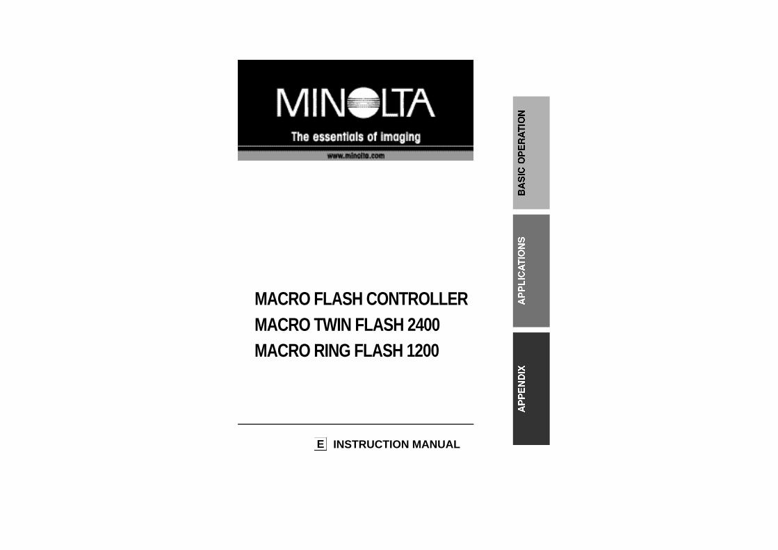
MACRO FLASH CONTROLLERMACRO TWIN FLASH 2400MACRO RING FLASH 1200
E INSTRUCTION MANUAL
32
Names of Parts......................................................................................10
BASIC OPERATIONInstalling Batteries.................................................................................15
Checking Batteries ......................................................................16Attaching and Removing the Controller.................................................17Attaching the Twin Flash.......................................................................18Attaching the Ring Flash.......................................................................23Turning the Flash On and Off................................................................25Film .....................................................................................................25Basic Flash Mode..................................................................................26
Selecting Apertures - TTL Flash -................................................30P Mode.........................................................................................33
DETAILED OPERATIONSManual Flash.........................................................................................35
Manual Flash (M) with Twin Flash ..............................................35Manual Flash (M) with Ring Flash...............................................37Manual Flash - Selecting Apertures and Power Levels..............38
Test Flash .............................................................................................44Modeling Flash (Twin Flash Only).........................................................45Wide Angle Adapter (Twin Flash Only)..................................................46Diffuser (Twin Flash Only).....................................................................48Focus Lamps (Ring Flash Only)............................................................51Custom Functions..................................................................................52
APPENDIXExamples of Twin Flash Photography...................................................56Examples of Ring Flash Photography...................................................59Aperture Range Graphs - Twin Flash....................................................60Aperture Range Graphs - Ring Flash....................................................62Compatibility .........................................................................................64Care and Storage..................................................................................66Specifications.........................................................................................68
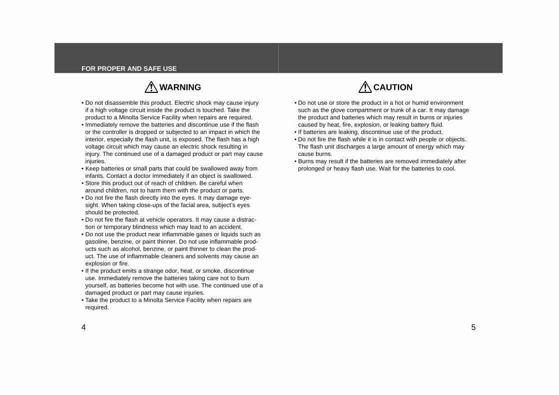
CONTENTS FOR PROPER AND SAFE USEPlease read and understand all warnings and cautions before usingthis product.
WARNING• Do not put your finger or metalic objects into the cord sockets on
the controller. Be careful not to let moisture such as rain enter thesocket(s). It may cause an electric shock. Attach the protectivesocket caps when not in use.
• When unplugging the cord, do not pull on the cord. Hold the plugwhen removing.
• Do not damage, twist, modify, or heat the cord. A damaged cordmay cause damage or injury through fire or electric shock.
Using batteries improperly can cause them to leak harmful solu-tions, overheat, or explode which may damage property or causepersonal injury. Do not ignore the following warnings.• Only use the batteries specified in this instruction manual.• Do not install the batteries with the polarity (+/–) reversed.• Do not use batteries which show wear or damage.• Do not expose batteries to fire, high temperatures, water, or mois-
ture.• Do not attempt to short or disassemble batteries.• Do not store batteries near or in metallic products.• Do not mix batteries of different types, brands, or ages; recharge-
able batteries should be charged together, so that the batterypower is equal. Do not attempt to recharge akaline or lithium bat-teries.
• Do not use leaking batteries. If fluid from the batteries enters youreye, immediately rinse the eye with plenty of fresh water and con-tact a doctor. If fluid from the batteries makes contact with yourskin or clothing, wash the area thoroughly with water.
• Tape over lithium battery contacts to avoid short-circuiting duringdisposal; always follow local regulations for battery disposal.
54
WARNING
• Do not disassemble this product. Electric shock may cause injuryif a high voltage circuit inside the product is touched. Take theproduct to a Minolta Service Facility when repairs are required.
• Immediately remove the batteries and discontinue use if the flashor the controller is dropped or subjected to an impact in which theinterior, especially the flash unit, is exposed. The flash has a highvoltage circuit which may cause an electric shock resulting ininjury. The continued use of a damaged product or part may causeinjuries.
• Keep batteries or small parts that could be swallowed away frominfants. Contact a doctor immediately if an object is swallowed.
• Store this product out of reach of children. Be careful whenaround children, not to harm them with the product or parts.
• Do not fire the flash directly into the eyes. It may damage eye-sight. When taking close-ups of the facial area, subject’s eyesshould be protected.
• Do not fire the flash at vehicle operators. It may cause a distrac-tion or temporary blindness which may lead to an accident.
• Do not use the product near inflammable gases or liquids such asgasoline, benzine, or paint thinner. Do not use inflammable prod-ucts such as alcohol, benzine, or paint thinner to clean the prod-uct. The use of inflammable cleaners and solvents may cause anexplosion or fire.
• If the product emits a strange odor, heat, or smoke, discontinueuse. Immediately remove the batteries taking care not to burnyourself, as batteries become hot with use. The continued use of adamaged product or part may cause injuries.
• Take the product to a Minolta Service Facility when repairs arerequired.
CAUTION
• Do not use or store the product in a hot or humid environmentsuch as the glove compartment or trunk of a car. It may damagethe product and batteries which may result in burns or injuriescaused by heat, fire, explosion, or leaking battery fluid.
• If batteries are leaking, discontinue use of the product.• Do not fire the flash while it is in contact with people or objects.
The flash unit discharges a large amount of energy which maycause burns.
• Burns may result if the batteries are removed immediately afterprolonged or heavy flash use. Wait for the batteries to cool.
FOR PROPER AND SAFE USE
6 7
This device complies with Part 15 of the FCC Rules. Operation issubject to the following two conditions: (1) This device may not causeharmful interference, and (2) this device must accept any interferencereceived, including interference that may cause undesired operation.Changes or modifications not approved by the party responsible forcompliance could void the user's authority to operate the equipment.This equipment has been tested and found to comply with the limits fora Class B digital device, pursuant to Part 15 of the FCC Rules. Theselimits are designed to provide reasonable protection against harmfulinterference in a residential installation. This equipment generates, usesand can radiate radio frequency energy and, if not installed and used inaccordance with the instructions, may cause harmful interference toradio communications.However, there is no guarantee that interference will not occur in aparticular installation. If this equipment does cause harmful interferenceto radio or television reception, which can be determined by turning theequipment off and on, the user is encouraged to try to correct theinterference by one or more of the following measures:• Reorient or relocate the receiving antenna.• Increase the separation between the equipment and the receiver.• Connect the equipment to an outlet on a circuit different from that to
which the receiver is connected.• Consult the dealer or an experienced radio/TV technician for help.
This Class B digital apparatus complies with Canadian ICES-003.
Thank you for purchasing this Minolta product. Please read thismanual thoroughly before using the macro flash or ring flash. Wehope that you will continue to be satisfied by our products.
These products are designed and manufactured for use withMinolta Maxxum/Dynax series cameras and some Minolta digitalcameras. Performance when used with cameras from other man-ufacturers cannot be guaranteed. Minolta takes no responsibilityfor accidents or malfunctions due to use with such cameras.
The information in this manual is relevant for products introducedbefore February 2001. Contact the nearest authorized MinoltaService Facility to obtain information for products released afterthis date.
This mark certifies that these products meets therequirements of the EU (European Union) concerninginterference causing equipment regulations. CE stands forconformité Européenne (European conformity).
The AC Adapter for this Macro Flash Controller is available only inJapan. The use of an AC Adapter other than the specified unit canpermanently damage the flash and cause heat or fire.

Twin Flash (2 flashtubes)
98
MACRO FLASH OPTIONSThere are two types of lighting available; twin flash and ring flash.Choose one, depending on your subject.
A wide choice of lighting variations is possible when the Macro TwinFlash 2400 is used with the Macro Flash Controller. Suitable forphotographing flowers, insects, and small objects.
Ring Flash (4 flashtubes)
Use the optional Macro Ring Flash 1200 with the Macro FlashController. Used for photographing small subjects in fine detail andfor scientific applications.
• The Macro Ring Flash 1200 is identical to that provided in theMacro Flash 1200AF set. If you already have the Macro Flash1200AF set, it is only necessary to purchase the Macro FlashController.
• Each part may be purchased separately.• The Macro Twin Flash 2400 cannot be used with the AF Macro
Zoom 3X-1X f/1.7-2.8 lens.• Twin flash and the ring flash cannot be used together. When both
are connected, only the twin flash will fire.
Macro Twin Flash 2400(Includes two units)
Macro Flash Controller
Macro Ring Flash 1200
Macro Flash Controller
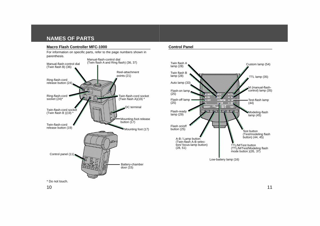
* Do not touch.
For information on specific parts, refer to the page numbers shown inparenthesis.
Control Panel
1110
NAMES OF PARTS
Manual-flash-control dial(Twin flash B) (36)
Ring-flash-cordsocket (24)*
Twin-flash-cordrelease button (19)
Battery-chamberdoor (15)
Flash-on lamp(25)
Flash-off lamp(25)
Flash-readylamp (29)
Low-battery lamp (16)
Twin-flash-cord socket(Twin flash A)(19) *
Flash on/offbutton (25)
Twin flash Alamp (28)
Twin flash Blamp (28)
Macro Flash Controller MFC-1000
Auto lamp (33)
A-B / Lamp button(Twin-flash A-B selec-tion/ focus-lamp button)(28, 51)
TTL/M/Test button(TTL/M/Test/Modeling flashmode button )(35, 37)
Test button(Test/modeling flashbutton) (44, 45)
TTL lamp (35)
Test-flash lamp(44)
Custom lamp (54)
Ring-flash-cordrelease button (24)
Twin-flash-cord socket (Twin flash B )(19) *
Reel-attachmentpoints (21)
DC terminal
Mounting-foot-releasebutton (17)
Mounting foot (17)
Control panel (11)
Modeling-flashlamp (45)
M (manual-flash-control) lamp (35)
Manual-flash-control dial(Twin flash A and Ring flash) (36, 37)
1312
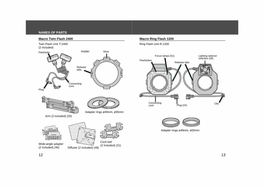
NAMES OF PARTS
Adapter rings ø49mm, ø55mm
Cord reel(2 included) (21)
Diffuser (2 included) (48)
Holder
Wide-angle adapter(2 included) (46)
Arm (2 included) (20)
Plug
Twin Flash Unit T-2400 (2 included)
Ring Flash Unit R-1200
Macro Twin Flash 2400 Macro Ring Flash 1200
Connectingcord
Flashtube Shoe
Releasetabs
Adapter rings ø49mm, ø55mm
Clip
Lighting-selectorswitches (28)
Focus lamps (51)
Release tabs Flashtubes
Connectingcord Plug (24)
14 15
BASIC OPERATION
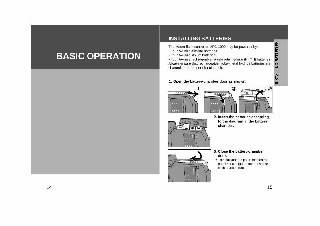
INSTALLING BATTERIESThe Macro flash controller MFC-1000 may be powered by:• Four AA-size alkaline batteries• Four AA-size lithium batteries• Four AA-size rechargeable nickel-metal hydride (Ni-MH) batteriesAlways ensure that rechargeable nickel-metal hydride batteries arecharged in the proper charging unit.
1. Open the battery-chamber door as shown.
3. Close the battery-chamberdoor.
• The indicator lamps on the controlpanel should light. If not, press theflash on/off button.
2. Insert the batteries accordingto the diagram in the batterychamber.
1716
INSTALLING BATTERIES
Checking BatteriesThe lamp on the control panel glows or blinks when the batter-ies are low.
When glowing; Power is low. The bat-teries will need to be replaced soon.
When blinking; Insert new batteries.Flash cannot be used.
• Check the orientation of the batteries if nothing appears when the con-troller’s flash on/off button is pressed.
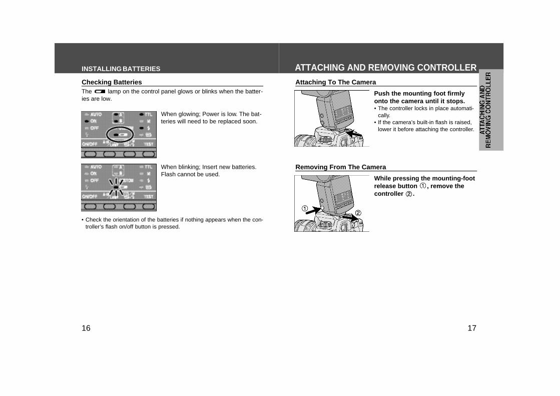
Removing From The Camera
While pressing the mounting-footrelease button , remove thecontroller .
Attaching To The Camera
Push the mounting foot firmlyonto the camera until it stops.• The controller locks in place automati-
cally.• If the camera’s built-in flash is raised,
lower it before attaching the controller.
ATTACHING AND REMOVING CONTROLLER
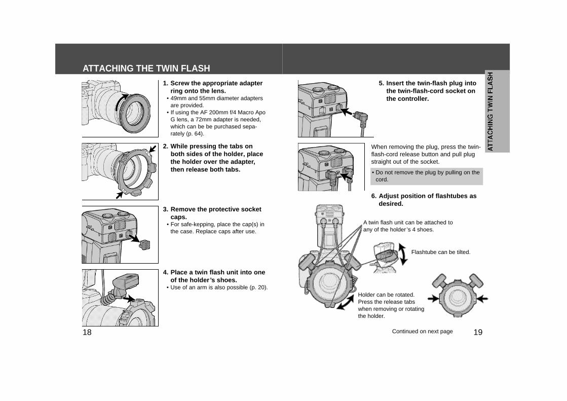
2. While pressing the tabs onboth sides of the holder, placethe holder over the adapter,then release both tabs.
4. Place a twin flash unit into oneof the holder’s shoes.
• Use of an arm is also possible (p. 20).
3. Remove the protective socketcaps.
• For safe-kepping, place the cap(s) inthe case. Replace caps after use.
5. Insert the twin-flash plug intothe twin-flash-cord socket onthe controller.
1918
ATTACHING THE TWIN FLASH1. Screw the appropriate adapter
ring onto the lens.• 49mm and 55mm diameter adapters
are provided.• If using the AF 200mm f/4 Macro Apo
G lens, a 72mm adapter is needed,which can be be purchased sepa-rately (p. 64).
When removing the plug, press the twin-flash-cord release button and pull plugstraight out of the socket.
A twin flash unit can be attached toany of the holder ’s 4 shoes.
Flashtube can be tilted.
Holder can be rotated.Press the release tabswhen removing or rotatingthe holder.
6. Adjust position of flashtubes asdesired.
• Do not remove the plug by pulling on thecord.
Continued on next page
2120
ATTACHING THE TWIN FLASH
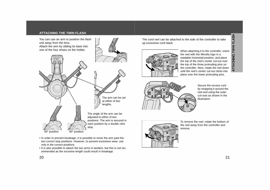
You can use an arm to position the flashunit away from the lens.Attach the arm by sliding its base intoone of the four shoes on the holder.
The arm can be setat either of twolengths.
The angle of the arm can beadjusted to either of twopositions. The arm is secured ineach position by a double clickstop.
To remove the reel, rotate the bottom ofthe reel away from the controller andremove.
• In order to prevent breakage, it is possible to move the arm past thetwo correct stop positions. However, to prevent excessive wear, useonly in the correct positions.
• It is also possible to attach the two arms in tandem, but this is not rec-ommended as the excesive length could result in breakage.
The cord reel can be attached to the side of the controller to takeup excessive cord slack.
When attaching it to the controller, orientthe reel with the Minolta logo in areadable horizontal position, and placethe top of the reel’s center cut-out overthe top of the three protruding pins onthe controller. Next, rotate the reel downuntil the reel’s center cut-out clicks intoplace over the lower protruding pins.
Secure the excess cordby wrapping it around thereel and using the outercut-outs as shown in theillustration.
60° position 90° position
2322
ATTACHING THE RING FLASH
2. While pressing the tabs onboth sides of the ring flash,place the ring flash over theadapter, then release bothtabs.
• Attach the ring flash directly to the AFMacro Zoom 3X-1X f/1.7-2.8 lens.
3. Remove the protective socketcap.
• For safe-keeping, place cap in bag.Replace cap after use.
1. Screw the appropriate adapterring onto the lens.
• 49mm and 55mm diameter adaptersare provided.
• If using the AF 200mm f/4 Macro ApoG lens, a 72mm adapter is needed,which can be be purchased sepa-rately (p. 64).
Strong shadows can be softened byusing the diffuser attached to theflashtube. Always use the diffuser withan arm (p. 48).
The angle of flash coveragewill increase if you attach thewide-angle adapter to theflashtube (p. 46).
• Do not allow the cord to get in front of the flashtube or lens.• Make sure the flashtube is pointing at the subject.• See page 56 for photographic examples.• If an arm is used when taking very close-ups with the AF Macro 50mm
f/2.8 lens, the subject may not receive sufficient lighting (p. 57).• The AF Macro Zoom 3X-1X f1.7-2.8 lens can not be used with the
twin flash.
ATTACHING THE TWIN FLASH
Continued on next page
2524
ON/OFF
TURNING THE FLASH ON AND OFF/ FILM
When the flash turns on, the flash-on lampwill glow.
With the flash on, pressing the flash on/offbutton will turn the flash off and flash-offlamp will glow.• The lamp will go out after a little more than
10 seconds.
Turn the flash on by pressing the flashon/off button.
• When the flash is attached and you operate your camera, power issupplied automatically to the flash, and the lamp will glow. (auto poweron). Power is switched off and lamps go out automatically to save bat-teries when the camera or flash is not used for four minutes (autopower off).
• Custom settings may be used to change the time of auto power off, orto disable auto power off (p. 52).
Do not use high-speed film (rating in excess of ISO 1000) with TTLdirect metering (TTLlamp will be on, see page 35). Use of such filmincreases the exposure error.• The low-speed film limit is the same as that for the films specified for
the camera. See the camera manual for details.
Film
ATTACHING THE RING FLASH
4. Insert the ring-flash plug intothe ring-flash-cord socket onthe controller.
• Press the release tabs when removingthe ring flash.
• Do not allow the cord to get in front of thelens or ring flashtubes. Use the cord clipto secure the cord.
• See page 59 for photographic examples.
When removing the plug, press the ring-flash-cord release button and pull plugstraight out of the socket.
• Do not remove the plug by pulling on thecord.

2726
1. Turn camera on and set to Amode or M mode.
2. Turn the flash on by pressingthe flash on/off button. Theflash-on lamp will glow.
4. When using M mode, select ashutter speed that is slowerthan the camera’s sync speed.
3. Focus your subject and checkthe magnification ratio.
• The location of the magnification ratioscale differs, depending on whichlens is used.
5. Select an aperture. Refer to thetables on pages 30 to 32.
BASIC FLASH MODESCamera’s exposure mode should be set to either A (aper-ture priority) mode*, or M (manual) mode**.Depth-of-field*** is quite shallow at close-up and macro ranges, sofocusing is very important. It is recommended that you use a macrolens and select an aperture as small as practical to maximize thedepth-of-field.In this section, the basic flash operation in A or M mode with TTLmetering (TTL lamp on) is described.
*A mode: In A mode, you select the aperture and the cameraautomatically sets the shutter speed required for proper exposure.**M mode: You can select both aperture or shutter speed. HSS (high-apeed sync) is not possible.***Depth-of-field: The range behind and in front of the subject thatappears sharp.
This part of the manual assumes that the user is using one ofthe following cameras and macro lens.
Camera: A camera having A mode (aperture priority) or M mode(manual).
Lens: AF 50mm f/2.8 Macro AF 50mm f/2.8 (D) Macro AF 50mm f3.5 Macro AF 100mm f/2.8 Macro AF 100mm f/2.8 (D) Macro AF 200mm f/4 Macro Apo GAF Macro Zoom 3X-1X f/1.7-2.8
If you use a camera other than one listed above, refer to P modeflash section (p. 33). If using a different lens, see pages 60 and 62.
Continued on next page
2928
6. Select the flash.In the case of the twin flash, eachpress of the A-B / lamp button causesthe selected flash units to go fromboth A and B, then only A, and finallyonly B.
The ring flash has four separateflashtubes. These can be turnedon or off independently by usingthe lighting-selector switches onthe back of the unit. When theswitch shows red, that flashtube ison. When black, that flashtube isoff.
As viewed from the rear(control panel side), the Aflash is the one connected tothe left side socket, the Bflash to the right side.
7. When the flash is charged,press the shutter-release but-ton to take the photo.
• The flash is charged when is lit onthe rear of the unit, and alsoappears in the camera viewfinder.
When the correct exposure wasobtained for the photo just taken:• The flash-ready lamp blinks on the
control panel for two seconds.• blinks in the camera viewfinder.
• The photo will be under-exposed if taken before charging is complete.• The use of a tripod or remote cord is recommended to reduce camera
shake.• Camera-to-subject distance of less than 0.5m, and a magnification
ratio of more than 0.15X (greater than 1:7), are recommended to getthe best results from the macro flash units.
• When neither a twin flash or ring flash is attached, turn the controlleroff. Otherwise proper exposure will not be obtained.
• The camera’s AF illuminator is blocked by the adapter ring or flashand cannot be used for focusing.
BASIC FLASH MODES
• If you turn off the ring flash while it is connected to the controller,press the flash on/off button on the controller. Proper exposure will notbe obtained if only the four lighting-selector switches on the ring flashare turned off.
A B
Right flashtube All flashtubes
3130
BASIC FLASH MODES
3.5 ~ 762.4 ~ 54
2 ~ 451.4 ~ 32
1.2 ~ 270.85 ~ 191.4 ~ 32
3.5 ~ 762.4 ~ 54
2.8 ~ 642 ~ 45
1.7 ~ 381.2 ~ 271.4 ~ 32
2.8 ~ 642 ~45
2.8 ~ 642 ~ 45
2 ~451.4 ~ 321.2 ~ 27
2.4 ~ 541.7 ~38
2.8 ~ 642 ~ 45
2 ~451.4 ~ 321 ~ 22
Upper set of numbers is for two twin flash units.Lower set is for one twin flash unit.Ring flash is common for 1 ~ 4 tubes.
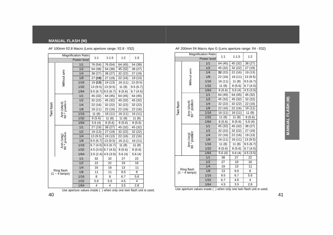
AF 100mm f/2.8 Macro (Lens aperture range: f/2.8 - f/32)
2.8 ~ 642 ~ 45
2.8 ~ 642 ~ 45
2 ~ 451.4 ~ 321.7 ~ 38
2 ~ 451.4 ~ 32
2.8 ~ 642 ~ 45
2 ~ 451.4 ~ 321.2 ~ 27
1.7 ~ 381.2 ~ 27
2 ~ 451.4 ~ 32
1.7 ~ 381.2 ~ 271 ~ 22
AF 200mm f/4 Macro Apo G (Lens aperture range: f/4 - f/32)
• The tables beginning at the bottom of this page shows values whenISO 100 film is used without the wide-angle adapter or diffuser. Forother ISO film speeds, or if you use the wide-angle adapter or diffuser,adjust the aperture settings according to the tables on page 32.
• The aperture ranges given in the tables are calculated values; theactual lens will have its own usable aperture range. Example: Using an AF 50mm f/2.8 Macro lens with a pair of twin flashunits with no arm, at a magnification ratio of 1:1. The range of accept-able apertures is calculated to be from f/4 to f/90 (bold type in thetable). However, the actual range possible with this lens is f/4 to f/32.
• The following tables show data for certain lenses and magnificationratios. For other lenses and magnification ratios, see pages 60 and62.
Arm (short) 60 ° position
Without arm
Arm (long) 90 ° position
2.4 ~ 541.7 ~ 38
1.4 ~ 321 ~ 22
5.6 ~ 1284 ~ 90
1:1.5
2.8 ~ 642 ~ 45
1.4 ~ 321 ~ 22
8 ~ 1805.6 ~ 128
1:2
4 ~ 902.8 ~ 64
2 ~ 451.4 ~ 32
5.6 ~ 1284 ~ 90
1:3
4 ~ 902.8 ~ 64
2.4 ~ 541.7 ~ 38
4.5 ~ 1083.5 ~ 76
1:4
4.5 ~ 1803.5 ~ 76
2.8 ~ 642 ~ 45
Upper set of numbers is for two twin flash units.Lower set is for one twin flash unit.Ring flash is common for 1 ~ 4 tubes.
AF 50mm f/2.8 Macro (Lens aperture range: f/2.8 - f/32)AF 50mm f/3.5 Macro (Lens aperture range: f/3.5 - f/32)
Magnificationratio
4 ~ 902.8 ~ 64
2.8 ~ 64 3.5 ~ 76 3.5 ~ 76 2.4 ~ 54 2 ~ 45Ring Flash
Selecting Apertures - TTL Flash -
AF Macro Zoom 3X-1X f/1.7-2.8 (Lens aperture range: 1X: f/5.6 -54, 3X: f/6.7 - 64)
1:1.5 1:2 1:3Magnification
ratio
Arm (short) 60 ° position
Without arm
Arm (long) 90 ° position
Ring Flash
1:1.5 1:2Magnification
ratio
Arm (short) 60 ° position
Without arm
Arm (long) 90 ° positionRing Flash
1:1
1:1
1:1
3XMagnification
ratio 1X
4.5 ~ 108 4 ~ 90Ring Flash
33
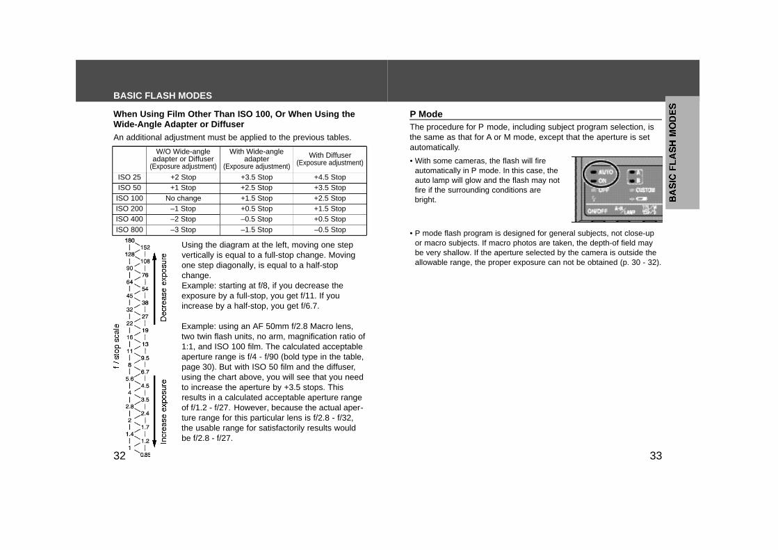
W/O Wide-angleadapter or Diffuser
(Exposure adjustment)
With Wide-angleadapter
(Exposure adjustment)
With Diffuser(Exposure adjustment)
ISO 25 +2 Stop +3.5 Stop +4.5 StopISO 50 +1 Stop +2.5 Stop +3.5 StopISO 100 No change +1.5 Stop +2.5 StopISO 200 –1 Stop +0.5 Stop +1.5 StopISO 400 –2 Stop –0.5 Stop +0.5 StopISO 800 –3 Stop –1.5 Stop –0.5 Stop
The procedure for P mode, including subject program selection, isthe same as that for A or M mode, except that the aperture is setautomatically.
P Mode
• With some cameras, the flash will fireautomatically in P mode. In this case, theauto lamp will glow and the flash may notfire if the surrounding conditions arebright.
• P mode flash program is designed for general subjects, not close-upor macro subjects. If macro photos are taken, the depth-of field maybe very shallow. If the aperture selected by the camera is outside theallowable range, the proper exposure can not be obtained (p. 30 - 32).
An additional adjustment must be applied to the previous tables.
Using the diagram at the left, moving one stepvertically is equal to a full-stop change. Movingone step diagonally, is equal to a half-stopchange.Example: starting at f/8, if you decrease theexposure by a full-stop, you get f/11. If youincrease by a half-stop, you get f/6.7.
Example: using an AF 50mm f/2.8 Macro lens,two twin flash units, no arm, magnification ratio of1:1, and ISO 100 film. The calculated acceptableaperture range is f/4 - f/90 (bold type in the table,page 30). But with ISO 50 film and the diffuser,using the chart above, you will see that you needto increase the aperture by +3.5 stops. Thisresults in a calculated acceptable aperture rangeof f/1.2 - f/27. However, because the actual aper-ture range for this particular lens is f/2.8 - f/32,the usable range for satisfactorily results wouldbe f/2.8 - f/27.
When Using Film Other Than ISO 100, Or When Using theWide-Angle Adapter or Diffuser
BASIC FLASH MODES
32
3534
MANUAL FLASH (M)Normal TTL flash metering automaticallyadjusts the flash intensity to provide theproper exposure for the subject. Manualflash provides a fixed flash intensity irre-spective of the brightness of the subjectand the camera setting.• In manual flash, the maximum flash power
is when the manual flash control is set to1/1. Each step of the flash power levelcorresponds to one aperture stop. Forexample, changing the setting from 1/1 to1/2, or from 1/32 to 1/64 decreases theexposure by one stop.
• Manual flash operates in the camera’s M(manual) mode only. In other modes, TTLmeasuring is selected automatically.
• As manual flash is not affected by thereflectivity of the subject, it is useful forsubjects with extremely high or low reflec-tivity.
1. Select the M mode on the cam-era.
2. Press the TTL/M/test button(TTL/M/ / ) until the M lampglows.
• Each time the button is pressed, theflash modes will change (see nextpage). For test firing and modeling,see page 44 and 45.
TTL flash metering
Manual flash
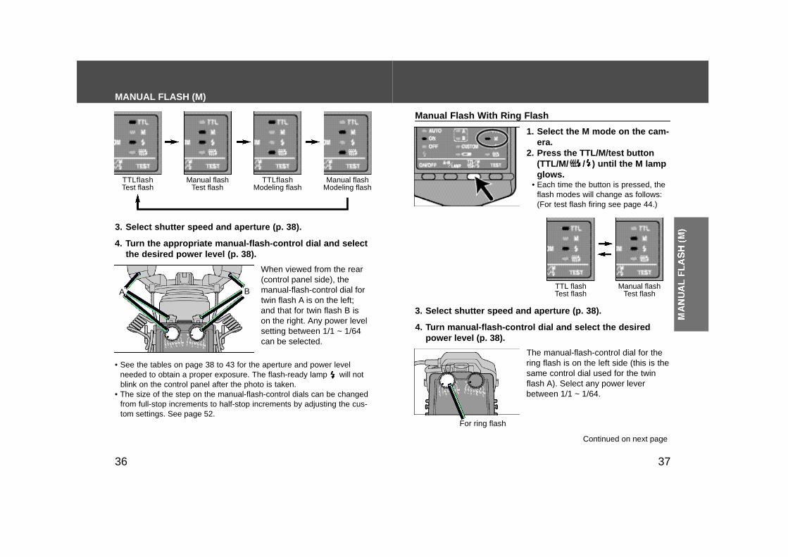
Manual Flash With Twin Flash
DETAILEDOPERATIONS
37
3. Select shutter speed and aperture (p. 38).
4. Turn the appropriate manual-flash-control dial and selectthe desired power level (p. 38).
• See the tables on page 38 to 43 for the aperture and power levelneeded to obtain a proper exposure. The flash-ready lamp will notblink on the control panel after the photo is taken.
• The size of the step on the manual-flash-control dials can be changedfrom full-stop increments to half-stop increments by adjusting the cus-tom settings. See page 52.
When viewed from the rear(control panel side), themanual-flash-control dial fortwin flash A is on the left;and that for twin flash B ison the right. Any power levelsetting between 1/1 ~ 1/64can be selected.
The manual-flash-control dial for thering flash is on the left side (this is thesame control dial used for the twinflash A). Select any power leverbetween 1/1 ~ 1/64.
Manual Flash With Ring Flash
36
1. Select the M mode on the cam-era.
2. Press the TTL/M/test button(TTL/M/ / ) until the M lampglows.
• Each time the button is pressed, theflash modes will change as follows:(For test flash firing see page 44.)
3. Select shutter speed and aperture (p. 38).
4. Turn manual-flash-control dial and select the desiredpower level (p. 38).
TTLflashTest flash
Manual flashTest flash
TTLflashModeling flash
Manual flashModeling flash
TTL flashTest flash
Manual flashTest flash
Continued on next page
MANUAL FLASH (M)
A B
For ring flash

38
AF 50mm f/2.8 Macro (Lens aperture range: f/2.8 - f/32)AF 50mm f/3.5 Macro (Lens aperture range: f/3.5 - f/32)
39
108 (76)
1:1.51:1 1:2 1:3 1:4
1/1
38 (27)1/854 (38)1/4
19 (13)1/3213 (9.5)1/64
27 (19)1/16
76 (54)1/2
54 (38)
19 (13)27 (19)
9.5 (6.7)6.7 (4.5)
13 (9.5)
38 (27)
64
2232
118
16
45
Use aperture values inside ( ) when only one twin flash unit is used.
Magnification Ratio Power level
MANUAL FLASH (M)
• See the tables on pages 38 to 43 for the aperture and power levelneeded to obtain a proper exposure. The flash-ready lamp will notblink on the control panel after the photo is taken.
• The size of the step on the manual-flash-control dials can be changedfrom full-stop increments to half-stop increments by adjusting the cus-tom settings. See page 52.
• The tables beginning on the next page show values for ISO 100speed film without the wide-angle adapter or diffuser. For other ISOfilm speeds, or for the use of the wide-angle adapter or diffuser, adjustthe aperture settings according to the table on page 43. When usingthe twin flash, the data assumes that the power lever is the same forboth units. If they are set at different power levels, see page 42.
• The aperture values given in the tables are calculated values; theactual lens will have its own usable aperture range. Example: using an AF 50mm f/2.8 Macro lens with a pair of twin flashunits with no arm, power level of 1/1, and a magnification ratio of 1:1,the aperture is calculated at f/90 (bold type in the table, page 39).However, the smallest actual aperture possible with this lens is f/32.Therefore, if you set the power level to 1/1, the picture will be overex-posed. But, if you set the power level to 1/8, you will get a correctexposure at f/32 (italic type in the table, page 39).
• These tables show the apertures where the proper exposure of theilluminated area is obtained. Actual exposure varies according to thesubject’s shape or position. Test photographs or bracketing is recom-mended especially when the subject is illuminated from side orbehind.
• The following tables show data for certain lenses and magnificationratios. For other lenses and magnification ratios, see pages 61 and63.
Selecting Apertures and Power Level - Manual Flash -
Ring flash(1 ~ 4 lamps)
1/1
1/81/4
1/321/64
1/16
1/2
1/1
1/81/4
1/321/64
1/16
1/2
1/1
1/81/4
1/321/64
1/16
1/2
180 (128)
64 (45)90 (64)
32 (22)22 (16)
45 (32)
128 (90)90 (64)
32 (22)45 (32)
16 (11)11 (8)
22 (16)
64 (45)128 (90)
45 (32)64 (45)
22 (16)16 (11)
32 (22)
90 (64)128 (90)
45 (32)64 (45)
22 (16)16 (11)
32 (22)
90 (64)
64 (45)
22 (16)32 (22)
11 (8)8 (5.6)
16 (11)
45 (32)90 (64)
32 (22)45 (32)
16 (11)11 (8)
22 (16)
64 (45)90 (64)
32 (22)45 (32)
16 (11)11 (8)
22 (16)
64 (45)108 (76)
38 (27)54 (38)
19 (13)13 (9.5)
27 (19)
76 (54)
16 (11)22 (16)
8 (5.6)5.6 (4)
11 (8)
32 (22)
4 (2.8)
16 (11)22 (16)
8 (5.6)5.6 (4)
11 (8)
32 (22)
4 (2.8)
22 (16)32 (22)
11 (8)8 (5.6)
16 (11)
45 (32)
5.6 (4)
54 (38)
19 (13)27 (19)
9.5 (6.7)6.7 (4.5)
13 (9.5)
38 (27)64 (45)
22 (16)32 (22)
11 (8)8 (5.6)
16 (11)
45 (32)
2738
139.5
19
54
6.7
2232
118
16
45
5.6
76
2738
139.5
19
5476
2738
139.5
19
54
4140
MANUAL FLASH (M)
AF 100mm f/2.8 Macro (Lens aperture range: f/2.8 - f/32)
Use aperture values inside ( ) when only one twin flash unit is used.
AF 200mm f/4 Macro Apo G (Lens aperture range: f/4 - f/32)
Use aperture values inside ( ) when only one twin flash unit is used.
1:1.51:1 1:2 1:3
1/1
1/81/4
1/321/64
1/16
1/2
5.6
2232
118
16
4
Magnification Ratio Power level
Ring flash(1 ~ 4 lamps)
1/1
1/81/4
1/321/64
1/16
1/2
1/1
1/81/4
1/321/64
1/16
1/2
1/1
1/81/4
1/321/64
1/16
1/2
64 (45)
22 (16)32 (22)
11 (8)8 (5.6)
16 (11)
45 (32)
27
139.5
19
1:1.51:1 1:2
1/1
1/81/4
1/321/64
1/16
1/2
Magnification Ratio Power level
Ring flash(1 ~ 4 lamps)
1/1
1/81/4
1/321/64
1/16
1/2
1/1
1/81/4
1/321/64
1/16
1/2
1/1
1/81/4
1/321/64
1/16
1/2
38 (27)54 (38)
19 (13)13 (9.5)
27 (19)
76 (54)
9.5 (6.7)
38 (27)54 (38)
19 (13)13 (9.5)
27 (19)
76 (54)
9.5 (6.7)
64 (45)
22 (16)32 (22)
11 (8)8 (5.6)
16 (11)
45 (32) 38 (27)54 (38)
19 (13)13 (9.5)
27 (19)
9.5 (6.7)6.7 (4.5)
22 (16)32 (22)
11 (8)8 (5.6)
16 (11)
45 (32)
5.6 (4)
64 (45)
22 (16)32 (22)
11 (8)8 (5.6)
16 (11)
45 (32)64 (45)
22 (16)32 (22)
11 (8)8 (5.6)
16 (11)
45 (32)
5.6
2232
118
16
44.53.5
6.7 5.6
22
118
16
42.8
64 (45)
22 (16)32 (22)
11 (8)8 (5.6)
16 (11)
45 (32)22 (16)32 (22)
11 (8)8 (5.6)
16 (11)
45 (32)
5.6 (4)
19 (13)27 (19)
9.5 (6.7)6.7 (4.5)
13 (9.5)
38 (27)
4.5 (3.5)64 (45)
22 (16)32 (22)
11 (8)8 (5.6)
16 (11)
45 (32)
5.6 (4)
22 (16)32 (22)
11 (8)8 (5.6)
16 (11)
45 (32)
19 (13)27 (19)
9.5 (6.7)6.7 (4.5)
13 (9.5)
4.5 (3.5)3.5 (2.4)
19 (13)27 (19)
9.5 (6.7)6.7 (4.5)
13 (9.5)
38 (27)
4.5 (3.5) 5.6 (4)
22 (16)32 (22)
11 (8)8 (5.6)
16 (11)
45 (32)
5.6 (4)
22 (16)32 (22)
11 (8)8 (5.6)
16 (11)
45 (32)
22 (16)32 (22)
11 (8)8 (5.6)
16 (11)
45 (32)
5.6 (4) 5.6 (4)
22 (16)32 (22)
11 (8)8 (5.6)
16 (11)
45 (32) 38 (27)
19 (13)13 (9.5)
27 (19)
9.5 (6.7)6.7 (4.5)4.5 (3.5)
2738
139.5
19
6.74.5
27
139.5
19
4.53.5
6.7 5.6
22
118
16
42.8
64 (45)
22 (16)32 (22)
11 (8)8 (5.6)
16 (11)
45 (32)
4342
MANUAL FLASH (M)
AF Macro Zoom 3X-1X f/1.7-2.8 (Lens aperture range at 1X: f/5.6 - 54,at 3X: f/6.7 - 64)
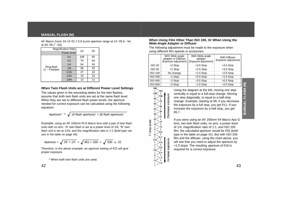
When Twin Flash Units are at Different Power Level SettingsThe values given in the preceding tables for the twin flashes,assume that both twin flash units are set at the same flash level.When they are set to different flash power levels, the apertureneeded for correct exposure can be calculated using the followingequasion:
(A flash aperture)2 + (B flash aperture) 2Aperture*
Example: using an AF 100mm f/2.8 Macro lens with a pair of twin flashunits with no arm. “A” twin flash is set at a power level of 1/8, “B” twinflash unit is set at 1/16, and the magnification ratio is 1:1 (bold type val-ues in the table on page 40).
192 + 132 361 + 169 530=
=
= 22Aperture =
Therefore, in the above example, an aperture setting of f/22 will giveproper exposure.
The following adjustment must be made to the exposure whenusing different film speeds or accesories.
When Using Film Other Than ISO 100, Or When Using theWide-Angle Adapter or Diffuser
Using the diagram at the left, moving one stepvertically is equal to a full-stop change. Movingone step diagonally, is equal to a half-stopchange. Example: starting at f/8, if you decreasethe exposure by a full stop, you get f/11. If youincrease the exposure by a half stop, you getf/6.7.
If you were using an AF 200mm f/4 Macro Apo Glens, two twin flash units, no arm, a power levelof 1/4, magnification ratio of 1:1, and ISO 100film, the calculated aperture would be f/32 (boldtype in the table on page 41). But with ISO 200film and the diffuser, using the chart above, youwill see that you need to adjust the aperture by+1.5 stops. The resulting aperture of f/19 isrequired for a correct exposure.
* When both twin flash units are used.
3X1XMagnification Ratio
Power level
Ring flash(1 ~ 4 lamps)
1/1
1/81/4
1/321/64
1/16
1/2
W/O Wide-angleadapter or Diffuser
(Exposure adjustment)
With Wide-angleadapter
(Exposure adjustment)
With Diffuser(Exposure adjustment)
ISO 25 +2 Stop +3.5 Stop +4.5 StopISO 50 +1 Stop +2.5 Stop +3.5 StopISO 100 No change +1.5 Stop +2.5 StopISO 200 –1 Stop +0.5 Stop +1.5 StopISO 400 –2 Stop –0.5 Stop +0.5 StopISO 800 –3 Stop –1.5 Stop –0.5 Stop
76108
3827
54
1913
4564
2216
32
90
11
4544
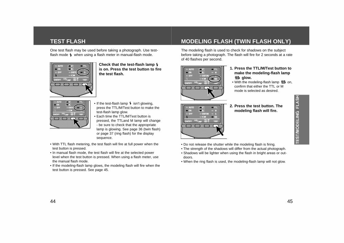
MODELING FLASH (TWIN FLASH ONLY)The modeling flash is used to check for shadows on the subjectbefore taking a photograph. The flash will fire for 2 seconds at a rateof 40 flashes per second.
1. Press the TTL/M/Test button tomake the modeling-flash lamp
glow.• With the modeling-flash lamp on,
confirm that either the TTL or Mmode is selected as desired.
2. Press the test button. Themodeling flash will fire.
• Do not release the shutter while the modeling flash is firing.• The strength of the shadows will differ from the actual photograph.• Shadows will be lighter when using the flash in bright areas or out-
doors.• When the ring flash is used, the modeling-flash lamp will not glow.
TEST FLASHOne test flash may be used before taking a photograph. Use test-flash mode when using a flash meter in manual-flash mode.
Check that the test-flash lampis on. Press the test button to firethe test flash.
• If the test-flash lamp isn’t glowing,press the TTL/M/Test button to make thetest-flash lamp glow.
• Each time the TTL/M/Test button ispressed, the TTLand M lamp will change- be sure to check that the appropriatelamp is glowing. See page 36 (twin flash)or page 37 (ring flash) for the displaysequence.
• With TTL flash metering, the test flash will fire at full power when thetest button is pressed.
• In manual flash mode, the test flash will fire at the selected powerlevel when the test button is pressed. When using a flash meter, usethe manual flash mode.
• If the modeling-flash lamp glows, the modeling flash will fire when thetest button is pressed. See page 45.
4746
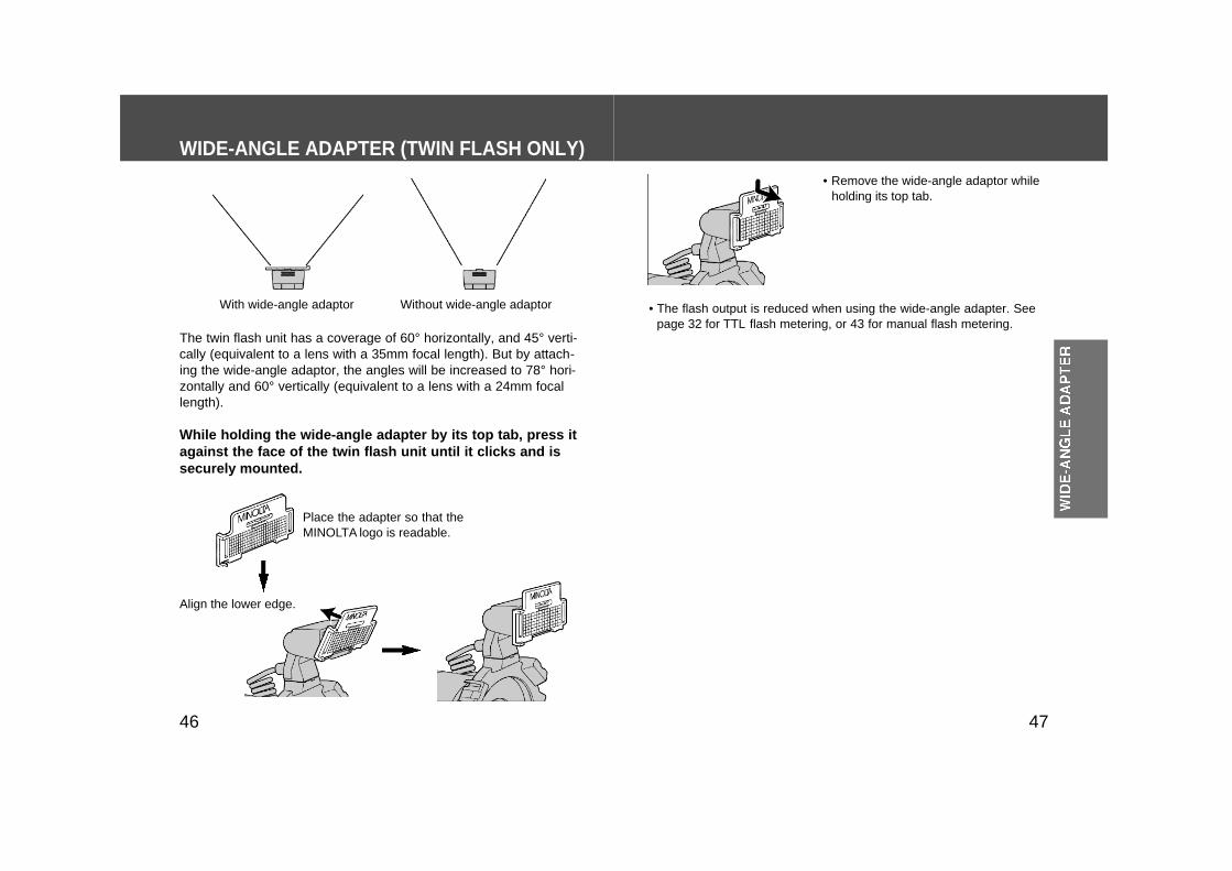
The twin flash unit has a coverage of 60° horizontally, and 45° verti-cally (equivalent to a lens with a 35mm focal length). But by attach-ing the wide-angle adaptor, the angles will be increased to 78° hori-zontally and 60° vertically (equivalent to a lens with a 24mm focallength).
WIDE-ANGLE ADAPTER (TWIN FLASH ONLY)
While holding the wide-angle adapter by its top tab, press itagainst the face of the twin flash unit until it clicks and issecurely mounted.
• Remove the wide-angle adaptor whileholding its top tab.
• The flash output is reduced when using the wide-angle adapter. Seepage 32 for TTL flash metering, or 43 for manual flash metering.
Place the adapter so that theMINOLTA logo is readable.
With wide-angle adaptor Without wide-angle adaptor
Align the lower edge.
4948
Without diffuser
With diffuser
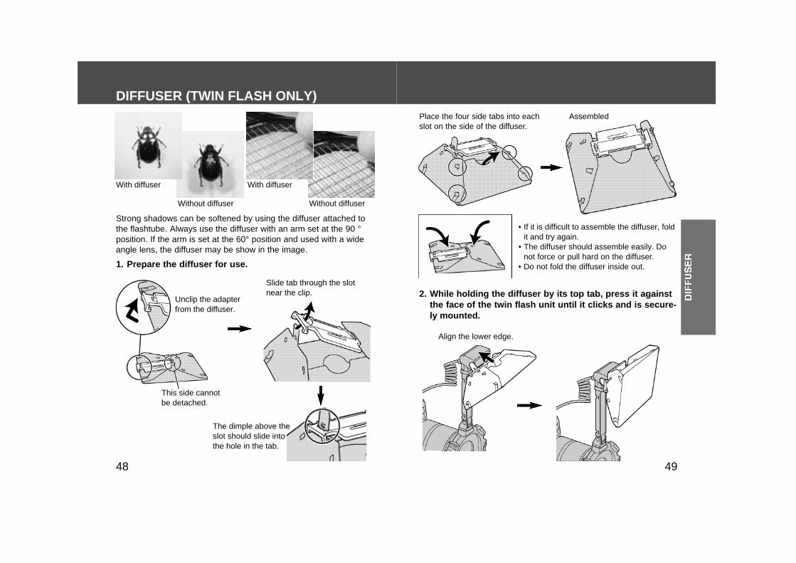
Strong shadows can be softened by using the diffuser attached tothe flashtube. Always use the diffuser with an arm set at the 90 °position. If the arm is set at the 60° position and used with a wideangle lens, the diffuser may be show in the image.
1. Prepare the diffuser for use.
DIFFUSER (TWIN FLASH ONLY)
Slide tab through the slotnear the clip.
Place the four side tabs into eachslot on the side of the diffuser.
• If it is difficult to assemble the diffuser, foldit and try again.
• The diffuser should assemble easily. Donot force or pull hard on the diffuser.
• Do not fold the diffuser inside out.
2. While holding the diffuser by its top tab, press it againstthe face of the twin flash unit until it clicks and is secure-ly mounted.
Align the lower edge.
The dimple above theslot should slide intothe hole in the tab.
Unclip the adapterfrom the diffuser.
This side cannotbe detached.
Without diffuser
With diffuser
Assembled
5150
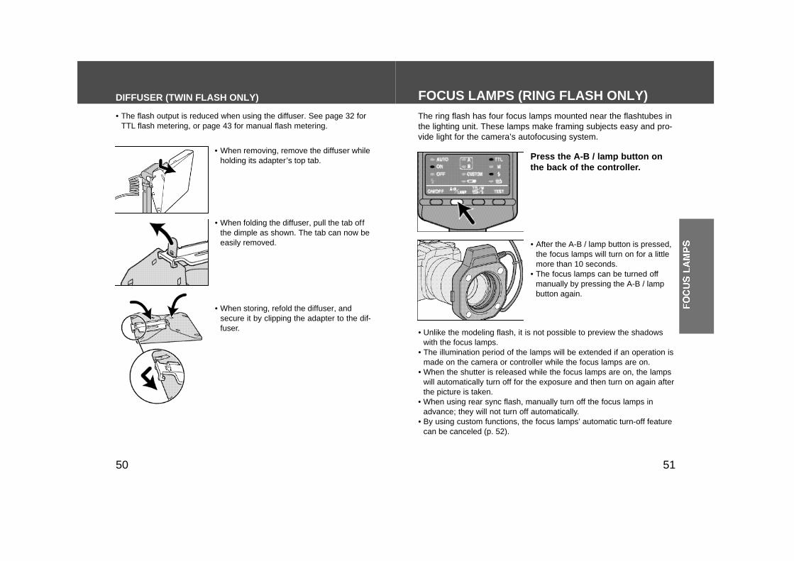
The ring flash has four focus lamps mounted near the flashtubes inthe lighting unit. These lamps make framing subjects easy and pro-vide light for the camera’s autofocusing system.
FOCUS LAMPS (RING FLASH ONLY)
Press the A-B / lamp button onthe back of the controller.
• After the A-B / lamp button is pressed,the focus lamps will turn on for a littlemore than 10 seconds.
• The focus lamps can be turned offmanually by pressing the A-B / lampbutton again.
• Unlike the modeling flash, it is not possible to preview the shadowswith the focus lamps.
• The illumination period of the lamps will be extended if an operation ismade on the camera or controller while the focus lamps are on.
• When the shutter is released while the focus lamps are on, the lampswill automatically turn off for the exposure and then turn on again afterthe picture is taken.
• When using rear sync flash, manually turn off the focus lamps inadvance; they will not turn off automatically.
• By using custom functions, the focus lamps’ automatic turn-off featurecan be canceled (p. 52).
DIFFUSER (TWIN FLASH ONLY)
• When removing, remove the diffuser whileholding its adapter’s top tab.
• When storing, refold the diffuser, andsecure it by clipping the adapter to the dif-fuser.
• The flash output is reduced when using the diffuser. See page 32 forTTL flash metering, or page 43 for manual flash metering.
• When folding the diffuser, pull the tab offthe dimple as shown. The tab can now beeasily removed.
5352
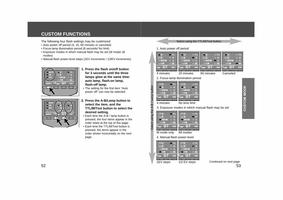
1. Auto power off period
4 minutes
4 minutes No time limit
M mode only All modes
1EV steps 1/2 EV steps
60 minutes15 minutes Canceled
2. Focus-lamp illumination period
3. Exposure modes in which manual flash may be set
4. Manual-flash power-level
Continued on next page
Select using the TTL/M/Test button
CUSTOM FUNCTIONS
1. Press the flash on/off buttonfor 3 seconds until the threelamps glow at the same time:auto lamp, flash-on lamp,flash-off lamp.
• The setting for the first item “Autopower off” can now be selected.
2. Press the A-B/Lamp button toselect the item, and theTTL/M/Test button to select thedesired setting.
• Each time the A-B / lamp button ispressed, the four items appear in theorder listed at the top of this page.
• Each time the TTL/M/Test button ispressed, the items appear in theorder shown horizontally on the nextpage.
The following four flash settings may be custimized:• Auto power off period (4, 15, 60 minutes or canceled)• Focus-lamp illumination period (8 seconds/ No limit)• Exposure modes in which manual flash may be set (M mode/ all
modes)• Manual-flash power-level steps (1EV increments / 1/2EV increments)
5554
APPENDIX
CUSTOM FUNCTIONS
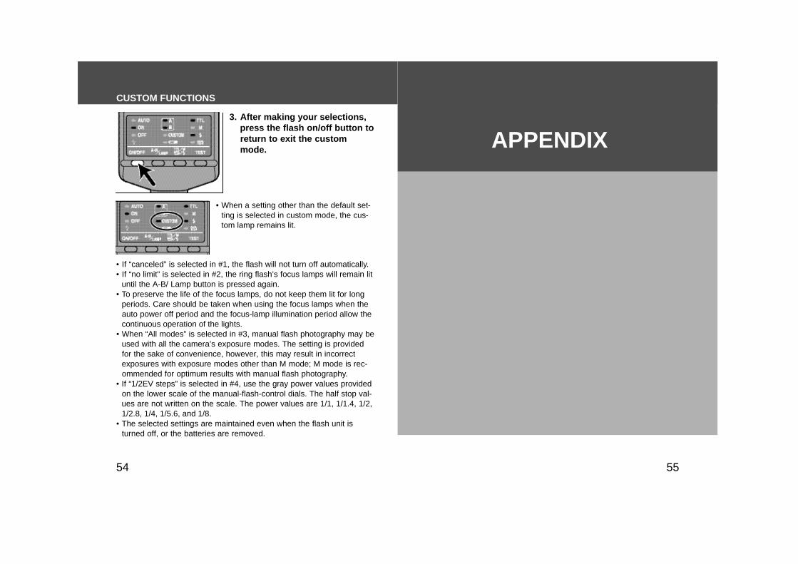
3. After making your selections,press the flash on/off button toreturn to exit the custommode.
• When a setting other than the default set-ting is selected in custom mode, the cus-tom lamp remains lit.
• If “canceled” is selected in #1, the flash will not turn off automatically.• If “no limit” is selected in #2, the ring flash’s focus lamps will remain lit
until the A-B/ Lamp button is pressed again.• To preserve the life of the focus lamps, do not keep them lit for long
periods. Care should be taken when using the focus lamps when theauto power off period and the focus-lamp illumination period allow thecontinuous operation of the lights.
• When “All modes” is selected in #3, manual flash photography may beused with all the camera’s exposure modes. The setting is providedfor the sake of convenience, however, this may result in incorrectexposures with exposure modes other than M mode; M mode is rec-ommended for optimum results with manual flash photography.
• If “1/2EV steps” is selected in #4, use the gray power values providedon the lower scale of the manual-flash-control dials. The half stop val-ues are not written on the scale. The power values are 1/1, 1/1.4, 1/2,1/2.8, 1/4, 1/5.6, and 1/8.
• The selected settings are maintained even when the flash unit isturned off, or the batteries are removed.
5756
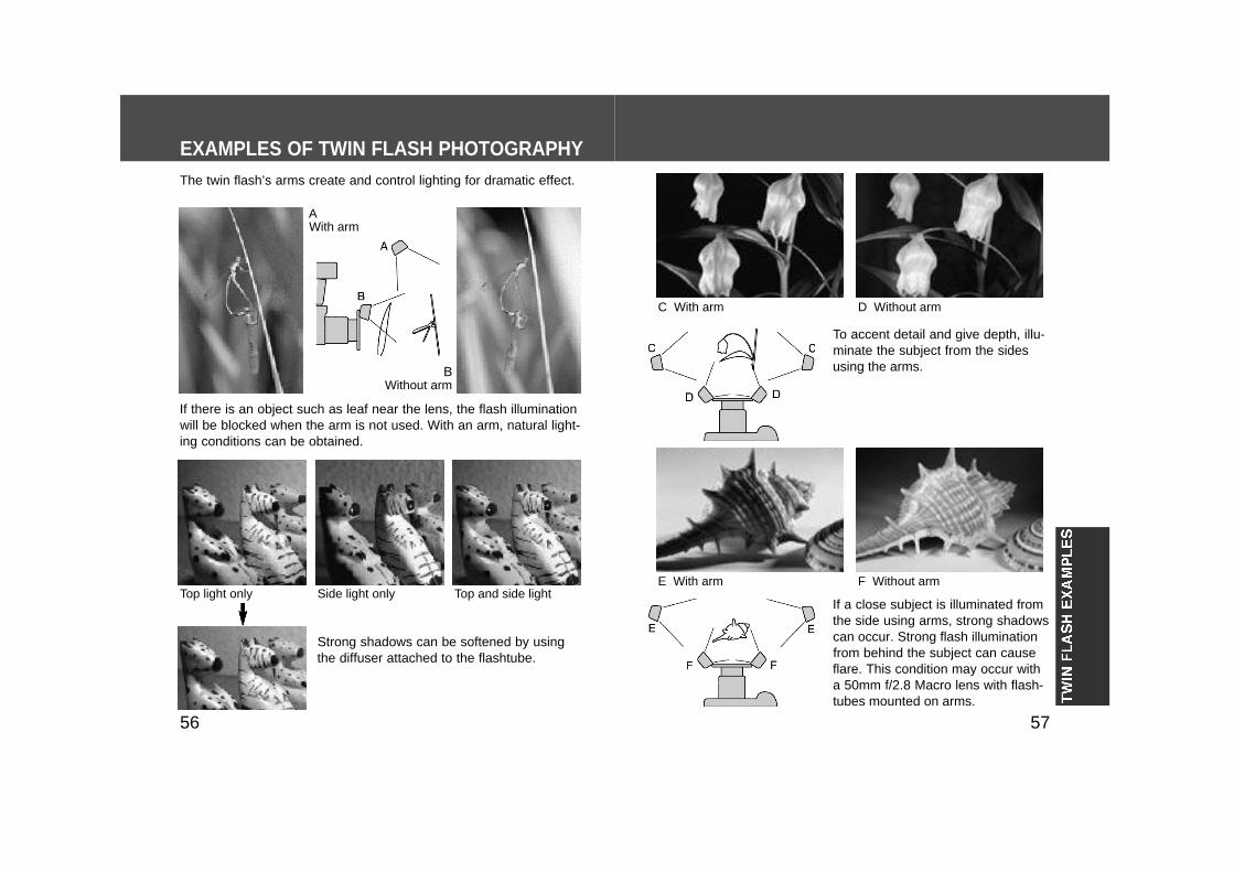
If a close subject is illuminated fromthe side using arms, strong shadowscan occur. Strong flash illuminationfrom behind the subject can causeflare. This condition may occur witha 50mm f/2.8 Macro lens with flash-tubes mounted on arms.
EXAMPLES OF TWIN FLASH PHOTOGRAPHY
C With arm D Without arm
To accent detail and give depth, illu-minate the subject from the sidesusing the arms.
AWith arm
BWithout arm
If there is an object such as leaf near the lens, the flash illuminationwill be blocked when the arm is not used. With an arm, natural light-ing conditions can be obtained.
E With arm F Without armTop light only Side light only Top and side light
Strong shadows can be softened by usingthe diffuser attached to the flashtube.
The twin flash’s arms create and control lighting for dramatic effect.

5958
EXAMPLES OF RING FLASH PHOTOGRAPHYEXAMPLES OF TWIN FLASH PHOTOGRAPHY
Examples of top illumination
Setting Different Power Levels (Manual Flash Only)Different power level settings are possibleusing manual flash operation (p. 35).
Top flash fires at fullpower (1/1), while theother flash adds fill at1/32 power.
With diffusers mounted, the rightflash provides the main illumina-tion (1/2), while the left is used asa fill light at the 1/64 setting.
The ring flash’s four flashtubes render finedetail and are extremely effective for scientif-ic or medical applications. When the subjectis close, the use of one flashtube createsshadows which can add dimension to thesubject.
All flashtubes
All flashtubes Top flashtube
Left flashtube

6160
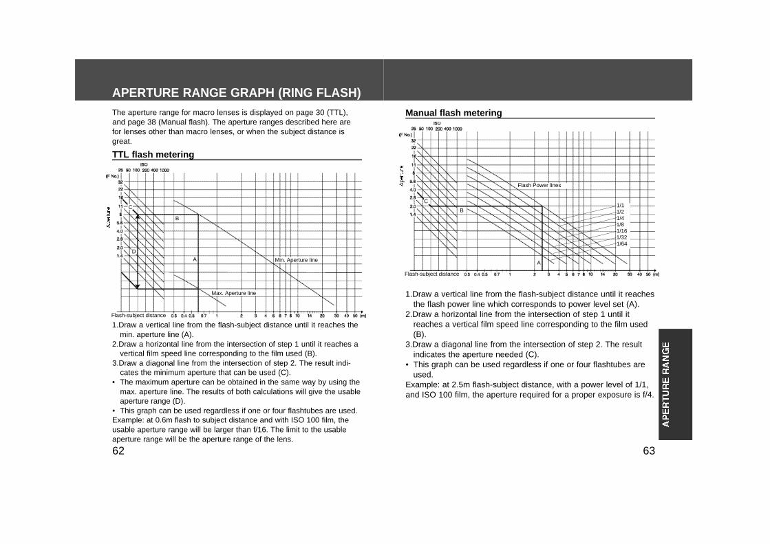
APERTURE RANGE GRAPH (TWIN FLASH)The aperture range for macro lenses is displayed on page 30 (TTL),and page 38 (Manual flash). The aperture ranges described here arefor lenses other than macro lenses, or when the subject distance isgreat.
TTL flash metering
Min. Aperture lines
Max. Aperture lines
A
B
C
Flash-subject distance
1.Draw a vertical line from the flash-subject distance until it reachesthe flash power line which corresponds to power level set (A).
2.Draw a horizontal line from the intersection of step 1 until itreaches a vertical film speed line corresponding to the film used(B).
3.Draw a diagonal line from the intersection of step 2. The resultindicates the aperture needed (C).
• The figures in parenthesis are employed when only one twin flashunit is used.
Example: at 1.5m flash-subject distance, with a power level of 1/1,and ISO 100 film, the aperture required for a proper exposure isf/16.
Manual flash metering
Flash Power lines
A
B
C
Flash-subject distance
1/11/2 (1/1)1/4 (1/2)1/8 (1/4)1/16 (1/8)1/32 (1/16)1/64 (1/32)(1/64)
1.Draw a vertical line from the flash-subject distance until it reaches themin. aperture line (A).
2.Draw a horizontal line from the intersection of step 1 until it reaches avertical film speed line corresponding to the film used (B).
3.Draw a diagonal line from the intersection of step 2. The result indi-cates the minimum aperture that can be used (C).
• The maximum aperture can be obtained in the same way by using themax. aperture line. The results of both calculations will give the usableaperture range (D).
• The dotted lines are employed when only one twin flash unit is used.Example: at 1.5m flash to subject distance and with ISO 100 film, theusable aperture range will be larger than f/16. The limit to the usableaperture range will be the aperture range of the lens.
D
6362
APERTURE RANGE GRAPH (RING FLASH)The aperture range for macro lenses is displayed on page 30 (TTL),and page 38 (Manual flash). The aperture ranges described here arefor lenses other than macro lenses, or when the subject distance isgreat.
1.Draw a vertical line from the flash-subject distance until it reaches themin. aperture line (A).
2.Draw a horizontal line from the intersection of step 1 until it reaches avertical film speed line corresponding to the film used (B).
3.Draw a diagonal line from the intersection of step 2. The result indi-cates the minimum aperture that can be used (C).
• The maximum aperture can be obtained in the same way by using themax. aperture line. The results of both calculations will give the usableaperture range (D).
• This graph can be used regardless if one or four flashtubes are used.Example: at 0.6m flash to subject distance and with ISO 100 film, theusable aperture range will be larger than f/16. The limit to the usableaperture range will be the aperture range of the lens.
TTL flash metering
Min. Aperture line
Max. Aperture line
Flash-subject distance
1.Draw a vertical line from the flash-subject distance until it reachesthe flash power line which corresponds to power level set (A).
2.Draw a horizontal line from the intersection of step 1 until itreaches a vertical film speed line corresponding to the film used(B).
3.Draw a diagonal line from the intersection of step 2. The resultindicates the aperture needed (C).
• This graph can be used regardless if one or four flashtubes areused.
Example: at 2.5m flash-subject distance, with a power level of 1/1,and ISO 100 film, the aperture required for a proper exposure is f/4.
Manual flash metering
Flash Power lines
Flash-subject distance
1/11/21/41/81/161/321/64
A
B
C
D
A
B
C
6564
COMPATIBILITY WITH OTHER PRODUCTSDuring Photography• This flash unit generates strong light, and should therefore not be
used in front of the eyes.
Batteries• Do not store the macro flash controller with the alkaline batteries
inside it. Leakage from the batteries may damage the batterychamber.
• Due to the characteristics of alkaline batteries, temperature, andstorage conditions, the lamp may glow temporarily. The dis-played battery level will be restored to the correct value after theflash has been used a few times. When the lamp blinks toindicate that the flash cannot be used, pressing the flash on/offbutton in number of times may result in recovery of the battery.Replace the battery if it does not recover.
• When using the lithium batteries, if the batteries become hot dueto high temperature or successive use, the lamp may blinkand the flash may not be able to use for a while. Wait until the bat-teries become cold before using the flash again.
• Nickel-metal hydride batteries can lose power suddenly. If thelamp starts to glow or flash can no longer be used while tak-ing pictures, change or recharge the batteries.
• Depending on the time elapsed since manufacture of the battery,the recycling time and number of flashes for new batteries maydiffer from the values shown in the table.
CARE AND STORAGECamera• If you are using Maxxum/Minolta 9000, 7000, or 5000, the optional
Flash Shoe Adapter FS-1200 is necessary. See the FS-1200 man-ual for details.
Lenses• Macro Twin Flash 2400 contains adapter rings for 49mm and
55mm diameter lenses. To use a 72mm diameter lens such as anAF 200mm f/4 Macro Apo G, the optional 72mm Twin FlashAdapter Ring (AR-T72) is required. If you use a 62mm diameterlens, both the 72mm adapter ring and the 62mm to 72mm step-upring are required.
• Macro Ring Flash 1200 contains adapter rings for 49mm and55mm diameter lenses. To use an AF 200mm f/4 Macro Apo G,the optional Macro Flash Adapter (for 200mm Macro) is required.Other lenses cannot be used.
For both the Twin Flash and Ring Flash:• Lenses whose barrels rotate when autofocusing cannot be used.• Lens diameters of 46mm (V 50mm f/3.5 Macro) require the 46mm
to 49mm step-up ring.
For the Twin Flash only:The holder may vignette the picture if a wide focal-length lens isused. Do not use lenses whose focal length is shorter than 24mm.Contact an authorized Minolta Service Facility if the focal length isbetween 24mm and 27mm.
For the Ring Flash only:The flash may vignette the picture if a wide focal-length lens isused. Do not use lenses whose focal length is shorter than 50mm.
6766
Maintenance• Clean by wiping with a soft, clean cloth. If the product has been in
contact with sand, wiping will damage the surface, and it shouldtherefore be cleaned gently using a blower.
• Do not use cleaners containing organic solvents (eg. thinners orbenzene) under any circumstances.
Questions and Service• If you have questions about this product, contact your local cam-
era dealer or write to the Minolta distributor in your area.• Before shipping your product, please contact an authorized
Minolta Service Facility for details.
CARE AND STORAGE
Temperature• This product may be used over a temperature range of –20°C to
50°C.• Do not leave this product exposed extremely high temperatures
(eg. direct sunlight inside motor vehicles), or in conditions of highhumidity.
• To prevent condensation from forming, place the product in asealed plastic bag when bringing it from cold environment to awarm environment. Allow it to come to room temperature beforeremoving it from the bag.
• Battery capacity decreases at colder temperatures. Keep yourflash and spare batteries in a warm inside pocket when shootingin cold weather. The lamp may glow even when there issome power left in the batteries in cold weather. Batteries willregain some of their capacity when warmed to normal operatingtemperature.
• This product is not waterproof. Care is therefore required toensure that it does not come into contact with water or sand whenused near water. Contact with water, sand, dust, or salt contentmay result in a malfunction.
4 tubes
6968
40 continuous cycles of 5 flashes per second(Power level 1/32, nickel-metal hydride battery)
Continuousflash perfor-mance
TTL direct metering, manual flash, or flash controlusing a pre-flash (only used with certain Minolta digitalcameras)
Flash control
Controller 68 x 123 x 91 mm / 2.7 x 4.8 x 3.6 in.Twin flash 43 x 41 x 37 mm / 1.7 x 1.6 x 1.5 in.Ring flash 98 x 121 x 22 mm / 3.9 x 4.8 x 0.9 in.
Size(W x H x D)
Controller 245 g / 8.6 oz. (without batteries)Twin flash 30 g / 1.1 oz. (per twin flash unit)Ring flash 120 g / 4.2 oz.
Weight
Flash coverage
Vertical
Horizontal
Twinflash
Wide-angleAdapter Diffuser
45° 60° 90° 80°
60° 78° 90° 80°
Specifications are based on the latest information available at the timeof printing and are subject to change without notice.
17 24 11 712 17 8 5
2.1 3 1.4 0.9
8.5 12 5.6 3.56 8.5 4 2.5
4.2 6 2.8 1.83 4.2 2 1.3
Power level
1/11/21/41/8
1/161/321/64
1 tube 2 tubesWide-angle
adapterDiffuser
Twin flash(ISO 100)
Guide Number
1.5 1.3
6 58.5 712 10
4.2 3.53 2.5
2.1 1.8
Power level
1/11/21/41/81/161/321/64
1 tubeRing flash(ISO 100)
LithiumAlkaline
0.2~6Recycling time (sec)
Number of flashes*
Nickel-hydride
0.2~6 0.2~5
150 ~ 3000500 ~ 10000200 ~ 4000
Recycling time/Number of flashes
SPECIFICATIONS
Wide angle adapter and diffuser is for one tube.
Ringflash
* For every new battery set
Controller Accessories
7170
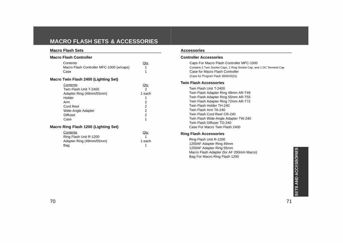
MACRO FLASH SETS & ACCESSORIES
Macro Flash ControllerContentsMacro Flash Controller MFC-1000 (w/caps)Case
Macro Flash Sets
Qty.11
Macro Twin Flash 2400 (Lighting Set)ContentsTwin Flash Unit T-2400Adapter Ring (49mm/55mm)HolderArmCord ReelWide-Angle AdapterDiffuserCase
Qty.2
1 each122221
Macro Ring Flash 1200 (Lighting Set)ContentsRing Flash Unit R-1200Adapter Ring (49mm/55mm)Bag
Qty.1
1 each1
Caps For Macro Flash Controller MFC-1000Contains 2 Twin Socket Caps, 1 Ring Socket Cap, and 1 DC Terminal Cap
Case for Macro Flash Controller(Case for Program Flash 3600HS(D))
Accessories
Twin Flash AccessoriesTwin Flash Unit T-2400Twin Flash Adapter Ring 49mm AR-T49Twin Flash Adapter Ring 55mm AR-T55Twin Flash Adapter Ring 72mm AR-T72Twin Flash Holder TH-240Twin Flash Arm TA-240Twin Flash Cord Reel CR-240Twin Flash Wide-Angle Adapter TW-240Twin Flash Diffuser TD-240Case For Macro Twin Flash 2400
Ring Flash AccessoriesRing Flash Unit R-12001200AF Adapter Ring 49mm1200AF Adapter Ring 55mmMacro Flash Adapter (for AF 200mm Macro)Bag For Macro Ring Flash 1200
© 2000 Minolta Co., Ltd. under the BerneConvention and universal Copyright Convention
Printed in Japan 9222-8843-11 P-A102


![[ITA] Macro Media - Flash 8](https://img.pdfslide.us/doc/110x75/5571fd5b497959916998e91c/ita-macro-media-flash-8.jpg)