Embed Size (px)
Citation preview
21394653
Mack
®
21394653
© Mack Trucks, Inc. 2010 Printed in U.S.A.
MAINTENANCE
21394653April 2010
AND LUBRICATIONMAINTENANCE
MP7, MP8, and MP10 Engines
AND LUBRICATION
MAINTENANCE AND LUBRICATION
MP7, MP8, and MP10 Engines


ContentsOperator’s Manual Vehicle Maintenance CXU, CHU, GU, TD, MRU and LEU ... 1Foreword .............................................................................................. 1Warning Label Information........................................................................ 1General Information ................................................................................ 3Information For the Owner ........................................................................ 3Federal Emission Requirements .................................................................. 5Label Information .................................................................................. 12Safety Information ................................................................................. 19Proper Maintenance Procedure .................................................................. 19Injury Prevention ................................................................................... 22Engine Damage Prevention....................................................................... 30Electric System Damage Prevention............................................................ 32Reporting Safety Defects ......................................................................... 34General Engine Information...................................................................... 35Engine Overview, MP7 and MP8 Left Side View ........................................... 35Engine Overview, MP7 and MP8 Right Side View.......................................... 36Engine Overview, MP10 Left Side View ...................................................... 37Engine Overview, MP10 Right Side View .................................................... 38Electrical System ................................................................................... 39Batteries .............................................................................................. 39Battery Warmer ..................................................................................... 41Battery Condition................................................................................... 41Charging.............................................................................................. 42Load Test ............................................................................................. 44Electrical Connection Protection ................................................................ 44Precautions When Installing Electrical Equipment .......................................... 47Engine Storage ...................................................................................... 50Engine Storage ...................................................................................... 50Maintenance and Service ......................................................................... 51Maintenance Hazards.............................................................................. 51Engine Components, Service Schedules ....................................................... 51Cooling System ..................................................................................... 54Fuel System.......................................................................................... 63Engine Oil............................................................................................ 75Engine Air Filter.................................................................................... 82Exhaust After-Treatment System................................................................ 85Drive Belt Replacement Intervals ............................................................... 94Automatic Belt Tensioner Maintenance...................................................... 102Turbocharger and Charge Air Cooler......................................................... 106Preventive Maintenance Air Suspensions ................................................... 109Steering and Brakes Maintenance............................................................. 110Tires, Wheels and Hub Maintenance ......................................................... 114Chassis Maintenance............................................................................. 128Cab Maintenance ................................................................................. 130Lubrication......................................................................................... 136Oil Capacity Tables and Viscosity Charts ................................................... 142Service Check List ............................................................................... 146
Preventive Maintenance......................................................................... 146Service Charts..................................................................................... 150Scheduled Services............................................................................... 150Tire Record ........................................................................................ 154Fuel and Oil Record.............................................................................. 155Engine Data........................................................................................ 156Literature ........................................................................................... 157Service Assistance and Manuals .............................................................. 157CUSTOMER SERVICE ........................................................................ 158

Operator’s Manual Vehicle Maintenance CXU,CHU, GU, TD, MRU and LEU 1
ForewordDO NOT Remove this manual from the vehicle. It contains important operationaland safety information that is needed by all drivers and owners of this vehicle.
This manual contains information concerning the safe operation of your vehicle. It isextremely important that this information is read and understood before the vehicle isoperated. This manual also contains a considerable amount of information concerningthe vehicle, such as vehicle identification, Preventive Maintenance recommendationsand a log for your service records. Please keep this in the vehicle at all times.Information from other component manufacturers is supplied in separate manualsin the Owners Package.
Note: It is important that this manual stay with the vehicle when it is sold. Importantsafety information must be passed on to the new customer. The service informationcontained in this manual gives the owner important information about maintainingthe vehicle but is not intended as a substitute for the Preventive Maintenance ServiceManual and must not be regarded as such.
The National Highway Traffic Safety Administration (NHTSA) and MACK Inc.should be informed immediately if you believe that the vehicle has a defect that couldcause a crash, injury or death.
Contact NHTSA by calling the Auto Safety Hotline at 1 (888) 327-4236, by writing toNHTSA, U.S. Department of Transportation, Washington, DC 20590, by TTY at 1(800) 424-9153, or visit their website at www.nhtsa.dot.gov.
MACK Trucks, Inc.Greensboro, NC USAOrder number: PV776-21394653
All rights reserved. No part of this publication may be reproduced, stored inretrieval system, or transmitted in any forms by any means, electronic, mechanical,photocopying, recording or otherwise, without the prior written permission of MACKInc.
Warning Label Information
IMPORTANT: Before driving this vehicle, be certain that you have read and thatyou fully understand each and every step of the driving and handling informationin this Operators Manual. Be certain that you fully understand and follow allsafety warnings. It is extremely important that this information is read andunderstood before the vehicle is operated.
IT IS IMPORTANT THAT THE FOLLOWING INFORMATION CONCERNINGLABELS BE READ, UNDERSTOOD AND ALWAYS FOLLOWED.
2 Operator’s Manual Vehicle Maintenance CXU,CHU, GU, TD, MRU and LEU
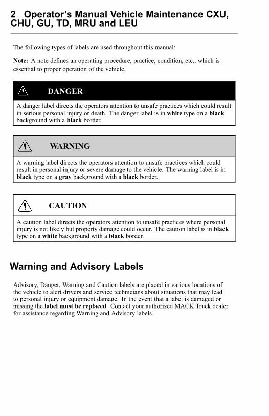
The following types of labels are used throughout this manual:
Note: A note defines an operating procedure, practice, condition, etc., which isessential to proper operation of the vehicle.
DANGER
A danger label directs the operators attention to unsafe practices which could resultin serious personal injury or death. The danger label is in white type on a blackbackground with a black border.
WARNING
A warning label directs the operators attention to unsafe practices which couldresult in personal injury or severe damage to the vehicle. The warning label is inblack type on a gray background with a black border.
CAUTION
A caution label directs the operators attention to unsafe practices where personalinjury is not likely but property damage could occur. The caution label is in blacktype on a white background with a black border.
Warning and Advisory Labels
Advisory, Danger, Warning and Caution labels are placed in various locations ofthe vehicle to alert drivers and service technicians about situations that may leadto personal injury or equipment damage. In the event that a label is damaged ormissing the label must be replaced. Contact your authorized MACK Truck dealerfor assistance regarding Warning and Advisory labels.
Operator’s Manual Vehicle Maintenance CXU,CHU, GU, TD, MRU and LEU 3
General InformationInformation For the Owner
If there are questions on the maintenance and performance of your vehicle, pleasediscuss them with your MACK Truck dealer. Your authorized dealer is required tohave trained mechanics, special tools and spare parts to fully service your vehicle.If necessary, your dealer will contact MACK Inc. or other manufacturers for anyassistance.
In addition to this Maintenance Manual, there may be additional instruction/operatorsmanuals supplied by component manufacturers. These manuals are placed in theOwners Package and placed in the cab. Be sure to read all the manuals thoroughlybefore operating the vehicle.
Also, various safety labels may be placed on components by the componentmanufacturer. Be sure to read and follow these labels to prevent damage to thevehicle, personal injury or even death.
Information in this manual refers to MACK components and MACK drivetrain.
Establish a Preventive Maintenance Program with the help of your local MACKTruck dealer. A Preventive Maintenance Program makes it possible to maximizethe amount of time your vehicle is up and running, resulting in longer componentlife. This makes for a safer vehicle by reducing any mechanical failures due to poormaintenance practices.
Note: Federal law requires manufacturers to notify owners of its products in the eventof a Federal Motor Vehicle Safety Standard or if a safety related defect is discovered.If you are not the original owner of this vehicle, please notify us about the change inownership at the address below or through an authorized MACK Truck dealer. This isthe only way we will be able to contact you if necessary.MACK Inc.Northeast Region7900 National Service Road, Mail: P.O. Box 26259Greensboro, NC 27402TEL: (336) 291-9001United States of America
This Maintenance Manual covers all MACK vehicles manufactured by MACK Inc.,including the whole chassis and all MACK manufactured components. For specificmaintenance information on vendor components, see the respective manufacturersservice and maintenance literature.
This manual, together with manuals for specific components contain importantinformation to be able to operate this vehicle safely. They contain advice and

4 Operator’s Manual Vehicle Maintenance CXU,CHU, GU, TD, MRU and LEU
instructions which will enable you to get the operating economy and performancethat you expect from this quality vehicle.
All information, illustrations and specifications contained in this manual are basedupon the latest product information available at the time of publication. If anyquestions arise concerning the current status of Federal or state laws, the appropriateFederal or state agency should be contacted.
Note: Illustrations are used for reference only and may differ slightly from the actualvehicle, however, key components addressed in this manual are represented asaccurately as possible.
MACK Inc. reserves the right to make changes at any time or to change specificationsor design without notice and without incurring obligation.
General
USAThe Federal Clean Air Act, Section 203 (a) (3), states the following concerning theremoval of air pollution control devices or modification of a certified engine to anon-certified configuration:CAA, Section (a) (3) (A) prohibits any person from removing or rendering inoperativeany emission control device or element of design installed on or in a motor vehicleor motor vehicle engine in compliance with federal regulations under the Clean AirAct prior to the sale and delivery of the vehicle to the ultimate purchaser. The statutealso prohibits any person from knowingly removing or rendering inoperative anyemission control device or element of design after sale and delivery of a vehicle orengine to the ultimate purchaser. Any person who violates these provisions eitherby removing or rendering inoperative emissions control devices prior to the sale ordelivery of an engine or vehicle to an ultimate purchaser, or by knowingly removingor rending inoperative such devices after the sale and delivery of an engine or vehicleto an ultimate purchaser, can be subject to penalties of up to $3,750 per incident.Any dealer or manufacturer who violates these provisions can be subject to penaltiesof up to $37, 500 per incident.
Canada
The same conditions that apply in the USA apply to Canada, with one exception.After the vehicle is sold to a retail customer, that is, the end user, the jurisdictioncontrolling the emission control devices becomes the province in which the vehicle islicensed. No changes should be made that render any or all of the devices inoperative.
Should the owner/operator wish to make any changes to the emission control devices,check with the provincial authority before making any such changes.
Operator’s Manual Vehicle Maintenance CXU,CHU, GU, TD, MRU and LEU 5
Mexico
The same conditions that apply in the USA apply to Mexico. Refer to the MexicanFederal Law for Emission Control which adheres to EPA regulations. No changesshould be made that render any or all of the emissions control devices inoperative.
Should the owner/operator wish to make any changes to the emission control devices,check with the state authority before making any such changes.
Federal Emission Requirements
This section covers the requirement of the United States Clean Air Act which states:
The manufacturer shall furnish with each new motor vehicle or motor vehicle enginesuch written instructions for the maintenance and use of the vehicle or engine bythe ultimate purchaser as may be reasonable and necessary to assure the properfunctioning of emission control devices and systems.
This section also covers the requirements of the emissions regulations promulgatedunder the Motor Vehicle Safety Act in Canada.
6 Operator’s Manual Vehicle Maintenance CXU,CHU, GU, TD, MRU and LEU
Tampering with Gaseous Emission ControlSystems ProhibitedThe Federal Clean Air Act prohibits the removal or rendering inoperative of anydevice or element of design installed on or in a motor vehicle or motor vehicle enginein compliance with Federal Emission Regulations by:
1 Any person prior to its sale and delivery to the ultimate purchaser, or2 Any manufacturer or distributor after its sale and delivery to the ultimate purchaser,
or3 Any person engaged in the business of repairing, servicing, selling, leasing, or
trading motor vehicles or motor vehicle engines following its sale and deliveryto the ultimate purchaser, or
4 Any person who operates a fleet of motor vehicles following its sale and deliveryto the ultimate purchaser.
Note: For specifics of the prohibited vehicle/engine modifications refer to the MACKBodybuilder documentation.
Engines Other than MACKFor specific information on engines other than MACK, refer to the enginevendors publications.
Noise Emissions
MACK Inc. warrants to the first person who purchases this vehicle for purposes otherthan resale and to each subsequent purchaser, that this vehicle as manufactured byMACK Inc. was designed, built and equipped to conform, at the time it left the controlof MACK Inc., with all applicable U.S. EPA Noise Control Regulations.
This warranty covers this vehicle as designed, built and equipped by MACK Inc., andis not limited to any particular part, component or system of the vehicle manufacturedby MACK Inc. Defects in design, assembly or in any part, component or system ofthe vehicle as manufactured by MACK Inc., which, at the time it left the control ofMACK Inc. caused noise emissions to exceed Federal standards, are covered bythis warranty for the life of the vehicle.
Operator’s Manual Vehicle Maintenance CXU,CHU, GU, TD, MRU and LEU 7
Noise Control System, Operator Inspection and MaintenanceRequirements
A Noise Control System Maintenance Log is located in this manual. This log shouldbe used to document all Noise Control System related maintenance, whether themaintenance results from a specific noise control system inspection, or a deficiencyidentified during another general maintenance event.
If additional log space is needed, further entries may be added on a separate sheet ofpaper. Store these additions with the main log to preserve a comprehensive record. Itis recommended that copies of all noise emissions related maintenance invoices beretained.
The following Noise Control System inspection and maintenance instructions containsuggested maintenance intervals. These intervals may need adjustment in order tobest accommodate the specific vehicle usage. The following instructions only concernNoise Emissions related items and do not address or modify any general vehiclemaintenance requirements.
The following elements make up the Noise Control System:
• Noise Shielding and Insulation Devices• Cooling System• Exhaust System/DPF System• Air Intake/Air Induction System• Engine Control, EGR and Fuel Systems• Selective Catalytic Reduction (SCR)
Tampering with Noise Control System
Federal law prohibits the following acts or the causing thereof:
(1) The removal or rendering inoperative by any person, other than for purposes ofmaintenance, repair, or replacement, of any device or element of design incorporatedinto any new vehicle for the purpose of noise control prior to its sale or delivery to theultimate purchaser or while it is in use;
or
(2) the use of the vehicle after such device or element of design has been removedor rendered inoperative by any person.
Among the acts that constitute tampering are the acts listed below:
• Removal, or rendering inoperative, of any exhaust components, including mufflers,heavy or double-wall exhaust tubing, flexible tubing or exhaust pipe clamping.
8 Operator’s Manual Vehicle Maintenance CXU,CHU, GU, TD, MRU and LEU
• Removal, or rendering inoperative, of the temperature-modulated cooling fansystem.
• Removal of the cooling fan shroud.• Removal, or rendering inoperative, of the air cleaner or air intake in-line silencer.• Removal of the sound deadening material from the hood or cab tunnel.• Removal, or rendering inoperative, of the engine speed governor so as to allow
engine speed to exceed the manufacturers specifications.• Removal of splash shields located inside the wheel housings.• Removal of engine block shields.• Removal of engine crankcase shields or insulation.• Removal of insulated rocker arm covers.• Removal of transmission noise shields.
Noise Shielding and Insulation DevicesMaintenance
Ensure sound shielding and insulating devices are intact. Inspect components fordamage. Primary system components requiring noise related inspection include thehood, engine compartment insulating materials (including hood insulation, bulkheadinsulation, doghouse insulation, etc.) splash shields, cab skirts, fender shields, andbody panels. Inspect all related fasteners, brackets, and clamps for damage andtightness.
Regulatory Compliance
Acts that constitute tampering with the Noise Shielding and Insulation Devices:
Removing or rendering inoperative the engine and/or transmission noise deadeningpanels, shields or insulating materials.
Removing or rendering inoperative the cab-tunnel or hood noise insulating materials.
Removing or rendering inoperative any vehicle body mounted sound insulationcomponents and/or shields (cab or fender shields, skirts, wheel housing splash shields,etc.).

Operator’s Manual Vehicle Maintenance CXU,CHU, GU, TD, MRU and LEU 9
Cooling System
WARNING
DO NOT work near the fan with the engine running or the ignition in the ONposition. The engine fan can engage at any time without warning. Anyone nearthe fan when it turns on could be seriously injured.
Maintenance
Visually inspect cooling system components for damage, and/or misalignment.
Primary system components requiring noise related inspection include fan blades, fanclutch, fan shroud, fan ring, and recirculation shields. Check fan blades, fan ring, fanshroud, belt tensioner and recirculation shields for any damage. Verify that fan bladesclear the fan ring. Inspect all related fasteners, brackets, and clamps for damage andtightness. Confirm operation of temperature modulated fan clutch.
Regulatory Compliance
Acts that constitute tampering with the Cooling System:
Removing or rendering inoperative cooling system components (such as thetemperature modulated fan clutch, fan shroud, fan ring, recirculation shields, etc.).
Exhaust System
WARNING
Hot engine! Avoid all movable parts or hot engine parts, exhaust gases, and/orfluids. A hot engine, exhaust, and/or fluids can cause burns.
10 Operator’s Manual Vehicle Maintenance CXU,CHU, GU, TD, MRU and LEU
Maintenance
Make sure the exhaust system is intact. Inspect for damage, misalignment and/orleakage. Primary system components requiring noise related inspection includeexhaust manifold, turbocharger, and all exhaust system (rigid and flexible) piping.Closely check the system for exhaust leaks. Special attention should be given to allwelds, seams, gaskets, support points, clamps, couplings and connections.
Inspect all exhaust system fasteners, brackets, and clamps for damage and tightness.
Regulatory Compliance
Acts that constitute tampering with the Exhaust System:
Removing or rendering inoperative exhaust system components (such as the pipes,clamps, etc.).
Air Intake/Air Induction SystemMaintenance
Make sure the air intake system is intact. Inspect components for damage,misalignment and/or leakage. Primary system components requiring noise relatedinspection include the air cleaner housing, air cleaner element, turbocharger, chargeair cooler and intake manifold.
Also inspect all ducts, pipes, hoses, tubing and elbows used to interconnect thesystem. Special attention should be given to all welds, seams, gaskets, support points,clamps, couplings and connections.
Inspect all intake system fasteners, brackets, and clamps for damage and tightness.
Regulatory Compliance
Acts that constitute tampering with the Air Intake/Air Induction System:
Removing or rendering inoperative air intake/induction system components (filter,filter housings, ducts, etc.).
Operator’s Manual Vehicle Maintenance CXU,CHU, GU, TD, MRU and LEU 11
Engine Control, EGR and Fuel Systems
Acts that constitute tampering with Engine Control, EGR and Fuel Systems:
Removing rendering inoperative, or modifying the engine control system such asthe ECU, EGR system components, or fuel system components, in order to allowthe engine to operate outside of the manufacturers specifications is not allowed andviolates both warranty and legislation.
12 Operator’s Manual Vehicle Maintenance CXU,CHU, GU, TD, MRU and LEU
Label Information
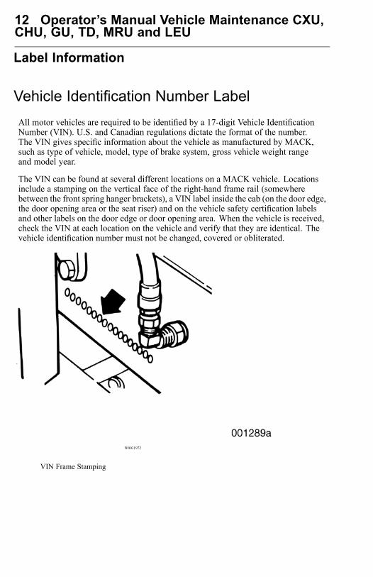
Vehicle Identification Number LabelAll motor vehicles are required to be identified by a 17-digit Vehicle IdentificationNumber (VIN). U.S. and Canadian regulations dictate the format of the number.The VIN gives specific information about the vehicle as manufactured by MACK,such as type of vehicle, model, type of brake system, gross vehicle weight rangeand model year.
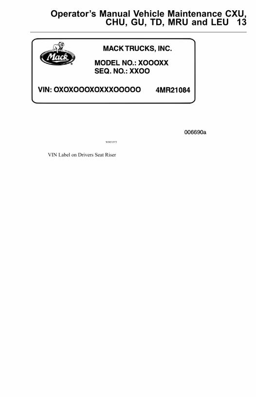
The VIN can be found at several different locations on a MACK vehicle. Locationsinclude a stamping on the vertical face of the right-hand frame rail (somewherebetween the front spring hanger brackets), a VIN label inside the cab (on the door edge,the door opening area or the seat riser) and on the vehicle safety certification labelsand other labels on the door edge or door opening area. When the vehicle is received,check the VIN at each location on the vehicle and verify that they are identical. Thevehicle identification number must not be changed, covered or obliterated.
W0031972
VIN Frame Stamping
Operator’s Manual Vehicle Maintenance CXU,CHU, GU, TD, MRU and LEU 13
W0031973
VIN Label on Drivers Seat Riser
14 Operator’s Manual Vehicle Maintenance CXU,CHU, GU, TD, MRU and LEU
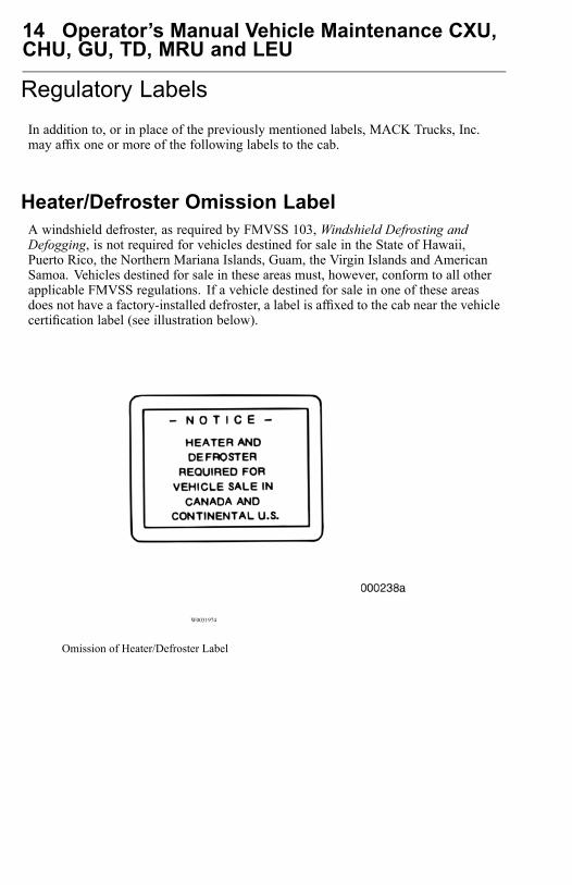
Regulatory LabelsIn addition to, or in place of the previously mentioned labels, MACK Trucks, Inc.may affix one or more of the following labels to the cab.
Heater/Defroster Omission LabelA windshield defroster, as required by FMVSS 103, Windshield Defrosting andDefogging, is not required for vehicles destined for sale in the State of Hawaii,Puerto Rico, the Northern Mariana Islands, Guam, the Virgin Islands and AmericanSamoa. Vehicles destined for sale in these areas must, however, conform to all otherapplicable FMVSS regulations. If a vehicle destined for sale in one of these areasdoes not have a factory-installed defroster, a label is affixed to the cab near the vehiclecertification label (see illustration below).
W0031974
Omission of Heater/Defroster Label
Operator’s Manual Vehicle Maintenance CXU,CHU, GU, TD, MRU and LEU 15
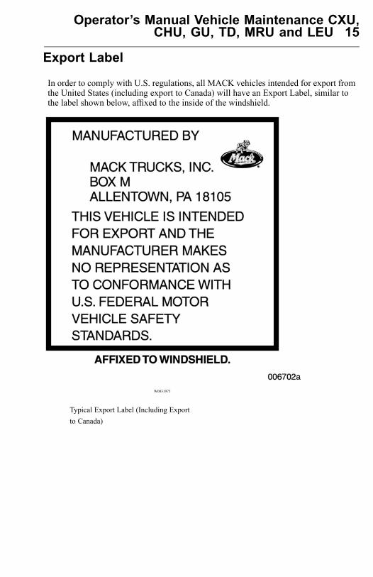
Export Label
In order to comply with U.S. regulations, all MACK vehicles intended for export fromthe United States (including export to Canada) will have an Export Label, similar tothe label shown below, affixed to the inside of the windshield.
W0031975
Typical Export Label (Including Exportto Canada)
16 Operator’s Manual Vehicle Maintenance CXU,CHU, GU, TD, MRU and LEU
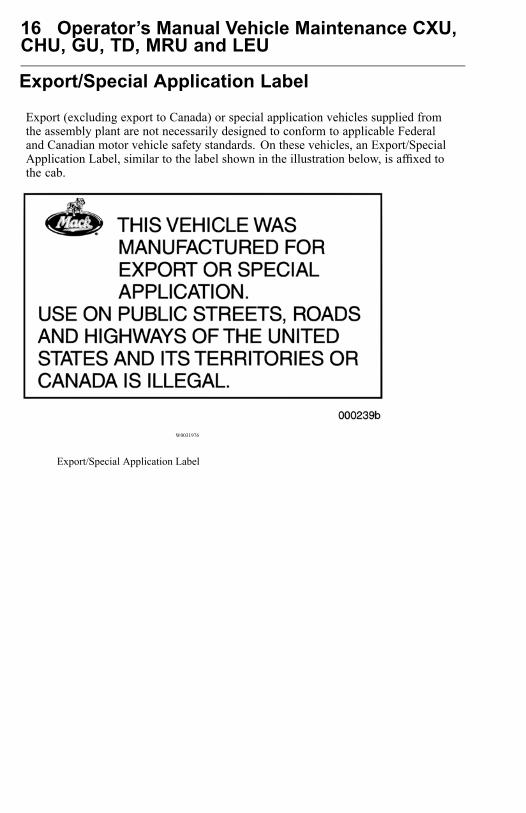
Export/Special Application Label
Export (excluding export to Canada) or special application vehicles supplied fromthe assembly plant are not necessarily designed to conform to applicable Federaland Canadian motor vehicle safety standards. On these vehicles, an Export/SpecialApplication Label, similar to the label shown in the illustration below, is affixed tothe cab.
W0031976
Export/Special Application Label
Operator’s Manual Vehicle Maintenance CXU,CHU, GU, TD, MRU and LEU 17
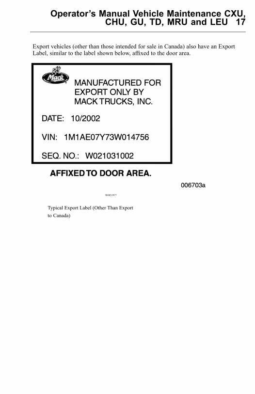
Export vehicles (other than those intended for sale in Canada) also have an ExportLabel, similar to the label shown below, affixed to the door area.
W0031977
Typical Export Label (Other Than Exportto Canada)
18 Operator’s Manual Vehicle Maintenance CXU,CHU, GU, TD, MRU and LEU
Off-Highway Identification Label
In addition to the Export/Special Application Label, vehicles designed strictly foroff-highway operations will have an Off-Highway Identification Label, similar to thelabel shown in the illustration below, affixed to the cab.
W0031978
Off-Highway Identification Label
Operator’s Manual Vehicle Maintenance CXU,CHU, GU, TD, MRU and LEU 19
Safety Information
Proper Maintenance Procedure
DANGER
Before working on a vehicle, set the parking brakes, place the transmission inneutral, and chock the wheels. Failure to do so can result in unexpected vehiclemovement and can cause serious personal injury or death.
DANGER
Exhaust gases contain carbon monoxide. Always run the engine outdoors or usea properly vented exhaust hose. Prolonged or excessive exposure may causeserious illness or death.
DANGER
Never operate the engine in an area where hydrocarbon vapors (gasoline, forexample) are present or are suspected to be present. Hydrocarbon vapors can enterthe air intake and over speed the engine, causing severe engine damage and/or anexplosion and fire. Serious personal injury or death could occur.
DANGER
Never try to operate or work on this vehicle while under the influence of alcohol.Your reflexes can be affected by even a small amount of alcohol. Drinking andoperating this vehicle can lead to an accident, causing serious personal injury ordeath.
20 Operator’s Manual Vehicle Maintenance CXU,CHU, GU, TD, MRU and LEU
WARNING
DO NOT attempt to repair or service this vehicle without having sufficient training,correct service literature and the proper tools. Failure to follow this could lead topersonal injury or making your vehicle unsafe.
WARNING
Diesel engine exhaust and some of its constituents are known to the state ofCalifornia to cause cancer, birth defects and other reproductive harm.
During Maintenance
Remove key from ignition while working on vehicle or engine.
DO NOT allow unauthorized personnel on, around or in the vehicle whenmaintenance or repair is being performed.
• When operating the engine in an enclosed area, vent the exhaust to the outside.• Before servicing your vehicle, apply the parking brakes and adequately chock the
wheels in order to prevent unintended vehicle movement. If the service procedurerequires the parking brakes to be released recheck to ensure that the wheels areadequately chocked to prevent any forward and/or rearward movement.
• DO NOT use combustible substances in or around the engine either during repairor maintenance or when running the engine.
• DO NOT wear loose clothing or jewelry that can catch or get snagged by parts ormoving components on the engine. Also wear all protective equipment required bythe job conditions, such as protective glasses, hearing protection, etc.
• Make certain that all protective covers and guards are in place and properly secured.• Never put maintenance fluids into glass containers since glass containers can break.• Report all problems in a timely manner before they threaten the safety of operating
the vehicle.• DO NOT work on the engine while it is running.• Make sure protective locks and covers are in their proper place.• DO NOT use high amperage electronic starting devices for jump-starting the
engine. Rely on conventional battery charging for charging the batteries orjump-start with the help of a start battery.

Operator’s Manual Vehicle Maintenance CXU,CHU, GU, TD, MRU and LEU 21
• DO NOT attempt repairs you do not understand. If you do not have the propertools/knowledge to perform the repairs correctly, MACK recommends contactingyour nearest MACK Truck dealer for all necessary repairs.
• When starting an engine after repairs have been made to the fuel or injectionsystem, prepare equipment for shutting off the engine intake air and/or fuel supply(to stop the engine), in case there is an over speed on start-up.
• Start the engine only from the driver seat. Never operate the starter motor acrossthe starter terminals or the batteries as this could bypass the engine neutral-startsystem as well as causing damage to the electrical or electronic systems.
Compressed Air and Water
DANGER
Compressed air can cause serious personal injury. When using compressed air forcleaning, wear a protective face shield, protective clothing and protective shoes.Pressurized water could cause particles and/or hot water to be sprayed in yourdirection and cause personal injury. The maximum air pressure must be below30 psi (200 kPa) for cleaning purposes.
Asbestos InformationNote: The MACK engine and replacement parts for it shipped from the factory areasbestos free. MACK recommends the use of only genuine MACK spare parts.Never use any parts that contain or are thought to contain asbestos. Exposure toasbestos fibers can create serious health risks, including death.
Fluid Penetration
DANGER
Always use a piece of paper or cardboard when checking for a leak. Escaping fluidunder high pressure, even a pin-hole sized leak, can penetrate body tissue, causingserious injury or death. If fluid is injected into your skin, immediate treatment mustbe administered by a doctor familiar with this type of injury.
22 Operator’s Manual Vehicle Maintenance CXU,CHU, GU, TD, MRU and LEU
Injury Prevention
Burn Prevention
Engine Parts
WARNING
Hot engine. Keep yourself clear of all hot engine parts and/or fluids. A hot engineand/or fluid can cause serious burns.
WARNING
DO NOT raise the engine hood if you see or hear steam or coolant escaping fromthe engine compartment. Wait until steam or coolant cannot be seen or heard anylonger before raising the hood.DO NOT remove the coolant fill cap if the coolant in the surge tank is boiling.Also, do not remove the cap while the engine and radiator are still hot. Scaldingfluid and steam may be blown out under pressure if the cap is taken off too soon,which can cause personal injury and damage to engine components.
W0001525
DO NOT touch any part of the engine while it is hot. Allow the engine to cool beforeany repair or maintenance is performed on the engine.
Relieve all pressure in air, oil, fuel or cooling systems before any lines, fittings orrelated items are disconnected or removed.
Operator’s Manual Vehicle Maintenance CXU,CHU, GU, TD, MRU and LEU 23
Coolant
WARNING
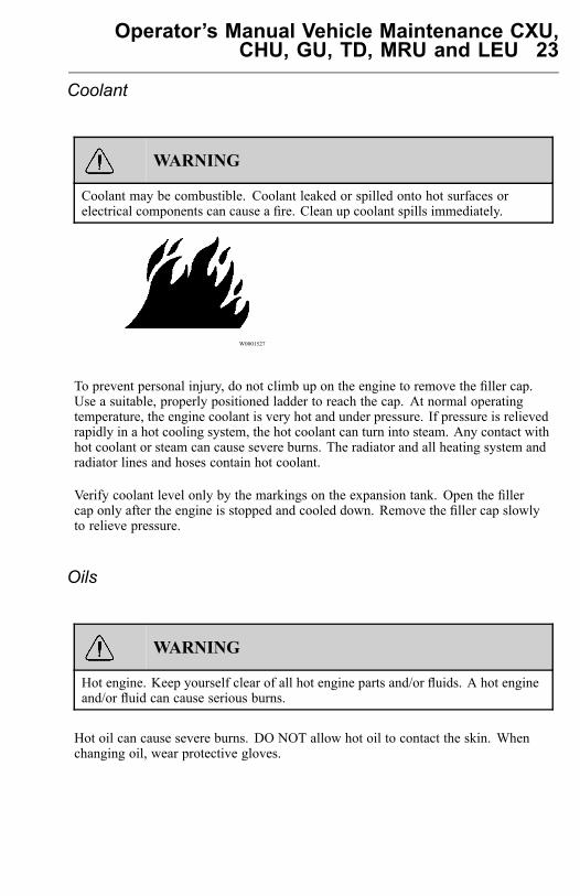
Coolant may be combustible. Coolant leaked or spilled onto hot surfaces orelectrical components can cause a fire. Clean up coolant spills immediately.
W0001527
To prevent personal injury, do not climb up on the engine to remove the filler cap.Use a suitable, properly positioned ladder to reach the cap. At normal operatingtemperature, the engine coolant is very hot and under pressure. If pressure is relievedrapidly in a hot cooling system, the hot coolant can turn into steam. Any contact withhot coolant or steam can cause severe burns. The radiator and all heating system andradiator lines and hoses contain hot coolant.
Verify coolant level only by the markings on the expansion tank. Open the fillercap only after the engine is stopped and cooled down. Remove the filler cap slowlyto relieve pressure.
Oils
WARNING
Hot engine. Keep yourself clear of all hot engine parts and/or fluids. A hot engineand/or fluid can cause serious burns.
Hot oil can cause severe burns. DO NOT allow hot oil to contact the skin. Whenchanging oil, wear protective gloves.
24 Operator’s Manual Vehicle Maintenance CXU,CHU, GU, TD, MRU and LEU
Batteries
WARNING
Always wear eye protection when working around batteries to prevent the risk ofinjury due to contact with sulfuric acid or an explosion.
WARNING
Battery posts, terminals and related accessories contain lead and lead compounds,chemicals known to the State of California to cause cancer and reproductive harm.Wash hands after handling.
Battery electrolyte contains acid and can cause injury. Avoid contact with the skinand eyes. Wash hands after touching batteries and connectors. Use of gloves isrecommended. Always wear protective glasses when working with batteries.
Speed Restrictive Tires
DANGER
Operating a vehicle equipped with speed restrictive tires in excess of their statedrating may result in tread separation and/or blowout resulting in the loss of steeringcontrol and possible collision. Serious personal injury or death could occur. Alwaysmaintain proper air pressure and never exceed the tire ratings.
When a vehicle is equipped with speed restrictive tires, DO NOT operate the vehiclein excess of the indicated speeds. If your vehicle is equipped with such tires, the speedrestrictions will be stated on the sidewall of the tires. The operator of this vehicle isurged to check the tires of the vehicle to determine if there are any limitations.
Operator’s Manual Vehicle Maintenance CXU,CHU, GU, TD, MRU and LEU 25
Fire or Explosion Prevention
DANGER
The diesel engine will operate on any fuel which enters the cylinder, whether it isfrom the injectors or from the air intake system. Therefore, if any solvent is used toflush out the air cleaner element, the engine may over speed during start-up. Enginedamage and severe injury and/or death from burns or explosion can occur.
DANGER
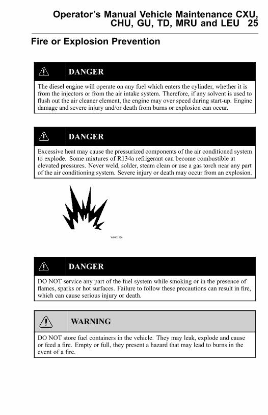
Excessive heat may cause the pressurized components of the air conditioned systemto explode. Some mixtures of R134a refrigerant can become combustible atelevated pressures. Never weld, solder, steam clean or use a gas torch near any partof the air conditioning system. Severe injury or death may occur from an explosion.
W0001526
DANGER
DO NOT service any part of the fuel system while smoking or in the presence offlames, sparks or hot surfaces. Failure to follow these precautions can result in fire,which can cause serious injury or death.
WARNING
DO NOT store fuel containers in the vehicle. They may leak, explode and causeor feed a fire. Empty or full, they present a hazard that may lead to burns in theevent of a fire.

26 Operator’s Manual Vehicle Maintenance CXU,CHU, GU, TD, MRU and LEU
W0001527
The engine should not be operated in an area where combustible gases are suspectedto be in the air. These could be drawn into the engine through the engine air intakesystem and could cause the engine to over speed with possible serious damage to theengine and bodily injury or property damage.
Make provisions for shutting off the engine intake air or fuel supply to stop the engineif there is an over speed on start-up after performing repair or maintenance on it.
Contact your nearest MACK Truck dealer for any necessary air conditioning testingor repairs.
All fuels, most lubricants and some coolant mixtures are flammable. Diesel fuelis flammable. Gasoline is flammable. The mixture of diesel and gasoline fumes isextremely explosive. DO NOT smoke while refueling or when in a refueling area.
Keep all fuels and lubricants stored in properly marked containers and away from allunauthorized personnel. Store oily rags or other flammable material in a protectivecontainer, in a safe place.
Remove all flammable material such as fuel, oil and other substances before theyaccumulate on the engine.
DO NOT expose the engine to flames, driving over burning ground.
DO NOT weld or flame cut on or around pipes or tubes that contain flammable fluids.
Exhaust heat shields may be installed to protect oil or fuel carrying lines and pipesfrom hot exhaust parts. To protect from pipe or seal failure, install heat shieldscorrectly.
Provide adequate and proper waste oil disposal. Always dispose of waste liquidsaccording to Federal and local regulations. Oil and fuel filters should be properlyinstalled and housing covers tightened to the proper torque when being changed.
Operator’s Manual Vehicle Maintenance CXU,CHU, GU, TD, MRU and LEU 27
Starting Aids
DANGER
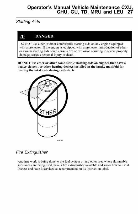
DO NOT use ether or other combustible starting aids on any engine equippedwith a preheater. If the engine is equipped with a preheater, introduction of etheror similar starting aids could cause a fire or explosion resulting in severe propertydamage, serious personal injury or death.
DO NOT use ether or other combustible starting aids on engines that have aheater element or other heating devices installed in the intake manifold forheating the intake air during cold-starts.
W0001484
Fire Extinguisher
Anytime work is being done to the fuel system or any other area where flammablesubstances are being used, have a fire extinguisher available and know how to use it.Inspect and have it serviced as recommended on its instruction label.
28 Operator’s Manual Vehicle Maintenance CXU,CHU, GU, TD, MRU and LEU
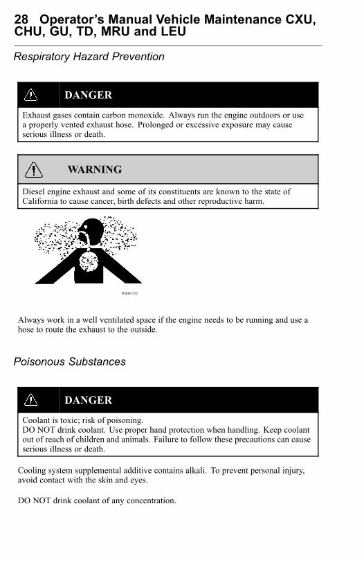
Respiratory Hazard Prevention
DANGER
Exhaust gases contain carbon monoxide. Always run the engine outdoors or usea properly vented exhaust hose. Prolonged or excessive exposure may causeserious illness or death.
WARNING
Diesel engine exhaust and some of its constituents are known to the state ofCalifornia to cause cancer, birth defects and other reproductive harm.
W0001523
Always work in a well ventilated space if the engine needs to be running and use ahose to route the exhaust to the outside.
Poisonous Substances
DANGER
Coolant is toxic; risk of poisoning.DO NOT drink coolant. Use proper hand protection when handling. Keep coolantout of reach of children and animals. Failure to follow these precautions can causeserious illness or death.
Cooling system supplemental additive contains alkali. To prevent personal injury,avoid contact with the skin and eyes.
DO NOT drink coolant of any concentration.
Operator’s Manual Vehicle Maintenance CXU,CHU, GU, TD, MRU and LEU 29
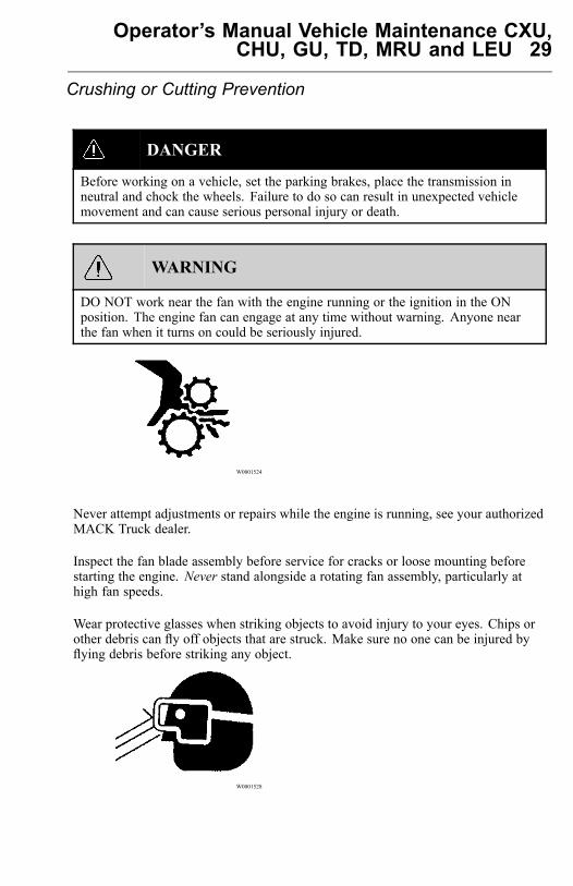
Crushing or Cutting Prevention
DANGER
Before working on a vehicle, set the parking brakes, place the transmission inneutral and chock the wheels. Failure to do so can result in unexpected vehiclemovement and can cause serious personal injury or death.
WARNING
DO NOT work near the fan with the engine running or the ignition in the ONposition. The engine fan can engage at any time without warning. Anyone nearthe fan when it turns on could be seriously injured.
W0001524
Never attempt adjustments or repairs while the engine is running, see your authorizedMACK Truck dealer.
Inspect the fan blade assembly before service for cracks or loose mounting beforestarting the engine. Never stand alongside a rotating fan assembly, particularly athigh fan speeds.
Wear protective glasses when striking objects to avoid injury to your eyes. Chips orother debris can fly off objects that are struck. Make sure no one can be injured byflying debris before striking any object.
W0001528

30 Operator’s Manual Vehicle Maintenance CXU,CHU, GU, TD, MRU and LEU
Climbing Up and Down
DANGER
Always have three limbs (one foot and two hands or two feet and one hand) incontact with the vehicle at all times when entering or exiting the cab or the areabehind the cab. Failure to follow this warning can result in serious personal injuryor death.
DO NOT climb up on or jump off from the engine or stand on components that cannotsupport your weight. Use an adequate ladder or scaffolding, suitably situated.
DO NOT use top of engine or cowling ledge as foothold when reaching on top of cab.Clean steps, handholds and areas of the vehicle on which you will be working or arearound. Refer to the Operators Manual for proper entry and exit procedures.
Always use a three-point stance (two hands and one foot or one hand and twofeet) whenever climbing up or down.
Engine Damage Prevention
Before Starting the Engine
DANGER
Before working on a vehicle, set the parking brakes, place the transmission inneutral and chock the wheels. Failure to do so can result in unexpected vehiclemovement and can cause serious personal injury or death.
Inspect engine for potential hazards. Make sure all protective guards and covers areproperly installed if an engine needs to be started to make adjustments or checks. Tohelp prevent an accident by moving parts, work carefully around them.
DO NOT disable or bypass automatic alarm/shutoff circuits. They are provided toprevent personal injury and engine damage.
Only properly trained and authorized MACK Service Technicians may attempt repairson this vehicle.
Operator’s Manual Vehicle Maintenance CXU,CHU, GU, TD, MRU and LEU 31
Engine Starting
DO NOT start the engine or move any of the controls or disengage the parking brakeif the warning tag DO NOT OPERATE is attached to the ignition key or located onthe dash. Check with the person who attached the tag before starting.
Make sure no one is working on or close to the engine or components driven by theengine before starting it. Always make an inspection of the engine before and afterstarting.
Diesel engine exhaust contains products of combustion which may be harmful to yourhealth. Always start and operate the engine in a well-ventilated area, and if in anenclosed area, vent the exhaust to the outside.
Start the engine only from the driver seat in the cab. Never start the engine byshorting across the starter motor terminals or batteries to start the engine as this couldbypass the engine neutral-start system as well as damage the electrical and electronicsystem. Always start the engine according to the required engine starting proceduredescribed in this operators manual to prevent major engine component damage andpersonal injury.
32 Operator’s Manual Vehicle Maintenance CXU,CHU, GU, TD, MRU and LEU
Electric System Damage Prevention
Electric and Electronic Systems
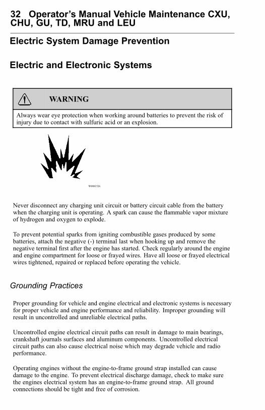
WARNING
Always wear eye protection when working around batteries to prevent the risk ofinjury due to contact with sulfuric acid or an explosion.
W0001526
Never disconnect any charging unit circuit or battery circuit cable from the batterywhen the charging unit is operating. A spark can cause the flammable vapor mixtureof hydrogen and oxygen to explode.
To prevent potential sparks from igniting combustible gases produced by somebatteries, attach the negative (-) terminal last when hooking up and remove thenegative terminal first after the engine has started. Check regularly around the engineand engine compartment for loose or frayed wires. Have all loose or frayed electricalwires tightened, repaired or replaced before operating the vehicle.
Grounding Practices
Proper grounding for vehicle and engine electrical and electronic systems is necessaryfor proper vehicle and engine performance and reliability. Improper grounding willresult in uncontrolled and unreliable electrical paths.
Uncontrolled engine electrical circuit paths can result in damage to main bearings,crankshaft journals surfaces and aluminum components. Uncontrolled electricalcircuit paths can also cause electrical noise which may degrade vehicle and radioperformance.
Operating engines without the engine-to-frame ground strap installed can causedamage to the engine. To prevent electrical discharge damage, check to make surethe engines electrical system has an engine-to-frame ground strap. All groundconnections should be tight and free of corrosion.
Operator’s Manual Vehicle Maintenance CXU,CHU, GU, TD, MRU and LEU 33
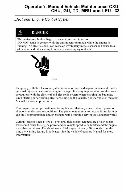
Electronic Engine Control System
DANGER
The engine uses high voltage to the electronic unit injectors.DO NOT come in contact with the unit injector terminals while the engine isrunning. An electric shock can cause an involuntary muscle spasm and cause lossof balance and falls leading to severe personal injury or death.
W0001522
Tampering with the electronic system installation can be dangerous and could result inpersonal injury or death and/or engine damage. It is very important to take the properprecautions with the electrical and electronic system when charging the batteries,jump-starting or performing electric welding on the vehicle. See the vehicle OperatorsManual for correct procedures.
This engine is equipped with monitoring features that may cause reduced power orshutdown under certain conditions. The power output, monitoring and idling featurescan only be programmed and/or changed with electronic service tools and passwords.
Certain features, such as low oil pressure, high coolant temperature or low coolantlevel could cause the engine power and/or vehicle speed to be limited and the enginemay also shut down. The shutdown will take approximately 30 seconds from thetime the warning feature is activated. See the vehicle Operators Manual for moreinformation.
34 Operator’s Manual Vehicle Maintenance CXU,CHU, GU, TD, MRU and LEU
Reporting Safety Defects
USA
The National Highway Traffic Safety Administration (NHTSA) and MACK Inc.should be informed immediately if you believe that the vehicle has a defect that couldcause a vehicle accident, injury or death.
Contact NHTSA by calling the Auto Safety Hotline at 1 (888) 327-4236, by writing toNHTSA, U.S. Department of Transportation, Washington, DC 20590, by TTY at 1(800) 424-9153, or visit their website at www.nhtsa.dot.gov.
Canada
Refer customer complaints to MACK Trucks Canada, Inc. or to Transport Canada,Defect Investigations and Recalls.
Canadian customers who wish to report a safety-related defect to Transport Canada,Defect Investigations and Recalls, may telephone the toll free hotline 1 (800)333-0510 (within Canada only) or call 1 (613) 993-9851 (from Ottawa region oroutside Canada). Contact Transport Canada by mail at: Transport Canada, ASFAD,Place de Ville Tower C, 330 Sparks Street, Ottawa ON K1A 0N5.
For additional road safety information, please visit the Road Safety website at:http://www.tc.gc.ca/roadsafety/menu.htm
Mexico
MACK Trucks de Mexico, S.A. de C.V. should be informed immediately if youbelieve the vehicle has a defect that could cause a vehicle accident, injury or death.Contact MACK Trucks de Mexico by calling: 01 (800) 90 94 900 (within Mexicoonly) or 011-52-55-50-81-68-50, or by writing to: MACK Trucks de Mexico, S.A.de C.V., Prol. Paseo de la Reforma 600, 1er. Piso 121, Col. Santa Fe Pea Blanca,C.P. 01210, Mexico, D.F.
Note: For Roadside assistance information see “CUSTOMER SERVICE”, page 158.
Operator’s Manual Vehicle Maintenance CXU,CHU, GU, TD, MRU and LEU 35
General Engine Information
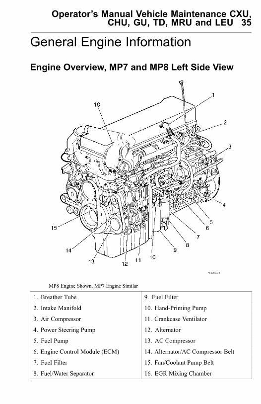
Engine Overview, MP7 and MP8 Left Side View
W2006034
MP8 Engine Shown, MP7 Engine Similar
1. Breather Tube 9. Fuel Filter
2. Intake Manifold 10. Hand-Priming Pump
3. Air Compressor 11. Crankcase Ventilator
4. Power Steering Pump 12. Alternator
5. Fuel Pump 13. AC Compressor
6. Engine Control Module (ECM) 14. Alternator/AC Compressor Belt
7. Fuel Filter 15. Fan/Coolant Pump Belt
8. Fuel/Water Separator 16. EGR Mixing Chamber
36 Operator’s Manual Vehicle Maintenance CXU,CHU, GU, TD, MRU and LEU
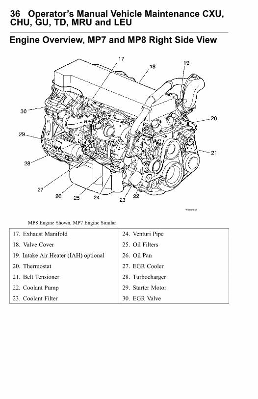
Engine Overview, MP7 and MP8 Right Side View
W2006035
MP8 Engine Shown, MP7 Engine Similar
17. Exhaust Manifold 24. Venturi Pipe
18. Valve Cover 25. Oil Filters
19. Intake Air Heater (IAH) optional 26. Oil Pan
20. Thermostat 27. EGR Cooler
21. Belt Tensioner 28. Turbocharger
22. Coolant Pump 29. Starter Motor
23. Coolant Filter 30. EGR Valve
Operator’s Manual Vehicle Maintenance CXU,CHU, GU, TD, MRU and LEU 37
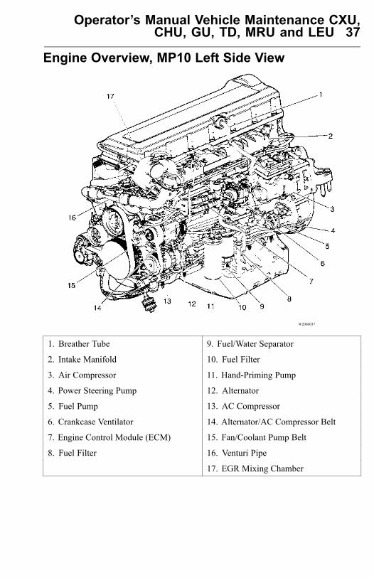
Engine Overview, MP10 Left Side View
W2006037
1. Breather Tube 9. Fuel/Water Separator
2. Intake Manifold 10. Fuel Filter
3. Air Compressor 11. Hand-Priming Pump
4. Power Steering Pump 12. Alternator
5. Fuel Pump 13. AC Compressor
6. Crankcase Ventilator 14. Alternator/AC Compressor Belt
7. Engine Control Module (ECM) 15. Fan/Coolant Pump Belt
8. Fuel Filter 16. Venturi Pipe
17. EGR Mixing Chamber
38 Operator’s Manual Vehicle Maintenance CXU,CHU, GU, TD, MRU and LEU
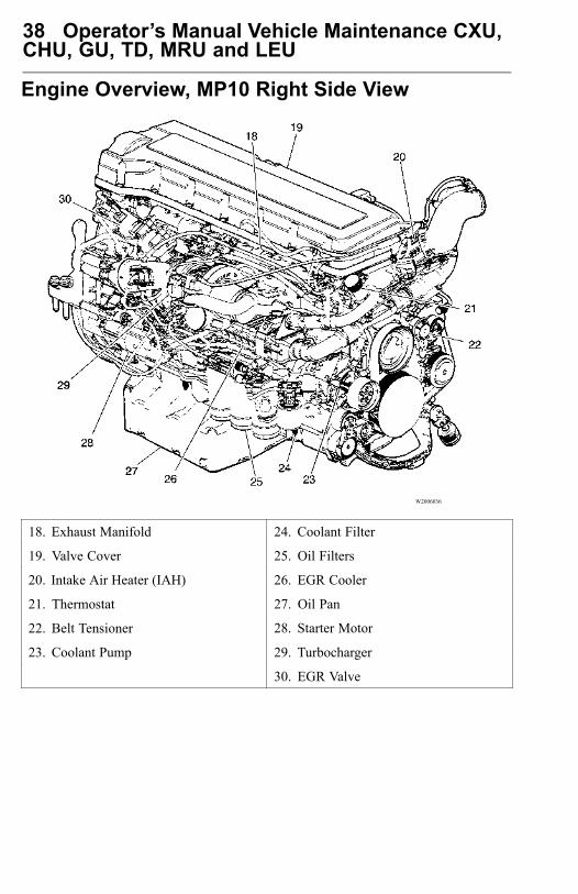
Engine Overview, MP10 Right Side View
W2006036
18. Exhaust Manifold 24. Coolant Filter
19. Valve Cover 25. Oil Filters
20. Intake Air Heater (IAH) 26. EGR Cooler
21. Thermostat 27. Oil Pan
22. Belt Tensioner 28. Starter Motor
23. Coolant Pump 29. Turbocharger
30. EGR Valve
Operator’s Manual Vehicle Maintenance CXU,CHU, GU, TD, MRU and LEU 39
Electrical System
Batteries
WARNING
Battery posts, terminals and relatedaccessories contain lead and leadcompounds, chemicals known to theState of California to cause cancer andreproductive harm. Wash hands afterhandling.
WARNING
Always wear eye protection whenworking around batteries to preventthe risk of injury due to contact withsulfuric acid or an explosion.
CAUTION
Disconnecting battery cables whenvehicle is equipped with power doorlocks will result in automatic lockingof doors.
CAUTION
When using a pressure washer to cleanthe vehicle, do not direct the spray atelectrical components in the enginecompartment such as the alternator,starter and compressors. Water sprayfrom pressure washers can damageelectrical components.
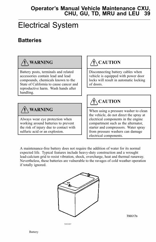
A maintenance-free battery does not require the addition of water for its normalexpected life. Typical features include heavy-duty construction and a wroughtlead-calcium grid to resist vibration, shock, overcharge, heat and thermal runaway.Nevertheless, these batteries are vulnerable to the ravages of cold weather operationif totally ignored.
W0054087
Battery
40 Operator’s Manual Vehicle Maintenance CXU,CHU, GU, TD, MRU and LEU
Be sure that the batteries used in a particular vehicle are rated for the specifiedCold Cranking Amperes (CCAs) necessary to ensure reliable cold weather starts.This is important, since even well-maintained batteries chilled to 18 °C (0 °F) maytemporarily be capable of providing only 40% of their rated capacity at 27 °C (80 °F).
Keep the terminals clean to prevent formation of power-robbing corrosion.
In winter, to avoid freezing the electrolyte, the battery must be fully charged. A fullydischarged battery will freeze solid at 5 °C (23 °F) and possibly sustain permanentdamage.
Before the onset of cold weather, be sure to protect this vital component by monitoringits condition as well as inspecting the charging and starting systems.
Operator’s Manual Vehicle Maintenance CXU,CHU, GU, TD, MRU and LEU 41
Battery Warmer
A battery warmer can be added to raise the temperature of the battery core andfacilitate quick starting in cold weather.
Battery Condition
The first procedure when testing a battery is to check for external damage suchas a cracked case, loose or corroded terminals, or signs of excessive gassing orovercharging.
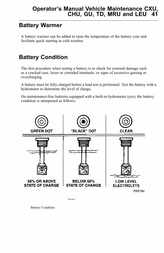
A battery must be fully charged before a load test is performed. Test the battery with ahydrometer to determine the level of charge.
On maintenance-free batteries equipped with a built-in hydrometer (eye), the batterycondition is interpreted as follows:
W0054088
Battery Condition
42 Operator’s Manual Vehicle Maintenance CXU,CHU, GU, TD, MRU and LEU
• Green dot visible Any green appearance should be interpreted as a green dot andmeans that the battery is at or above a 65% state of charge and is ready for use ortesting. This does not automatically mean that the battery is in good condition.
• Dark green dot not visible (black dot) This indicates that the battery is below a65% state of charge and must be charged before testing. A black dot does not meanthat the battery is automatically bad.
• Clear or light yellow This means that the electrolyte level is below the level ofthe built-in hydrometer, which may have been caused by tipping of the battery, acracked case, or overcharging. This battery should be replaced.
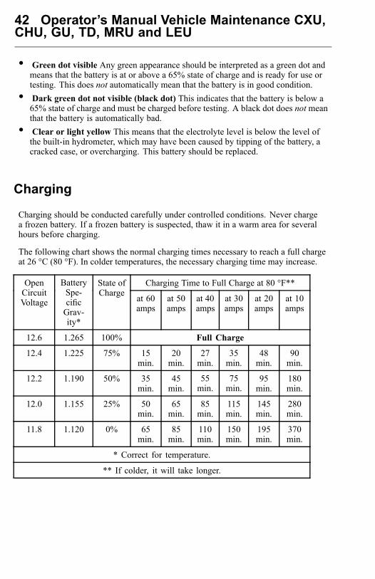
Charging
Charging should be conducted carefully under controlled conditions. Never chargea frozen battery. If a frozen battery is suspected, thaw it in a warm area for severalhours before charging.
The following chart shows the normal charging times necessary to reach a full chargeat 26 °C (80 °F). In colder temperatures, the necessary charging time may increase.
Charging Time to Full Charge at 80 °F**OpenCircuitVoltage
BatterySpe-cificGrav-ity*
State ofCharge at 60
ampsat 50amps
at 40amps
at 30amps
at 20amps
at 10amps
12.6 1.265 100% Full Charge
12.4 1.225 75% 15min.
20min.
27min.
35min.
48min.
90min.
12.2 1.190 50% 35min.
45min.
55min.
75min.
95min.
180min.
12.0 1.155 25% 50min.
65min.
85min.
115min.
145min.
280min.
11.8 1.120 0% 65min.
85min.
110min.
150min.
195min.
370min.
* Correct for temperature.
** If colder, it will take longer.
Operator’s Manual Vehicle Maintenance CXU,CHU, GU, TD, MRU and LEU 43
Completely Discharged BatteriesExtremely cold or completely discharged batteries may not initially show a chargesince the electrolyte is nearly pure water and, therefore, a poor conductor. As theacid level in the electrolyte increases during charging, the charging current will alsoincrease. Use the following procedure when charging a completely discharged battery:1 Measure the voltage at the battery terminals. If it is below 10 volts, current will be
very low and may not show up on many battery charger ammeters.2 Set the charger on the high setting.3 Some chargers have a polarity protection feature which prevents accidental reversal
of the charger leads. A completely discharged battery will not have enough voltageto override this feature, making it appear that the battery will not accept a charge.Check the charger manufacturers instructions on how to bypass this feature.
4 Once the battery starts to accept a charge, the charging rate will rise very rapidly.Carefully monitor the ammeter to prevent too-high a charging rate.
5 Proceed to charge battery at one-tenth of its rated capacity for one-half hour.Example: For battery rated at 64 (amps-hour), charge at 6.4 amp setting.
Note: Batteries with very low voltage (below 11.6 volts) or those that do notinitially accept a charge are not necessarily defective. Batteries that have beendischarged for long periods of time may be heavily sulfated or hydrated (containinglead shorts that cause the battery to self-discharge). To accept a charge, batterieswith either of these conditions may require a longer charging time or a very highinitial charge.
Use the following chart to determine the time required for the battery to beginaccepting a measurable charge. (If the battery has not started to accept a charge afterthe specified time, it should be replaced.)
Charger Voltage Hours
16.0 or more Up to 4
14.0 to 15.9 Up to 8
13.9 or less Up to 16
44 Operator’s Manual Vehicle Maintenance CXU,CHU, GU, TD, MRU and LEU
Load Test
A battery must be fully charged before performing a load test. To load-test a batterythat is fully charged, proceed as follows:1 Connect a load tester and voltmeter across the battery terminals.2 Apply a load so that a figure of 300 amps is obtained for 15 seconds to remove the
battery surface charge.3 Wait 60 seconds to let the battery recover and then apply the proper test load
to the battery to determine its condition. To get the proper load, use half thecranking performance rating. Read the voltage after 15 seconds. Remember thatthe minimum voltage varies according to temperature. Consult the following chartfor the proper specification. If the battery voltage does not fall below the minimumtest voltage after 15 seconds, the battery is acceptable for use.
Load Test Temperature Correction
TemperatureMinimum Voltage
C F
9.6 21 70
9.5 16 60
9.4 10 50
9.3 4 40
9.1 1 30
8.9 7 20
8.7 12 10
8.5 18 0
Electrical Connection Protection
If corrosion is seen at any external ring-type terminal connections, such as those usedat the starter, alternator, chassis and/or engine grounds, etc., LPS HardCoat CorrosionProtectant must be applied to the connection after disconnecting, cleaning andreconnecting the ring terminal. Additionally, LPS HardCoat should be applied to anyring-type terminal connector following any type of service procedure which involveddisconnecting/reconnecting the ring terminals (such as component replacement,troubleshooting, service and repair, etc.).
Operator’s Manual Vehicle Maintenance CXU,CHU, GU, TD, MRU and LEU 45
Wiring Harness/Cable and Connector Protection
To help protect your vehicle’s external high amperage electrical cables andconnections from corrosion due to the effects of newer salts (calcium chloride andmagnesium chloride) on the roadways, MACK is offering a corrosion inhibitor part20916273 for purchase through the PDC.MACK recommends coating all high amperage (positive and ground) exposedelectrical connections at a minimum of every 6 months or, whenever the connectorhas been disassembled. The following list contains the recommended connections thatshould be liberally coated with the corrosion inhibitor;• Battery connections• Battery main shut off switch connections• Maxi and/or Mega fuse connections• All ground stud connections• Electrical pneumatic pass-thru connections• All alternator connections• All starter connections• Intake preheater and preheater relay connections• Electrical power inverter connections
All connections should be cleaned and free of previously applied inhibitors, oil, dirt,dust or other contaminants prior to application. Allow time for the product to drybefore use (drying time may vary depending temperature, humidity, etc.).
For more information regarding this corrosion inhibitor produced by LPS Worldwide,visit their web site at www.lpslabs.com.
46 Operator’s Manual Vehicle Maintenance CXU,CHU, GU, TD, MRU and LEU
Lighting
WARNING
Using incorrect bulbs or lamps may result in failures that could lead to a fire or avehicle accident caused by improper lighting.
Check all lights on the vehicle daily for proper function. Replace burned out insertsand bulbs. Replace any broken or cracked side or rear reflectors. Headlights should bechecked for aim at least once per year.
Operator’s Manual Vehicle Maintenance CXU,CHU, GU, TD, MRU and LEU 47
Precautions When Installing Electrical Equipment
Connecting electrically powered or electrically controlled equipment to a vehiclemay cause interference with other vehicle electrical or electronic equipment (such asABS systems, Rollover Stability Systems, etc.). The amount of interference dependsupon the operating frequency of any new signals and the degree to which transientsignals are coupled to the vehicle system.
Note: Whenever new electrical equipment is installed, it is the obligation of theinstaller to ensure that the new equipment does not interfere with the proper operationof all other electrical systems on the vehicle.
If new electrical equipment is installed, a vehicle checkout procedure should beperformed.1 Perform the checkout procedure under the following conditions:• Engine running• Brake system air pressure in operating range• Vehicle stationary• Brake pedal fully depressed
2 Operate the new equipment under all starting, running and sutdown conditions.3 Listen for signs of air exhausting from the ABS modulator valves (which is an
indication of an interference condition).4 Correct all interference conditions before operating the vehicle.
Note: The center pin of the standard seven-pin trailer electrical connector has beenstandardized as the dedicated connection for uninterrupted power for trailer ABS. Thispin is always hot when the tractor ignition is turned on.
DANGER
Some trailers manufactured prior tothe trailer ABS regulations may usethe center pin to power certain trailerauxiliary equipment. The possibilityexists that this auxiliary equipment maybe unexpectedly activated by the truckor tractor electrical system, resulting inpersonal injury or damage to equipment.Caution must be used when connectingthe trailer electrical connector to ensurethat power to the center pin will notunintentionally activate any trailerauxiliary equipment.
48 Operator’s Manual Vehicle Maintenance CXU,CHU, GU, TD, MRU and LEU
MACK Road Stability AdvantageThe MACK Road Stability Advantage (RSA) is an available option on certainMACK highway tractors and straight trucks. The RSA system, which is based on theBendix ABS-6 Advanced with ESP (Electronic Stability Program) System, aids theoperator in maintaining control of the vehicle during jackknife or rollover events byapplying select brakes and reducing engine power as required by the specific situation.This system is integral with the anti-lock brake system and uses the standard ABScomponents (such as wheel speed sensors and modulator valves). Additionally, asteering angle sensor and a yaw rate/lateral acceleration sensor package providesinformation concerning vehicle movement to the electronic control unit.
Before delivery to the end user, a parameter set tuned for the specific vehicle and theVIN for the chassis are loaded into the ABS electronic control unit. This ensuresoptimal performance of the MACK RSA system for the specific vehicle.
Alterations and modifications to an RSA-equipped vehicle, such as wheel basechanges (either lengthening or shortening), the addition of an auxiliary lift axle or theremoval of a factory-installed lift axle, or major body changes, such as conversion of atractor to a truck or an axle, suspension or steering system component modification,are NOT allowed, as these changes will adversely affect performance of the roadstability system. Should such changes be unavoidable, the system must be disabled byhaving a qualified technician replace the Bendix Advanced EC-60 (ABS control unitwith ESP) with a Bendix Premium EC-60 ECU (ABS control unit without ESP).
DANGER
Failure to disable the RSA system on avehicle that has been modified or alteredwill result in serious vehicle brakingand performance issues, includingunnecessary system interventions.These interventions could lead to a lossof vehicle control.In addition to disabling the system, anycab labels, such as warning and cautionlabels relating to the Bendix ABS-6Advanced with ESP system located onthe sun visor must be removed, andnotations must be made in the operatorsmanuals so that the vehicle operator hasa clear understanding as to which ABSoptions are installed on the vehicle.
Operator’s Manual Vehicle Maintenance CXU,CHU, GU, TD, MRU and LEU 49
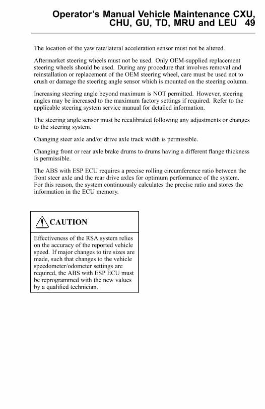
The location of the yaw rate/lateral acceleration sensor must not be altered.
Aftermarket steering wheels must not be used. Only OEM-supplied replacementsteering wheels should be used. During any procedure that involves removal andreinstallation or replacement of the OEM steering wheel, care must be used not tocrush or damage the steering angle sensor which is mounted on the steering column.
Increasing steering angle beyond maximum is NOT permitted. However, steeringangles may be increased to the maximum factory settings if required. Refer to theapplicable steering system service manual for detailed information.
The steering angle sensor must be recalibrated following any adjustments or changesto the steering system.
Changing steer axle and/or drive axle track width is permissible.
Changing front or rear axle brake drums to drums having a different flange thicknessis permissible.
The ABS with ESP ECU requires a precise rolling circumference ratio between thefront steer axle and the rear drive axles for optimum performance of the system.For this reason, the system continuously calculates the precise ratio and stores theinformation in the ECU memory.
CAUTION
Effectiveness of the RSA system relieson the accuracy of the reported vehiclespeed. If major changes to tire sizes aremade, such that changes to the vehiclespeedometer/odometer settings arerequired, the ABS with ESP ECU mustbe reprogrammed with the new valuesby a qualified technician.
50 Operator’s Manual Vehicle Maintenance CXU,CHU, GU, TD, MRU and LEU
Engine Storage
Engine Storage
If the vehicle must be parked for a period (more than 30 days), protect it as follows:
1 Drain the engine oil.2 Fill up to the proper level with oil of the recommended quality and viscosity.3 Fill up the fuel tanks with the recommended grade of fuel.4 Run the engine for two minutes around 1000 rpm. Shut the engine down. DO
NOT drain the oil after this run.5 Check the coolant for proper levels of antifreeze and inhibitor (SCA) protection.
Service as necessary.6 Seal all engine openings using protective covers.
To return to service an engine preserved in this manner, remove previously installedprotective covers. Check all fluid levels and if necessary replace engine oilcontaminated by condensation.
Operator’s Manual Vehicle Maintenance CXU,CHU, GU, TD, MRU and LEU 51
Maintenance and Service
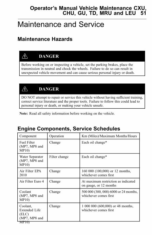
Maintenance Hazards
DANGER
Before working on or inspecting a vehicle, set the parking brakes, place thetransmission in neutral and chock the wheels. Failure to do so can result inunexpected vehicle movement and can cause serious personal injury or death.
DANGER
DO NOT attempt to repair or service this vehicle without having sufficient training,correct service literature and the proper tools. Failure to follow this could lead topersonal injury or death, or making your vehicle unsafe.
Note: Read all safety information before working on the vehicle.
Engine Components, Service SchedulesComponent Operation Km (Miles)/Maximum Months/Hours
Fuel Filter(MP7, MP8 andMP10)
Change Each oil change*
Water Separator(MP7, MP8 andMP10)
Filter change Each oil change*
Air Filter EPA2010
Change 160 000 (100,000) or 12 months,whichever comes first
Air Filter Euro 4 Change At maximum restriction as indicatedon gauge, or 12 months
Coolant(MP7, MP8 andMP10)
Change 500 000 (300, 000) 6000 or 24 months,whichever comes first
Coolant,Extended Life(ELC)(MP7, MP8 andMP10)
Change 1 000 000 (600,000) or 48 months,whichever comes first
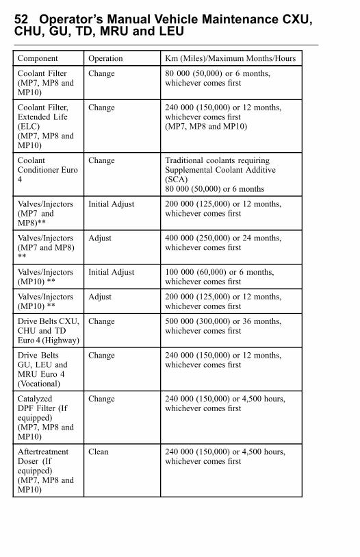
52 Operator’s Manual Vehicle Maintenance CXU,CHU, GU, TD, MRU and LEU
Component Operation Km (Miles)/Maximum Months/Hours
Coolant Filter(MP7, MP8 andMP10)
Change 80 000 (50,000) or 6 months,whichever comes first
Coolant Filter,Extended Life(ELC)(MP7, MP8 andMP10)
Change 240 000 (150,000) or 12 months,whichever comes first(MP7, MP8 and MP10)
CoolantConditioner Euro4
Change Traditional coolants requiringSupplemental Coolant Additive(SCA)80 000 (50,000) or 6 months
Valves/Injectors(MP7 andMP8)**
Initial Adjust 200 000 (125,000) or 12 months,whichever comes first
Valves/Injectors(MP7 and MP8)**
Adjust 400 000 (250,000) or 24 months,whichever comes first
Valves/Injectors(MP10) **
Initial Adjust 100 000 (60,000) or 6 months,whichever comes first
Valves/Injectors(MP10) **
Adjust 200 000 (125,000) or 12 months,whichever comes first
Drive Belts CXU,CHU and TDEuro 4 (Highway)
Change 500 000 (300,000) or 36 months,whichever comes first
Drive BeltsGU, LEU andMRU Euro 4(Vocational)
Change 240 000 (150,000) or 12 months,whichever comes first
CatalyzedDPF Filter (Ifequipped)(MP7, MP8 andMP10)
Change 240 000 (150,000) or 4,500 hours,whichever comes first
AftertreatmentDoser (Ifequipped)(MP7, MP8 andMP10)
Clean 240 000 (150,000) or 4,500 hours,whichever comes first
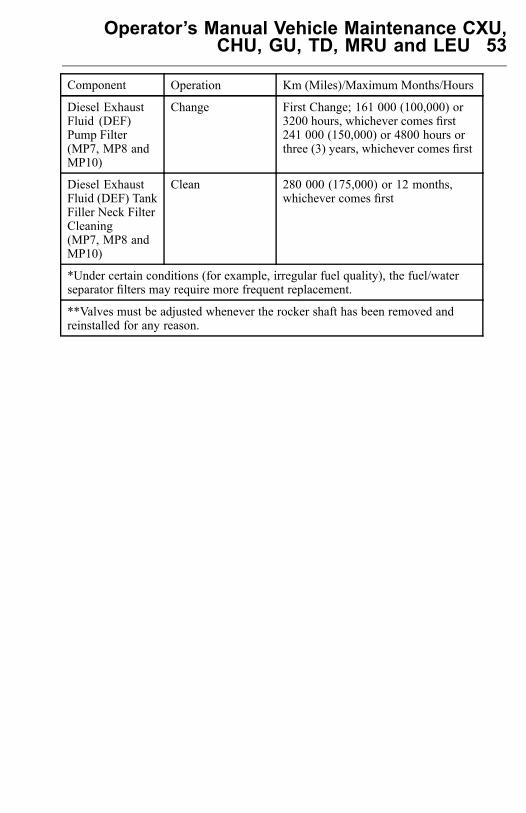
Operator’s Manual Vehicle Maintenance CXU,CHU, GU, TD, MRU and LEU 53
Component Operation Km (Miles)/Maximum Months/Hours
Diesel ExhaustFluid (DEF)Pump Filter(MP7, MP8 andMP10)
Change First Change; 161 000 (100,000) or3200 hours, whichever comes first241 000 (150,000) or 4800 hours orthree (3) years, whichever comes first
Diesel ExhaustFluid (DEF) TankFiller Neck FilterCleaning(MP7, MP8 andMP10)
Clean 280 000 (175,000) or 12 months,whichever comes first
*Under certain conditions (for example, irregular fuel quality), the fuel/waterseparator filters may require more frequent replacement.
**Valves must be adjusted whenever the rocker shaft has been removed andreinstalled for any reason.

54 Operator’s Manual Vehicle Maintenance CXU,CHU, GU, TD, MRU and LEU
Cooling System
General Coolant Information
DANGER
Coolant is toxic; risk of poisoning. DO NOT drink coolant. Use proper handprotection when handling. Keep coolant out of reach of children and animals.Failure to follow these precautions can cause serious illness or death.
WARNING
DO NOT raise the engine hood if you see or hear steam or coolant escaping fromthe engine compartment. Wait until steam or coolant cannot be seen or heard beforeraising the hood.DO NOT remove the coolant fill cap if the coolant in the surge tank is boiling.Also, DO NOT remove the cap while the engine and radiator are still hot. Scaldingfluid and steam may be blown out under pressure if the cap is taken off too soonand can cause personal injury.
WARNING
Coolant may be combustible. Coolant leaked or spilled onto hot surfaces orelectrical components can cause a fire. Clean up coolant spills immediately.
CAUTION
MACK Inc. does not recommend using plain water in the cooling system. Wateralone is corrosive at engine operating temperatures and does not provide adequateboiling protection. The engine may develop corrosion and cavitation problems inthe engine and radiator, and the boiling point of the coolant is lowered comparedto a proper antifreeze and water mixture. Failure to follow MACK Inc. coolingsystem care/maintenance recommendations can render the warranty invalid.
Operator’s Manual Vehicle Maintenance CXU,CHU, GU, TD, MRU and LEU 55
The cooling system plays an important role in overall engine performance by keepingthe engine within the normal operating temperature range hot enough for efficientcombustion, and cool enough to prevent engine damage caused by overheating.Good preventive maintenance practices, along with monitoring cooling systemperformance, go a long way in preventing engine damage that could result fromcooling system problems. The maintenance items and tests outlined in this sectionshould be performed at the intervals specified to ensure optimum performance fromthe cooling system.
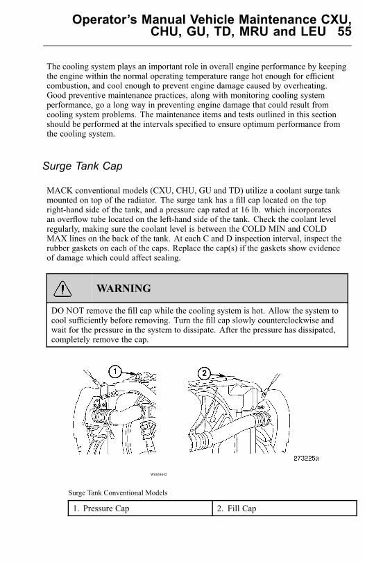
Surge Tank Cap
MACK conventional models (CXU, CHU, GU and TD) utilize a coolant surge tankmounted on top of the radiator. The surge tank has a fill cap located on the topright-hand side of the tank, and a pressure cap rated at 16 lb. which incorporatesan overflow tube located on the left-hand side of the tank. Check the coolant levelregularly, making sure the coolant level is between the COLD MIN and COLDMAX lines on the back of the tank. At each C and D inspection interval, inspect therubber gaskets on each of the caps. Replace the cap(s) if the gaskets show evidenceof damage which could affect sealing.
WARNING
DO NOT remove the fill cap while the cooling system is hot. Allow the system tocool sufficiently before removing. Turn the fill cap slowly counterclockwise andwait for the pressure in the system to dissipate. After the pressure has dissipated,completely remove the cap.
W0054042
Surge Tank Conventional Models
1. Pressure Cap 2. Fill Cap
56 Operator’s Manual Vehicle Maintenance CXU,CHU, GU, TD, MRU and LEU
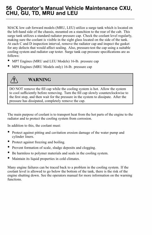
MACK low cab forward models (MRU, LEU) utilize a surge tank which is located onthe left-hand side of the chassis, mounted on a stanchion to the rear of the cab. Thissurge tank utilizes a standard radiator pressure cap. Check the coolant level regularly,making sure the coolant is visible in the sight glass located on the side of the tank.At each C and D inspection interval, remove the radiator cap and inspect the gasketfor any defects that would affect sealing. Also, pressure-test the cap using a suitablecooling system and radiator cap tester. Surge tank cap pressure specifications are asfollows:• MP7 Engines (MRU and LEU Models) 16-lb. pressure cap• MP8 Engines (MRU Models only) 16-lb. pressure cap
WARNING
DO NOT remove the fill cap while the cooling system is hot. Allow the systemto cool sufficiently before removing. Turn the fill cap slowly counterclockwise tothe first stop, and then wait for the pressure in the system to dissipate. After thepressure has dissipated, completely remove the cap.
The main purpose of coolant is to transport heat from the hot parts of the engine to theradiator and to protect the cooling system from corrosion.
In addition to this, the coolant must:
• Protect against pitting and cavitation erosion damage of the water pump andcylinder liners.
• Protect against freezing and boiling.• Prevent formation of scale, sludge deposits and clogging.• Be harmless to polymer materials and seals in the cooling system.• Maintain its liquid properties in cold climates.
Many engine failures can be traced back to a problem in the cooling system. If thecoolant level is allowed to go below the bottom of the tank, there is the risk of theengine shutting down. See the operators manual for more information on the warningfunctions.
Operator’s Manual Vehicle Maintenance CXU,CHU, GU, TD, MRU and LEU 57
Note: Always dispose of coolant according to Federal or local regulations. Take allused coolant to a recycling or waste collection center.
Coolant mixture consisting of an antifreeze solution in water should be usedyear-round to provide freeze and boil-over protection as well as providing a stableenvironment for seals and hoses.
Note: DO NOT use antifreeze formulated for automobile gasoline engines. Thesehave a very high silicate content that will clog the radiator and leave unwanteddeposits in the engine.
Coolant System Capacities
CAUTION
Capacities may vary due to hoses andsize of radiator, as well as accessorycooling equipment. After runningthe engine until normal operatingtemperature is reached, check thecoolant level and add coolant as needed.
Use the chart shown in conjunction with the Ethylene-Glycol and Propylene-GlycolProtection Charts in this section to determine the amount of antifreeze needed toprotect your vehicle.

58 Operator’s Manual Vehicle Maintenance CXU,CHU, GU, TD, MRU and LEU
ChassisModel
Engine Model Coolant Capacity inLiters (Quarts)
CXU MP7*MP8*
52 (55)54 (57)
CHU MP7*MP8*
52 (55)54 (57)
TD7 MP10* 53 (56)
GU7 MP7*MP8*
52 (55)54 (57)
GU8 MP7*MP8*
52 (55)54 (57)
MRU MP7 Manual transmission withoutauxiliary cooling packageMP7 Manual transmission with auxiliarycooling packageMP7 Automatic transmission withoutauxiliary cooling packageMP7 Automatic transmission with auxiliarycooling packageMP8**
39 (41)48 (51)48 (51)58 (61)52 (55)
LEU*** MP7 Automatic transmission withoutauxiliary cooling packageMP7 Automatic transmission with auxiliarycooling package
48 (51)58 (61)
* Coolant capacities listed are for chassis equipped with manual transmissions.For automatic transmissions, add 9.5 liters (10 qts).** Allison automatic transmission is not an available option for MRU modelsequipped with an MP8 engine.*** LEU models are not available with a manual transmission.

Operator’s Manual Vehicle Maintenance CXU,CHU, GU, TD, MRU and LEU 59
Use the following antifreeze protection charts to determine the percentage ofantifreeze needed to achieve specific protection levels for various coolant systems.
Ethylene-Glycol Protection Chart
Ethylene Glycol Ambient Air Temperature
40% 24 °C (12°F)
50% 37 °C (34 °F)
60% 52 °C (62 °F)
Propylene-Glycol Protection Chart
Propylene Glycol Ambient Air Temperature
40% 21 °C (6 °F)
50% 33 °C (27 °F)
60% 49 °C (56 °F)
A well functioning and maintained cooling system is as important to the engine asperforming regular oil changes or using good fuel. To get the best result use qualityproducts and service the system at the correct intervals. Please read this sectioncarefully.
Keep the radiator (including charge air cooler) and the frontal area free from bugs,dirt, leaves, etc. (see “Cleaning Charge Air Cooler and Radiator Package”, page107 for cleaning information).
Check the coolant level in the tank regularly. Fill the tank as necessary with thecorrect coolant.
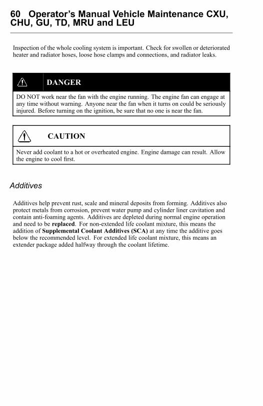
60 Operator’s Manual Vehicle Maintenance CXU,CHU, GU, TD, MRU and LEU
Inspection of the whole cooling system is important. Check for swollen or deterioratedheater and radiator hoses, loose hose clamps and connections, and radiator leaks.
DANGER
DO NOT work near the fan with the engine running. The engine fan can engage atany time without warning. Anyone near the fan when it turns on could be seriouslyinjured. Before turning on the ignition, be sure that no one is near the fan.
CAUTION
Never add coolant to a hot or overheated engine. Engine damage can result. Allowthe engine to cool first.
Additives
Additives help prevent rust, scale and mineral deposits from forming. Additives alsoprotect metals from corrosion, prevent water pump and cylinder liner cavitation andcontain anti-foaming agents. Additives are depleted during normal engine operationand need to be replaced. For non-extended life coolant mixture, this means theaddition of Supplemental Coolant Additives (SCA) at any time the additive goesbelow the recommended level. For extended life coolant mixture, this means anextender package added halfway through the coolant lifetime.
Operator’s Manual Vehicle Maintenance CXU,CHU, GU, TD, MRU and LEU 61
Regular Coolant Change Interval
Coolant SCA level must be tested at least twice per year or whenever coolant lossoccurs. For maximum coolant system efficiency, test the system at every engine oilchange interval, every 1,000 hours or every 6 months (whichever comes first). Forproper SCA levels, consult Service Manual.
Regular Coolant Filter Change Intervals
WARNING
Hot engine. Keep clear of all hot engine parts and fluids. A hot engine and fluidscan cause serious burns.
The charged coolant filter contains 8 units of SCA that are released slowly over timeto maintain the recommended level during operation. Consult engine service manualfor proper SCA level and change intervals.
62 Operator’s Manual Vehicle Maintenance CXU,CHU, GU, TD, MRU and LEU
Extended Life Coolant Change Interval
CAUTION
Extended life coolant will test as out of additives (SCA), but SCA should not beadded. Shortened engine life may be the result of adding SCA.
Note: DO NOT add supplement coolant additives (SCA) to extended life coolant.
Should the extended life coolant system become contaminated with regular coolantexceeding 10% of the systems total capacity or if SCA is added to extended lifecoolant, drain the system and refill with new extended life coolant or regular coolant.
Extended Lift Coolant Filter Change Interval
WARNING
Hot engine. Keep clear of all hot engine parts and fluids. A hot engine and fluidscan cause serious burns.
CAUTION
DO NOT use a filter that contains SCA. Damage to components can result.
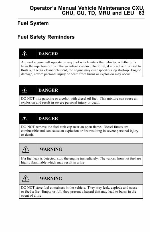
Operator’s Manual Vehicle Maintenance CXU,CHU, GU, TD, MRU and LEU 63
Fuel System
Fuel Safety Reminders
DANGER
A diesel engine will operate on any fuel which enters the cylinder, whether it isfrom the injectors or from the air intake system. Therefore, if any solvent is used toflush out the air cleaner element, the engine may over speed during start-up. Enginedamage, severe personal injury or death from burns or explosion may occur.
DANGER
DO NOT mix gasoline or alcohol with diesel oil fuel. This mixture can cause anexplosion and result in severe personal injury or death.
DANGER
DO NOT remove the fuel tank cap near an open flame. Diesel fumes arecombustible and can cause an explosion or fire resulting in severe personal injuryor death.
WARNING
If a fuel leak is detected, stop the engine immediately. The vapors from hot fuel arehighly flammable which may result in a fire.
WARNING
DO NOT store fuel containers in the vehicle. They may leak, explode and causeor feed a fire. Empty or full, they present a hazard that may lead to burns in theevent of a fire.
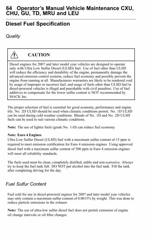
64 Operator’s Manual Vehicle Maintenance CXU,CHU, GU, TD, MRU and LEU
Diesel Fuel Specification
Quality
CAUTION
Diesel engines for 2007 and later model year vehicles are designed to operateonly with Ultra Low Sulfur Diesel (ULSD) fuel. Use of fuel other than ULSDwill reduce the efficiency and durability of the engine, permanently damage theadvanced emission control systems, reduce fuel economy and possibly prevent theengine from running at all. Manufacturers warranties are likely to be rendered voidby usage of improper or incorrect fuel, and usage of fuels other than ULSD fuel indiesel-powered vehicles is illegal and punishable with civil penalties. Use of fueladditives to compensate for the lower sulfur content is NOT recommended byMACK Inc.
The proper selection of fuel is essential for good economy, performance and enginelife. No. 2D ULSD should be used when climatic conditions permit. No. 1D ULSDcan be used during cold weather conditions. Blends of No. 1D and No. 2D ULSDfuels can be used to suit various climatic conditions.
Note: The use of lighter fuels (grade No. 1-D) can reduce fuel economy.
Note: Euro 4 EnginesUltra Low Sulfur Diesel (ULSD) fuel with a maximum sulfur content of 15 ppm isrequired to meet emission certification for Euro 4 emission engines. Using approveddiesel fuel with a maximum sulfur content of 500 ppm in Euro 4 emission engineswill meet all reliability standards.
The fuels used must be clean, completely distilled, stable and non-corrosive. Alwaystry to keep the fuel tank full. DO NOT put alcohol into the fuel tank. Fill the tankafter completing driving for the day.
Fuel Sulfur Content
Fuel sold for use in diesel-powered engines for 2007 and later model year vehiclesmay only contain a maximum sulfur content of 0.0015% by weight. This was done toreduce particle emissions in the exhaust.
Note: The use of ultra-low sulfur diesel fuel does not permit extension of engineoil change intervals or oil filter changes.

Operator’s Manual Vehicle Maintenance CXU,CHU, GU, TD, MRU and LEU 65
Cetane Number
Direct injected diesel engines require a minimum cetane number of 43 under normalstarting conditions. Fuel with a higher cetane value may be required for high-altitudeor cold-weather operation.
Filtration
Fuel should be clean and free of contamination. Clean fuels should have no more than0.05% of sediment and water.
Fuel Additives
Fuel additives are generally not recommended or needed for fuels listed earlier.Cetane improvers can be used as necessary. Biocides may be needed to eliminatemicroorganism growth in storage tanks. In cold conditions, treatment for water inthe vehicle tanks may also be necessary.
Consult your fuel supplier about the use of additives to prevent incompatibility amongadditives already in the fuel and the additives to be used.
Supplemental Fuel Enhancers
CAUTION
Supplemental additives are not recommended because of a high risk of injectionsystem problems or engine damage.
There are many aftermarket products available today which are intended to be addedby the customer. They generally increase operating cost without providing benefits.Included are a variety of independently marketed products which claim to be:
• Cetane improvers• Emission control additives• Detergents• Combustion improvers• Smoke suppressants• Cold weather flow improvers
Note: Repair expenses resulting from malfunctions in the fuel system or with enginecomponents when fuel enhancers have been used are not covered under warranty.
66 Operator’s Manual Vehicle Maintenance CXU,CHU, GU, TD, MRU and LEU
Some fuel additives can be used to provide temporary relief, but they do not replacegood fuel handling practices. These products can be used:
• Isopropyl Alcohol Use 1/2 liter per 450 liters (1 pint per 125 gallons) of fuel forwinter freeze-up protection.
• Biocide For treatment of microbe growth or black slime. Follow manufacturersinstruction for treatment.
Prohibited Additives
WARNING
The addition of gasoline to diesel fuel will create a serious fire hazard. Seriouspersonal injury can result.
The following additives are specifically NOT allowed and must NOT be mixedin with the vehicle diesel fuel:
• Gasoline Adding gasoline to diesel fuel will reduce the cetane number and increasecombustion temperature. If a tank contains a diesel fuel/gasoline mixture, it shouldbe drained and cleaned as soon as possible.
• Used lubricating oil MACK Inc. does not recommend the use of any type of usedlubricating oil as an extender in the diesel fuel. Used lubrication oil containssolids and acids from the combustion process that can severely corrode parts ofthe injection system, resulting in reduced power and higher maintenance costover time.
Alternative Fuels
Alternative fuels can be of several different types. There are vegetable based fuels,aviation fuel and recycled petroleum based fuels that are used in combustion engines.These are in general not compatible with modern heavy-duty over-the-road dieselengines.
The use of unauthorized fuels may compromise the levels of pollutants in the exhaustto the point where the engine does not meet the emission requirements. This wouldmake the vehicle illegal to drive on public roads. DO NOT use any kind of alternativefuel unless specifically authorized by MACK Inc.
Operator’s Manual Vehicle Maintenance CXU,CHU, GU, TD, MRU and LEU 67
Bio Diesel
The only Bio Diesel Fuel approved by MACK Inc. for use in EPA 2010 MACKEngines is Soy Methyl Ester (SME or SOME) in blends up to B5 Concentration(5% blend).
Note: Although higher concentrations are available, concentration up to B5(maximum) are the only blends currently approved by MACK Inc.
Fuel Storage
If fuel is stored on site:
• Keep storage tank covered to prevent water entry.• DO NOT use a tank made of galvanized metal or any galvanized piping for diesel
oil storage. Diesel will react with the zinc, forming solids that can clog fuel filtersand cause engine damage.
• Fuel stored for a long time may oxidize and form solids, causing filtering problems.• Keep the area around the fill cap clean. Tilt the tank slightly toward the drain plug
area so water and sediment can be easily drained.
Generally, fuel contamination occurs as the result of improper fuel handling. The mostcommon types of contamination are water, dirt and microbial growth (black slime).The formation of varnishes and gums resulting from poor fuel stability or long storage(stale fuel) also affects fuel quality. The best treatment for contamination is preventionby maintaining a clean storage system and choosing a reputable fuel supplier.
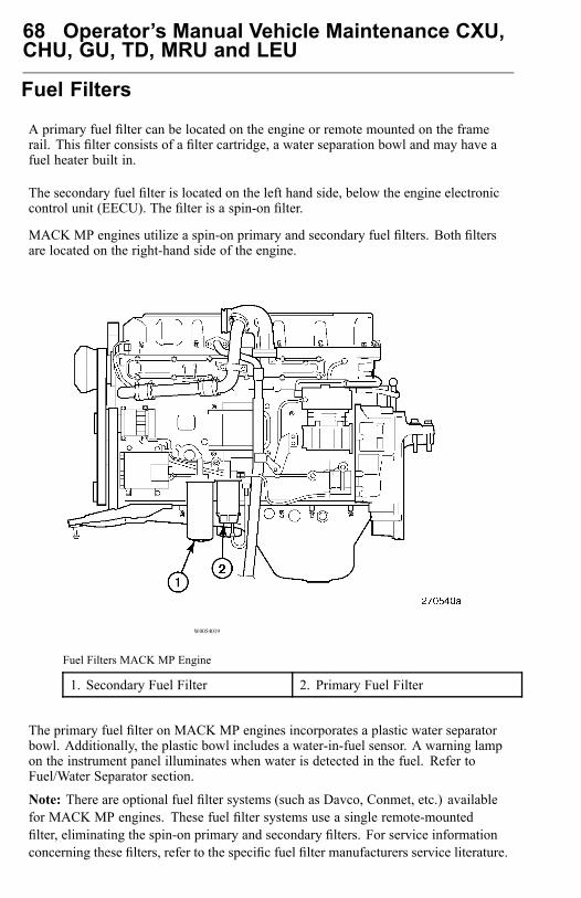
68 Operator’s Manual Vehicle Maintenance CXU,CHU, GU, TD, MRU and LEU
Fuel Filters
A primary fuel filter can be located on the engine or remote mounted on the framerail. This filter consists of a filter cartridge, a water separation bowl and may have afuel heater built in.
The secondary fuel filter is located on the left hand side, below the engine electroniccontrol unit (EECU). The filter is a spin-on filter.
MACK MP engines utilize a spin-on primary and secondary fuel filters. Both filtersare located on the right-hand side of the engine.
W0054019
Fuel Filters MACK MP Engine
1. Secondary Fuel Filter 2. Primary Fuel Filter
The primary fuel filter on MACK MP engines incorporates a plastic water separatorbowl. Additionally, the plastic bowl includes a water-in-fuel sensor. A warning lampon the instrument panel illuminates when water is detected in the fuel. Refer toFuel/Water Separator section.
Note: There are optional fuel filter systems (such as Davco, Conmet, etc.) availablefor MACK MP engines. These fuel filter systems use a single remote-mountedfilter, eliminating the spin-on primary and secondary filters. For service informationconcerning these filters, refer to the specific fuel filter manufacturers service literature.

Operator’s Manual Vehicle Maintenance CXU,CHU, GU, TD, MRU and LEU 69
Primary Fuel Filter Replacement ProceduresMACK MP Engines
At each specified oil and filter change interval, change the primary fuel filter asfollows:
W0054023
MACK MP Primary Fuel Filter
1. Primary Filter2. Water Separator Bowl
3. Water-in-Fuel Sensor Harness4. Drain Assembly
70 Operator’s Manual Vehicle Maintenance CXU,CHU, GU, TD, MRU and LEU
1 Thoroughly wash the area around the fuel filter and mounting adapter mating areawith a suitable solvent and blow dry with compressed air.
2 Disconnect the water-in-fuel sensor harness connector from the plastic waterseparator bowl.
3 Using tool J 24783, remove the primary filter.4 While holding the filter above a suitable container, open the drain valve on the
plastic water separator bowl and allow the fuel in the bowl to drain. Dispose ofthe drained fuel in an environmentally safe manner.
5 Unscrew the plastic separator bowl from the bottom of the spin-on primary filtercartridge.
6 Apply a thin film of clean engine oil to the water separator bowl O-ring on thebottom of the new primary filter cartridge.
7 Install the plastic water separator bowl to the primary filter cartridge, and tightenthe bowl by hand 1/4 to 1/2 turn after the bowl contacts the O-ring.
8 Apply a thin film of clean engine oil to the sealing gasket of the new filter cartridge.9 Prime the filter by pouring clean filter fuel through the series of small holes at the
top of the filter to the installation fill line. DO NOT prime the filter through thecenter hole. Use care to avoid dirt entering the center hole of the filter.
10 Install the new filter and tighten an additional 1/2 to 3/4 turn by hand after thegasket contacts the base.
11 Reconnect the water-in-fuel sensor harness connector.12 Prime the engine as required prior to starting the engine (refer to “Priming the Fuel
System MACK MP Engines”, page 72).13 Start the engine and check for leaks.
Operator’s Manual Vehicle Maintenance CXU,CHU, GU, TD, MRU and LEU 71
Secondary Fuel Filter Replacement Procedures
At each specified oil and filter change interval, change the secondary fuel filter asfollows:
Note: Because of ice buildup in the fuel system or fuel waxing which can clog fuelfilters, it may be necessary to reduce the time or mileage interval between fuel filterchanges during extremely cold weather.
To install a new filter:1 Thoroughly wash the area around the fuel filter and mounting adaptor mating area
with a suitable solvent and blow dry with compressed air.2 Using tool J 24783, remove the old filters.3 Apply a thin film of clean engine oil to the sealing gasket of the new filters.4 Prime the filter by pouring clean filtered fuel through the series of small holes at
the top of the filter. DO NOT prime the filter through the center hole. Use care toavoid dirt entering the center hole of the filter.
5 Install the new filters and tighten an additional 3/4 to 1 turn by hand after thegasket contacts the base.
6 Prime the engine as required prior to starting the engine (refer to “Priming the FuelSystem MACK MP Engines”, page 72).
7 Start the engine and check for leaks.
72 Operator’s Manual Vehicle Maintenance CXU,CHU, GU, TD, MRU and LEU
Priming the Fuel System MACK MP Engines
On MACK MP engines, the priming pump is located on the primary fuel filtermounting adapter. Prime the fuel system as follows:
DANGER
Before working on or inspecting avehicle, apply the parking brakes, placethe transmission in neutral and blockthe wheels to prevent the vehicle frommoving. Failure to do so can resultin unexpected vehicle movement andcause severe personal injury or death.
DANGER
To avoid potential fire hazard, do notservice any part of the fuel systemwhile smoking, or in the presence offlames, sparks or hot surfaces. Donot service the fuel system while theengine is running. Failure to followthese precautions can result in a fire. Toguard against burns from direct contactwith hot fuel, wear adequate protectiveclothing (face shield, heavy gloves,apron, etc.) when working on a hotengine.
WARNING
DO NOT work near the fan while theengine is running. The engine fan canengage at any time without warning,resulting in serious injury. Beforeturning the ignition on, make sure thatno one is near the fan.
Note: There are NO bleed nipples that must be opened in order to prime the fuelsystem.
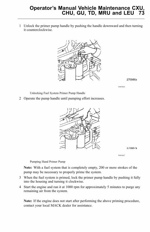
Operator’s Manual Vehicle Maintenance CXU,CHU, GU, TD, MRU and LEU 73
1 Unlock the primer pump handle by pushing the handle downward and then turningit counterclockwise.
W0054026
Unlocking Fuel System Primer Pump Handle
2 Operate the pump handle until pumping effort increases.
W0054027
Pumping Hand Primer Pump
Note: With a fuel system that is completely empty, 200 or more strokes of thepump may be necessary to properly prime the system.
3 When the fuel system is primed, lock the primer pump handle by pushing it fullyinto the housing and turning it clockwise.
4 Start the engine and run it at 1000 rpm for approximately 5 minutes to purge anyremaining air from the system.
Note: If the engine does not start after performing the above priming procedure,contact your local MACK dealer for assistance.
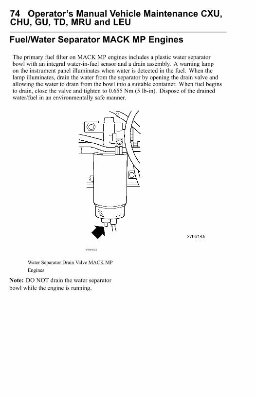
74 Operator’s Manual Vehicle Maintenance CXU,CHU, GU, TD, MRU and LEU
Fuel/Water Separator MACK MP Engines
The primary fuel filter on MACK MP engines includes a plastic water separatorbowl with an integral water-in-fuel sensor and a drain assembly. A warning lampon the instrument panel illuminates when water is detected in the fuel. When thelamp illuminates, drain the water from the separator by opening the drain valve andallowing the water to drain from the bowl into a suitable container. When fuel beginsto drain, close the valve and tighten to 0.655 Nm (5 lb-in). Dispose of the drainedwater/fuel in an environmentally safe manner.
W0054022
Water Separator Drain Valve MACK MPEngines
Note: DO NOT drain the water separatorbowl while the engine is running.
Operator’s Manual Vehicle Maintenance CXU,CHU, GU, TD, MRU and LEU 75
Engine Oil
General
Keep the engine oil at the proper level and change it at the recommended intervals.Always replace the oil filters at the same time as when the oil is changed.
Oil Quality
MACK Inc. recognizes engine oils that meet or exceed the standards given byAmerican Petroleum Institute (API) for the oil classifications listed in this manual.Only oils licensed to carry the API symbol should be used. Lubricants meetingAPI standards have provided maximum engine life when used together with therecommended oil and oil filter change intervals.
EO-O Premium Plus (or VDS-4) diesel engine oil is mandatory for use in all 2010emission compliant MACK engines. Chassis equipped with a 2010 emissioncompliant engine, which can be identified by the presence of a Diesel Particulate Filter(DPF), also require the use of Ultra Low Sulfur Diesel (ULSD) fuel. EO-O PremiumPlus oils exceed the new API service category CJ-4.
CAUTION
DO NOT add extra oil additives. Additives such as break-in oils, top oils,graphitizers, and friction-reducing liquids are not necessary and can harm theengine.
Oil Change Intervals
The length of time an engine can operate before an oil change depends on the qualityoil used, the type of fuel used, fuel consumption, engine oil consumption, vehicleapplication, level of dust in the air, and fuel consumption. The change intervals givenin this manual are maximum intervals. If the vehicle is operating in heavy-dutyoperation, dusty or off-road conditions, etc., reduce the intervals for more frequent oilchanges. For the correct oil change interval, see “Oil Capacity Tables and ViscosityCharts”, page 142.
For additional information about oil change intervals, see your MACK Truck dealer.
For a complete list of approved oils, see your MACK Truck dealer.
Note: Oil filters should always be changed when changing oil.
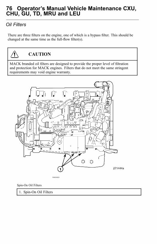
76 Operator’s Manual Vehicle Maintenance CXU,CHU, GU, TD, MRU and LEU
Oil Filters
There are three filters on the engine, one of which is a bypass filter. This should bechanged at the same time as the full-flow filter(s).
CAUTION
MACK branded oil filters are designed to provide the proper level of filtrationand protection for MACK engines. Filters that do not meet the same stringentrequirements may void engine warranty.
W0054029
Spin-On Oil Filters
1. Spin-On Oil Filters
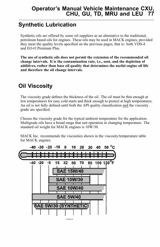
Operator’s Manual Vehicle Maintenance CXU,CHU, GU, TD, MRU and LEU 77
Synthetic Lubrication
Synthetic oils are offered by some oil suppliers as an alternative to the traditional,petroleum based oils for engines. These oils may be used in MACK engines, providedthey meet the quality levels specified on the previous pages, that is: both VDS-4and EO-O Premium Plus.
The use of synthetic oils does not permit the extension of the recommended oilchange intervals. It is the contamination rate, i.e., soot, and the depletion ofadditives, rather than base oil quality that determines the useful engine oil lifeand therefore the oil change intervals.
Oil Viscosity
The viscosity grade defines the thickness of the oil. The oil must be thin enough atlow temperatures for easy cold starts and thick enough to protect at high temperatures.An oil is not fully defined until both the API quality classification and the viscositygrade are specified.
Choose the viscosity grade for the typical ambient temperature for the application.Multigrade oils have a broad range that suit operation in changing temperature. Thestandard oil weight for MACK engines is 10W/30.
MACK Inc. recommends the viscosities shown in the viscosity/temperature tablefor MACK engines.
W1000144
78 Operator’s Manual Vehicle Maintenance CXU,CHU, GU, TD, MRU and LEU
Oil Additives
CAUTION
Extra oil additives must never be added to any engine oil used. Additives such asbreak-in oils, top oils, graphitizers, and friction reducing liquids are not necessaryand may even harm the engine.
Using oils to the quality standards recommended in this manual makes the use ofextra oil additives unnecessary, as these oils already contain a balanced treatmentof additives.
Oil Consumption
Once the engine is stopped, check the oil level daily. If the engine has just beenstopped and it is warm, wait approximately five minutes to allow the oil to drain backto the oil pan before checking. Add oil as necessary.
Note: DO NOT overfill engine with oil.
All diesel engines are designed to consume some oil, so it is normal to add oilperiodically. An engine used in heavy-duty operation will consume more oil thanone in normal operation.
To assist you in measuring your oil usage please refer to the Fuel and Oil Record on“Fuel and Oil Record”, page 155.
Operator’s Manual Vehicle Maintenance CXU,CHU, GU, TD, MRU and LEU 79
Oil Change
WARNING
A hot engine or engine oil can be dangerous. Serious burns can result from contactwith a hot engine or oil. Take precautions when draining the oil. Wear gloves or letthe engine cool down before draining.
WARNING
When draining the oil, use the proper tools and keep away as far as possible. Raisethe elbow so the forearm is parallel to the ground to prevent oil running downthe arm, causing burns.
CAUTION
Always dispose of all lubricants (motor oil, coolant, gear box oils, etc.) andfilters according to Federal or local regulations. Used oil disposed of in nature orwaterways contaminates our drinking water and kills wildlife.
CAUTION
Prolonged contact with used engine oil may be harmful. Use rubber gloves whenhandling used oil. Wash skin thoroughly if it comes in contact with used oil.
For information on the type of oil recommended for your engine, see “Oil Quality”,page 75 and “Oil Capacity Tables and Viscosity Charts”, page 142 for quantities andviscosities, or refer to the engine manufacturers operators manual.
It is important to drain as much oil as possible. Try to change oil immediately afterdriving, when the oil is warm. Always replace the oil filters when changing oil.
80 Operator’s Manual Vehicle Maintenance CXU,CHU, GU, TD, MRU and LEU
Oil Filters Change
WARNING
Hot oil can cause severe burns. DO NOT allow hot oil to contact the skin. Whenchanging oil, wear protective gloves.
CAUTION
MACK-branded oil filters are designed to provide the proper level of filtrationand protection for MACK engines. Filters that do not meet the same stringentrequirements may cause unsatisfactory results.
1 Coat the filter gasket with oil.2 Install the filter and turn it by hand until the gasket makes contact with the sealing
surface.3 Manually turn the filter an additional 3/4 to one full turn.
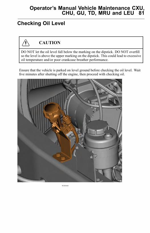
Operator’s Manual Vehicle Maintenance CXU,CHU, GU, TD, MRU and LEU 81
Checking Oil Level
CAUTION
DO NOT let the oil level fall below the marking on the dipstick. DO NOT overfillso the level is above the upper marking on the dipstick. This could lead to excessiveoil temperature and/or poor crankcase breather performance.
Ensure that the vehicle is parked on level ground before checking the oil level. Waitfive minutes after shutting off the engine, then proceed with checking oil.
W2056443
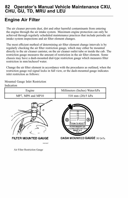
82 Operator’s Manual Vehicle Maintenance CXU,CHU, GU, TD, MRU and LEU
Engine Air Filter
The air cleaner prevents dust, dirt and other harmful contaminants from enteringthe engine through the air intake system. Maximum engine protection can only beachieved through regularly scheduled maintenance practices that include periodic airintake system inspections and air filter element changes.
The most efficient method of determining air filter element change intervals is byregularly checking the air filter restriction gauge, which may either be mounteddirectly to the air cleaner canister, on the air cleaner outlet tube or inside the cab. Therestriction gauge measures the amount of restriction in the air filter element. Somechassis may have a dash-mounted dial-type restriction gauge which measures filterrestriction in mm/inchesof water.
Change the air filter element in accordance with the procedures as outlined, when therestriction gauge red signal locks in full view, or the dash-mounted gauge indicatesinlet restriction as follows:
Mounted Gauge Inlet RestrictionIndication
Engine Millimeters (Inches) Water/kPa
MP7, MP8 and MP10 510 mm (20)/5 kPa
W0054007
Air Filter Restriction Gauge
Operator’s Manual Vehicle Maintenance CXU,CHU, GU, TD, MRU and LEU 83
Damage to the air filter element, such as holes in the filter medium, will give aninaccurate restriction reading. Therefore, even if maximum restriction is not indicated,the air filter element should be changed yearly or at 160 000 Km (100,000 mile)intervals, whichever comes first.
When replacing the air filter element, or whenever the air inlet system has beendisassembled, inspect the inlet air ducts between the air cleaner canister outlet and theturbocharger inlet as follows:• Inspect the rubber elbows for cracks, splitting and/or holes. Rubber components
must be flexible so that they conform to the plastic ducts and ensure a tight seal.• Inspect plastic ducts for cracks and/or holes.• Ensure that all hose clamps are properly installed and tightened to specifications.• Make sure the plastic ducts do not rub against any components such as air
conditioning hoses, wire harnesses, etc.
To properly install a new filter element:1 Wipe the air cleaner housing clean.2 Remove the filter element(s).3 Inspect sealing areas for dirt tracks which would indicate that dust has leaked past
the seal. If dirt tracks are found, the cause must be determined and corrected.4 Thoroughly clean the inside of the air cleaner canister with a damp cloth or
vacuum cleaner.5 If equipped with a metal canister, inspect inside the canister for rust. If rust is
present:1 Remove the air cleaner canister from the chassis.2 Remove all loose rust with a wire brush or a coarse Scotch Brite pad.3 Sand with 180/240 grit wet or dry sand paper.4 Thoroughly wash the area with PPG DX-440, DX-436, DX-437 or equivalent,
wax and grease remover and wipe dry.5 Prime immediately with PPG DEP-351 epoxy primer.6 Reinstall the air cleaner canister.
6 Inspect the sealing areas of the housing for damage. Repair or replace as necessary.7 Use MACK-approved replacement elements and gaskets. Make sure the new
elements and gaskets are not damaged. Be sure to use new gaskets each time theelement is changed. Install the cover and, depending upon cover configuration,tighten as follows:• Air cleaner with large wing nut in center of cover hand-tighten wing nut.• Air cleaner with three thumb screws around outer edge of cover hand-tighten
thumb screws.• Air cleaner with retaining nuts around outer edge of cover tighten retaining nuts
between 11 – 14 Nm (8 – 10 lb-ft).

84 Operator’s Manual Vehicle Maintenance CXU,CHU, GU, TD, MRU and LEU
Note: DO NOT attempt to clean the air filter element with compressed air, as thiscould damage the filter medium and possibly result in severe engine damage.
W0053982
Replacement Parts and Filters

Operator’s Manual Vehicle Maintenance CXU,CHU, GU, TD, MRU and LEU 85
Exhaust After-Treatment System
CHU, CXU, GU and TD Standard System View
W2029933
1. Selective Catalytic Reduction (SCR)Catalyst
2. Aftertreatment DEF Dosing Unit
3. Aftertreatment Diesel ParticulateFilter (DPF)
4.Aftertreatment DEF Tank
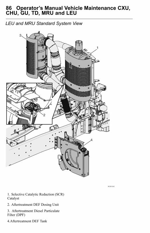
86 Operator’s Manual Vehicle Maintenance CXU,CHU, GU, TD, MRU and LEU
LEU and MRU Standard System View
W2031562
1. Selective Catalytic Reduction (SCR)Catalyst
2. Aftertreatment DEF Dosing Unit
3. Aftertreatment Diesel ParticulateFilter (DPF)
4.Aftertreatment DEF Tank
Operator’s Manual Vehicle Maintenance CXU,CHU, GU, TD, MRU and LEU 87
DANGER
The SCR/DPF shield should not beremoved while the vehicle is in use.Also, only remove the shield, once thevehicle is out of use and the SCR/DPFis sufficiently cooled. Failure to followthese instructions can result in fire,which can cause component damage,personal injury or death.
CAUTION
The Diesel particulate filters and theircomponents, can not be moved oraltered from the OEM installation inany fashion. Any alterations may causecomponent damage and is prohibited bythe law.
Check if the vehicle is equipped with a Diesel Particulate Filter (DPF) or a DPFand Selective Catalytic Reduction unit (SCR). These components are part of theoverall vehicle emissions control system. In normal operation, these components canexperience surface temperatures as high as 350° C (662° F). It is important to verifythe temperature at which the material or substance in, or associated with, the body canignite. If it is possible for the material or substance to fall or leak from the body, takesteps to prevent them from contacting or collecting on the DPF or SCR. Failure todo so may result in fire.
It is important to note that additional shielding may, depending upon conditions andthe material or substance, trap flammable substances between the additional shieldand the DPF/SCR. If this condition can develop, advise the user of the vehicle toperiodically check to ensure there are no trapped substances.
Note: The DPF/SCR and associated components are part of a U.S. EPA andCalifornia Air Resources Board (CARB) certified engine emissions system. Thesecomponents must not be moved, altered or modified in any way. Tampering withthese systems render the emissions warranty void and may result in possibletampering charges by the EPA or CARB.
88 Operator’s Manual Vehicle Maintenance CXU,CHU, GU, TD, MRU and LEU
New stringent standards for exhaust emission control begin with the 2010 model year.The Diesel Particulate Filter (DPF) system has been developed to act in combinationwith Ultra Low Sulphur Diesel (ULSD) fuel to reduce particulate emissions to meetthe requirement. The Exhaust After-Treatment System (EATS) includes all the engineand exhaust emissions control components that are required to meet the stringent2010 standard.
Particulate matter consists of soot and ash in the exhaust that engines with an EGRsystem alone, are not equipped to handle. The particulate matter is considereda contaminant that contains undesirable elements. The DPF system reduces theunwanted elements to a more acceptable level defined in the regulations. There aremultiple methods of reducing these emissions. MACK has selected to use a DieselOxidation Catalyst (DOC) with a catalyzed diesel particulate filter. The other usesa diesel particulate filter of a different kind without a DOC and in its place uses acombustion chamber to heat the exhaust mixture thus causing active regeneration.
The particulate matter removed from the exhaust collects on the filter surfaces. Toavoid eventual blockage, which would increase exhaust back pressure and affect powerand fuel economy, the filter must be cleaned. The DPF is cleaned automatically. Thesoot breaks down to safer substances before being released to the atmosphere. Someof the ash remains, but takes a long time to reach the point where ash clogs the filter.
Cleaning a filter so it can continue to function is called “regeneration.” Either systemuses high heat to break down the chemical properties. Depending on vehicle usage,the engine is equipped with a passive or active regeneration system.
In “passive regeneration,” the exhaust produces enough heat continuously to convertthe soot, with approximately 260 °C (500 °F) being required. The process is slow andcontinues indefinitely. Passive regeneration is possible only in vehicle applicationswhere the temperature is likely to remain at or above the required temperature level,making active regeneration unnecessary.
During an active regeneration, the temperature of the filter must be raised to 500 °C(932 °F). To produce this temperature, the system uses a hydrocarbon injector orAftertreatment Fuel (AF) injector to introduce fuel into the exhaust stream as it leavesthe turbocharger. The hot exhaust ignites the fuel which produces the regenerationtemperature. When the DPF becomes restricted to a minimum volume, the engineECU starts the fuel injection into the exhaust. When the air flow rate returns to normalthrough the DPF, the engine ECU turns the injector off.
WARNING
Prior to ever working on the exhaust,allow time for the entire exhaust systemto cool. Failure to do so may result inpersonal injury. Severe burns can occur.
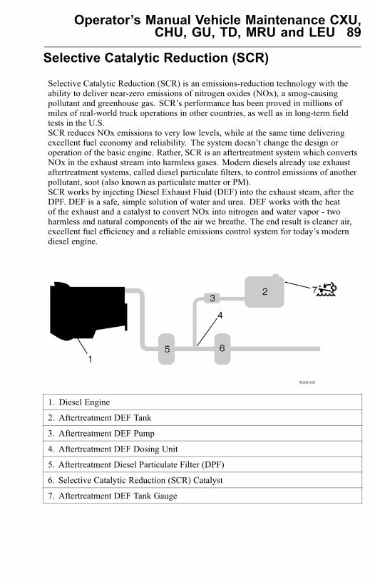
Operator’s Manual Vehicle Maintenance CXU,CHU, GU, TD, MRU and LEU 89
Selective Catalytic Reduction (SCR)
Selective Catalytic Reduction (SCR) is an emissions-reduction technology with theability to deliver near-zero emissions of nitrogen oxides (NOx), a smog-causingpollutant and greenhouse gas. SCR’s performance has been proved in millions ofmiles of real-world truck operations in other countries, as well as in long-term fieldtests in the U.S.SCR reduces NOx emissions to very low levels, while at the same time deliveringexcellent fuel economy and reliability. The system doesn’t change the design oroperation of the basic engine. Rather, SCR is an aftertreatment system which convertsNOx in the exhaust stream into harmless gases. Modern diesels already use exhaustaftertreatment systems, called diesel particulate filters, to control emissions of anotherpollutant, soot (also known as particulate matter or PM).SCR works by injecting Diesel Exhaust Fluid (DEF) into the exhaust steam, after theDPF. DEF is a safe, simple solution of water and urea. DEF works with the heatof the exhaust and a catalyst to convert NOx into nitrogen and water vapor - twoharmless and natural components of the air we breathe. The end result is cleaner air,excellent fuel efficiency and a reliable emissions control system for today’s moderndiesel engine.
W2031651
1. Diesel Engine
2. Aftertreatment DEF Tank
3. Aftertreatment DEF Pump
4. Aftertreatment DEF Dosing Unit
5. Aftertreatment Diesel Particulate Filter (DPF)
6. Selective Catalytic Reduction (SCR) Catalyst
7. Aftertreatment DEF Tank Gauge
90 Operator’s Manual Vehicle Maintenance CXU,CHU, GU, TD, MRU and LEU
CAUTION
Do not put diesel fuel in theAftertreatment DEF tank. Dieselfuel, if sprayed into the hot exhaustalong with the DEF, could igniteexplosively causing a fire resultingin personal injury or damage to theexhaust system.
There are two different configurations for the SCR catalysts, they are vertical andhorizontal. The horizontal SCR catalyst comes in two different sizes, one for theMP7/MP8 engines and larger size for the MP10 engine. The vertical SCR catalystalso comes in two different sizes, one for the MP7/MP8 engines and larger size for theMP10 engine.The MACK SCR system is simple and effective, with few components. It consistsof a Aftertreatment DEF tank positioned near the standard diesel tank, plus aAftertreatment DEF pump, Aftertreatment DEF Dosing unit and SCR catalyst. Theadvantage of using DEF is that it enables the engine to use less EGR -- and higheroxygen levels -- for better combustion, while meeting the EPA near-zero NOxemissions requirement of 0.2 g/hp-hr NOx. By using DEF, we avoid the disadvantagesof increasing EGR to massive levels. This results in better fuel economy from yourMACK engine.

Operator’s Manual Vehicle Maintenance CXU,CHU, GU, TD, MRU and LEU 91
Diesel Exhaust Fluid (DEF)
Diesel Exhaust Fluid (DEF) is a reactant that’s key to the SCR process. It’s a nontoxic,aqueous solution of urea and water. Urea is a compound of nitrogen that turns toammonia when heated. It is used in a variety of industries, perhaps most commonlyas a fertilizer in agriculture. The fluid is not flammable, nor is it dangerous whenhandled normally. However, it is highly corrosive to metal, particularly copper andaluminium. Read the separate section concerning the handling of DEF solution. Onlyuse approved DEF fluid.
W3036787
92 Operator’s Manual Vehicle Maintenance CXU,CHU, GU, TD, MRU and LEU
Diesel Exhaust Fluid (DEF) Handling
When handling DEF solution, it is important that electrical connectors to be connectedor well encapsulated. Otherwise there is a risk that the DEF will cause oxidation thatcannot be removed. Water or compressed air do not help, since DEF quickly oxidizesmetal. If a connector comes into contact with the DEF solution it must be replacedimmediately to prevent the DEF solution from creeping further into the copper wiring,which takes place at a speed of about 60 cm (2.4 in) per hour.
CAUTION
When detaching hoses and components,do not spill DEF on disconnectedconnectors. If DEF is spilled on aconnector, the connector must bereplaced immediately
Things to know about spilled Diesel Exhaust Fluid (DEF)
If urea solution comes into contact with the skin, rinse with plenty of water andremove contaminated clothing.
If urea solution comes into contact with the eyes rinse for several minutes and callfor medical help if necessary.
If inhaled breathe fresh air and call for medical help if necessary.
Do not allow the DEF solution to come into contact with other chemicals.
The DEF solution is not flammable. If the DEF solution is exposed to hightemperatures, it breaks down into ammonia and carbon dioxide.
The DEF solution is highly corrosive to certain metals, including copper andaluminium.
If the DEF solution is spilled onto the vehicle, wipe off the excess and rinse withwater. Spilled DEF solution can form concentrated white crystals on the vehicle.Rinse off these crystals with water.
Note: Do not flush DEF spills into the normal drain system.
WARNING
DEF spilt onto hot components willquickly vaporize. Turn your face away!
Operator’s Manual Vehicle Maintenance CXU,CHU, GU, TD, MRU and LEU 93
Diesel Exhaust Fluid (DEF) Consumption
DEF consumption is related to fuel consumption. A highway truck may travel225-300 miles or more on one gallon of DEF. A gauge much like a fuel gauge willindicate the level of DEF in the tank. A DEF low-level warning will activate whenDEF is low. If a driver runs out of DEF completely, vehicle power will be reduced toderate mode. When the DEF tank is refilled, the engine will resume normal power.
Note: DEF tanks are sized for a two to one fuel to DEF ratio in order to meet EPA2010 requirements.
Diesel Exhaust Fluid (DEF) Availability
DEF will be available in 2.5 gallon containers, 55 gallon drums, 275 gallon IBC andin bulk storage for fleet locations, truck stops and dealerships. All major truck stops,dealers and distributors will carry DEF. For more information on DEF and availabilityplease visit the website www.Mackscr.com.
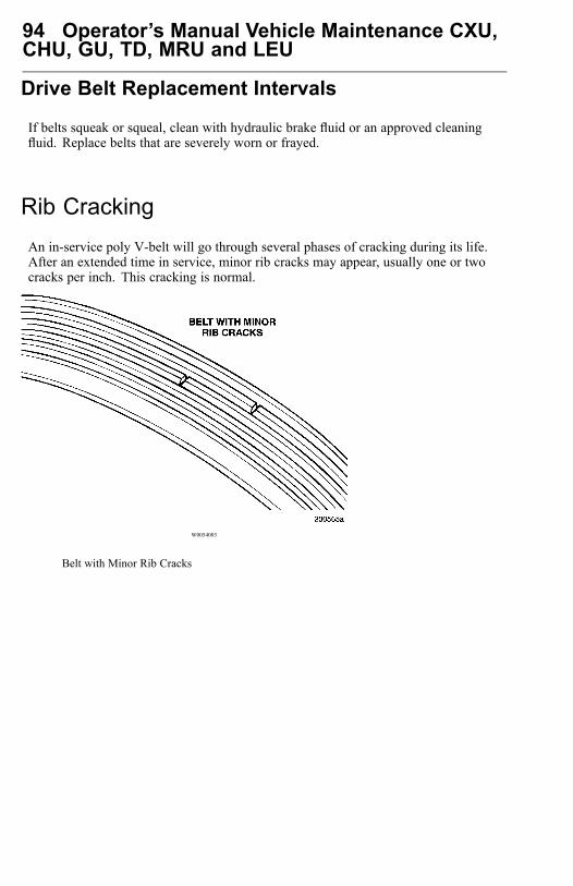
94 Operator’s Manual Vehicle Maintenance CXU,CHU, GU, TD, MRU and LEU
Drive Belt Replacement Intervals
If belts squeak or squeal, clean with hydraulic brake fluid or an approved cleaningfluid. Replace belts that are severely worn or frayed.
Rib CrackingAn in-service poly V-belt will go through several phases of cracking during its life.After an extended time in service, minor rib cracks may appear, usually one or twocracks per inch. This cracking is normal.
W0054003
Belt with Minor Rib Cracks

Operator’s Manual Vehicle Maintenance CXU,CHU, GU, TD, MRU and LEU 95
Belts should not be replaced unless the ribs exhibit severe multiple cracking as shownbelow. Multiple cracking will lead to rib chunking.
W0054004
Belt with Multiple Cracking
W0054005
Belt with Severe Cracking and RibChunking

96 Operator’s Manual Vehicle Maintenance CXU,CHU, GU, TD, MRU and LEU
Rib Sidewall GlazingWhen the belt ribs appear to have a shiny surface that is hard and brittle, it is usuallyan indication of belt slippage. This is attributed to inadequate tension and/or extremetemperature. Both these conditions will lead to severe cracking and belt failure,often with little advance warning. If this occurs, locate the cause and correct beforeinstalling a new belt.
Belt WearAccelerated wear on any part of the belt (fabric backing, tensile cord or rib rubber)is a concern and should be investigated for cause, and corrected before installing anew belt.
Possible Causes of Accelerated Belt Wear• Drive Misalignment Belt performance will be adversely affected when
misalignment exceeds 1/16 inch for every 12 inches of belt span.• Belt Length Must be correct.• Environmental Conditions Temperature, exposure to engine fluids, etc.• Abrasive Materials Small stones, metal shavings, etc.
W0054006

Operator’s Manual Vehicle Maintenance CXU,CHU, GU, TD, MRU and LEU 97
Foreign ObjectsAny object protruding in the path of the belt drive and contacting the belt will causedamage and eventual failure. Locate the object before installing a new belt. (See )
W0054011
Damage from Object Protruding in BeltPath
Noise, Vibration and Harshness (NVH)Poly V-belt drive systems were designed to prevent Noise, Vibration and Harshness(NVH) problems. Field problems, however, which may be related to NVH causesoccasionally occur.
98 Operator’s Manual Vehicle Maintenance CXU,CHU, GU, TD, MRU and LEU
Possible Causes
Insufficient belt tension may create a high-pitched howl (squeal) or rasping soundduring engine acceleration or deceleration.
Misalignment may cause a chirping noise, especially at, or near, idle speed. Rigidbracketing of accessories is a must for reasonably vibration-free belt spans. Some spanvibration is to be expected during the range of engine speed and accessory loading.
WARNING
Failure to follow recommendedapplication information andrecommended procedures forinstallation, care maintenance andstorage of belts may result in failureto perform properly and may result indamage to property and serious bodilyinjury. Make sure the belt selected forany application is recommended forthat service.
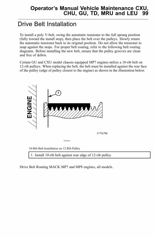
Operator’s Manual Vehicle Maintenance CXU,CHU, GU, TD, MRU and LEU 99
Drive Belt InstallationTo install a poly V-belt, swing the automatic tensioner to the full sprung position(fully toward the install stop), then place the belt over the pulleys. Slowly returnthe automatic tensioner back to its original position. Do not allow the tensioner tosnap against the stops. For proper belt routing, refer to the following belt routingdiagrams. Before installing the new belt, ensure that the pulley grooves are cleanand free of debris.
Certain GU and CXU model chassis equipped MP7 engines utilize a 10-rib belt on12-rib pulleys. When replacing the belt, the belt must be installed against the rear faceof the pulley (edge of pulley closest to the engine) as shown in the illustration below.
W0054031
10-Rib Belt Installation on 12-Rib Pulley
1. Install 10-rib belt against rear edge of 12-rib pulley.
Drive Belt Routing MACK MP7 and MP8 engines, all models.
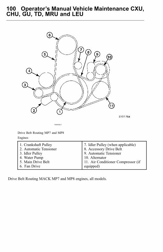
100 Operator’s Manual Vehicle Maintenance CXU,CHU, GU, TD, MRU and LEU
W0054017
Drive Belt Routing MP7 and MP8Engines
1. Crankshaft Pulley2. Automatic Tensioner3. Idler Pulley4. Water Pump5. Main Drive Belt6. Fan Drive
7. Idler Pulley (when applicable)8. Accessory Drive Belt9. Automatic Tensioner10. Alternator11. Air Conditioner Compressor (ifequipped)
Drive Belt Routing MACK MP7 and MP8 engines, all models.
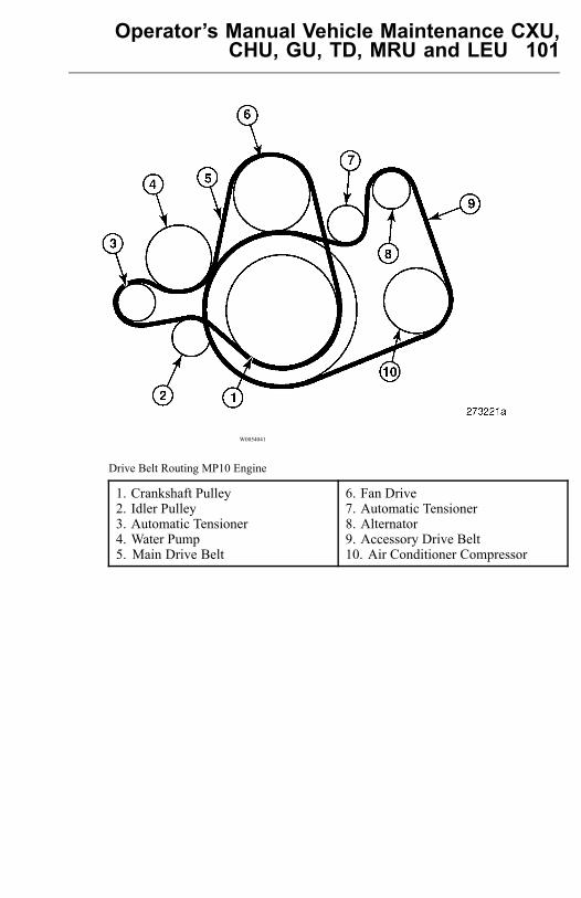
Operator’s Manual Vehicle Maintenance CXU,CHU, GU, TD, MRU and LEU 101
W0054041
Drive Belt Routing MP10 Engine
1. Crankshaft Pulley2. Idler Pulley3. Automatic Tensioner4. Water Pump5. Main Drive Belt
6. Fan Drive7. Automatic Tensioner8. Alternator9. Accessory Drive Belt10. Air Conditioner Compressor
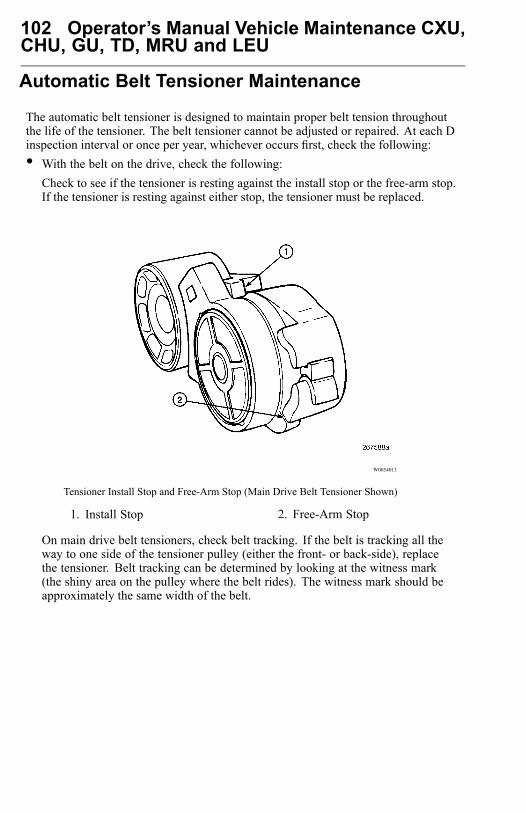
102 Operator’s Manual Vehicle Maintenance CXU,CHU, GU, TD, MRU and LEU
Automatic Belt Tensioner Maintenance
The automatic belt tensioner is designed to maintain proper belt tension throughoutthe life of the tensioner. The belt tensioner cannot be adjusted or repaired. At each Dinspection interval or once per year, whichever occurs first, check the following:• With the belt on the drive, check the following:
Check to see if the tensioner is resting against the install stop or the free-arm stop.If the tensioner is resting against either stop, the tensioner must be replaced.
W0054013
Tensioner Install Stop and Free-Arm Stop (Main Drive Belt Tensioner Shown)
1. Install Stop 2. Free-Arm Stop
On main drive belt tensioners, check belt tracking. If the belt is tracking all theway to one side of the tensioner pulley (either the front- or back-side), replacethe tensioner. Belt tracking can be determined by looking at the witness mark(the shiny area on the pulley where the belt rides). The witness mark should beapproximately the same width of the belt.

Operator’s Manual Vehicle Maintenance CXU,CHU, GU, TD, MRU and LEU 103
W0054014
Main Drive Belt Tensioner Belt Tracking Witness Mark
1. Acceptable (Witness MarkApproximately Same Width as Belt)
2. Not Acceptable (Witness MarkTracking Off Edge of Pulley)
• Remove the belt by using a 3/8 inch breaker bar to pull the tensioner back to theinstall stop. Slowly return the tensioner to the free-arm stop.
• With the belt removed, use the breaker bar to slowly pull the tensioner from thefree-arm stop to the install stop and then slowly releasing it back to the free-armstop. Any excessive roughness or hesitancy noticed while performing this checkindicates that the tensioner must be replaced.
• Check for metal-to-metal contact as follows:Check for contact between the arm and the spring case. Replace if metal-to-metalcontact is seen.
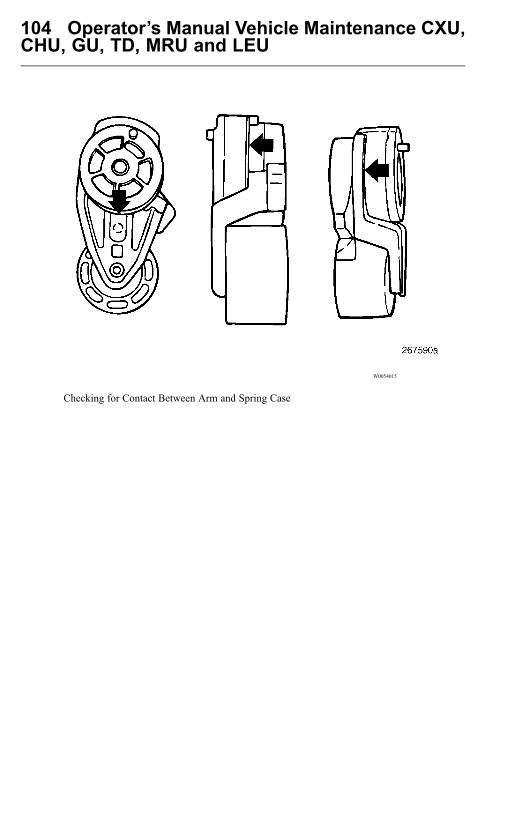
104 Operator’s Manual Vehicle Maintenance CXU,CHU, GU, TD, MRU and LEU
W0054015
Checking for Contact Between Arm and Spring Case

Operator’s Manual Vehicle Maintenance CXU,CHU, GU, TD, MRU and LEU 105
Check for metal-to-metal contact between the arm and the end cap. Replace if contactis seen.
W0054016
Checking for Contact Between Arm and End Cap
Check for cracks in the tensioner body or for broken stops on the spring case. If eitheris seen, replace the tensioner.Reinstall the belt making sure that the belt is properly seated in the grooves of ALLpulleys.
CAUTION
If an automatic belt tensioner must bereplaced, make sure that the propertensioner is used. Tensioner springtension varies by engine and chassismodel. Do not substitute one tensionerpart number for another, as drive beltfailure can result.
106 Operator’s Manual Vehicle Maintenance CXU,CHU, GU, TD, MRU and LEU
Turbocharger and Charge Air Cooler
DANGER
If oil leaks internally from theturbocharger to the engine intake, theoil acts as a fuel. Watch for excessiveexhaust smoke. DO NOT operateengine until problem is corrected. Thereis no way to regulate the engine speedif it runs on oil and it may over speed.Loss of control of vehicle may lead toan accident causing severe personalinjury or death.
WARNING
DO NOT remove, attach, or tightenturbocharger air intake ducting whilethe engine is operating, or operate theengine while the ducting is removed.Working around the turbocharger withthe ducting removed may cause severepersonal injury.
Visually inspect turbo mountings, intake and exhaust ducting and connections forleaks on a daily basis. Check oil inlet and outlet for leaks or signs of restrictions to oilflow. Check for unusual noise or vibration. If any faults are detected, do not operatethe engine until the cause is determined and repaired.
Operator’s Manual Vehicle Maintenance CXU,CHU, GU, TD, MRU and LEU 107
Cleaning Charge Air Cooler and Radiator Package
WARNING
Always wear eye protection whencleaning radiator, charge-air coolerand condenser. Failure to follow thisrecommendation may result in eyeinjury.
CAUTION
When using a pressure washer to cleanthe vehicle, do not direct the spray atelectrical components in the enginecompartment such as the alternator,starter and compressors. Water sprayfrom pressure washers can damageelectrical components.
Periodically inspect the front of the radiator/charge-air-cooler package for buildupof dirt, mud, insects, etc. Over time, there may be a build-up of dirt, mud, insects,etc., between the radiator and charge air cooler. Inspect for build-up and contact yourauthorized MACK Truck dealer, if necessary.
Over time, dirt and insects will accumulate between the fins of the radiator, airconditioning condenser and charge-air-cooler. The reduced air flow reduces the heattransfer from the components to the air. This increases the load on the fan and airconditioning compressor and can result in engine overheating and other performancerelated problems, such as high fuel consumption, etc.
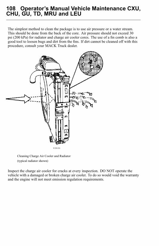
108 Operator’s Manual Vehicle Maintenance CXU,CHU, GU, TD, MRU and LEU
The simplest method to clean the package is to use air pressure or a water stream.This should be done from the back of the core. Air pressure should not exceed 30psi (200 kPa) for radiator and charge air cooler cores. The use of a fin comb is also agood tool to loosen bugs and dirt from the fins. If dirt cannot be cleaned off with thisprocedure, consult your MACK Truck dealer.
W2001496
Cleaning Charge Air Cooler and Radiator(typical radiator shown)
Inspect the charge air cooler for cracks at every inspection. DO NOT operate thevehicle with a damaged or broken charge air cooler. To do so would void the warrantyand the engine will not meet emission regulation requirements.

Operator’s Manual Vehicle Maintenance CXU,CHU, GU, TD, MRU and LEU 109
Preventive Maintenance Air SuspensionsNote: The following maintenance items should be performed on all air suspensions(including MACK AL, AL II, AL-401LH, MAXAIR 40/40A, MAXLITE 2040,MAXLITE 2040 EZ and Hendrickson PRIMAAX) at each B, C and D inspectioninterval, or every 40 234 Km (25,000 miles) or six months, whichever comes first.• Visual Inspection: Inspect all suspension components, checking for signs of
wear, damage or unwanted movement. Loof for bent or cracked parts. Replace allworn or damaged components as required.
• Air Spring: Inspect for chafing or any signs of spring or components damage.Ensure that the upper bead plate is tight against the underside of the frame. Checkfor lateral slippage at the lower air spring bracket. Slippage of 3.3 mm (1/8 inch) ineither direction is acceptable. Replace worn or damaged components as required.
• Support Beam Assembly: Inspect the overall condition of the support beam fordents, dings or other damage. On Hendrickson PRIMAAX suspensions, check theD-pin bushings for tearing or extreme bulging. Check for metal-to-metal contact inthe bushed joints. Replace worn or damaged components as required.
• Frame Hanger Bracket: Inspect for any signs of loosening or damage. OnHendrickson PRIMAAX suspension, check for loosening or damage at theQUIK-ALIGN connections or longitudinal torque rod connections. Replace wornor damaged components as required.
• Cross Beam: Inspect for cracks, damage, metal shavings or looseness at the beamconnections. Replace worn or damaged components as required.
• Transverse Torque Rods: Inspect for signs of looseness at the transverse torquerod connections. Check bushings for tearing or excessive bulging. Check thetransverse torque rod for dents or bending. Replace worn or damaged componentsas required.
• Shock Absorbers: Inspect for signs of dents or leaking (oil misting is notconsidered leakage). Replace worn or damaged shocks as required.
• Tire Wear: Inspect tires for wear patterns that might indicate suspension damageor misalignment. Replace worn or damaged components as required.
• Height Control Valve and Air Lines: Check for loose, bent or damaged parts.Check air lines for chafing or any unwanted contact with moving components.Check height control valve and air lines for leakage. Replace worn or damagedcomponents as required.
110 Operator’s Manual Vehicle Maintenance CXU,CHU, GU, TD, MRU and LEU
Steering and Brakes Maintenance
Steering System
Excessive play in the steering system is checked by turning the steering wheel whilethe engine is stopped. With the front wheels pointing straight ahead, turn the steeringwheel until the front wheel starts moving. Then, turn the steering wheel the other wayuntil the front wheel moves. Play should not be more than 25 mm (1 in) at the rim ofthe steering wheel. If the steering play is excessive, check the steering linkage forlooseness, wear, etc. Make necessary repairs before driving the vehicle.
Power Steering Fluid Reservoir
The power steering fluid reservoir is filled with Automatic Transmission Fluid (ATF)Dexron III for the power steering system. If the fluid has darkened, it indicates thatthe power steering system is running hotter than normal and the fluid is overheating.Take the vehicle to a MACK Truck dealer for troubleshooting the overheating and tohave the fluid changed.

Operator’s Manual Vehicle Maintenance CXU,CHU, GU, TD, MRU and LEU 111
Brake System
DANGER
DO NOT use replacement parts anywhere in the brake system unless it conformsexactly to original specifications. A nonconforming part in your vehicles brakesystem could cause a malfunction, leading to loss of control of the vehicle resultingin severe personal injury or death.
DANGER
DO NOT release the parking brake or attempt to move the vehicle until brakeair pressure in both circuits is at least 100 psi (690 kPa). Failure to follow thisprocedure may lead to uncontrolled vehicle movement and cause severe personalinjury or death.
DANGER
Automatic slack adjusters MUST NOT be manually adjusted in an effort to correctexcessive push rod stroke, as this condition indicates that a problem exists with theautomatic adjuster, installation of the automatic slack adjuster or problems relatedto components of the foundation brakes. These conditions will not be corrected bymanually adjusting the automatic slack adjusters.Manual adjustment of automatic slack adjusters is a dangerous practice that couldresult in serious consequences. This practice gives the vehicle operator a falsesense of security about the effectiveness of the brakes, and the brakes will likelysoon be out of adjustment again.
Note: The brake system is a critical vehicle safety system. For your safety and forthose around you, follow the recommended preventive maintenance checks. If anyproblems occur, have them investigated immediately by an authorized service facility.
The following Dual Circuit Brake System Function Test should be performed at eachC and D inspection interval, or after any air system service procedures that involvedisconnecting and reconnecting air lines where incorrect reconnection, such as thetreadle valve, is a possibility.1 Block the wheels to prevent the vehicle from moving.2 Start the engine and build air system pressure to governor cutout.3 Stop the engine.4 Completely drain one air reservoir.5 Release the parking brakes.6 Apply and hold the treadle valve.
112 Operator’s Manual Vehicle Maintenance CXU,CHU, GU, TD, MRU and LEU
7 Have an assistant check for proper results by observing the movement of the slackadjusters as indicated below:TRUCK:• The brakes on the rear drive axle(s) should always apply as indicated by
movement of the slack adjuster.• The low-air warning buzzer and warning lamp should activate for at least two
of the tests.TRACTOR:
• The brakes on either the steering axle or the rear drive axle(s) should alwaysapply as indicated by movement of the slack adjuster.
• The low-air warning buzzer and warning lamp should activate for at least twoof the tests.
8 Repeat the above procedures for the remaining air reservoirs (do not include airreservoirs for air starter if so equipped).
Air Tanks
DANGER
Drain the air system tanks at the recommended intervals. If condensationaccumulates, moisture can enter the brake system air valves, causing corrosion orclogging. The safety of the brake system could be compromised, leading to anaccident causing severe personal injury or death.
WARNING
When draining the air tanks, DO NOT look into the area of the draining air. Dirt orsludge particles may be in the air stream that could cause eye injury.
Air tanks should be drained daily. Make sure the drain cocks close properly afterdraining. Empty moisture from air tanks by pulling the drain valve lanyard or pullcord. The tanks should be checked for condensation fluid, even if an automatic drainvalve is installed.
It is very important that the air system is kept clean. If sludge or oil is found inthe drainage or an excessive amount of fluid is drained out of the tanks see yourauthorized MACK Truck dealer.
Operator’s Manual Vehicle Maintenance CXU,CHU, GU, TD, MRU and LEU 113
Air Dryers
Effective mid-September 2008, all MACK chassis are equipped with air dryerswhich utilize an oil coalescing desiccant cartridge which removes atomized oil andother particulate matter from the air system. The oil coalescing desiccant cartridgemust be changed yearly. Refer to the specific air dryer service literature for detailedinformation.
114 Operator’s Manual Vehicle Maintenance CXU,CHU, GU, TD, MRU and LEU
Tires, Wheels and Hub Maintenance
Wheel Safety Information
DANGER
DO NOT attempt to repair wheels or tires unless you are trained and equipped todo so. Wheel and tire assemblies cannot be worked on without proper tools andequipment. Failure to follow this may lead to serious personal injury or death.
DANGER
Failure to properly torque-tighten the wheel nuts can result in the breakage ofwheel studs and the subsequent loss of wheels. Loss of vehicle control and seriouspersonal injury or death can occur.
DANGER
DONOT use oil or grease on studs or nuts. The tightening torque is affected and canlead to incorrect clamping loads between the rim and hub. This could lead to a lossof the wheel. Loss of vehicle control and serious personal injury or death can occur.
DANGER
DO NOT install regrooved, retreaded or repaired tires on the steering axle(s). Theycould fail unexpectedly and cause the loss of vehicle control, leading to seriouspersonal injury or death.
DANGER
DO NOT use mismatched wheel components. If they do not exactly match theoriginal design specifications, they may cause failure or separation leading toblowout and an accident and personal injury or death.

Operator’s Manual Vehicle Maintenance CXU,CHU, GU, TD, MRU and LEU 115
DANGER
DO NOT install tires with a load rating that is less than stated on the CertificationLabel in the door frame. The tire could be unintentionally overloaded, leading toan accident, causing serious personal injury or death.
DANGER
DO NOT use mismatched tires on the same axle. Always use the same type (radialor bias ply) or size. Mixing tires on the same axle will affect the roadholding andcan lead to an accident, and serious personal injury or death.
Wheels
DANGER
Before checking the wheels, set the parking brakes, place the transmission inneutral and chock the wheels. Failure to do so can result in unexpected vehiclemovement and can cause serious personal injury or death.
DANGER
Wheels must be serviced only by a qualified technician. DO NOT do this workyourself. Inflated tires on wheels contain compressed air and if suddenly released,do so with an explosive force, resulting in serious personal injury or death.
Check wheels for signs of rust streaks around the wheel nuts. This indicates looseness(steel rims). Inspect all types of rims for cracks. Cracks can appear in many places buttypically radiate out from where a load is applied. Inspect closely around wheelnuts,handholes and inside circumference.
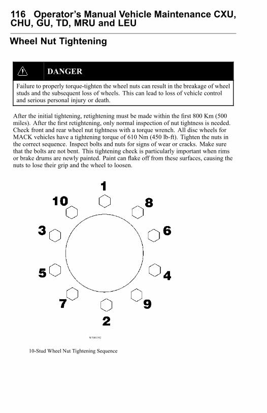
116 Operator’s Manual Vehicle Maintenance CXU,CHU, GU, TD, MRU and LEU
Wheel Nut Tightening
DANGER
Failure to properly torque-tighten the wheel nuts can result in the breakage of wheelstuds and the subsequent loss of wheels. This can lead to loss of vehicle controland serious personal injury or death.
After the initial tightening, retightening must be made within the first 800 Km (500miles). After the first retightening, only normal inspection of nut tightness is needed.Check front and rear wheel nut tightness with a torque wrench. All disc wheels forMACK vehicles have a tightening torque of 610 Nm (450 lb-ft). Tighten the nuts inthe correct sequence. Inspect bolts and nuts for signs of wear or cracks. Make surethat the bolts are not bent. This tightening check is particularly important when rimsor brake drums are newly painted. Paint can flake off from these surfaces, causing thenuts to lose their grip and the wheel to loosen.
W7001392
10-Stud Wheel Nut Tightening Sequence
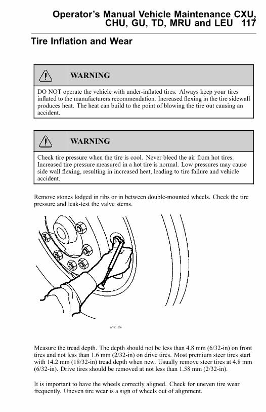
Operator’s Manual Vehicle Maintenance CXU,CHU, GU, TD, MRU and LEU 117
Tire Inflation and Wear
WARNING
DO NOT operate the vehicle with under-inflated tires. Always keep your tiresinflated to the manufacturers recommendation. Increased flexing in the tire sidewallproduces heat. The heat can build to the point of blowing the tire out causing anaccident.
WARNING
Check tire pressure when the tire is cool. Never bleed the air from hot tires.Increased tire pressure measured in a hot tire is normal. Low pressures may causeside wall flexing, resulting in increased heat, leading to tire failure and vehicleaccident.
Remove stones lodged in ribs or in between double-mounted wheels. Check the tirepressure and leak-test the valve stems.
W7001270
Measure the tread depth. The depth should not be less than 4.8 mm (6/32-in) on fronttires and not less than 1.6 mm (2/32-in) on drive tires. Most premium steer tires startwith 14.2 mm (18/32-in) tread depth when new. Usually remove steer tires at 4.8 mm(6/32-in). Drive tires should be removed at not less than 1.58 mm (2/32-in).
It is important to have the wheels correctly aligned. Check for uneven tire wearfrequently. Uneven tire wear is a sign of wheels out of alignment.

118 Operator’s Manual Vehicle Maintenance CXU,CHU, GU, TD, MRU and LEU
Tire HintsHints on How to Avoid Unnecessary TireWear
• Maintain correct tire pressure• Check the tire pressure when the tires are cold• Check that valve caps are not missing• Keep the wheels balanced• Tire wear increases with speed• Overloading not only decreases tire life but also creates a hazard• Incorrect front end alignment causes increased wear• Unnecessary tire rotation may cause excessive wear
Note: A cold weather initial driving period will increase the life of new or retreadedtires. Dual mounted wheels should always be of the same type and diameter (maximaldiameter difference allowed is 6 mm [1/4 in]).
MACK Inc. is committed to repair procedure 642 (RP 642), American TireAssociation (ATA) and The Maintenance Council (TMC).
Representatives from MACK Inc. actively participated, along with twenty-twocompanies, in developing recommended practice 642 entitled Total VehicleAlignment: Recommendations for Maximizing Tire and Alignment relatedComponent Life. Recommended Practice 642 (RP 642) is published by theMaintenance Council, American Trucking Associations, Inc.
Companies that participated in the development of RP 642 are listed in the RP.
Typical Wear Patterns
Incorrect Air Pressure
A. Air pressure too high gives rapid wear in the middle.B. Air pressure too low gives rapid shoulder wear.
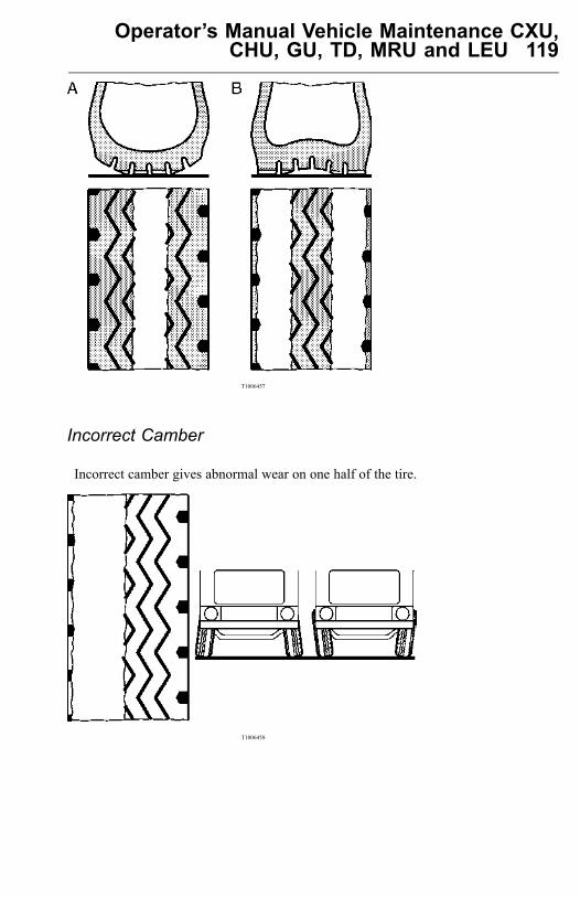
Operator’s Manual Vehicle Maintenance CXU,CHU, GU, TD, MRU and LEU 119
T1006457
Incorrect Camber
Incorrect camber gives abnormal wear on one half of the tire.
T1006458
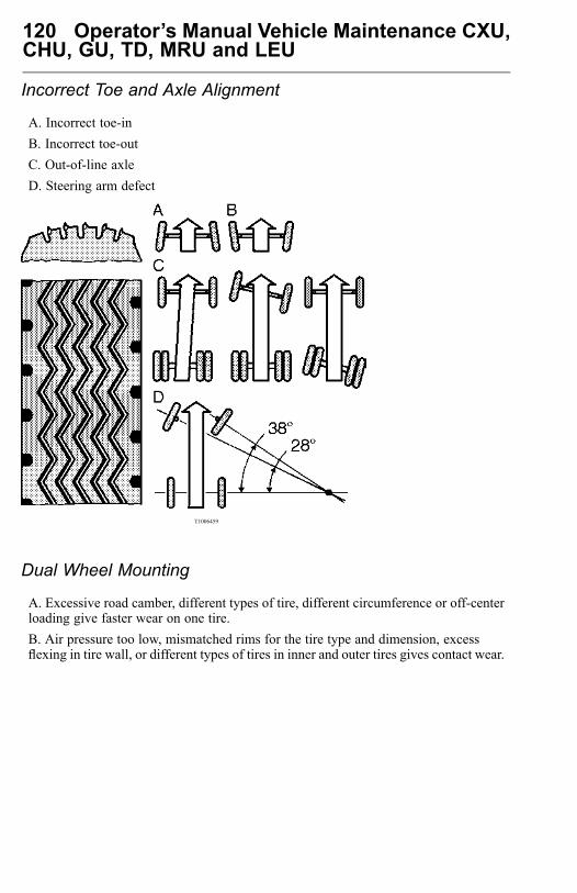
120 Operator’s Manual Vehicle Maintenance CXU,CHU, GU, TD, MRU and LEU
Incorrect Toe and Axle Alignment
A. Incorrect toe-inB. Incorrect toe-outC. Out-of-line axleD. Steering arm defect
T1006459
Dual Wheel Mounting
A. Excessive road camber, different types of tire, different circumference or off-centerloading give faster wear on one tire.B. Air pressure too low, mismatched rims for the tire type and dimension, excessflexing in tire wall, or different types of tires in inner and outer tires gives contact wear.
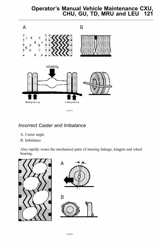
Operator’s Manual Vehicle Maintenance CXU,CHU, GU, TD, MRU and LEU 121
T1006718
Incorrect Caster and Imbalance
A. Caster angleB. Imbalance
Also rapidly wears the mechanical parts of steering linkage, kingpin and wheelbearing.
T1006460
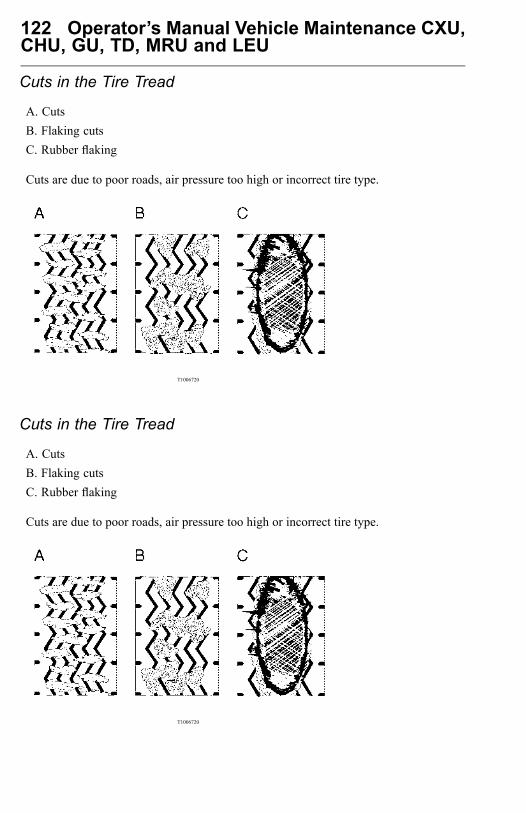
122 Operator’s Manual Vehicle Maintenance CXU,CHU, GU, TD, MRU and LEU
Cuts in the Tire Tread
A. CutsB. Flaking cutsC. Rubber flaking
Cuts are due to poor roads, air pressure too high or incorrect tire type.
T1006720
Cuts in the Tire Tread
A. CutsB. Flaking cutsC. Rubber flaking
Cuts are due to poor roads, air pressure too high or incorrect tire type.
T1006720

Operator’s Manual Vehicle Maintenance CXU,CHU, GU, TD, MRU and LEU 123
Spot Wear
Sudden braking, locking brakes or out-of-round brake drums give spot wear.
T1006721
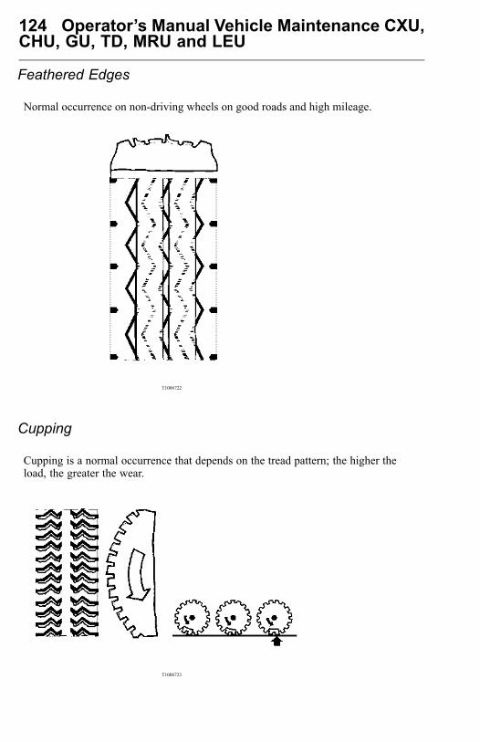
124 Operator’s Manual Vehicle Maintenance CXU,CHU, GU, TD, MRU and LEU
Feathered Edges
Normal occurrence on non-driving wheels on good roads and high mileage.
T1006722
Cupping
Cupping is a normal occurrence that depends on the tread pattern; the higher theload, the greater the wear.
T1006723
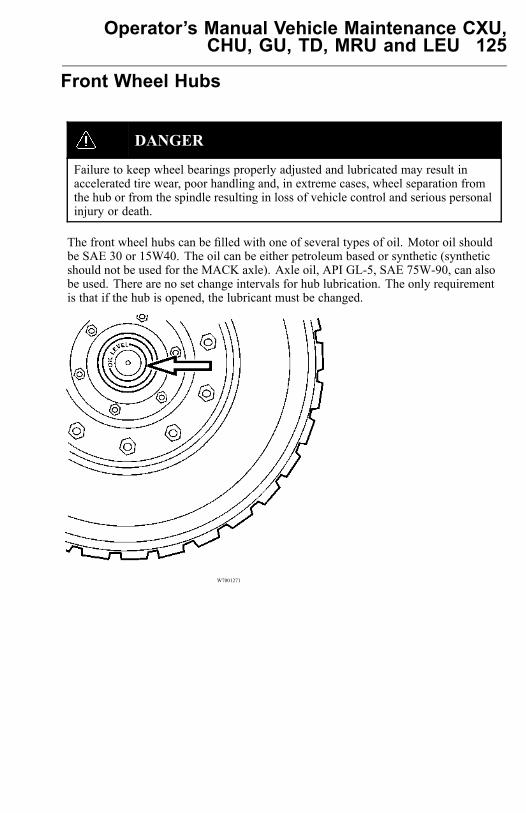
Operator’s Manual Vehicle Maintenance CXU,CHU, GU, TD, MRU and LEU 125
Front Wheel Hubs
DANGER
Failure to keep wheel bearings properly adjusted and lubricated may result inaccelerated tire wear, poor handling and, in extreme cases, wheel separation fromthe hub or from the spindle resulting in loss of vehicle control and serious personalinjury or death.
The front wheel hubs can be filled with one of several types of oil. Motor oil shouldbe SAE 30 or 15W40. The oil can be either petroleum based or synthetic (syntheticshould not be used for the MACK axle). Axle oil, API GL-5, SAE 75W-90, can alsobe used. There are no set change intervals for hub lubrication. The only requirementis that if the hub is opened, the lubricant must be changed.
W7001271
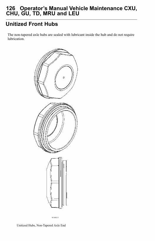
126 Operator’s Manual Vehicle Maintenance CXU,CHU, GU, TD, MRU and LEU
Unitized Front Hubs
The non-tapered axle hubs are sealed with lubricant inside the hub and do not requirelubrication.
W1000213
Unitized Hubs, Non-Tapered Axle End

Operator’s Manual Vehicle Maintenance CXU,CHU, GU, TD, MRU and LEU 127
W1000212
Tapered Axle End
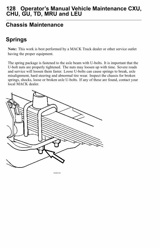
128 Operator’s Manual Vehicle Maintenance CXU,CHU, GU, TD, MRU and LEU
Chassis Maintenance
SpringsNote: This work is best performed by a MACK Truck dealer or other service outlethaving the proper equipment.
The spring package is fastened to the axle beam with U-bolts. It is important that theU-bolt nuts are properly tightened. The nuts may loosen up with time. Severe roadsand service will loosen them faster. Loose U-bolts can cause springs to break, axlemisalignment, hard steering and abnormal tire wear. Inspect the chassis for brokensprings, shocks, loose or broken axle U-bolts. If any of these are found, contact yourlocal MACK dealer.
W6001504
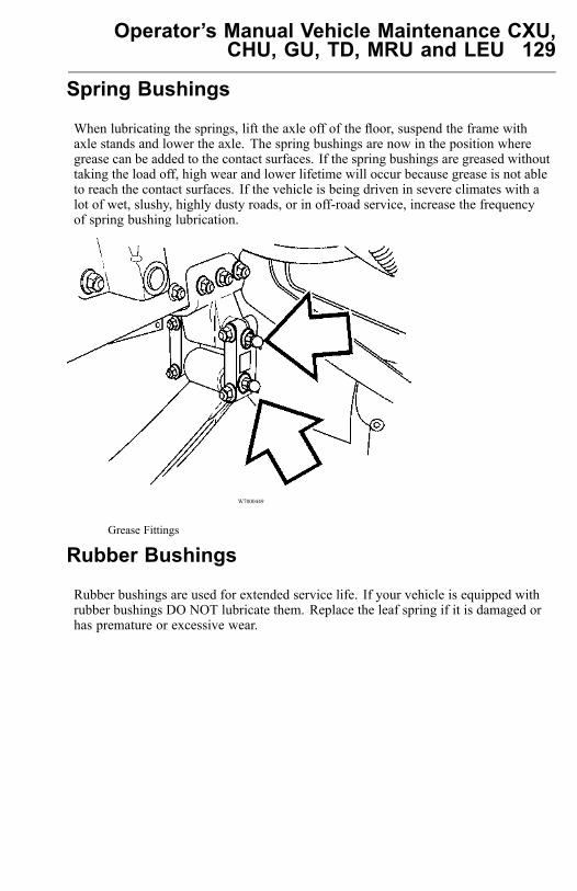
Operator’s Manual Vehicle Maintenance CXU,CHU, GU, TD, MRU and LEU 129
Spring Bushings
When lubricating the springs, lift the axle off of the floor, suspend the frame withaxle stands and lower the axle. The spring bushings are now in the position wheregrease can be added to the contact surfaces. If the spring bushings are greased withouttaking the load off, high wear and lower lifetime will occur because grease is not ableto reach the contact surfaces. If the vehicle is being driven in severe climates with alot of wet, slushy, highly dusty roads, or in off-road service, increase the frequencyof spring bushing lubrication.
W7000449
Grease Fittings
Rubber Bushings
Rubber bushings are used for extended service life. If your vehicle is equipped withrubber bushings DO NOT lubricate them. Replace the leaf spring if it is damaged orhas premature or excessive wear.

130 Operator’s Manual Vehicle Maintenance CXU,CHU, GU, TD, MRU and LEU
Cab Maintenance
Cab Air Filter
To provide comfortable and clean fresh air in the cab, the heating and air conditioningsystem is designed with a replaceable filter.
Under normal operating conditions the filter should be replaced every 6 months toensure the efficiency of the heating and air conditioning system. Failure to replacethe filter may cause damage to heater/AC components.
Dusty conditions may require more frequent replacement.
W8056454

Operator’s Manual Vehicle Maintenance CXU,CHU, GU, TD, MRU and LEU 131
Doors
The door lock mechanism should be greased annually using white grease. Lubricatethe door lock cylinder with liquid graphite annually, or more often in climates with alot of snow and salt on the roads. Coat the door stop arm with white grease annually.On wet and salted roads, road spray can enter the door lock key cylinder. Lubricatethe cylinder with liquid graphite annually or more often if necessary. The door hingepins are treated at manufacturing and then sealed. No lubrication is necessary. Tokeep the door rubber moldings and seals around the windows in good working orderand to prevent them from freezing shut during the cold season, occasionally sprayon a silicone compound.
W8003203
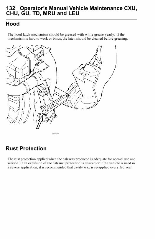
132 Operator’s Manual Vehicle Maintenance CXU,CHU, GU, TD, MRU and LEU
Hood
The hood latch mechanism should be greased with white grease yearly. If themechanism is hard to work or binds, the latch should be cleaned before greasing.
C0029317
Rust Protection
The rust protection applied when the cab was produced is adequate for normal use andservice. If an extension of the cab rust protection is desired or if the vehicle is used ina severe application, it is recommended that cavity wax is re-applied every 3rd year.

Operator’s Manual Vehicle Maintenance CXU,CHU, GU, TD, MRU and LEU 133
Paint and Brightwork Care
Cab
CAUTION
When using a pressure washer to clean the vehicle, do not direct the spray atelectrical components in the engine compartment such as the alternator, starterand compressors. Water spray from pressure washers can damage electricalcomponents.
Wash all exterior painted surfaces frequently to remove dirt. It is especially importantto wash off salt-laden snow and ice during the cold season. A mild detergent approvedfor automotive cleaning can be used but avoid strong detergents.
Note: DO NOT aim the water jet directly at door and window seals or door locks.If locks are filled with water, use compressed air to clean the water out and thenapply liquid graphite. Be especially careful of leaving water in locks or around sealsduring freezing weather.
Apply a coat of wax regularly. This will help the paint and other surfaces keep theirluster. If the surface gets dull, use a restoring cleaner specially designed for this.Clean off all tar spots and tree sap before waxing.
Chassis
Keep the chassis free from buildup of dirt. Make sure the chassis is cleaned before themaintenance inspections to help spotting leaks, etc. As salt can be part of the roadsludge during the cold season, remove buildup of snow and ice so it does not promotecorrosion. At the end of the cold season, thoroughly flush away all collected dirtfrom the chassis.
If signs of delamination of the frame rail are apparent, complete the following steps:1 Clean chassis with high pressure water spray. Use mild detergent if available;
remove loose dirt and grease.2 Continue high pressure wash to affected delamination areas of paint from the frame
rails. Apply high pressure spray until paint holds on frame substrates.
After completing these steps, to avoid further delamination, have the framerailserviced as soon as possible.
134 Operator’s Manual Vehicle Maintenance CXU,CHU, GU, TD, MRU and LEU
Stainless Steel
Stainless steel will rust if exposed to salt for too long. Wash frequently, especiallyduring the cold season, to remove salt-laden snow and ice. If rust appears, wash thesurface and use a rubbing compound to remove the rust. Apply a coat of wax as afinish (do not wax parts that get hot, such as exhaust pipes, etc.).
Note: Never use steel wool to clean stainless steel. Pieces of the steel wool break offand can create rust stains on the surface.
Chrome
Chrome surfaces will rust if they are not cleaned and protected. This is especiallyimportant during the cold season when roads are salted or in coastal areas where thesalt level in the air is high. Clean chrome surfaces with clean water. If the surface hasheavy dirt or tar spots, use a tar remover. To remove rust spots, use a non-abrasivechrome cleaner and apply a coat of wax as a finish (do not wax parts that get hot, suchas exhaust pipes, etc.).
Note: Never use steel wool to clean chrome. Pieces of the steel wool break off andcan create rust stains on the surface.
Aluminum
Unprotected aluminum surfaces will form an oxide layer if not maintained. This isespecially important during the cold season when roads are salted or in coastal areaswhere the salt level in the air is high. Clean with steam or high pressure water. Use amild detergent if the dirt is heavy. Rinse well. Clean aluminum surfaces with warmwater. If the surface has heavy dirt or tar spots, use a tar remover. To prevent spotting,wipe aluminum surfaces dry after washing.
Upholstery
Clean vinyl and cloth upholstery with light brushing or vacuuming. If heavily soiledand spots caused by oil, ice cream shoe polish, grease, etc., use a clothing fabricstain remover.
Plastic
The plastic in the upholstery can be cleaned with a soft cloth and mild soap solution.
Operator’s Manual Vehicle Maintenance CXU,CHU, GU, TD, MRU and LEU 135
Alcntera Suede-Like Material
Suede-like upholster can be cleaned with a soft cloth and mild soap solution.
Leather Care
MACK’s Leather upholstery is manufactured with a protectant to repel soiling. Overtime, sunlight, grease and dirt can break down the protection. Staining, cracking,scuffing, and fading can result.
CAUTION
DO NOT use gasoline, naphtha or similar cleaning agents on the plastic or leathersince these can cause damage. Take extra care when removing stains such as ink orlipstick since the coloring can spread. Use solvents sparingly. Too much solventcan damage the seat padding. Start from the outside of the stain and work towardthe center. Sharp objects (e.g. pencils or pens in a pocket) or Velcro fasteners onclothing may damage the textile upholstery.
136 Operator’s Manual Vehicle Maintenance CXU,CHU, GU, TD, MRU and LEU
Lubrication
Chassis Lubrication
DANGER
Before working on or servicing a vehicle, set the parking brakes, place thetransmission in neutral and chock the wheels. Failure to do so can result inunexpected vehicle movement and can cause serious personal injury or death.
General lubrication includes lubricating all the grease fittings in the drivetrain, frontand rear suspensions, power steering, and front axle, using a grease gun. Grease thechassis every 24 000 Km (15,000 miles). However, if the vehicle is in a demandingapplication or running in a dirty or corrosive atmosphere, adjust the lubricationintervals to reflect heavy-duty use. For example, if driven in heavy stop-and-go trafficwith a lot of maneuvering, the lubrication intervals should be every 16 000 Km(10,000 miles) or less. All lubricating points are found on the chassis lubricationchart on the next page.
Lubricating Grease
Use grease with a lithium base with EP additives and a consistency of NLGI No.2. Care should be taken not to use any grease other than one with EP additivesfor the driveshaft. DO NOT use any solid lubricants, such as graphite, copper ormolybdenum disulfide.
Lubrication Procedure
Make sure the grease fittings are cleaned off before greasing fill grease to the pointwhere old grease and contaminants are forced out from the part and only new greasecomes out. If new grease cannot be filled so old grease is flushed out, the part needsto be checked for problems. If a fitting does not accept lubrication due to damage orinternal stoppage, replace it with a new fitting.
Note: Think of greasing the same way as an oil change. All old grease should comeout and be replaced with new grease. Remove excess grease from fittings, shacklesand other surfaces.
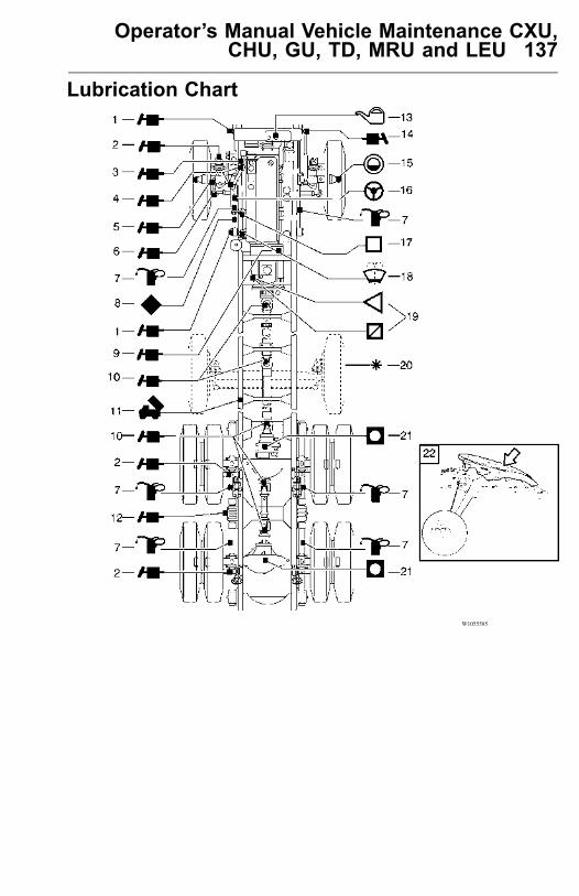
Operator’s Manual Vehicle Maintenance CXU,CHU, GU, TD, MRU and LEU 137
Lubrication Chart
W1055585
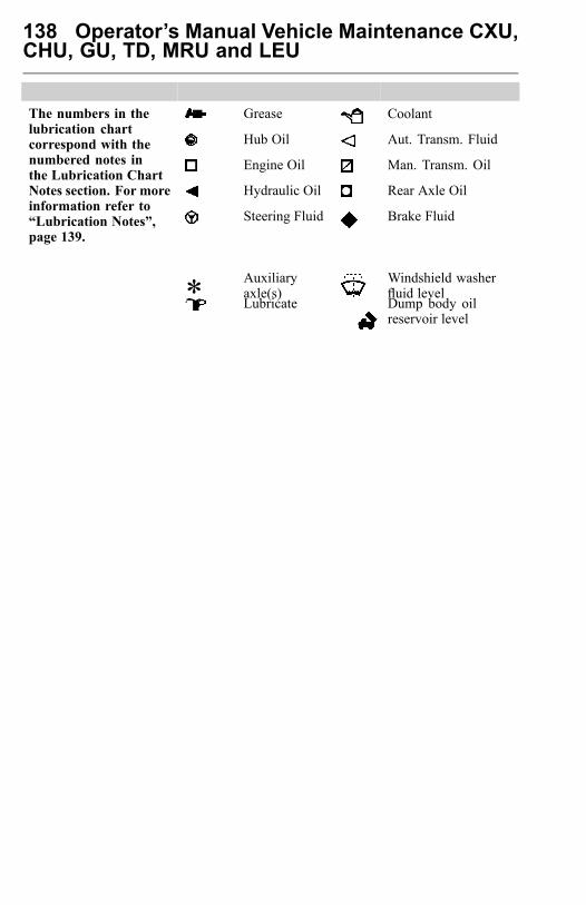
138 Operator’s Manual Vehicle Maintenance CXU,CHU, GU, TD, MRU and LEU
Grease Coolant
Hub Oil Aut. Transm. Fluid
Engine Oil Man. Transm. Oil
Hydraulic Oil Rear Axle Oil
The numbers in thelubrication chartcorrespond with thenumbered notes inthe Lubrication ChartNotes section. For moreinformation refer to“Lubrication Notes”,page 139.
Steering Fluid Brake Fluid
* Auxiliaryaxle(s)
Windshield washerfluid level
Lubricate Dump body oilreservoir level

Operator’s Manual Vehicle Maintenance CXU,CHU, GU, TD, MRU and LEU 139
Lubrication Notes1 Spring hanger: Use a lithium based
grease with specification API NLGINo. 2. When lubricating the left andright sides of the front springs, liftthe axle off of the floor, suspend theframe with axle stands and lower theaxle. The spring bushings are nowin the position where grease can beadded to the contact surfaces.Note: The rock guard will have to beremoved (if equipped).Note: Always grease a MACK frontaxle with the wheels on the ground.Note: To grease non-MACK axles,they are typically greased with thewheels on the ground. Consult withthe axle manufacturer for the latestrecommendation.
2 Slack adjuster: Do not grease till 1stscheduled maintenance interval.Note: See ManufacturesSpecifications for specific grease.Adjust according to the specific slackadjuster manufacturing specifications.
2A Brake cam:
Note: If the brake cam seal does notpurge, make sure the inner seal doesnot purge into the brake drum andonto the brake linings.
3 Steering gear: Use a lithium basedgrease with specification API NLGINo. 2. Only use a hand operatedgrease gun. The high pressure from anair operated grease gun will damagethe seal.
4 Draglink and Steering Shaft:Use a lithium based grease withspecification API NLGI No. 2.
5 Kingpin, upper and lower:Use a lithium based grease withspecification API NLGI No. 2.
Note: Always grease a MACK frontaxle with the wheels on the ground.
Note: To grease non-MACK axles,they are typically greased with thewheels on the ground. Consult withthe axle manufacturer for the latestrecommendation.
6 Tie-rod: Use a lithium based greasewith specification API NLGI No. 2.
Note: MACK axles may usea greased-for-life tie-rod. Noprovisions for adding grease areavailable.
7 Leaf Springs: Front and rear leafspring eye pins, should be pressurelubricated with chassis grease.Vehicles equipped with multi leafsprings should also have, the leaveslubricated with a spray gun or brushusing a rust inhibiting oil.
CAUTION
Keep grease and oil, off of rubberbushings. Failure to do so will result incomponent damage.
Note: If the vehicle is operated insandy or dusty environments, thespring ends should be left dry. Dirtand grease can mix, resulting in a"sandpaper" action that may causepre-mature wear to the spring ends.
8 Brake fluid and clutch reservoir:Check the fluid level in the reservoir.Add brake fluid if necessary. Useonly DOT 4 brake fluid in the clutchrelease system. Mixing DOT 4 brakefluid with petroleum based oil willcause seal damage which will causeleakage.
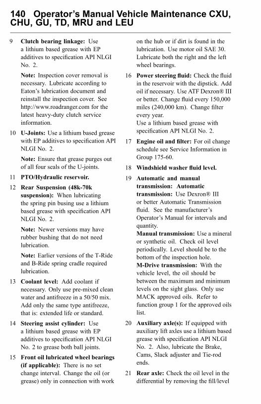
140 Operator’s Manual Vehicle Maintenance CXU,CHU, GU, TD, MRU and LEU
9 Clutch bearing linkage: Usea lithium based grease with EPadditives to specification API NLGINo. 2.
Note: Inspection cover removal isnecessary. Lubricate according toEaton’s lubrication document andreinstall the inspection cover. Seehttp://www.roadranger.com for thelatest heavy-duty clutch serviceinformation.
10 U-Joints: Use a lithium based greasewith EP additives to specification APINLGI No. 2.
Note: Ensure that grease purges outof all four seals of the U-joints.
11 PTO/Hydraulic reservoir.
12 Rear Suspension (48k-70ksuspension): When lubricatingthe spring pin busing use a lithiumbased grease with specification APINLGI No. 2.
Note: Newer versions may haverubber bushing that do not needlubrication.
Note: Earlier versions of the T-Rideand B-Ride spring cradle requiredlubrication.
13 Coolant level: Add coolant ifnecessary. Only use pre-mixed cleanwater and antifreeze in a 50/50 mix.Add only the same type antifreeze,that is: extended life or standard.
14 Steering assist cylinder: Usea lithium based grease with EPadditives to specification API NLGINo. 2 to grease both ball joints.
15 Front oil lubricated wheel bearings(if applicable): There is no setchange interval. Change the oil (orgrease) only in connection with work
on the hub or if dirt is found in thelubrication. Use motor oil SAE 30.Lubricate both the right and the leftwheel bearings.
16 Power steering fluid: Check the fluidin the reservoir with the dipstick. Addoil if necessary. Use ATF Dexron® IIIor better. Change fluid every 150,000miles (240,000 km). Change filterevery year.Use a lithium based grease withspecification API NLGI No. 2.
17 Engine oil and filter: For oil changeschedule see Service Information inGroup 175-60.
18 Windshield washer fluid level.
19 Automatic and manualtransmission: Automatictransmission: Use Dexron® IIIor better Automatic Transmissionfluid. See the manufacturer’sOperator’s Manual for intervals andquantity.Manual transmission: Use a mineralor synthetic oil. Check oil levelperiodically. Level should be to thebottom of the inspection hole.M-Drive transmission: With thevehicle level, the oil should bebetween the maximum and minimumlevels on the sight glass. Only useMACK approved oils. Refer tofunction group 1 for the approved oilslist.
20 Auxiliary axle(s): If equipped withauxiliary lift axles use a lithium basedgrease with specification API NLGINo. 2. Also, lubricate the Brake,Cams, Slack adjuster and Tie-rodends.
21 Rear axle: Check the oil level in thedifferential by removing the fill/level
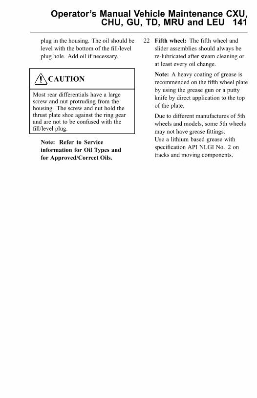
Operator’s Manual Vehicle Maintenance CXU,CHU, GU, TD, MRU and LEU 141
plug in the housing. The oil should belevel with the bottom of the fill/levelplug hole. Add oil if necessary.
CAUTION
Most rear differentials have a largescrew and nut protruding from thehousing. The screw and nut hold thethrust plate shoe against the ring gearand are not to be confused with thefill/level plug.
Note: Refer to Serviceinformation for Oil Types andfor Approved/Correct Oils.
22 Fifth wheel: The fifth wheel andslider assemblies should always bere-lubricated after steam cleaning orat least every oil change.
Note: A heavy coating of grease isrecommended on the fifth wheel plateby using the grease gun or a puttyknife by direct application to the topof the plate.
Due to different manufactures of 5thwheels and models, some 5th wheelsmay not have grease fittings.Use a lithium based grease withspecification API NLGI No. 2 ontracks and moving components.
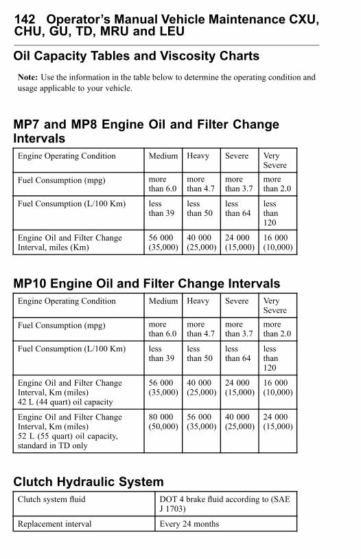
142 Operator’s Manual Vehicle Maintenance CXU,CHU, GU, TD, MRU and LEU
Oil Capacity Tables and Viscosity ChartsNote: Use the information in the table below to determine the operating condition andusage applicable to your vehicle.
MP7 and MP8 Engine Oil and Filter ChangeIntervalsEngine Operating Condition Medium Heavy Severe Very
Severe
Fuel Consumption (mpg) morethan 6.0
morethan 4.7
morethan 3.7
morethan 2.0
Fuel Consumption (L/100 Km) lessthan 39
lessthan 50
lessthan 64
lessthan120
Engine Oil and Filter ChangeInterval, miles (Km)
56 000(35,000)
40 000(25,000)
24 000(15,000)
16 000(10,000)
MP10 Engine Oil and Filter Change IntervalsEngine Operating Condition Medium Heavy Severe Very
Severe
Fuel Consumption (mpg) morethan 6.0
morethan 4.7
morethan 3.7
morethan 2.0
Fuel Consumption (L/100 Km) lessthan 39
lessthan 50
lessthan 64
lessthan120
Engine Oil and Filter ChangeInterval, Km (miles)42 L (44 quart) oil capacity
56 000(35,000)
40 000(25,000)
24 000(15,000)
16 000(10,000)
Engine Oil and Filter ChangeInterval, Km (miles)52 L (55 quart) oil capacity,standard in TD only
80 000(50,000)
56 000(35,000)
40 000(25,000)
24 000(15,000)
Clutch Hydraulic SystemClutch system fluid DOT 4 brake fluid according to (SAE
J 1703)
Replacement interval Every 24 months
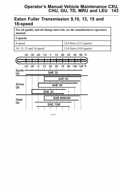
Operator’s Manual Vehicle Maintenance CXU,CHU, GU, TD, MRU and LEU 143
Eaton Fuller Transmission 9,10, 13, 15 and18-speedFor oil quality and oil change intervals, see the manufacturers operatorsmanual.
Capacity
9-speed 12.0 liters (13.5 quarts)
10, 13, 15 and 18-speed 13.0 liters (14.0 quarts)
W1000179
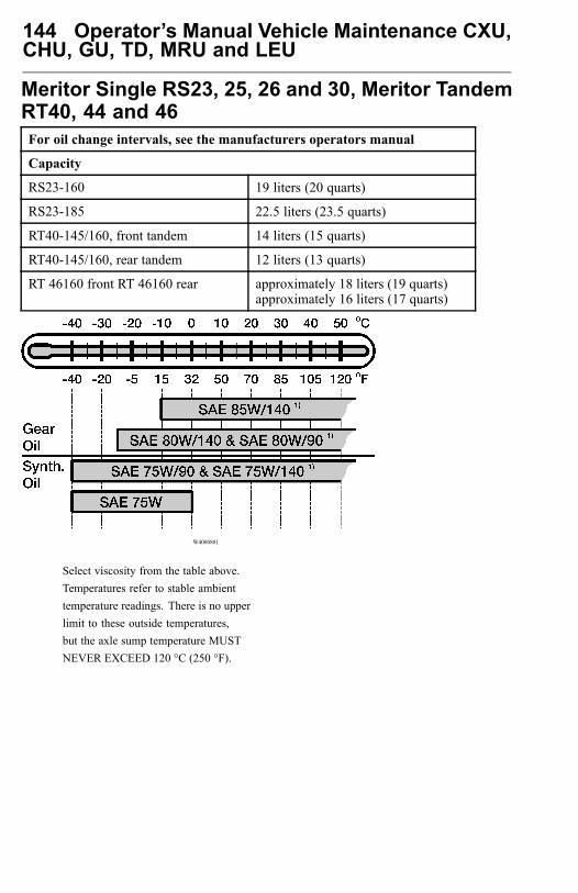
144 Operator’s Manual Vehicle Maintenance CXU,CHU, GU, TD, MRU and LEU
Meritor Single RS23, 25, 26 and 30, Meritor TandemRT40, 44 and 46For oil change intervals, see the manufacturers operators manual
Capacity
RS23-160 19 liters (20 quarts)
RS23-185 22.5 liters (23.5 quarts)
RT40-145/160, front tandem 14 liters (15 quarts)
RT40-145/160, rear tandem 12 liters (13 quarts)
RT 46160 front RT 46160 rear approximately 18 liters (19 quarts)approximately 16 liters (17 quarts)
W4000881
Select viscosity from the table above.Temperatures refer to stable ambienttemperature readings. There is no upperlimit to these outside temperatures,but the axle sump temperature MUSTNEVER EXCEED 120 °C (250 °F).
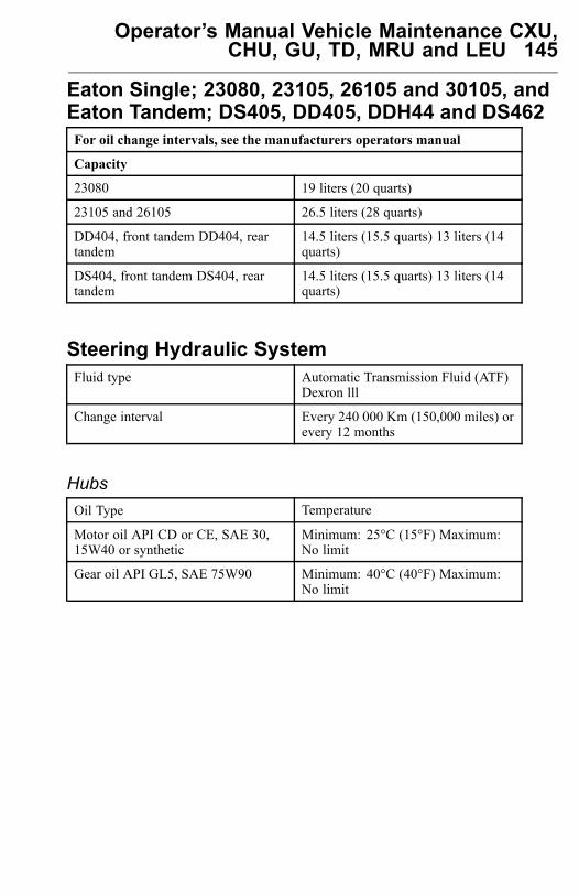
Operator’s Manual Vehicle Maintenance CXU,CHU, GU, TD, MRU and LEU 145
Eaton Single; 23080, 23105, 26105 and 30105, andEaton Tandem; DS405, DD405, DDH44 and DS462For oil change intervals, see the manufacturers operators manual
Capacity
23080 19 liters (20 quarts)
23105 and 26105 26.5 liters (28 quarts)
DD404, front tandem DD404, reartandem
14.5 liters (15.5 quarts) 13 liters (14quarts)
DS404, front tandem DS404, reartandem
14.5 liters (15.5 quarts) 13 liters (14quarts)
Steering Hydraulic SystemFluid type Automatic Transmission Fluid (ATF)
Dexron lll
Change interval Every 240 000 Km (150,000 miles) orevery 12 months
HubsOil Type Temperature
Motor oil API CD or CE, SAE 30,15W40 or synthetic
Minimum: 25°C (15°F) Maximum:No limit
Gear oil API GL5, SAE 75W90 Minimum: 40°C (40°F) Maximum:No limit
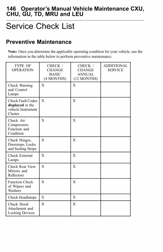
146 Operator’s Manual Vehicle Maintenance CXU,CHU, GU, TD, MRU and LEU
Service Check List
Preventive MaintenanceNote: Once you determine the applicable operating condition for your vehicle, use theinformation in the table below to perform preventive maintenance.
TYPE OFOPERATION
CHECK /CHANGEBASIC
(4 MONTHS)
CHECK /CHANGEANNUAL
(12 MONTHS)
ADDITIONALSERVICE
Check Warningand ControlLamps
X X
Check Fault Codesdisplayed in thevehicle InstrumentCluster
X X
Check AirCompressorsFunction andCondition
X X
Check Hinges,Doorstops, Locksand Sealing Strips
X X
Check ExternalLamps
X X
Check Rear ViewMirrors andReflectors
X X
Function Checkof Wipers andWashers
X X
Check Headlamps X X
Check HoodAttachment andLocking Devices
X X
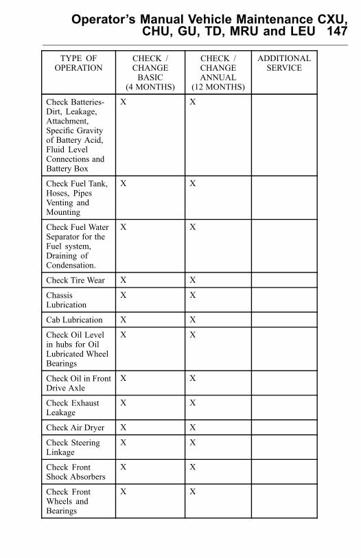
Operator’s Manual Vehicle Maintenance CXU,CHU, GU, TD, MRU and LEU 147
TYPE OFOPERATION
CHECK /CHANGEBASIC
(4 MONTHS)
CHECK /CHANGEANNUAL
(12 MONTHS)
ADDITIONALSERVICE
Check Batteries-Dirt, Leakage,Attachment,Specific Gravityof Battery Acid,Fluid LevelConnections andBattery Box
X X
Check Fuel Tank,Hoses, PipesVenting andMounting
X X
Check Fuel WaterSeparator for theFuel system,Draining ofCondensation.
X X
Check Tire Wear X X
ChassisLubrication
X X
Cab Lubrication X X
Check Oil Levelin hubs for OilLubricated WheelBearings
X X
Check Oil in FrontDrive Axle
X X
Check ExhaustLeakage
X X
Check Air Dryer X X
Check SteeringLinkage
X X
Check FrontShock Absorbers
X X
Check FrontWheels andBearings
X X
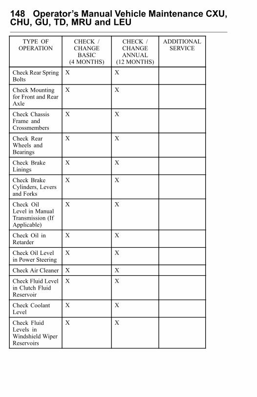
148 Operator’s Manual Vehicle Maintenance CXU,CHU, GU, TD, MRU and LEU
TYPE OFOPERATION
CHECK /CHANGEBASIC
(4 MONTHS)
CHECK /CHANGEANNUAL
(12 MONTHS)
ADDITIONALSERVICE
Check Rear SpringBolts
X X
Check Mountingfor Front and RearAxle
X X
Check ChassisFrame andCrossmembers
X X
Check RearWheels andBearings
X X
Check BrakeLinings
X X
Check BrakeCylinders, Leversand Forks
X X
Check OilLevel in ManualTransmission (IfApplicable)
X X
Check Oil inRetarder
X X
Check Oil Levelin Power Steering
X X
Check Air Cleaner X X
Check Fluid Levelin Clutch FluidReservoir
X X
Check CoolantLevel
X X
Check FluidLevels inWindshield WiperReservoirs
X X

Operator’s Manual Vehicle Maintenance CXU,CHU, GU, TD, MRU and LEU 149
TYPE OFOPERATION
CHECK /CHANGEBASIC
(4 MONTHS)
CHECK /CHANGEANNUAL
(12 MONTHS)
ADDITIONALSERVICE
CheckTransmission OilCooler hoses andConnections forleaks
X X
Valve Adjustment X REQUIRED:Once a year,every 209 000Km, (130,000miles) or every2,500 hours,(whichevercomes first)
Check Drive Belts X X
Check RadiatorFan, BearingTolerance, BoltUnions, Fan Coverand Fan Ring withRubber Seal
X X
CheckTurbocharger
X X
Check DischargeLines and Hoses
X X
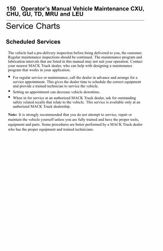
150 Operator’s Manual Vehicle Maintenance CXU,CHU, GU, TD, MRU and LEU
Service Charts
Scheduled Services
The vehicle had a pre-delivery inspection before being delivered to you, the customer.Regular maintenance inspections should be continued. The maintenance program andlubrication intervals that are listed in this manual may not suit your operation. Contactyour nearest MACK Truck dealer, who can help with designing a maintenanceprogram that works in your application.
• For regular service or maintenance, call the dealer in advance and arrange for aservice appointment. This gives the dealer time to schedule the correct equipmentand provide a trained technician to service the vehicle.
• Setting an appointment can decrease vehicle downtime.• When in for service at an authorized MACK Truck dealer, ask for outstanding
safety related recalls that relate to the vehicle. This service is available only at anauthorized MACK Truck dealership.
Note: It is strongly recommended that you do not attempt to service, repair ormaintain the vehicle yourself unless you are fully trained and have the proper tools,equipment and parts. Some procedures are better performed by a MACK Truck dealerwho has the proper equipment and trained technicians.
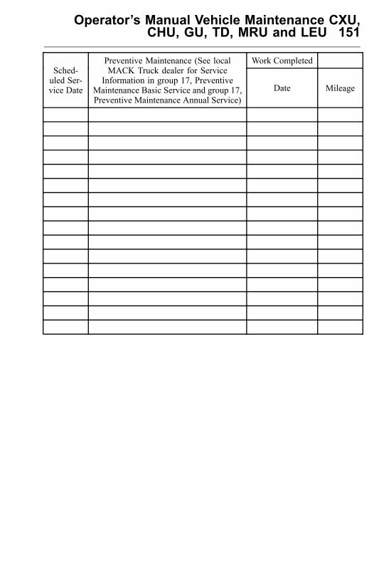
Operator’s Manual Vehicle Maintenance CXU,CHU, GU, TD, MRU and LEU 151
Work CompletedSched-uled Ser-vice Date
Preventive Maintenance (See localMACK Truck dealer for Service
Information in group 17, PreventiveMaintenance Basic Service and group 17,Preventive Maintenance Annual Service)
Date Mileage
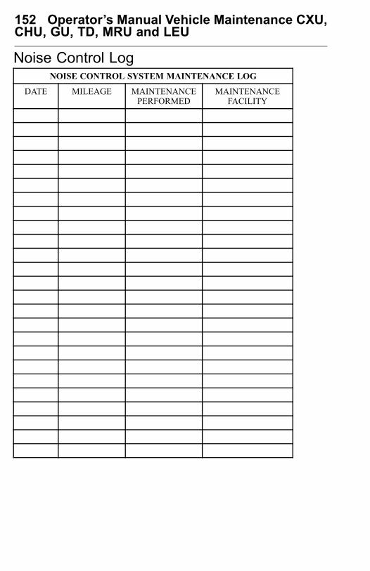
152 Operator’s Manual Vehicle Maintenance CXU,CHU, GU, TD, MRU and LEU
Noise Control LogNOISE CONTROL SYSTEM MAINTENANCE LOG
DATE MILEAGE MAINTENANCEPERFORMED
MAINTENANCEFACILITY
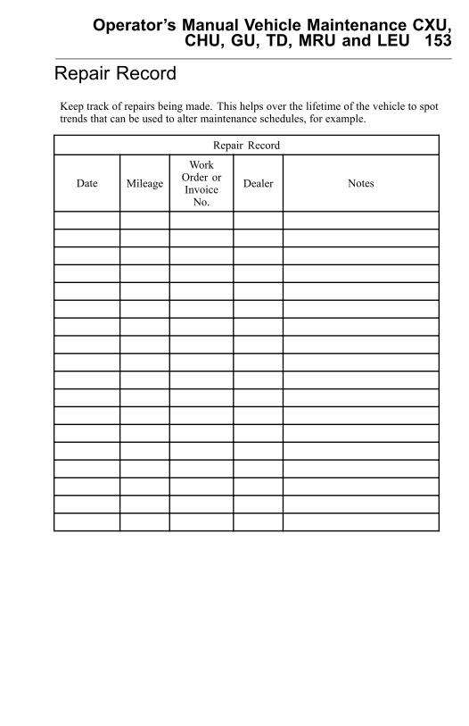
Operator’s Manual Vehicle Maintenance CXU,CHU, GU, TD, MRU and LEU 153
Repair RecordKeep track of repairs being made. This helps over the lifetime of the vehicle to spottrends that can be used to alter maintenance schedules, for example.
Repair Record
Date Mileage
WorkOrder orInvoiceNo.
Dealer Notes
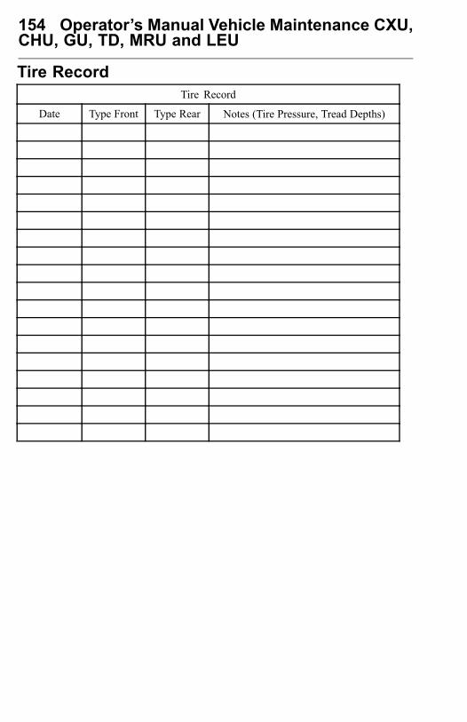
154 Operator’s Manual Vehicle Maintenance CXU,CHU, GU, TD, MRU and LEU
Tire RecordTire Record
Date Type Front Type Rear Notes (Tire Pressure, Tread Depths)
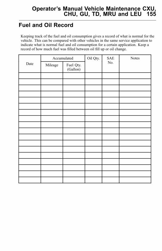
Operator’s Manual Vehicle Maintenance CXU,CHU, GU, TD, MRU and LEU 155
Fuel and Oil Record
Keeping track of the fuel and oil consumption gives a record of what is normal for thevehicle. This can be compared with other vehicles in the same service application toindicate what is normal fuel and oil consumption for a certain application. Keep arecord of how much fuel was filled between oil fill up or oil change.
AccumulatedDate Mileage Fuel Qty.
(Gallon)
Oil Qty. SAENo.
Notes
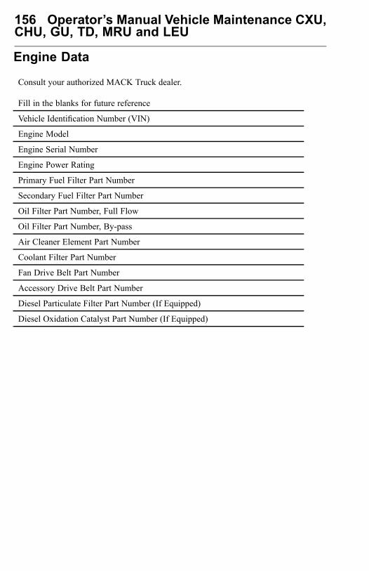
156 Operator’s Manual Vehicle Maintenance CXU,CHU, GU, TD, MRU and LEU
Engine Data
Consult your authorized MACK Truck dealer.
Fill in the blanks for future reference
Vehicle Identification Number (VIN)
Engine Model
Engine Serial Number
Engine Power Rating
Primary Fuel Filter Part Number
Secondary Fuel Filter Part Number
Oil Filter Part Number, Full Flow
Oil Filter Part Number, By-pass
Air Cleaner Element Part Number
Coolant Filter Part Number
Fan Drive Belt Part Number
Accessory Drive Belt Part Number
Diesel Particulate Filter Part Number (If Equipped)
Diesel Oxidation Catalyst Part Number (If Equipped)
Operator’s Manual Vehicle Maintenance CXU,CHU, GU, TD, MRU and LEU 157
Literature
Service Assistance and Manuals
Your MACK Truck dealer is trained and equipped to perform expert service on yourMACK vehicle. Your dealer has direct access to MACK Inc. for technical help, partsor service information.
MACK Action Service (VAS), provides on-call assistance. For help, contact VASdirectly: 24 hours a day at 1 (800) 528-6586 or 1 (800) 52-MACK. Also on theinternet: www.vas.MACK.com.
VAS offers:
1 Delivery Assurance If you need roadside assistance, VAS can arrange for loadforwarding or equipment rental.
2 Personal Assurance Trained staff for handling any vehicle problems.3 Uptime Assurance VAS will locate the nearest service provider and guarantee
payment so you can get on the road as soon as possible.4 Price Assurance VAS audits service and parts billing to ensure guaranteed labor
rates and preferred parts pricing for MACK components.
To order a single service manual or a service manual set for your vehicle, contactyour authorized MACK Truck dealer.
In order to process the request correctly, please give the model, year and VIN (lastsix digits of VIN). For VIN location, refer to “Vehicle Identification Number Label”,page 12.
158 Operator’s Manual Vehicle Maintenance CXU,CHU, GU, TD, MRU and LEU
CUSTOMER SERVICE
Call 1-800-866-1177 for MACK One-Call™The One-Call customer support system is a toll-free nationwide hotline thatoperates 24 hours a day, seven days a week, including holidays. If you breakdown on the road, simply call 1-800-866-1177. There is a staff of trained,experienced technicians ready to help. They can help troubleshoot a problemto get you back on the road, arrange to send roadside assistance or arrangefor towing to the nearest MACK dealership.
One-Call provides personalized service. The person who initially takes yourcall will be the same person who sees that your situation is resolved quicklyand to your satisfaction. If a follow-up call is necessary, the same familiarvoice will be on the other end of the line.
One-Call technicians can also help you plan ahead to keep your runningefficiently by scheduling routine maintenance and lubrication service, or bylocating the nearest MACK dealership.
Questions and ComplaintsYour satisfaction is our most important concern.
If questions or complaints arise, first discuss the matter with the servicemanager at the MACK facility involved. If you are not satisfied with theservice manager’s response, contact the branch manager, principal or generalmanager of the distributorship. If assistance is required at a service dealer,contact the owner of the establishment.
If, for any reason, you need further assistance after dealing with the personnelat a MACK subsidiary or distributor, contact the regional service manager atthe nearest MACK regional service office. The regional service manager hasthe responsibility and the authority to recommend action in most cases and(with the aid of relevant district service personnel) will make every effort toconduct a fair review of the situation.
Operator’s Manual Vehicle Maintenance CXU,CHU, GU, TD, MRU and LEU 159
AddressesThe addresses, telephone and fax numbers of the MACK Trucks, Inc. regionaloffices are:
United States
Northeast Region – 7900 National Service Road., Mail: P.O. Box 26259,Greensboro NC 27402 , TEL: (336) 291-9001
Southeast Region – 6768 Southlake Parkway, Morrow, GA 30260, TEL:(770) 960-0511, FAX: (770) 960-0593
Central Region –900 S. Frontage Rd., Suite 100, Woodridge, IL 60517, TEL:(630) 910-3330, FAX: (630) 910-3331
Southwestern and Western Regions – 5605 N. MacArthur Blvd., #550,Mail: P.O. Box 165408, Irving, TX 75016-5408, TEL: (972) 518-1614, FAX:(972) 550-0389
Canada
Executive Office –MACK Canada, Inc., 5600A Cancross Court, Mississauga,ON L5R 3E9, TEL: (905) 366-3400, FAX: (905) 366-0165
Australia
MACK Trucks Australia Pty. Ltd., CNR Archerfield and Boundary Roads,Mail: P.O. Box 364, Richlands, QLD 4077, Australia, TEL: 61-7-3853-3333,FAX: 61-7-3853-3392
International
7900 National Service Road., Mail: P.O. Box 26259, Greensboro NC 27402 ,TEL: (336) 291-9001
160 Operator’s Manual Vehicle Maintenance CXU,CHU, GU, TD, MRU and LEU
Additional AssistanceIf additional assistance is required, MACK Trucks, Inc. maintains a CustomerService Department (staffed by experienced personnel) to aid customers whoneed information or assistance not provided at the local or regional level.
The Customer Service Department phone number is (610) 709-3961.
When contacting the regional service offices or Customer Service Department,provide the following information:
• Vehicle Identification Number (VIN) — This 17-digit number is typically locatedon a label on the driver-side door latch post and behind the front axle on theright, front frame rail.
• Model and year of the vehicle• Date that the vehicle was purchased and put into service• Date(s) and mileage of repair(s)• Dealer that sold and/or serviced the vehicle• Description of unresolved service complaint or inquiry• Summary of action taken to date (by the dealer and the regional service office)• Names of individuals (if known) contacted at the dealer and the MACK Trucks,
Inc. regional service office.

161 Operator’s Manual Vehicle Maintenance CXU,CHU, GU, TD, MRU and LEU


Last page
Mack Trucks, Inc.http://www.macktrucks.com
PV776-21394653 English 04.2010© Mack Trucks, Inc., 2010