Embed Size (px)
Citation preview
Owner/Operator Manual
Models
932400 - 520
Snow Thrower
03244400C 8/01Supercedes 03244400,A,B
Printed in USA
ENGLISH
FRANÇAIS
ESPAÑOL
Transfer model & serial number label from product registration here.
Coller l’autocollant du modèle et du numéro de série dans cet encadré.
Transferir aquí la etiqueta del modelo y número de serie del registro del producto.
2
ENGLISH
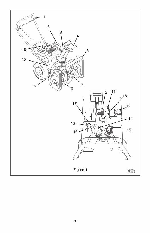
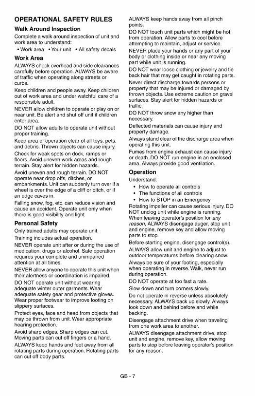
1. Attachment Clutch Bail2. Spark Plug and Wire3. Chute Control Lever4. Chute Deflector5. Discharge Chute6. Housing 7. Scraper Blade8. Impeller9. Auger
10. Belt Cover11. Oil Fill and Dipstick12. Fuel Tank and Cap13. Choke14. Primer Bulb15. Recoil Start16. Ignition Switch17. Throttle18. Electric Starter
FRANÇAIS
1. Commande d’embrayage de l’outil
2. Bougie et fil3. Levier de commande
de la goulotte 4. Déflecteur de la goulotte5. Goulotte d’évacuation6. Carter7. Lame racleuse8. Turbine9. Rotor
10. Couvercle de la courroie11. Tube de remplissage
en huile et jauge12. Réservoir de carburant et
bouchon13. Starter14. Poire d’amorçage15. Lanceur à rappel16. Clé de contact17. Commande des gaz18. Démarreur électrique
ESPAÑOL
1. Asa del embrague del accesorio
2. Bujía y cable3. Palanca de control
de la tolva 4. Deflector de la tolva5. Tolva de descarga6. Alojamiento7. Cuchilla raspadora8. Propulsor9. Sinfín
10. Cubierta de la correa11. Llenado de aceite y
varilla medidora12. Depósito del combustible
y tapón13. Estrangulador14. Perilla de cebado15. Arranque de retroceso16. Llave de encendido17. Acelerador18. Arranque eléctrico
CONTROLS AND FEATURES
The engine exhaust from this productcontains chemicals known to the State
of California to cause cancer, birthdefects or other reproductive harm.
WARNING
3
1
2
3
45
6
789
10
11
12
1314
1516
17
OS2085OS1915
Figure 1
18
18
GB - 4
Controls and Features . . . . . . . . . . . . . . . . 2
Safety . . . . . . . . . . . . . . . . . . . . . . . . . . . . . . 5
Assembly . . . . . . . . . . . . . . . . . . . . . . . . . . . 9
Operation. . . . . . . . . . . . . . . . . . . . . . . . . . 10
Maintenance . . . . . . . . . . . . . . . . . . . . . . . 12
Service & Adjustments. . . . . . . . . . . . . . . 14
Storage. . . . . . . . . . . . . . . . . . . . . . . . . . . . 18
Troubleshooting . . . . . . . . . . . . . . . . . . . . 18
Accessories . . . . . . . . . . . . . . . . . . . . . . . . 18
Service Parts . . . . . . . . . . . . . . . . . . . . . . . 19
Specifications . . . . . . . . . . . . . . . . . . . . . . 19
Warranty. . . . . . . . . . . . . . . . . . . . . . . . . . . 20
Mack, Mack and the Bulldog design oval logo, the Bulldog design, and Built Like a Mack Truck are Trademarks of Mack Trucks, Inc. and are used under license by Ariens Company.
THE MANUAL
Before operation of unit, carefully and completely read your manuals. The contents will provide you with an understanding of safety instructions and controls during normal operation and maintenance.All reference to left, right, front, or rear are given from operator standing in operation position and facing the direction of forward travel.
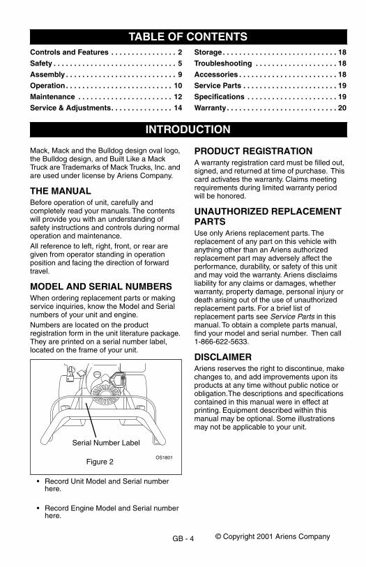
MODEL AND SERIAL NUMBERS
When ordering replacement parts or making service inquiries, know the Model and Serial numbers of your unit and engine.Numbers are located on the product registration form in the unit literature package. They are printed on a serial number label, located on the frame of your unit.
• Record Unit Model and Serial number here.
• Record Engine Model and Serial number here.
PRODUCT REGISTRATION
A warranty registration card must be filled out, signed, and returned at time of purchase. This card activates the warranty. Claims meeting requirements during limited warranty period will be honored.
UNAUTHORIZED REPLACEMENT PARTS
Use only Ariens replacement parts. The replacement of any part on this vehicle with anything other than an Ariens authorized replacement part may adversely affect the performance, durability, or safety of this unit and may void the warranty. Ariens disclaims liability for any claims or damages, whether warranty, property damage, personal injury or death arising out of the use of unauthorized replacement parts. For a brief list of replacement parts see
Service Parts
in this manual. To obtain a complete parts manual, find your model and serial number. Then call 1-866-622-5633.
DISCLAIMER
Ariens reserves the right to discontinue, make changes to, and add improvements upon its products at any time without public notice or obligation.The descriptions and specifications contained in this manual were in effect at printing. Equipment described within this manual may be optional. Some illustrations may not be applicable to your unit.
TABLE OF CONTENTS
INTRODUCTION
Serial Number Label
OS1801Figure 2
© Copyright 2001 Ariens Company
GB - 5
DELIVERY
Customer Note:
If you have purchased this product without complete assembly and instruction by your retailer, it is your responsibility to:
1. Read and understand all assembly instructions in this manual. If you do not understand or have difficulty following the instructions, contact your nearest Ariens Dealer for assistance. Make sure all assembly has been properly completed.
NOTE:
To locate your nearest Ariens Dealer, call 1-866-622-5633.
2. Understand all Safety Precautions provided in the manuals.
3. Review control functions and operation of the unit. Do not operate the snow thrower unless all controls function as described in this manual.
4. Review recommended lubrication, maintenance and adjustments.
5. Review Limited Warranty Policy.6. Fill out Original Purchaser Registration
Card and return the card to Ariens Company.
SAFETY ALERTS
Look for these symbols to point out important safety precautions. They mean:
Attention!
Personal Safety Is Involved!
Become Alert!
Obey The Message!
The safety alert symbols above and signal words below are used on decals and in this manual.Read and understand all safety messages.
NOTATIONS
NOTE:
General reference information for proper operation and maintenance practices.
IMPORTANT:
Specific procedures or information required to prevent damage to unit or attachment.
PRACTICES AND LAWS
Practice usual and customary safe working precautions, for the benefit of yourself and others. Understand and follow all safety messages. Be alert to unsafe conditions and the possibility of minor, moderate, or serious injury or death. Learn applicable rules and laws in your area.
REQUIRED OPERATOR TRAINING
Original purchaser of this unit was instructed by the seller on safe and proper operation. If unit is to be used by someone other than original purchaser; loaned, rented or sold, ALWAYS provide this manual and any needed safety training before operation.
WARNING:
Improper assembly or adjustments can cause serious injury.
SAFETY
DANGER:
IMMINENTLY HAZARDOUS SITUATION! If not avoided, WILL RESULT in death or serious injury.
WARNING:
POTENTIALLY HAZARDOUS SITUATION! If not avoided, COULD RESULT in death or serious injury.
CAUTION:
POTENTIALLY HAZARDOUS SITUATION! If not avoided, MAY RESULT in minor or moderate injury. It may also be used to alert against unsafe practices.
GB - 6
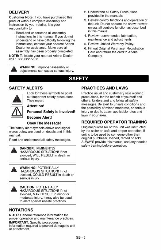
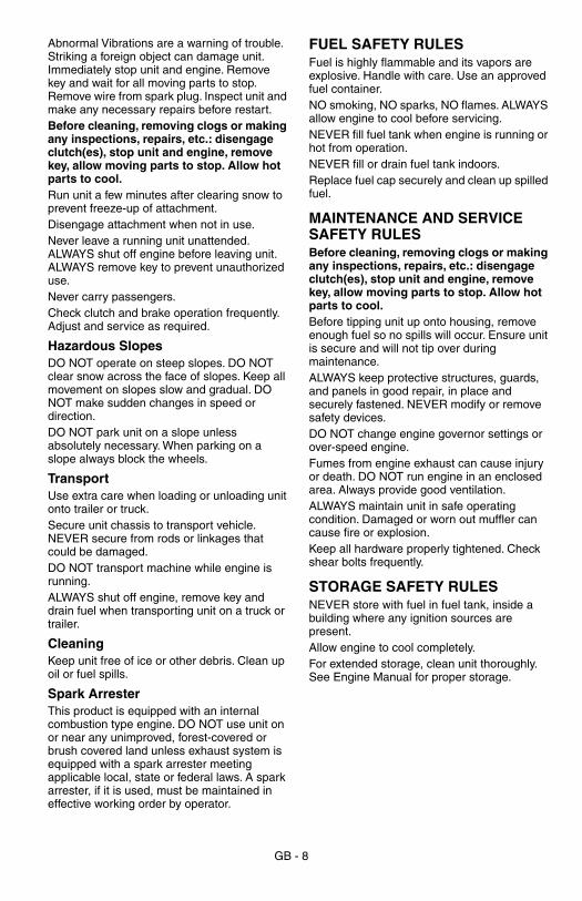
SAFETY DECALS AND LOCATIONS
ALWAYS replace missing or damaged Safety Decals. Refer to figure below for Safety Decal locations.
1. DANGER!
2. DANGER!
SAFETY
3. HOT SURFACES!
ASSEMBLY SAFETY RULES
Read, understand, and follow all safety practices in Owner/Operator Manual before assembling. Failure to follow instructions could result in personal injury and/or damage to unit.ALWAYS remove key and/or wire from spark plug before assembly. Unintentional engine start up can cause death or serious injury.
DANGER / PELIGROROTATING PARTSStop engine & remove ignition keybefore clearing.
PIECES EN ROTATIONArreter le moteur et retirer la clé decontact avant le débourrage.
PIEZAS GIRATORIASDetener el motor y sacar la llaveantes de despejar.
08093900
DANGER / PELIGROROTATING PARTSKeep clear of auger while engineis running.
PIECES EN ROTATIONNe pas s’approcher du rotorlorsque le moteur est en marche.
PIEZAS GIRATORIASMantenerse alejado del sinfínmientras que el motor esté enmarcha.
SAFETY• Lire le manuel du
l’opérateur.
• Seuls les adultes ayantrecu la formationappropriée peuventutiliser la machine,jamais les enfants.
• Toujours arrêter lemoteur et retirer la clé decontact avant de quitterle siège de l'opérateur.
• Les commandes,protections et dispositifsde sécurité doiventtoujours êtrecorrectement entretenuset en bon état defonctionnement.
• Ne jamais orienter lagoulotte d'évacuationvers des personnes pouréviter tout risque deblessure par des objetsprojetés ou vers desbâtiments pour éviter deles endommager.
SÉCURITÉ• Leer el manual del
operador.
• Permitir la operaciónsólo por adultosentrenados, nuncaniños.
• Parar el motor y sacar lallave de la ignición antesde dejar el puesto deloperador por cualquiermotivo.
• Mantener todos loscontroles, protectores ydispositivos deseguridad correctamentey en buenfuncionamiento.
• Nunca dirigir la descargahacia personas quepuedan lesionarse opropiedad que puedadañarse por los objetosarrojados.
SEGURIDAD• Read operator's manual.
• Allow operation only byproperly trained adult,never children.
• Stop engine and removeignition key prior toleaving operator'sposition for any reason.
• Keep all controls, guardsand safety devicesproperly serviced andfunctional.
• Never direct dischargetowards persons orproperty that may beinjured or damaged bythrown objects.
07749800C
OS1813
12
3
Figure 3
ROTATING PARTSStop engine & remove ignition key before clearing.
ROTATING PARTSKeep clear of auger while engine is running.
Read Operator’s Manual.
• Allow operation only by properly trained adult, never children.
Stop engine and remove ignition key prior to leaving operator’s position for any reason.
• Keep all controls, guards and safety devices properly serviced and functional.
• Never direct discharge towards persons or property that may be injured or damaged by thrown objects.
DO NOT touch parts which are hot from operation. ALWAYS allow parts to cool.
GB - 7
OPERATIONAL SAFETY RULES
Walk Around Inspection
Complete a walk around inspection of unit and work area to understand: • Work area • Your unit • All safety decals
Work Area
ALWAYS check overhead and side clearances carefully before operation. ALWAYS be aware of traffic when operating along streets or curbs.Keep children and people away. Keep children out of work area and under watchful care of a responsible adult.NEVER allow children to operate or play on or near unit. Be alert and shut off unit if children enter area.DO NOT allow adults to operate unit without proper training.Keep area of operation clear of all toys, pets, and debris. Thrown objects can cause injury. Check for weak spots on dock, ramps or floors. Avoid uneven work areas and rough terrain. Stay alert for hidden hazards.Avoid uneven and rough terrain. DO NOT operate near drop offs, ditches, or embankments. Unit can suddenly turn over if a wheel is over the edge of a cliff or ditch, or if an edge caves in.Falling snow, fog, etc. can reduce vision and cause an accident. Operate unit only when there is good visibility and light.
Personal Safety
Only trained adults may operate unit.Training includes actual operation.NEVER operate unit after or during the use of medication, drugs or alcohol. Safe operation requires your complete and unimpaired attention at all times.NEVER allow anyone to operate this unit when their alertness or coordination is impaired.DO NOT operate unit without wearing adequate winter outer garments. Wear adequate safety gear and protective gloves. Wear proper footwear to improve footing on slippery surfaces.Protect eyes, face and head from objects that may be thrown from unit. Wear appropriate hearing protection.Avoid sharp edges. Sharp edges can cut. Moving parts can cut off fingers or a hand. ALWAYS keep hands and feet away from all rotating parts during operation. Rotating parts can cut off body parts.
ALWAYS keep hands away from all pinch points.DO NOT touch unit parts which might be hot from operation. Allow parts to cool before attempting to maintain, adjust or service. NEVER place your hands or any part of your body or clothing inside or near any moving part while unit is running.DO NOT wear loose clothing or jewelry and tie back hair that may get caught in rotating parts.Never direct discharge towards persons or property that may be injured or damaged by thrown objects. Use extreme caution on gravel surfaces. Stay alert for hidden hazards or traffic.DO NOT throw snow any higher than necessary.Deflected materials can cause injury and property damage.Always stand clear of the discharge area when operating this unit.Fumes from engine exhaust can cause injury or death. DO NOT run engine in an enclosed area. Always provide good ventilation.
Operation
Understand:• How to operate all controls• The functions of all controls• How to STOP in an Emergency
Rotating impeller can cause serious injury. DO NOT unclog unit while engine is running. When leaving operator’s position for
any reason,
ALWAYS disengage auger, stop unit and engine, remove key and allow moving parts to stop.Before starting engine, disengage control(s).ALWAYS allow unit and engine to adjust to outdoor temperatures before clearing snow.Always be sure of your footing, especially when operating in reverse. Walk, never run during operation.DO NOT operate at too fast a rate.Slow down and turn corners slowly.Do not operate in reverse unless absolutely necessary. ALWAYS back up slowly. Always look down and behind before and while backing.Disengage attachment drive when traveling from one work area to another.ALWAYS disengage attachment drive, stop unit and engine, remove key, allow moving parts to stop before leaving operator’s position for any reason.
GB - 8
Abnormal Vibrations are a warning of trouble. Striking a foreign object can damage unit. Immediately stop unit and engine. Remove key and wait for all moving parts to stop. Remove wire from spark plug. Inspect unit and make any necessary repairs before restart.
Before cleaning, removing clogs or making any inspections, repairs, etc.: disengage clutch(es), stop unit and engine, remove key, allow moving parts to stop. Allow hot parts to cool.
Run unit a few minutes after clearing snow to prevent freeze-up of attachment.Disengage attachment when not in use.Never leave a running unit unattended. ALWAYS shut off engine before leaving unit. ALWAYS remove key to prevent unauthorized use.Never carry passengers.Check clutch and brake operation frequently. Adjust and service as required.
Hazardous Slopes
DO NOT operate on steep slopes. DO NOT clear snow across the face of slopes. Keep all movement on slopes slow and gradual. DO NOT make sudden changes in speed or direction.DO NOT park unit on a slope unless absolutely necessary. When parking on a slope always block the wheels.
Transport
Use extra care when loading or unloading unit onto trailer or truck.Secure unit chassis to transport vehicle. NEVER secure from rods or linkages that could be damaged.DO NOT transport machine while engine is running. ALWAYS shut off engine, remove key and drain fuel when transporting unit on a truck or trailer.
Cleaning
Keep unit free of ice or other debris. Clean up oil or fuel spills.
Spark Arrester
This product is equipped with an internal combustion type engine. DO NOT use unit on or near any unimproved, forest-covered or brush covered land unless exhaust system is equipped with a spark arrester meeting applicable local, state or federal laws. A spark arrester, if it is used, must be maintained in effective working order by operator.
FUEL SAFETY RULES
Fuel is highly flammable and its vapors are explosive. Handle with care. Use an approved fuel container.NO smoking, NO sparks, NO flames. ALWAYS allow engine to cool before servicing.NEVER fill fuel tank when engine is running or hot from operation.NEVER fill or drain fuel tank indoors.Replace fuel cap securely and clean up spilled fuel.
MAINTENANCE AND SERVICE SAFETY RULES
Before cleaning, removing clogs or making any inspections, repairs, etc.: disengage clutch(es), stop unit and engine, remove key, allow moving parts to stop. Allow hot parts to cool.
Before tipping unit up onto housing, remove enough fuel so no spills will occur. Ensure unit is secure and will not tip over during maintenance. ALWAYS keep protective structures, guards, and panels in good repair, in place and securely fastened. NEVER modify or remove safety devices.DO NOT change engine governor settings or over-speed engine. Fumes from engine exhaust can cause injury or death. DO NOT run engine in an enclosed area. Always provide good ventilation.ALWAYS maintain unit in safe operating condition. Damaged or worn out muffler can cause fire or explosion.Keep all hardware properly tightened. Check shear bolts frequently.
STORAGE SAFETY RULES
NEVER store with fuel in fuel tank, inside a building where any ignition sources are present.Allow engine to cool completely.For extended storage, clean unit thoroughly. See Engine Manual for proper storage.
GB - 9
Tools Required
• Open-End Wrenches: 3/8, 7/16, 1/2, 9/16" and/or Adjustable Wrench
• Tire Gauge
Handlebar
Unfold upper handlebar until it snaps into position on the lower handlebar.Tighten the handlebar knobs to secure.
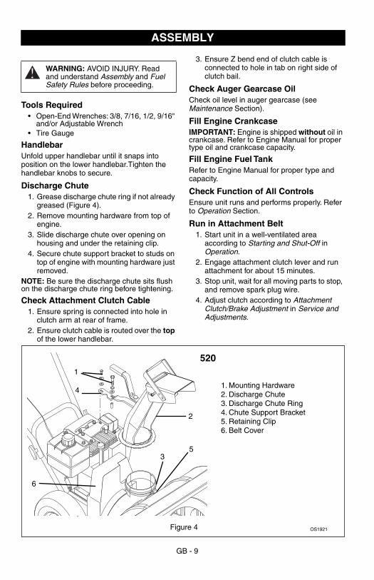
Discharge Chute
1. Grease discharge chute ring if not already greased (Figure 4).
2. Remove mounting hardware from top of engine.
3. Slide discharge chute over opening on housing and under the retaining clip.
4. Secure chute support bracket to studs on top of engine with mounting hardware just removed.
NOTE:
Be sure the discharge chute sits flush on the discharge chute ring before tightening.
Check Attachment Clutch Cable
1. Ensure spring is connected into hole in clutch arm at rear of frame.
2. Ensure clutch cable is routed over the
top
of the lower handlebar.
3. Ensure Z bend end of clutch cable is connected to hole in tab on right side of clutch bail.
Check Auger Gearcase Oil
Check oil level in auger gearcase (see
Maintenance
Section).
Fill Engine Crankcase
IMPORTANT:
Engine is shipped
without
oil in crankcase. Refer to Engine Manual for proper type oil and crankcase capacity.
Fill Engine Fuel Tank
Refer to Engine Manual for proper type and capacity.
Check Function of All Controls
Ensure unit runs and performs properly. Refer to
Operation
Section.
Run in Attachment Belt
1. Start unit in a well-ventilated area according to
Starting and Shut-Off
in
Operation
.2. Engage attachment clutch lever and run
attachment for about 15 minutes.3. Stop unit, wait for all moving parts to stop,
and remove spark plug wire. 4. Adjust clutch according to
Attachment Clutch/Brake Adjustment
in
Service and Adjustments.
ASSEMBLY
WARNING:
AVOID INJURY. Read and understand
Assembly
and
Fuel Safety Rules
before proceeding.
1. Mounting Hardware2. Discharge Chute3. Discharge Chute Ring4. Chute Support Bracket5. Retaining Clip6. Belt Cover
1
2
4
3
OS1921
5
520
6
Figure 4
GB - 10
CONTROLS AND FEATURESSee Figure 1 for all Controls and Features.
Discharge Chute DeflectorALWAYS position discharge chute deflector at a safe angle before starting engine. DO NOT throw snow any higher than necessary.Push deflector handle forward or down to throw snow lower. Pull deflector handle up or to the rear to throw snow higher.IMPORTANT: If Chute Deflector does not stay in set position, adjust as directed in Service and Adjustments, or repair before operation.
Discharge Chute Discharge chute rotates 220°.ALWAYS position discharge chute in safe direction and angle, away from operator and bystanders, before starting engine.
IMPORTANT: If chute does not stay in set position, adjust as directed in Service and Adjustments, or repair before operation.Rotate the Chute with Chute Control Lever.IMPORTANT: DO NOT force frozen chute controls. Start engine and run for 3-5 minutes to thaw. If still frozen, take to warm place until controls are free.
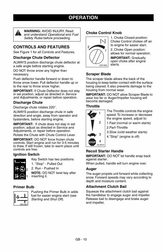
Ignition SwitchKey Switch has two positions:1. "Stop" - Pulled Out2. Run - Pushed InNOTE: DO NOT twist key after inserting it.
Primer BulbPushing the Primer Bulb in adds fuel for easier engine start (see Starting and Shut Off).
Choke Control Knob1. Choke Closed position: Choke Control chokes off air to engine for easier start.2. Choke Open position: allows for normal operation.IMPORTANT: Gradually open choke after engine starts.
Scraper BladeThe scraper blade allows the back of the housing to keep better contact with the surface being cleared. It also prevents damage to the housing from normal wear.IMPORTANT: DO NOT allow Scraper Blade to wear too far or Auger/Impeller housing will become damaged.
ThrottleThe Throttle controls the engine speed. To increase or decrease the engine speed, adjust to:1.Fast (normal or warm starts)2.Part-Throttle3.Slow (cold weather starts)4."Stop" (engine is off)
Recoil Starter HandleIMPORTANT: DO NOT let handle snap back against starter.When pulled, handle will turn engine over.
AugerThe auger propels unit forward while collecting snow. Forward speeds may vary according to depth and moisture content.
Attachment Clutch BailSqueeze the attachment clutch bail against the handlebar to engage auger and impeller. Release bail to disengage and brake auger and impeller.
OPERATION
WARNING: AVOID INJURY. Read and understand Operational and Fuel Safety Rules before proceeding.
2
1
OS1321
21
OS1300
STOPOL2072
1
2
3
4
GB - 11
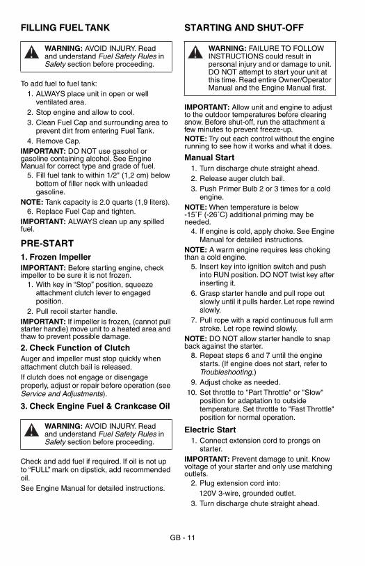
FILLING FUEL TANK
To add fuel to fuel tank:1. ALWAYS place unit in open or well
ventilated area.2. Stop engine and allow to cool.3. Clean Fuel Cap and surrounding area to
prevent dirt from entering Fuel Tank.4. Remove Cap.
IMPORTANT: DO NOT use gasohol or gasoline containing alcohol. See Engine Manual for correct type and grade of fuel.
5. Fill fuel tank to within 1/2" (1,2 cm) below bottom of filler neck with unleaded gasoline.
NOTE: Tank capacity is 2.0 quarts (1,9 liters).6. Replace Fuel Cap and tighten.
IMPORTANT: ALWAYS clean up any spilled fuel.
PRE-START1. Frozen ImpellerIMPORTANT: Before starting engine, check impeller to be sure it is not frozen.
1. With key in “Stop” position, squeeze attachment clutch lever to engaged position.
2. Pull recoil starter handle. IMPORTANT: If impeller is frozen, (cannot pull starter handle) move unit to a heated area and thaw to prevent possible damage.
2. Check Function of ClutchAuger and impeller must stop quickly when attachment clutch bail is released.If clutch does not engage or disengage properly, adjust or repair before operation (see Service and Adjustments).
3. Check Engine Fuel & Crankcase Oil
Check and add fuel if required. If oil is not up to “FULL” mark on dipstick, add recommended oil.See Engine Manual for detailed instructions.
STARTING AND SHUT-OFF
IMPORTANT: Allow unit and engine to adjust to the outdoor temperatures before clearing snow. Before shut-off, run the attachment a few minutes to prevent freeze-up.NOTE: Try out each control without the engine running to see how it works and what it does.
Manual Start1. Turn discharge chute straight ahead.2. Release auger clutch bail.3. Push Primer Bulb 2 or 3 times for a cold
engine.NOTE: When temperature is below -15˚F (-26˚C) additional priming may be needed.
4. If engine is cold, apply choke. See Engine Manual for detailed instructions.
NOTE: A warm engine requires less choking than a cold engine.
5. Insert key into ignition switch and push into RUN position. DO NOT twist key after inserting it.
6. Grasp starter handle and pull rope out slowly until it pulls harder. Let rope rewind slowly.
7. Pull rope with a rapid continuous full arm stroke. Let rope rewind slowly.
NOTE: DO NOT allow starter handle to snap back against the starter.
8. Repeat steps 6 and 7 until the engine starts. (If engine does not start, refer to Troubleshooting.)
9. Adjust choke as needed.10. Set throttle to "Part Throttle" or "Slow"
position for adaptation to outside temperature. Set throttle to "Fast Throttle" position for normal operation.
Electric Start1. Connect extension cord to prongs on
starter.IMPORTANT: Prevent damage to unit. Know voltage of your starter and only use matching outlets.
2. Plug extension cord into:120V 3-wire, grounded outlet.
3. Turn discharge chute straight ahead.
WARNING: AVOID INJURY. Read and understand Fuel Safety Rules in Safety section before proceeding.
WARNING: AVOID INJURY. Read and understand Fuel Safety Rules in Safety section before proceeding.
WARNING: FAILURE TO FOLLOW INSTRUCTIONS could result in personal injury and or damage to unit. DO NOT attempt to start your unit at this time. Read entire Owner/Operator Manual and the Engine Manual first.
GB - 12
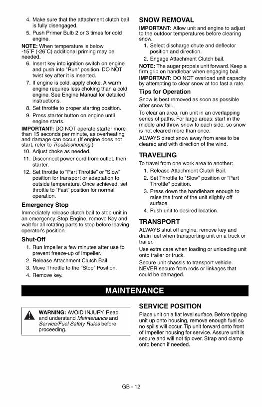
4. Make sure that the attachment clutch bail is fully disengaged.
5. Push Primer Bulb 2 or 3 times for cold engine.
NOTE: When temperature is below -15˚F (-26˚C) additional priming may be needed.
6. Insert key into ignition switch on engine and push into "Run" position. DO NOT twist key after it is inserted.
7. If engine is cold, apply choke. A warm engine requires less choking than a cold engine. See Engine Manual for detailed instructions.
8. Set throttle to proper starting position.9. Press starter button on engine until
engine starts.IMPORTANT: DO NOT operate starter more than 15 seconds per minute, as overheating and damage can occur. (If engine does not start, refer to Troubleshooting.)10. Adjust choke as needed.11. Disconnect power cord from outlet, then
starter.12. Set throttle to “Part Throttle” or “Slow”
position for transport or adaptation to outside temperature. Once achieved, set throttle to “Fast” position for normal operation.
Emergency StopImmediately release clutch bail to stop unit in an emergency. Stop Engine, remove Key and wait for all rotating parts to stop before leaving operator’s position.
Shut-Off1. Run Impeller a few minutes after use to
prevent freeze-up of Impeller.2. Release Attachment Clutch Bail.3. Move Throttle to the "Stop" Position.4. Remove key.
SNOW REMOVALIMPORTANT: Allow unit and engine to adjust to the outdoor temperatures before clearing snow.
1. Select discharge chute and deflector position and direction.
2. Engage Attachment Clutch bail.NOTE: The auger propels unit forward. Keep a firm grip on handlebar when engaging bail. IMPORTANT: DO NOT overload unit capacity by attempting to clear snow at too fast a rate.
Tips for OperationSnow is best removed as soon as possible after snow fall.To clear an area, run unit in an overlapping series of paths. For large areas; start in the middle and throw snow to each side, so snow is not cleared more than once.ALWAYS direct snow away from area to be cleared and with direction of the wind.
TRAVELINGTo travel from one work area to another:
1. Release Attachment Clutch Bail.2. Set Throttle to "Slow" position or "Part
Throttle" position. 3. Press down the handlebars enough to
raise the front of the unit slightly off surface.
4. Push unit to desired location.
TRANSPORTALWAYS shut off engine, remove key and drain fuel when transporting unit on a truck or trailer.Use extra care when loading or unloading unit onto trailer or truck.Secure unit chassis to transport vehicle. NEVER secure from rods or linkages that could be damaged.
SERVICE POSITIONPlace unit on a flat level surface. Before tipping unit up onto housing, remove enough fuel so no spills will occur. Tip unit forward onto front of Impeller housing for service. Assure unit is secure and will not tip over. Strap and clamp onto bench if needed.
MAINTENANCE
WARNING: AVOID INJURY. Read and understand Maintenance and Service/Fuel Safety Rules before proceeding.
GB - 13
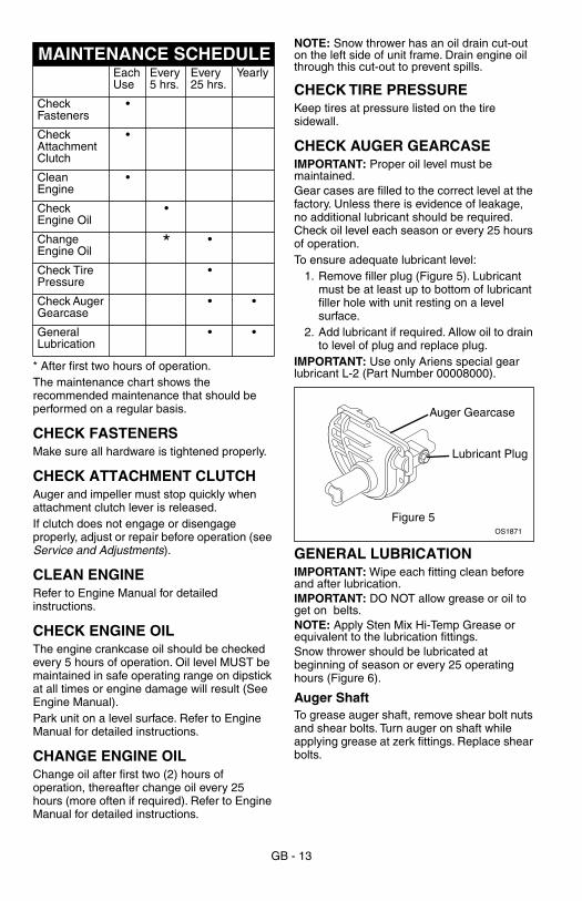
* After first two hours of operation.The maintenance chart shows the recommended maintenance that should be performed on a regular basis.
CHECK FASTENERSMake sure all hardware is tightened properly.
CHECK ATTACHMENT CLUTCHAuger and impeller must stop quickly when attachment clutch lever is released.If clutch does not engage or disengage properly, adjust or repair before operation (see Service and Adjustments).
CLEAN ENGINERefer to Engine Manual for detailed instructions.
CHECK ENGINE OILThe engine crankcase oil should be checked every 5 hours of operation. Oil level MUST be maintained in safe operating range on dipstick at all times or engine damage will result (See Engine Manual).Park unit on a level surface. Refer to Engine Manual for detailed instructions.
CHANGE ENGINE OILChange oil after first two (2) hours of operation, thereafter change oil every 25 hours (more often if required). Refer to Engine Manual for detailed instructions.
NOTE: Snow thrower has an oil drain cut-out on the left side of unit frame. Drain engine oil through this cut-out to prevent spills.
CHECK TIRE PRESSUREKeep tires at pressure listed on the tire sidewall.
CHECK AUGER GEARCASE IMPORTANT: Proper oil level must be maintained.Gear cases are filled to the correct level at the factory. Unless there is evidence of leakage, no additional lubricant should be required. Check oil level each season or every 25 hours of operation.To ensure adequate lubricant level:
1. Remove filler plug (Figure 5). Lubricant must be at least up to bottom of lubricant filler hole with unit resting on a level surface.
2. Add lubricant if required. Allow oil to drain to level of plug and replace plug.
IMPORTANT: Use only Ariens special gear lubricant L-2 (Part Number 00008000).
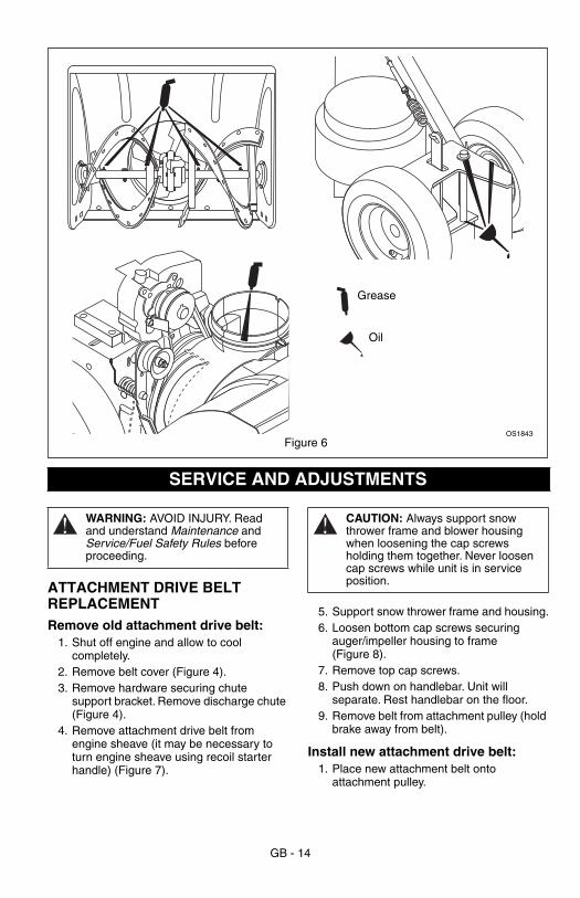
GENERAL LUBRICATIONIMPORTANT: Wipe each fitting clean before and after lubrication.IMPORTANT: DO NOT allow grease or oil to get on belts.NOTE: Apply Sten Mix Hi-Temp Grease or equivalent to the lubrication fittings. Snow thrower should be lubricated at beginning of season or every 25 operating hours (Figure 6).
Auger ShaftTo grease auger shaft, remove shear bolt nuts and shear bolts. Turn auger on shaft while applying grease at zerk fittings. Replace shear bolts.
MAINTENANCE SCHEDULEEach Use
Every 5 hrs.
Every 25 hrs.
Yearly
Check Fasteners
•
Check Attachment Clutch
•
Clean Engine
•
Check Engine Oil
•
Change Engine Oil * •
Check Tire Pressure
•
Check Auger Gearcase
• •
General Lubrication
• •
Auger Gearcase
Lubricant Plug
OS1871
Figure 5
GB - 14
ATTACHMENT DRIVE BELT REPLACEMENTRemove old attachment drive belt:
1. Shut off engine and allow to cool completely.
2. Remove belt cover (Figure 4). 3. Remove hardware securing chute
support bracket. Remove discharge chute (Figure 4).
4. Remove attachment drive belt from engine sheave (it may be necessary to turn engine sheave using recoil starter handle) (Figure 7).
5. Support snow thrower frame and housing.6. Loosen bottom cap screws securing
auger/impeller housing to frame (Figure 8).
7. Remove top cap screws.8. Push down on handlebar. Unit will
separate. Rest handlebar on the floor.9. Remove belt from attachment pulley (hold
brake away from belt).
Install new attachment drive belt:1. Place new attachment belt onto
attachment pulley.
OS1843
Grease
Oil
Figure 6
SERVICE AND ADJUSTMENTS
WARNING: AVOID INJURY. Read and understand Maintenance and Service/Fuel Safety Rules before proceeding.
CAUTION: Always support snow thrower frame and blower housing when loosening the cap screws holding them together. Never loosen cap screws while unit is in service position.

GB - 15
2. Engage clutch bail to hold brake out of the way and tip unit back together. Secure with cap screws.
3. Place belt onto engine sheave.4. Make sure engine sheave and attachment
pulley align. If alignment is necessary, loosen attachment pulley set screws, reposition pulley and tighten set screws.
5. Reposition and secure belt fingers.IMPORTANT: Make sure belt fingers are 1/16" to 1/8" (2-3mm) from belt when attachment clutch is engaged.
6. Check clutch adjustment. See Attachment
Clutch/Brake.
7. Replace discharge chute.8. Replace belt cover.
WARNING: AUGER / IMPELLER MUST STOP within 3 seconds when attachment clutch lever is released or unit damage or serious injury may result.
1. Engine Sheave2. Attachment Pulley3. Attachment Belt4. Attachment Brake5. Brake Shoe6. Idler Pulley7. Belt Finger
OS1820
1
2
3
4
5
7
6
Figure 7
Cap Screws
OS1881Figure 8
GB - 16
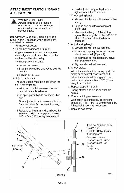
ATTACHMENT CLUTCH / BRAKE ADJUSTMENT
IMPORTANT: AUGER/IMPELLER MUST STOP within 3 seconds when attachment clutch bail is released.
1. Remove belt cover. 2. Check belt alignment (Figure 9).
Engine sheave and attachment pulley must align vertically. Also, belt must be centered in the idler pulley.To move pulley or sheave:
a.Loosen set screw.b.Slide pulley/sheave and key to desired
position.c.Tighten set screw.
3. Adjust cable slack.The clutch cable must be slack when the bail is disengaged.
a.With clutch bail disengaged, loosen jam nut on cable adjuster.
b.Lift spring arm, but do not move idler arm.
c.Turn adjuster body to remove all slack from the cable. Do not stretch spring or move idler arm.
d.Release spring arm and turn back the adjuster body 5 turns (approximately 1/4” or 6mm). Finger tighten jam nut.
e.Hold adjuster body with pliers and tighten jam nut with wrench.
4. Check spring length.a.Measure the length of the clutch cable
spring.
b.Engage and hold the attachment clutch bail.
c.Measure the length of the spring again. The spring should be 1/8”- 3/16” (3-5mm) longer when the bail is engaged.
5. Adjust spring length.a.Loosen the idler adjustment nut.
b.To increase spring extension, move idler towards belt (Figure 7).
c.To decrease spring extension, move idler away from belt.
d.Tighten idler adjustment nut.6. Check brake.
When the clutch bail is disengaged, the brake must contact attachment belt.When the clutch bail is engaged, the brake must be more than 1/16” (2mm) away from the belt.
7. Repeat steps 4 – 6 until:Spring stretch and brake contact are correct.
8. Check belt finger clearance.With clutch bail engaged, belt fingers should be 1/16” – 1/8” (2–3mm) from belt. Adjust belt fingers as necessary.
9. Replace belt cover.
WARNING: IMPROPER ADJUSTMENT could result in unexpected movement of auger and impeller causing death or serious injury.
1. Cable Adjuster Body2. Jam Nut3. Clutch Cable Spring4. Spring Arm5. Engine Sheave6. Attachment Pulley7. Attachment Belt8. Idler9. Idler Arm
1
2
3
4
OS2201Figure 9
7
5
8
6
9
1/8"–3/16"(3–5 mm)
GB - 17
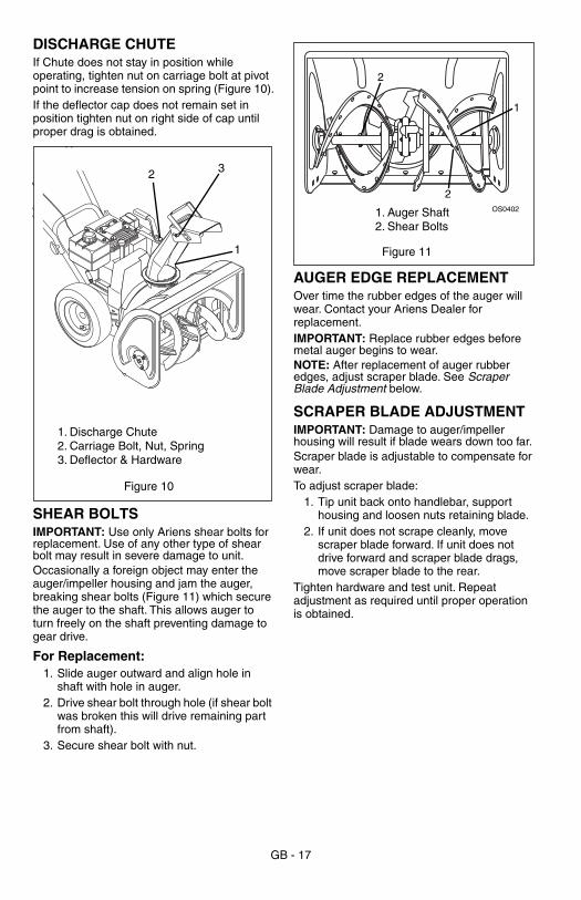
DISCHARGE CHUTEIf Chute does not stay in position while operating, tighten nut on carriage bolt at pivot point to increase tension on spring (Figure 10).If the deflector cap does not remain set in position tighten nut on right side of cap until proper drag is obtained.
SHEAR BOLTSIMPORTANT: Use only Ariens shear bolts for replacement. Use of any other type of shear bolt may result in severe damage to unit.Occasionally a foreign object may enter the auger/impeller housing and jam the auger, breaking shear bolts (Figure 11) which secure the auger to the shaft. This allows auger to turn freely on the shaft preventing damage to gear drive.
For Replacement:1. Slide auger outward and align hole in
shaft with hole in auger.2. Drive shear bolt through hole (if shear bolt
was broken this will drive remaining part from shaft).
3. Secure shear bolt with nut.
AUGER EDGE REPLACEMENTOver time the rubber edges of the auger will wear. Contact your Ariens Dealer for replacement.IMPORTANT: Replace rubber edges before metal auger begins to wear.NOTE: After replacement of auger rubber edges, adjust scraper blade. See Scraper Blade Adjustment below.
SCRAPER BLADE ADJUSTMENTIMPORTANT: Damage to auger/impeller housing will result if blade wears down too far.Scraper blade is adjustable to compensate for wear.To adjust scraper blade:
1. Tip unit back onto handlebar, support housing and loosen nuts retaining blade.
2. If unit does not scrape cleanly, move scraper blade forward. If unit does not drive forward and scraper blade drags, move scraper blade to the rear.
Tighten hardware and test unit. Repeat adjustment as required until proper operation is obtained.
1
2 3
1. Discharge Chute2. Carriage Bolt, Nut, Spring3. Deflector & Hardware
Figure 10
1
2
1. Auger Shaft2. Shear Bolts
OS0402
2
Figure 11
GB - 18
SHORT TERMIMPORTANT: NEVER spray unit with water or store unit outdoors.Run with attachment clutch engaged a few minutes after each use to free unit of any loose or melting snow.Inspect unit for visible signs of wear, breakage or damage.
Keep all nuts, bolts and screws properly tightened and know unit is in safe working condition.Store unit in a cool, dry protected area.
LONG TERMClean unit thoroughly and lubricate (see Maintenance). Touch up all scratched painted surfaces.Remove weight from wheels by putting blocks under frame or axle.When storing unit for extended periods of time, remove all fuel from tank and carburetor (run dry). Refer to Engine Manual.
STORAGE
WARNING: AVOID INJURY. Read and understand Storage Safety Rules in Safety section before proceeding.
TROUBLESHOOTINGPROBLEM PROBABLE CAUSE CORRECTION
Engine will not crank/start.
1. Fuel tank is empty.2. Build up of dirt and residue
around governor/carburetor.3. Key Switch not in run
position.4. Ignition switch starter circuit
not functioning.5. Engine ignition problems.
1. Fill fuel tank.2. Clean area around governor/
carburetor.3. Put Key Switch into run
position.4. Check for a bad starter or
connections.5. See Engine Manual.
Engine stops. 1. Out of fuel.2. Mechanical jam in blower
rake or impeller.3. Polluted fuel supply.4. Faulty spark plug.
1. Fill fuel tank.2. Turn off engine, remove key,
and wait for all moving parts to stop. Check for and remove obstruction and repair before restart.
3. Replace with clean fuel.4. Replace or clean spark plug.
Engine problems. See Engine Manual.
ACCESSORIESSee your authorized Ariens dealer to add the additional accessories available for your snow thrower.
Part No. Description
73203100 Slicer Bar
GB - 19
To obtain a complete parts manual, find your model and serial number. Then call 1-866-622-5633.
SERVICE PARTSBe sure to always use genuine Ariens parts to keep your snow thrower running like new.
Part No. Description
53200500 Shear Bolt Replacement Kit
03243657 Scraper Blade
07211400 Impeller Belt
21533400 Spark Plug
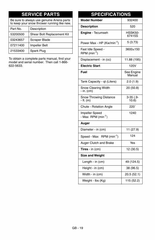
SPECIFICATIONSModel Number 932400
Description 520
Engine - Tecumseh HSSK50-67415S
Power Max - HP (Kw/min-1) 5 (3.73)
Fast Idle Speed - RPM (min-1)
3600±150
Displacement - in (cc) 11.88 (195)
Electric Start 120V
Fuel See Engine Manual
Tank Capacity - qt (Liters) 2.0 (1.9)
Snow Clearing Width - in. (cm)
20 (50.8)
Snow Throwing Distance- ft. (m)
3-35 (.9-10.6)
Chute - Rotation Angle 220˚
Impeller Speed - Max RPM (min-1)
1240
Auger
Diameter - in (cm) 11 (27.9)
Speed - Max RPM (min-1) 124
Auger Clutch and Brake Yes
Tires - in (cm) 12 (30.5)
Size and Weight
Length - in (cm) 49 (124.5)
Height - in (cm) 38 (96.5)
Width - in (cm) 20.5 (52.1)
Weight - lbs (Kg) 115 (52.2)
GB - 20
2 Year Limited WarrantyAriens Company warrants to the original purchaser that consumer products manufacturedby Ariens Company will be free from defects in material and workmanship for a periodof two (2) years after the date of purchase, and will repair any defect in material orworkmanship, and repair or replace any defective part, subject to the conditions, limitationsand exclusions set forth herein.
The two year duration of this warranty applies only if the product is put to ordinary,reasonable, and usual personal, family, or household uses. If the product is put to anybusiness, commercial, or industrial use such as, but not limited to, commercial landscaping,mowing or snow removal services, or golf course or park maintenance, or agriculturalor farmstead use, then the duration of this warranty is ninety (90) days after the dateof purchase, or one (1) year after the date of purchase if the product is labeled as aProfessional/Commercial Product. If any product is rented or leased, then the durationof this warranty is ninety (90) days after the date of purchase.
Ariens Company655 West Ryan StreetP.O. Box 157Brillion, WI 54110-01571-866-622-5633Fax 920-756-2407www.ariens.com
This warranty is subject to the following conditions, limitations, and exclusions:
This warranty is valid only if the following conditions aremet:
• The warranty registration card must be completed andreturned to Ariens Company.
• The purchaser must perform maintenance and minoradjustments explained in the owner’s manual.
• The purchaser must promptly notify Ariens Company or anauthorized Ariens service representative of the need forwarranty service.
This warranty is subject to the following limitations:• The purchaser must transport the product to and from the
place of warranty service.• Warranty service must be performed by an authorized Ariens
service representative. (To find an authorized Ariens servicerepresentative, contact Ariens Company at the number oraddress above.)
• Batteries are warranted only for a period of twelve (12)months after date of purchase, on a prorated basis. For thefirst ninety (90) days of the warranty period, a defectivebattery will be replaced free of charge. If the applicablewarranty period is more than 90 days, Ariens Company willcover the prorated cost of any defective battery, for up totwelve(12) months after the date of purchase.
The following items are not covered by this warranty:• Engines and engine accessories are covered only by the
warranty made by the engine manufacturer, and are notcovered by this warranty.
• If the product is equipped with a Peerless gearbox and/ortransmission, the gearbox and/or transmission are coveredonly by the warranty made by Peerless, and are not coveredby this warranty.
• Parts that are not genuine Ariens service parts are notcovered by this warranty.
• Shoes, runners, scraper blades, shear bolts, string trimmerheight guide, mower blades, mower vanes, trimmer line,headlights, light bulbs, are not covered by this warranty.
• Any defect which is the result of misuse, alteration, improperassembly, improper adjustment, neglect, or accident, is notcovered by this warranty.
• Products which were not purchased in the United States,Puerto Rico, or Canada are not covered by this warranty.In all other countries, contact place of purchase.
Form: MLW2-121300
DISCLAIMER OF FURTHER WARRANTYAriens Company makes no warranty, expressor implied, other than what is expressly madein this warranty. If the law of your state providesthat an implied warranty of merchantability, oran implied warranty of fitness for particularpurpose, or any other implied warranty, appliesto Ariens Company, then any such impliedwarranty is limited to the duration of thiswarranty. Some states do not allow limitationson how long an implied warranty lasts, so theabove limitation may not apply to you.
LIMITATION OF REMEDY AND DAMAGESAriens Company’s liability under this warranty, and under anyimplied warranty that may exist, is limited to repair of anydefect in workmanship, and repair or replacement of anydefective part. Ariens Company shall not be liable for incidental,special, or consequential damages (including lost profits).Some states do not allow the exclusion of incidental orconsequential damages, so the above limitation or exclusionmay not apply to you.
This warranty gives you specific legal rights, and you may also have other rightswhich vary from state to state.