Embed Size (px)
Citation preview
1
MachiningIntroduction
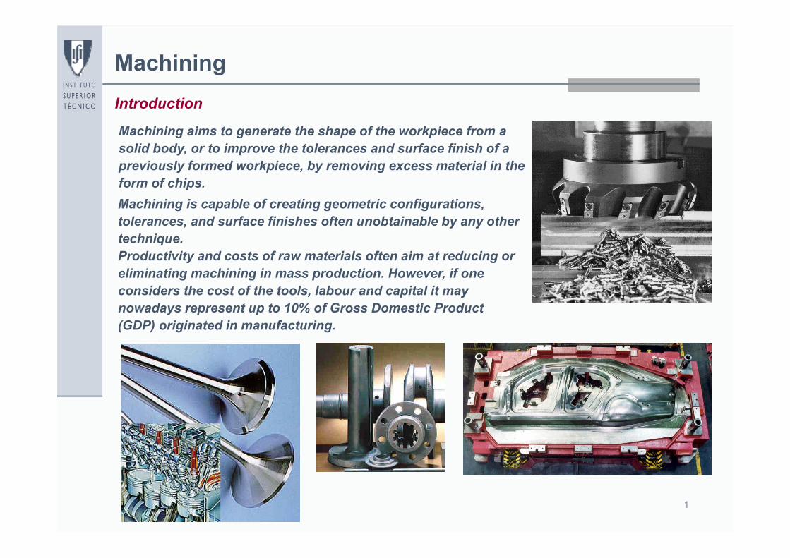
Machining aims to generate the shape of the workpiece from a solid body, or to improve the tolerances and surface finish of a previously formed workpiece, by removing excess material in the form of chips.Machining is capable of creating geometric configurations, tolerances, and surface finishes often unobtainable by any other technique. Productivity and costs of raw materials often aim at reducing or eliminating machining in mass production. However, if one considers the cost of the tools, labour and capital it may nowadays represent up to 10% of Gross Domestic Product (GDP) originated in manufacturing.
2
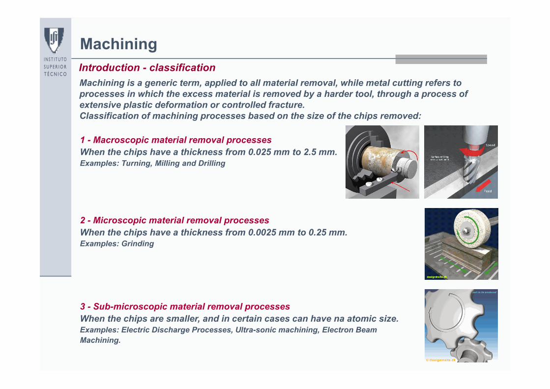
MachiningIntroduction - classificationMachining is a generic term, applied to all material removal, while metal cutting refers to processes in which the excess material is removed by a harder tool, through a process of extensive plastic deformation or controlled fracture.Classification of machining processes based on the size of the chips removed:
1 - Macroscopic material removal processesWhen the chips have a thickness from 0.025 mm to 2.5 mm.Examples: Turning, Milling and Drilling
2 - Microscopic material removal processesWhen the chips have a thickness from 0.0025 mm to 0.25 mm.Examples: Grinding
3 - Sub-microscopic material removal processesWhen the chips are smaller, and in certain cases can have na atomic size.Examples: Electric Discharge Processes, Ultra-sonic machining, Electron Beam Machining.
3
Metal CuttingIntroduction - classification
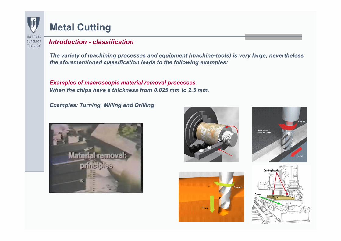
The variety of machining processes and equipment (machine-tools) is very large; nevertheless the aforementioned classification leads to the following examples:
Examples of macroscopic material removal processes When the chips have a thickness from 0.025 mm to 2.5 mm.
Examples: Turning, Milling and Drilling
4
Metal CuttingIntroduction – turning
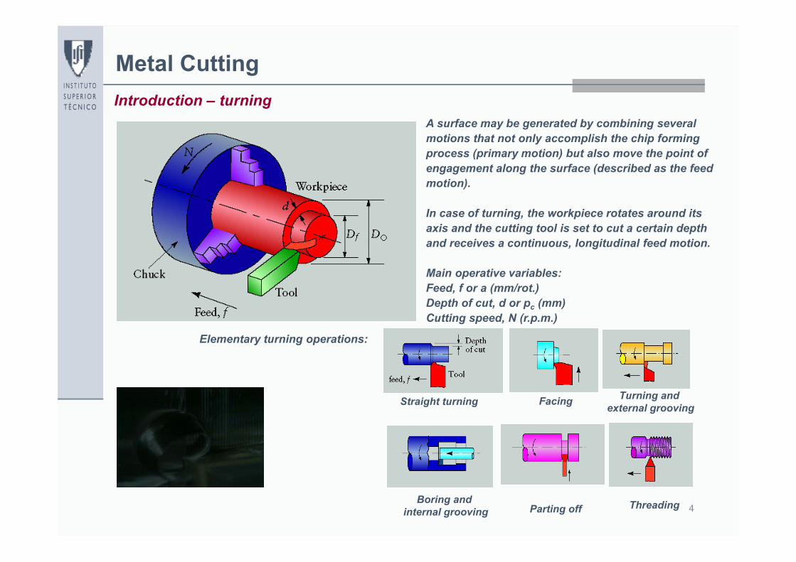
Elementary turning operations:
A surface may be generated by combining several motions that not only accomplish the chip forming process (primary motion) but also move the point of engagement along the surface (described as the feed motion).
In case of turning, the workpiece rotates around its axis and the cutting tool is set to cut a certain depth and receives a continuous, longitudinal feed motion.
Main operative variables:Feed, f or a (mm/rot.)Depth of cut, d or pc (mm)Cutting speed, N (r.p.m.)
Straight turning Facing Turning and external grooving
Parting off ThreadingBoring and internal grooving
5
Metal CuttingIntroduction – milling
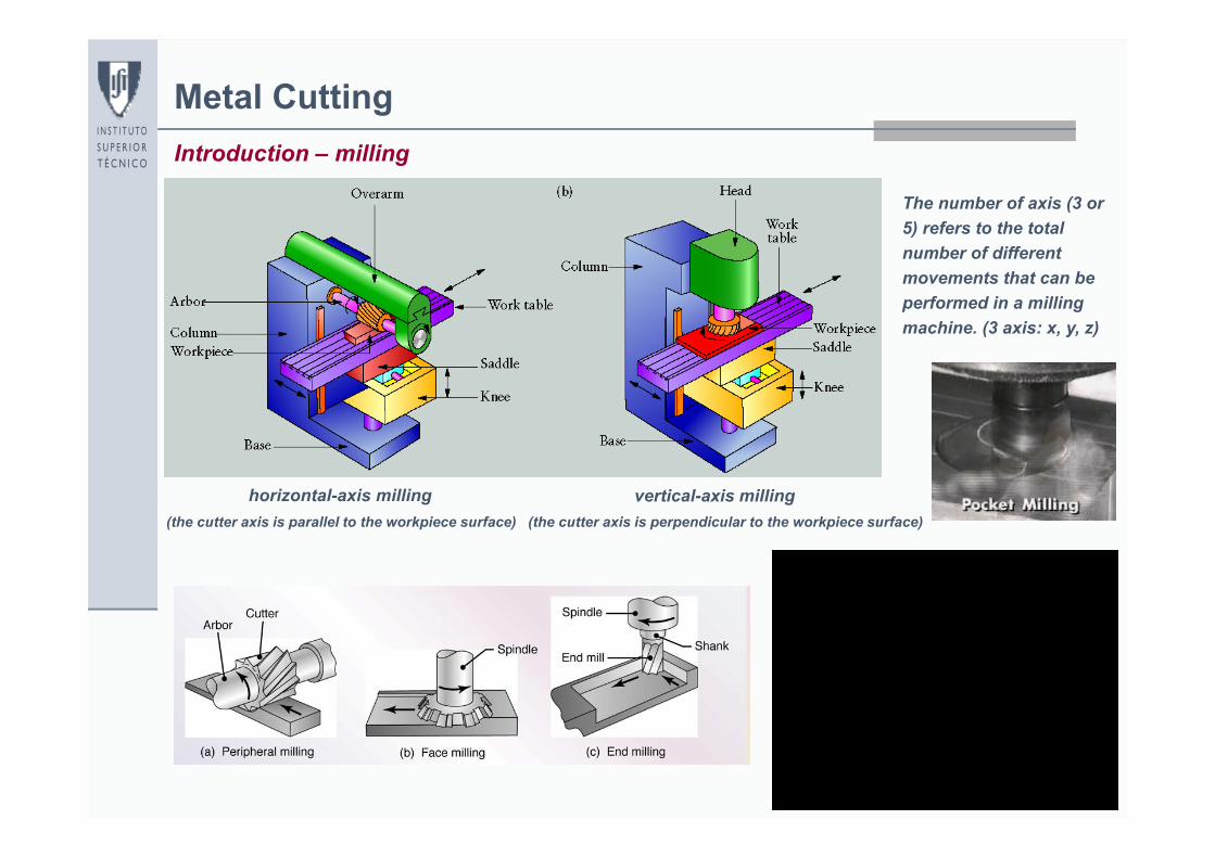
The number of axis (3 or 5) refers to the total number of different movements that can be performed in a milling machine. (3 axis: x, y, z)
horizontal-axis milling vertical-axis milling(the cutter axis is parallel to the workpiece surface) (the cutter axis is perpendicular to the workpiece surface)
6
Metal CuttingIntroduction – grinding
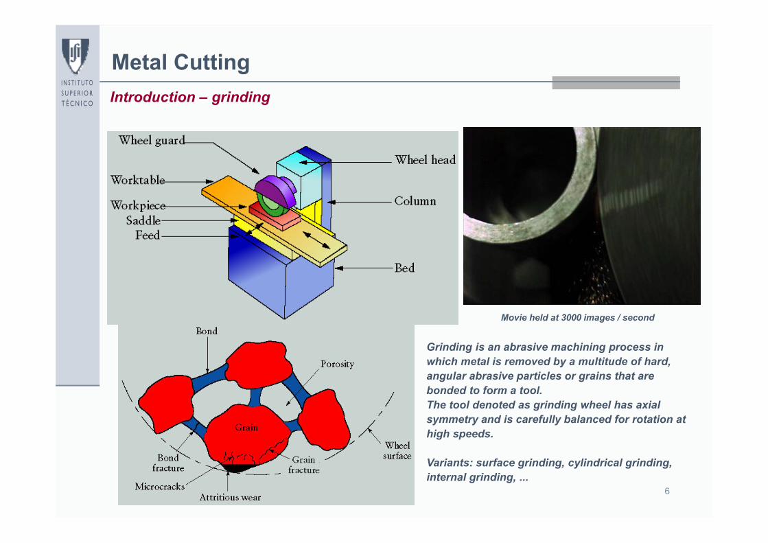
Grinding is an abrasive machining process in which metal is removed by a multitude of hard, angular abrasive particles or grains that are bonded to form a tool.The tool denoted as grinding wheel has axial symmetry and is carefully balanced for rotation at high speeds.
Variants: surface grinding, cylindrical grinding, internal grinding, ...
Movie held at 3000 images / second
7
Metal CuttingIntroduction – advantages and disadvantages
Advantages:
- Manufacturing of parts with high accuracy (eg. punches, dies, ...)- Manufacturing of parts that involve inside or outside complex that are very difficult, or even impossible to fabricate, by means of other manufacturing processes
- Manufacturing of parts with very different surface finish- High flexibility. The machine tools (CNC or conventional) enable to manufacture parts with very different geometries and sizes
- The cutting tools are relatively inexpensive. They are manufactured in large batches with standard geometric shapes and sizes.
- Adequate for small batch production
Disadvantages:
- Material removal involves high energy and material consumption- Production rate is relatively low- Manufacturing of parts usually involves high costs and skilled labour- When procedures are not properly followed one may jeopardize both the quality and the surface properties of the parts to be fabricated
Machining processes play a major key role in the metalworking industry
8
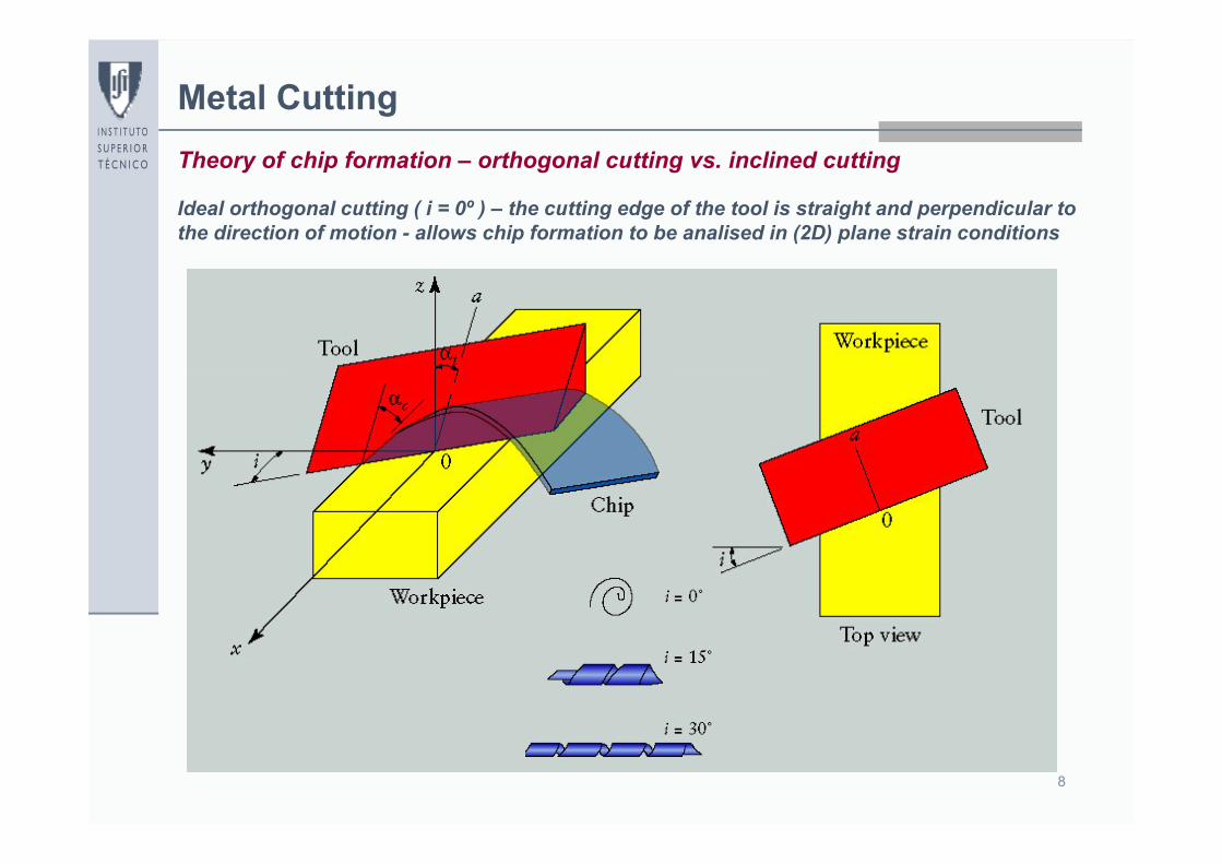
Metal CuttingTheory of chip formation – orthogonal cutting vs. inclined cutting
Ideal orthogonal cutting ( i = 0º ) – the cutting edge of the tool is straight and perpendicular to the direction of motion - allows chip formation to be analised in (2D) plane strain conditions
9
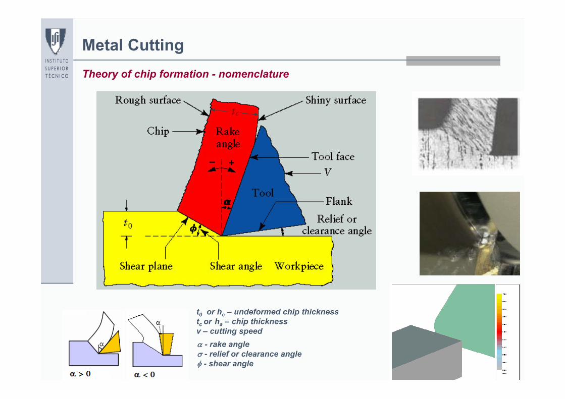
Metal CuttingTheory of chip formation - nomenclature
t0 or hc – undeformed chip thicknesstc or ha – chip thicknessv – cutting speed - rake angle - relief or clearance angle - shear angle
10
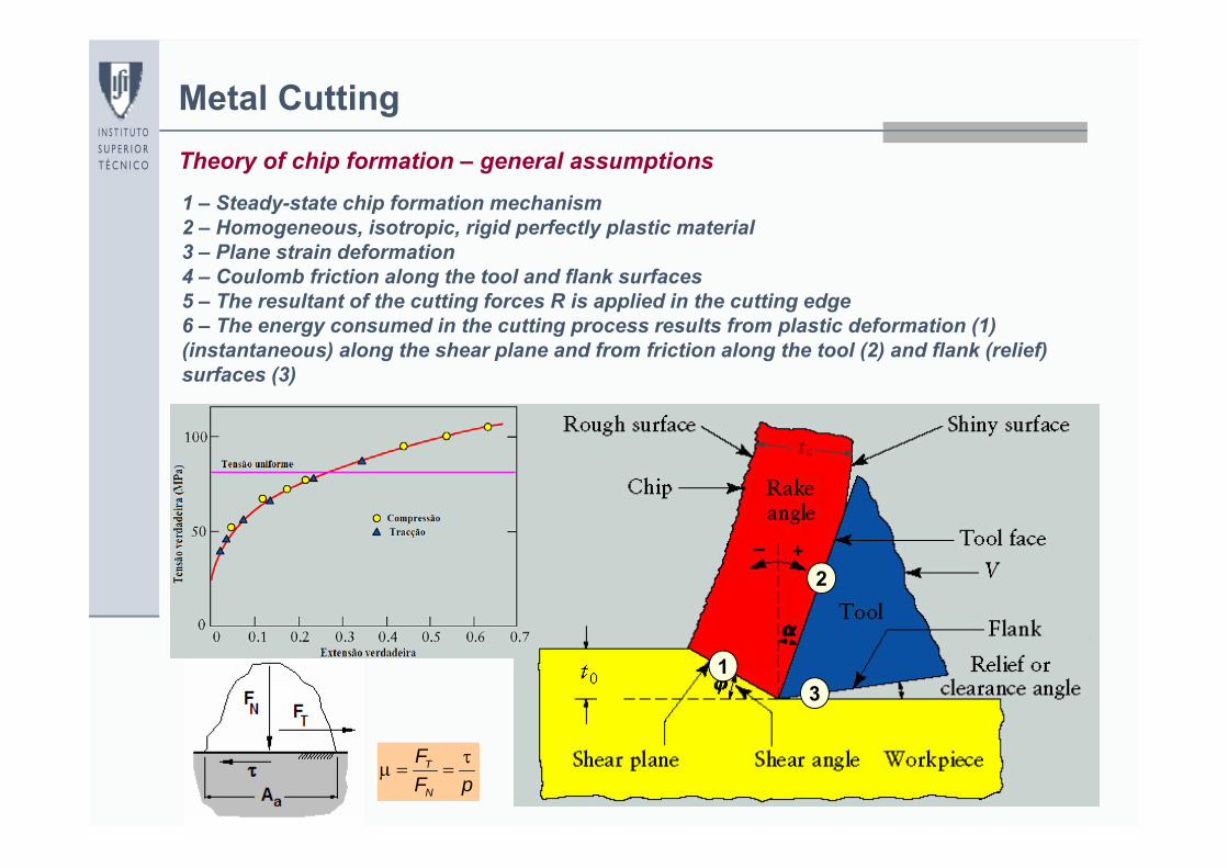
Metal CuttingTheory of chip formation – general assumptions
1 – Steady-state chip formation mechanism2 – Homogeneous, isotropic, rigid perfectly plastic material3 – Plane strain deformation4 – Coulomb friction along the tool and flank surfaces5 – The resultant of the cutting forces R is applied in the cutting edge6 – The energy consumed in the cutting process results from plastic deformation (1) (instantaneous) along the shear plane and from friction along the tool (2) and flank (relief) surfaces (3)
pFF
N
T
R
13
2
11
Metal Cutting
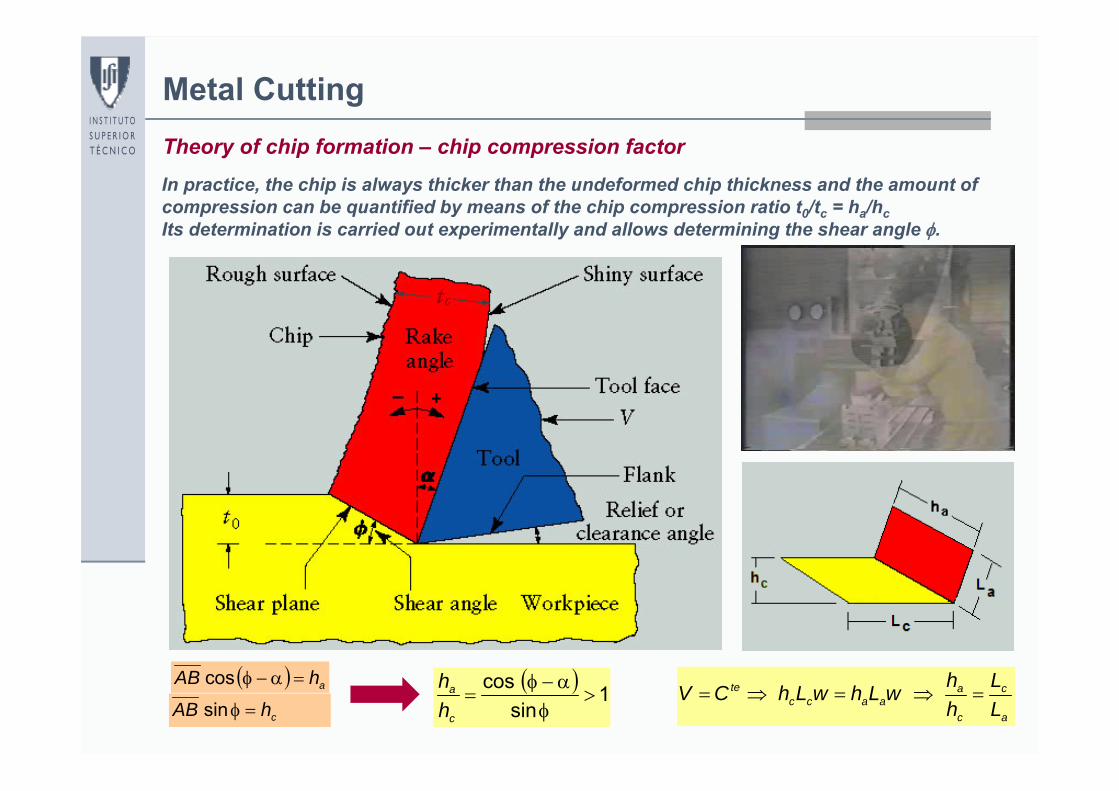
ahAB cos
chAB sin a
c
c
aaacc
te
LL
hhwLhwLhCV
Theory of chip formation – chip compression factorIn practice, the chip is always thicker than the undeformed chip thickness and the amount of compression can be quantified by means of the chip compression ratio t0/tc = ha/hcIts determination is carried out experimentally and allows determining the shear angle .
1sin
cos
c
a
hh
12
Metal Cutting
ac
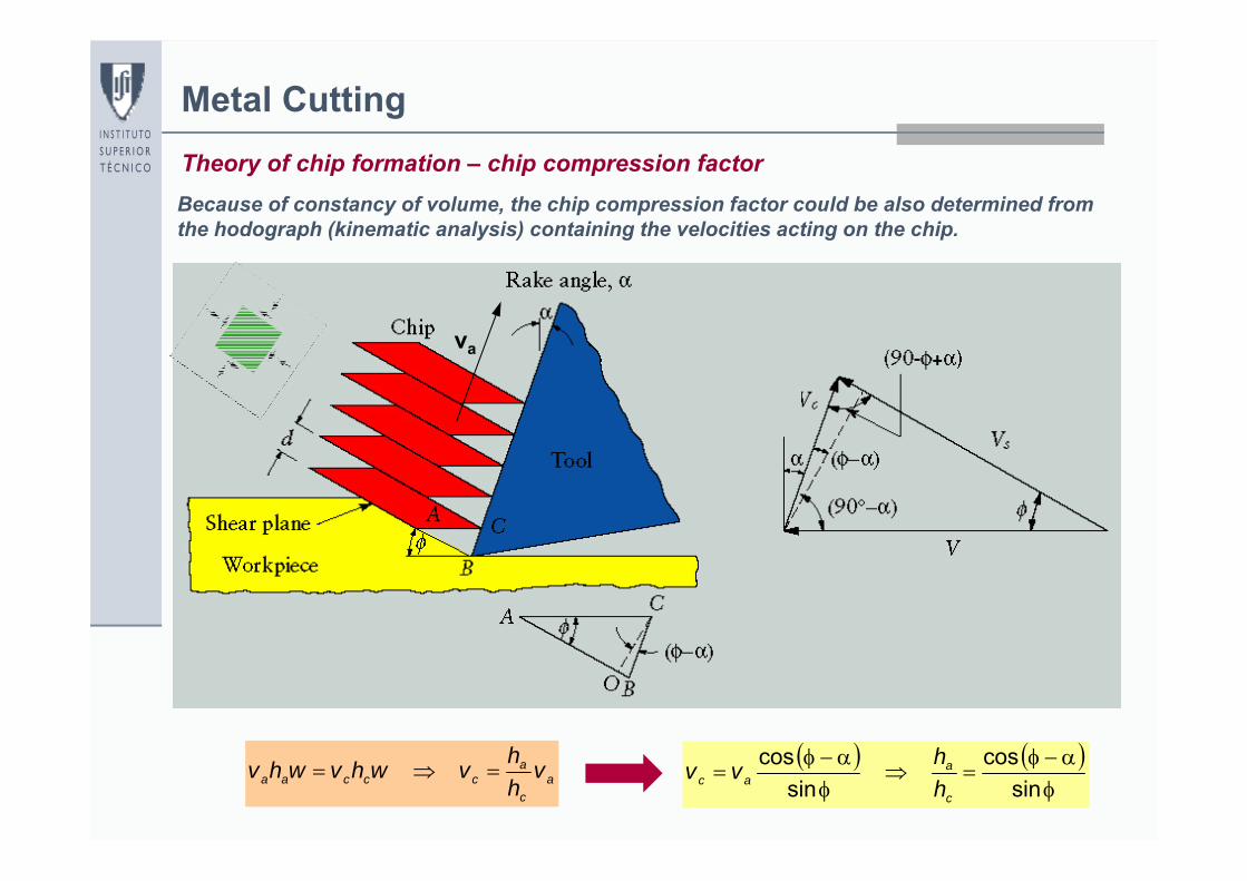
acccaa v
hhvwhvwhv
Theory of chip formation – chip compression factor
sin
cossin
cosc
aac h
hvv
Because of constancy of volume, the chip compression factor could be also determined from the hodograph (kinematic analysis) containing the velocities acting on the chip.
vc
va
13
Metal Cutting
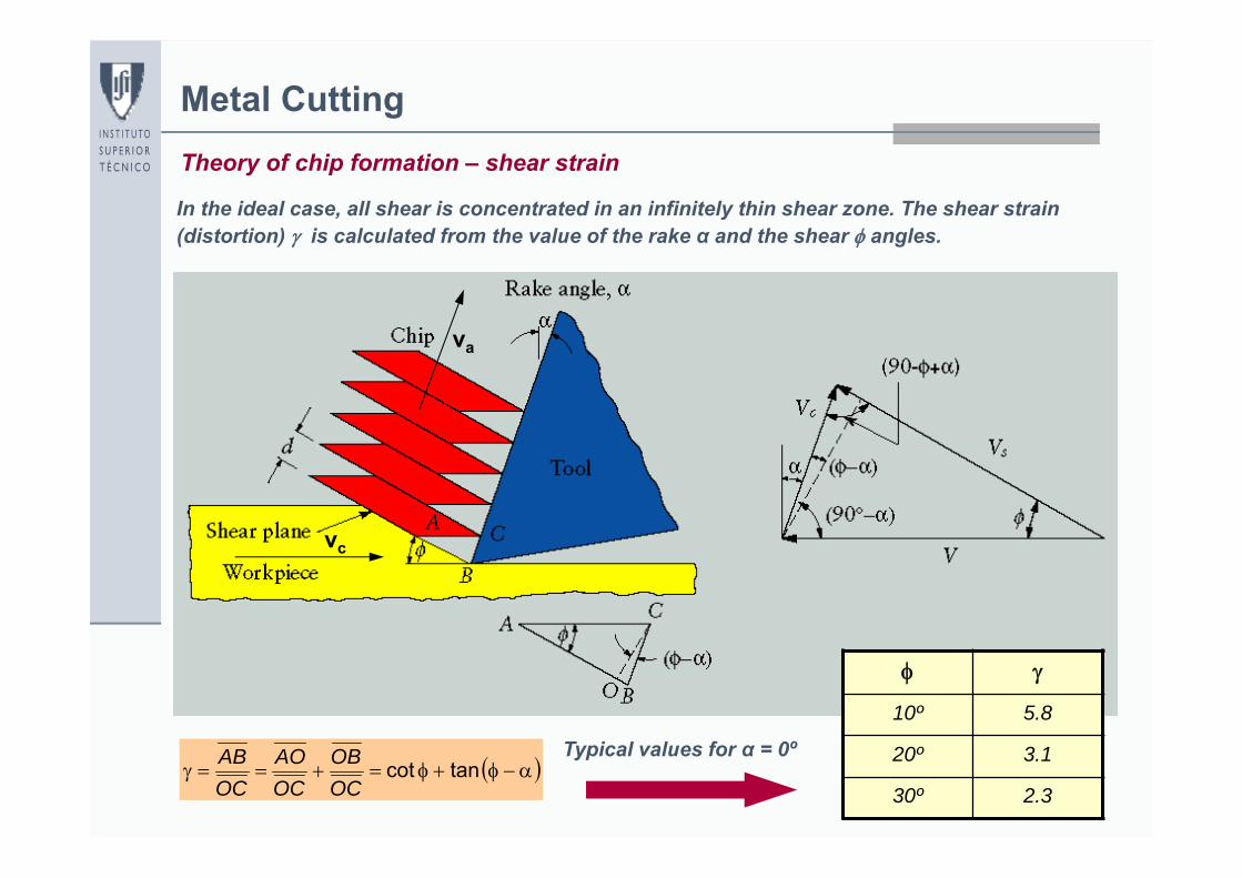
tancotOCOB
OCAO
OCAB
Theory of chip formation – shear strain
In the ideal case, all shear is concentrated in an infinitely thin shear zone. The shear strain (distortion) is calculated from the value of the rake α and the shear angles.
vc
va
10º 5.8
20º 3.1
30º 2.3
Typical values for α = 0º
14
Metal Cutting
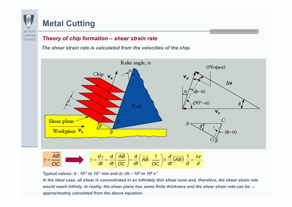
OCAB
Theory of chip formation – shear strain rate
dv
dAB
dtd
OCAB
dtd
OCAB
dtd
dtd
11
The shear strain rate is calculated from the velocities of the chip.
vc
va
Typical values: d - 10-2 to 10-3 mm and d /dt – 103 to 106 s-1
In the ideal case, all shear is concentrated in an infinitely thin shear zone and, therefore, the shear strain rate would reach infinity. In reality, the shear plane has some finite thickness and the shear strain rate can be approximately calculated from the above equation.
va
vc
v
15
Metal Cutting
dv
dtd
tancot
Theory of chip formation – shear strain and shear strain rate
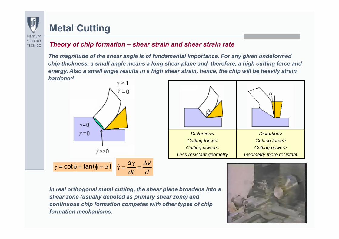
The magnitude of the shear angle is of fundamental importance. For any given undeformed chip thickness, a small angle means a long shear plane and, therefore, a high cutting force and energy. Also a small angle results in a high shear strain, hence, the chip will be heavily strain hardened.
In real orthogonal metal cutting, the shear plane broadens into a shear zone (usually denoted as primary shear zone) and continuous chip formation competes with other types of chip formation mechanisms.
Distortion<Cutting force<Cutting power<
Less resistant geometry
Distortion>Cutting force>Cutting power>
Geometry more resistant
16
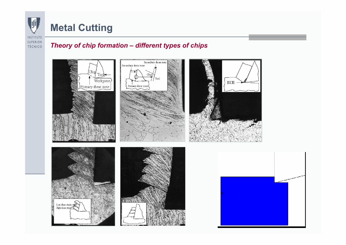
Metal CuttingTheory of chip formation – different types of chips
17
Metal CuttingTheory of chip formation – different types of chips
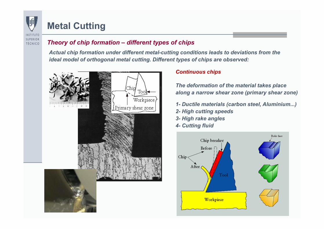
Continuous chips
The deformation of the material takes place along a narrow shear zone (primary shear zone)
1- Ductile materials (carbon steel, Aluminium...)2- High cutting speeds 3- High rake angles4- Cutting fluid
Actual chip formation under different metal-cutting conditions leads to deviations from the ideal model of orthogonal metal cutting. Different types of chips are observed:
18
Metal CuttingTheory of chip formation – different types of chips
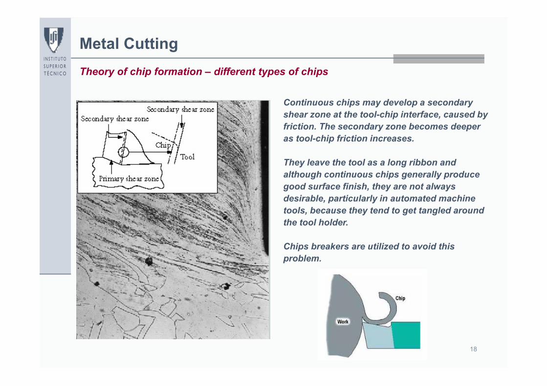
Continuous chips may develop a secondary shear zone at the tool-chip interface, caused by friction. The secondary zone becomes deeper as tool-chip friction increases.
They leave the tool as a long ribbon and although continuous chips generally produce good surface finish, they are not always desirable, particularly in automated machine tools, because they tend to get tangled around the tool holder.
Chips breakers are utilized to avoid this problem.
19
Metal CuttingTheory of chip formation – different types of chips
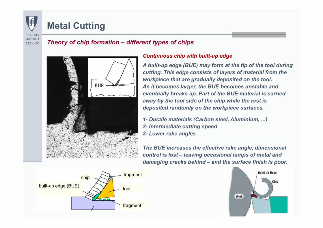
Continuous chip with built-up edge
A built-up edge (BUE) may form at the tip of the tool during cutting. This edge consists of layers of material from the workpiece that are gradually deposited on the tool.As it becomes larger, the BUE becomes unstable and eventually breaks up. Part of the BUE material is carried away by the tool side of the chip while the rest is deposited randomly on the workpiece surfaces.
1- Ductile materials (Carbon steel, Aluminium, ...)2- Intermediate cutting speed3- Lower rake angles
The BUE increases the effective rake angle, dimensional control is lost – leaving occasional lumps of metal and damaging cracks behind – and the surface finish is poor.
chip
built-up edge (BUE) tool
fragment
fragment
20
Metal CuttingTheory of chip formation – different types of chips
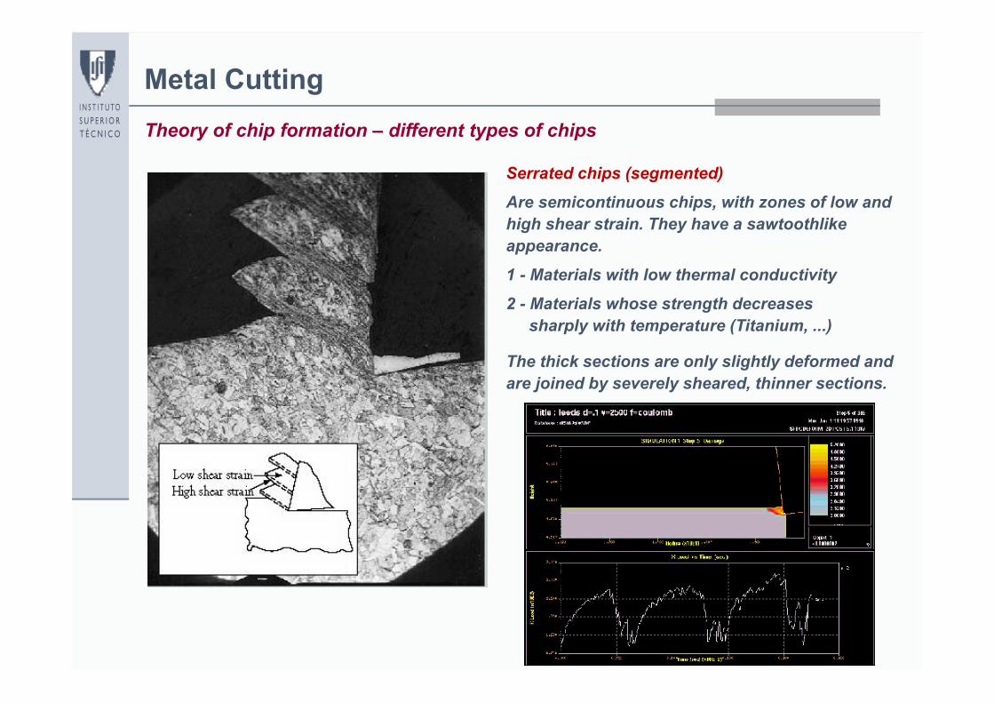
Serrated chips (segmented)
Are semicontinuous chips, with zones of low and high shear strain. They have a sawtoothlike appearance.
1 - Materials with low thermal conductivity
2 - Materials whose strength decreasessharply with temperature (Titanium, ...)
The thick sections are only slightly deformed and are joined by severely sheared, thinner sections.
21
Metal CuttingTheory of chip formation – different types of chips
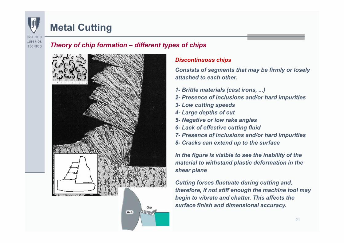
Discontinuous chips
Consists of segments that may be firmly or losely attached to each other.
1- Brittle materials (cast irons, ...)2- Presence of inclusions and/or hard impurities3- Low cutting speeds4- Large depths of cut5- Negative or low rake angles6- Lack of effective cutting fluid7- Presence of inclusions and/or hard impurities8- Cracks can extend up to the surface
In the figure is visible to see the inability of the material to withstand plastic deformation in the shear plane
Cutting forces fluctuate during cutting and, therefore, if not stiff enough the machine tool may begin to vibrate and chatter. This affects the surface finish and dimensional accuracy.
22
Metal CuttingTheory of chip formation – different types of chips
Supe
rfic
ial f
inis
hing
(m
)
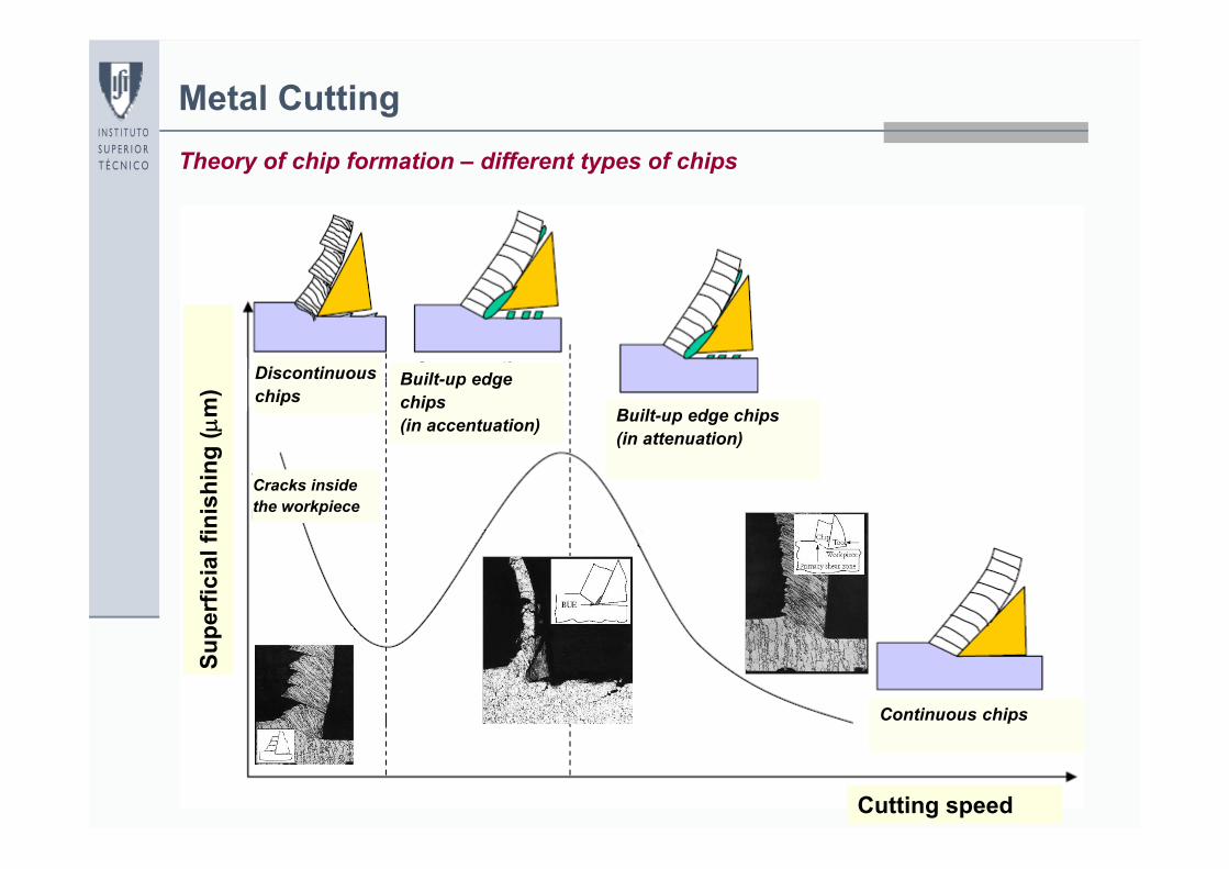
Cutting speed
Continuous chips
Built-up edge chips(in attenuation)
Built-up edge chips (in accentuation)
Discontinuous chips
Cracks inside the workpiece
23
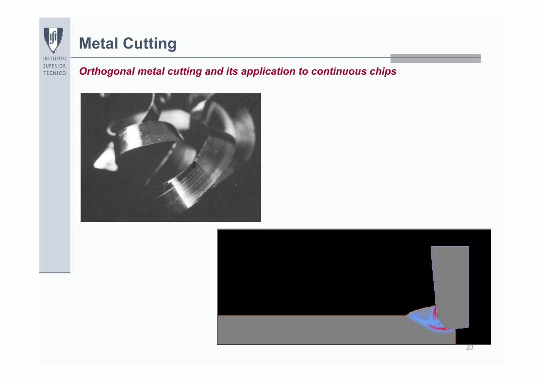
Metal CuttingOrthogonal metal cutting and its application to continuous chips
24
Metal Cutting
Ft
Fn
pF
cF F
F
ha
ferramenta
peça
apara
hc
R
tn
pc
FFR
FFR
FFR
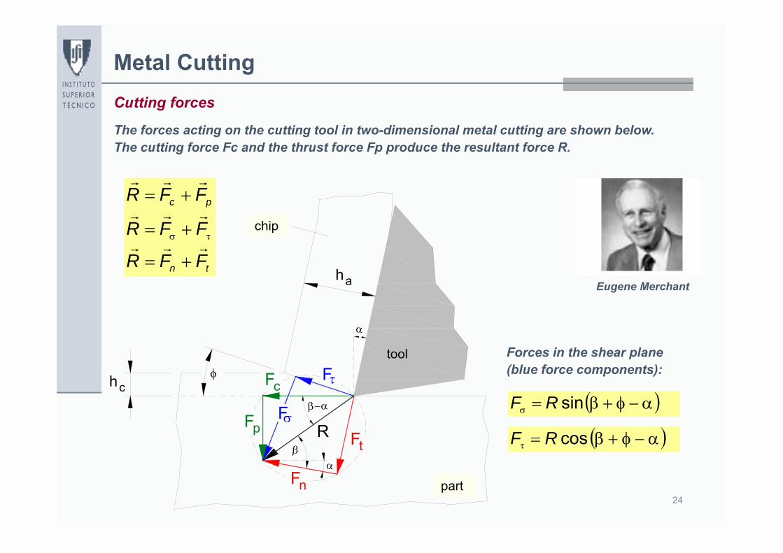
Cutting forces
The forces acting on the cutting tool in two-dimensional metal cutting are shown below.The cutting force Fc and the thrust force Fp produce the resultant force R.
sinRF
cosRF
Forces in the shear plane(blue force components):
Eugene Merchant
chip
part
tool
25
Metal Cutting
Ft
Fn
pF
cF F
F
ha
ferramenta
peça
apara
hc
R
sin
whAA cABCD
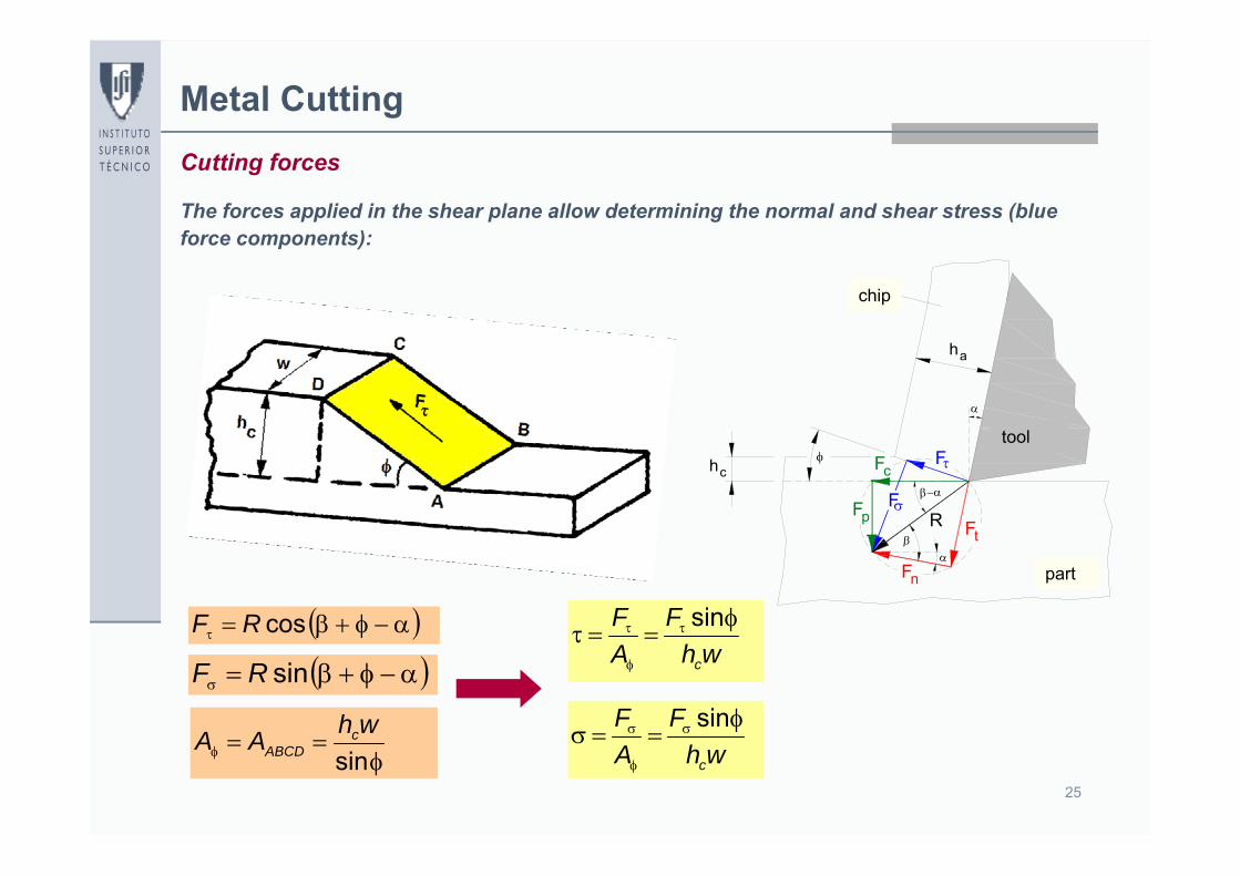
Cutting forces
The forces applied in the shear plane allow determining the normal and shear stress (blue force components):
sinRF
cosRFwh
FAF
c
sin
whF
AF
c
sin
chip
part
tool
26
Metal CuttingCutting forces
cossin pc
t
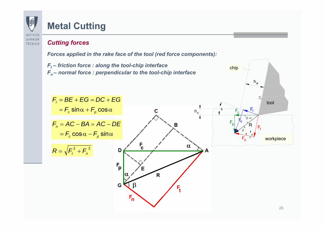
FFEGDCEGBEF
sincos pc
n
FFDEACBAACF
22nt FFR
Forces applied in the rake face of the tool (red force components):
Ft – friction force : along the tool-chip interfaceFn – normal force : perpendicular to the tool-chip interface
Ft
Fn
pF
cF F
F
ha
ferramenta
peça
apara
hc
R
chip
workpiece
tool
27
Metal Cutting
tan
tan1
tantan
sincoscossin
tan
p
c
p
c
pc
cp
pc
pc
n
t
FF
FF
FFFF
FFFF
FF
Cutting forces
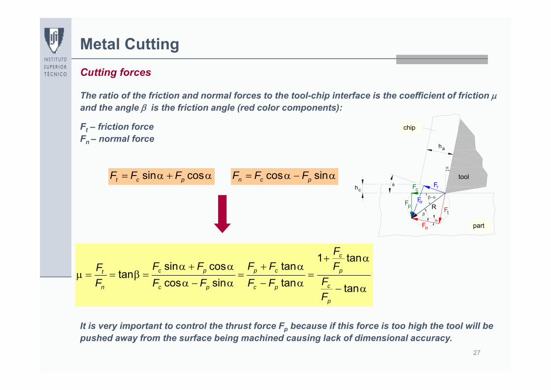
cossin pct FFF sincos pcn FFF
The ratio of the friction and normal forces to the tool-chip interface is the coefficient of friction and the angle is the friction angle (red color components):
Ft – friction forceFn – normal force
It is very important to control the thrust force Fp because if this force is too high the tool will be pushed away from the surface being machined causing lack of dimensional accuracy.
Ft
Fn
pF
cF F
F
ha
ferramenta
peça
apara
hc
R
chip
part
tool
28
Metal Cutting
cosRFc
sinRFp
Ft
Fn
pF
cF F
F
ha
ferramenta
peça
apara
hc
R
Cutting power
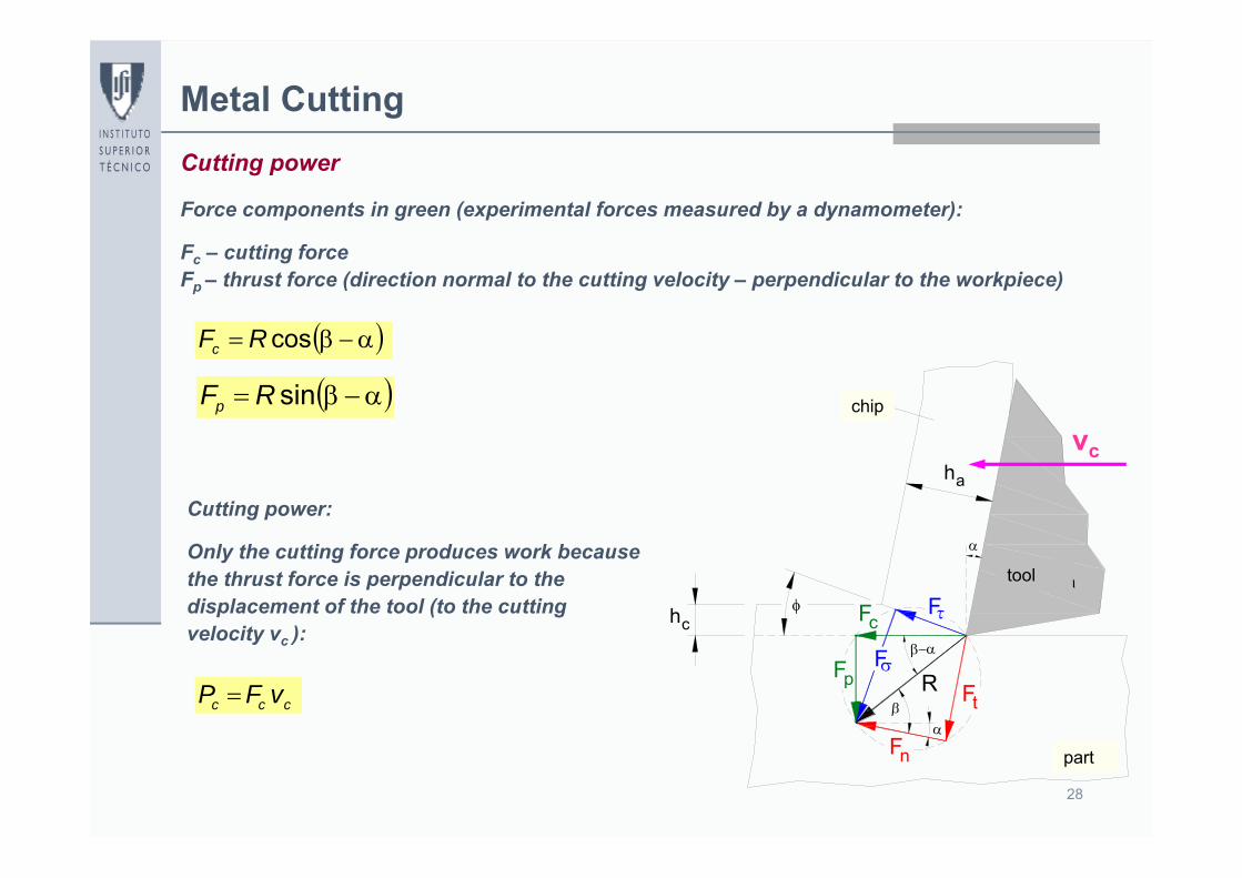
Force components in green (experimental forces measured by a dynamometer):
Fc – cutting forceFp – thrust force (direction normal to the cutting velocity – perpendicular to the workpiece)
vc
Cutting power:
Only the cutting force produces work because the thrust force is perpendicular to the displacement of the tool (to the cutting velocity vc ):
ccc vFP
chip
part
tool
29
Metal Cutting
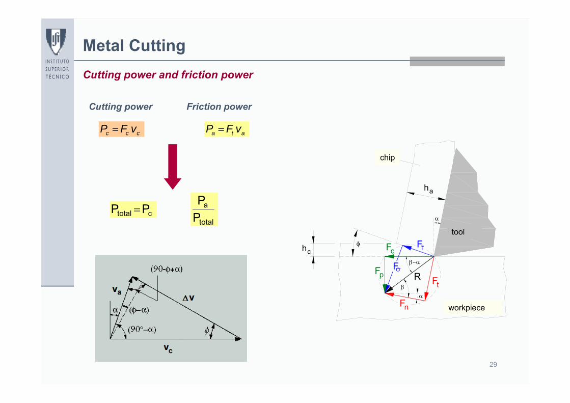
ata vFP ccc vFP
Ft
Fn
pF
cF F
F
ha
ferramenta
peça
apara
hc
R
Cutting power and friction power
Cutting power Friction power
ctotal PP total
a
PP
chip
workpiece
tool
30
Metal Cutting
cosRFc
Ft
Fn
pF
cF F
F
ha
ferramenta
peça
apara
hc
R
Specific cutting pressure
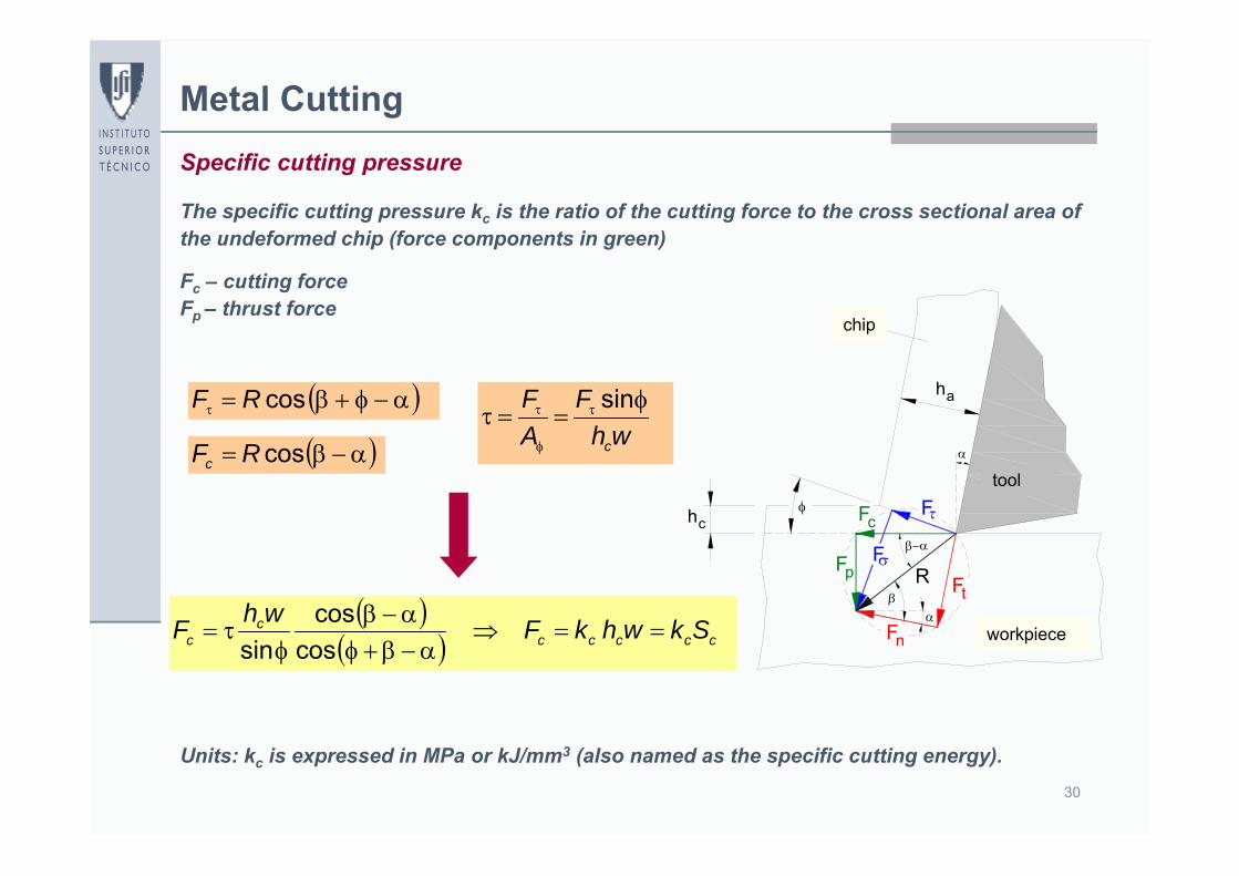
The specific cutting pressure kc is the ratio of the cutting force to the cross sectional area of the undeformed chip (force components in green)
Fc – cutting forceFp – thrust force
cosRFwh
FAF
c
sin
ccccc
cc SkwhkFwhF
coscos
sin
Units: kc is expressed in MPa or kJ/mm3 (also named as the specific cutting energy).
chip
workpiece
tool
31
Metal Cutting
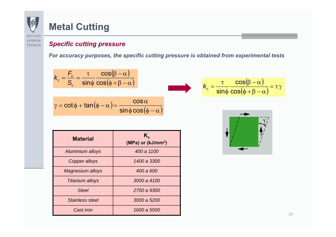
cos
cossinck
Material Kc(MPa) or (kJ/mm3)
Aluminium alloys 400 a 1100
Copper alloys 1400 a 3300
Magnesium alloys 400 a 600
Titanium alloys 3000 a 4100
Steel 2700 a 9300
Stainless steel 3000 a 5200
Cast iron 1600 a 5500
Specific cutting pressure
coscos
sinc
cc S
Fk
cossincostancot
For accuracy purposes, the specific cutting pressure is obtained from experimental tests
32
Metal Cutting
cos
sincotgarc c
a
hh
Shear-angle relationship
wh
R
whR
AF
cc
sincos
sin
cos
0coscossinsin
whR
c
0 , 0sinsincoscos wh
R
c
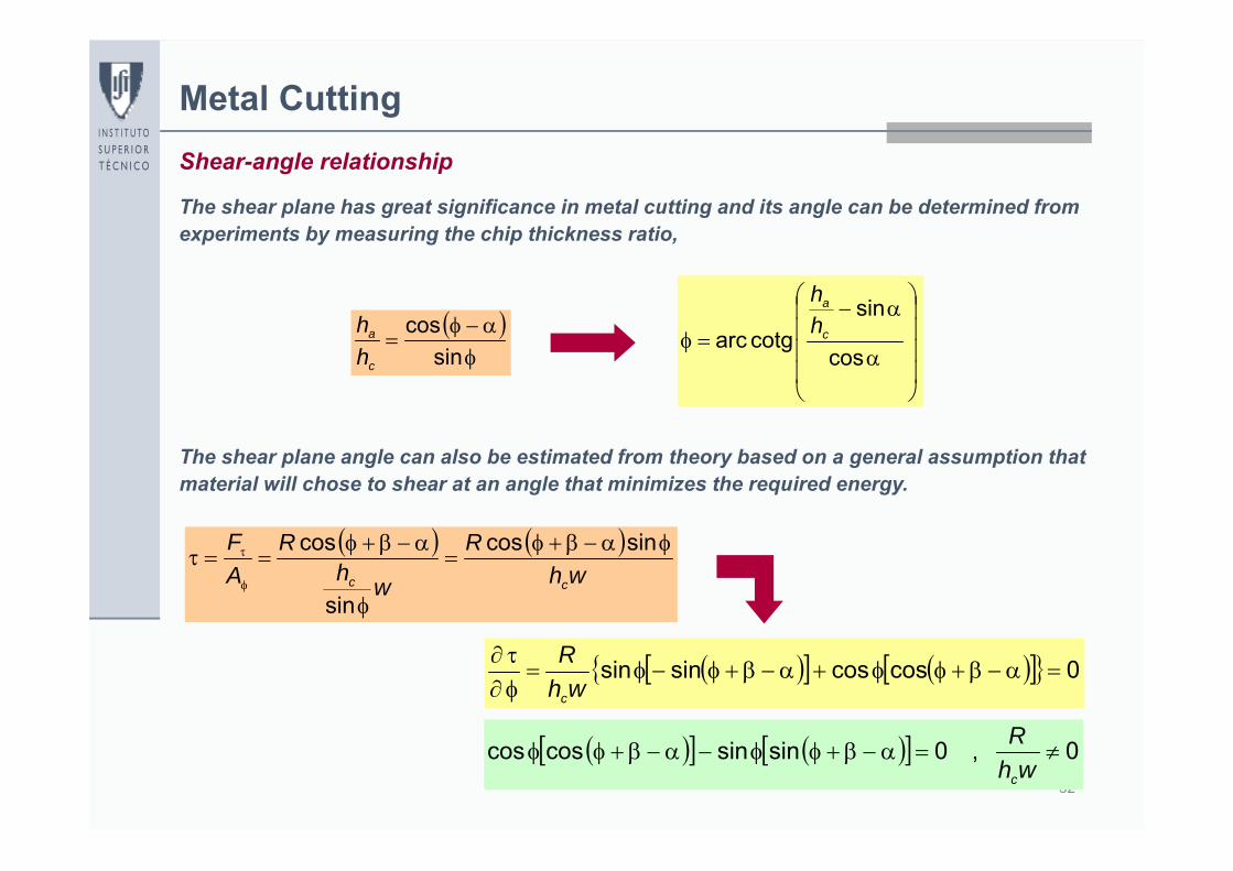
The shear plane has great significance in metal cutting and its angle can be determined from experiments by measuring the chip thickness ratio,
The shear plane angle can also be estimated from theory based on a general assumption that material will chose to shear at an angle that minimizes the required energy.
sin
cosc
a
hh
33
Metal CuttingShear-angle relationship
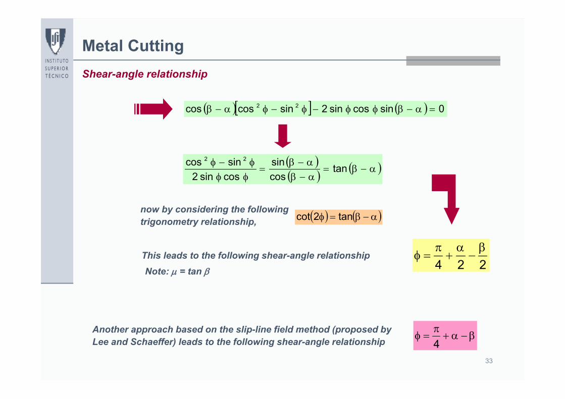
0sincossin2sincoscos 22
tan
cossin
cossin2sincos 22
tan2cot
224
now by considering the following trigonometry relationship,
This leads to the following shear-angle relationshipNote: = tan
Another approach based on the slip-line field method (proposed by Lee and Schaeffer) leads to the following shear-angle relationship
4
34
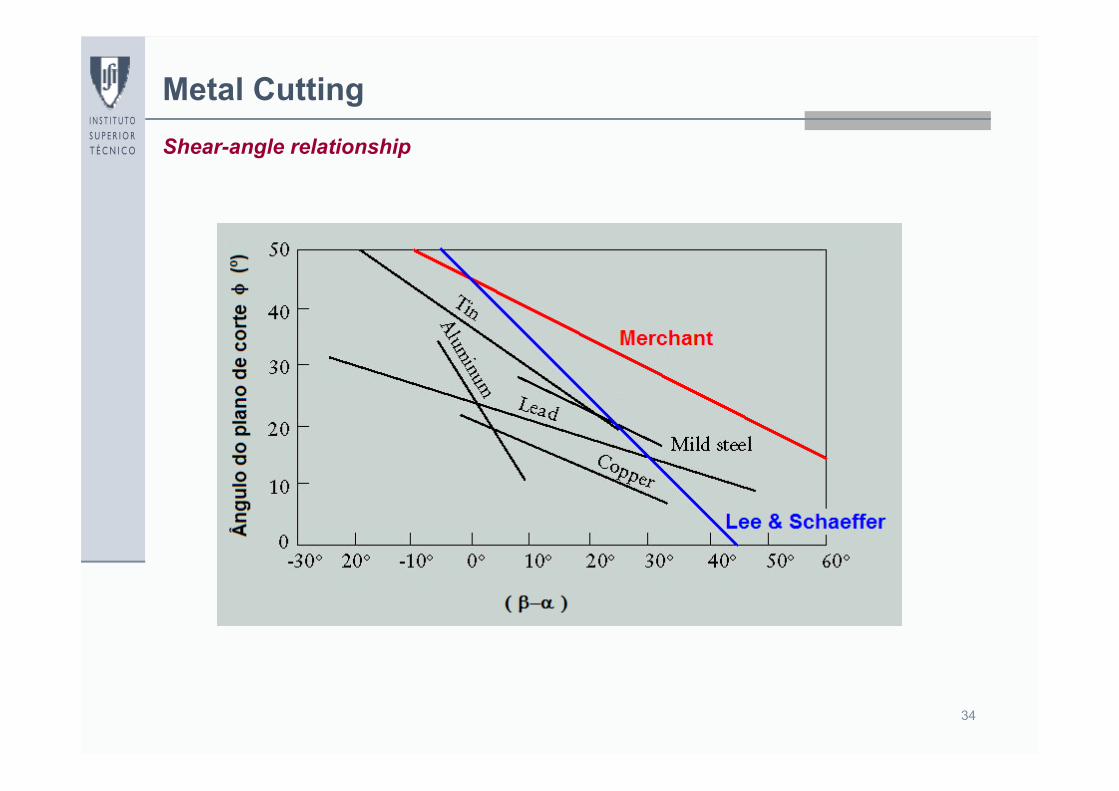
Metal CuttingShear-angle relationship
35
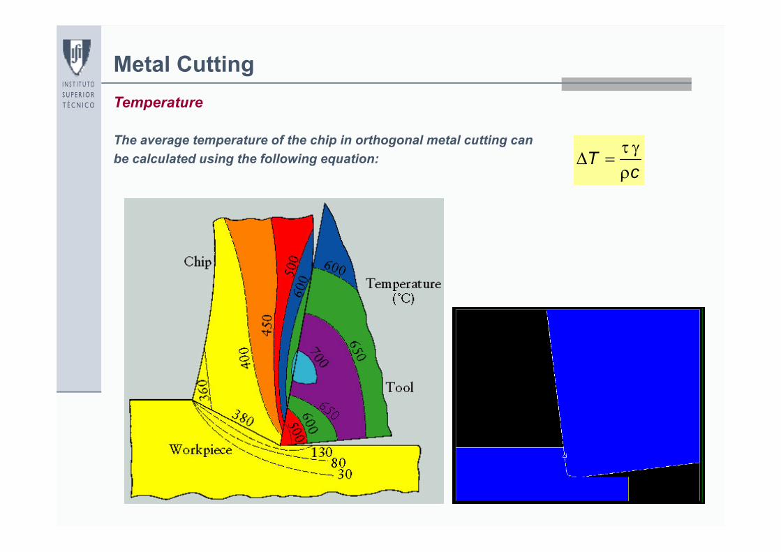
Metal CuttingTemperature
cT
The average temperature of the chip in orthogonal metal cutting can be calculated using the following equation:
36
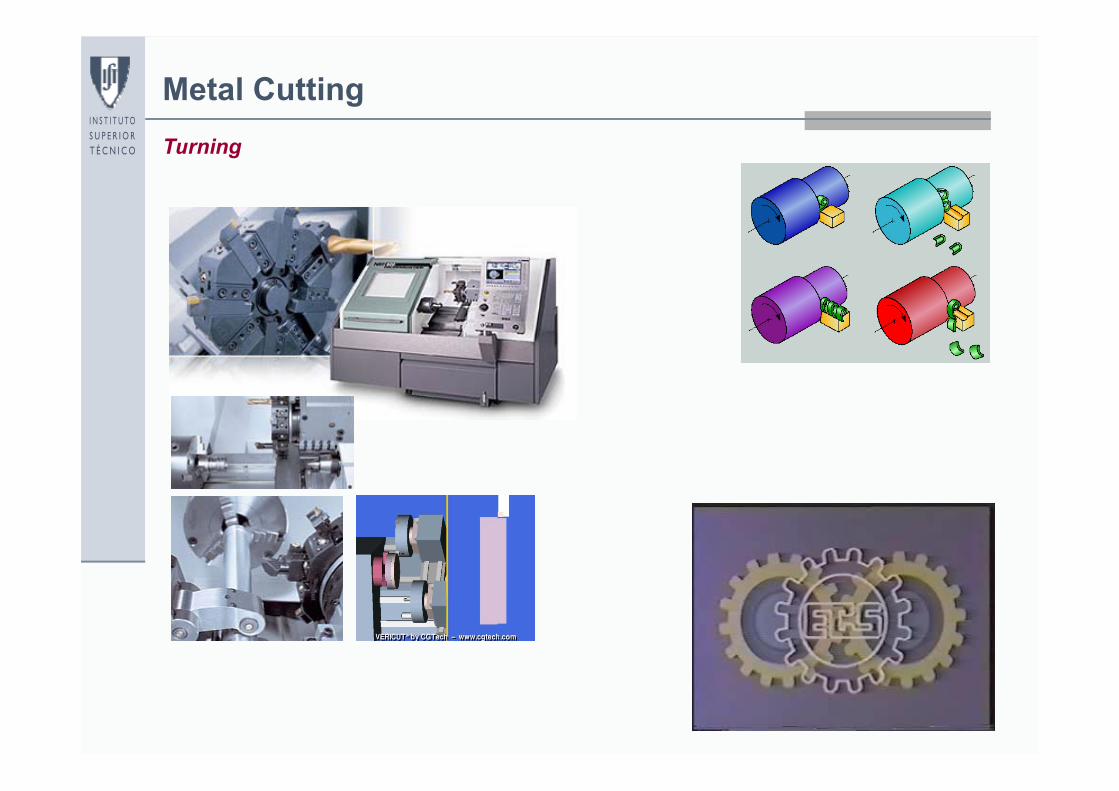
Metal CuttingTurning
37
Metal Cutting
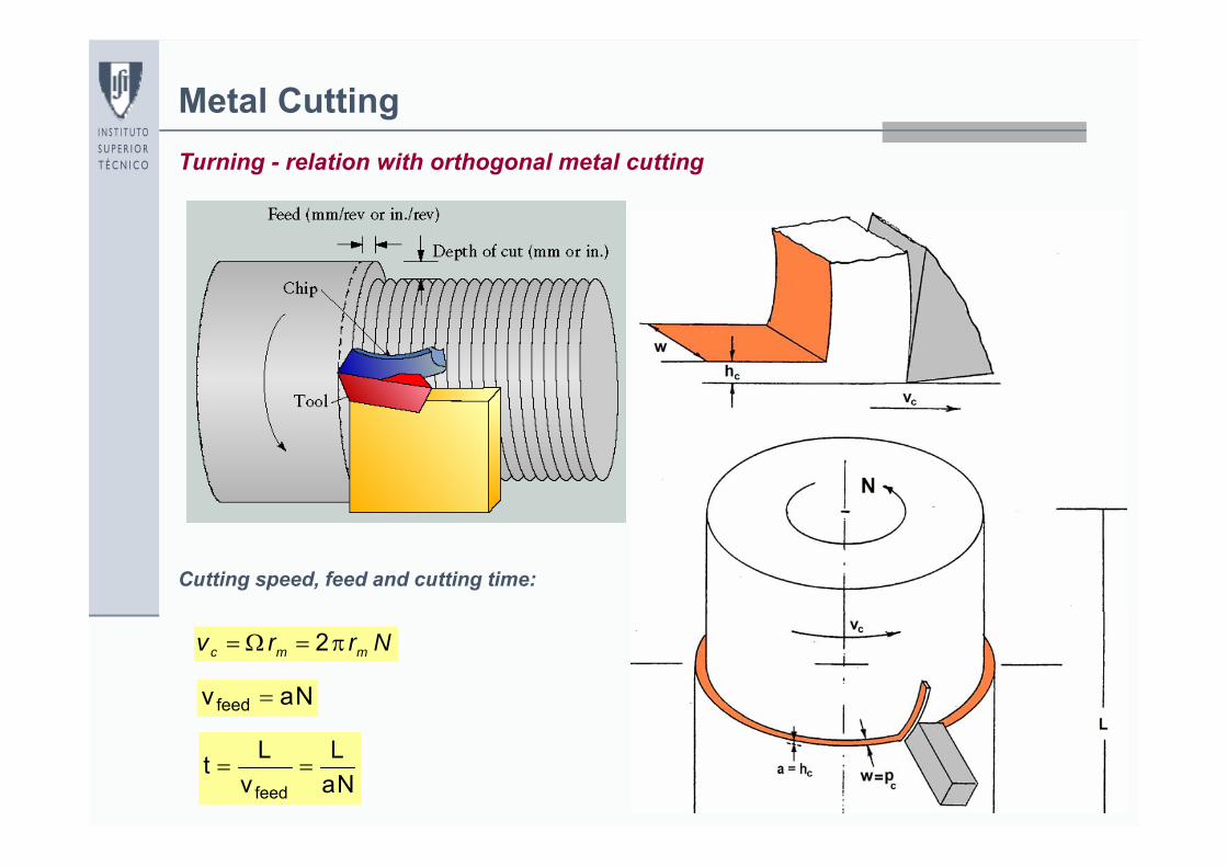
NaL
vLtfeed
Nrrv mmc 2
Turning - relation with orthogonal metal cutting
Cutting speed, feed and cutting time:
Navfeed
38
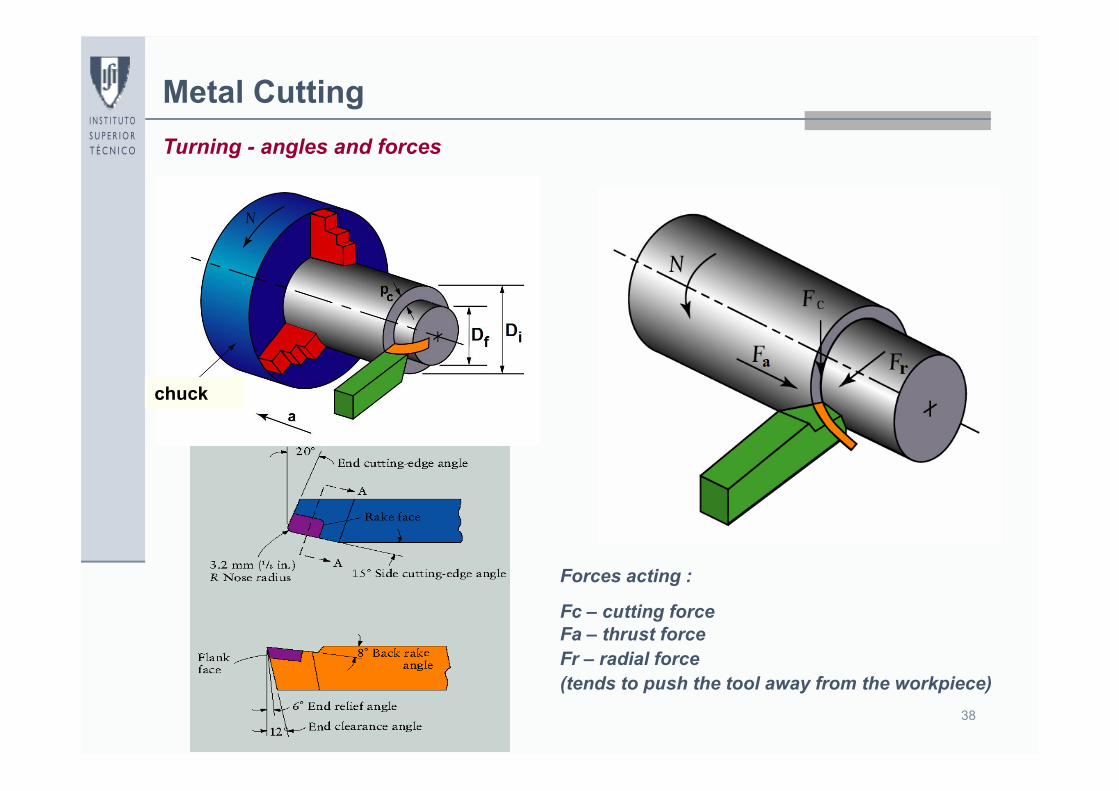
Metal CuttingTurning - angles and forces
Forces acting :
Fc – cutting forceFa – thrust forceFr – radial force (tends to push the tool away from the workpiece)
chuck

39
Metal CuttingTurning – basic operative parameters
Parameter Range of values
Cutting speed 5 mm/s a 10 m/s
Cutting speed(typical values)
50 mm/s a 3 m/s
Feed 15 m a 2.5 mm (per revolution)
Cutting depth até 25 mm
volumetric rate of material removal
1000 a 3000 mm3/s
40
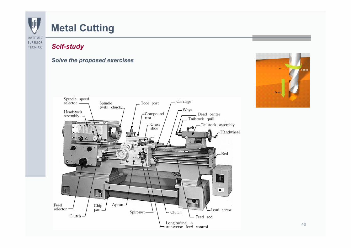
Metal CuttingSelf-study
Solve the proposed exercises