Embed Size (px)
Citation preview
Materials and Design 90 (2016) 256–265
Contents lists available at ScienceDirect
Materials and Design
j ourna l homepage: www.e lsev ie r .com/ locate / jmad
Machines and control systems for friction stir welding: A review
Nuno Mendes a, Pedro Neto b,⁎, Altino Loureiro b, António Paulo Moreira a
a Robotics and intelligent Systems Group (ROBIS) INESC-PORTO, University of Porto, Rua Dr. Roberto Frias, 378, 4200-465 Porto, Portugalb Department of Mechanical Engineering CEMUC, University of Coimbra, Polo II, Rua Luís Reis Santos, 3030-788 Coimbra, Portugal
⁎ Corresponding author.E-mail addresses: [email protected] (N. Mende
(P. Neto), [email protected] (A. Loureiro), amorei
http://dx.doi.org/10.1016/j.matdes.2015.10.1240264-1275/© 2015 Elsevier Ltd. All rights reserved.
a b s t r a c t
a r t i c l e i n f oArticle history:Received 20 February 2015Received in revised form 20 October 2015Accepted 23 October 2015Available online 26 October 2015
Keywords:Friction stir weldingMachine toolsRoboticsManufacturingControl systems
This survey presents a literature review on the machine and control systems applied in friction stir welding(FSW) with a special focus on the new trends, i.e., using robots and force control. The physical process of FSWis described and the main parameters that are relevant to select a machine and establish a control system arehighlighted. The paper reviews in detail the role of the following parameters of a given machine for FSW:force, stiffness, accuracy, sensing, decision-making and flexibility capabilities. They will be compared in termsof the different machines, namely the conventional machine tools, dedicated FSW machines, parallel kinematicrobots, and articulated robots. It is stated that articulated arm robots have enormous potentialities in the indus-trialization of the process, but they also have important limitations namely related to positional accuracy. A qual-ity FSW weld produced by a robot depends on the fine tuning of some process parameters and force/motioncontrol capabilities. Control systems can deal with these limitations. The different approaches to the control sys-tems applied in FSW are presented and their advantages/drawbacks are discussed.
© 2015 Elsevier Ltd. All rights reserved.
1. Introduction
FSWwas initially developed by Thomas et al. [1] in the early ninetiesfor joining softmetals, as aluminium alloys such as those of series 2XXXand 7XXX, which were generally considered difficult or impossible toweld using fusion welding techniques at that time. In the last decade alot of progresses have been done in FSW of metals, polymers anddissimilar materials. FSW has been used in several industries such asaeronautics, aerospace, railway, automotive and shipbuilding mainlyin welding of aluminium alloys. The FSW process takes place in thesolid-phase, at temperatures below the melting point of the material.As a result, the weld seams produced by this method are free from de-fects such as shrinkage, embrittlement, cracking or porosity. The re-duced (relatively low) welding temperature during this process makespossible lower distortion and residual stresses, enabling improvedmechanical properties. FSW is also an energy efficient process that re-quires no filler material and, in most cases, does not require the use ofa shielding gas. Furthermore, the process lacks fumes, arc flash, spatter,and pollution which are associated with most fusion welding tech-niques. This makes FSWa very attractive welding process. Conventionalwelding poses serious threats to health and safety of workers. Smokeand fumes generated by welding are the most common health risks,
s), [email protected]@fe.up.pt (A.P. Moreira).
as they are extremely toxic. These health risks are found mainly in fu-sion welding. However, as the process of FSW is a solid state process,it does not present this kind of risk. This is a topic that worries society,which can mean that in some years important restrictions can be im-posed to the most dangerous welding processes.
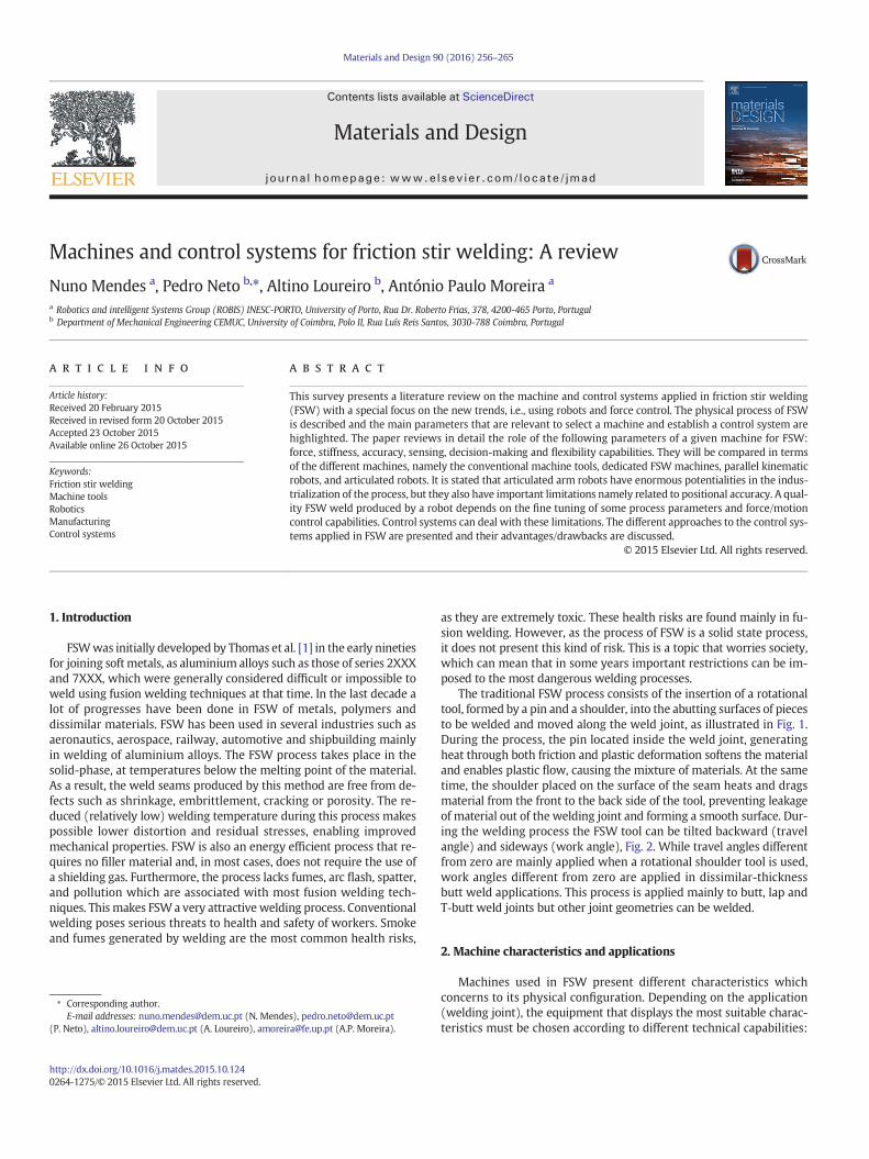
The traditional FSW process consists of the insertion of a rotationaltool, formed by a pin and a shoulder, into the abutting surfaces of piecesto be welded and moved along the weld joint, as illustrated in Fig. 1.During the process, the pin located inside the weld joint, generatingheat through both friction and plastic deformation softens the materialand enables plastic flow, causing the mixture of materials. At the sametime, the shoulder placed on the surface of the seam heats and dragsmaterial from the front to the back side of the tool, preventing leakageof material out of the welding joint and forming a smooth surface. Dur-ing the welding process the FSW tool can be tilted backward (travelangle) and sideways (work angle), Fig. 2. While travel angles differentfrom zero are mainly applied when a rotational shoulder tool is used,work angles different from zero are applied in dissimilar-thicknessbutt weld applications. This process is applied mainly to butt, lap andT-butt weld joints but other joint geometries can be welded.
2. Machine characteristics and applications
Machines used in FSW present different characteristics whichconcerns to its physical configuration. Depending on the application(welding joint), the equipment that displays the most suitable charac-teristics must be chosen according to different technical capabilities:
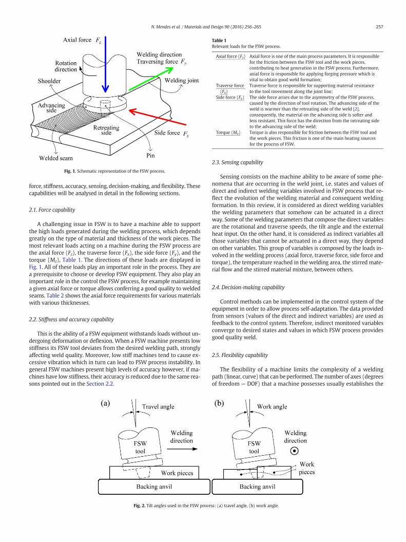
Fig. 1. Schematic representation of the FSW process.
Table 1Relevant loads for the FSW process.
Axial force (Fz) Axial force is one of the main process parameters. It is responsiblefor the friction between the FSW tool and the work pieces,contributing to heat generation in the FSW process. Furthermore,axial force is responsible for applying forging pressure which isvital to obtain good weld formation;
Traverse force(Fx)
Traverse force is responsible for supporting material resistanceto the tool movement along the joint line;
Side force (Fy) The side force arises due to the asymmetry of the FSW process,caused by the direction of tool rotation. The advancing side of theweld is warmer than the retreating side of the weld [2],consequently, the material on the advancing side is softer andless resistant. This force has the direction from the retreating sideto the advancing side of the weld;
Torque (Mz) Torque is also responsible for friction between the FSW tool andthe work pieces. This friction is one of the main heating sourcesfor the process of FSW.
257N. Mendes et al. / Materials and Design 90 (2016) 256–265
force, stiffness, accuracy, sensing, decision-making, andflexibility. Thesecapabilities will be analysed in detail in the following sections.
2.1. Force capability
A challenging issue in FSW is to have a machine able to supportthe high loads generated during the welding process, which dependsgreatly on the type of material and thickness of the work pieces. Themost relevant loads acting on a machine during the FSW process arethe axial force (Fz), the traverse force (Fx), the side force (Fy), and thetorque (Mz), Table 1. The directions of these loads are displayed inFig. 1. All of these loads play an important role in the process. They area prerequisite to choose or develop FSW equipment. They also play animportant role in the control the FSW process, for example maintaininga given axial force or torque allows conferring a good quality to weldedseams. Table 2 shows the axial force requirements for various materialswith various thicknesses.
2.2. Stiffness and accuracy capability
This is the ability of a FSW equipment withstands loads without un-dergoing deformation or deflexion. When a FSWmachine presents lowstiffness its FSW tool deviates from the desired welding path, stronglyaffecting weld quality. Moreover, low stiff machines tend to cause ex-cessive vibration which in turn can lead to FSW process instability. Ingeneral FSW machines present high levels of accuracy however, if ma-chines have low stiffness, their accuracy is reduced due to the same rea-sons pointed out in the Section 2.2.
Fig. 2. Tilt angles used in the FSW proce
2.3. Sensing capability
Sensing consists on the machine ability to be aware of some phe-nomena that are occurring in the weld joint, i.e. states and values ofdirect and indirect welding variables involved in FSW process that re-flect the evolution of the welding material and consequent weldingformation. In this review, it is considered as direct welding variablesthe welding parameters that somehow can be actuated in a directway. Some of thewelding parameters that compose the direct variablesare the rotational and traverse speeds, the tilt angle and the externalheat input. On the other hand, it is considered as indirect variables allthose variables that cannot be actuated in a direct way, they dependon other variables. This group of variables is composed by the loads in-volved in the welding process (axial force, traverse force, side force andtorque), the temperature reached in thewelding area, the stirred mate-rial flow and the stirred material mixture, between others.
2.4. Decision-making capability
Control methods can be implemented in the control system of theequipment in order to allow process self-adaptation. The data providedfrom sensors (values of the direct and indirect variables) are used asfeedback to the control system. Therefore, indirect monitored variablesconverge to desired states and values in which FSW process providesgood quality weld.
2.5. Flexibility capability
The flexibility of a machine limits the complexity of a weldingpath (linear, curve) that can be performed. The number of axes (degreesof freedom — DOF) that a machine possesses usually establishes the
ss: (a) travel angle, (b) work angle.
Table 2Parameters for FSW for different materials: thickness vs. axial force.
Material Thickness (mm) Axial force (kN) Reference
AISI 409 M 4 24 [3]AA2195-T6 6.35 13.8 [4]AA6061-T6 6.35 12.5 [4]AA7075-T6 5 8 [5]ADC12 4 6.9 [6]C11000 3.1 7 [7]Cu-DHP R240 1 7 [8]AZ31B 6 3 [9]AZ61A 6 5 [10]High nitrogen austenitic steel 2.4 20 [11]AA6082-T6/AA7075-T6
8 12 [12]
AA5083-H111/Cu-DHP R240
1 7 [13,14]
Cu/cuZn30 3 5.5 [15]Al-4.5%Cu-10%TiC 5 6 [16]AA2124-SiC 15 8.5 [17]AA6061/0–10 wt.% ZrB2 6 6 [18]AA7005/10 vol.% Al2O3 particles 7 12 [19]AA6061-T6/AlNp 6 3–7 [20]ABS 6 2 [21,22]
258 N. Mendes et al. / Materials and Design 90 (2016) 256–265
flexibility of the machine. A one-dimensional (1D) welding path is theleast complex requiring the least flexibility (smaller number of axes).The simplest version of this machine possesses just two axes. On theother hand, a two-dimensional (2D) welding path requires more flexi-bility, not only to move the FSW tool through the two directions butalso to maintain work and travel angles. A three-dimensional (3D)welding path is themost demanding in flexibility, amachine to performthe simplest 3D path must have at least five axes. In addition, in manyapplications multiple welds with multiple directions and with multipleorientations are required, which demands the required flexibility of themachine.
2.6. Applications
The choice for a specific FSW machine is dependent on differentparameters as indicated above. A major problem is related with theindustrialization of the process in general and the capacity of a givenFSW machine to produce welds in different parts. Such parts can varyin material, size, geometry, required accuracy, etc. In addition, FSWhas been used to produce welds in difficult to weld aluminium alloysand dissimilar materials. Buffa et al. report an experimental campaignto obtain T and lap joints for partswith dimensions of industrial interest(panels 300 × 200 × 3 mm) made of two different aluminium alloys(AA2024–AA7175) [23]. This technologic process is already been usedin a wide range of industries, namely aeronautics, aerospace [24], ship-building [25], railway, automotive [26], construction, electric, electronic,among others [27,28].
In aeronautics and aerospace industry several parts of aircrafts,rockets and space probes have beenmanufactured by FSW. This processis appealing because it introduces reduction of manufacturing costs andweight savings. Joining of skins to spars, ribs, and stringers are typicalapplications of FSW in these industries. The process is suitable for themanufacturing of the following parts: wings, fuselages, empennages,floor panels, aircraft landing gear doors, cryogenic fuel tanks for spacevehicles aviation fuel tanks, among others.
Shipbuilding industry makes use of FSW process for an extensiverange of applications. The FSW process can therefore be considered forwelding the following components: panels for decks, sides, bulkheadsand floors, hulls and superstructures, helicopter landing platforms, off-shore accommodation, masts and booms, and refrigeration plants.
Applications of FSW in the railway industry include themanufactur-ing of the following components: high speed trains; rolling stock of
railways, underground carriages, trams, railway tankers and goodswag-gons, container bodies, roof and floor panels.
The FSW process is currently being used inmanufacturing of severalautomotive mechanical components. The process is suitable to producedifferentwelds, long, straight or curvedwelds. The process has been ap-plied to produce the following components: trailer beams, cabins anddoors, spoilers, front walls, closed body or curtains, drop side walls,frames, floors, bumpers, chassis, fuel and air containers, engine parts,air suspension systems, drive shafts, engine and chassis cradles.
FSW has also been applied in construction industry, namely in theconstruction of aluminium bridges, facade panels (made from alumini-um, copper or titanium),window frames, aluminium pipelines and heatexchangers. Moreover, FSW has expanded in the last few years in otherapplication fields like the electrical (e.g. motor housings), oil and gas(e.g. land and offshore pipelines), and nuclear industry.
3. FSW machines
Three kinds of machines are reported in literature as viable to per-form FSW. These machines are:
- Conventional machine tools such as milling machines [29,30];- Dedicated FSWmachines or custom-built machines [31]- Industrial robots [32–34].
3.1. Conventional machine tools
The process of FSW is similar in terms of principle of operation of theequipment to other technological manufacturing processes such as ma-chining, deburring, grinding and drilling. Basically, all of these processesconsist in moving a rotating tool through a work piece, producing drag-ging ofmaterial which constitutes thework piece. Thus, it is plausible toassume that a conventionalmachine tool, such as amillingmachine, canbe used to perform FSW [35]. However, the loads generated during theFSW process gain more relevance when this equipment is used. Theloads involved in FSWare higher than the loads generated in themillingprocess [36,37]. For this reason, conventional machine tools have to bestrengthened in order to increase their load and stiffness capabilities.Thus, there are potential opportunities to modify existing equipmentto perform FSW. The machine modifications can be made on severallevels: structural, flexibility, decision-making and sensing [38]. Thestructural modifications are performed in order to make the equipmentmore robust (some parts of equipment can be replaced such as ways,guides, rails, motors, spindles, etc.). The flexibility can be increased bythe introduction of additional motors that provide additional degreesof freedom to the equipment. Owing to the high loads involved in theFSWprocess, themajority of the solutions have implemented force con-trol to prevent equipment damage and ensure human safety and toachieve good weld quality. The decision-making of the equipment canstill be improved providing movement in more directions at the sametime. Besides that, the machine can be equipped with multiple sensorsto collect different information whichwill be used to control the equip-ment through an embedded control solution.
Thesemachines are very popular due to the fact that they arewidelyused in industry for machining purposes, which is one of themost com-mon technologic processes used in industry. Therefore, the existence ofthis kind of equipment in industry is guaranteed as well as knowledgeto operate it. In FSW the use ofmodifiedmachine tools is recommendedfor:
- Prototyping and small series production of:- Welding long or small work pieces;- Welding thick or thin work pieces;
- Applications where high stiffness is required;- Single- or multi-axis applications.
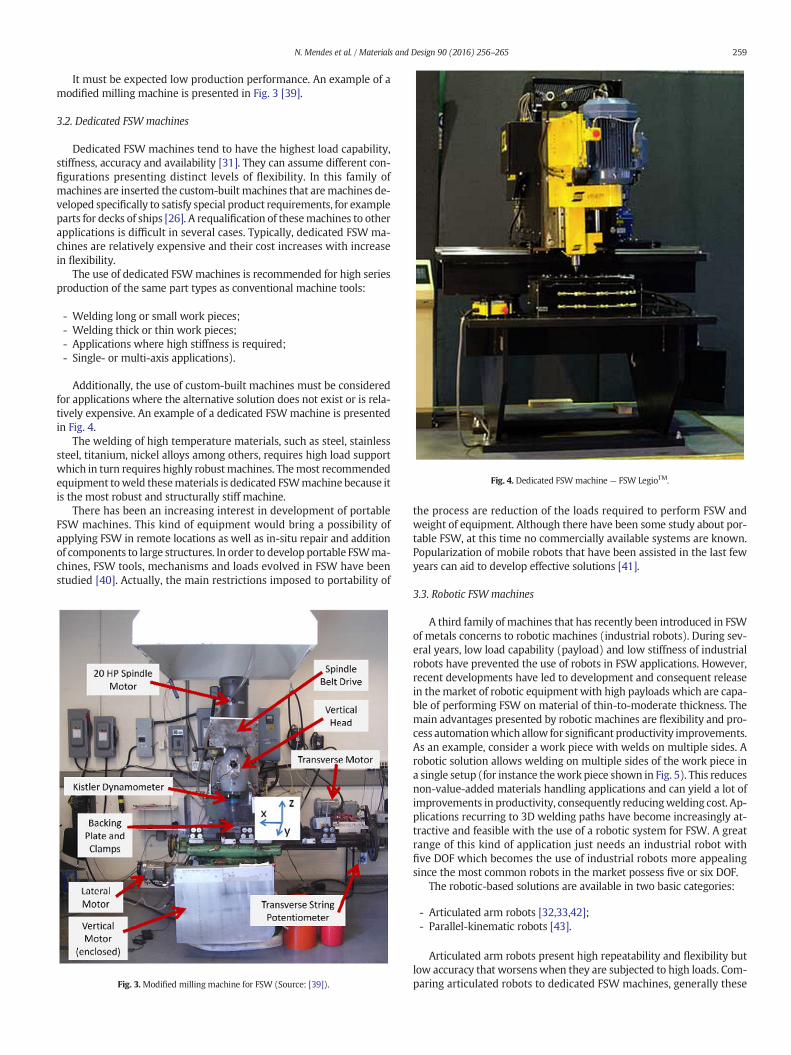
Fig. 4. Dedicated FSWmachine — FSW LegioTM.
259N. Mendes et al. / Materials and Design 90 (2016) 256–265
It must be expected low production performance. An example of amodified milling machine is presented in Fig. 3 [39].
3.2. Dedicated FSW machines
Dedicated FSW machines tend to have the highest load capability,stiffness, accuracy and availability [31]. They can assume different con-figurations presenting distinct levels of flexibility. In this family ofmachines are inserted the custom-built machines that aremachines de-veloped specifically to satisfy special product requirements, for exampleparts for decks of ships [26]. A requalification of thesemachines to otherapplications is difficult in several cases. Typically, dedicated FSW ma-chines are relatively expensive and their cost increases with increasein flexibility.
The use of dedicated FSWmachines is recommended for high seriesproduction of the same part types as conventional machine tools:
- Welding long or small work pieces;- Welding thick or thin work pieces;- Applications where high stiffness is required;- Single- or multi-axis applications).
Additionally, the use of custom-built machines must be consideredfor applications where the alternative solution does not exist or is rela-tively expensive. An example of a dedicated FSWmachine is presentedin Fig. 4.
The welding of high temperature materials, such as steel, stainlesssteel, titanium, nickel alloys among others, requires high load supportwhich in turn requires highly robustmachines. Themost recommendedequipment toweld thesematerials is dedicated FSWmachine because itis the most robust and structurally stiff machine.
There has been an increasing interest in development of portableFSW machines. This kind of equipment would bring a possibility ofapplying FSW in remote locations as well as in-situ repair and additionof components to large structures. In order to develop portable FSWma-chines, FSW tools, mechanisms and loads evolved in FSW have beenstudied [40]. Actually, the main restrictions imposed to portability of
Fig. 3. Modified milling machine for FSW (Source: [39]).
the process are reduction of the loads required to perform FSW andweight of equipment. Although there have been some study about por-table FSW, at this time no commercially available systems are known.Popularization of mobile robots that have been assisted in the last fewyears can aid to develop effective solutions [41].
3.3. Robotic FSW machines
A third family of machines that has recently been introduced in FSWof metals concerns to robotic machines (industrial robots). During sev-eral years, low load capability (payload) and low stiffness of industrialrobots have prevented the use of robots in FSW applications. However,recent developments have led to development and consequent releasein themarket of robotic equipment with high payloads which are capa-ble of performing FSW on material of thin-to-moderate thickness. Themain advantages presented by robotic machines are flexibility and pro-cess automationwhich allow for significant productivity improvements.As an example, consider a work piece with welds on multiple sides. Arobotic solution allows welding on multiple sides of the work piece ina single setup (for instance thework piece shown in Fig. 5). This reducesnon-value-added materials handling applications and can yield a lot ofimprovements in productivity, consequently reducingwelding cost. Ap-plications recurring to 3D welding paths have become increasingly at-tractive and feasible with the use of a robotic system for FSW. A greatrange of this kind of application just needs an industrial robot withfive DOF which becomes the use of industrial robots more appealingsince the most common robots in the market possess five or six DOF.
The robotic-based solutions are available in two basic categories:
- Articulated arm robots [32,33,42];- Parallel-kinematic robots [43].
Articulated arm robots present high repeatability and flexibility butlow accuracy that worsenswhen they are subjected to high loads. Com-paring articulated robots to dedicated FSW machines, generally these
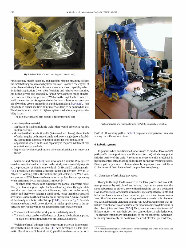
Fig. 6. Articulated arm robot performing FSW at the University of Coimbra.
1 A robot is said compliant when it is not completely rigid and when it can sense andcontrol the forces it applies to work pieces.
Fig. 5. Robotic FSW of a multi welding part (Source: [44]).
260 N. Mendes et al. / Materials and Design 90 (2016) 256–265
robots display higher flexibility and decision-making capability besidesthe fact that they are remarkably lower in cost. However, these types ofrobots have relatively low stiffness and moderate load capability whichlimit their application. Given their flexibility and relative low cost, theycan be the lowest-cost solution by far but have a limited range of mate-rials on which they can perform FSW due to the high loads required toweld somematerials. As a general rule, themost robust robots are capa-ble of welding up to 6 (mm) thick aluminiummaterial [42,45,46]. Theircapability in higher-melting-point materials tend to be somewhat less.The drawbacks are related to high compliance, which cause process sta-bility issues.
The use of articulated arm robots is recommended for:
- relatively thin material;- applications having multiple welds that would otherwise requiremultiple setups;
- dissimilar-thickness butt welds (tailor-welded blanks), these kindsof welds require both a travel angle and awork angle (more flexibil-ity is required). Robots are ideal solutions for this application;
- applications where multi-axis capability is required (different toolorientations are needed);
- higherwork volume applicationswhere productivity is an importantfactor.
Marcotte and Abeele [42] have developed a robotic FSW systembased on an articulated arm robot. In this studywas successfully report-ed the production of aluminiumwelds of 1D, 2D and 3Dwelding paths.Fig. 6 presents an articulated arm robot capable to perform FSW of 1D,2D and 3D welding paths. The friction stir spot welding (FSSW), a vari-ant process of FSW, have also been reported as feasible and appealingwhen performed by an articulated arm robot [47].
The other basic robotic configuration is the parallel-kinematic robot.This type of robot support higher loads andhave significantly higher stiff-ness than an articulated arm robot. However, their cost can be notablyhigher, and their work volume is significantly lesser than the articulatedarm robots, aswell as the allowed range of orientation. A typical exampleof this family of robots is the Tricept [19,48], shown in Fig. 7. Parallel-kinematic robots should be considered in similar applications to the ar-ticulated arm robots with the following particular characteristics:
- The work volume of the work pieces is relatively small;- The work piece can be welded near or close to the horizontal plane;- The load or stiffness requirements are somewhat higher.
Welding of small thinness high temperature materials is also possi-ble with this kind of robot. Shi et al. [49] have developed a 3-PRS (Pris-matic, Revolute and Spherical joint) parallel mechanism to perform
FSW of 3D welding paths. Table 3 displays a comparative analysisamong the different machines.
4. Robotic systems
In general, when an articulated robot is used to produce FSW, robot'spaths suffer some positional modifications (errors) which may put atrisk the quality of the weld. A solution to overcome this drawback isthe tight control of loads acting on the robot during thewelding process.Diverse path adjustment techniques have beenproposed successfully sofar but none of them have solved the problem completely.
4.1. Limitations of articulated arm robots
Owing to the high loads involved in the FSW process and low stiff-ness presented by articulated arm robots, they cannot guarantee thesame robustness as either a conventional machine tool or a dedicatedFSW machine [28]. Articulated arm robots are composed by joints andlinks that have associated servomotors, gearboxes and transmissionaxes. All of these elements are subjugated to non-predictable phenom-ena such as backlash, vibration, bearing run-out, betweenothers that at-tribute compliance1 to articulated arm robots leading to deflexions inthe robot's joints and links [50,51]. Thus, encoders mounted to robots'linkage motors to read their position cannot detect such deflexions.The encoder readings are then fed back to the robots control system de-termining erroneously the position of their end-effectors (i.e. FSW tool).
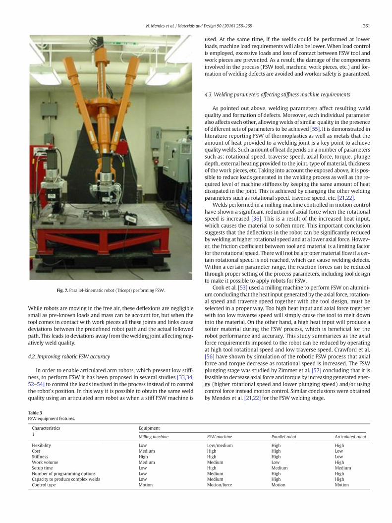
Fig. 7. Parallel-kinematic robot (Tricept) performing FSW.
261N. Mendes et al. / Materials and Design 90 (2016) 256–265
While robots are moving in the free air, these deflexions are negligiblesmall as pre-known loads and mass can be account for, but when thetool comes in contact with work pieces all these joints and links causedeviations between the predefined robot path and the actual followedpath. This leads to deviations away from thewelding joint affecting neg-atively weld quality.
4.2. Improving robotic FSW accuracy
In order to enable articulated arm robots, which present low stiff-ness, to perform FSW it has been proposed in several studies [33,34,52–54] to control the loads involved in the process instead of to controlthe robot's position. In this way it is possible to obtain the same weldquality using an articulated arm robot as when a stiff FSW machine is
Table 3FSW equipment features.
Characteristics↓
Equipment
Milling machine
Flexibility LowCost MediumStiffness HighWork volume MediumSetup time LowNumber of programming options LowCapacity to produce complex welds LowControl type Motion
used. At the same time, if the welds could be performed at lowerloads, machine load requirements will also be lower.When load controlis employed, excessive loads and loss of contact between FSW tool andwork pieces are prevented. As a result, the damage of the componentsinvolved in the process (FSW tool, machine, work pieces, etc.) and for-mation of welding defects are avoided and worker safety is guaranteed.
4.3. Welding parameters affecting stiffness machine requirements
As pointed out above, welding parameters affect resulting weldquality and formation of defects. Moreover, each individual parameteralso affects each other, allowingwelds of similar quality in the presenceof different sets of parameters to be achieved [55]. It is demonstrated inliterature reporting FSW of thermoplastics as well as metals that theamount of heat provided to a welding joint is a key point to achievequalitywelds. Such amount of heat depends on a number of parameterssuch as: rotational speed, traverse speed, axial force, torque, plungedepth, external heating provided to the joint, type of material, thicknessof thework pieces, etc. Taking into account the exposed above, it is pos-sible to reduce loads generated in the welding process as well as the re-quired level of machine stiffness by keeping the same amount of heatdissipated in the joint. This is achieved by changing the other weldingparameters such as rotational speed, traverse speed, etc. [21,22].
Welds performed in a milling machine controlled in motion controlhave shown a significant reduction of axial force when the rotationalspeed is increased [36]. This is a result of the increased heat input,which causes the material to soften more. This important conclusionsuggests that the deflections in the robot can be significantly reducedbywelding at higher rotational speed and at a lower axial force. Howev-er, the friction coefficient between tool and material is a limiting factorfor the rotational speed. Therewill not be a propermaterialflow if a cer-tain rotational speed is not reached, which can cause welding defects.Within a certain parameter range, the reaction forces can be reducedthrough proper setting of the process parameters, including tool designto make it possible to apply robots for FSW.
Cook et al. [53] used a milling machine to perform FSW on alumini-um concluding that theheat input generated by the axial force, rotation-al speed and traverse speed together with the tool design, must beselected in a proper way. Too high heat input and axial force togetherwith too low traverse speed will simply cause the tool to melt downinto the material. On the other hand, a high heat input will produce asofter material during the FSW process, which is beneficial for therobot performance and accuracy. This study summarizes as the axialforce requirements imposed to the robot can be reduced by operatingat high tool rotational speed and low traverse speed. Crawford et al.[56] have shown by simulation of the robotic FSW process that axialforce and torque decrease as rotational speed is increased. The FSWplunging stage was studied by Zimmer et al. [57] concluding that it isfeasible to decrease axial force and torque by increasing generated ener-gy (higher rotational speed and lower plunging speed) and/or usingcontrol force insteadmotion control. Similar conclusions were obtainedby Mendes et al. [21,22] for the FSW welding stage.
FSW machine Parallel robot Articulated robot
Low/medium High HighHigh High LowHigh High LowMedium Low HighHigh Medium MediumMedium High HighMedium High HighMotion/force Motion Motion
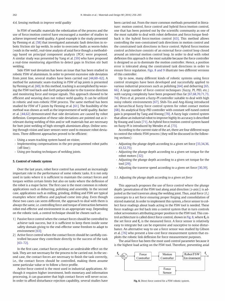
Fig. 8. Direct force control for a FSW robotic system.
262 N. Mendes et al. / Materials and Design 90 (2016) 256–265
4.4. Sensing methods to improve weld quality
In FSW of metallic materials the robotization of the process and theuse of force/motion control have encouraged a number of studies toachieve improved weld quality. A good example is the study presentedby Fleming et al. [58] that investigated automatic fault detection in ro-botic friction stir lap welds. In order to overcome faults as worm-holes(voids in theweld), real-time analysis of axial force though amethodol-ogy based on principal component analysis (PCA) were proposed.A similar study was presented by Yang et al. [59] who have proposeda real-time monitoring algorithm to detect gaps in friction stir buttwelding.
Side FSW tool deviation has been an issue that has been studied inrobotic FSW of aluminium. In order to prevent excessive side deviationfrom joint line, several studies have been carried out [44,60–62]. Amethod for automatic seam-tracking in FSW of lap joints is presentedby Fleming et al. [60]. In thismethod, tracking is accomplished byweav-ing the FSW tool back-and-forth perpendicular to the traverse directionand monitoring force and torque signals. This approach showed to beefficient and weaving does not reduce weld quality. It can be utilizedin robotic and non-robotic FSW process. The same method has beenstudied for FSW of T-joints by Fleming et al. [61]. The feasibility of themethod was shown as well as the improvement of weld quality. Backeret al. [44,62] demonstrated that side deviations are caused by robotdeflexion. Compensation of these side deviations are pointed out as ir-relevant during welding of thin and/or soft materials but are necessaryfor butt-joint welding of high-strength aluminium alloys. Online sens-ing through vision and laser sensors were used to measure robot devia-tions. Three different approaches proved to be efficient:
- Using a seam-tracking system based on vision;- Implementing compensations in the pre-programmed robot paths(off-line);
- Using pre-heating techniques of welding joints.
5. Control of robotic system
Over the last years, robot force control has assumed an increasinglyimportant role in the performance of some robotic tasks. It is not onlyused in tasks where it is sufficient to maintain the contact forces andtorques within certain limits but also on tasks where the deflexion ofthe robot is a major factor. The first case is the most common in roboticapplications such as deburring, polishing and assembly. In the secondcase, applications such as milling, grinding, drilling and FSW are typicalexamples where stiffness and payload come into play. Even thoughthese two cases can seem different, the approach to deal with them isalways the same, i.e. controlling force and torque of interaction betweenrobot end-effector and environment in an appropriate way. Dependingon the robotic task, a control technique should be chosen such as:
1) Passive force control when the contact forces should be controlled toachieve task success, but it is sufficient to keep them inside somesafety domain giving to the end-effector some freedom to adapt toenvironment [63];
2) Active force control when the contact forces should be carefully con-trolled because they contribute directly to the success of the task[63–72].
In the first case, contact forces produce an undesirable effect on thetask. They are not necessary for the process to be carried out. In the sec-ond case, the contact forces are necessary to finish the task correctly,i.e., the contact forces should be controlled, making them assumesome particular value or to follow a force profile.
Active force control is the most used in industrial applications. Al-though it requires higher investment, both monetary and informationprocessing, it can guarantee that high contact forces will never occur.In order to afford disturbance rejection capability, several studies have
been carried out. From the more common methods presented in litera-ture: motion control, force control and hybrid force/motion control,one that has been pointed out by the scientific community as one ofthe most suitable to deal with robot deflexion and force/torque feed-back is the hybrid force/motion control [63]. This method allowscontrolling the non-constrained task directions in motion control andthe constrained task directions in force control. Hybrid force/motioncontrol architecture consists of an external force control loop closedaround an internal motion control loop. In order to deal with robotdeflexion this approach is themost suitable because the force controlleris designed so as to dominate the motion controller. Hence, a positionerror is tolerated along the constrained task directions in order toensure force regulation. Figs. 8 and 9 illustrate two different versionsof this controller.
Up to now, many different kinds of robotic systems using forcecontrol strategies have been developed and successfully applied tovarious industrial processes such as polishing [64] and deburring [65,66]. A large number of force control techniques (fuzzy, PI, PID, etc.)with varying complexity have been proposed thus far [67,68,70,71,73,74]. Pires et al. present a fuzzy-PI controller suitable to deal with highnoisy robotic environments [67]. Shih-Tin and Ang-Kiong introducedan hierarchical fuzzy force control system for robot contact motion[68]. An analytical fizzy-PID controller with constant self-tuned controlgain is proposed by Tang and Kwong [70]. A fuzzy logic control systemthat allow an industrial robot to improve highly its accuracy is describedby Kwang and Louis [71]. An hybrid force/motion control system basedon fuzzy-PI is introduced by Mendes et al. [73].
According to the current state of the art, there are four differentwaysto control the robotic FSWprocess (theywill be discussed in the follow-ing sections):
- Adjusting the plunge depth according to a given set force [33,34,36,43,52,75];
- Adjusting the plunge depth according to a given set torque for therobot motors [32];
- Adjusting the plunge depth according to a given set torque for thetool [29];
- Adjusting the traverse speed according to a given set force [30,39].
5.1. Adjusting the plunge depth according to a given set force
This approach proposes the use of force control where the plungedepth (penetration of the FSW tool along axial direction (z-axis)) is ad-justed as the tool traverses along thewelding joint. Thus, axial force (Fz)converges to a set force ensuring proper forging and consolidation ofstirredmaterial. In order to implement this system, a force sensor to col-lect force readings about loads acting in the FSW tool is needed. Theseforce readings are fed back into a control system that in turn controlsrobot servomotors attributing proper position to the FSW tool. This con-trol architecture is called direct force control, shown in Fig. 8, where fd isthe set force and fe is the measured force. A force sensor is relativelyeasy to integrate but can be expensive and susceptive to noise distur-bance. An alternative way to use a force sensor was studied by Gibsonet al. [76] who present a low-cost force measurement system that ex-ploits the robotic link deflexion for force measurement purposes.
The axial force has been the most used control parameter because itis the highest load acting on the FSW tool. Therefore, preventing axial
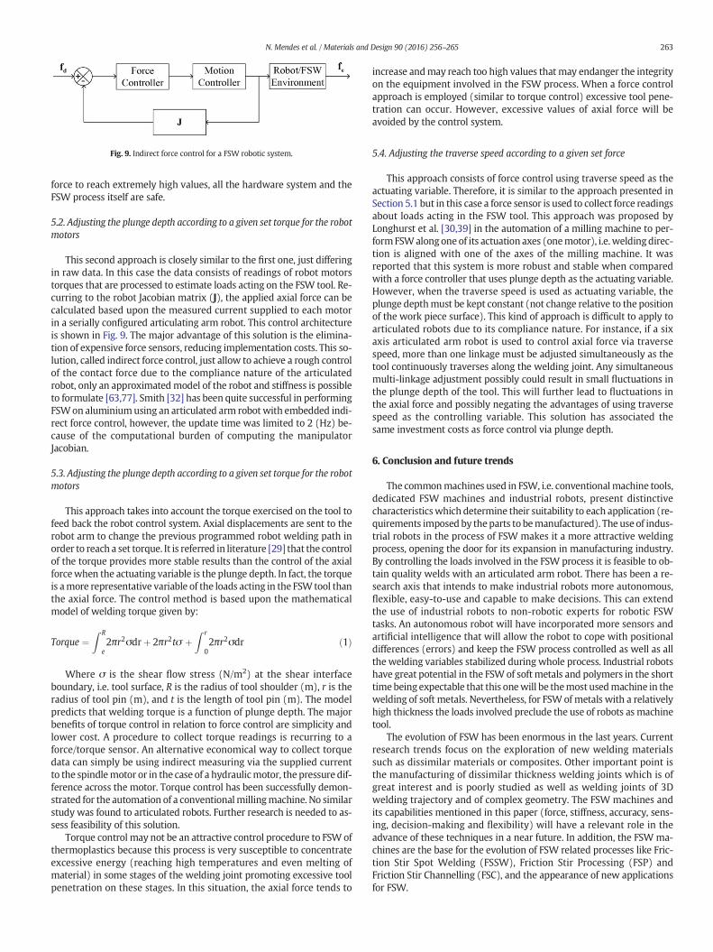
Fig. 9. Indirect force control for a FSW robotic system.
263N. Mendes et al. / Materials and Design 90 (2016) 256–265
force to reach extremely high values, all the hardware system and theFSW process itself are safe.
5.2. Adjusting the plunge depth according to a given set torque for the robotmotors
This second approach is closely similar to the first one, just differingin raw data. In this case the data consists of readings of robot motorstorques that are processed to estimate loads acting on the FSW tool. Re-curring to the robot Jacobian matrix (J), the applied axial force can becalculated based upon the measured current supplied to each motorin a serially configured articulating arm robot. This control architectureis shown in Fig. 9. The major advantage of this solution is the elimina-tion of expensive force sensors, reducing implementation costs. This so-lution, called indirect force control, just allow to achieve a rough controlof the contact force due to the compliance nature of the articulatedrobot, only an approximatedmodel of the robot and stiffness is possibleto formulate [63,77]. Smith [32] has been quite successful in performingFSWon aluminiumusing an articulated arm robot with embedded indi-rect force control, however, the update time was limited to 2 (Hz) be-cause of the computational burden of computing the manipulatorJacobian.
5.3. Adjusting the plunge depth according to a given set torque for the robotmotors
This approach takes into account the torque exercised on the tool tofeed back the robot control system. Axial displacements are sent to therobot arm to change the previous programmed robot welding path inorder to reach a set torque. It is referred in literature [29] that the controlof the torque provides more stable results than the control of the axialforcewhen the actuating variable is the plunge depth. In fact, the torqueis amore representative variable of the loads acting in the FSW tool thanthe axial force. The control method is based upon the mathematicalmodel of welding torque given by:
Torque ¼Z R
e2πr2σdrþ 2πr2tσ þ
Z r
02πr2σdr ð1Þ
Where σ is the shear flow stress (N/m2) at the shear interfaceboundary, i.e. tool surface, R is the radius of tool shoulder (m), r is theradius of tool pin (m), and t is the length of tool pin (m). The modelpredicts that welding torque is a function of plunge depth. The majorbenefits of torque control in relation to force control are simplicity andlower cost. A procedure to collect torque readings is recurring to aforce/torque sensor. An alternative economical way to collect torquedata can simply be using indirect measuring via the supplied currentto the spindlemotor or in the case of a hydraulicmotor, the pressure dif-ference across the motor. Torque control has been successfully demon-strated for the automation of a conventionalmillingmachine. No similarstudy was found to articulated robots. Further research is needed to as-sess feasibility of this solution.
Torque control may not be an attractive control procedure to FSW ofthermoplastics because this process is very susceptible to concentrateexcessive energy (reaching high temperatures and even melting ofmaterial) in some stages of the welding joint promoting excessive toolpenetration on these stages. In this situation, the axial force tends to
increase andmay reach too high values that may endanger the integrityon the equipment involved in the FSW process. When a force controlapproach is employed (similar to torque control) excessive tool pene-tration can occur. However, excessive values of axial force will beavoided by the control system.
5.4. Adjusting the traverse speed according to a given set force
This approach consists of force control using traverse speed as theactuating variable. Therefore, it is similar to the approach presented inSection 5.1 but in this case a force sensor is used to collect force readingsabout loads acting in the FSW tool. This approach was proposed byLonghurst et al. [30,39] in the automation of a milling machine to per-formFSWalongone of its actuation axes (onemotor), i.e. weldingdirec-tion is aligned with one of the axes of the milling machine. It wasreported that this system is more robust and stable when comparedwith a force controller that uses plunge depth as the actuating variable.However, when the traverse speed is used as actuating variable, theplunge depthmust be kept constant (not change relative to the positionof the work piece surface). This kind of approach is difficult to apply toarticulated robots due to its compliance nature. For instance, if a sixaxis articulated arm robot is used to control axial force via traversespeed, more than one linkage must be adjusted simultaneously as thetool continuously traverses along the welding joint. Any simultaneousmulti-linkage adjustment possibly could result in small fluctuations inthe plunge depth of the tool. This will further lead to fluctuations inthe axial force and possibly negating the advantages of using traversespeed as the controlling variable. This solution has associated thesame investment costs as force control via plunge depth.
6. Conclusion and future trends
The commonmachines used in FSW, i.e. conventionalmachine tools,dedicated FSW machines and industrial robots, present distinctivecharacteristicswhich determine their suitability to each application (re-quirements imposed by theparts to bemanufactured). The use of indus-trial robots in the process of FSW makes it a more attractive weldingprocess, opening the door for its expansion in manufacturing industry.By controlling the loads involved in the FSW process it is feasible to ob-tain quality welds with an articulated arm robot. There has been a re-search axis that intends to make industrial robots more autonomous,flexible, easy-to-use and capable to make decisions. This can extendthe use of industrial robots to non-robotic experts for robotic FSWtasks. An autonomous robot will have incorporated more sensors andartificial intelligence that will allow the robot to cope with positionaldifferences (errors) and keep the FSW process controlled as well as allthe welding variables stabilized during whole process. Industrial robotshave great potential in the FSW of softmetals and polymers in the shorttimebeing expectable that this onewill be themost usedmachine in thewelding of soft metals. Nevertheless, for FSW of metals with a relativelyhigh thickness the loads involved preclude the use of robots as machinetool.
The evolution of FSW has been enormous in the last years. Currentresearch trends focus on the exploration of new welding materialssuch as dissimilar materials or composites. Other important point isthe manufacturing of dissimilar thickness welding joints which is ofgreat interest and is poorly studied as well as welding joints of 3Dwelding trajectory and of complex geometry. The FSW machines andits capabilities mentioned in this paper (force, stiffness, accuracy, sens-ing, decision-making and flexibility) will have a relevant role in theadvance of these techniques in a near future. In addition, the FSW ma-chines are the base for the evolution of FSW related processes like Fric-tion Stir Spot Welding (FSSW), Friction Stir Processing (FSP) andFriction Stir Channelling (FSC), and the appearance of new applicationsfor FSW.
264 N. Mendes et al. / Materials and Design 90 (2016) 256–265
Acknowledgements
This researchwas supported by FEDER funds through the programmeCOMPETE (Programa Operacional Factores de Competitividade), underthe project CENTRO-07-0224-FEDER-002001(MT4MOBI) and by nation-al funds through FCT (Fundação para a Ciência e a Tecnologia) under theproject PEst-C/EME/UI0285/2013.
References
[1] ThomasW, Nicholas E, Needham J, MurchM, Temple-Smith P, Dawes C. Friction-stirbutt welding. International patent application no. PCT/GB92/02203, 1991.
[2] H.W. Zhang, Z. Zhang, J.T. Chen, The finite element simulation of the friction stirwelding process, Mater. Sci. Eng. A 403 (2005) 340–348, http://dx.doi.org/10.1016/j.msea.2005.05.052.
[3] A.K. Lakshminarayanan, V. Balasubramanian, Assessment of sensitization resistanceof AISI 409 M grade ferritic stainless steel joints using modified Strauss test, Mater.Des. 39 (2012) 175–185, http://dx.doi.org/10.1016/j.matdes.2012.02.038.
[4] M. Melendez, W. Tang, C. Schmidt, M.C. JC, A.C. Nunes, L.E. Murr, Tool forces devel-oped during friction stir welding, BiblioGov, 2013.
[5] S. Rajakumar, C. Muralidharan, V. Balasubramanian, Influence of friction stir weldingprocess and tool parameters on strength properties of AA7075-T6 aluminium alloyjoints,Mater. Des. 32 (2011) 535–549, http://dx.doi.org/10.1016/j.matdes.2010.08.025.
[6] Y.G. Kim, H. Fujii, T. Tsumura, T. Komazaki, K. Nakata, Three defect types in frictionstir welding of aluminum die casting alloy, Mater. Sci. Eng. A 415 (2006) 250–254,http://dx.doi.org/10.1016/j.msea.2005.09.072.
[7] Y.M. Hwang, P.L. Fan, C.H. Lin, Experimental study on friction stir welding of coppermetals, J. Mater. Process. Technol. 210 (2010) 1667–1672, http://dx.doi.org/10.1016/j.jmatprotec.2010.05.019.
[8] R.M. Leal, N. Sakharova, P. Vilaça, D.M. Rodrigues, A. Loureiro, Effect of shouldercavity and welding parameters on friction stir welding of thin copper sheets, Sci.Technol. Weld. Join. 16 (2011) 146–152, http://dx.doi.org/10.1179/1362171810Y.0000000005.
[9] G. Padmanaban, V. Balasubramanian, An experimental investigation on frictionstir welding of AZ31B magnesium alloy, Int. J. Adv. Manuf. Technol. 49 (2009)111–121, http://dx.doi.org/10.1007/s00170-009-2368-1.
[10] A. Razal Rose, K. Manisekar, V. Balasubramanian, Effect of axial force on microstruc-ture and tensile properties of friction stir welded AZ61A magnesium alloy, Trans.Nonferrous Met. Soc. China 21 (2011) 974–984, http://dx.doi.org/10.1016/S1003-6326(11)60809-1.
[11] H.B. Li, Z.H. Jiang, H. Feng, S.C. Zhang, L. Li, P.D. Han, et al., Microstructure, mechan-ical and corrosion properties of friction stir welded high nitrogen nickel-free austen-itic stainless steel, Mater. Des. 84 (2015) 291–299, http://dx.doi.org/10.1016/j.matdes.2015.06.103.
[12] A.H. Jamshidi, Influences of pin profile on the mechanical and microstructural be-haviors in dissimilar friction stir welded AA6082–AA7075 butt joint, Mater. Des.67 (2015) 413–421, http://dx.doi.org/10.1016/j.matdes.2014.11.055.
[13] I. Galvão, R.M. Leal, A. Loureiro, D.M. Rodrigues, Material flow in heterogeneous fric-tion stir welding of aluminium and copper thin sheets, Sci. Technol. Weld. Join. 15(2010) 654–660, http://dx.doi.org/10.1179/136217110X12785889550109.
[14] I. Galvão, C. Leitão, A. Loureiro, D.M. Rodrigues, Study of the welding conditions dur-ing similar and dissimilar aluminium and copper welding based on torque sensitiv-ity analysis, Mater. Des. 42 (2012) 259–264, http://dx.doi.org/10.1016/j.matdes.2012.05.058.
[15] C. Meran, V. Kovan, Microstructures and mechanical properties of friction stirwelded dissimilar copper/brass joints, Mater. Werkst. 39 (2008) 521–530, http://dx.doi.org/10.1002/mawe.200800278.
[16] A. Kumar, M.M. Mahapatra, P.K. Jha, N.R. Mandal, V. Devuri, Influence of tool geom-etries and process variables on friction stir butt welding of Al–4.5%Cu/TiC in situmetal matrix composites, Mater. Des. 59 (2014) 406–414, http://dx.doi.org/10.1016/j.matdes.2014.02.063.
[17] F. Cioffi, R. Fernández, D. Gesto, P. Rey, D. Verdera, G. González-Doncel, Friction stirwelding of thick plates of aluminumalloymatrix compositewith a high volume frac-tion of ceramic reinforcement, Compos. A: Appl. Sci. Manuf. 54 (2013) 117–123,http://dx.doi.org/10.1016/j.compositesa.2013.07.011.
[18] I. Dinaharan, N. Murugan, Influence of friction stir welding parameters on slidingwear behavior of AA6061/0–10 wt.% ZrB2 in-situ composite butt joints, J. Miner.Mater. Charact. Eng. 10 (2011) 1359–1377, http://dx.doi.org/10.4236/jmmce.2011.1014107.
[19] L. Ceschini, I. Boromei, G. Minak, A. Morri, F. Tarterini, Effect of friction stir weldingon microstructure, tensile and fatigue properties of the AA7005/10vol.%Al2O3pcomposite, Compos. Sci. Technol. 67 (2007) 605–615, http://dx.doi.org/10.1016/j.compscitech.2006.07.029.
[20] B. Ashok Kumar, N. Murugan, Optimization of friction stir welding process parame-ters to maximize tensile strength of stir cast AA6061-T6/AlNp composite, Mater.Des. 57 (2014) 383–393, http://dx.doi.org/10.1016/j.matdes.2013.12.065.
[21] N. Mendes, A. Loureiro, C. Martins, P. Neto, J.N. Pires, Effect of friction stir weldingparameters on morphology and strength of acrylonitrile butadiene styrene platewelds, Mater. Des. 58 (2014) 457–464, http://dx.doi.org/10.1016/j.matdes.2014.02.036.
[22] N. Mendes, A. Loureiro, C.Martins, P. Neto, J.N. Pires, Morphology and strength of ac-rylonitrile butadiene styrene welds performed by robotic friction stir welding,Mater. Des. 64 (2014) 81–90, http://dx.doi.org/10.1016/j.matdes.2014.07.047.
[23] G. Buffa, L. Fratini, V. Ruisi, Friction stir welding of tailored joints for industrial appli-cations, Int. J. Mater. Form. 2 (2009) 311–314, http://dx.doi.org/10.1007/s12289-009-0579-5.
[24] O.S. Salih, H. Ou,W. Sun, D.G. McCartney, A review of friction stir welding of alumin-ium matrix composites, Mater. Des. 86 (2015) 61–71, http://dx.doi.org/10.1016/j.matdes.2015.07.071.
[25] R. Johnson, P.L. Threadgill, Progress in friction stir welding of aluminium and steelfor marine applications, Adv. Mar. Mater. Appl. (2003)http://dx.doi.org/10.3940/rina.amm.2003.3.
[26] C.B. Smith, W. Crusan, J.R. Hootman, J.F. Hinrichs, R.J. Heideman, J.S. Noruk, Frictionstir welding in the automotive industry, TMS Annu. Meet. Automot. Alloy. Join.Alum. Symp. (Aluminum 2001), 2001 2001, pp. 175–185.
[27] S. Shah, S. Tosunoglu, Friction stir welding: current state of the art and future pros-pects, 16th World Multi-Conference Syst. Cybern. Informatics, Miami, Florida 2012,pp. 1–6.
[28] B.T. Gibson, D.H. Lammlein, T.J. Prater, W.R. Longhurst, C.D. Cox, M.C. Ballun, et al.,Friction stir welding: process, automation, and control, J. Manuf. Process. 16(2014) 56–73, http://dx.doi.org/10.1016/j.jmapro.2013.04.002.
[29] W.R. Longhurst, A.M. Strauss, G.E. Cook, P.A. Fleming, Torque control of friction stirwelding for manufacturing and automation, Int. J. Adv. Manuf. Technol. 51 (2010)905–913, http://dx.doi.org/10.1007/s00170-010-2678-3.
[30] W.R. Longhurst, A.M. Strauss, G.E. Cook, Enabling automation of friction stirwelding: themodulation of weld seam input energy by traverse speed force control,J. Dyn. Syst. Meas. Control. 132 (2010) 041002, http://dx.doi.org/10.1115/1.4001795.
[31] Y. Okawa, M. Taniguchi, H. Sugii, Y. Marutani, Development of 5-axis friction stirwelding system, SICE-ICASE Int. Jt. Conf., IEEE; 2006 2006, pp. 1266–1269, http://dx.doi.org/10.1109/SICE.2006.315435.
[32] C.B. Smith, Robotic friction stir welding using a standard industrial robot, 2nd Frict.Stir Weld. Int. Symp., Gothenburg, Sweden, 2000.
[33] M. Soron, I. Kalaykov, A robot prototype for friction stir welding, 2006 IEEE Conf.Robot. Autom. Mechatronics, IEEE 2006, pp. 1–5, http://dx.doi.org/10.1109/RAMECH.2006.252646.
[34] N. Mendes, P. Neto, M.A. Simão, A. Loureiro, J.N. Pires, A novel friction stir weldingrobotic platform: welding polymeric materials, Int. J. Adv. Manuf. Technol.(2014)http://dx.doi.org/10.1007/s00170-014-6024-z.
[35] T. Minton, D.J. Mynors, Utilisation of engineering workshop equipment for frictionstir welding, J. Mater. Process. Technol. 177 (2006) 336–339, http://dx.doi.org/10.1016/j.jmatprotec.2006.03.227.
[36] W.R. Longhurst, A.M. Strauss, G.E. Cook, C.D. Cox, C.E. Hendricks, B.T. Gibson, et al.,Investigation of force-controlled friction stir welding for manufacturing and auto-mation, Proc. Inst. Mech. Eng. B J. Eng. Manuf. 224 (2010) 937–949, http://dx.doi.org/10.1243/09544054JEM1709.
[37] B.J. De, Robotic Friction Stir Welding for Flexible Production, Lund University, 2012.[38] H. Yavuz, Function-oriented design of a friction stir welding robot, J. Intell. Manuf.
15 (2004) 761–775, http://dx.doi.org/10.1023/B:JIMS.0000042662.79454.c5.[39] W.R. Longhurst, Force Control of Friction Stir Welding, Vanderbilt University, 2009.[40] R.J. Steel, S.M. Packer, R.D. Fleck, S. Sanderson, C. Tucker, Proceedings of the 1st
International Joint Symposium on Joining and Welding, Proc. 1st Int. Jt. Symp.Join. Weld. Elsevier 2013, pp. 125–127, http://dx.doi.org/10.1533/978–1-78242-164-1.125.
[41] N. Ku, S. Ha, M.-I. Roh, Design of controller for mobile robot in welding process ofshipbuilding engineering, J. Comput. Des. Eng. 1 (2014) 243–255, http://dx.doi.org/10.7315/JCDE.2014.024.
[42] O. Marcotte, L. Vanden-Abeele, 2d and 3d friction stir weldingwith articulated robotarm, 8th Int. Symp. Frict. Stir Weld. 2010 2010, pp. 778–797.
[43] X. Zhao, P. Kalya, R.G. Landers, K. Krishnamurthy, Design and implementation of anonlinear axial force controller for friction stir welding processes, 2007 Am. Controlconf., IEEE 2007, pp. 5553–5558, http://dx.doi.org/10.1109/ACC.2007.4282731.
[44] J. De Backer, A.-K. Christiansson, J. Oqueka, G. Bolmsjö, Investigation of path com-pensation methods for robotic friction stir welding, Ind. Robot Int. J. 39 (2012)601–608, http://dx.doi.org/10.1108/01439911211268813.
[45] E.F. Shultz, A. Fehrenbacher, F.E. Pfefferkorn, M.R. Zinn, N.J. Ferrier, Shared control ofrobotic friction stir welding in the presence of imperfect joint fit-up, J. Manuf. Pro-cess. 15 (2013) 25–33, http://dx.doi.org/10.1016/j.jmapro.2012.07.002.
[46] P. Wanjara, B. Monsarrat, S. Larose, Gap tolerance allowance and robotic operationalwindow for friction stir butt welding of AA6061, J. Mater. Process. Technol. 213(2013) 631–640, http://dx.doi.org/10.1016/j.jmatprotec.2012.10.010.
[47] J.F. Hinrichs, C.B. Smith, B.F. Orsini, R.J. DeGeorge, B.J. Smale, P.C. Ruehl, Friction stirwelding for the 21st century automotive industry, Fifth Int. Conf. Frict. Stir Weld.,Metz, TWI, France 2004, pp. 1–13.
[48] L.M. Marzoli, A.V. Strombeck, J.F. Dos Santos, C. Gambaro, L.M. Volpone, Friction stirwelding of an AA6061/Al2O3/20p reinforced alloy, Compos. Sci. Technol. 66 (2006)363–371, http://dx.doi.org/10.1016/j.compscitech.2005.04.048.
[49] J. Shi, Y. Wang, G. Zhang, H. Ding, Optimal design of 3-DOF PKM module for frictionstir welding, Int. J. Adv. Manuf. Technol. 66 (2012) 1879–1889, http://dx.doi.org/10.1007/s00170-012-4467-7.
[50] U. Schneider, M. Drust, M. Ansaloni, C. Lehmann,M. Pellicciari, F. Leali, et al., Improv-ing robotic machining accuracy through experimental error investigation and mod-ular compensation, Int. J. Adv. Manuf. Technol. (2014)http://dx.doi.org/10.1007/s00170-014-6021-2.
[51] F. Leali, A. Vergnano, F. Pini, M. Pellicciari, G. Berselli, A workcell calibration methodfor enhancing accuracy in robot machining of aerospace parts, Int. J. Adv. Manuf.Technol. (2014)http://dx.doi.org/10.1007/s00170-014-6025-y.
[52] C.B. Smith, J.F. Hinrichs, W.A. Crusan, Robotic friction stir welding: the state-of-the-art, 4th Frict. Stir Weld. Int. Symp., CD-ROM, 2003.
265N. Mendes et al. / Materials and Design 90 (2016) 256–265
[53] G.E. Cook, R. Crawford, D.E. Clark, A.M. Strauss, Robotic friction stir welding, Ind.Robot Int. J. 31 (2004) 55–63, http://dx.doi.org/10.1108/01439910410512000.
[54] A. Bres, B. Monsarrat, L. Dubourg, L. Birglen, C. Perron, M. Jahazi, et al., Simulation offriction stir welding using industrial robots, Ind. Robot Int. J. 37 (2010) 36–50,http://dx.doi.org/10.1108/01439911011009948.
[55] L. Shi, C.S. Wu, H.J. Liu, The effect of the welding parameters and tool size on thethermal process and tool torque in reverse dual-rotation friction stir welding, Int.J. Mach. Tools Manuf. 91 (2015) 1–11, http://dx.doi.org/10.1016/j.ijmachtools.2015.01.004.
[56] R. Crawford, G.E. Cook, A.M. Strauss, D.A. Hartman, Modelling of friction stir weldingfor robotic implementation, Int. J. Model. Identif. Control. 1 (2006) 101–106.
[57] S. Zimmer, L. Langlois, J. Laye, R. Bigot, Experimental investigation of the influence ofthe FSW plunge processing parameters on the maximum generated force andtorque, Int. J. Adv. Manuf. Technol. 47 (2010) 201–215, http://dx.doi.org/10.1007/s00170-009-2188-3.
[58] P. Fleming, D. Lammlein, D. Wilkes, K. Fleming, T. Bloodworth, G. Cook, et al., In-process gap detection in friction stir welding, Sens. Rev. 28 (2008) 62–67, http://dx.doi.org/10.1108/02602280810850044.
[59] Y. Yang, P. Kalya, R.G. Landers, K. Krishnamurthy, Automatic gap detection in frictionstir butt welding operations, Int. J. Mach. Tools Manuf. 48 (2008) 1161–1169, http://dx.doi.org/10.1016/j.ijmachtools.2008.01.007.
[60] P.A. Fleming, C.E. Hendricks, G.E. Cook, D.M. Wilkes, A.M. Strauss, D.H. Lammlein,Seam-tracking for friction stir welded lap joints, J. Mater. Eng. Perform. 19 (2010)1128–1132, http://dx.doi.org/10.1007/s11665-010-9593-5.
[61] P.A. Fleming, C.E. Hendricks, D.M. Wilkes, G.E. Cook, A.M. Strauss, Automatic seam-tracking of friction stir welded T-joints, Int. J. Adv. Manuf. Technol. 45 (2009)490–495, http://dx.doi.org/10.1007/s00170-009-1990-2.
[62] J. De Backer, M. Soron, T. Ilar, A.-K. Christiansson, Friction stir welding with robot forlight weight vehicle design, 8th Int. Symp. Frict. Stir Weld., Timmendorfer, Germany2010, pp. 14–24.
[63] B. Siciliano, L. Villani, Robot Force Control, Springer, 2000.[64] F. Nagata, Y. Kusumoto, Y. Fujimoto, K. Watanabe, Robotic sanding system for new
designed furniture with free-formed surface, Robot. Comput. Integr. Manuf. 23(2007) 371–379, http://dx.doi.org/10.1016/j.rcim.2006.04.004.
[65] J.N. Pires, J. Ramming, S. Rauch, R. Araújo, Force/torque sensing applied to industrialrobotic deburring, Sens. Rev. 22 (2002) 232–241, http://dx.doi.org/10.1108/02602280210433070.
[66] J.N. Pires, G. Afonso, N. Estrela, Force control experiments for industrial applications:a test case using an industrial deburring example, Assem. Autom. 27 (2007)148–156, http://dx.doi.org/10.1108/01445150710733414.
[67] J.N. Pires, T. Godinho, R. Araújo, Force control for industrial applications using a fuzzyPI controller, Sens. Rev. 24 (2004) 60–67, http://dx.doi.org/10.1108/02602280410515833.
[68] S.-T. Lin, A.-K. Huang, Hierarchical fuzzy force control for industrial robots, IEEETrans. Ind. Electron. 45 (1998) 646–653, http://dx.doi.org/10.1109/41.704894.
[69] H.B. Gatland, A new methodology for designing a fuzzy logic controller, IEEE Trans.Syst. Man Cybern. 25 (1995) 505–512, http://dx.doi.org/10.1109/21.364863.
[70] K.S. Tang, S. Kwong, An optimal fuzzy PID controller, IEEE Trans. Ind. Electron. 48(2001) 757–765, http://dx.doi.org/10.1109/41.937407.
[71] L. Kwang, P. Jay Louis, Feasibility study of a force feedback controlled robotic sys-tem for bone milling, 2006 IEEE CONF. Cybern. Intell. Syst. IEEE 2006, pp. 1–6,http://dx.doi.org/10.1109/ICCIS.2006.252240.
[72] N. Mendes, P. Neto, J.N. Pires, A. Loureiro, An optimal fuzzy-PI force/motion control-ler to increase industrial robot autonomy, Int. J. Adv. Manuf. Technol. 68 (2013)435–441, http://dx.doi.org/10.1007/s00170-013-4741-3.
[73] N. Mendes, P. Neto, J. Norberto Pires, A. Loureiro, Discretization and fitting of nom-inal data for autonomous robots, Expert Syst. Appl. 40 (2013) 1143–1151, http://dx.doi.org/10.1016/j.eswa.2012.08.023.
[74] P. Neto, N. Mendes, R. Araújo, J.N. Pires, A.P. Moreira, High-level robot programmingbased on CAD: dealing with unpredictable environments, Ind. Robot. Int. J. 39(2012) 294–303, http://dx.doi.org/10.1108/01439911211217125.
[75] X. Zhao, P. Kalya, R. Landers, K. Krishnamurthy, Path Force Control for Friction StirWelding Processes, Wright-Patterson, USA, 2009.
[76] B.T. Gibson, C.D. Cox, W.R. Longhurst, A.M. Strauss, G.E. Cook, Exploiting robotic linkdeflection for low-cost force measurement in manufacturing, Measurement 45(2012) 140–143, http://dx.doi.org/10.1016/j.measurement.2011.09.012.
[77] A. Stolt, A. Robertsson, R. Johansson, Robotic force estimation using dithering to de-crease the low velocity friction uncertainties, 2015 IEEE Int. Conf. Robot. Autom.IEEE 2015, pp. 3896–3902, http://dx.doi.org/10.1109/ICRA.2015.7139742.