Embed Size (px)
Citation preview

1
Machinery/Process Configurations for an Evolving LNG Landscape Air Products
Joe Wehrman, Mark Roberts, Bill Kennington February 11, 2011
1. GENERAL The LNG Industry continues to grow and evolve to meet market demands. Over the past decade, the emphasis was on large LNG process trains of 5 MTPA (million tons per annum) and above, capped off by
the 7.8 MTPA mega trains using the Air Products AP-X® LNG Process in Qatar. These large train designs
were driven by the desire to achieve economies of scale and were enabled by access to large gas reserves. Today, there are several new market trends that require different LNG process train design solutions. These trends include monetization of smaller gas fields, offshore floating plants, and liquefaction of unconventional gas. The industry has also become more environmentally focused due to new governmental regulations and societal pressures. And for almost all new LNG trains, minimizing the carbon footprint is a key design consideration. Air Products has developed liquefaction process designs to address these new trends and a critical part in LNG train design is the selection of the compressor/driver configuration. These selections have a major impact on subsequent LNG facility design decisions, so it is important to address these selections in the early stages of an LNG project. This paper will address some of these new trends, some compressor/driver configurations currently being considered by project developers, and an analysis of a few of these configurations.
2. PAST LNG PLANT DESIGNS For many years the workhorse of the industry has been Air Products propane precooled mixed refrigerant (C3MR) process utilizing MCR® coil wound heat exchangers. The industry’s wide acceptance of this combination is largely due to its robust equipment design, excellent operability, proven reliability and high efficiency. Figure 1 shows the world capacity of LNG with the different processes.
Figure 1 – Installed Baseload LNG Capacity, by Liquefaction Process

2
In the early years of LNG, the preferred driver for LNG trains was steam turbines. Steam turbines are well referenced and are easily used with various compressor selections. For many years now, the steam turbine has been replaced by gas turbine drivers. This change decreased fuel consumption and steam system size. The workhorse turbines that have been used were the industrial gas turbines due to their robust designs and available power levels.
3. NEW TRENDS IN LNG The recent direction and trends in the LNG industry have been presented and publicized by many. The one area that has seen the most emphasis is in the relatively smaller volume, fixed feed fields. This may include some of the offshore locations as well as coal seam gas locations. Many of the locations require mid-sized LNG facilities in the order of 0.5 to 2 MTPA; some require smaller facilities. There is also a wider range of locations for the new LNG plants, including colder ambient locations. What follows are some specifics on these trends. Smaller Gas Fields As owners and operators develop smaller gas fields, more technology options are available. Because of gas field size, some of the fields are being designed with the intent of a fixed production through a finite life of the plant. Production levels are set with the field depletion in mind, thus higher production rates or future expansions are bounded. The compressor and turbine selection will be different for the smaller gas field scenarios. As the plant becomes smaller the capital costs tend to be emphasized more. The tradeoff of efficiency and capital cost become more important. For the gas fields that have a fixed feed, the efficiency of the cycle and the efficiency of the compressor and driver become important as every molecule of LNG becomes important. Floating LNG Plants (FLNG) FLNG designs have additional criteria for compressor and driver selection when compared to land-based plants. This includes space and weight limitations, maintenance and safety considerations. Wider Ambient Temperature Most baseload plants have been built in warm climates. Recently a few plants have been built or proposed in locations with colder climates, and this trend is accelerating. These locations have larger temperature variations over the year, and low average temperatures. The wider operating ranges affect the compressor and turbine designs. The colder climates also will change maintenance strategies and requirements, typically adding more constraints, and require modularized compressor/driver packages. Facilities Utilizing Motor Drivers There have been numerous studies performed over the years evaluating the efficacy of this type of driver for LNG trains. There is currently only one large baseload LNG facility operating that uses direct motor drives and that is the Snohvit LNG facility. There are more plants that are being studied with electric motor drivers for the compression equipment. Environmental Impacts There are two main environmental impacts that are affecting LNG plant designs:
Increase in local environmental regulations
3
Decreasing the size of the facility’s CO2 footprint. Higher gas turbine efficiency and exhaust gas heat recovery will reduce CO2 emissions by reducing the need for fuel
All of these trends in LNG facilities require the owner/operator to understand the ramifications of the compression and driver arrangements available to them. It is important to consider these areas early in the pre-FEED stage, as one or all of these can affect the overall plant design, efficiency and operability. For the compressors and driver configurations here is a list of the major considerations for these trends.
Fuel Efficiency
Plot Size
Weight
Modularization
Maintenance
Heavy liquid removal
Environmental
Safety
4. PROCESS CYCLES FOR NEW TRENDS
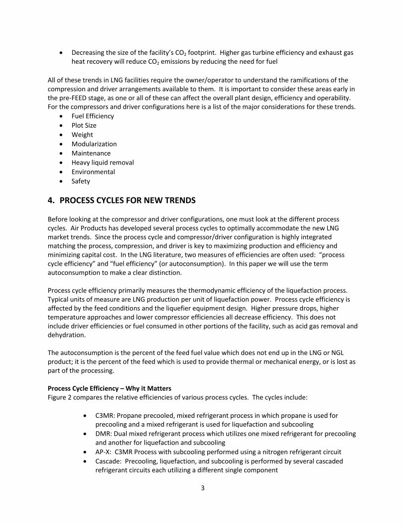
Before looking at the compressor and driver configurations, one must look at the different process cycles. Air Products has developed several process cycles to optimally accommodate the new LNG market trends. Since the process cycle and compressor/driver configuration is highly integrated matching the process, compression, and driver is key to maximizing production and efficiency and minimizing capital cost. In the LNG literature, two measures of efficiencies are often used: “process cycle efficiency” and “fuel efficiency” (or autoconsumption). In this paper we will use the term autoconsumption to make a clear distinction. Process cycle efficiency primarily measures the thermodynamic efficiency of the liquefaction process. Typical units of measure are LNG production per unit of liquefaction power. Process cycle efficiency is affected by the feed conditions and the liquefier equipment design. Higher pressure drops, higher temperature approaches and lower compressor efficiencies all decrease efficiency. This does not include driver efficiencies or fuel consumed in other portions of the facility, such as acid gas removal and dehydration. The autoconsumption is the percent of the feed fuel value which does not end up in the LNG or NGL product; it is the percent of the feed which is used to provide thermal or mechanical energy, or is lost as part of the processing. Process Cycle Efficiency – Why it Matters Figure 2 compares the relative efficiencies of various process cycles. The cycles include:
C3MR: Propane precooled, mixed refrigerant process in which propane is used for precooling and a mixed refrigerant is used for liquefaction and subcooling
DMR: Dual mixed refrigerant process which utilizes one mixed refrigerant for precooling and another for liquefaction and subcooling
AP-X: C3MR Process with subcooling performed using a nitrogen refrigerant circuit
Cascade: Precooling, liquefaction, and subcooling is performed by several cascaded refrigerant circuits each utilizing a different single component
4
SMR: Single mixed refrigerant process in which one mixed refrigerant is used for precooling, liquefaction, and subcooling
N2: Nitrogen expander refrigeration in which nitrogen is used as the refrigerant for precooling, liquefaction and subcooling
The process cycle efficiency measures the energy input to the liquefaction process. Any of these cycles can be adapted to a variety of driver types including industrial gas turbines, aeroderivative gas turbines, steam turbines or electric motors. Figure 2 also shows efficiency improvements Air Products has made to the basic N2 Recycle and Single Mixed refrigerant (SMR) cycles.
Figure 2 Relative Efficiencies of Process Cycles
Green: Modern Process Efficiencies
The choice of driver type will greatly impact autoconsumption. A cycle with low process efficiency can be helped by using more efficient drivers, which will reduce (i.e., improve) the autoconsumption. The recent large baseload plants in the LNG industry show that process efficiency is important:
Efficient precooled MR systems such as C3MR and AP-X cycles have been used for most large plants, because they increase the capacity of a single train, thus giving the owner significant economies of scale
Hydraulic turbines have been installed in most recent C3MR and AP-X trains. These turbines improve efficiency by 2 to 3%. For the plants where the compression trains are the limit, turbines increase production by 2 to 3%
The direction on some plants, especially on FLNG, is to look at the differences in the precooling options, whether it is a traditional propane system, or a mixed refrigerant system. Air Products has also investigated the use of one of the non-flammable hydroflurocarbon (HFC) as a possible propane replacement for precooling as a precooling refrigerant. The trend in the industry is to use either a propane or mixed refrigerant for the precooling loop for larger capacity trains and no separate precooling loop for smaller capacity trains.
5. DRIVER TRENDS

5
As stated previously, the selection of compressors and drivers depends on the different evaluation criteria for the new applications. Drivers in particular must be selected early in the design process to meet the project requirements. The trend or direction today is to look at aeroderivative gas turbines, especially in the midsized plant ranges and FLNG. Motor and steam turbine drives are also considered for specific applications. Below is some of the reasoning behind this.
Fuel Efficiency (Autoconsumption) Cost and efficiency tradeoffs are continuously considered for all plants. On the driver side, use of an aeroderivative gas turbine will improve the autoconsumption by 15-25% over the traditional industrial gas turbine. This percentage is even higher over steam turbines. For an all-motor driver design that includes local generation, the autoconsumption increases (less efficient) compared to direct drive gas turbines since losses due to electrical generation and transmission must be included. Table 1 gives typical driver efficiencies. Industrial gas turbines have efficiencies of 33-35%, and aeroderivative turbines are typically in the low 40% range. Historically, the efficiency of a steam turbine system has been in the low to mid 20% (including steam generation losses). A modern condensing steam turbine design could approach 30% and is dependent on the steam system design, boiler feedwater preheat circuits and turbine size and speed. For electric motor drives are used, the efficiency drops by 5 to 8%, due to generator and transmission losses. Table 1 shows that the use of aeroderivative gas turbines leads to lower autoconsumption regardless of the liquefaction process.
Table 1: Fuel Efficiency Ranges for Different Compression Drivers System Efficiency (%) Aeroderivative Gas Turbine 41-42 Industrial Gas Turbine 33-35 Motor Drive with Generation from an aeroderivative gas turbine 35-36 Motor Drive with Generation from an industrial gas turbine 27-29 Steam Turbine 22-30 Notes: 1) Efficiency is the fraction of shaft power delivered versus the fuel consumed. 2) All gas turbine efficiencies can improve with cogeneration 3) Efficiency is based on ISO efficiencies for gas turbines
Environmental Consideration: Local Environmental Requirements Some locations where LNG facilities may be located have some strict environmental considerations. The local environment requires a minimal disturbance for construction as well as operation. At more than one location, this has led to maximizing module construction where modules can be constructed in outside shops, moved to the new location, and then further connected and constructed. For the compression and driver area, this is much easier to do with an aeroderivative gas turbine design.
Environment Consideration: Carbon Footprint The environmental drive to emit less CO2 will push plant designs to lower autoconsumption. Lower autoconsumption is helped by higher efficiency gas turbines, especially the aeroderivative gas turbines. Using a heat recovery system in the facility will also reduce the carbon footprint.
6. SPECIFIC FLNG CONSIDERATIONS This section will discuss some of the additional considerations for FLNG.

6
Plot Size and Weight Topside weight and plot area are a major concern for FLNG. The aeroderivative engines are a smaller package and lighter weight than the frame engines. Part of the reason for the aeroderivative engine package being smaller is that a large starter motor is not required due to their inherent torque capabilities. There is more to this than a simple driver-to-driver comparison. The industrial gas turbines can be higher in power, thus a single industrial turbine could be used instead of a two or more aeroderivative engines. If an industrial turbine is used, additional consideration and size review is needed for the power generation for the starter/helper motor. For any FLNG application, the detail design of the foundation for the gas turbine/compressor package is required for ship movement issues and for suitability for maritime operation. Modularization
The aeroderivative gas turbine packages are all modularized due to their unique mounting methods. An example of a Rolls Royce package is shown below. These types of units are designed with discrete sections (e.g. inlet, engine enclosure, exhaust) that have been preassembled in the shop, allowing for either simplified assembly at the site, or further assembled on a larger module.
Figure 3: Modularization of Gas Turbine
This modular design concept is also used on land based applications although the extent of modularization may be less. Motor and Steam Turbine Drive For an FLNG location, using a motor drive with the electricity generated by gas turbines has the advantage that the power generation can be separated from the process equipment. The disadvantage is that two units are needed: electrical generation and electric motor. As mentioned before, with an all motor design, the overall fuel efficiency will be lower by 5-8% due to losses in the generation, transmission, and motor starting systems. A steam turbine driven compression train is also a possibility as this has been done in many land based plants successfully. With a steam turbine driven system, the water treatment and steam piping will need to be added to the ship. For both motors and steam turbines, there may be weight issues due to the added equipment necessary. Maintenance
Combustion air inlet filter (ISI
ducting included)
Mechanical Handling Skid
Gas Turbine Control Panel
Exhaust Stack and Silencer
(by others)
ISI Skid
GT Enclosure Ventilation
Intake
7
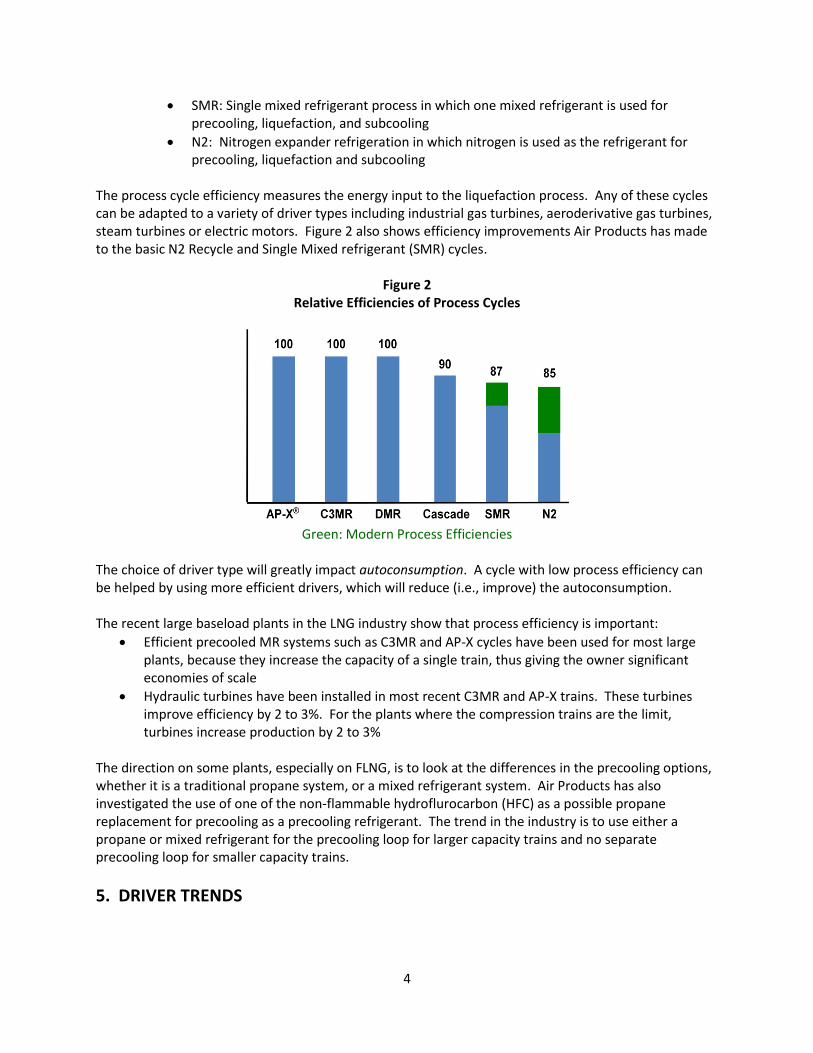
The maintenance on the drivers is important for the FLNG plants. The aeroderivative gas turbine design is such that the hot sections and compressor portions of the turbine can be removed easily, and replaced with spare sections. The worn or damaged section that is removed is taken to a maintenance facility for overhaul. The industrial gas turbines and steam turbines are maintained in the more traditional manner of rotating equipment, which is at the site by opening casing, checking bearings and seals, and rotor replacement. Figure 4 shows a hot section replacement method of an aeroderivative gas turbine from General Electric.
Figure 4: Side View of Hot section Replacement, Aeroderivative Gas Turbine
This short replacement time does come at an additional capital cost however. There is a need for a spare engine (or lease arrangement), and the repair work in the shop may be costly. It does not help to have a quick gas turbine repair interval if the compressor does not have a similar repair interval. With barrel type (axial split) compressors, the maintenance can be done similarly as the aero derivative gas turbine maintenance. This is where the compressor internal bundle is pulled, and replaced with a new bundle. The old bundle is then sent to a shop where it can be inspected and repaired. This is not possible with a horizontally split compressor, that has to be opened, and worked on in the field. Pictures of barrel compressor maintenance are shown below: Figure 5 and 6: Compressor Barrel Design, Replacement from Dresser- Rand

8
Fuel Composition, Heavies and Condensables Depending on the feed, there is a need to remove the heavier components. The storage volume for these constituents could be high, or else removal from the FLNG has to be done often. Burner systems for boilers and heat recovery steam generators (HRSG’s) can allow for a wider range of gases than some aeroderivative gas turbines. The desire to burn some of the heavy components on a ship requires an early discussion on type of driver. Safety Safety is the highest priority in any LNG facility. Relative to land-based plants, FLNG designs have the added constraint of limited plot area. One key safety item is the location of compressor and driver in relation to the LNG storage. The blading in the driver in particular is important for blade containment for the possibility of a blade failure within the casing. This may lead one to consider a motor driven or steam driven system where the gas turbine is installed at a different location on the ship.
7. Optimization: Process and Compression Now that we have seen some of the trends in the industry, Air Products did several studies on the compression fits for some of the new processes and with the aeroderivative gas turbines as the selected drivers.
Case 1: DMR Process- Optimum Speed A Dual Mixed Refrigerant (DMR) process with two compression services was modeled. Then a parametric study on different compressor configurations was completed using Air Products Process/Compressor optimizing programs. The purpose was to see if the savings in power with an aeroderivative gas turbine may be offset by a poor compressor selection. Since aeroderivative gas turbines are set with power and speed, our process/compressor design simulator was able to analyze the different options. In this study, we kept the production constant and varied the compressor’s speed and number of impellers. The conclusions from this study are below:
1. There is often a configuration that will fit these gas turbine drive power and speed 2. There can be a compressor efficiency penalty in doing so, especially if the number of
impellers used is selected poorly
9
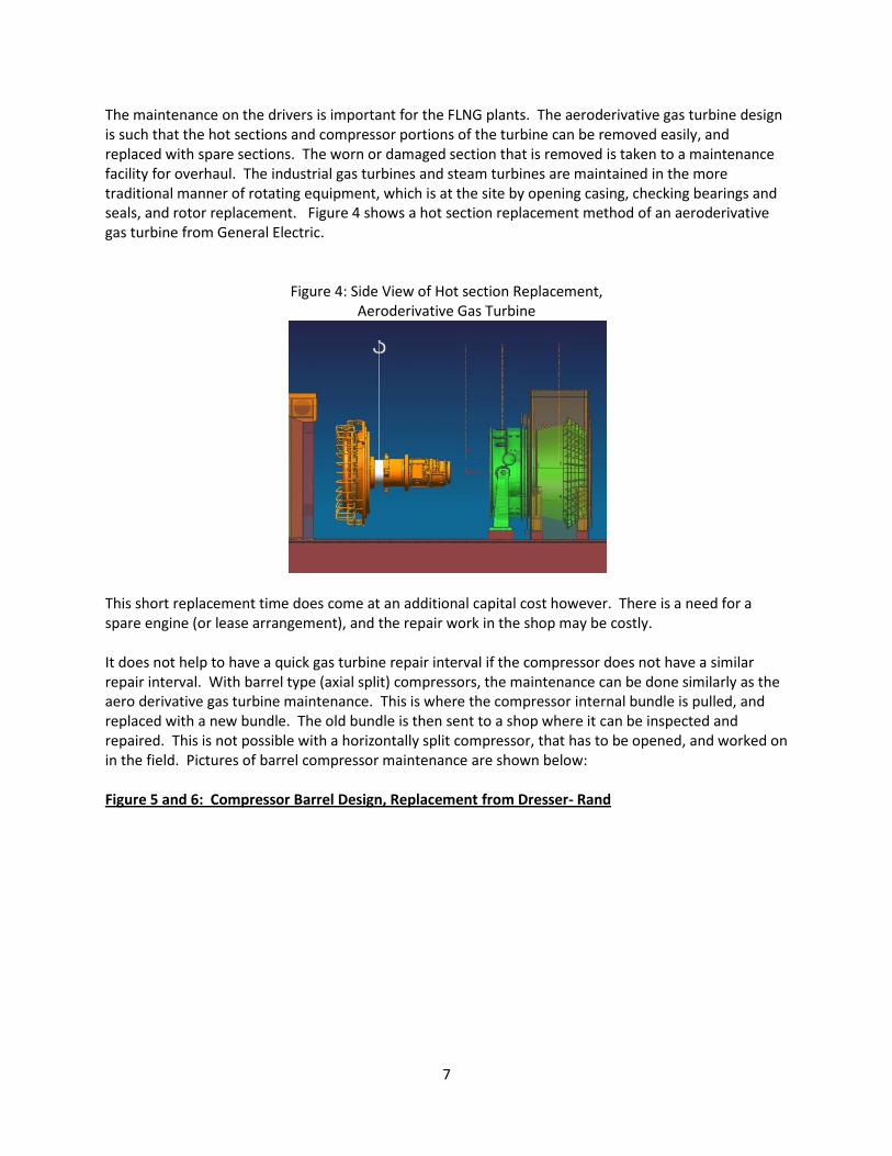
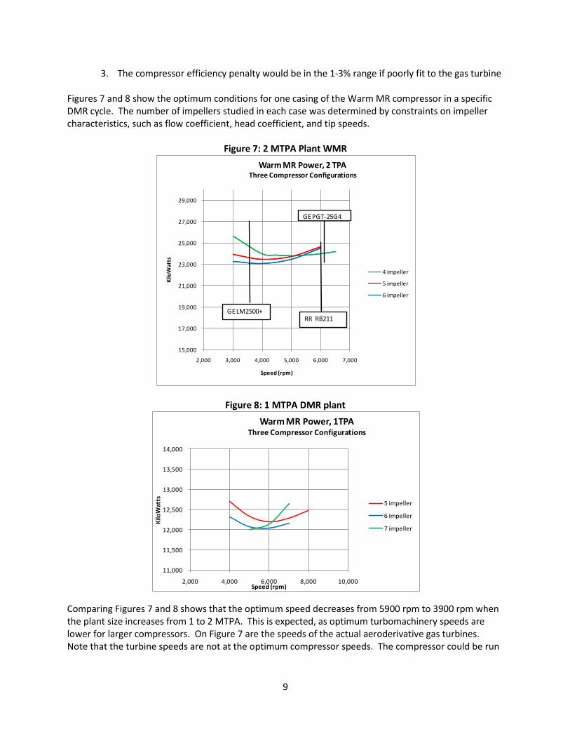
3. The compressor efficiency penalty would be in the 1-3% range if poorly fit to the gas turbine Figures 7 and 8 show the optimum conditions for one casing of the Warm MR compressor in a specific DMR cycle. The number of impellers studied in each case was determined by constraints on impeller characteristics, such as flow coefficient, head coefficient, and tip speeds.
Figure 7: 2 MTPA Plant WMR
Figure 8: 1 MTPA DMR plant
Comparing Figures 7 and 8 shows that the optimum speed decreases from 5900 rpm to 3900 rpm when the plant size increases from 1 to 2 MTPA. This is expected, as optimum turbomachinery speeds are lower for larger compressors. On Figure 7 are the speeds of the actual aeroderivative gas turbines. Note that the turbine speeds are not at the optimum compressor speeds. The compressor could be run
15,000
17,000
19,000
21,000
23,000
25,000
27,000
29,000
2,000 3,000 4,000 5,000 6,000 7,000
Kilo
Wat
ts
Speed (rpm)
Warm MR Power, 2 TPA Three Compressor Configurations
4 impeller
5 impeller
6 impeller
GELM2500+RR RB211
GE PGT-25G4
11,000
11,500
12,000
12,500
13,000
13,500
14,000
2,000 4,000 6,000 8,000 10,000
Kilo
Wat
ts
Speed (rpm)
Warm MR Power, 1TPA Three Compressor Configurations
5 impeller
6 impeller
7 impeller
10
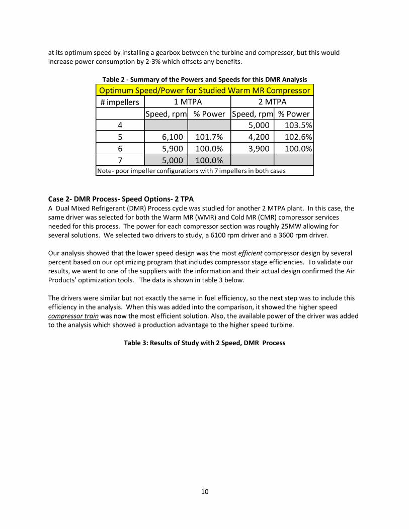
at its optimum speed by installing a gearbox between the turbine and compressor, but this would increase power consumption by 2-3% which offsets any benefits.
Table 2 - Summary of the Powers and Speeds for this DMR Analysis
Case 2- DMR Process- Speed Options- 2 TPA A Dual Mixed Refrigerant (DMR) Process cycle was studied for another 2 MTPA plant. In this case, the same driver was selected for both the Warm MR (WMR) and Cold MR (CMR) compressor services needed for this process. The power for each compressor section was roughly 25MW allowing for several solutions. We selected two drivers to study, a 6100 rpm driver and a 3600 rpm driver. Our analysis showed that the lower speed design was the most efficient compressor design by several percent based on our optimizing program that includes compressor stage efficiencies. To validate our results, we went to one of the suppliers with the information and their actual design confirmed the Air Products’ optimization tools. The data is shown in table 3 below. The drivers were similar but not exactly the same in fuel efficiency, so the next step was to include this efficiency in the analysis. When this was added into the comparison, it showed the higher speed compressor train was now the most efficient solution. Also, the available power of the driver was added to the analysis which showed a production advantage to the higher speed turbine.
Table 3: Results of Study with 2 Speed, DMR Process
# impellers
Speed, rpm % Power Speed, rpm % Power
4 5,000 103.5%
5 6,100 101.7% 4,200 102.6%
6 5,900 100.0% 3,900 100.0%
7 5,000 100.0%Note- poor impeller configurations with 7 impellers in both cases
1 MTPA 2 MTPA
Optimum Speed/Power for Studied Warm MR Compressor

11
In our review with the supplier, the compressor frames are larger for the lower speed turbine. The compressor selection based on efficiency alone will drive to the larger, slower speed compressor. This power difference was overwhelmed by the extra cost of the compressor and the gas turbine fit. Both of these studies also give rise to an observation. With an industrial turbine train, power is balanced between the propane and MR services. If an aeroderivative gas turbine solution is selected, the power may not be readily split the same way. This gives rise to additional gas turbines that can be used with some or all of the compression services in parallel. The study done above could also look at the WMR compressor being driven by one turbine, and the CMR compression being done by two in parallel. All of these studies illustrate the point of this paper. The various options should be carefully considered early in the pre-feed stage, and it is important to match the process with the machinery. Real differences, such as driver speed and parallel compression can have a significant impact on the project profitability.
Optimization: Parallel Compression The first C3MR plants had a single propane compressor and a single MR compressor, each with its own driver. However, the MR compressor has a higher power requirement, and with the SplitMR® process, the higher pressure stages of the MR compressor (HP MR) are placed on the same driver as the C3 compressor. This allows the two gas turbine drivers to have approximately the same load, and maximizes production when using two identical gas turbine drivers. Many of the new trends discussed earlier are favoring aeroderivative gas turbines. However, the maximum available power from a single aeroderivative turbine is not sufficient to power the needed compressor services. This which leads to the need to use parallel compression strings. With parallel compression, both the startup and tripping scenarios must be considered. When one compressor is suddenly taken off-line, the Main Cryogenic Heat Exchanger (MCHE) and the process will be affected, as well as the other operating compressor (or compressors). The control system must
Gas Turbines Turbine A Turbine B
Speed 3600 6100
WMR power 26.2 26.6
CMR power 50.7 51.5
Total Power 76.9 78.1
Compressor Power (relative) 100.0% 101.6%
GT efficiency difference 103.8% 1.0 (base)
Power w/GT efficiency difference 79.8 78.1
Compressor/GT Power (relative) 100.0% 97.8%
Available Power (relative) 98.8% 100%
Effect on Production -1.2% 0.0%
Power (MW)
RESULTS OF SPEED STUDY
12
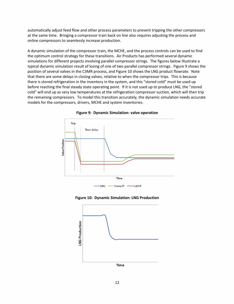
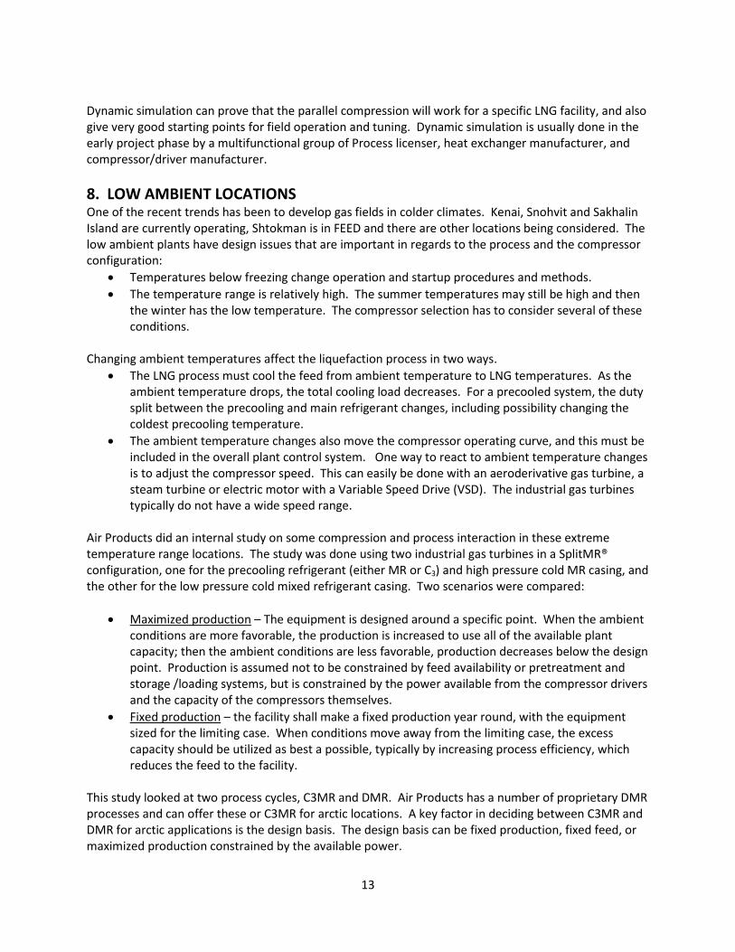
automatically adjust feed flow and other process parameters to prevent tripping the other compressors at the same time. Bringing a compressor train back on line also requires adjusting the process and online compressors to seamlessly increase production. A dynamic simulation of the compressor train, the MCHE, and the process controls can be used to find the optimum control strategy for these transitions. Air Products has performed several dynamic simulations for different projects involving parallel compressor strings. The figures below illustrate a typical dynamic simulation result of losing of one of two parallel compressor strings. Figure 9 shows the position of several valves in the C3MR process, and Figure 10 shows the LNG product flowrate. Note that there are some delays in closing valves, relative to when the compressor trips. This is because there is stored refrigeration in the inventory in the system, and this “stored cold” must be used up before reaching the final steady state operating point. If it is not used up to produce LNG, the “stored cold” will end up as very low temperatures at the refrigeration compressor suction, which will then trip the remaining compressors. To model this transition accurately, the dynamic simulation needs accurate models for the compressors, drivers, MCHE and system inventories.
Figure 9: Dynamic Simulation- valve operation
Figure 10: Dynamic Simulation: LNG Production
13
Dynamic simulation can prove that the parallel compression will work for a specific LNG facility, and also give very good starting points for field operation and tuning. Dynamic simulation is usually done in the early project phase by a multifunctional group of Process licenser, heat exchanger manufacturer, and compressor/driver manufacturer.
8. LOW AMBIENT LOCATIONS One of the recent trends has been to develop gas fields in colder climates. Kenai, Snohvit and Sakhalin Island are currently operating, Shtokman is in FEED and there are other locations being considered. The low ambient plants have design issues that are important in regards to the process and the compressor configuration:
Temperatures below freezing change operation and startup procedures and methods.
The temperature range is relatively high. The summer temperatures may still be high and then the winter has the low temperature. The compressor selection has to consider several of these conditions.
Changing ambient temperatures affect the liquefaction process in two ways.
The LNG process must cool the feed from ambient temperature to LNG temperatures. As the ambient temperature drops, the total cooling load decreases. For a precooled system, the duty split between the precooling and main refrigerant changes, including possibility changing the coldest precooling temperature.
The ambient temperature changes also move the compressor operating curve, and this must be included in the overall plant control system. One way to react to ambient temperature changes is to adjust the compressor speed. This can easily be done with an aeroderivative gas turbine, a steam turbine or electric motor with a Variable Speed Drive (VSD). The industrial gas turbines typically do not have a wide speed range.
Air Products did an internal study on some compression and process interaction in these extreme temperature range locations. The study was done using two industrial gas turbines in a SplitMR® configuration, one for the precooling refrigerant (either MR or C3) and high pressure cold MR casing, and the other for the low pressure cold mixed refrigerant casing. Two scenarios were compared:
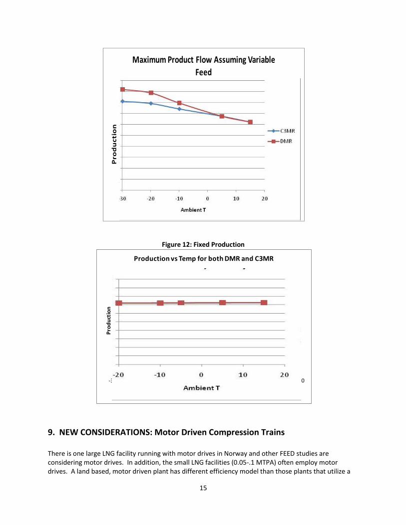
Maximized production – The equipment is designed around a specific point. When the ambient conditions are more favorable, the production is increased to use all of the available plant capacity; then the ambient conditions are less favorable, production decreases below the design point. Production is assumed not to be constrained by feed availability or pretreatment and storage /loading systems, but is constrained by the power available from the compressor drivers and the capacity of the compressors themselves.
Fixed production – the facility shall make a fixed production year round, with the equipment sized for the limiting case. When conditions move away from the limiting case, the excess capacity should be utilized as best a possible, typically by increasing process efficiency, which reduces the feed to the facility.
This study looked at two process cycles, C3MR and DMR. Air Products has a number of proprietary DMR processes and can offer these or C3MR for arctic locations. A key factor in deciding between C3MR and DMR for arctic applications is the design basis. The design basis can be fixed production, fixed feed, or maximized production constrained by the available power.
14
Maximized Production Results For this type of design basis, the objective is to maximize LNG production with the changing ambient temperature. For both designs, a SplitMR configuration was assumed. The compressor selection was set based on the design case and all other cases are rating cases using the compressor performance curves. Under these constraints, DMR shows a production advantage over C3MR for cold ambient conditions, assuming the same design production at warm conditions. Figure 11 compares C3MR with DMR for arctic conditions. For temperatures above the design case, C3MR and DMR produce the same amount of LNG. Below the design temperature, DMR shows an increasing production advantage over C3MR. This difference is primarily because as the ambient temperature gets colder, less precooling is needed. Production will generally increase simply due to the increased power available from the gas turbines and the colder heat sink for the compressor intercoolers. Additionally, the refrigerant compositions can be adjusted, which further increases production for lower ambient temperatures. With DMR, it is possible to shift some of the main refrigerant duty to the precoolant by adjusting the composition of both refrigerants, lowering the final precooling temperature. This better balances the refrigeration loads, and allows the total compressor power to be used to produce LNG. In C3MR, only the main refrigerant composition can be changed. The propane precooling composition obviously cannot be changed. The coldest precooling temperature is set to keep propane at a positive pressure. Therefore, it becomes necessary to recycle the propane compressor, which decreases efficiency. Part of this efficiency loss can be overcome by adjusting the main refrigerant composition to increase the duty of the lowest pressure evaporator, which in turn, increases the flow through the entire propane compressor, reducing the need for recycle and making more effective use of the propane compression. Despite the need to recycle, C3MR can offer a substantial production increase as the ambient temperature falls. The ability to increase production is due not only to the increased power available from the gas turbines and the colder heat sink for the compressor intercoolers, but also to the ability to optimize the mixed refrigerant composition. For colder ambient temperatures, the composition of the MR can be modified by decreasing the propane content and increasing the ethane content. Fixed Production For projects that require constant production, it is necessary to design all the equipment to make the design production at the hottest ambient temperature. For lower temperatures, the advantage of DMR is a reduced feed requirement due to reduced consumption due to the ability of the precooling MR to be operated at cold ambients without recycling. As shown in figure 12, this difference is a negligible fraction of the feed flow.
Figure 11: Maximized Production
15
Figure 12: Fixed Production
9. NEW CONSIDERATIONS: Motor Driven Compression Trains There is one large LNG facility running with motor drives in Norway and other FEED studies are considering motor drives. In addition, the small LNG facilities (0.05-.1 MTPA) often employ motor drives. A land based, motor driven plant has different efficiency model than those plants that utilize a
0
0.2
0.4
0.6
0.8
1
1.2
Pro
du
cti
on
Temperature, deg C
Maximum Product Flow Assuming Variable
Feed
0
0.2
0.4
0.6
0.8
1
1.2
-30 -20 -10 0 10 20 30
Pro
du
ctio
n
Temperature, deg C
Production vs Temp for both DMR and C3MR
16
gas turbine drive. These land based plants will be able to purchase the power from a utility at a set rate. The motor driven plants have specific challenges that are different than the gas turbine driven plants.
Normal motor speeds are set at a multiple of the line frequency (1200, 1500, 1800 rpm typically) which do not match the optimum compressor speeds.
For these motors, a gearbox is often required, especially on the smaller sizes. Gearboxes tend to lose 2% in efficiency of the drive.
VFD’s (Variable Frequency Drives) are the norm for startup and control of the refrigeration compressors.
A variable speed coupling (mechanical speed control) has been used in the past. This device will also have an efficiency loss, more in the order of 2-5%, depending on the complexity of the drive.
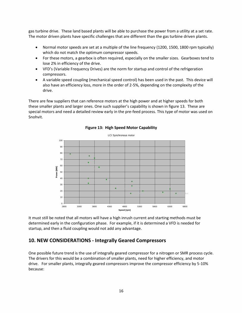
There are few suppliers that can reference motors at the high power and at higher speeds for both these smaller plants and larger ones. One such supplier’s capability is shown in figure 13. These are special motors and need a detailed review early in the pre-feed process. This type of motor was used on Snohvit.
Figure 13: High Speed Motor Capability
It must still be noted that all motors will have a high inrush current and starting methods must be determined early in the configuration phase. For example, if it is determined a VFD is needed for startup, and then a fluid coupling would not add any advantage.
10. NEW CONSIDERATIONS - Integrally Geared Compressors One possible future trend is the use of integrally geared compressor for a nitrogen or SMR process cycle. The drivers for this would be a combination of smaller plants, need for higher efficiency, and motor drive. For smaller plants, integrally geared compressors improve the compressor efficiency by 5-10% because:
LCI Synchronous motor
Persian [Quote]
Persian [Quote]
Pars [Quote]
Transcanada
Mossref
Hammerfest
NAM GLT
PetromontChurchover
Zeebrügge
St. Fergus
NAM Norg
Hammerfest
Karstoe
Hammerfest
0
10
20
30
40
50
60
70
80
90
100
2800 3300 3800 4300 4800 5300 5800 6300 6800
Speed [rpm]
Po
we
r [M
W]

17
The integrally geared machines have higher speeds available to use, and can utilize 2, 3, or 4 different shafts/speeds. This allows for the use of 3D impellers in all stages, with the improved impeller efficiency.
All impellers have a better axial inlet designs and less losses between impellers.
There are some tradeoffs with this style machine, including high speed gearing and additional seals due to number of shafts. These machines are fixed speed designs thus if a high degree of turndown is needed, then inlet guide vanes are utilized. Integrally geared compressors are well referenced in other industries (especially in Nitrogen) up to 30 mW, with some references up to 40 mW. Figure 13 is a picture of a typical integrally geared compressor from Siemens.
Figure 13: Integrally Geared Compressor
11. SUMMARY This paper showed many of the trends in natural gas liquefaction facilities. These trends show that there are more options available to the owner/operator. To develop a plant that meets their specific needs, the different processes, the drivers, and the compression needs to be integrated and understood early in the development.