Embed Size (px)
Citation preview
1 of 24
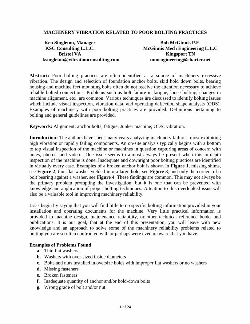
MACHINERY VIBRATION RELATED TO POOR BOLTING PRACTICES
Ken Singleton, Manager
KSC Consulting L.L.C.
Bristol VA
Bob McGinnis P.E.
McGinnis Mech Engineering L.L.C
Kingsport TN
Abstract: Poor bolting practices are often identified as a source of machinery excessive
vibration. The design and selection of foundation anchor bolts, skid hold down bolts, bearing
housing and machine feet mounting bolts often do not receive the attention necessary to achieve
reliable bolted connections. Problems such as bolt failure in fatigue, loose bolting, changes in
machine alignment, etc., are common. Various techniques are discussed to identify bolting issues
which include visual inspection, vibration data, and operating deflection shape analysis (ODS).
Examples of machinery with poor bolting practices are provided. Definitions pertaining to
bolting and general guidelines are provided.
Keywords: Alignment; anchor bolts; fatigue; Junker machine; ODS; vibration.
Introduction: The authors have spent many years analyzing machinery failures, most exhibiting
high vibration or rapidly failing components. An on-site analysis typically begins with a bottom
to top visual inspection of the machine or machines in question capturing areas of concern with
notes, photos, and video. One issue seems to almost always be present when this in-depth
inspection of the machine is done. Inadequate and downright poor bolting practices are identified
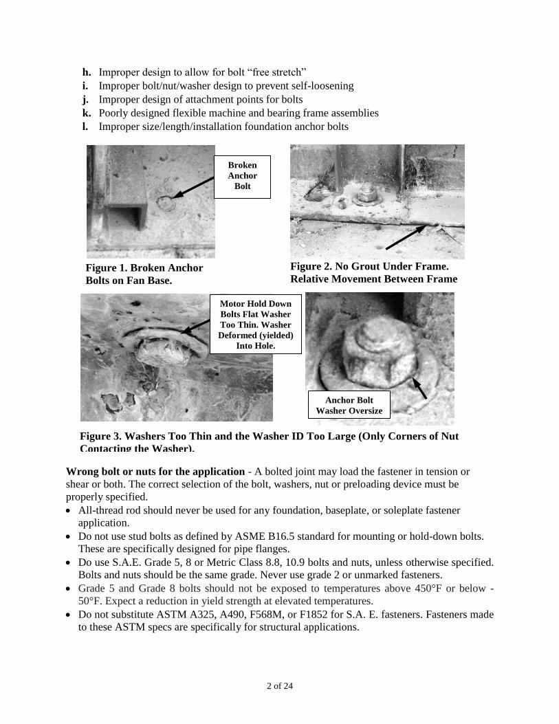
in virtually every case. Examples of a broken anchor bolt is shown in Figure 1, missing shims,
see Figure 2, thin flat washer yielded into a large hole, see Figure 3, and only the corners of a
bolt bearing against a washer, see Figure 4. These findings are common. This may not always be
the primary problem prompting the investigation, but it is one that can be prevented with
knowledge and application of proper bolting techniques. Attention to this overlooked issue will
also be a valuable tool in improving machinery reliability.
Let’s begin by saying that you will find little to no specific bolting information provided in your
installation and operating documents for the machine. Very little practical information is
provided in machine design, maintenance reliability, or other technical reference books and
publications. It is our goal, that at the end of this presentation, you will leave with new
knowledge and an approach to solve some of the machinery reliability problems related to
bolting you are so often confronted with or perhaps were even unaware that you have.
Examples of Problems Found
a. Thin flat washers.
b. Washers with over-sized inside diameters
c. Bolts and nuts installed in oversize holes with improper flat washers or no washers
d. Missing fasteners
e. Broken fasteners
f. Inadequate quantity of anchor and/or hold-down bolts
g. Wrong grade of bolt and/or nut
2 of 24
h. Improper design to allow for bolt “free stretch”
i. Improper bolt/nut/washer design to prevent self-loosening
j. Improper design of attachment points for bolts
k. Poorly designed flexible machine and bearing frame assemblies
l. Improper size/length/installation foundation anchor bolts
Wrong bolt or nuts for the application - A bolted joint may load the fastener in tension or
shear or both. The correct selection of the bolt, washers, nut or preloading device must be
properly specified.
All-thread rod should never be used for any foundation, baseplate, or soleplate fastener
application.
Do not use stud bolts as defined by ASME B16.5 standard for mounting or hold-down bolts.
These are specifically designed for pipe flanges.
Do use S.A.E. Grade 5, 8 or Metric Class 8.8, 10.9 bolts and nuts, unless otherwise specified.
Bolts and nuts should be the same grade. Never use grade 2 or unmarked fasteners.
Grade 5 and Grade 8 bolts should not be exposed to temperatures above 450°F or below -
50°F. Expect a reduction in yield strength at elevated temperatures.
Do not substitute ASTM A325, A490, F568M, or F1852 for S.A. E. fasteners. Fasteners made
to these ASTM specs are specifically for structural applications.
Anchor Bolt
Washer Oversize
ID
Motor Hold Down
Bolts Flat Washer
Too Thin. Washer
Deformed (yielded)
Into Hole.
Figure 3. Washers Too Thin and the Washer ID Too Large (Only Corners of Nut
Contacting the Washer).
Broken
Anchor
Bolt
Figure 1. Broken Anchor
Bolts on Fan Base.
Figure 2. No Grout Under Frame.
Relative Movement Between Frame
and Foundation.
3 of 24
Figure 4.
Full Tread
Bolt for
Thin
Mounting
Structures
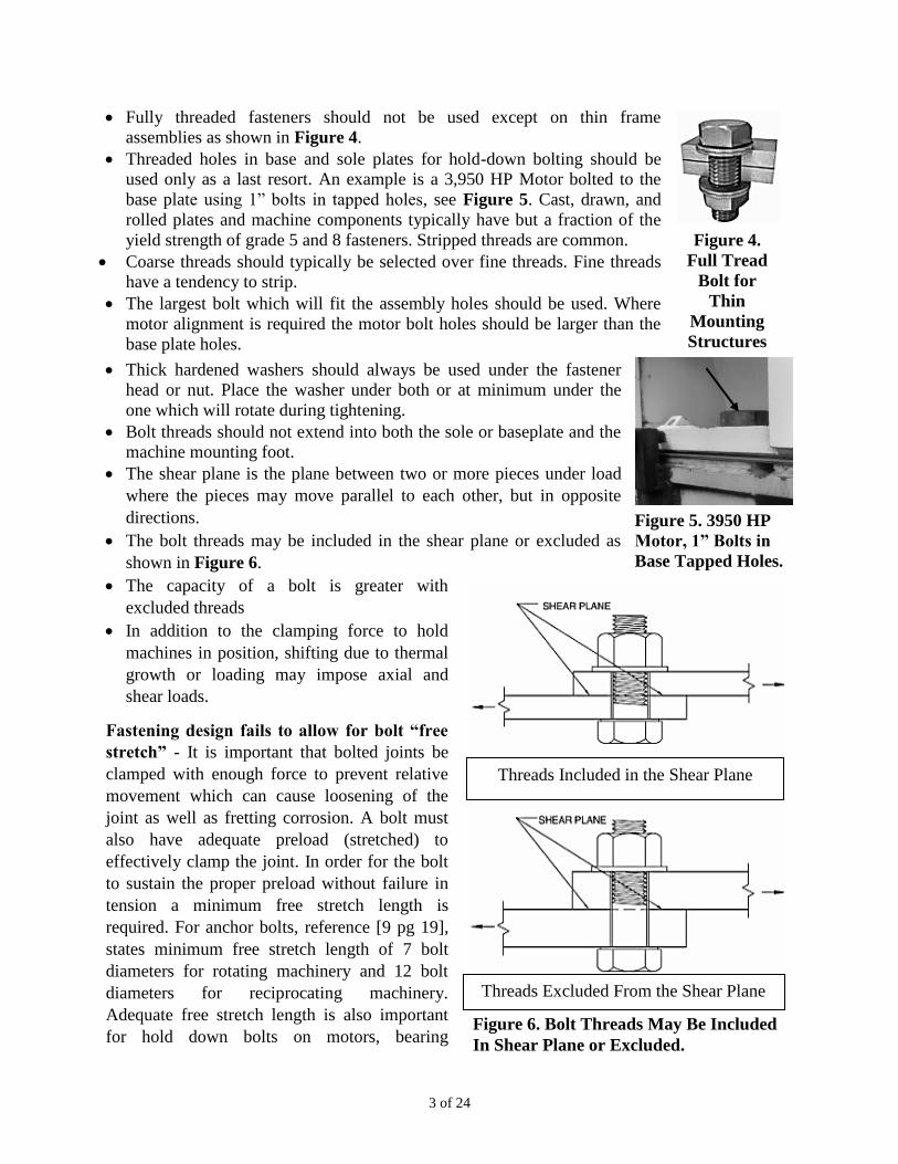
Fully threaded fasteners should not be used except on thin frame
assemblies as shown in Figure 4.
Threaded holes in base and sole plates for hold-down bolting should be
used only as a last resort. An example is a 3,950 HP Motor bolted to the
base plate using 1” bolts in tapped holes, see Figure 5. Cast, drawn, and
rolled plates and machine components typically have but a fraction of the
yield strength of grade 5 and 8 fasteners. Stripped threads are common.
Coarse threads should typically be selected over fine threads. Fine threads
have a tendency to strip.
The largest bolt which will fit the assembly holes should be used. Where
motor alignment is required the motor bolt holes should be larger than the
base plate holes.
Thick hardened washers should always be used under the fastener
head or nut. Place the washer under both or at minimum under the
one which will rotate during tightening.
Bolt threads should not extend into both the sole or baseplate and the
machine mounting foot.
The shear plane is the plane between two or more pieces under load
where the pieces may move parallel to each other, but in opposite
directions.
The bolt threads may be included in the shear plane or excluded as
shown in Figure 6.
The capacity of a bolt is greater with
excluded threads
In addition to the clamping force to hold
machines in position, shifting due to thermal
growth or loading may impose axial and
shear loads.
Fastening design fails to allow for bolt “free
stretch” - It is important that bolted joints be
clamped with enough force to prevent relative
movement which can cause loosening of the
joint as well as fretting corrosion. A bolt must
also have adequate preload (stretched) to
effectively clamp the joint. In order for the bolt
to sustain the proper preload without failure in
tension a minimum free stretch length is
required. For anchor bolts, reference [9 pg 19],
states minimum free stretch length of 7 bolt
diameters for rotating machinery and 12 bolt
diameters for reciprocating machinery.
Adequate free stretch length is also important
for hold down bolts on motors, bearing Figure 6. Bolt Threads May Be Included
In Shear Plane or Excluded.
Threads Excluded From the Shear Plane
Threads Included in the Shear Plane
Figure 5. 3950 HP
Motor, 1” Bolts in
Base Tapped Holes.
4 of 24
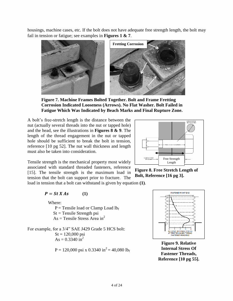
Figure 7. Machine Frames Bolted Together. Bolt and Frame Fretting
Corrosion Indicated Looseness (Arrows). No Flat Washer. Bolt Failed in
Fatigue Which Was Indicated by Beach Marks and Final Rupture Zone.
Fretting Corrosion
housings, machine cases, etc. If the bolt does not have adequate free strength length, the bolt may
fail in tension or fatigue; see examples in Figures 1 & 7.
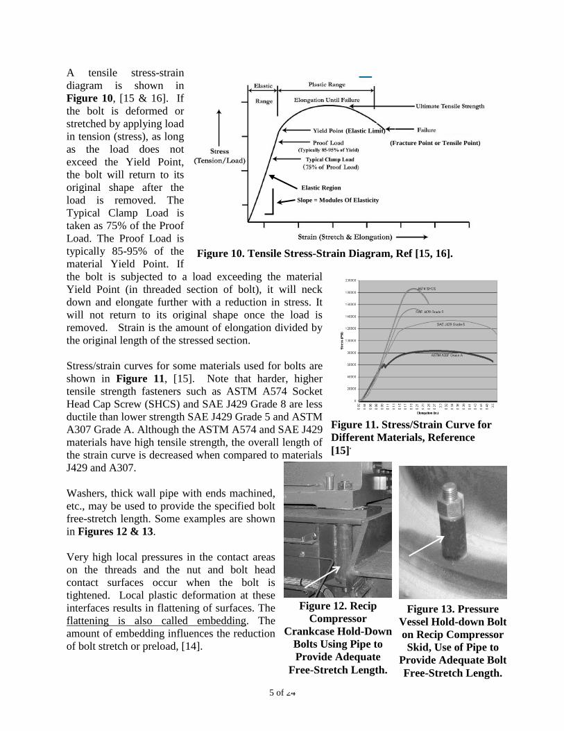
A bolt’s free-stretch length is the distance between the
nut (actually several threads into the nut or tapped hole)
and the head, see the illustrations in Figures 8 & 9. The
length of the thread engagement in the nut or tapped
hole should be sufficient to break the bolt in tension,
reference [10 pg 52]. The nut wall thickness and length
must also be taken into consideration.
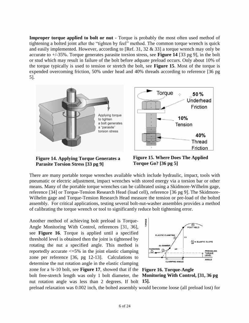
Tensile strength is the mechanical property most widely
associated with standard threaded fasteners, reference
[15]. The tensile strength is the maximum load in
tension that the bolt can support prior to fracture. The
load in tension that a bolt can withstand is given by equation (1).
𝑷 = 𝑺𝒕 𝑿 𝑨𝒔 (1)
Where:
P = Tensile load or Clamp Load lbf
St = Tensile Strength psi
As = Tensile Stress Area in2
For example, for a 3/4” SAE J429 Grade 5 HCS bolt:
St = 120,000 psi
As = 0.3340 in2
P = 120,000 psi x 0.3340 in2
= 40,080 lbf
Free Strength
Length
Figure 8. Free Stretch Length of
Bolt, Reference [16 pg 3].
Figure 9. Relative
Internal Stress Of
Fastener Threads,
Reference [10 pg 55].
5 of 24
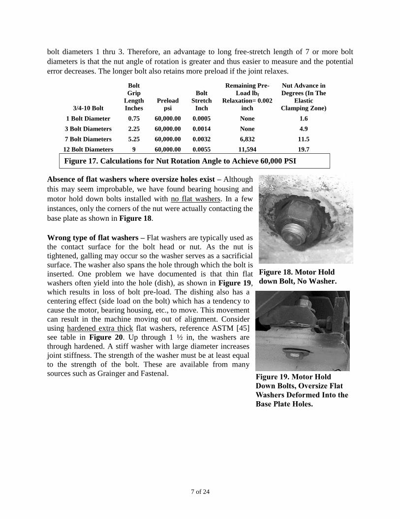
A tensile stress-strain
diagram is shown in
Figure 10, [15 & 16]. If
the bolt is deformed or
stretched by applying load
in tension (stress), as long
as the load does not
exceed the Yield Point,
the bolt will return to its
original shape after the
load is removed. The
Typical Clamp Load is
taken as 75% of the Proof
Load. The Proof Load is
typically 85-95% of the
material Yield Point. If
the bolt is subjected to a load exceeding the material
Yield Point (in threaded section of bolt), it will neck
down and elongate further with a reduction in stress. It
will not return to its original shape once the load is
removed. Strain is the amount of elongation divided by
the original length of the stressed section.
Stress/strain curves for some materials used for bolts are
shown in Figure 11, [15]. Note that harder, higher
tensile strength fasteners such as ASTM A574 Socket
Head Cap Screw (SHCS) and SAE J429 Grade 8 are less
ductile than lower strength SAE J429 Grade 5 and ASTM
A307 Grade A. Although the ASTM A574 and SAE J429
materials have high tensile strength, the overall length of
the strain curve is decreased when compared to materials
J429 and A307.
Washers, thick wall pipe with ends machined,
etc., may be used to provide the specified bolt
free-stretch length. Some examples are shown
in Figures 12 & 13.
Very high local pressures in the contact areas
on the threads and the nut and bolt head
contact surfaces occur when the bolt is
tightened. Local plastic deformation at these
interfaces results in flattening of surfaces. The
flattening is also called embedding. The
amount of embedding influences the reduction
of bolt stretch or preload, [14].
Figure 12. Recip
Compressor
Crankcase Hold-Down
Bolts Using Pipe to
Provide Adequate
Free-Stretch Length.
Figure 13. Pressure
Vessel Hold-down Bolt
on Recip Compressor
Skid, Use of Pipe to
Provide Adequate Bolt
Free-Stretch Length.
Figure 11. Stress/Strain Curve for
Different Materials, Reference
[15].
Figure 10. Tensile Stress-Strain Diagram, Ref [15, 16].
Slope = Modules Of Elasticity
Elastic Region
(Elastic Limit)
(Fracture Point or Tensile Point)
6 of 24
Improper torque applied to bolt or nut - Torque is probably the most often used method of
tightening a bolted joint after the “tighten by feel” method. The common torque wrench is quick
and easily implemented. However, according to [Ref. 31, 32 & 33] a torque wrench may only be
accurate to +/-35%. Torque generates parasite torsion stress, see Figure 14 [33 pg 9], in the bolt
or stud which may result in failure of the bolt before adquate preload occurs. Only about 10% of
the torque typically is used to tension or stretch the bolt, see Figure 15. Most of the torque is
expended overcoming friction, 50% under head and 40% threads according to reference [36 pg
5].
There are many portable torque wrenches available which include hydraulic, impact, tools with
pneumatic or electric adjustment, impact wrenches with stored energy via a torsion bar or other
means. Many of the portable torque wrenches can be calibrated using a Skidmore-Wilhelm gage,
reference [34] or Torque-Tension Research Head (load cell), reference [36 pg 9]. The Skidmore-
Wilhelm gage and Torque-Tension Research Head measure the tension or pre-load of the bolted
assembly. For critical applications, testing several bolt-nut-washer assembles provides a method
of calibrating the torque wrench or tool to significantly reduce bolt tightening error.
Another method of achieving bolt preload is Torque-
Angle Monitoring With Control, references [31, 36],
see Figure 16. Torque is applied until a specified
threshold level is obtained then the joint is tightened by
rotating the nut a specified angle. This method is
reportedly accurate <=5% in the joint elastic clamping
zone per reference [36, pg 12-13]. Calculations to
determine the nut rotation angle in the elastic clamping
zone for a ¾-10 bolt, see Figure 17, showed that if the
bolt free-stretch length was only 1 bolt diameter, the
nut rotation angle was less than 2 degrees. If bolt
preload relaxation was 0.002 inch, the bolted assembly would become loose (all preload lost) for
Figure 15. Where Does The Applied
Torque Go? [36 pg 5]
Figure 16. Torque-Angle
Monitoring With Control, [31, 36 pg
15].
Figure 14. Applying Torque Generates a
Parasite Torsion Stress [33 pg 9]
7 of 24
bolt diameters 1 thru 3. Therefore, an advantage to long free-stretch length of 7 or more bolt
diameters is that the nut angle of rotation is greater and thus easier to measure and the potential
error decreases. The longer bolt also retains more preload if the joint relaxes.
3/4-10 Bolt
Bolt
Grip
Length
Inches
Preload
psi
Bolt
Stretch
Inch
Remaining Pre-
Load lbf
Relaxation= 0.002
inch
Nut Advance in
Degrees (In The
Elastic
Clamping Zone)
1 Bolt Diameter 0.75 60,000.00 0.0005 None 1.6
3 Bolt Diameters 2.25 60,000.00 0.0014 None 4.9
7 Bolt Diameters 5.25 60,000.00 0.0032 6,832 11.5
12 Bolt Diameters 9 60,000.00 0.0055 11,594 19.7
Absence of flat washers where oversize holes exist – Although
this may seem improbable, we have found bearing housing and
motor hold down bolts installed with no flat washers. In a few
instances, only the corners of the nut were actually contacting the
base plate as shown in Figure 18.
Wrong type of flat washers – Flat washers are typically used as
the contact surface for the bolt head or nut. As the nut is
tightened, galling may occur so the washer serves as a sacrificial
surface. The washer also spans the hole through which the bolt is
inserted. One problem we have documented is that thin flat
washers often yield into the hole (dish), as shown in Figure 19,
which results in loss of bolt pre-load. The dishing also has a
centering effect (side load on the bolt) which has a tendency to
cause the motor, bearing housing, etc., to move. This movement
can result in the machine moving out of alignment. Consider
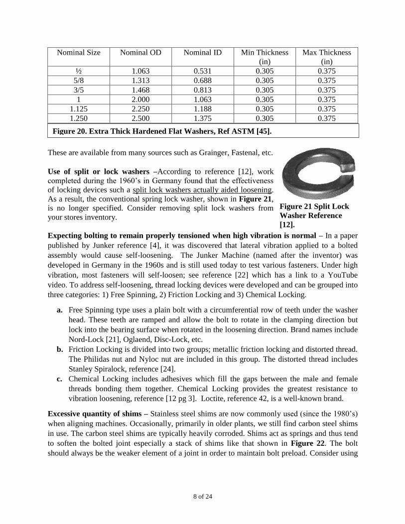
using hardened extra thick flat washers, reference ASTM [45]
see table in Figure 20. Up through 1 ½ in, the washers are
through hardened. A stiff washer with large diameter increases
joint stiffness. The strength of the washer must be at least equal
to the strength of the bolt. These are available from many
sources such as Grainger and Fastenal.
Figure 18. Motor Hold
down Bolt, No Washer.
Figure 19. Motor Hold
Down Bolts, Oversize Flat
Washers Deformed Into the
Base Plate Holes.
Figure 17. Calculations for Nut Rotation Angle to Achieve 60,000 PSI
Preload.
8 of 24
Nominal Size Nominal OD Nominal ID Min Thickness
(in)
Max Thickness
(in)
½ 1.063 0.531 0.305 0.375
5/8 1.313 0.688 0.305 0.375
3/5 1.468 0.813 0.305 0.375
1 2.000 1.063 0.305 0.375
1.125 2.250 1.188 0.305 0.375
1.250 2.500 1.375 0.305 0.375
These are available from many sources such as Grainger, Fastenal, etc.
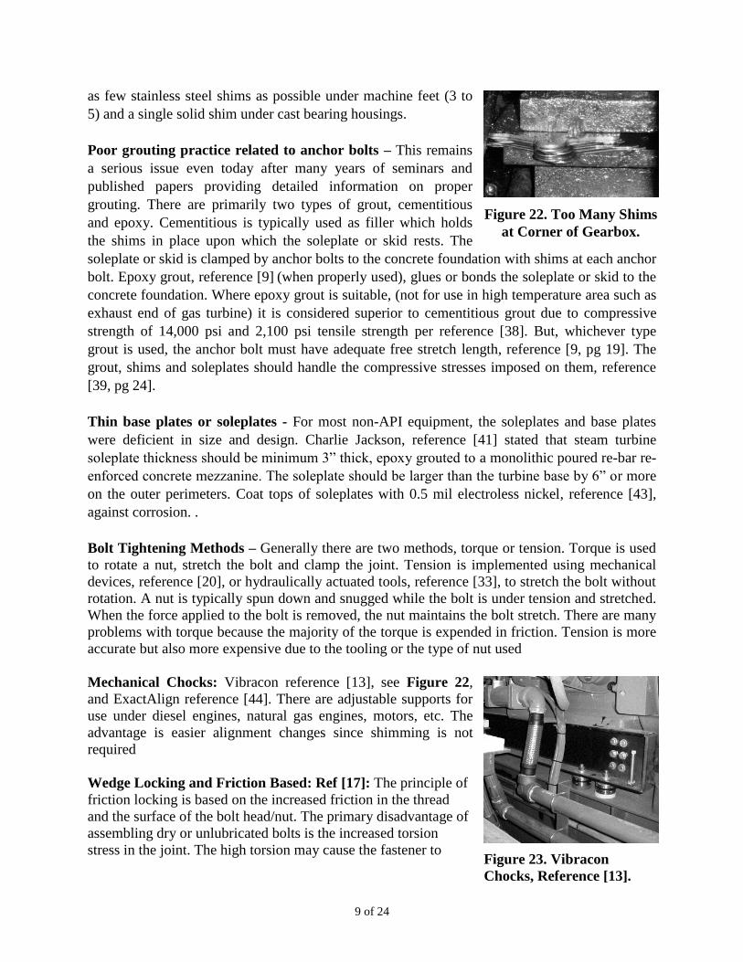
Use of split or lock washers –According to reference [12], work
completed during the 1960’s in Germany found that the effectiveness
of locking devices such a split lock washers actually aided loosening.
As a result, the conventional spring lock washer, shown in Figure 21,
is no longer specified. Consider removing split lock washers from
your stores inventory.
Expecting bolting to remain properly tensioned when high vibration is normal – In a paper
published by Junker reference [4], it was discovered that lateral vibration applied to a bolted
assembly would cause self-loosening. The Junker Machine (named after the inventor) was
developed in Germany in the 1960s and is still used today to test various fasteners. Under high
vibration, most fasteners will self-loosen; see reference [22] which has a link to a YouTube
video. To address self-loosening, thread locking devices were developed and can be grouped into
three categories: 1) Free Spinning, 2) Friction Locking and 3) Chemical Locking.
a. Free Spinning type uses a plain bolt with a circumferential row of teeth under the washer
head. These teeth are ramped and allow the bolt to rotate in the clamping direction but
lock into the bearing surface when rotated in the loosening direction. Brand names include
Nord-Lock [21], Oglaend, Disc-Lock, etc.
b. Friction Locking is divided into two groups; metallic friction locking and distorted thread.
The Philidas nut and Nyloc nut are included in this group. The distorted thread includes
Stanley Spiralock, reference [24].
c. Chemical Locking includes adhesives which fill the gaps between the male and female
threads bonding them together. Chemical Locking provides the greatest resistance to
vibration loosening, reference [12 pg 3]. Loctite, reference 42, is a well-known brand.
Excessive quantity of shims – Stainless steel shims are now commonly used (since the 1980’s)
when aligning machines. Occasionally, primarily in older plants, we still find carbon steel shims
in use. The carbon steel shims are typically heavily corroded. Shims act as springs and thus tend
to soften the bolted joint especially a stack of shims like that shown in Figure 22. The bolt
should always be the weaker element of a joint in order to maintain bolt preload. Consider using
Figure 21 Split Lock
Washer Reference
[12].
Figure 20. Extra Thick Hardened Flat Washers, Ref ASTM [45].
9 of 24
as few stainless steel shims as possible under machine feet (3 to
5) and a single solid shim under cast bearing housings.
Poor grouting practice related to anchor bolts – This remains
a serious issue even today after many years of seminars and
published papers providing detailed information on proper
grouting. There are primarily two types of grout, cementitious
and epoxy. Cementitious is typically used as filler which holds
the shims in place upon which the soleplate or skid rests. The
soleplate or skid is clamped by anchor bolts to the concrete foundation with shims at each anchor
bolt. Epoxy grout, reference [9] (when properly used), glues or bonds the soleplate or skid to the
concrete foundation. Where epoxy grout is suitable, (not for use in high temperature area such as
exhaust end of gas turbine) it is considered superior to cementitious grout due to compressive
strength of 14,000 psi and 2,100 psi tensile strength per reference [38]. But, whichever type
grout is used, the anchor bolt must have adequate free stretch length, reference [9, pg 19]. The
grout, shims and soleplates should handle the compressive stresses imposed on them, reference
[39, pg 24].
Thin base plates or soleplates - For most non-API equipment, the soleplates and base plates
were deficient in size and design. Charlie Jackson, reference [41] stated that steam turbine
soleplate thickness should be minimum 3” thick, epoxy grouted to a monolithic poured re-bar re-
enforced concrete mezzanine. The soleplate should be larger than the turbine base by 6” or more
on the outer perimeters. Coat tops of soleplates with 0.5 mil electroless nickel, reference [43],
against corrosion. .
Bolt Tightening Methods – Generally there are two methods, torque or tension. Torque is used
to rotate a nut, stretch the bolt and clamp the joint. Tension is implemented using mechanical
devices, reference [20], or hydraulically actuated tools, reference [33], to stretch the bolt without
rotation. A nut is typically spun down and snugged while the bolt is under tension and stretched.
When the force applied to the bolt is removed, the nut maintains the bolt stretch. There are many
problems with torque because the majority of the torque is expended in friction. Tension is more
accurate but also more expensive due to the tooling or the type of nut used
Mechanical Chocks: Vibracon reference [13], see Figure 22,
and ExactAlign reference [44]. There are adjustable supports for
use under diesel engines, natural gas engines, motors, etc. The
advantage is easier alignment changes since shimming is not
required
Wedge Locking and Friction Based: Ref [17]: The principle of
friction locking is based on the increased friction in the thread
and the surface of the bolt head/nut. The primary disadvantage of
assembling dry or unlubricated bolts is the increased torsion
stress in the joint. The high torsion may cause the fastener to
Figure 22. Too Many Shims
at Corner of Gearbox.
Figure 23. Vibracon
Chocks, Reference [13].
10 of 24
yield at a lower preload than expected. Since friction conditions are
uneven, the bolt may not reach the necessary preload. Insufficient
preload is the most common cause of bolting failure due to fatigue.
Thread lubricants are often used to minimize the friction and to obtain
more uniform clamp load. However, lubrication will significantly
reduce the locking ability of any friction based method.
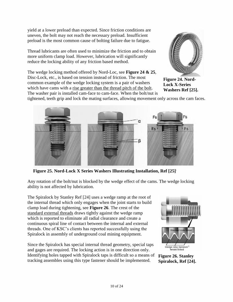
The wedge locking method offered by Nord-Loc, see Figure 24 & 25,
Disc-Lock, etc., is based on tension instead of friction. The most
common example of the wedge locking system is a pair of washers
which have cams with a rise greater than the thread pitch of the bolt.
The washer pair is installed cam-face to cam-face. When the bolt/nut is
tightened, teeth grip and lock the mating surfaces, allowing movement only across the cam faces.
Any rotation of the bolt/nut is blocked by the wedge effect of the cams. The wedge locking
ability is not affected by lubrication.
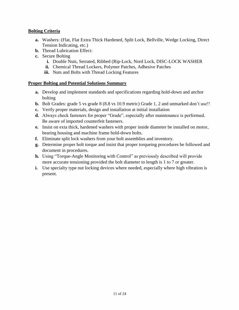
The Spiralock by Stanley Ref [24] uses a wedge ramp at the root of
the internal thread which only engages when the joint starts to build
clamp load during tightening, see Figure 26. The crest of the
standard external threads draws tightly against the wedge ramp
which is reported to eliminate all radial clearance and create a
continuous spiral line of contact between the internal and external
threads. One of KSC’s clients has reported successfully using the
Spiralock in assembly of underground coal mining equipment.
Since the Spiralock has special internal thread geometry, special taps
and gages are required. The locking action is in one direction only.
Identifying holes tapped with Spiralock taps is difficult so a means of
tracking assembles using this type fastener should be implemented.
Figure 24. Nord-
Lock X-Series
Washers Ref [25].
Figure 25. Nord-Lock X Series Washers Illustrating Installation, Ref [25].
Figure 26. Stanley
Spiralock, Ref [24].
11 of 24
Bolting Criteria
a. Washers: (Flat, Flat Extra Thick Hardened, Split Lock, Bellville, Wedge Locking, Direct
Tension Indicating, etc.)
b. Thread Lubrication Effect:
c. Secure Bolting
i. Double Nuts, Serrated, Ribbed (Rip-Lock, Nord Lock, DISC-LOCK WASHER
ii. Chemical Thread Lockers, Polymer Patches, Adhesive Patches
iii. Nuts and Bolts with Thread Locking Features
Proper Bolting and Potential Solutions Summary
a. Develop and implement standards and specifications regarding hold-down and anchor
bolting
b. Bolt Grades: grade 5 vs grade 8 (8.8 vs 10.9 metric) Grade 1, 2 and unmarked don’t use!!
c. Verify proper materials, design and installation at initial installation
d. Always check fasteners for proper “Grade”, especially after maintenance is performed.
Be aware of imported counterfeit fasteners.
e. Insist on exta thick, hardened washers with proper inside diameter be installed on motor,
bearing housing and machine frame hold-down bolts.
f. Eliminate split lock washers from your bolt assemblies and inventory.
g. Determine proper bolt torque and insist that proper torqueing procedures be followed and
document in procedures.
h. Using “Torque-Angle Monitoring with Control” as previously described will provide
more accurate tensioning provided the bolt diameter to length is 1 to 7 or greater.
i. Use specialty type nut locking devices where needed, especially where high vibration is
present.
12 of 24
Example 1: AMCA Arrangement 8 Fan. High Amplitude Vibration, Anchor Bolts
Breaking:
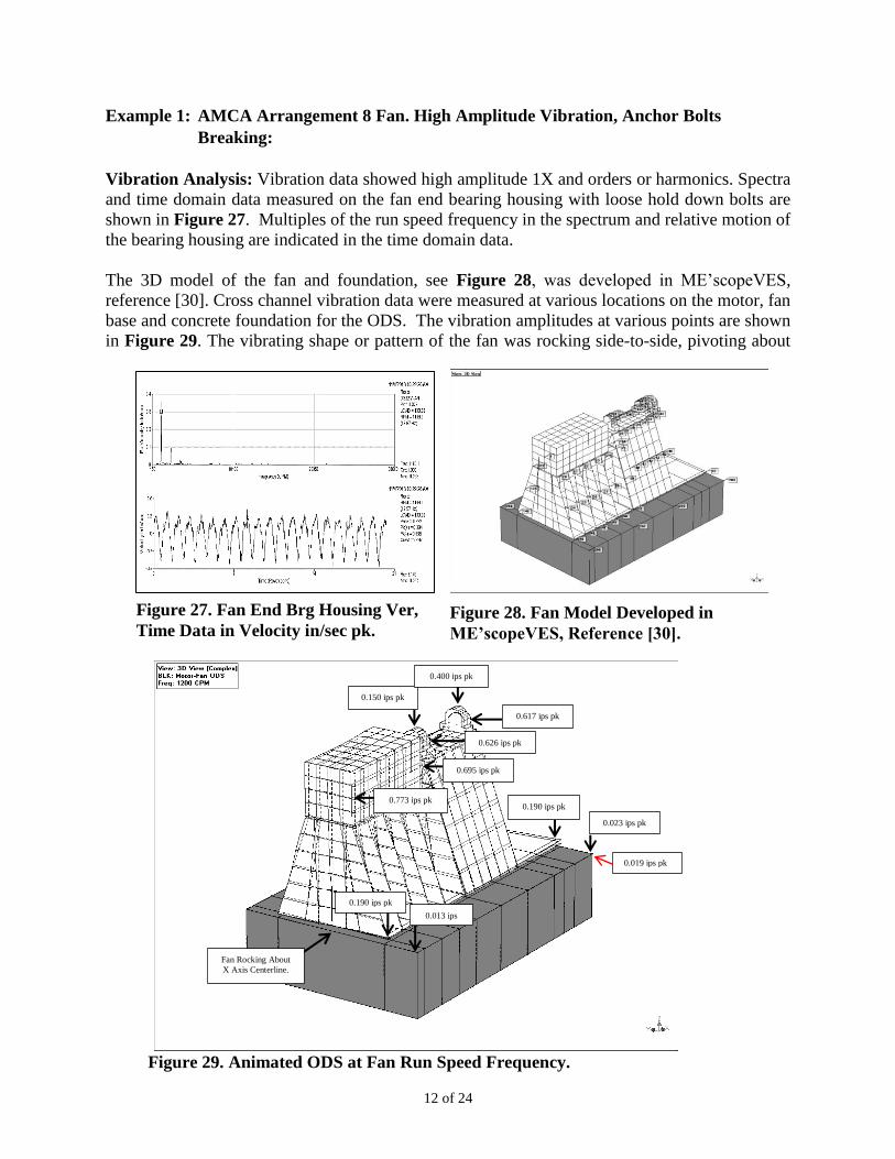
Vibration Analysis: Vibration data showed high amplitude 1X and orders or harmonics. Spectra
and time domain data measured on the fan end bearing housing with loose hold down bolts are
shown in Figure 27. Multiples of the run speed frequency in the spectrum and relative motion of
the bearing housing are indicated in the time domain data.
The 3D model of the fan and foundation, see Figure 28, was developed in ME’scopeVES,
reference [30]. Cross channel vibration data were measured at various locations on the motor, fan
base and concrete foundation for the ODS. The vibration amplitudes at various points are shown
in Figure 29. The vibrating shape or pattern of the fan was rocking side-to-side, pivoting about
Figure 27. Fan End Brg Housing Ver,
Time Data in Velocity in/sec pk. Figure 28. Fan Model Developed in
ME’scopeVES, Reference [30].
Figure 29. Animated ODS at Fan Run Speed Frequency.
0.013 ips
pk
0.190 ips pk
0.190 ips pk
0.023 ips pk
0.150 ips pk
0.400 ips pk
0.617 ips pk
0.626 ips pk
0.773 ips pk
0.695 ips pk
0.019 ips pk
Fan Rocking About
X Axis Centerline.
13 of 24
the X Axis just above the surface of the concrete base parallel to the shaft’s centerline. The
severe rocking motion of the entire fan assembly was a result of fan wheel unbalance (forcing
function) amplified by a rigid body mode natural frequency near running speed and fan rotor 1st
critical. The rigid body mode was caused by loose mounting of the fan base to the concrete
foundation (failed anchor bolts). The failed anchor bolts also lowered support stiffness which
lowered the rotor 1st critical down to run speed frequency.
Fan frame anchor bolts had only ½ inch free stretch length. Some of the anchor bolts were loose
and other bolts had experienced fatigue failure. The anchor bolt washers were too thin resulting
in deformation of the washers and inability of the bolted assembly to remain properly tensioned.
Typically a sleeve is installed around the bolts to prevent concrete and grout from contacting the
bolts. The sleeve allows the bolt to stretch over an adequate length of at least 7 diameters to
prevent over stressing during tightening. This long stretch length also allows the bolt to be more
elastic than the other components in the joint.
The motor hold down bolts had flat washers which were too thin and had deformed into the base
holes. This created a loose mounting and allowed relative motion or vibration of the motor to the
base. The fan bearing housing hold down bolts also used flat washers. Both bearing housings
exhibited looseness but the fan end bearing had significant relative motion to the bearing support
plate. There was very low amplitude vibration of the concrete pad indicating it had very little
participation in the fan vibration.
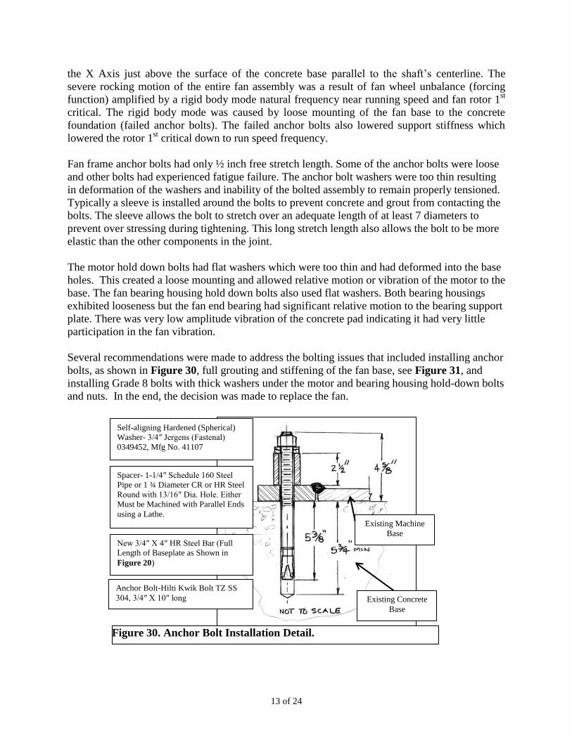
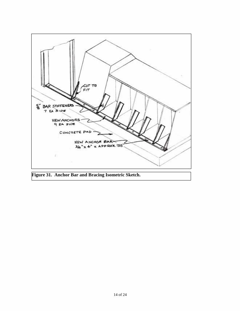
Several recommendations were made to address the bolting issues that included installing anchor
bolts, as shown in Figure 30, full grouting and stiffening of the fan base, see Figure 31, and
installing Grade 8 bolts with thick washers under the motor and bearing housing hold-down bolts
and nuts. In the end, the decision was made to replace the fan.
Self-aligning Hardened (Spherical)
Washer- 3/4″ Jergens (Fastenal)
0349452, Mfg No. 41107
Spacer- 1-1/4″ Schedule 160 Steel
Pipe or 1 ¾ Diameter CR or HR Steel
Round with 13/16″ Dia. Hole. Either
Must be Machined with Parallel Ends
using a Lathe.
New 3/4″ X 4″ HR Steel Bar (Full
Length of Baseplate as Shown in
Figure 20)
Anchor Bolt-Hilti Kwik Bolt TZ SS
304, 3/4″ X 10″ long Existing Concrete
Base
Existing Machine
Base
Figure 30. Anchor Bolt Installation Detail.
14 of 24
Figure 31. Anchor Bar and Bracing Isometric Sketch.
15 of 24
Example 2 AMCA Two Arrangement 8 Process Fans
The reported reliability problems for two process fans (A & B) were short bearing life, high
amplitude vibration and previous failure that resulted in a bent fan shaft. The fans were 500 HP,
56,433 ACFM, AMCA Arrangement 8. Our initial findings verified elevated vibration
amplitudes plus loose fan bearing housing and motor hold down bolts and bearing defect
frequencies. Vibration data measured during coastdown indicated fan rotor unbalance as the
primary forcing function. An ODS clearly showed motor relative motion of the bearing housings
and motors to the support plates and foundation rocking of Fan A.
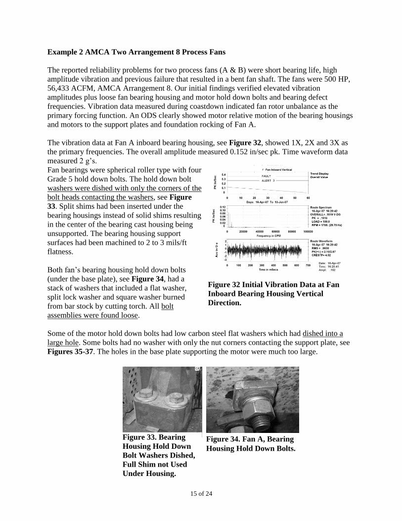
The vibration data at Fan A inboard bearing housing, see Figure 32, showed 1X, 2X and 3X as
the primary frequencies. The overall amplitude measured 0.152 in/sec pk. Time waveform data
measured 2 g’s.
Fan bearings were spherical roller type with four
Grade 5 hold down bolts. The hold down bolt
washers were dished with only the corners of the
bolt heads contacting the washers, see Figure
33. Split shims had been inserted under the
bearing housings instead of solid shims resulting
in the center of the bearing cast housing being
unsupported. The bearing housing support
surfaces had been machined to 2 to 3 mils/ft
flatness.
Both fan’s bearing housing hold down bolts
(under the base plate), see Figure 34, had a
stack of washers that included a flat washer,
split lock washer and square washer burned
from bar stock by cutting torch. All bolt
assemblies were found loose.
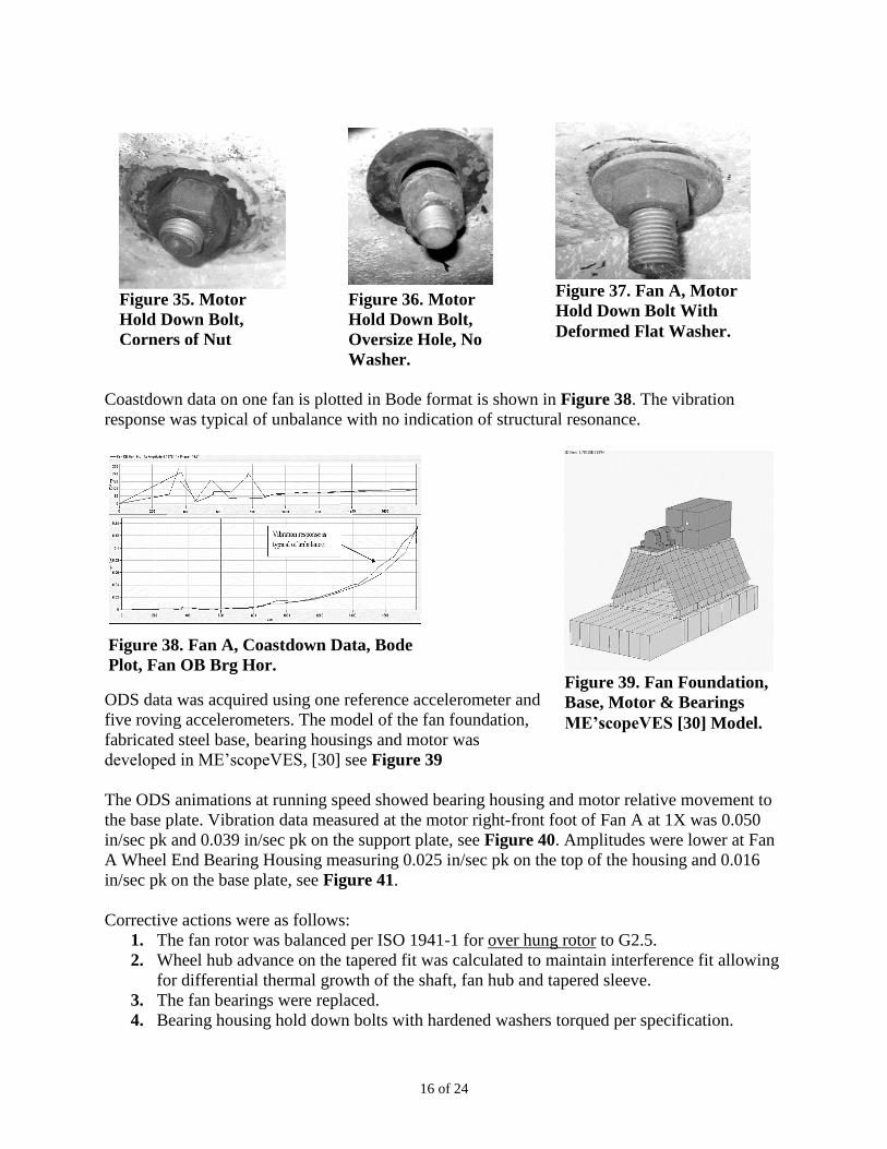
Some of the motor hold down bolts had low carbon steel flat washers which had dished into a
large hole. Some bolts had no washer with only the nut corners contacting the support plate, see
Figures 35-37. The holes in the base plate supporting the motor were much too large.
Figure 32 Initial Vibration Data at Fan
Inboard Bearing Housing Vertical
Direction.
Figure 34. Fan A, Bearing
Housing Hold Down Bolts.
Figure 33. Bearing
Housing Hold Down
Bolt Washers Dished,
Full Shim not Used
Under Housing.
16 of 24
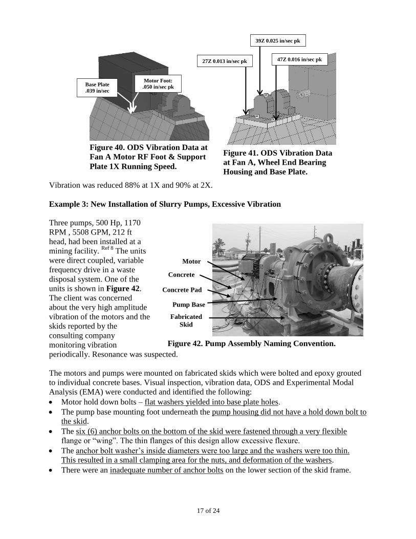
Coastdown data on one fan is plotted in Bode format is shown in Figure 38. The vibration
response was typical of unbalance with no indication of structural resonance.
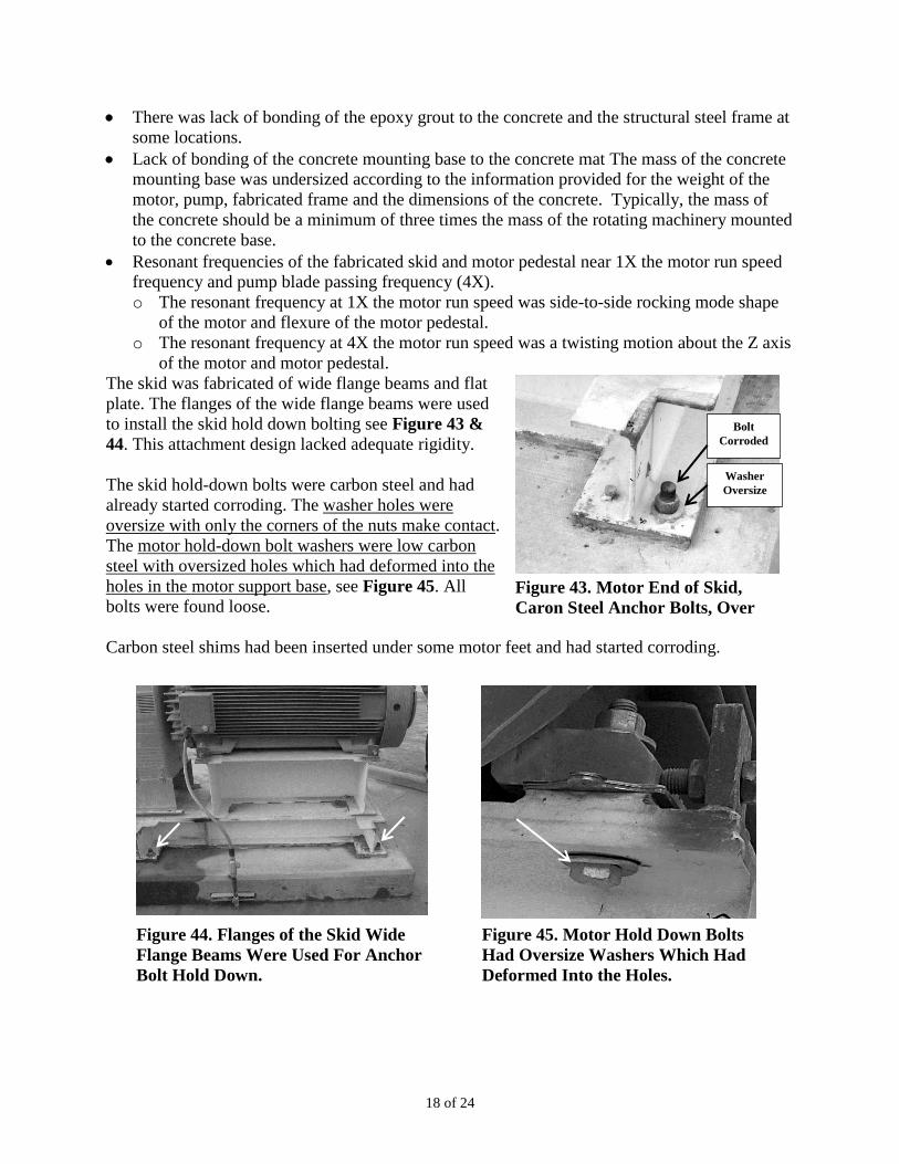
ODS data was acquired using one reference accelerometer and
five roving accelerometers. The model of the fan foundation,
fabricated steel base, bearing housings and motor was
developed in ME’scopeVES, [30] see Figure 39
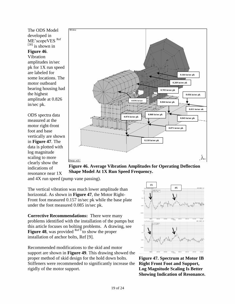
The ODS animations at running speed showed bearing housing and motor relative movement to
the base plate. Vibration data measured at the motor right-front foot of Fan A at 1X was 0.050
in/sec pk and 0.039 in/sec pk on the support plate, see Figure 40. Amplitudes were lower at Fan
A Wheel End Bearing Housing measuring 0.025 in/sec pk on the top of the housing and 0.016
in/sec pk on the base plate, see Figure 41.
Corrective actions were as follows:
1. The fan rotor was balanced per ISO 1941-1 for over hung rotor to G2.5.
2. Wheel hub advance on the tapered fit was calculated to maintain interference fit allowing
for differential thermal growth of the shaft, fan hub and tapered sleeve.
3. The fan bearings were replaced.
4. Bearing housing hold down bolts with hardened washers torqued per specification.
Figure 38. Fan A, Coastdown Data, Bode
Plot, Fan OB Brg Hor. Figure 39. Fan Foundation,
Base, Motor & Bearings
ME’scopeVES [30] Model.
Figure 37. Fan A, Motor
Hold Down Bolt With
Deformed Flat Washer.
Figure 35. Motor
Hold Down Bolt,
Corners of Nut
Contacting.
Figure 36. Motor
Hold Down Bolt,
Oversize Hole, No
Washer.
17 of 24
Vibration was reduced 88% at 1X and 90% at 2X.
Example 3: New Installation of Slurry Pumps, Excessive Vibration
Three pumps, 500 Hp, 1170
RPM , 5508 GPM, 212 ft
head, had been installed at a
mining facility. Ref 8
The units
were direct coupled, variable
frequency drive in a waste
disposal system. One of the
units is shown in Figure 42.
The client was concerned
about the very high amplitude
vibration of the motors and the
skids reported by the
consulting company
monitoring vibration
periodically. Resonance was suspected.
The motors and pumps were mounted on fabricated skids which were bolted and epoxy grouted
to individual concrete bases. Visual inspection, vibration data, ODS and Experimental Modal
Analysis (EMA) were conducted and identified the following:
Motor hold down bolts – flat washers yielded into base plate holes.
The pump base mounting foot underneath the pump housing did not have a hold down bolt to
the skid.
The six (6) anchor bolts on the bottom of the skid were fastened through a very flexible
flange or “wing”. The thin flanges of this design allow excessive flexure.
The anchor bolt washer’s inside diameters were too large and the washers were too thin.
This resulted in a small clamping area for the nuts, and deformation of the washers.
There were an inadequate number of anchor bolts on the lower section of the skid frame.
Figure 40. ODS Vibration Data at
Fan A Motor RF Foot & Support
Plate 1X Running Speed.
Motor Foot:
.050 in/sec pk Base Plate
.039 in/sec pk
Motor
Pedestal
Concrete
Base
Pump Base
Fabricated
Skid
Concrete Pad
Figure 42. Pump Assembly Naming Convention.
Figure 41. ODS Vibration Data
at Fan A, Wheel End Bearing
Housing and Base Plate.
47Z 0.016 in/sec pk
39Z 0.025 in/sec pk
27Z 0.013 in/sec pk
18 of 24
There was lack of bonding of the epoxy grout to the concrete and the structural steel frame at
some locations.
Lack of bonding of the concrete mounting base to the concrete mat The mass of the concrete
mounting base was undersized according to the information provided for the weight of the
motor, pump, fabricated frame and the dimensions of the concrete. Typically, the mass of
the concrete should be a minimum of three times the mass of the rotating machinery mounted
to the concrete base.
Resonant frequencies of the fabricated skid and motor pedestal near 1X the motor run speed
frequency and pump blade passing frequency (4X).
o The resonant frequency at 1X the motor run speed was side-to-side rocking mode shape
of the motor and flexure of the motor pedestal.
o The resonant frequency at 4X the motor run speed was a twisting motion about the Z axis
of the motor and motor pedestal.
The skid was fabricated of wide flange beams and flat
plate. The flanges of the wide flange beams were used
to install the skid hold down bolting see Figure 43 &
44. This attachment design lacked adequate rigidity.
The skid hold-down bolts were carbon steel and had
already started corroding. The washer holes were
oversize with only the corners of the nuts make contact.
The motor hold-down bolt washers were low carbon
steel with oversized holes which had deformed into the
holes in the motor support base, see Figure 45. All
bolts were found loose.
Carbon steel shims had been inserted under some motor feet and had started corroding.
Figure 43. Motor End of Skid,
Caron Steel Anchor Bolts, Over
Size Washers.
Bolt
Corroded
Washer
Oversize
Figure 45. Motor Hold Down Bolts
Had Oversize Washers Which Had
Deformed Into the Holes.
Figure 44. Flanges of the Skid Wide
Flange Beams Were Used For Anchor
Bolt Hold Down.
19 of 24
The ODS Model
developed in
ME’scopeVES Ref
[30] is shown in
Figure 46.
Vibration
amplitudes in/sec
pk for 1X run speed
are labeled for
some locations. The
motor outboard
bearing housing had
the highest
amplitude at 0.826
in/sec pk.
ODS spectra data
measured at the
motor right-front
foot and base
vertically are shown
in Figure 47. The
data is plotted with
log magnitude
scaling to more
clearly show the
indications of
resonance near 1X
and 4X run speed (pump vane passing).
The vertical vibration was much lower amplitude than
horizontal. As shown in Figure 47, the Motor Right-
Front foot measured 0.157 in/sec pk while the base plate
under the foot measured 0.085 in/sec pk.
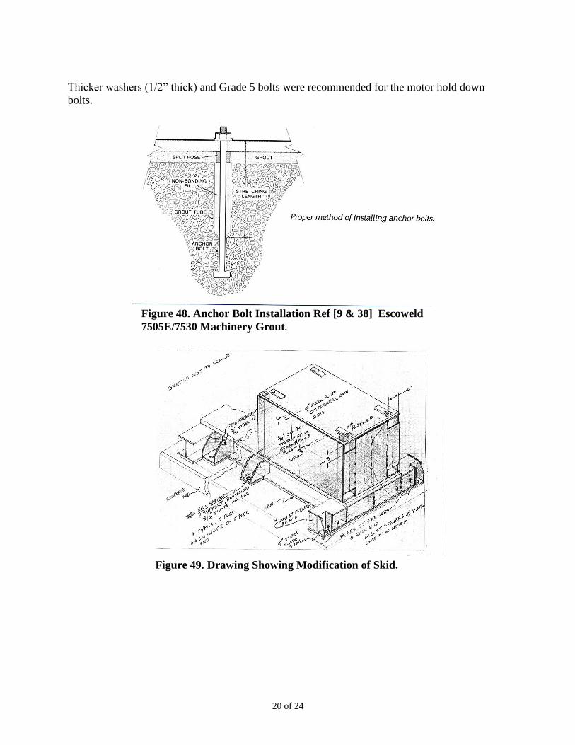
Corrective Recommendations: There were many
problems identified with the installation of the pumps but
this article focuses on bolting problems. A drawing, see
Figure 48, was provided Ref 9
to show the proper
installation of anchor bolts, Ref [9].
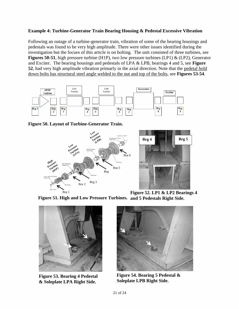
Recommended modifications to the skid and motor
support are shown in Figure 49. This drawing showed the
proper method of skid design for the hold down bolts.
Stiffeners were recommended to significantly increase the
rigidly of the motor support.
Figure 47. Spectrum at Motor IB
Right Front Foot and Support,
Log Magnitude Scaling Is Better
Showing Indication of Resonance.
1X
4X
Figure 46. Average Vibration Amplitudes for Operating Deflection
Shape Model At 1X Run Speed Frequency.
0.074 in/sec pk
0.110 in/sec pk
0.071 in/sec pk
0.043 in/sec pk
0.011 in/sec pk
0.036 in/sec pk
0.044 in/sec pk
0.060 in/sec pk
0.703 in/sec pk
0.269 in/sec pk
0.164 in/sec pk
0.826 in/sec
pk
20 of 24
Thicker washers (1/2” thick) and Grade 5 bolts were recommended for the motor hold down
bolts.
Figure 48. Anchor Bolt Installation Ref [9 & 38] Escoweld
7505E/7530 Machinery Grout.
Figure 49. Drawing Showing Modification of Skid.
21 of 24
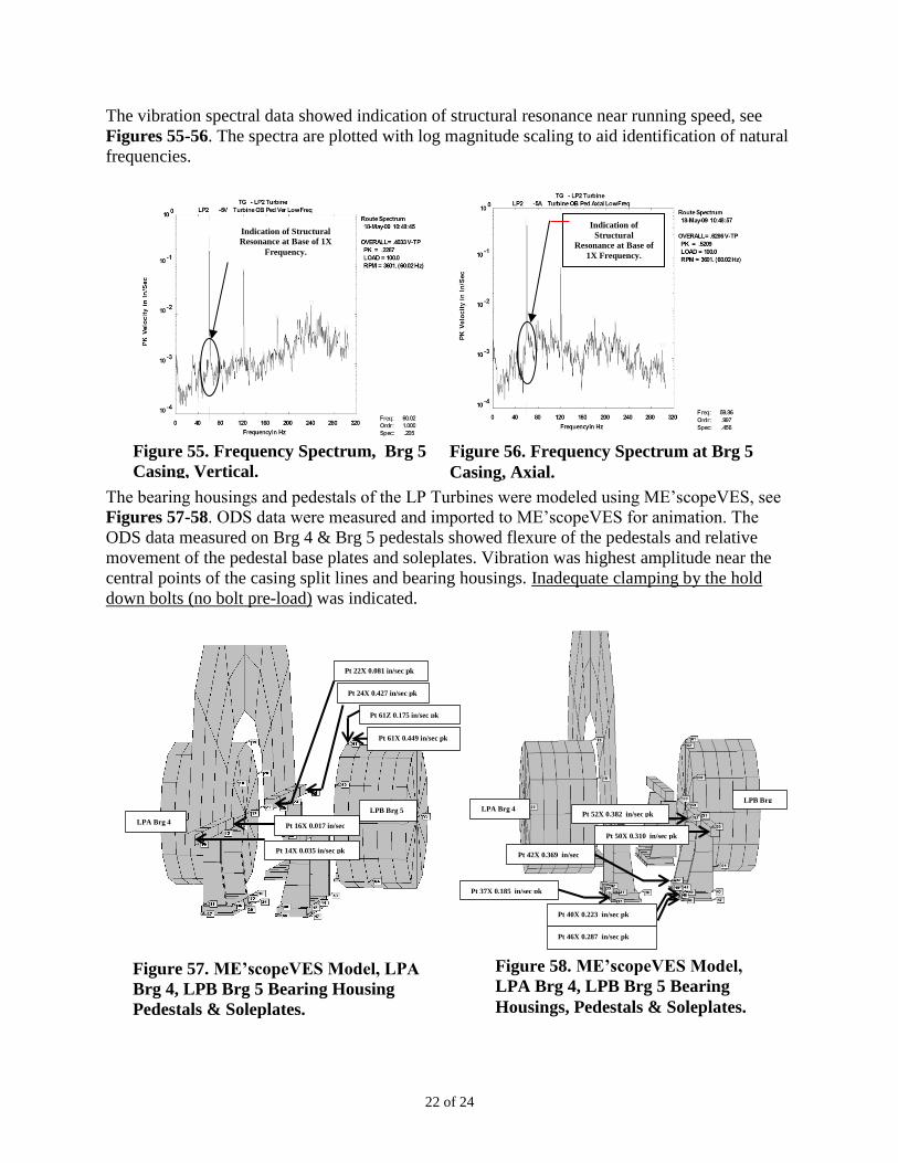
Example 4: Turbine-Generator Train Bearing Housing & Pedestal Excessive Vibration
Following an outage of a turbine-generator train, vibration of some of the bearing housings and
pedestals was found to be very high amplitude. There were other issues identified during the
investigation but the focues of this article is on bolting. The unit consisted of three turbines, see
Figures 50-51, high pressure turbine (H1P), two low pressure turbines (LP1) & (LP2), Generator
and Exciter. The bearing housings and pedestals of LPA & LPB, bearings 4 and 5, see Figure
52, had very high amplitude vibration primarly in the axial direction. Note that the pedetal hold
down bolts has structural steel angle welded to the nut and top of the bolts, see Figures 53-54.
Figure 51. High and Low Pressure Turbines.
Figure 53. Bearing 4 Pedestal
& Soleplate LPA Right Side.
Figure 54. Bearing 5 Pedestal &
Soleplate LPB Right Side.
Brg 1
Brg 2 Brg 3
Brg
4
Brg 5
Brg 6
Figure 52. LP1 & LP2 Bearings 4
and 5 Pedestals Right Side.
Brg 4 Brg 5
Figure 50. Layout of Turbine-Generator Train.
LPA
Turbine
LPB
Turbine
22 of 24
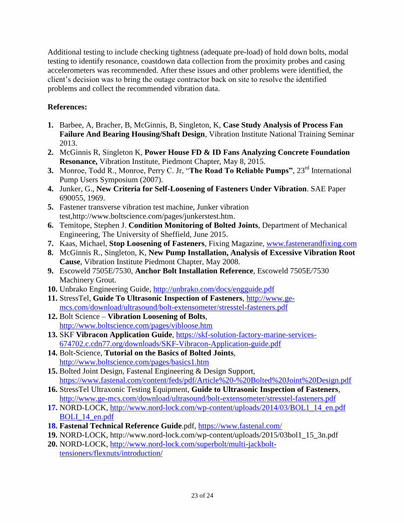
The vibration spectral data showed indication of structural resonance near running speed, see
Figures 55-56. The spectra are plotted with log magnitude scaling to aid identification of natural
frequencies.
The bearing housings and pedestals of the LP Turbines were modeled using ME’scopeVES, see
Figures 57-58. ODS data were measured and imported to ME’scopeVES for animation. The
ODS data measured on Brg 4 & Brg 5 pedestals showed flexure of the pedestals and relative
movement of the pedestal base plates and soleplates. Vibration was highest amplitude near the
central points of the casing split lines and bearing housings. Inadequate clamping by the hold
down bolts (no bolt pre-load) was indicated.
Figure 55. Frequency Spectrum, Brg 5
Casing, Vertical.
Indication of Structural
Resonance at Base of 1X
Frequency.
Figure 56. Frequency Spectrum at Brg 5
Casing, Axial.
Indication of
Structural
Resonance at Base of
1X Frequency.
Figure 58. ME’scopeVES Model,
LPA Brg 4, LPB Brg 5 Bearing
Housings, Pedestals & Soleplates.
Pt 42X 0.369 in/sec
pk
Pt 37X 0.185 in/sec pk
Pt 46X 0.287 in/sec pk
Pt 40X 0.223 in/sec pk
Pt 50X 0.310 in/sec pk
Pt 52X 0.382 in/sec pk LPA Brg 4
LPB Brg
5
Figure 57. ME’scopeVES Model, LPA
Brg 4, LPB Brg 5 Bearing Housing
Pedestals & Soleplates.
Pt 24X 0.427 in/sec pk
Pt 22X 0.081 in/sec pk
Pt 61Z 0.175 in/sec pk
Pt 61X 0.449 in/sec pk
LPA Brg 4
LPB Brg 5
Pt 16X 0.017 in/sec
pk
Pt 14X 0.035 in/sec pk
23 of 24
Additional testing to include checking tightness (adequate pre-load) of hold down bolts, modal
testing to identify resonance, coastdown data collection from the proximity probes and casing
accelerometers was recommended. After these issues and other problems were identified, the
client’s decision was to bring the outage contractor back on site to resolve the identified
problems and collect the recommended vibration data.
References:
1. Barbee, A, Bracher, B, McGinnis, B, Singleton, K, Case Study Analysis of Process Fan
Failure And Bearing Housing/Shaft Design, Vibration Institute National Training Seminar
2013.
2. McGinnis R, Singleton K, Power House FD & ID Fans Analyzing Concrete Foundation
Resonance, Vibration Institute, Piedmont Chapter, May 8, 2015.
3. Monroe, Todd R., Monroe, Perry C. Jr, “The Road To Reliable Pumps”, 23rd
International
Pump Users Symposium (2007).
4. Junker, G., New Criteria for Self-Loosening of Fasteners Under Vibration. SAE Paper
690055, 1969.
5. Fastener transverse vibration test machine, Junker vibration
test,http://www.boltscience.com/pages/junkerstest.htm.
6. Temitope, Stephen J. Condition Monitoring of Bolted Joints, Department of Mechanical
Engineering, The University of Sheffield, June 2015.
7. Kaas, Michael, Stop Loosening of Fasteners, Fixing Magazine, www.fastenerandfixing.com
8. McGinnis R., Singleton, K, New Pump Installation, Analysis of Excessive Vibration Root
Cause, Vibration Institute Piedmont Chapter, May 2008.
9. Escoweld 7505E/7530, Anchor Bolt Installation Reference, Escoweld 7505E/7530
Machinery Grout.
10. Unbrako Engineering Guide, http://unbrako.com/docs/engguide.pdf
11. StressTel, Guide To Ultrasonic Inspection of Fasteners, http://www.ge-
mcs.com/download/ultrasound/bolt-extensometer/stresstel-fasteners.pdf
12. Bolt Science – Vibration Loosening of Bolts,
http://www.boltscience.com/pages/vibloose.htm
13. SKF Vibracon Application Guide, https://skf-solution-factory-marine-services-
674702.c.cdn77.org/downloads/SKF-Vibracon-Application-guide.pdf
14. Bolt-Science, Tutorial on the Basics of Bolted Joints,
http://www.boltscience.com/pages/basics1.htm
15. Bolted Joint Design, Fastenal Engineering & Design Support,
https://www.fastenal.com/content/feds/pdf/Article%20-%20Bolted%20Joint%20Design.pdf
16. StressTel Ultraxonic Testing Equipment, Guide to Ultrasonic Inspection of Fasteners,
http://www.ge-mcs.com/download/ultrasound/bolt-extensometer/stresstel-fasteners.pdf
17. NORD-LOCK, http://www.nord-lock.com/wp-content/uploads/2014/03/BOL1_14_en.pdf
BOLI_14_en.pdf
18. Fastenal Technical Reference Guide.pdf, https://www.fastenal.com/
19. NORD-LOCK, http://www.nord-lock.com/wp-content/uploads/2015/03bol1_15_3n.pdf
20. NORD-LOCK, http://www.nord-lock.com/superbolt/multi-jackbolt-
tensioners/flexnuts/introduction/
24 of 24
21. NORD-LOCK, http://www.nord-lock.com/nord-lock/multifunctional-wedge-locking/x-
series-washers/joint-guide/
22. NORD-LOCK, Junker Machine Test Video,
https://www.youtube.com/watch?v=IKwWu2w1gGk
23. Applied Bolting Technology, Applied Bolting Brochure,
http://www.appliedbolting.com/our-brochure.html
24. Stanley, Spiralock Fasteners & Threading Tools Product Specifications,
http://www.stanleyengineeredfastening.com/sites/www.emhartamericas.com/files/downloads
/Spiralock%20Products%20Catalog.pdf
25. NORD-LOCK, X Series Washers 2012, http://www.nord-lock.com/2012/09/28/nord-lock-x-
series-bolt-security-without-compromise/
26. SmartBolts, Visual Indication System Product Catalog, www.smartbolts.com
27. Hilti North America Product Technical Guide, www.us.hilti.com/anchors
28. Jergens Workholding Components.pdf pg 260, pg 268,
http://www.jergensinc.com/Spherical-Flange-Assemblies
29. RBW Manufacturing, Helpful Hints, www.rbwmfg.com/wp-
content/uploads/2012/02/HelpfulHints2.pdf
30. Vibrant Technology, www. http://vibetech.com/
31. Oberg, E., Jones. F., Horton, H., and Ryffel, H: “Machinery’s Handbook”, 27th
Edition,
Industrial Press Inc., New York, 2004
32. “Criteria for Preloaded Bolts”, NSTS–08307, Rev. A, NASA, 1998
33. SKF, “Bolt-Tightening Handbook”,
https://www.google.com/?gws_rd=ssl#q=skf+bolt+tightening+handbook
34. Skidmorewilhelm, “User Manual Model MZ-100 Bolt Tension Calibrator”,
http://www.skidmore-wilhelm.com/
35. Raynor-Keck, Lisa, “Torque Vs. Tension: Is There a Clear Winner?”, Fastorq,
www.fastorq.com
36. Shobert, Ralph S. P.E., “Engineering Fundamentals of Threaded Fastener Design and
Analysis”, http://www.hexagon.de/rs/engineering%20fundamentals.pdf.
37. Grainger, https://www.grainger.com/product/TE-CO-Heavy-Duty-Washer-
2YJG5?s_pp=false&picUrl=//static.grainger.com/rp/s/is/image/Grainger/2YJF8_AS01?$smt
humb$
38. Escoweld 705E/7530, Technical Bulletin # 1612D,
http://na.itwengineeredpolymers.com/downloads/tds/Escoweld-7505E-tds.pdf
39. Lee, James Pl, Golod, Yelena S., Foundations for Dynamic Equipment, Reported by ACIS
Committee 350, http://www.inti.gob.ar/cirsoc/pdf/fundaciones/ACI-351-3R-04.pdf
40. RotoBolt Load Monitors, http://rlrowan.com/products/rotobolt-load-monitors
41. Jackson, Charlies, Reliability Treatise Part 1, CompressorTech, January-February 2000.
42. Loctite, Application Wall Chart V10,
http://www.loctite.com.au/aue/content_data/311083_7129_Application_Wall_Chart_V10.pdf
43. Micro Plating Inc., http://www.microplating.com/?gclid=CKmZoY2igcsCFQhkhgod91cE4w
44. Rowan, Robert .L. & Associates, Inc., http://rlrowan.com/products/exactalign-adjustable-
motor-supports-for-skids/