Embed Size (px)
Citation preview
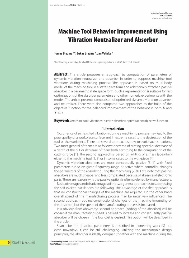
6 VOLUME 19, No. 4, 2015
Acta Mechanica Slovaca 19 (4): 6 - 12, 2015
* Corresponding author: Tomas Brezina, prof. RNDr. Ing. CSc., Phone: +420-541-142-295 E-mail address: [email protected]
Acta Mechanica SlovacaISSN 1335-2393
www.actamechanica.sk
Machine Tool Behavior Improvement Using Vibration Neutralizer and Absorber
Tomas Brezina 1*, Lukas Brezina 1, Jan Vetiska 1
1 Brno University of Technology, Faculty of Mechanical Engineering, Technicka 2, 616 69, Brno, Czech Republic
Abstract: The article proposes an approach to computation of parameters of dynamic vibration neutralizer and absorber in order to suppress machine tool vibrations during machining process. The approach is based on multi-body model of the machine tool in a state space form and additionally attached passive absorber in a parametric state space form. Such a representation is suitable for fast optimizations of the absorber parameters and other numeric experiments with the model. The article presents comparison of optimized dynamic vibration absorber and neutralizer. There were also compared two approaches to the build of the objective function for the balanced improvement of the behavior in both X and Y axis.
Keywords: machine tool; vibrations; passive absorber; optimization; objective function.
1. Introduction Occurrence of self-excited vibrations during a machining process may lead to the poor quality of a workpiece surface and in extreme cases to the destruction of the tool or the workpiece. There are several approaches how to avoid such situations. Two most general of them are as follows: decrease of cutting speed or decrease of a depth of the cut or decrease of them both according to the computation of the cutting force [1]. The second approach is based on adding of a mass (absorber) either to the machine tool [2, 3] or in some cases to the workpiece [4]. Dynamic vibration absorbers are most conceptually passive [5, 6] with fixed parameters tuned on given frequency range or active where controller changes the parameters of the absorber during the machining [7, 8]. Let’s note that passive absorbers are much cheaper and less complicated because of absence of electronic parts. These are reasons why the passive option is often preferred by manufacturers. Basic advantages and disadvantages of the two general approaches to suppressing the self-excited oscillations are following. The advantage of the first approach is that no constructional changes of the machine are required. On the other hand overall speed of the manufacturing process may be negatively influenced. The second approach requires constructional changes of the machine (mounting of the absorber) but the speed of the manufacturing process is increased. It is obvious from above: the second approach (adding of the absorber) will be chosen if the manufacturing speed is desired to increase and consequently passive absorber will be chosen if the low cost is desired. This option will be described in the article. Search for the absorber parameters is described in pioneering work [9] but even nowadays it can be still challenging. Utilizing the mechatronic design principles, the absorber is ideally designed together with the machine during the
Acta Mechanica SlovacaJournal published by Faculty of Mechanical Engineering - Technical University of Košice
7
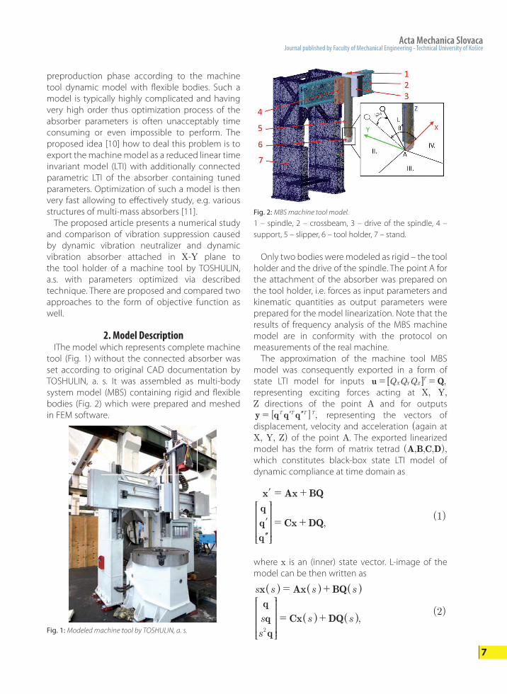
preproduction phase according to the machine tool dynamic model with flexible bodies. Such a model is typically highly complicated and having very high order thus optimization process of the absorber parameters is often unacceptably time consuming or even impossible to perform. The proposed idea [10] how to deal this problem is to export the machine model as a reduced linear time invariant model (LTI) with additionally connected parametric LTI of the absorber containing tuned parameters. Optimization of such a model is then very fast allowing to effectively study, e.g. various structures of multi-mass absorbers [11]. The proposed article presents a numerical study and comparison of vibration suppression caused by dynamic vibration neutralizer and dynamic vibration absorber attached in X-Y plane to the tool holder of a machine tool by TOSHULIN, a.s. with parameters optimized via described technique. There are proposed and compared two approaches to the form of objective function as well.
2. Model Description IThe model which represents complete machine tool (Fig. 1) without the connected absorber was set according to original CAD documentation by TOSHULIN, a. s. It was assembled as multi-body system model (MBS) containing rigid and flexible bodies (Fig. 2) which were prepared and meshed in FEM software.
Only two bodies were modeled as rigid – the tool holder and the drive of the spindle. The point A for the attachment of the absorber was prepared on the tool holder, i.e. forces as input parameters and kinematic quantities as output parameters were prepared for the model linearization. Note that the results of frequency analysis of the MBS machine model are in conformity with the protocol on measurements of the real machine. The approximation of the machine tool MBS model was consequently exported in a form of state LTI model for inputs Q Q Q ,u QX Y Z
T= =6 @representing exciting forces acting at X, Y, Z directions of the point A and for outputs
,[ ]y q q qT T T T= l m representing the vectors of displacement, velocity and acceleration (again at X, Y, Z) of the point A. The exported linearized model has the form of matrix tetrad (A,B,C,D), which constitutes black-box state LTI model of dynamic compliance at time domain as
,
q
q
q
Cx DQ= +
x Ax BQ= +l
l
m
R
T
SSSSSSSS
V
X
WWWWWWWW
( )1
Fig. 1: Modeled machine tool by TOSHULIN, a. s.
Fig. 2: MBS machine tool model.
1 – spindle, 2 – crossbeam, 3 – drive of the spindle, 4 – support, 5 – slipper, 6 – tool holder, 7 – stand.
where x is an (inner) state vector. L-image of the model can be then written as
,
s s s s
s
s
s s
x Ax BQ
q
q
q
Cx DQ2
= +
= +
^
^
^
^
^h
h
h
h
hR
T
SSSSSSSS
V
X
WWWWWWWW
( )2
8 VOLUME 19, No. 4, 2015
and in the simpler form as
.s
s
s s
q
q
q
Q2
a= ^ ^h h
R
T
SSSSSSSS
V
X
WWWWWWWW( )3
The frequency characteristic of dynamic compliance sa^ h by (3) between axis k and l at the point A could be expressed as
.jQ jq j
,k ll
ka ~
~
~=^^^
hhh
( )4
The model, representing the absorber as a white-box model, is described in its own coordinate system by the L-image of equation of motion
,m s b s k q s Q sA A A A A2 + + =^ ^ ^h h h ( )5
where mA means the mass of the absorber, bA is the damping, kA is the stiffness (these parameters are arranged to the vector of parameters p) and qA, sqA, s2qA are kinematic quantities. L-image of the absorber LTI ,s pAa ^ h therefore could keep known dependency on parameters m b kp A A A= 6 @ . Taking into account a prismatic joint between the machine tool and absorber, these are then mutually influenced by additional forces
,s Q sQi iA^ ^h h according to
,
s
s
s s s
q s s Q s Q s
q
q
q
Q Qi
A A AiA
2
a
a= +
= +^
^
^
^
^
^
^
^
^h
h
h
h
h
hh
hh
R
T
SSSSSSSS
V
X
WWWWWWWW( )6
the white-box model of the interface describing the interaction between the machine and the absorber is obtained as
,Q m s
m m s m s qQ
q h
q hiA
i
A T
DA A A A
2
2 2=-
- + -^ ^h h= =G G ( )7
where mDA is frame mass of the absorber and
cos cos cos sin sinh A A A A A Ti i i{ {= 6 @ describes
the orientation of the coordinate system of the absorber model with respect to the coordinate system of the basic model via spherical angles (Fig. 2). The complete model of the machine tool with
the absorber connected at the point A through the interface, denoted ,s pCa ^ h , now with the vector of parameters ,m m b kp D
A A A A A Ai {= 6 @ see (5,7), represents grey-box model with matrix tetrad ., , ,A p B p C p D pC C C C^ ^ ^ ^ ^h h h hh Note that the complete model is implemented to be tunable through the vector of parameters p. The computation time of frequency responses for specific parameters of grey-box LTI is significantly faster than the same computation performed directly on the complete MBS model of the machine with the absorber. On the other hand it is often accompanied by a partial loss of the response accuracy. The computation time of the 12 frequency responses from the state LTI was in this particular case about 30x faster than in MBS software with the equality of the responses up to 5%. Let’s note that the exported black-box model of the machine tool a presents the linear approximation which is also influenced by consequent reduction of its order.
3. Search for the Optimal Absorber Parameters Significantly faster computation time of frequency responses for specific parameters of grey-box LTI model with tunable parameters offers wide range of possibilities for algorithm applications requiring large amounts of such computations. The minimization is one example of such computations. The optimal parameters of the absorber p
opt
were searched via a minimization popt
=arg min g(p) with constrained scalar objective function g(p). The choice of the specific objective function significantly influences final values of searched parameters. During the objective function assembly, it was necessary to take into account that the LTI model of the machine tool was based on the MBS model containing the flexible bodies. The axes of the machine are mutually influenced because of that fact, thus it is not sufficient to improve the behavior of one of them but it is necessary to introduce to the objective function a requirement for the improvement in all of axes. The Z axis was not contained in the objective function because transfer compliances to/from it are too small to influence the minimization. It was just slowing down the computation. As an initial objective function the higher from
Acta Mechanica SlovacaJournal published by Faculty of Mechanical Engineering - Technical University of Košice
9
maxima of the frequency response magnitudes in X, Y axes of the dynamic compliance aC (s,p)inside the studied frequency range 1≤f≤1000[Hz] was used, related to the same without the absorber a(s), see (3), i.e.
max max
max max ,g
j f
j fp
p
2
2
,.
,.
k X Y fk k
k X Y fk kC
a r
a r=
=
=^
`
`
^
^h
h
h
j
j( )8
The objective function (8) guarantees, for properly constrained parameters, improvement (reduction of the maximum response magnitude) of the X or Y axis but it does not guarantee simultaneous improvement in both of axes. That was the reason why the objective function (9), which should guarantee simultaneous improvement in both of axes, was proposed and checked.
maxmax
max ,g
j f
j fp
p
2
2
, .
.
k X Yf
k k
fk kC
a r
a r=
=^ f
^
^h
h
hp ( )9
Note that the objective function (9) differs from (8) by norming the magnitudes of each of axes separately. The maximum is then taken from the results.
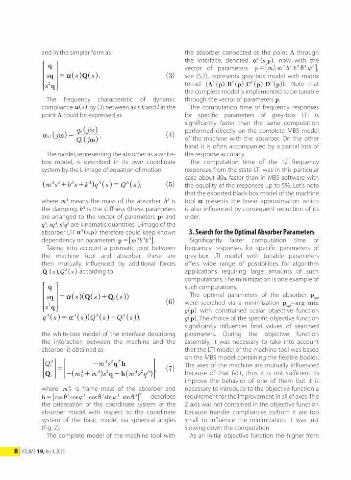
4. Numeric Experiments The numeric experiments were focused on comparison of the dynamic vibration neutralizer (DVN, bA=0N.s/mm) and dynamic vibration absorber (DVA, bA>0N.s/mm), both in two alternatives of mA, mA≤5kg and mA≤10kg, as well as on influence comparison of objective functions by (8) and (9). To keep the realization passive, parameters were optimized in the following ranges: kA≤5.103 N/mm, bA≤5 N.s/mm and for the X-Y orientation of the absorber 0°≤ qA≤360°, jA=0°. The parameters were initially searched without considered frame mass for the improvement analysis. The parameters were finally completed with the frame mass – the parameter expressing the overall weight of the absorber parts which does not directly influence the vibration suppression.4.1. Dynamic vibration neutralizer The DVN is considered with bA=0 N.s/mm and m kg0D
A = . The advantage of such dynamic system is its simpler feasibility against DVA. The results are
presented in Fig. 3 and Fig. 4.
Fig. 3: DVN magnitude response, objective function (8).
Fig. 4: DVN magnitude response, objective function (9).
:
:
, ,
, ,
. /
. /
m m kg k N mm
m m kg k N mm
5 5 47 3 121
10 9 8 831 138
kg
kg
AoptA
optA
optA
AoptA
optA
optA
c
c
#
#
i
i
= = =
= = =
:
:
, ,
, ,
. /
. /
m m kg k N mm
m m kg k N mm
5 5 19 9 95
10 4 3 512 346
kg
kg
AoptA
optA
optA
AoptA
optA
optA
c
c
#
#
i
i
= = =
= = =
The obtained results of the DVN were not convincing. DVN had almost no influence on
10 VOLUME 19, No. 4, 2015
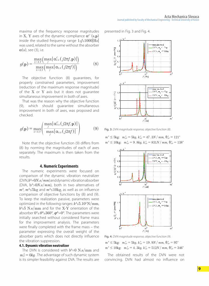
X axis. The maximal magnitude in Y axis was decreased by ca. 20%; however another resonant magnitude appeared in the both responses. Thus DVA parameters were optimized and checked during the next stage. Let’s note that even objective function (9) did not bring expected effect.4.2. Dynamic vibration absorber A dynamic vibration absorber works except non–zero parameters mA, kA also with non–zero bA. Therefore DVA is more structurally complicated than the DVN because it is necessary to implement the damping bA. Thus the absorber was considered with bA>0N.s/mm and m kg0D
A = in this stage. Results are presented in the Fig. 5 and Fig. 6.
Fig. 5: DVA magnitude response, objective function (8).
: 0
: 9 .
, b ,
,
, b ,
,
. /
/
. /
/
m m kg N mm
k N mm
m m kg N mm
k N mm
5 5 2 3
1250 88
10 9 4 03
2530 138
kg
kg
AoptA
optA
optA
optA
AoptA
optA
optA
optA
c
c
#
#
i
i
= =
= =
= =
= =
The outcomes obtained with DVA are more encouraging than with DVN. The maximal magnitudes were significantly reduced in both axes and no additional resonance magnitude was observed. Let’s point out the substantial improvement of the results, especially in the case of use of the objective function (9), where, for .m kg9 2opt
A = , the
Fig. 6: DVA magnitude response, objective function (9).
: 91
320
: 2
, ,
,
, ,
,
. /
/
. /
/
m m kg b N mm
k N mm
m m kg b N mm
k N mm
5 5 1
1 252
10 9 2
1660 62
kg
kg
AoptA
optA
optA
optA
AoptA
optA
optA
optA
c
c
#
#
i
i
= =
= =
= =
= =
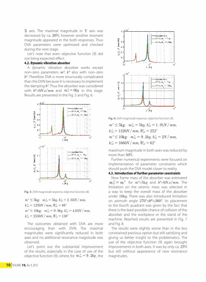
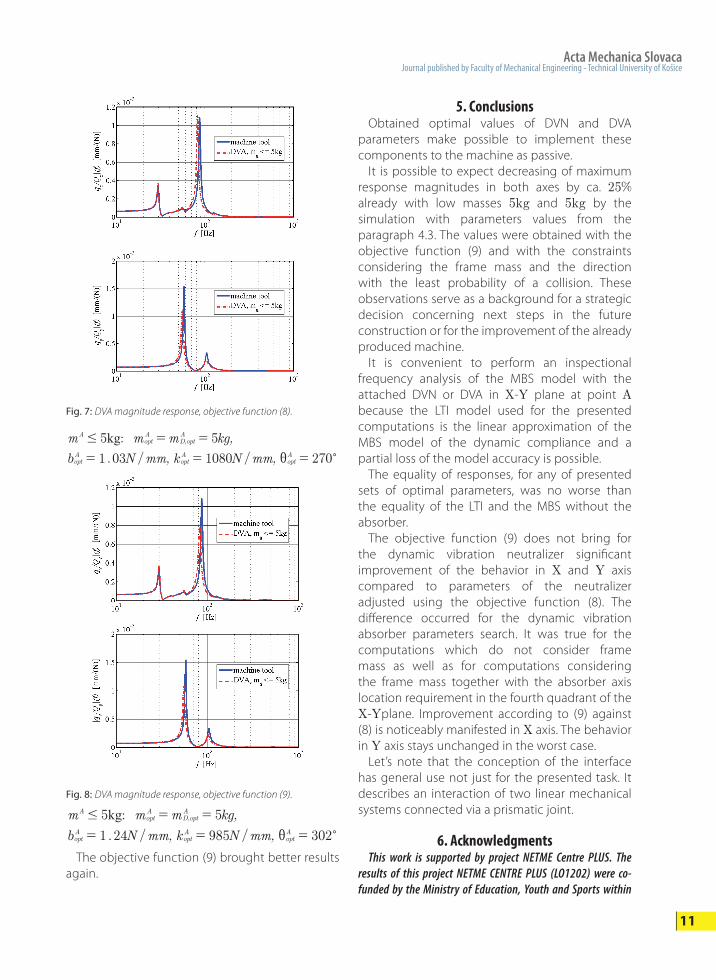
maximum magnitude in both axes was reduced by more than 50%. Further numerical experiments were focused on implementation of parameter constraints which should push the DVA model closer to reality.4.3. Introduction of further parameter constraints Now frame mass of the absorber was estimated m mD
A A= for mA>5kg and bA>0N.s/mm. The limitation on the seismic mass was selected in a way to keep the overall mass of the absorber under 10kg. There was also introduced limitation on azimuth angle 270°≤qA≤360°. Its placement to the fourth quadrant was given by the fact that there is the least possible chance of collision of the absorber and the workpiece or the stand of the machine. Reached results are presented in Fig. 7 and Fig. 8. The results were slightly worse than in the less constrained previous option but still satisfying and giving us better insight to the problematics. The use of the objective function (9) again brought improvements in both axes. It was by only ca. 25% but still without appearance of new resonance magnitudes.
Acta Mechanica SlovacaJournal published by Faculty of Mechanical Engineering - Technical University of Košice
11
5. Conclusions Obtained optimal values of DVN and DVA parameters make possible to implement these components to the machine as passive. It is possible to expect decreasing of maximum response magnitudes in both axes by ca. 25% already with low masses 5kg and 5kg by the simulation with parameters values from the paragraph 4.3. The values were obtained with the objective function (9) and with the constraints considering the frame mass and the direction with the least probability of a collision. These observations serve as a background for a strategic decision concerning next steps in the future construction or for the improvement of the already produced machine. It is convenient to perform an inspectional frequency analysis of the MBS model with the attached DVN or DVA in X-Y plane at point A because the LTI model used for the presented computations is the linear approximation of the MBS model of the dynamic compliance and a partial loss of the model accuracy is possible. The equality of responses, for any of presented sets of optimal parameters, was no worse than the equality of the LTI and the MBS without the absorber. The objective function (9) does not bring for the dynamic vibration neutralizer significant improvement of the behavior in X and Y axis compared to parameters of the neutralizer adjusted using the objective function (8). The difference occurred for the dynamic vibration absorber parameters search. It was true for the computations which do not consider frame mass as well as for computations considering the frame mass together with the absorber axis location requirement in the fourth quadrant of the X-Yplane. Improvement according to (9) against (8) is noticeably manifested in X axis. The behavior in Y axis stays unchanged in the worst case. Let’s note that the conception of the interface has general use not just for the presented task. It describes an interaction of two linear mechanical systems connected via a prismatic joint.
6. Acknowledgments This work is supported by project NETME Centre PLUS. The results of this project NETME CENTRE PLUS (LO1202) were co-funded by the Ministry of Education, Youth and Sports within
Fig. 7: DVA magnitude response, objective function (8).
:
03
,
, ,. / /
m m m kg
b N mm k N mm
5 5
1 1080 270
kg ,A
optA
D optA
optA
optA
optA c
#
i
= =
= = =
Fig. 8: DVA magnitude response, objective function (9).
:
24
,
, ,. / /
m m m kg
b N mm k N mm
5 5
1 985 302
kg ,A
optA
D optA
optA
optA
optA c
#
i
= =
= = =
The objective function (9) brought better results again.
12 VOLUME 19, No. 4, 2015
[11] Brezina, T., Brezina, L., Vetiska, J., Marek J. (2015). Initial As-
sessment of Multi-mass Absorber Influence on Machine
Tool Vibrations. International Conference on Mechatronics
2015, In print.
Biographical notesTomas Brezina, prof. RNDr. Ing. CSc. He received M.S. degree in electrical engineering from Brno Technical University, Czech Republic in 1978, CSc. degree there in 1985 and in the same year doctorate RNDr. in cybernetics, computer sci-ence and systems theory from Jan Evangelista Purkyne University in Brno, Czech republic. He is a professor of the Institute of Automation and Computer Science at the Faculty of Mechanical Engineering at the Brno Technical University, Czech Republic. His research interests include modeling and control of mechatronic sys-tems and robotics inclusive utilizing artificial intelligence methods. He is author or co-author of more than 200 journal and conference papers on these topics.Lukas Brezina, Ing. PhD. He received M.S. degree in mechanical engineering - mechatronics from Brno University of Technology, Czech republic in 2006 and Ph.D. degree in Applied Sciences in Engineering from Brno University of Technol-ogy, Czech republic in 2010. He is a senior lecturer of the Institute of Solid Mechan-ics, Mechatronics and Biomechanics at the Faculty of Mechanical Engineering at the Brno University of Technology, Czech republic. His research interests include modeling of mechatronic systems and robotics. He is author and co-author of almost 30 journal and conference papers on these topics.Jan Vetiska, Ing. PhD. He received M.S. degree in mechanical engineering - computer science and automation from Brno University of Technology, Czech republic in 2008 and Ph.D. degree in Applied Sciences in Engineering from Brno University of Technology, Czech republic in 2013. He is a senior lecturer of the In-stitute of Production Machines, Systems and Robotics at the Faculty of Mechani-cal Engineering at the Brno University of Technology, Czech republic. His research interests include modeling of mechatronic systems and measuring of geometric accuracy of machine tools. He is author and co-author of 31 journal and confer-ence papers on these topics.
the support programme „National Sustainability Programme I“.
7. References and Notes[1] Tlusty, J. (1986). Dynamics of High-speed Milling. Journal of
Engineering for Industry, vol. 108, no. 2, pp. 59 – 67.
[2] Chung, B., Smith, S., Tlusty J. (1997). Active Damping of
Structural Modes in High Speed Ma-chine Tools. Journal of
Vibration and Control, vol. 3, no. 3, 279–295.
[3] Leigh, E.P., Tlusty, J., Smith, S. (2000). Advanced Machining
Techniques on Titanium Rotor Parts. American Helicopter
Society 56th Annual Forum, pp. 1 – 19.
[4] Sims, N. D. (2007). Vibration Absorbers for Chatter Suppres-
sion: A New Analytical Tuning Methodology. Journal of
Sound and Vibration, vol. 301, no. 3, pp. 592–607.
[5] Tarng, Y.S., Kao, J.Y., Lee, E.C. (2000). Chatter suppression in
turning operations with a tuned vibration absorber. Jour-
nal of Materials Processing Technology, vol. 105, no. 1, pp.
55–60.
[6] Rivin, E.I., Kang, H. (1992). Enhancement of dynamic stabil-
ity of cantilever tooling structures. International Journal of
Machine Tools & Manufacture, vol. 32, no. 4, pp. 539 – 561.
[7] Pratt, J.R., Nayfeh, A.H. (2001). Chatter control and stability
analysis of a cantilever boring bar under regenerative cut-
ting conditions. Philosophical Transactions of the Royal So-
ciety of London, vol. 359, no. 1781, pp. 759 – 792.
[8] Brecher, C., Schulz, A., Weck M. (2005). Electrohydraulic ac-
tive damping system. CIRP Annals—Manufacturing Tech-
nology, vol. 54, no. 1, pp. 389 – 392.
[9] Den Hartog, J.P. (1956). Mechanical Vibrations. McGraw-Hill,
New York (1956)
[10] Brezina, T., Brezina, L., Stetina, J., Marek J. (2014). Design of
Optimal Parameter Values of Mechatronic System with Flex-
ible Bodies Using a Block Model. 16th International Confer-
ence on Mechatronics - Mechatronika 2014, pp. 301-307.