Embed Size (px)
Citation preview
Machine Monitoring Application GuideUsing a TL70 Modular Tower Light with a wireless radio base improves machine monitoring and overall equipment effectiveness(OEE) by expanding available data beyond the local indication a standard tower light provides.
Beyond local indication, each TL70 can provide the remote status of each light module, track the cumulative time ON for each lightmodule, count the number of times each module transitions from the OFF to ON state, and count parts. This system provides theinformation necessary to react quickly to system changes and drive efficiency improvements based on data that was previouslyunavailable.
The following guide demonstrates how to bind the wireless tower lights to the DXM and load a preconfigured XML file and script tocollect data from up to 24 wireless tower lights. The XML file only requires some minor modifications to be customized for any site.
Guide Features and Benefits
Machine Monitoring Monitor machine inputs with up to four tower light modules (on up to 24 tower lights) and eight states (flashing or solid foreach light module).
Up Time Track cumulative ON time for each light module for both flashing or solid independently.
Event Counters Count the number of times each light module transitions from OFF to ON for both flashing or solid independently.
Parts Counting Count parts produced or rejected using internal 32-bit register in the TL70 Tower Light.
Remote Master Light Use a master light to show combined status of all light modules.
Time Stamped Logging Time stamped logging of light statuses, timers, counts, and part counts to a local SD memory card.
SMS Text and Email Alerts Generate SMS text and/or email alerts based on specific events.
Efficiency Metrics Produce efficiency metrics with provided data (Avg. Availability, Production Speed, Production Quality, etc.).
Cloud Monitoring Push data to Cloud Webserver or PLC (via LAN or Cellular connection) for remote viewing, alerting, and logging.
Equipment
Model Description
TL70DXN9XXXQ orTL70DXN2XXXQ (XXX is anycombination of light colors)
EZ-LIGHT TL70 Wireless Modular Tower Light;
Select either the 900 MHz or 2.4 GHz ISM radio to match theDXM's ISM radio
DXM700-B1R1 or DXM700-B1R3
DXM700 Wireless Controller; select either 900 MHz or 2.4 GHzISM radio to match the TL70's ISM radio.
The DXM1200 models will also work in this application. To orderthe DXM1200, relace the DXM700 in the model with DXM1200.
Step 1: Bind the TL70 to the DXM and Assign the Device IDBinding the TL70s to the DXM establishes a secure connection between them and assigns a specific network address to eachTL70 in the wireless network.
1. Apply power the TL70s.
TL70s require a constant power source to maintain wireless communications with the DXM, unlike typical tower lights thatuse only machine power when lighting.
2. Apply power to the DXM.3. On the DXM: Use the arrow button to select the ISM Radio menu on the LCD. Press Enter.4. Select Binding and press Enter.
Machine Monitoring Application Guide
Original Documentb_4437437 Rev. D
21 September 2020 Technical Note
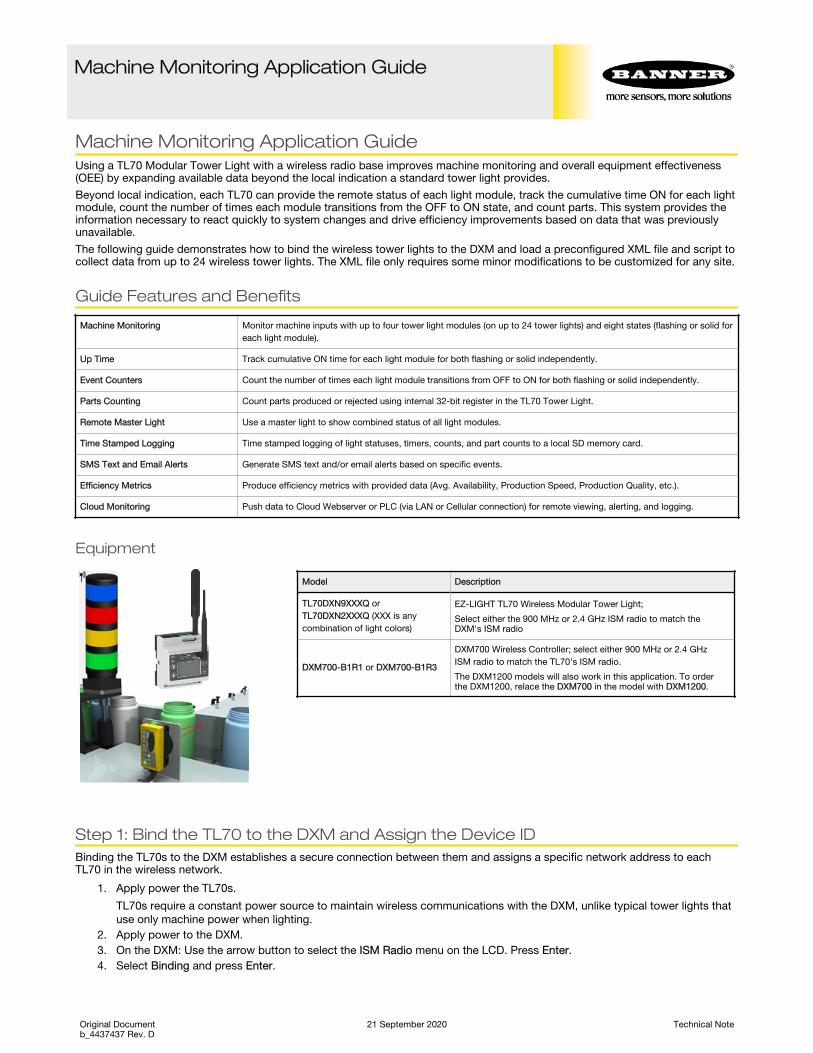
5. Select Bind to > 1 (the first Node) and press Enter.6. On TL70 Node 1: Remove the base section by grasping the lighting modules and twisting the base clockwise.7. Triple-click the binding button.
DIP Switches
BindingPush Button
LED
The LED flashes four times after it binds to the DXM. This Node is now bound as Node ID 1. Label the TL70 for futurereference.
8. Reconnect the TL70’s base to its light modules.9. On the DXM: Press Back to return to the main menu.10. To bind additional TL70s, select Bind to > 2 and press Enter.11. On TL70 Node 2: Repeat steps 6 through 9.
If more TL70s are being used in the system, continue binding until all TL70s are bound to the DXM with each having theirown Node ID.
12. When you are finished binding, press Back on the DXM until the DXM returns to the main menu.
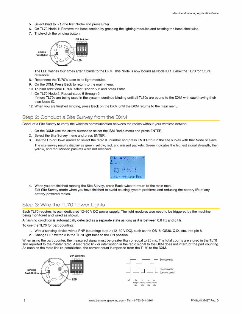
Step 2: Conduct a Site Survey from the DXMConduct a Site Survey to verify the wireless communication between the radios without your wireless network.
1. On the DXM: Use the arrow buttons to select the ISM Radio menu and press ENTER.2. Select the Site Survey menu and press ENTER.3. Use the Up or Down arrows to select the radio ID number and press ENTER to run the site survey with that Node or slave.
The site survey results display as green, yellow, red, and missed packets. Green indicates the highest signal strength, thenyellow, and red. Missed packets were not received.
4. When you are finished running the Site Survey, press Back twice to return to the main menu.
Exit Site Survey mode when you have finished to avoid causing system problems and reducing the battery life of anybattery-powered radios.
Step 3: Wire the TL70 Tower LightsEach TL70 requires its own dedicated 12–30 V DC power supply. The light modules also need to be triggered by the machinebeing monitored and wired as shown.
A flashing condition is automatically detected as a separate state as long as it is between 0.8 Hz and 6 Hz.
To use the TL70 for part counting:
1. Wire a sensing device with a PNP (sourcing) output (12–30 V DC), such as the QS18, QS30, Q4X, etc, into pin 8.2. Change DIP switch 3 in the TL70 light base to the ON position.
When using the part counter, the measured signal must be greater than or equal to 25 ms. The total counts are stored in the TL70and reported to the master radio. A lost radio link or interruption in the radio signal to the DXM does not interrupt the part counting.As soon as the radio link re-establishes, the correct count is reported from the TL70 to the DXM.
DIP Switches
BindingPush Button
LED
Event counts
Event counter does not count
t = 0 1xsample
rate
2xsample
rate
3xsample
rate
4xsample
rate
Machine Monitoring Application Guide
2 www.bannerengineering.com - Tel: +1-763-544-3164 P/N b_4437437 Rev. D

The 5-pin base allows a maximum of three modules
Module
M2
M3
M1
3
4
1
2
5
12–30 V dc
1
453
2
1 = brown2 = white3 = blue4 = black5 = grayM1 = Module 1M2 = Module 2M3 = Module 3
The 8-pin base allows for four modules and part counting
7
6
2
1
5
4
8
3
12–30 V dc
Module
M1
M2
M3
M4
M5
M6
5
671
8
234
1 = white2 = brown3 = green4 = yellow5 = gray6 = pink7 = blue8 = red (event counter input, if enabled)M1 = Module 1M2 = Module 2M3 = Module 3M4 = Module 4M5 = Module 5M6 = Module 6
Step 4: Configure the SystemTo customize the system to an actual application, some basic modification to the template files is necessary.
There are two files uploaded to the DXM: the XML file sets the DXM’s initial configuration and the ScriptBasic file reads the statusof light modules, controls the counting of each light, establishes a reset function for each TL70s timers and counts, and organizesthe information in logical and easy to find registers in the DXM.
Loading these files and making adjustments requires Banner’s DXM Configuration Software and the machine monitoring filesavailable via in the links below.
1. Download the preconfigured files from the DXM or Wireless TL70 series pages.2. Extract the ZIP files into a folder on your computer. Note the file location.3. Connect the DXM, using the USB cable supplied with the DXM, to a computer containing the DXM Configuration Software
or download the software and install it on a computer.4. Launch the software.5. Load the Machine Monitoring XML file (TL70) by going to File > Open and choosing the XML configuration file.6. Connect to the DXM.
a) Go to Select Mode screen.b) Select Serial and then select the COM port that the USB cable is plugged into.c) Click Connect. If you are unsure which COM port is being used and multiple ports appear, attempt to connect to each
one until you are successful.7. Go to Settings > Scripting to upload the Machine Monitoring XML file (TL70). Click Upload File and select the .sb file.8. Save the XML file any time the XML has been changed because the tool does not autosave.
Machine Monitoring Application Guide
P/N b_4437437 Rev. D www.bannerengineering.com - Tel: +1-763-544-3164 3
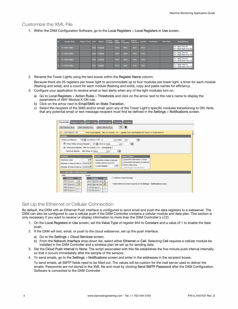
Customize the XML File1. Within the DXM Configuration Software, go to the Local Registers > Local Registers in Use screen.
2. Rename the Tower Lights using the text boxes within the Register Name column.
Because there are 25 registers per tower light to accommodate up to four modules per tower light, a timer for each module(flashing and solid), and a count for each module (flashing and solid), copy and paste names for efficiency.
3. Configure your application to receive email or text alerts when any of the light modules turn on.
a) Go to Local Registers > Action Rules > Thresholds and click on the arrow next to the rule's name to display theparameters of ANY Module X ON rule.
b) Click on the arrow next to Email/SMS on State Transition.c) Select the recipient of the SMS and/or email upon any of the Tower Light’s specific modules transitioning to ON. Note
that any potential email or text message recipient must first be defined in the Settings > Notifications screen.
Set Up the Ethernet or Cellular ConnectionBy default, the DXM with an Ethernet Push interface is configured to send email and push the data registers to a webserver. TheDXM can also be configured to use a cellular push if the DXM Controller contains a cellular module and data plan. This section isonly necessary if you want to receive or display information to more than the DXM Controller's LCD.
1. On the Local Registers in Use screen, set the Value Type of register 844 to Constant and a value of 1 to enable the datapush.
2. If the DXM will text, email, or push to the cloud webserver, set up the push interface.
a) Go to the Settings > Cloud Services screen.b) From the Network Interface drop-down list, select either Ethernet or Cell. Selecting Cell requires a cellular module be
installed in the DXM Controller and a wireless plan be set up for sending data.3. Set the Cloud Push Interval to None. The script associated with this file establishes the five-minute push interval internally,
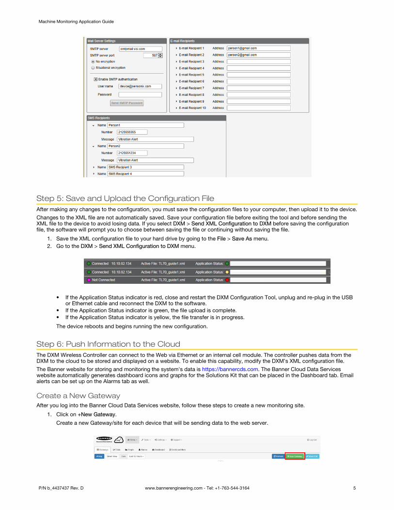
so that it occurs immediately after the sample of the sensors.4. To send emails, go to the Settings > Notifications screen and enter in the addresses in the recipient boxes.
To send emails, all SMTP fields need to be filled out. The values will be custom for the mail server used to deliver theemails. Passwords are not stored in the XML file and must by clicking Send SMTP Password after the DXM ConfigurationSoftware is connected to the DXM Controller.
Machine Monitoring Application Guide
4 www.bannerengineering.com - Tel: +1-763-544-3164 P/N b_4437437 Rev. D
Step 5: Save and Upload the Configuration FileAfter making any changes to the configuration, you must save the configuration files to your computer, then upload it to the device.
Changes to the XML file are not automatically saved. Save your configuration file before exiting the tool and before sending theXML file to the device to avoid losing data. If you select DXM > Send XML Configuration to DXM before saving the configurationfile, the software will prompt you to choose between saving the file or continuing without saving the file.
1. Save the XML configuration file to your hard drive by going to the File > Save As menu.2. Go to the DXM > Send XML Configuration to DXM menu.
• If the Application Status indicator is red, close and restart the DXM Configuration Tool, unplug and re-plug in the USBor Ethernet cable and reconnect the DXM to the software.
• If the Application Status indicator is green, the file upload is complete.• If the Application Status indicator is yellow, the file transfer is in progress.
The device reboots and begins running the new configuration.
Step 6: Push Information to the CloudThe DXM Wireless Controller can connect to the Web via Ethernet or an internal cell module. The controller pushes data from theDXM to the cloud to be stored and displayed on a website. To enable this capability, modify the DXM’s XML configuration file.
The Banner website for storing and monitoring the system's data is https://bannercds.com. The Banner Cloud Data Serviceswebsite automatically generates dashboard icons and graphs for the Solutions Kit that can be placed in the Dashboard tab. Emailalerts can be set up on the Alarms tab as well.
Create a New GatewayAfter you log into the Banner Cloud Data Services website, follow these steps to create a new monitoring site.
1. Click on +New Gateway.
Create a new Gateway/site for each device that will be sending data to the web server.
Machine Monitoring Application Guide
P/N b_4437437 Rev. D www.bannerengineering.com - Tel: +1-763-544-3164 5

2. Enter a site name.3. Under the Options column, click +.
Detailed information about your new site displays.4. Copy the Site ID number shown on the dashboard.
The Site ID number created by the web server is a required parameter in the configuration setup of the DXM. The Site ID isthe address the webserver uses to store the data pushed from the DXM.
5. Click Save.
Configure the DXM to Push Information to the Cloud1. Within the DXM Configuration Software, go to the Settings > Cloud Services screen.2. Set the Server name/IP to push.bannercds.com.3. In the Web Server section, keep the Gateway ID is drop-down selection as GUID.4. Use the File > Save menu to save the XML file to your hard drive.5. Send the updated XML to the DXM Controller using the DXM > Send XML COnfiguration to DXM menu.
Upload the XML Configuration File to the WebsiteTo upload an XML configuration file to the website, follow these instructions.
1. At the webserver, select the Home screen.
2. On the row displaying your new site, click the Edit Gateway (pencil) icon.3. Select Update XML.4. Click Choose File and select the file that was just updated to the DXM and click Save.
Figure 1. Example file selection screen that may not represent your specific kit
After the XML file is loaded into the webserver, the webserver uses the register names and configurations defined in theconfiguration file.
5. Click on the Site Name link to go to the configured registers to see the values uploaded by the DXM.The same XML configuration files is now loaded on both the DXM and the Website. After some time, the data should beseen on the website.
Completing these steps creates continuity between the site created on the website with the DXM used in the field. The DXMpushes data to the website, which can be viewed at any time.
Refer to the Banner Cloud Data Services Instruction Manual to review all the features available for monitoring, comparing data, andestablishing warnings/alarms on the website. To access a demo version of the website please contact your local Banner distributorand follow the instructions in the technical note: Connecting to the Banner Cloud Data Services Demo Site for modified instructionson how to send data to the demo site.
Additional Information
Reset the Timer and CountsEach TL70 in the system has a reset register that is available from the DXM’s LCD. Setting this register to 1 resets all the countsand timers on that particular TL70.
1. On the DXM: Use the arrows to select Registers.
The registers are labeled TL X Reset (where X is the TL70 Node ID you want to reset).
Machine Monitoring Application Guide
6 www.bannerengineering.com - Tel: +1-763-544-3164 P/N b_4437437 Rev. D

2. Select the appropriate register to reset.3. Click the Enter button.4. Change the value to 1 then click Enter three times.
The reset register automatically returns to zero after the TL70s reset.
Create a Master LightLocal Registers 794–797 are used to OR each module independently for all the TL70s (for example, 794 is 1 when ANY tower lightin the system has module #1 on or flashing). A master light can be used as one of the 24 in the system to reflect these OR’dstatuses.
1. On the DXM Configuration Software: Go to Register Mapping > Write Rules.2. Select Add Write Rule and map four registers starting at 794 to slave ID #1 at the four output registers for the Master Light.
The register number for the master light outputs is N × 16 + 9, where N is the Node ID of the master light. The exampleshows the setup for the Master Light on Node ID 10 (10 × 16 + 9 = 169).
Configure Time-Stamped LoggingBy default, the files associated with this guide trigger a time-stamped event in the log each time a tower light module changesstatus or once per hour if no changes have occurred. Change the hourly log rate by modifying the value in register 842, which islisted in seconds. Note this also modifies the cloud push rate if it is used. To setup time-stamped logging, follow these steps.
1. Go to the Local Registers > Modify Multiple Registers screen.2. Click Reset Form.3. From the SD Card Logging drop-down list, select Change.4. Select Log 1 in the drop-down list that appears to the right.5. Set the Starting Register to 1 and the Ending Register to the value equal to 25 × Number of tower lights in the system (ex.
Ending Register 300 for 12 tower lights).6. Click Change Registers on the bottom right portion of the section.
Save a Log File1. Connect the DXM to the computer using USB or Ethernet.2. Connect the DXM Configuration Software to the DXM using the Select Mode screen.3. Go to the Settings > Logging screen.4. Click Refresh List.5. In the Log File Management window, select the file to save.6. Click Save selected file to save the file to a folder on your computer.
Local RegistersWhere N represents the TL70 Node ID.
Local Register # Description
Tower Light Module Status
1 + 25 × (N – 1) Module 1 Status (ON/OFF/Flash)
2 + 25 × (N – 1) Module 2 Status (ON/OFF/Flash)
3 + 25 × (N – 1) Module 3 Status (ON/OFF/ Flash)
4 + 25 × (N – 1) Module 4 Status (ON/OFF/Flash)
Tower Light Module Timers
5 + 25 × (N – 1) Module 1 Time ON (Minutes)
6 + 25 × (N – 1) Module 2 Time ON (Minutes)
7 + 25 × (N – 1) Module 3 Time ON (Minutes)
8 + 25 × (N – 1) Module 4 Time ON (Minutes)
Tower Light Module Count
9 + 25 × (N – 1) Module 1 Count
10 + 25 × (N – 1) Module 2 Count
11 + 25 × (N – 1) Module 3 Count
Machine Monitoring Application Guide
P/N b_4437437 Rev. D www.bannerengineering.com - Tel: +1-763-544-3164 7

Local Register # Description
12 + 25 × (N – 1) Module 4 Count
Tower Light Module Timers
13 + 25 × (N – 1) Module 1 Flash Time ON (Minutes)
14 + 25 × (N – 1) Module 2 Flash Time ON (Minutes)
15 + 25 × (N – 1) Module 3 Flash Time ON (Minutes)
16 + 25 × (N – 1) Module 4 Flash Time ON (Minutes)
Tower Light Module Count
17 + 25 × (N – 1) Module 1 Flash Count
18 + 25 × (N – 1) Module 2 Flash Count
19 + 25 × (N – 1) Module 3 Flash Count
20 + 25 × (N – 1) Module 4 Flash Count
Part Count 21 + 25 × (N – 1) Part Count
Tower Light All Modules OFF22 + 25 × (N – 1) All OFF Status
23 + 25 × (N – 1) All OFF Timer
Tower Light RF Connection Status24 + 25 × (N – 1) Connection Status
25 + 25 × (N – 1) Connection Status Timer
Bit-Packed Module Status 601–624 Module Status bit-packed for web push
Read Rule Module Statuses
625–648 Read Module 1 Statuses
649–672 Read Module 2 Statuses
673–696 Read Module 3 Statuses
697–720 Read Module 4 Statuses
TL70 Resets 770–793 TL70 Timer and Count Reset
OR'd Alerts
794 Any Module 1 active
795 Any Module 2 active
796 Any Module 3 active
797 Any Module 4 active
Read Rule Connection Status 800–823 Read TL Connection Status
Connection Status Bit-Packed 826 Connection Status bit-packed for web push
Log Timer Constant 842 Time in seconds for Log and Cloud Push
Log Timer 843 Log Timer
Log Trigger 844 Trigger to Log/Cloud Push
Cloud Push 851 Enable cloud pushing from the script (0/1)
Part Count Push 852 Enable pushing of part counts (0/1)
First Run 853 Nonvolatile register used for initial setup by script
Delay Mode 854 Enable 4 second script loop delay for troubleshooting
Machine Monitoring Application Guide
© Banner Engineering Corp. All rights reserved