Embed Size (px)
Citation preview

Machine Learning Solutions for an Autonomous Vehicle
Jagannath AghavCollege of Engineering [email protected]
Rinku NemadeCollege of Engineering Pune
Apoorva NitsureCollege of Engineering Pune
Abstract— Autonomous vehicles use and produce enormousamount of data.The use and analysis of data for safety and reli-ability in such cars is a critical aspect. A complex decision basedmechanism is vital to ensure safe navigation for autonomousvehicles in the uncertain environment. Pedestrian detection isnecessary as human safety is of utmost importance in today’surban traffic conditions. Vehicle detection is paramount to avoidcollisions leading to accidents. For this, autonomous cars mustfollow traffic rules and regulations to ensure smooth traffic.In this paper, we focus on detection of pedestrians, vehiclesand road signs using image processing and machine learning.To ensure disciplined driving in the world of autonomous cars,speed control according to the terrain type needs to be specified.We have proposed lane detection and speed control algorithmsas well.
Index Terms— HOG(Histogram Oriented Gradient),SVM(Support Vector Machine), Haar cascade, NMS(NonMaximum Suppression), LIDAR(Laser Illuminated DetectionAnd Ranging), IRC (Indian Road Congress), MLP(MultilayerPerceptron), RBF(Radial Basis Function)
I. INTRODUCTION
Autonomous cars are now a reality. The need of thehour is to reliably and accurately detect obstacles and avoidcollision. For instance, Uber has recently launched selfdriving cars as a pilot program in Pittsburgh. But still theyare nowhere near full autonomy and face problems withidentification of suddenly disappearing objects, bridges anddealing with other human drivers.
Active and passive are two approaches for obstacle detec-tion. Active methods include use of sensors whereas passivemethods use measurements of the scene e.g. camera images.Passive methods are advantageous as they work in most ofthe weather and lighting conditions, with a high resolution.Apart from that, cameras require less investment.
Obstacles with respect to a car generally include othercars, pedestrians, cyclist, road-signs, vegetation, animals,traffic signals, speed breakers. In this paper, we focus onthree types of obstacles: cars, pedestrians, road signs.
Autonomous vehicles need to adjust their speed accordingto traffic, weather and road conditions. In this paper, wehave discussed speed control for different terrains only. Asterrain detection is more accurate using passive methods wehave proposed a speed control algorithm which uses real timeLIDAR readings.
Additionally we propose a lane detection algorithm usinga connected component scheme.
II. PEDESTRIAN DETECTION
We suggest that pedestrian detection be done using HOGdescriptors and a linear SVM model for classification.[15]
A. Histogram Oriented Gradient
HOG descriptors are used to extract features from theimages. HOG descriptors carry out gradient computation,object binning and lastly extracting descriptors from blocks.This is an alternative to Haar Cascade classifiers i.e. Viola-Jones detectors[9]. HOG descriptors were originally inventedfor human detection and currently give the most accuratefeatures from images. As haar cascade features are best fortexture identification. HOG features are most suitable in thecase of human identification from images. There are six stepsinvolved in the process of training an object detector usingHOG. The steps are as follows:
Algorithm 1 Training an object detector for HOG1: Extraction of HOG descriptors from positive samples
from the training data.2: Extraction of descriptors from negative samples of train-
ing data which is generally greater than the positivesamples in previous step.
3: Using above samples train SVM.4: For images in the negative training set, use the sliding
window technique by moving the window across theimage and calculate the HOG descriptors.
5: Find the vector of features with the false positive areaand get the classification probability.
6: Using the false positives in the previous step, carry outsorting according to confidence and retrain the classifier.
7: The trained classifier can be applied to the test data-set.
For accurate results, the image must be pre-processed andnormalized to a certain size. The image is then stored in theform of residuals in a pyramidal structure. HOG descriptorscan be obtained by using a sliding window technique. Thewindow is chosen to select apt number of layers to getoptimal balance between speed of computation and accuracyof pedestrian detection to avoid false positives and negatives.Generally sliding window of 4 x 4 is considered to be theoptimal size. Bounding boxes must be drawn after detection.Using the above, multiple overlapping bounding boxes maybe detected for a single person.

Fig. 1. Pedestrian Detection: Output of code to detect pedestrian usingHOG before NMS with multiple bounding boxes and after NMS with finalbounding box.
B. Non Maximum Suppression
For handling multiple and bounding boxes which overlap,non-maximum suppression should be used. It can ignoresmall overlapping boxes and therefore return only the largerones. It involves calculation of the overlap ratio. If thisratio is greater than the threshold, then it signifies thatthe bounding boxes overlap sufficiently and as a result thecurrent bounding box can be suppressed. Non-maximumsuppression creates finalized bounding boxes on the images.
C. Implementation
We have implemented the above algorithm using Pythonand the OpenCv library. OpenCv includes built-in methodswith pre-trained HOG and linear SVM model for classifica-tion.
Input: set of images given as input to cv2 [16] [17] [18][19]
# HOG descriptor initializationhog = cv2.HOGDescriptor()hog.setSVMDetector(cv2.
HOGDescriptor_getDefaultPeopleDetector())
# detect people in the image(rects, weights) =
hog.detectMultiScale(image,winStride=(4, 4),padding=(8, 8), scale=1.05)
#NMSrects = np.array([[x, y, x + w, y + h] for
(x, y, w, h) in rects])nms = non_max_suppression(rects, probs=None,
overlapThresh=0.65)
# draw the final bounding boxesfor (x1, y1, x2, y2) in nms:
cv2.rectangle(image, (x1, y1), (x2, y2),(0, 255, 0), 1.2)
III. VEHICLE DETECTION
For vehicle detection, various features like shadow, corner,edges, color, texture can be used. But shadows are dependenton weather condition, corner features can be corrupted bynoise, finding exact edges and color is difficult as they arerelative features. This makes texture an important feature forvehicle detection. Vehicle detection can be performed usingHaar Cascade as textures are accurately identifiable usingHaar features and cascade classification. Haar classificationutilizes a technique similar to tree structure. Firstly there is aphase of training and a cascade of rejection is formed. Thisindicates that a classifier which is strong is created froma classifier which is weak in which the classification in atleast more than half of the cases is right. It uses a non-acceptance cascade where the final classifier consists of acascade of many simple classifiers and a region of interestmust pass all the stages of the cascade for success. Thisgenerates Haar like features.Haar cascades are chosen herebecause they are useful to detect texture.Orientation is not anecessary piece of information to spot cars or other vehichlesin an image.Though orientation cannot be handled in Haarclassifiers, since they focus on textures and can be computedwith relatively low speed as compared to HOG descriptorsthey become the most suitable choice for vehichle detectionand can be used with cascade classifiers.
A. Haar like features
The concept Haar like features was developed by Voilaand Jones, which are similar to Haar wavelets, that are notcontinuous. The adjacent rectangular regions at a particularlocation are taken and calculations of the total intensities ofpixel in every region and the difference between the sumsare considered in Haar like features. The differences areused to categorize subsections of an image. In the objectdetection framework, a window of the specified size ismoved over the image and for every subsection the Haarlike feature is computed. The difference thus obtained canbe compared with a pre-learned threshold in which there isclear separation between objects and non-objects. Haar likefeatures are a weak classifier and therefore a great numberof them are essential for adequate accuracy. Thus to form astrong learner the features must be organized in a classifiercascade. The simplest Haar like feature is rectangular whichcan be described as the difference of the sum of pixels ofregions at any position and scale in the original image in therectangle. There are also tilted Haar like features.
B. Cascade Classifier
The cascade classifier involves two major operations:training and detection.
• Training data involves samples labeled as positive ornegative.
• Negative samples can be taken from arbitrary images.• After training the suitable data-set a xml file is formed.• Cascade classification includes various stages having
weak learners.
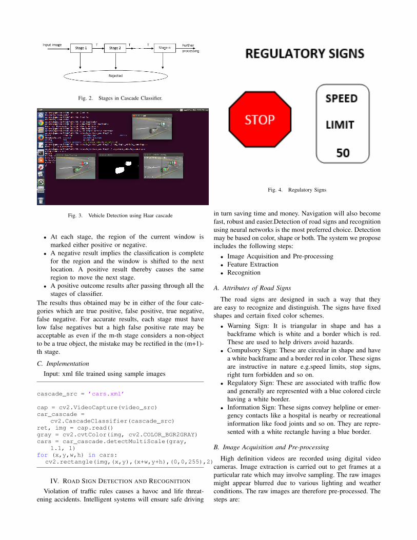
Fig. 2. Stages in Cascade Classifier.
Fig. 3. Vehicle Detection using Haar cascade
• At each stage, the region of the current window ismarked either positive or negative.
• A negative result implies the classification is completefor the region and the window is shifted to the nextlocation. A positive result thereby causes the sameregion to move the next stage.
• A positive outcome results after passing through all thestages of classifier.
The results thus obtained may be in either of the four cate-gories which are true positive, false positive, true negative,false negative. For accurate results, each stage must havelow false negatives but a high false positive rate may beacceptable as even if the m-th stage considers a non-objectto be a true object, the mistake may be rectified in the (m+1)-th stage.
C. Implementation
Input: xml file trained using sample images
cascade_src = ’cars.xml’
cap = cv2.VideoCapture(video_src)car_cascade =
cv2.CascadeClassifier(cascade_src)ret, img = cap.read()gray = cv2.cvtColor(img, cv2.COLOR_BGR2GRAY)cars = car_cascade.detectMultiScale(gray,
1.1, 1)for (x,y,w,h) in cars:
cv2.rectangle(img,(x,y),(x+w,y+h),(0,0,255),2)
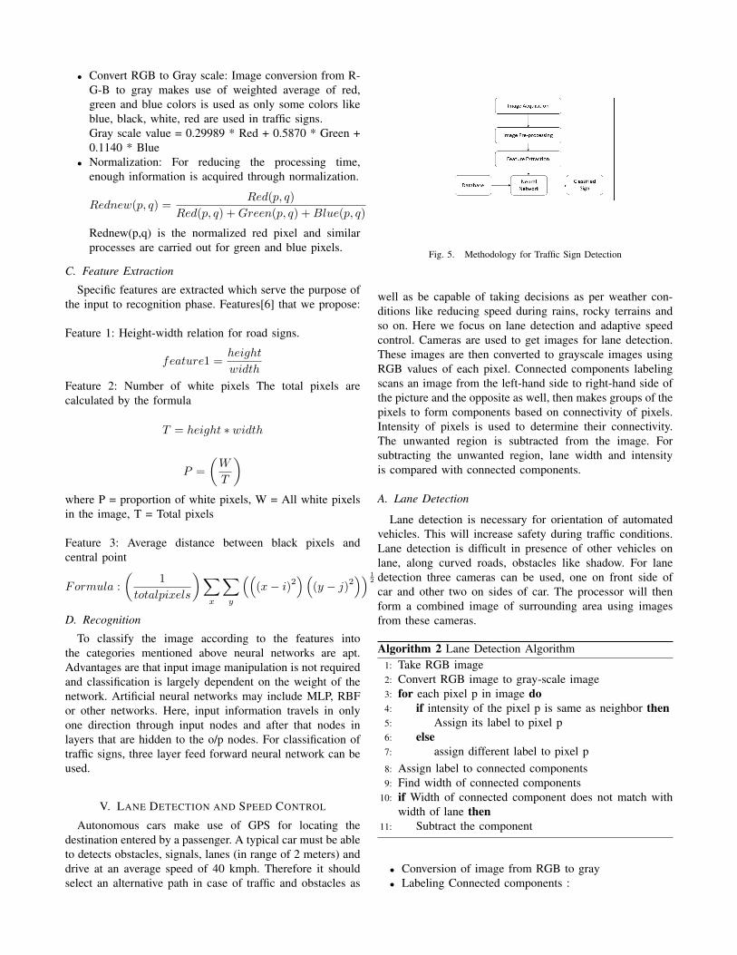
IV. ROAD SIGN DETECTION AND RECOGNITION
Violation of traffic rules causes a havoc and life threat-ening accidents. Intelligent systems will ensure safe driving
Fig. 4. Regulatory Signs
in turn saving time and money. Navigation will also becomefast, robust and easier.Detection of road signs and recognitionusing neural networks is the most preferred choice. Detectionmay be based on color, shape or both. The system we proposeincludes the following steps:
• Image Acquisition and Pre-processing• Feature Extraction• Recognition
A. Attributes of Road Signs
The road signs are designed in such a way that theyare easy to recognize and distinguish. The signs have fixedshapes and certain fixed color schemes.
• Warning Sign: It is triangular in shape and has abackframe which is white and a border which is red.These are used to help drivers avoid hazards.
• Compulsory Sign: These are circular in shape and havea white backframe and a border red in color. These signsare instructive in nature e.g.speed limits, stop signs,right turn forbidden and so on.
• Regulatory Sign: These are associated with traffic flowand generally are represented with a blue colored circlehaving a white border.
• Information Sign: These signs convey helpline or emer-gency contacts like a hospital is nearby or recreationalinformation like food joints and so on. They are repre-sented with a white rectangle having a blue border.
B. Image Acquisition and Pre-processing
High definition videos are recorded using digital videocameras. Image extraction is carried out to get frames at aparticular rate which may involve sampling. The raw imagesmight appear blurred due to various lighting and weatherconditions. The raw images are therefore pre-processed. Thesteps are:
• Convert RGB to Gray scale: Image conversion from R-G-B to gray makes use of weighted average of red,green and blue colors is used as only some colors likeblue, black, white, red are used in traffic signs.Gray scale value = 0.29989 * Red + 0.5870 * Green +0.1140 * Blue
• Normalization: For reducing the processing time,enough information is acquired through normalization.
Rednew(p, q) =Red(p, q)
Red(p, q) +Green(p, q) +Blue(p, q)
Rednew(p,q) is the normalized red pixel and similarprocesses are carried out for green and blue pixels.
C. Feature Extraction
Specific features are extracted which serve the purpose ofthe input to recognition phase. Features[6] that we propose:
Feature 1: Height-width relation for road signs.
feature1 =height
width
Feature 2: Number of white pixels The total pixels arecalculated by the formula
T = height ∗ width
P =
(W
T
)where P = proportion of white pixels, W = All white pixelsin the image, T = Total pixels
Feature 3: Average distance between black pixels andcentral point
Formula :
(1
totalpixels
)∑x
∑y
(((x− i)
2)(
(y − j)2)) 1
2
D. Recognition
To classify the image according to the features intothe categories mentioned above neural networks are apt.Advantages are that input image manipulation is not requiredand classification is largely dependent on the weight of thenetwork. Artificial neural networks may include MLP, RBFor other networks. Here, input information travels in onlyone direction through input nodes and after that nodes inlayers that are hidden to the o/p nodes. For classification oftraffic signs, three layer feed forward neural network can beused.
V. LANE DETECTION AND SPEED CONTROL
Autonomous cars make use of GPS for locating thedestination entered by a passenger. A typical car must be ableto detects obstacles, signals, lanes (in range of 2 meters) anddrive at an average speed of 40 kmph. Therefore it shouldselect an alternative path in case of traffic and obstacles as
Fig. 5. Methodology for Traffic Sign Detection
well as be capable of taking decisions as per weather con-ditions like reducing speed during rains, rocky terrains andso on. Here we focus on lane detection and adaptive speedcontrol. Cameras are used to get images for lane detection.These images are then converted to grayscale images usingRGB values of each pixel. Connected components labelingscans an image from the left-hand side to right-hand side ofthe picture and the opposite as well, then makes groups of thepixels to form components based on connectivity of pixels.Intensity of pixels is used to determine their connectivity.The unwanted region is subtracted from the image. Forsubtracting the unwanted region, lane width and intensityis compared with connected components.
A. Lane Detection
Lane detection is necessary for orientation of automatedvehicles. This will increase safety during traffic conditions.Lane detection is difficult in presence of other vehicles onlane, along curved roads, obstacles like shadow. For lanedetection three cameras can be used, one on front side ofcar and other two on sides of car. The processor will thenform a combined image of surrounding area using imagesfrom these cameras.
Algorithm 2 Lane Detection Algorithm1: Take RGB image2: Convert RGB image to gray-scale image3: for each pixel p in image do4: if intensity of the pixel p is same as neighbor then5: Assign its label to pixel p6: else7: assign different label to pixel p8: Assign label to connected components9: Find width of connected components
10: if Width of connected component does not match withwidth of lane then
11: Subtract the component
• Conversion of image from RGB to gray• Labeling Connected components :
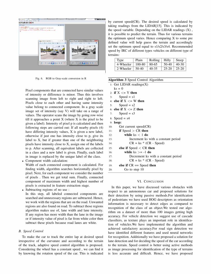
Fig. 6. RGB to Gray-scale conversion in R
Pixel components that are connected have similar valuesof intensity or difference is minor. Thus this involvesscanning image from left to right and right to left.Pixels close to each other and having same intensityvalue belong to connected component. In a gray scaleimage set of intensity (say V) will take on a range ofvalues. The operator scans the image by going row-wisetill it approaches a point X (where X is the pixel to begiven a label). Intensity of pixel p is calculated and thenfollowing steps are carried out: If all nearby pixels (4)have differing intensity values, X is given a new label,otherwise if just one has intensity close to p, give itslabel to X, but if greater than one of the neighboringpixels have intensity close to X, assign one of the labelsto p. After scanning, all equivalent labels are collectedin a class and a new label is given. Finally, each labelin image is replaced by the unique label of the class.
• Component width calculation:Width of each connected component is calculated. Forfinding width, algorithm searches horizontally pixel bypixel. Next, for each component we consider the numberof pixels . Then we get total sum. Finally, connectedcomponent of maximum width and highest number ofpixels is extracted in feature extraction stage.
• Subtracting regions of no use :In this step, all labeled connected components aresearched and unnecessary regions are subtracted. Hence,we work with the regions that are on the road. Unwantedregions are also found on road. To subtract those regionsalgorithm makes use of, lane width and lane intensity.If any region has more width than the lane in the imageor if intensity value of pixel is far from white color thensubtract these pixels because road lanes are white.
B. Speed Control
To make the car to track the entire lap at desired speedirrespective of the curvature and according to the terrainof the track, adaptive speed control algorithm is proposed.Considering the wheel has a constant speed , we can find itby knowing the rotation speed of the car. This is indicated
by current speed(CR). The desired speed is calculated bytaking readings from the LIDAR[15]. This is indicated bythe speed variable. Depending on the LIDAR readings (X) ,it is possible to predict the terrain. Thus for various terrainsthe optimum speed varies. Hence comparing X to some predefined value will help guess the terrain and accordinglyset the optimum speed equal to s1/s2/s3/s4. Recommendedspeed by IRC of different types vehicles on different type ofterrains:
Type Plain Rolling Hilly Steep4-Wheeler 100-80 80-65 50-40 40-302-Wheeler 50-40 40-35 25-20 25-20
Algorithm 3 Speed Control Algorithm1: Get LIDAR readings(X)
ks = 02: if X <= Y then3: Speed = s14: else if X <= W then5: Speed = s26: else if X <= Z then7: Speed = s38: Speed = s49: loop:
10: Get current speed(CR)11: if Speed > CR then12: while ks < 1 do13: Increment ks with a constant period14: CR = ks * (CR - Speed)15: else if Speed < CR then16: while ks >= -1 do17: Decrement ks with a constant period18: CR = ks * (CR - Speed)19: else if CR == Speed then20: Go to step 10
VI. CONCLUSION
In this paper, we have discussed various obstacles withrespect to an autonomous car and proposed solutions fortheir detection by using passive methods.For identificationof pedestrians we have used HOG descriptors as orientationinformation is necessary to detect edges as compared torecognition of the class of an object.We tested our algo-rithm on a dataset of more than 100 images getting highaccuracy. For vehicle detection we suggest use of cascadeclassifiers, as texture plays an important role in identifica-tion of vehicles.We have implemented the algorithm andachieved satisfactory accuracy.For road sign detection wehave identified different features and used neural networksfor recognition. Additionally we have proposed a solution forlane detection and for deciding the speed of the car accordingto the terrain. Speed control is better using active methodsas image processing for identification of the type of terrainsis less accurate and difficult. Hence, we have proposed
a simple algorithm using LIDAR readings. We propoundlane detection using passive methods. It is a straightforwardalgorithm and has less time complexity as only a change inthe intensity of pixels in grayscale images is used to detectlanes.
REFERENCES
[1] A Pedestrian Detector Using Histograms of Oriented Gradients and aSupport Vector Machine Classifier. M. Bertozzi ; A. Broggi ; M. DelRose ; M. Felisa ; A. Rakotomamonjy ; F. Suard. ITSC 2007. IEEE
[2] Traffic Sign Classification based on Neural Network for AdvanceDriver Assistance System, Aini HUSSAIN, Mahammad A. HANNAN,Tan J. PIN, Salina A. SAMAD, Safat B. WALI, Department of Elec-trical, Electronic and Systems Engineering, University KebangsaanMalaysia,2015
[3] Machine Learning For Object Recognition and Scene Analysis, S.Moscatelli and Y. Kodratoff, 1994
[4] Object Recognition as Machine Translation-I: Learning a Lexicon for aFixed Image Vocabulary K. Barnard, J.F.G.deFreitas,P. Duygulu, D.A.Forsyth Computer Science Division, U.C. Berkeley, CA Department ofComputer Science, University of British Columbia, Vancouver, 2002
[5] Learning Methods for Generic Object Recognition with Invariance toPose and Lighting, Leon Bottou NEC Labs America, Princeton, FuJie Huang, Yann LeCun, 2004
[6] A Real Time Road Sign Recognition using Neural Network Moham-mad Badrul Alam Miah Dept. of Information and CommunicationTechnology Mawlana Bhashani Science and Technology UniversitySantosh, Tangail-1902, Bangladesh
[7] Betke, Margrit, Esin Haritaoglu, and Larry S. Davis. ”Real-time mul-tiple vehicle detection and tracking from a moving vehicle.” Machinevision and applications 12.2 (2000): 69-83.
[8] Rapid object detection using a boosted cascade of simple features, P.Viola, M. Jones, 2001
[9] Lienhart, Rainer, and Jochen Maydt. ”An extended set of haar-like features for rapid object detection.” Image Processing. 2002.Proceedings. 2002 International Conference on. Vol. 1. IEEE, 2002.
[10] Gavrila, Dariu M., and Vasanth Philomin. ”Real-time object detectionfor” smart” vehicles.” Computer Vision, 1999. The Proceedings of theSeventh IEEE International Conference on. Vol. 1. IEEE, 1999.
[11] Andreasson, Henrik, Andr Treptow, and Tom Duckett. ”Self-localization in non-stationary environments using omni-directionalvision.” Robotics and Autonomous Systems 55.7 (2007): 541-551.
[12] Sun, Zehang, et al. ”A real-time precrash vehicle detection system.”Applications of Computer Vision, 2002.(WACV 2002). Proceedings.Sixth IEEE Workshop on. IEEE, 2002.
[13] Han, Feng, et al. ”A two-stage approach to people and vehicledetection with hog-based svm.” Performance Metrics for IntelligentSystems 2006 Workshop. 2006.
[14] Varghese, Jaycil Z., and Randy G. Boone. ”Overview of AutonomousVehicle Sensors and Systems.” Tech. rep. Proceedings of the 2015International Conference on Operations Excellence and Service Engi-neering Orlando, Florida, USA, 2015.
[15] http://www.pyimagesearch.com/2015/11/09/pedestrian-detection-opencv/
[16] http://pascal.inrialpes.fr/data/human/[17] http://www.cs.utexas.edu/ grauman/courses/spring2008/datasets.htm[18] http://vision.stanford.edu/Datasets/40actions.html[19] Convergence and Hybrid Information Technology: 5th International
Conference, ICHIT 2011, Daejeon, Korea, September 22-24, 2011