Embed Size (px)
Citation preview
Machine Guarding Safety Plan
2019
INJURY ILLNESS PREVENTION PROGRAM
CAL MARITIME| 200 Maritime Academy Vallejo, CA 94590

Machine Guarding Safety Plan
Electronically Controlled. Latest revision is in the Document Management System. A printed copy is uncontrolled and may be outdated unless it bears a red ink “controlled copy” stamp.
Cal Maritime Department of Safety & Risk Management
Injury Illness Prevention Program Document # 09-04020 Revision: 002 Page 1 of 39
This sheet should be completed each time the Machine Guarding Safety Program is reviewed and/or modified. The Director of Safety and Risk Management is responsible for the review and update this document annually or more frequently as determined or needed per CSU Chancellor’s Executive Order 1039 Occupational Health and Safety Policy, 1069 Risk Management as well as Cal Maritime A&F Policy 09-004 IIPP.
Version Date Approved Author Revision Notes:
1.0 04/01/2018 Marianne Spotorno, CSP
Dir. Safety & Risk Management New Program Document
2.0 08/01/2019 Marianne Spotorno, CSP Dir. Safety & Risk Management
• Campus Emergency Response update. • TSGB component update
Machine Guarding Safety Plan
Electronically Controlled. Latest revision is in the Document Management System. A printed copy is uncontrolled and may be outdated unless it bears a red ink “controlled copy” stamp.
Cal Maritime Department of Safety & Risk Management
Injury Illness Prevention Program Document # 09-04020 Revision: 002 Page 2 of 39
Table of Contents
1.0 Purpose & Scope ...................................................................................................................................... 5 1.1 Regulatory Standards Reference .......................................................................................................................................................... 5
1.2 CSU-System & Cal Maritime Specific Reference................................................................................................................................... 6
1.3 Other Resources .................................................................................................................................................................................... 6
2.0 Administrative Duties & Responsibilities ............................................................................................ 6 2.1 Employees (Including Student workers) ......................................................................................................................................... 6
2.2 Department of Safety and Risk Management (SRM) ..................................................................................................................... 6
2.3 Deans, Directors, Department or Operating Unit Management .................................................................................................... 7
2.4 Supervisors and Principal Investigators .......................................................................................................................................... 7
2.5 Academic Programming Faculty and Advisors ............................................................................................................................... 7
2.6 Students- Cadets ............................................................................................................................................................................ 8
2.7 Machine Users ................................................................................................................................................................................ 8
2.8 Owner Department ........................................................................................................................................................................ 8
3.0 Process Management ............................................................................................................................... 9
3.1 Hazard Identification, Risk Assessment & Control (HIRAC) ........................................................................ 9 3.1.1 Integrated Safety Management (ISM) ............................................................................................................................................... 9
3.1.2 Hazard Identification, Risk Assessment &Determining Control Table (HIRAC)................................................................................ 9
3.1.3 Application of Hierarchy of Controls ................................................................................................................................................. 9
3.1.4 Job Hazards Analysis (JHA)............................................................................................................................................................... 10
3.1.4.1 JHA Requirements ..................................................................................................................................................................... 10
3.2 Hazard Assessment ............................................................................................................................................................................. 11
3.2.1 Hazard Assessment ...................................................................................................................................................................... 12
3.2.2 Hazardous Actions........................................................................................................................................................................ 12
3.2.3 Cutting. ......................................................................................................................................................................................... 12
3.2.4 Punching. ...................................................................................................................................................................................... 12
3.2.5 Bending. ........................................................................................................................................................................................ 12
3.2.6 Shearing. ....................................................................................................................................................................................... 12
3.2.7 Other Machine Hazards ............................................................................................................................................................... 12
3.3 General Machine Guarding Safety Requirements .............................................................................................................................. 13
3.3.1 Administrative Procedures ............................................................................................................................................................ 13
3.4 Machine Guards, Safe Guarding and Interlocks Overview ................................................................................................................. 13
3.4.1 Machine Guarding Requirements for All Machines ....................................................................................................................... 13
3.4.2 Hazardous Parts, Motions and Actions .......................................................................................................................................... 13
Machine Guarding Safety Plan
Electronically Controlled. Latest revision is in the Document Management System. A printed copy is uncontrolled and may be outdated unless it bears a red ink “controlled copy” stamp.
Cal Maritime Department of Safety & Risk Management
Injury Illness Prevention Program Document # 09-04020 Revision: 002 Page 3 of 39
3.4.3 Point of Operation ........................................................................................................................................................................ 14
3.5 Machine Guards ................................................................................................................................................................................... 15
3.5.1 Fixed Guards ................................................................................................................................................................................. 15
3.5.2 Interlocked Guards and Latch Control Circuits ............................................................................................................................. 15
3.5.3 Adjustable Guards ......................................................................................................................................................................... 15
3.5.4 Self-adjusting Guards .................................................................................................................................................................... 15
3.6 Machine Guard Construction .............................................................................................................................................................. 16
3.6.1 Manufactured versus Aftermarket / Retrofit Guards ................................................................................................................... 16
3.7 Safeguarding Devices .......................................................................................................................................................................... 17
3.7.1 Barriers and Gates ........................................................................................................................................................................ 17
3.7.2 Presence-Sensing Devices ............................................................................................................................................................. 17
3.7.3 Pressure-sensitive Devices ............................................................................................................................................................ 17
3.7.4 Pullbacks and Restraints ................................................................................................................................................................ 17
3.8 Physical Restraint Device .................................................................................................................................................................... 17
3.8.1 Two-hand Control and Trip Devices .............................................................................................................................................. 17
3.9 Machine Safeguarding and Risk Reduction Methods .......................................................................................................................... 18
3.9.1 Access to Machinery ..................................................................................................................................................................... 18
3.9.2 Anchoring Fixed Machinery .......................................................................................................................................................... 18
3.9.3 Awareness Barriers and Signals .................................................................................................................................................... 18
3.9.4 Controls ......................................................................................................................................................................................... 18
3.10 Various styles of machine start/stop controls ................................................................................................................................. 19
3.10.1 Emergency Stop Devices ............................................................................................................................................................. 19
3.10.2 Energy Isolation – Lockout Tagout (LOTO) .................................................................................................................................. 19
3.10.3 Energy Source / Utility Interruption ............................................................................................................................................ 19
3.10.4 Fail-Safe Design ........................................................................................................................................................................... 20
3.10.5 Feeding and Ejection Methods ................................................................................................................................................... 20
3.11 Various hand feeding and retrieval tools ......................................................................................................................................... 20
3.11.1 Hand-Feeding and Retrieval Tools .............................................................................................................................................. 20
3.11.2 Location / Distance ..................................................................................................................................................................... 20
3.11.3 Shields ......................................................................................................................................................................................... 20
3.12 Signs, Labels and Color Coding ......................................................................................................................................................... 20
3.13 Machine Operator Procedures ......................................................................................................................................................... 21
3.13.1 Users of Machines with Safe-Guards ........................................................................................................................................... 21
3.14 Safeguarding Assessment .................................................................................................................................................................. 21
4.0 Training Requirements ............................................................................................................................ 23 4.1 Personnel Operating Machines............................................................................................................................................................ 23
Machine Guarding Safety Plan
Electronically Controlled. Latest revision is in the Document Management System. A printed copy is uncontrolled and may be outdated unless it bears a red ink “controlled copy” stamp.
Cal Maritime Department of Safety & Risk Management
Injury Illness Prevention Program Document # 09-04020 Revision: 002 Page 4 of 39
4.2 Retraining should be provided whenever ............................................................................................................................................ 23
4.3 Managers, Supervisors, PIs, “Equipment Owner” ............................................................................................................................... 23
4.4 Maintenance and Service Personnel ................................................................................................................................................... 24
5.0 Document Control & Recordkeeping ....................................................................................................... 25
Appendix A: Definitions ................................................................................................................................ 26
Appendix B: Job Hazard Analysis Template Sample ....................................................................................... 28
Appendix C: Job Hazard Analysis: Bench Grinder ........................................................................................... 30 BENCH GRINDER ........................................................................................................................................................................................ 30
Appendix D: Inspecting of Equipment .......................................................................................................... 31
Appendix E: Machine Guarding Assessment Checklist ................................................................................... 32
Appendix F: Machine-Specific Examples of Guards ........................................................................................ 33
Appendix G: Equipment Inventory ................................................................................................................ 34
Appendix H: Job Hazard Analysis Library ....................................................................................................... 35
Appendix I: Emergency Response ................................................................................................................. 36
Appendix J: Accident Incident Management ................................................................................................. 37
Machine Guarding Safety Plan
Electronically Controlled. Latest revision is in the Document Management System. A printed copy is uncontrolled and may be outdated unless it bears a red ink “controlled copy” stamp.
Cal Maritime Department of Safety & Risk Management
Injury Illness Prevention Program Document # 09-04020 Revision: 002 Page 5 of 39
1.0 Purpose & Scope The purpose of the Injury Illness Prevention Program (IIPP) is to outline Cal Maritime’s environmental health and safety requirements, expectations, and responsibilities in order to achieve effective campus safety performance through Integrated Safety Management (ISM). The Machine Guarding Safety Program is a subject specific component the supports the overall University IIPP. This Manual applies to all Cal Maritime operations, maintenance and construction activities under the supervision of Cal Maritime personnel. For activities associated with the Training Ship Golden Bear (TSGB) refer to the Vessel Operating Manual (VOM) and/or Shoreside Administrative Manual (SAM). The TSGB is a subject specific component that supports the overall University IIPP.
1.1 Regulatory Standards Reference Cal Maritime and its subcontractors shall comply with the following requirements. In case of conflict or overlap of the below references, the most stringent provision shall apply.
• Occupational Safety and Health Act (OSHA), 1904, 1910, 1915,1917,1918,1926 • California Code of Regulations (CCR), Title 8, GISO, CSO, ESO Fed/OSHA Regulations • Maritime PART 1917 - Marine Terminals • General Industry (29 CFR 1910) • 1910 Subpart O, Machinery and machine guarding. Includes definitions, general requirements, and different kinds
of machinery requirements. o 1910.211, Definitions o 1910.212, General requirements for all machines o 1910.213, Woodworking machinery requirements o 1910.214, Cooperage machinery [Reserved] o 1910.215, Abrasive wheel machinery o 1910.216, Mills and calendars in the rubber and plastics industries o 1910.217, Mechanical power presses. Includes general requirements in addition to specific requirements
for construction, safeguarding, dies, inspection, maintenance, modification, operation, injury reporting, and presence sensing device initiation (PSDI). Appendix A, Mandatory requirements for certification/validation of safety systems for presence
sensing device initiation of mechanical power presses Appendix B, Non-mandatory guidelines for certification/validation of safety systems for presence
sensing device initiation of mechanical power presses Appendix C, Mandatory requirements for OSHA recognition of third-party validation organizations
for the PSDI standard Appendix D, Non-mandatory supplementary information
o 1910.218, Forging machines o 1910.219, Mechanical power-transmission apparatus
• 1910 Subpart R, Special industries o 1910.262, Textiles. Paragraph (c)(3) [reserved] contains a short statement on machine guarding
requirements and a reference to 29 CFR 1910.219. [related topic page] o 1910.263, Bakery equipment. Paragraph (c) addresses general requirements for machine guarding. o 1910.268, Telecommunications. Paragraph (b)(1)(v) addresses some general requirements for machine
guarding
Machine Guarding Safety Plan
Electronically Controlled. Latest revision is in the Document Management System. A printed copy is uncontrolled and may be outdated unless it bears a red ink “controlled copy” stamp.
Cal Maritime Department of Safety & Risk Management
Injury Illness Prevention Program Document # 09-04020 Revision: 002 Page 6 of 39
1.2 CSU-System & Cal Maritime Specific Reference For additional information on Cal Maritime environmental health and safety policies, refer to:
• CSU Executive Order 1039, 1056, 1069 • Cal Maritime Policy AF 09-003, AF 09-004
1.3 Other Resources • University of California, Berkeley—Machine Guarding and Equipment Safety Program
2.0 Administrative Duties & Responsibilities It is the policy of the Cal Maritime to maintain a safe and healthy work environment for each employee (including student and contract employees), and to comply with all applicable occupational health and safety regulations. This Injury and Illness Prevention Program (IIPP) is intended to establish a framework for identifying and correcting workplace hazards within the department, while addressing legal requirements for a formal, written IIPP. To assist Cal Maritime in providing a safe, compliant, environmentally sound, and more sustainable operation, each department or operational unit is expected to review, understand, and follow the guidance provided in the Injury Illness Prevention Program components and the and the function of the integrated campus safety management system (ICSMS) as related to operations under their control. In a proactive behavior based environmental health and safety model that entire campus community participation reflects a process that embraces the ability to;
• Eliminate adverse conditions which may result in injury or illness, • Recommend the establishment of programs to raise safety consciousness in the community, and • Achieve and maintain a beneficial relationship through continuing communication on issues relating to
environmental health and occupational safety.
2.1 Employees (Including Student workers) It is the responsibility of all faculty and staff to proactively participate and subsequently comply with all applicable health and safety regulations, Cal Maritime policies, and established safe work practices. This includes, but is not limited to:
• Observing health and safety-related signs, posters, warning signals and directions. • Learning about the potential hazards of assigned tasks and work areas. • Taking part in appropriate health and safety training. • Following all safe operating procedures and precautions. • Participating in workplace safety inspections • Using proper personal protective equipment. • Inform coworkers and supervisors of defective equipment and other workplace hazards without fear of reprisal. • Reviewing the building emergency plan and assembly area. • Reporting unsafe conditions immediately to a supervisor, and stopping work if an imminent hazard is presented.
2.2 Department of Safety and Risk Management (SRM) The Director of Safety and Risk Management (SRM), as delegated by the University President, is responsible for the implementation and administrative management for Cal Maritime’s Injury Illness Prevention Program (IIPP) that meets the requirements of California Code of Regulations (CCR), Title 8, section 3203) as well as other applicable California and Federal Occupational Safety and Health (Cal-OSHA) requirements. Further responsibilities are outlined below:
• Provide advice and guidance to all university personnel concerning IIPP compliance requirements;
Machine Guarding Safety Plan
Electronically Controlled. Latest revision is in the Document Management System. A printed copy is uncontrolled and may be outdated unless it bears a red ink “controlled copy” stamp.
Cal Maritime Department of Safety & Risk Management
Injury Illness Prevention Program Document # 09-04020 Revision: 002 Page 7 of 39
• Provide centralized monitoring of campus activities related to implementation of campus IIPP; • Ensure scheduled periodic safety inspections are performed in compliance with regulatory requirements and assist
management staff in identifying unsafe or unhealthful conditions; • Ensure safety and health training programs comply with regulatory requirements and university policy; • Oversee the maintenance of safety and health records consistent with the requirements of this document and
regulatory mandates; • Ensure program audits, both scheduled and as required by a process, equipment or personnel change, or by a safety
program mandate, are performed; • Interpret existing or pending safety and health legislation and recommend appropriate compliance strategies to
university personnel; • Maintain centralized environmental and employee monitoring records, allowing employee access as directed by law. • Conduct at least an annual review of this document and make the current revision available on the SRM web site.
2.3 Deans, Directors, Department or Operating Unit Management Campus Department or Operating Unit Head leadership have an integral campus role and shall have a thorough understanding of Injury Illness Prevention Program components and the function of the integrated campus safety management system (ICSMS) as related to operations under their control.
• The Department Head has primary authority and responsibility to ensure the health and safety of the department's faculty, staff and students through the implementation of the Injury Illness Prevention Program components. This is accomplished by communicating the Cal Maritime’s campus emphasis on health and safety, analyzing work procedures for hazard identification and correction, ensuring regular workplace inspections, providing health and safety training, and encouraging prompt employee reporting of health and safety concerns without fear of reprisal.
• Specific areas include employee and student (both student employees and students in academic programs) education and training, identification and correction of unsafe conditions, and record keeping. It is recognized that a substantial amount of responsibility falls at this level.
• Colleges and Departments are encouraged to designate an individual as the College or department safety coordinator, to assist with specific operational environmental health and safety process management components.
2.4 Supervisors and Principal Investigators Supervisors play a key role in the implementation of the Cal Maritime’s Injury Illness Prevention Program components. Supervisors may be Management, Senior Research Associates, Department Chairs, Principal Investigators, or others who oversee a project and/or staff. They are responsible for but not limited to:
• Communicating to their staff and students about Cal Maritime campus's emphasis on health and safety. • Ensuring periodic, documented inspection of workspaces under their authority. • Promptly correcting identified hazards. • Modeling and enforcing safe and healthful work practices. • Providing appropriate safety training and personal protective equipment. • Implementing measures to eliminate or control workplace hazards. • Stopping any employee’s work that poses an imminent hazard to either the employee or any other individual. • Encouraging employees to report health and safety issues without fear of reprisal.
2.5 Academic Programming Faculty and Advisors It is the responsibility of Faculty, Academic Programming Advisors other Cal Maritime related activities and student clubs to:
• Develop procedures to ensure effective compliance and support of the Injury and Illness Prevention Program components as it relates to operations under their control. Specific areas of responsibility include student education and training, identification and correction of unsafe conditions, and incident reporting.
• Develop and maintain written classroom, laboratory, and activity procedures which conform to regulatory, campus and departmental guidelines.
Machine Guarding Safety Plan
Electronically Controlled. Latest revision is in the Document Management System. A printed copy is uncontrolled and may be outdated unless it bears a red ink “controlled copy” stamp.
Cal Maritime Department of Safety & Risk Management
Injury Illness Prevention Program Document # 09-04020 Revision: 002 Page 8 of 39
• Instruct students in the recognition, avoidance, and response to unsafe conditions, including hazards associated with non-routine tasks and emergency operations
• Permit only those persons qualified by education and training to operate potentially hazardous equipment or use hazardous materials, unless under close supervision.
• Supervise students in the performance of activities.
2.6 Students- Cadets Students are expected to always adhere to safety practices presented by faculty, technical staff, student assistants, graduate assistants or other authorized individuals. They must also report potentially hazardous conditions that become known to them. These reports should be made to their supervisors, faculty advisers, Department of Safety and Risk Management, or other responsible parties.
2.7 Machine Users
• Is trained on and applies “Safe-Work Rules” for users as outlined in this program. • Always selects and uses a hand and power tools in a safe manner. • Visual inspect prior to use. • Alerts Owner Department Management when hand and/or power tools need repair/replacement. • Assesses work to determine if fall protection should be worn and seeks alternative access methods instead of hand
and/or power tools if need be. • Proactively use Stop Work Authority when they feel there is an unsafe condition present by means of communicating
with Department Management and SRM to work collaboratively to resolve and improve identified or perceived condition.
Users of a machine / equipment that is old, proprietary or designed “in-house” and was not designed / built / installed with appropriate guards must:
• Bring to management’s attention when an unguarded machine location should be guarded • Develop a plan to work away from the unguarded location or otherwise limit access to the unguarded location while
using the machine • Work with SRM to develop safe-work protocols to include safety-interlocks on research and other equipment that
would enhance compliance and safe use / operation of the equipment for personnel • Work with SRM to develop a plan to retrofit “after-market” guards and/or interlocks on equipment as work-
demands, budget and time constraints require for compliance 2.8 Owner Department
• The “Owner Department” is responsible to identify hazards/activities in their workplace and design into locations engineering controls such as guards, barriers, edge protection, etc., to prevent access to a hazard. Only when engineering controls cannot be used/implemented PPE may be used to aid in controlling hazards to personnel in a Department’s operations/facilities.
• The department owning or exposing personnel to hazards is responsible for the selection of the proper equipment based upon a hazard analysis of work tasks. In addition, Owner Departments must provide training to their personnel who use the equipment, keep the records of training completed, and schedule semi-annual inspections of all equipment under their ownership/control.
• Toward this end, the Department owning the equipment must: • Assign a Safety Program Coordinator to aid in operational program management for the Department. • Notify SRM when new equipment is purchased so that it can be inspected and added to the JHA and Equipment
inventory. • Schedule with SRM a semi-annual inspection.
Machine Guarding Safety Plan
Electronically Controlled. Latest revision is in the Document Management System. A printed copy is uncontrolled and may be outdated unless it bears a red ink “controlled copy” stamp.
Cal Maritime Department of Safety & Risk Management
Injury Illness Prevention Program Document # 09-04020 Revision: 002 Page 9 of 39
• Render unusable and then dispose of any equipment that is in any way questionably safe as determined by the inspector or the person using the equipment.
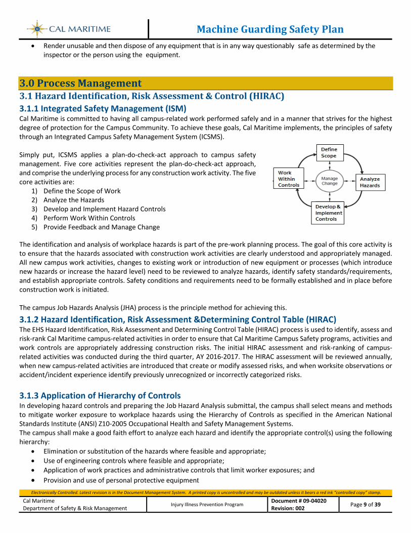
3.0 Process Management 3.1 Hazard Identification, Risk Assessment & Control (HIRAC) 3.1.1 Integrated Safety Management (ISM) Cal Maritime is committed to having all campus-related work performed safely and in a manner that strives for the highest degree of protection for the Campus Community. To achieve these goals, Cal Maritime implements, the principles of safety through an Integrated Campus Safety Management System (ICSMS). Simply put, ICSMS applies a plan-do-check-act approach to campus safety management. Five core activities represent the plan-do-check-act approach, and comprise the underlying process for any construction work activity. The five core activities are:
1) Define the Scope of Work 2) Analyze the Hazards 3) Develop and Implement Hazard Controls 4) Perform Work Within Controls 5) Provide Feedback and Manage Change
The identification and analysis of workplace hazards is part of the pre-work planning process. The goal of this core activity is to ensure that the hazards associated with construction work activities are clearly understood and appropriately managed. All new campus work activities, changes to existing work or introduction of new equipment or processes (which introduce new hazards or increase the hazard level) need to be reviewed to analyze hazards, identify safety standards/requirements, and establish appropriate controls. Safety conditions and requirements need to be formally established and in place before construction work is initiated. The campus Job Hazards Analysis (JHA) process is the principle method for achieving this.
3.1.2 Hazard Identification, Risk Assessment &Determining Control Table (HIRAC) The EHS Hazard Identification, Risk Assessment and Determining Control Table (HIRAC) process is used to identify, assess and risk-rank Cal Maritime campus-related activities in order to ensure that Cal Maritime Campus Safety programs, activities and work controls are appropriately addressing construction risks. The initial HIRAC assessment and risk-ranking of campus-related activities was conducted during the third quarter, AY 2016-2017. The HIRAC assessment will be reviewed annually, when new campus-related activities are introduced that create or modify assessed risks, and when worksite observations or accident/incident experience identify previously unrecognized or incorrectly categorized risks.
3.1.3 Application of Hierarchy of Controls In developing hazard controls and preparing the Job Hazard Analysis submittal, the campus shall select means and methods to mitigate worker exposure to workplace hazards using the Hierarchy of Controls as specified in the American National Standards Institute (ANSI) Z10-2005 Occupational Health and Safety Management Systems. The campus shall make a good faith effort to analyze each hazard and identify the appropriate control(s) using the following hierarchy:
• Elimination or substitution of the hazards where feasible and appropriate; • Use of engineering controls where feasible and appropriate; • Application of work practices and administrative controls that limit worker exposures; and • Provision and use of personal protective equipment
Machine Guarding Safety Plan
Electronically Controlled. Latest revision is in the Document Management System. A printed copy is uncontrolled and may be outdated unless it bears a red ink “controlled copy” stamp.
Cal Maritime Department of Safety & Risk Management
Injury Illness Prevention Program Document # 09-04020 Revision: 002 Page 10 of 39
3.1.4 Job Hazards Analysis (JHA) For the purposes of this section Job Hazard Analysis (JHA) and Job Safety Analysis (JSA) can be used synonymously. A JHA/JSA can be incorporated into a Pre Task Plan, provided there is a section for employees to review, comment and sign. Core components of the scope of work and relative hazards can be electronically completed ahead of time, provided there is room for current site conditions are able to be readily added as applicable. When the scope or conditions change, the change in work plan should be noted in a different colored pen with employee’s initially that they have been briefed on the change. The Department of Safety and Risk Management will work with individual Departments to develop a master Campus JHA library.
• Each employee scheduled to work in the activities identified below shall receive safety training in those activities prior to working on them.
• Subcontractors shall submit a Job Hazards Analysis (JHA) for those construction activities meeting the requirements for performing JHA (see below). The JHA shall be reviewed and authorized to proceed by the Cal Maritime Department of Safety and Risk Management before work commences.
• Subcontractor shall be responsible for submitting a JHA and work procedures to Cal Maritime Department of Safety and Risk Management for review a minimum of seven days prior to the start of work for most work activities.
3.1.4.1 JHA Requirements A JHA shall be written based on the following conditions:
• Jobs with the highest injury or illness rates • Jobs with the potential to cause severe or disabling injuries or illness, even if there is no history of previous accidents • Jobs in which one simple human error could lead to a severe accident or injury • Jobs that are new to your operation or have undergone changes in processes and procedures • Jobs complex enough to require written instructions.
If not otherwise specified in a particular project specification, the JHA shall be performed in accordance with the OSHA 3071. JHA processes. In general the JHA will include:
• Description of work phase or activity • Identification of potential hazards associated with the activity • Address further hazards revealed by supplemental site information (e.g., site characterization data, as-built drawings)
provided by the subcontractors construction manager. • A list of the Subcontractor’s planned controls to mitigate the identified hazards • Identification of specialized training required • Identification of special permits required • Name of the Subcontractor’s Competent Person(s) responsible for inspecting the activity and ensuring that all
proposed safety measures are followed.
Machine Guarding Safety Plan
Electronically Controlled. Latest revision is in the Document Management System. A printed copy is uncontrolled and may be outdated unless it bears a red ink “controlled copy” stamp.
Cal Maritime Department of Safety & Risk Management
Injury Illness Prevention Program Document # 09-04020 Revision: 002 Page 11 of 39
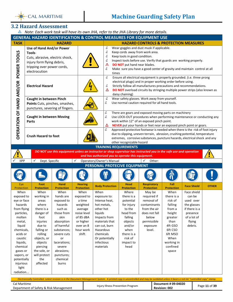
3.2 Hazard Assessment Note: Each work task will have its own JHA, refer to the JHA Library for more details.
GENERAL HAZARD IDENTIFICATION & CONTROL MEASURES FOR EQUIPMENT USE TASK HAZARD HAZARD CONTROLS & PROTECTION MEASURES
OPE
RATI
ON
OF
HAN
D AN
D/O
R P
OW
ER T
OO
LS Use of Hand And/or Power
Tools- Cuts, abrasive, electric shock, injury form flying debris, tripping over power cords, electrocution
Wear goggles and dust musk if applicable. Keep cords away from work area. Keep tools in good condition. Inspect tools before use. Verify that guards are working properly. DO NOT put hand near blades.
Make sure you have a good center of gravity and maintain control at all times
Electrical Hazard
Ensure all electrical equipment is properly grounded. (i.e. three prong electrical plugs) and in proper working order before using.
Strictly follow all manufactures precautions and recommendations. DO NOT overload circuits by stringing multiple power strips (also known as
daisy chaining) Caught in between Pinch Points Cuts, pinches, smashes, punctures, severing of fingers.
Wear safety glasses. Work away from yourself. Use normal caution required for all hand tools.
Caught in between Moving Parts
There are gears and exposed moving parts on machinery Use LOCK-OUT procedures when performing maintenance or conducting any
work within 12” of an exposed pinch point. NEVER put your hands or feet near an exposed pinch point or gears.
Crush Hazard to foot
Approved protective footwear is needed when there is the risk of foot injury due to slipping, uneven terrain, abrasion, crushing potential, temperature extremes, corrosive substances, puncture hazards, electrical shock and any other recognizable hazard
TRAINING REQUIREMENTS
DO NOT use this equipment unless an instructor or shop supervisor has instructed you in the safe use and operation
and has authorized you to operate this equipment. IIPP Dept. Specific Operators/Owner’s Manual Other:
PERSONAL PROTECIVE EQUIPMENT
Eye
Protection Foot
Protection Hand
Protection Hearing
Protection Body Protection Head Protection
Respiratory Protection
Fall Protection Face Shield OTHER
When exposed to eye or face
hazards from flying particles, molten metal, liquid
chemicals, acids or caustic liquids,
chemical gases or
vapors, or potentially injurious
light radiation...
When working in
areas where
there is a danger of
foot injuries due to
falling or rolling
objects, or objects piercing
the sole, or will protect
the affected
When hands are
exposed to hazards such as
those from skin
absorption of harmful
substances; severe cuts
or lacerations;
severe abrasions; punctures; chemical
burns
When exposed to
a time weighted average
noise level of 85 dBA or higher over an 8 hour work
shift.
When exposure to: Intense heat, hot metals, other hot liquids Impacts from materials that can cut, burn Hazardous chemicals Or potentially infectious materials
Where there is a potential for injury
to the head from
falling objects and/or when
there is a risk of
impact to head
May be required if removal of
contaminants from the air does not fall
below permissible
exposure level.
When there is a
risk of falling from a height greater
than 4ft GSO 6ft CSO 6ft MSO
When working in confined
space
Face shield can be
used over the glasses if there is a presence of a lot of
flying debris.
Machine Guarding Safety Plan
Electronically Controlled. Latest revision is in the Document Management System. A printed copy is uncontrolled and may be outdated unless it bears a red ink “controlled copy” stamp.
Cal Maritime Department of Safety & Risk Management
Injury Illness Prevention Program Document # 09-04020 Revision: 002 Page 12 of 39
3.2.1 Hazard Assessment Working with compressed gases and compressed gas systems.
Main Hazard(s), this is a list of all the hazards that were foreseen as far as is reasonably practicable. This risk assessment is to be used as a guide, only. Each person is responsible for investigating thoroughly and ensuring their working practices are safe, as well as reviewing their working practices regularly, in-line with national rules and guidelines.
3.2.2 Hazardous Actions Different types of mechanical actions are found, in varying combinations, on nearly every machine. Recognizing these hazards is the first step toward protecting workers.
3.2.3 Cutting. Cutting action may involve rotating, reciprocating, or transverse motion. The danger of cutting action exists at the point of operation where finger, arm and body injuries can occur and where flying chips or scrap material can strike the head, particularly in the area of the eyes or face. Such hazards are present at the point of operation in cutting wood, metal, and other materials. Examples of mechanisms involving cutting hazards include band saws, circular saws, boring and drilling machines, turning machines, lathes, or milling machines.
3.2.4 Punching. Punching action results when power is applied to a slide (ram) for the purpose of blanking, drawing, or stamping metal or other materials. The danger of this type of action occurs at the point of operation where stock is inserted, held, and withdrawn by hand. Typical machines used for punching operations are power presses and iron workers.
3.2.5 Bending. Bending action results when power is applied to a slide in order to draw or stamp metal or other materials. A hazard occurs at the point of operation where stock is inserted, held, and withdrawn. Equipment that uses bending action includes power presses, press brakes, and tubing benders.
3.2.6 Shearing. Shearing action involves applying power to a slide or knife in order to trim or shear metal or other materials. A hazard occurs at the point of operation where stock is physically inserted, held, and withdrawn. Examples of machines used for shearing operations are mechanically, hydraulically, or pneumatically powered shears.
3.2.7 Other Machine Hazards There can be many other parts or machine components that present a hazard to the operator and surrounding personnel. Any part that could suddenly or unexpectedly move and injure a worker, or energy source that powers that part, should be safeguarded. Examples of these are:
• Compressed gases and hydraulic fluids – Normally associated with machines that run on hydraulic or pneumatic power, compressed gases and fluids are under extreme pressure. Incidents may occur with parts that are not hard piped or shrouded in heavy duty tubing (conduit or Seal-Tite).
• Utilities – Steam or water piping and hoses are a common hazard and should always be securely fastened to prevent hose ends from whipping around. Electrical supplies and equipment must be designed / installed per IEEE design / code requirements with guards that are strong enough to prevent any kind of access to the electrical conductor even when accidentally impacted by heavy equipment or falling objects.
• Counterweights, loaded-springs, shock absorbers – Weights that act to balance or offset another are commonly found on elevator car frames, cranes, valves. Springs may be under tension or compression with large amounts of stored energy. Shock absorbers may have stored energy / pressure inside the absorber when the machine is “at rest”. All these components should be guarded to prevent access to the hazard. The area directly below counterweights must be effectively barricaded against access.
Machine Guarding Safety Plan
Electronically Controlled. Latest revision is in the Document Management System. A printed copy is uncontrolled and may be outdated unless it bears a red ink “controlled copy” stamp.
Cal Maritime Department of Safety & Risk Management
Injury Illness Prevention Program Document # 09-04020 Revision: 002 Page 13 of 39
• Temperature extremes – Extreme temperatures can present a hazard by creating dangerously hot or cold surfaces. Surfaces in excess of 140 degrees F (60 degrees C) must be covered with a thermal insulating material or otherwise guarded against contact to meet code requirements.
3.3 General Machine Guarding Safety Requirements 3.3.1 Administrative Procedures Through implementation of this program, Cal Maritime Departments are responsible for assigning and training personnel to ensure that machines and equipment are properly guarded and designed to “fail safe” ensuring maximum safety for machine operators and nearby personnel. In addition, equipment found to be deficient must be removed from service until machine guards and/or safeguards can be implemented to ensure safety while operating or maintaining the equipment. To do this, assigned personnel must be trained as outlined in this program, and conduct safeguarding assessments.
3.4 Machine Guards, Safe Guarding and Interlocks Overview 3.4.1 Machine Guarding Requirements for All Machines One or more methods of physical machine-guarding must be provided to protect the operator and other personnel in the machine area from hazards such as the point of operation, the power transmission device, and other hazardous motions and actions. Any machine part, function, or process that may cause injury must be guarded. All machine-guards must be appropriate for the hazard involved, secured in place, constructed of substantial material and have surfaces free of hazardous projections. Physical machine guards must protect personnel from mechanical, electrical, pneumatic, thermal and other hazards. To do so, these machine guards must:
• Prevent contact – The machine guard must prevent hands, arms, or any other part of an operator or other person’s body from making contact with dangerous moving parts while the machine is in operation. As a general rule, install machine guards on all openings of ¼ inch or greater and all equipment that is less than seven feet above the floor or working level.
• Be secured to the machine – Guards must be affixed to the machine when possible and secured elsewhere if for any reason attachment to the machine is not possible. Operators should not be able to remove or tamper easily with the guard.
• Protect from falling objects – Objects should not be able to fall into any moving parts of the machine. Small objects or tools dropped into cycling machines can easily become projectiles.
• Create no new hazards – Machine guards must have surfaces free of hazardous projections, unfinished surfaces or sharp edges.
• Not interfere with job performance – All machine guards should allow the operator and nearby personnel to perform their job quickly and comfortably. Any machine guard which impedes personnel from performing the job quickly and comfortably might soon be overridden or disregarded.
• Allow for safe lubrication of the machine – Guards must be hinged or have sliding or removable sections to allow for the admission of oil and lubricants. Where machines or parts must be lubricated while in motion, the lubricant fittings must be located at least 12 inches from all unguarded moving parts. Machine parts or transmission equipment in inaccessible locations must be equipped with extension lubricant fittings. Locating oil reservoirs outside the guards with a line leading to the lubrication point will reduce the need for the operator or maintenance worker to enter the hazardous area.
3.4.2 Hazardous Parts, Motions and Actions Machine safeguarding needs widely differ due to varying physical characteristics, work- environments and operator involvement. Regardless of whether a process is manual or automated, any hazardous movement or other equipment process which poses a risk to personnel must be guarded as follows:
Machine Guarding Safety Plan
Electronically Controlled. Latest revision is in the Document Management System. A printed copy is uncontrolled and may be outdated unless it bears a red ink “controlled copy” stamp.
Cal Maritime Department of Safety & Risk Management
Injury Illness Prevention Program Document # 09-04020 Revision: 002 Page 14 of 39
3.4.3 Point of Operation The point of operation is the location where material is positioned, inserted, or manipulated, or where work such as shearing, punching, shaping, cutting, boring, forming, or assembling is being performed on the stock material. Milling machines, power presses, CNC turning machines, jointers, power saws, hand tools, guillotine cutters, and shears are all examples of machines that require point of operation guards. Power Transmission Apparatus. Power transmission apparatus are all components of the mechanical system which transmit energy from the motor to the location and part of the machine performing the work. These components include flywheels, pulleys, belts, connecting rods, couplings, cams, spindles, chains, crank, and gears. Other Machine Hazards and Utilities Auxiliary parts of a machine and any part that moves while the machine is working must be guarded to prevent accidental contact. Electrical hazards must be isolated inside solid-walled or flexible metal conduits to prevent contact with electrical conductors. Hydraulic hazards (including pump and motor noise) must be isolated inside solid- walled isolation guards / containers, reinforced high-pressure piping, moving-actuators guarded, etc. Pneumatic hazards must be isolated inside solid-walled or flexible conduit to prevent impact / damage to compressed air piping, muffled exhaust noise, etc… Hazardous Motions Different types of mechanical motions are found on nearly every machine in various combinations. Recognizing these hazards is the first step toward protecting workers. Rotation Rotating motion is very dangerous. Even smooth, slowly rotating shafts can grip hair and clothing, pulling a worker into a hazardous position. Common rotating mechanisms are: collars, couplings, cams, clutches, flywheels, shaft ends, spindles, meshing gears, and horizontal or vertical shafting. Projections (such as set screws and bolts) or nicks and abrasions exposed on rotating parts increases the hazard. In-running nip points In-running nip point hazards are caused by the rotating parts on machinery. Parts can rotate in opposite directions while their axes are parallel to each other. These parts may be in contact or in close proximity. For example, stock fed between two rolls produces a nip point. Nip points are also created between rotating and tangentially moving parts. Some examples would be: the point of contact between two gears, a power transmission belt and its pulley, a chain and a sprocket, and a rack and pinion gear set. Nip points Can occur between rotating and nearby fixed parts which create a shearing, crushing, or abrading action, such as a flywheel and nearby structural support, a screw conveyor and the conveyor-housing, or an abrasive grinding wheel and an incorrectly adjusted work rest and tongue. Reciprocation Reciprocating motions may be hazardous because, during the back- and-forth or up-and-down motion, a worker may be struck by or caught between a moving and a stationary part. Transversing Transverse motion (movement in straight, continuous line) creates a hazard because a worker may be struck or caught in a pinch or shear point by the moving part in relation to a nearby fixed object.
Machine Guarding Safety Plan
Electronically Controlled. Latest revision is in the Document Management System. A printed copy is uncontrolled and may be outdated unless it bears a red ink “controlled copy” stamp.
Cal Maritime Department of Safety & Risk Management
Injury Illness Prevention Program Document # 09-04020 Revision: 002 Page 15 of 39
3.5 Machine Guards There are four general types of guards: fixed, interlocked, adjustable, and self-adjusting. 3.5.1 Fixed Guards As its name implies, a fixed guard is a permanent part of the machine. It is not dependent upon moving parts to function. This guard is usually preferable to all other types. Fixed guards can be constructed to suit many specific applications and provides maximum protection to operators, while requiring minimum maintenance. One limitation of a fixed guard is that it may interfere with visibility. Also, adjustments and repairs to the machine often require its removal, thereby necessitating other means of protection for maintenance personnel. 3.5.2 Interlocked Guards and Latch Control Circuits When an interlocked guard is opened or removed, the tripping mechanism or power automatically shuts off or disengages, and the machine cannot cycle or be started until the guard is back in place. An interlocked guard may operate on electrical, mechanical, hydraulic, or pneumatic power or any combination of these. To be most effective, all removable guards should be interlocked to prevent occupational hazards. Interlocks should be designed to discourage the capability to easily bypass the interlock with readily available items such as tape, pieces of metal, screws, tools, etc. Some interlock devices use special keys, trapped keys or actuators that make the interlock more difficult to bypass. There are also interlocking devices that physically obstruct or shield the interlock with the guard open, and others that use electrical, mechanical, magnetic, or optical coding. Replacing the guard should not automatically restart the machine. When an interlock is triggered and a machine shuts down, the machine must not be able to be restarted simply by repairing / restoring the interlock or guard. Interlocks must be wired through a utility-power “Latch Control Circuit” that “drops out” when any of the interlocks are triggered. The “Latch Control Circuit” shuts off the main control power or in some other way stops the equipment in a “fail safe” condition. When all interlocks are restored so that the machine can safely restart, the “Latch Control Circuit” now can allow the machine to be restarted. But, the equipment operator must go through the normal “start- up” procedures in order for the equipment to safely restart. 3.5.3 Adjustable Guards Adjustable guards are useful because they allow flexibility in accommodating various sizes of stock. They provide a barrier that may be adjusted to facilitate a variety of production operations; however, because they are adjustable, they are subject to human error and being “out of adjustment” at any given time. 3.5.4 Self-adjusting Guards The openings of the guard-barrier is determined by the movement of the stock or by automatic adjustment based upon machine motion / position. As the operator engages the machine’s point of operation with the stock, the guard is automatically pushed away providing an opening which is only large enough to admit the stock into the point- of-operation. After the stock is removed, the guard returns to the safe-position. This guard protects the operator by placing a barrier between the danger area and the operator. Self-adjusting guards offer different degrees of protection. Off-the-shelf guards are often commercially available, but they don’t always provide maximum protection. A common example of this kind of guard is a hand-held circular saw blade guard that adjusts exposing the blade as the cut is made by the operator.
Machine Guarding Safety Plan
Electronically Controlled. Latest revision is in the Document Management System. A printed copy is uncontrolled and may be outdated unless it bears a red ink “controlled copy” stamp.
Cal Maritime Department of Safety & Risk Management
Injury Illness Prevention Program Document # 09-04020 Revision: 002 Page 16 of 39
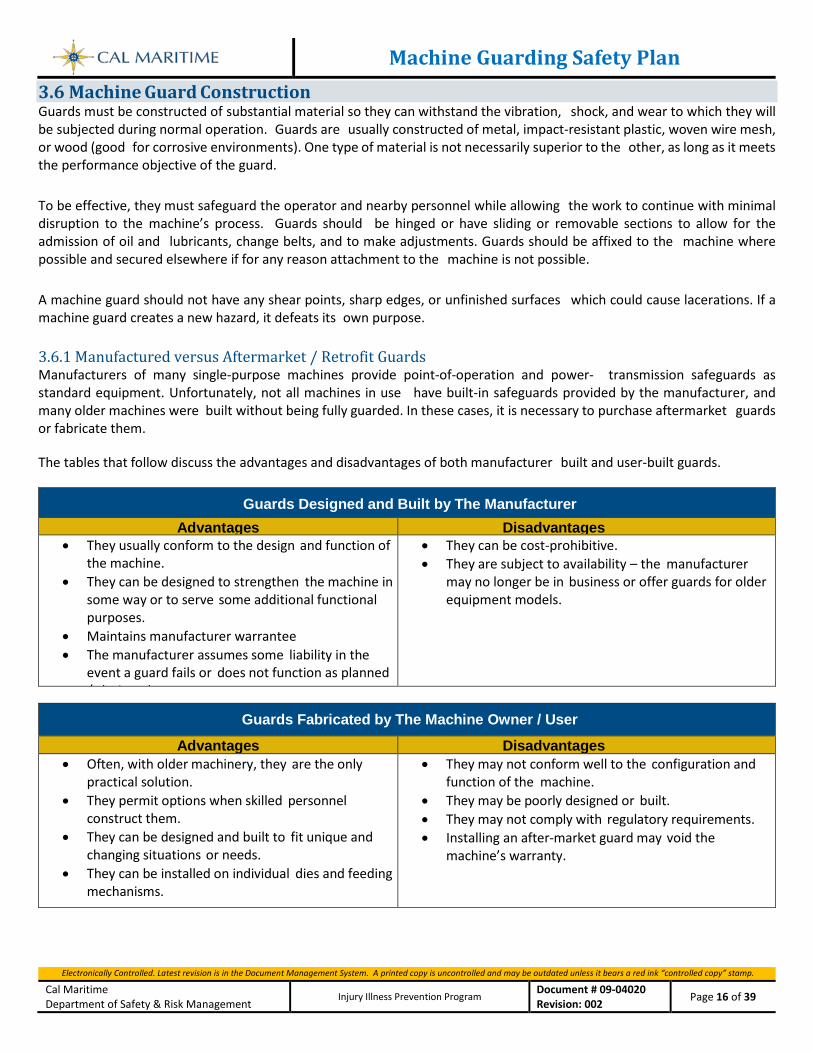
3.6 Machine Guard Construction Guards must be constructed of substantial material so they can withstand the vibration, shock, and wear to which they will be subjected during normal operation. Guards are usually constructed of metal, impact-resistant plastic, woven wire mesh, or wood (good for corrosive environments). One type of material is not necessarily superior to the other, as long as it meets the performance objective of the guard. To be effective, they must safeguard the operator and nearby personnel while allowing the work to continue with minimal disruption to the machine’s process. Guards should be hinged or have sliding or removable sections to allow for the admission of oil and lubricants, change belts, and to make adjustments. Guards should be affixed to the machine where possible and secured elsewhere if for any reason attachment to the machine is not possible. A machine guard should not have any shear points, sharp edges, or unfinished surfaces which could cause lacerations. If a machine guard creates a new hazard, it defeats its own purpose. 3.6.1 Manufactured versus Aftermarket / Retrofit Guards Manufacturers of many single-purpose machines provide point-of-operation and power- transmission safeguards as standard equipment. Unfortunately, not all machines in use have built-in safeguards provided by the manufacturer, and many older machines were built without being fully guarded. In these cases, it is necessary to purchase aftermarket guards or fabricate them. The tables that follow discuss the advantages and disadvantages of both manufacturer built and user-built guards.
Guards Designed and Built by The Manufacturer
Advantages Disadvantages • They usually conform to the design and function of
the machine. • They can be designed to strengthen the machine in
some way or to serve some additional functional purposes.
• Maintains manufacturer warrantee • The manufacturer assumes some liability in the
event a guard fails or does not function as planned / d i d
• They can be cost-prohibitive. • They are subject to availability – the manufacturer
may no longer be in business or offer guards for older equipment models.
Guards Fabricated by The Machine Owner / User
Advantages Disadvantages • Often, with older machinery, they are the only
practical solution. • They permit options when skilled personnel
construct them. • They can be designed and built to fit unique and
changing situations or needs. • They can be installed on individual dies and feeding
mechanisms.
• They may not conform well to the configuration and function of the machine.
• They may be poorly designed or built. • They may not comply with regulatory requirements. • Installing an after-market guard may void the
machine’s warranty.
Machine Guarding Safety Plan
Electronically Controlled. Latest revision is in the Document Management System. A printed copy is uncontrolled and may be outdated unless it bears a red ink “controlled copy” stamp.
Cal Maritime Department of Safety & Risk Management
Injury Illness Prevention Program Document # 09-04020 Revision: 002 Page 17 of 39
3.7 Safeguarding Devices A safeguarding device or control works by keeping the operator’s hands and body outside of the danger zone or by stopping the machine if the operator’s hands or body enter the danger zone. 3.7.1 Barriers and Gates A barrier is a device or object that provides a physical boundary to the hazard. Barrier devices are designed and constructed to enclose the hazard zone prior to the start of the hazardous portion of the machine cycle. They are held closed until completion of the cycle or until the machine has ceased motion. Gates are movable barriers that protect the operator at the point of operation before the machine cycle can be started. Gates are usually interlocked and, in many instances, designed to be operated with each machine cycle. If the gate does not fully close, the machine will not function
3.7.2 Presence-Sensing Devices An optical presence-sensing device uses a system of light beams or curtains that can interrupt the machine's operating cycle. If the sensing field is broken, the machine stops and will not cycle. This device must be used only on machines that can be stopped before the worker can reach into the danger area. An electromechanical presence-sensing device has a probe or contact bar that descends to a predetermined distance when the operator initiates the machine cycle. If there is an obstruction preventing it from descending its full pre-determined distance, the machine will not cycle.
3.7.3 Pressure-sensitive Devices When depressed, a pressure-sensitive device will deactivate the machine. Examples of pressure–sensitive devices are body bars, bump or contact strips, or mats.
3.7.4 Pullbacks and Restraints A pullback device is designed to protect the machine operator by keeping the operator's hands out of the danger zone during the hazardous portion of the machine cycle. It utilizes a series of cables attached to the operator’s hands, wrists, or arms which physically withdraws them before a cycle. The restraint device protects the operator by physically holding the operator's hands away from the hazard zone at all times. This is usually accomplished by the use of wrist straps.
3.8 Physical Restraint Device Both pullback and restraint devices are adjustable and therefore subject to human error. 3.8.1 Two-hand Control and Trip Devices A two-hand control requires constant, concurrent pressure to activate the machine. The operator’s hands are required to be at a safe location (on control buttons) and at a safe distance from the danger area while the machine completes its closing cycle. A two-hand trip requires concurrent application of both of the operator’s control buttons to activate the machine cycle, after which the hands are free. This device is used with machines equipped with full-revolution clutches. The trips must be placed far enough from the point of operation to make it impossible for the operators to move their hands from the trip buttons or handles into the point of operation before the first half of the cycle is completed to prevent them from being accidentally placed in the danger area prior to the slide/ram or blade reaching the full “down” position.
Machine Guarding Safety Plan
Electronically Controlled. Latest revision is in the Document Management System. A printed copy is uncontrolled and may be outdated unless it bears a red ink “controlled copy” stamp.
Cal Maritime Department of Safety & Risk Management
Injury Illness Prevention Program Document # 09-04020 Revision: 002 Page 18 of 39
3.9 Machine Safeguarding and Risk Reduction Methods The following safeguards and methods may be used in conjunction with primary machine guarding devices and controls to reduce the risk or create awareness of a hazard. Although these aids do not give complete protection from machine hazards, they may provide the operator with an extra margin of safety. Most designs / techniques for safeguarding machines focus on mechanical motion; however, machines create many non-mechanical hazards which should be protected against as well. 3.9.1 Access to Machinery Machines must be designed and constructed in a way that allows all necessary tasks to be carried out, but provides an acceptable level of protection for surrounding personnel. When feasible, access to hazardous machinery should be restricted to authorized personnel only. This can be accomplished by locating the machines and equipment in a separate room accessible only by key or keycard. Another option would be establishing a one-way traffic flow where users pass a check-in desk. Access may also include restrictions to certain hours and dates, although this is impossible to accomplish with a mechanical lock and key.
3.9.2 Anchoring Fixed Machinery A machine designed for a fixed location must be securely anchored to a building’s structure to prevent walking or moving. 3.9.3 Awareness Barriers and Signals Awareness barriers do not provide physical protection but serve as reminders to persons that they are approaching the danger area. An awareness barrier may move or be adjusted to allow entry of work pieces and personnel, but prevents anyone from reaching the hazard without awareness. In addition, it provides visual boundaries and indicates the hazard zone. Awareness signals provide a recognizable audible or visual signal of an approaching or present hazard. Indicator lamps, usually white, red and green, may be provided to indicate that the device is functioning. Indicator lights should be labeled or have distinct patterning or flashing. Audible awareness signals, like annunciators or bells, should have a distinctive sound and intensity such that they will be distinguished from the highest ambient noise level in the hazard zone. 3.9.4 Controls Control systems must be designed to enable the operator to interact safely with the machine. Ideally, a machine will have separate control zones for start-up functions, emergency stopping, stopping as a result of a safeguard device, and isolation or energy dissipation. Each control must require a deliberate action to initiate operation. In addition, controls must be:
• Permanently and clearly labeled and identified; • Located, positioned or safeguarded to prevent unintentional activation; • Designed to accommodate the foreseeable use of personal protective equipment (such as gloves and footwear); • Located out of reach of the hazard zones (except for emergency stop controls); • Mounted in a location that affords the operator safe operation and optimum visibility of the machinery; • Ergonomically designed; • Functionally grouped (i.e., the start button is located near the stop button); and • Indicated in a consistent manner. • Where the start/stop function is performed by means of a hold-to-run (jog) control, a separate stop control device
must be provided.
Machine Guarding Safety Plan
Electronically Controlled. Latest revision is in the Document Management System. A printed copy is uncontrolled and may be outdated unless it bears a red ink “controlled copy” stamp.
Cal Maritime Department of Safety & Risk Management
Injury Illness Prevention Program Document # 09-04020 Revision: 002 Page 19 of 39
3.10 Various styles of machine start/stop controls 3.10.1 Emergency Stop Devices All machines must be equipped with adequate means whereby the operator of the machine or other person can disconnect the power promptly in case of emergency. If the machine’s power switch is not located near the operator/point of operations, an emergency stop device must be provided that will immediately cut power to the equipment and cause motion or other operations to cease. Exception: The only exception to this rule is in the case of robotic control where power-disconnection could cause the robot to physically collapse under the force of gravity potentially causing injury. In such situations, the emergency stop may cause the robot to “freeze” motion but not remove power from its servo-motor controls. Emergency stop devices must be continuously operable, clearly identified, clearly visible and readily accessible. The device must be actuated by a single human action and initiate an immediate stop command. The emergency stop command must override all other functions and operations in all modes for hazardous motion. These devices must be manually reset to restart the machine. Examples of emergency stop devices are:
• Pushbutton. Pushbutton-type emergency stop devices must be installed so that it is unobstructed and can be actuated by the palm of the hand. The actuator of a pushbutton-operated device must be of the palm or mushroom-head type.
• Tripwire, cable or bar. A safety tripwire, cable or bar is a device located near the danger area of a machine. When pulled or pressed by the operator, the device deactivates the machine. The operator must be able to reach the device during emergency situations, so proper position is critical.
• Foot operated devices. Foot operated devices may be used when the foot-pedal must be continuously activated by the operator when they are at a safe location during machine operation. If the operator removes their foot from the pedal, it will act like an “emergency stop” device and immediately stop machine operation. The base of the foot-operated device must be anti-slip and capable of being permanently mounted. It’s location must not create a trip hazard and, once determined, bolted at the safe- location for safe operation
All emergency stop devices must be colored red. The background immediately around devices and disconnect switch actuators used as emergency stop devices must be colored yellow. The red/yellow combination is reserved exclusively for the emergency stop and emergency switching off applications.
3.10.2 Energy Isolation – Lockout Tagout (LOTO) When operators are required to place any part of their body into a hazardous zone, procedures for shutdown, energy isolation, and lock-out/block-out/tag-out must be established and followed. The process for safely controlling or dissipating hazardous stored energy must be identified for all machines as part of their design / installation for easy Energy Isolation – Lockout /Tagout. When servicing or adjustment operations must be performed with the power on and safe-guards removed (i.e., fine adjustments, testing and identifying the source of a problem), separate procedures must be developed to protect personnel during these situations.
Refer to Cal Maritime’s SRM Energy Isolation – Lockout/Tagout (LOTO) Program (available on the SRM website) for details
on how to conduct LOTO and design / develop equipment for ease of LOTO application. 3.10.3 Energy Source / Utility Interruption Machinery must be designed to prevent hazardous conditions resulting from interruption or excessive fluctuation of any energy source or utility used by the machine to maintain safe operation. In the event of loss of energy / utility, all devices whose permanent operation is required for safety (e.g., locking, clamping devices, cooling or heating devices, braking) must operate to maintain safety even with the utilities removed.
Machine Guarding Safety Plan
Electronically Controlled. Latest revision is in the Document Management System. A printed copy is uncontrolled and may be outdated unless it bears a red ink “controlled copy” stamp.
Cal Maritime Department of Safety & Risk Management
Injury Illness Prevention Program Document # 09-04020 Revision: 002 Page 20 of 39
3.10.4 Fail-Safe Design Fail-Safe Design is the design of interlocks and machine-control-logic wiring and programming to ensure the safety of the operator, personnel nearby and machine processes. A fail-safe system should be designed to default to its safest state of being in the event of any kind of “out-of-normal” failure condition, such as utility, wiring or component failures. The design assumption is that failure will eventually occur but when it does, it will fail in a manner as to mitigate injuries and losses.
3.10.5 Feeding and Ejection Methods Many feeding and ejection methods do not require operators to place their hands in the danger area. In some cases, no operator involvement is necessary after the machine is set up. In other situations, operators can manually feed the stock with the assistance of a feeding mechanism. Properly designed ejection methods do not require operator involvement after the machine starts to function. Using feeding and ejection methods does not eliminate the need for safeguarding. Guards and other devices must be used wherever they are necessary to provide protection from hazards. Feeding and ejection methods can be automatic or semiautomatic.
3.11 Various hand feeding and retrieval tools 3.11.1 Hand-Feeding and Retrieval Tools Hand-feeding and retrieval tools can place or remove stock. Hand-feeding tools are intended for placing and removing materials into the in the danger area of a machine. Hand-feeding tools are not a point-of-operation guard or protection device and shall not be used in lieu of appropriate safeguards, but as a supplement. A typical use would be for reaching in the danger area of a press or press brake. Another example would be a push stick or block used when feeding stock into a saw blade. When it becomes necessary for hands to be in close proximity to the blade, the push stick or block may provide a few inches of safety and prevent a severe injury. 3.11.2 Location / Distance To consider a part of a machine to be safeguarded by location, the dangerous moving part of a machine must be located in areas that are not accessible to operators or personnel and do not present a hazard during the normal operation of the machine. This may be accomplished by using enclosure walls or fences. Another possible solution is to have dangerous parts located high enough to be out of the normal reach of any worker. Locating a machine in a separate and restricted access area may qualify as guarding by location. 3.11.3 Shields Shields can protect workers from flying particles, chips, sparks, and oils, but do not provide protection from machine hazards. Shields must not interfere with the workers ability to operate the machine or reduce the operator’s field of vision.
3.12 Signs, Labels and Color Coding Color-coding certain parts of a machine will make the employee aware of potentially hazardous conditions. Orange should be used to identify hazardous parts of the machines, such as exposed edges, pulleys, gears, rollers, cutting devices, power jaws, etc. Yellow should be used to identify physical hazards such as striking against, stumbling, falling, and caught in- between. Warnings, stickers, labels and safety reminders should be affixed to highlight the dangerous areas. Equipment-specific operating procedures should be established and posted on/near each machine. If possible, have the equipment’s operating manual available to workers.
Machine Guarding Safety Plan
Electronically Controlled. Latest revision is in the Document Management System. A printed copy is uncontrolled and may be outdated unless it bears a red ink “controlled copy” stamp.
Cal Maritime Department of Safety & Risk Management
Injury Illness Prevention Program Document # 09-04020 Revision: 002 Page 21 of 39
3.13 Machine Operator Procedures 3.13.1 Users of Machines with Safe-Guards Users of machines that are provided with guards / interlocks by their manufacturer must:
• Obtain training on any equipment that they are not familiar with by asking a knowledgeable person on the equipment’s safe use / operation
• Complete required training and obtain authorization prior to operating machines and equipment • Inspect machines and equipment before each use to verify they are in good operating condition with all the required
guards in place • Ensure machine guards are properly installed before using the machine • Not use a machine when manufacturer-supplied guards are not installed on it • Recognize through training the locations where guards and interlocks should be installed on any machine • Bring to management’s attention when an unguarded machine location should be guarded • Understand and practice approved machine safeguarding methods • Observe all safety protocols and any standard operating procedures • Wear all appropriate personal protective equipment (PPE) • Report machine safeguarding / interlock malfunctions or problems to a supervisor / PI immediately • Report unauthorized or unsafe use of machines and equipment to a supervisor / PI • Never defeat or remove guards or interlocks or other safety devices • Never operate machines without safeguards / interlocks in place and confirmed functioning properly. • Never bypass a machine guard or interlock without following strict safety- procedures to ensure equal measure of
safety in the workplace
3.14 Safeguarding Assessment The checklist in this program and SRM can assist in determining the need for machine guards or other safeguarding methods. When conducting a machine guarding assessment, it is imperative to analyze all potential hazards associated with normal operating procedures: start-up, shutdown, setup, inspection, servicing, maintenance and lockout/tagout. It is also important to consider unusual operations, equipment malfunction, broken tooling, and foreseeable misuse of the equipment. Similar machines may be used as a starting point when tasks and hazards are comparable. Using this information does not eliminate the need to follow a risk assessment process for the specific conditions of use. For example, when a shear used for cutting plastic is compared with a shear used for cutting metal, the risks associated with the different materials should be assessed. The extent of safeguarding needs can vary based on numerous factors, such as degree of exposure and the potential for harm. The necessity for guarding equipment used by inexperienced operators exceeds what would typically be required in a professional shop. A basic risk assessment can assist with determining this extent. The assessment should be conducted using logical deduction and a qualitative assessment of the following:
• Who is exposed? Machines used by students should be given the most safeguards, while professional equipment used by seasoned machinists may be outfitted with the minimal amount required for compliance. For example, a lathe used primarily by students should be guarded with a lead screw cover; this is not normally seen or accepted in a professional shop. If the equipment is used by both students and professionals, guard for the riskiest population.
• How many people use the equipment? Multiple users increase the chances that equipment could be set-up incorrectly or poorly maintained. The more people who use the equipment, the more the equipment is exposed to a variety of worker behaviors.
Machine Guarding Safety Plan
Electronically Controlled. Latest revision is in the Document Management System. A printed copy is uncontrolled and may be outdated unless it bears a red ink “controlled copy” stamp.
Cal Maritime Department of Safety & Risk Management
Injury Illness Prevention Program Document # 09-04020 Revision: 002 Page 22 of 39
• What is the experience level and knowledge of the average user? Operators who have little or no prior experience are at a higher risk of injury and would benefit from additional safeguards.
• What is the frequency and duration of equipment use? The more a piece of equipment is used, the probability that an accident will occur increases. On the opposite end of the spectrum, operators who rarely use a piece of equipment may be at an increased risk of injury because they may forget the specifics of operation or nuances of safe-operation of the machine.
• What is the probability that an accident will occur? Additional safeguarding methods should be applied when the probability of an accident, incident or mishap is imminent or extremely likely.
• What would be the severity of an accident? The areas and opportunities to cause serious injuries or illnesses should be given the most consideration
Machine Guarding Safety Plan
Electronically Controlled. Latest revision is in the Document Management System. A printed copy is uncontrolled and may be outdated unless it bears a red ink “controlled copy” stamp.
Cal Maritime Department of Safety & Risk Management
Injury Illness Prevention Program Document # 09-04020 Revision: 002 Page 23 of 39
4.0 Training Requirements Effective dissemination of safety information lies at the very heart of a successful Injury and Illness Prevention Program. It is essential to provide training for employees concerning general safe work practices as well as specific instruction with respect to hazards unique to each employee’s job assignment.
Training content is determined by the Department of Safety and Risk Management, as well as Department Management which is based upon observed hazards, type of equipment, Department need, and work requirements.
• Providing training from within the department as a part of academic programming, or • Training provided by CSU-System, or • Training provided by Cal Maritime SRM, or • A training provider outside the University.
Note: All outside trainer venders are to be reviewed and content approved by SRM. The Department of Safety and Risk Management, in conjunction with various departments have developed training programs designed to meet general safe work practice requirements. These programs are elements of larger programs which service broad campus needs.
Training is to be documented and kept in a readily accessible location by the Department designee for access reference as needed by Department Management, Department of Safety & Risk Management, or regulatory agency (e.g. CalOSHA). Submit the completed training roster of attendees to the Department of Safety & Risk Management.
Refer to Cal/OSHA Safety & Health Training and Instruction Requirements as outlined.
4.1 Personnel Operating Machines Personnel who operate machines with hazards must be trained on these hazards and their safeguards. They must be trained upon initial assignment, when any new safeguards are put in place or when new hazards are recognized or created by new machine operations / processes. Training must include the following:
• Their “roles and responsibilities” as outlined in that section of this program • Identification and description of the hazards associated with the machine; • The safeguards, how they provide protection, and the hazards being controlled for which the safeguards are
intended; • Precautions to take when machine is unguarded during maintenance and repair; and • What to do and who to contact if a guard is damaged, missing, or defective.
4.2 Retraining should be provided whenever • There is a change in job assignments; • A change in machines, equipment, or processes that presents a new hazard; • An inspection reveals, or whenever the “Equipment Owner” has reason to believe, that there are deviations from
or inadequacies in the operator's knowledge of related procedures; or • An injury or near-miss occurs related to a machine safeguarding hazard or deficiency which provides a learning
opportunity for affected personnel.
4.3 Managers, Supervisors, PIs, “Equipment Owner” Managers, supervisors, and PIs (collectively referred to as the “Equipment Owner”) who purchase or operate machines and / or supervise others who do, must be trained on:
• Their “roles and responsibilities” as outlined in that section of this program • The contents of how to identify safeguards, how they provide protection, and the hazards being controlled for
which the safeguards are intended; • The resources available to them from EH&S for support in implementing this program.
Machine Guarding Safety Plan
Electronically Controlled. Latest revision is in the Document Management System. A printed copy is uncontrolled and may be outdated unless it bears a red ink “controlled copy” stamp.
Cal Maritime Department of Safety & Risk Management
Injury Illness Prevention Program Document # 09-04020 Revision: 002 Page 24 of 39
4.4 Maintenance and Service Personnel Maintenance and service personnel must be trained on:
• Their “roles and responsibilities” as outlined in that section of this program • The contents of how to identify safeguards, how they provide protection, and the hazards being controlled for
which the safeguards are intended; • The resources available to them from SRM for support in implementing this program. • Lockout and tagout machines and equipment prior to removing or bypassing guards (implement Cal Maritime
Energy Isolation - Lockout Tagout Program, as necessary)
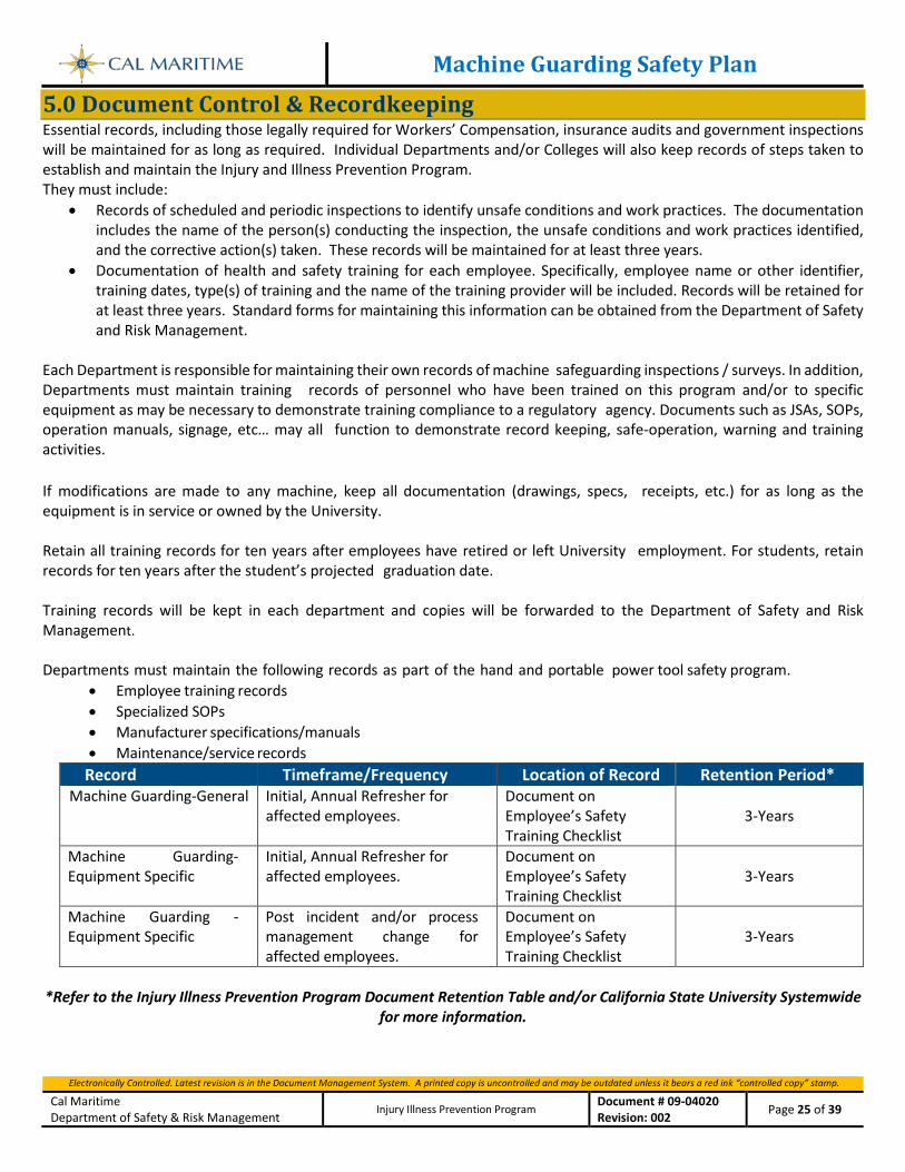
Machine Guarding Safety Plan
Electronically Controlled. Latest revision is in the Document Management System. A printed copy is uncontrolled and may be outdated unless it bears a red ink “controlled copy” stamp.
Cal Maritime Department of Safety & Risk Management
Injury Illness Prevention Program Document # 09-04020 Revision: 002 Page 25 of 39
5.0 Document Control & Recordkeeping Essential records, including those legally required for Workers’ Compensation, insurance audits and government inspections will be maintained for as long as required. Individual Departments and/or Colleges will also keep records of steps taken to establish and maintain the Injury and Illness Prevention Program. They must include:
• Records of scheduled and periodic inspections to identify unsafe conditions and work practices. The documentation includes the name of the person(s) conducting the inspection, the unsafe conditions and work practices identified, and the corrective action(s) taken. These records will be maintained for at least three years.
• Documentation of health and safety training for each employee. Specifically, employee name or other identifier, training dates, type(s) of training and the name of the training provider will be included. Records will be retained for at least three years. Standard forms for maintaining this information can be obtained from the Department of Safety and Risk Management.
Each Department is responsible for maintaining their own records of machine safeguarding inspections / surveys. In addition, Departments must maintain training records of personnel who have been trained on this program and/or to specific equipment as may be necessary to demonstrate training compliance to a regulatory agency. Documents such as JSAs, SOPs, operation manuals, signage, etc… may all function to demonstrate record keeping, safe-operation, warning and training activities. If modifications are made to any machine, keep all documentation (drawings, specs, receipts, etc.) for as long as the equipment is in service or owned by the University. Retain all training records for ten years after employees have retired or left University employment. For students, retain records for ten years after the student’s projected graduation date. Training records will be kept in each department and copies will be forwarded to the Department of Safety and Risk Management. Departments must maintain the following records as part of the hand and portable power tool safety program.
• Employee training records • Specialized SOPs • Manufacturer specifications/manuals • Maintenance/service records
Record Timeframe/Frequency Location of Record Retention Period* Machine Guarding-General Initial, Annual Refresher for
affected employees. Document on Employee’s Safety Training Checklist
3-Years
Machine Guarding-Equipment Specific
Initial, Annual Refresher for affected employees.
Document on Employee’s Safety Training Checklist
3-Years
Machine Guarding -Equipment Specific
Post incident and/or process management change for affected employees.
Document on Employee’s Safety Training Checklist
3-Years
*Refer to the Injury Illness Prevention Program Document Retention Table and/or California State University Systemwide
for more information.
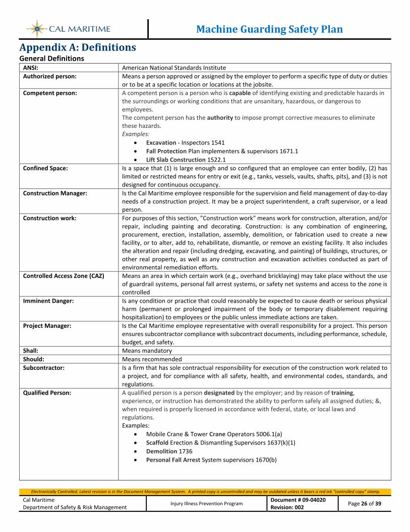
Machine Guarding Safety Plan
Electronically Controlled. Latest revision is in the Document Management System. A printed copy is uncontrolled and may be outdated unless it bears a red ink “controlled copy” stamp.
Cal Maritime Department of Safety & Risk Management
Injury Illness Prevention Program Document # 09-04020 Revision: 002 Page 26 of 39
Appendix A: Definitions General Definitions
ANSI: American National Standards Institute Authorized person: Means a person approved or assigned by the employer to perform a specific type of duty or duties
or to be at a specific location or locations at the jobsite. Competent person: A competent person is a person who is capable of identifying existing and predictable hazards in
the surroundings or working conditions that are unsanitary, hazardous, or dangerous to employees. The competent person has the authority to impose prompt corrective measures to eliminate these hazards. Examples:
• Excavation - Inspectors 1541 • Fall Protection Plan implementers & supervisors 1671.1 • Lift Slab Construction 1522.1
Confined Space: Is a space that (1) is large enough and so configured that an employee can enter bodily, (2) has limited or restricted means for entry or exit (e.g., tanks, vessels, vaults, shafts, pits), and (3) is not designed for continuous occupancy.
Construction Manager: Is the Cal Maritime employee responsible for the supervision and field management of day-to-day needs of a construction project. It may be a project superintendent, a craft supervisor, or a lead person.
Construction work: For purposes of this section, "Construction work" means work for construction, alteration, and/or repair, including painting and decorating. Construction: is any combination of engineering, procurement, erection, installation, assembly, demolition, or fabrication used to create a new facility, or to alter, add to, rehabilitate, dismantle, or remove an existing facility. It also includes the alteration and repair (including dredging, excavating, and painting) of buildings, structures, or other real property, as well as any construction and excavation activities conducted as part of environmental remediation efforts.
Controlled Access Zone (CAZ) Means an area in which certain work (e.g., overhand bricklaying) may take place without the use of guardrail systems, personal fall arrest systems, or safety net systems and access to the zone is controlled
Imminent Danger: Is any condition or practice that could reasonably be expected to cause death or serious physical harm (permanent or prolonged impairment of the body or temporary disablement requiring hospitalization) to employees or the public unless immediate actions are taken.
Project Manager: Is the Cal Maritime employee representative with overall responsibility for a project. This person ensures subcontractor compliance with subcontract documents, including performance, schedule, budget, and safety.
Shall: Means mandatory Should: Means recommended Subcontractor: Is a firm that has sole contractual responsibility for execution of the construction work related to
a project, and for compliance with all safety, health, and environmental codes, standards, and regulations.
Qualified Person: A qualified person is a person designated by the employer; and by reason of training, experience, or instruction has demonstrated the ability to perform safely all assigned duties; &, when required is properly licensed in accordance with federal, state, or local laws and regulations. Examples:
• Mobile Crane & Tower Crane Operators 5006.1(a) • Scaffold Erection & Dismantling Supervisors 1637(k)(1) • Demolition 1736 • Personal Fall Arrest System supervisors 1670(b)
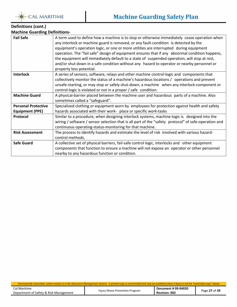
Machine Guarding Safety Plan
Electronically Controlled. Latest revision is in the Document Management System. A printed copy is uncontrolled and may be outdated unless it bears a red ink “controlled copy” stamp.
Cal Maritime Department of Safety & Risk Management
Injury Illness Prevention Program Document # 09-04020 Revision: 002 Page 27 of 39
Definitions (cont.) Machine Guarding Definitions-
Fail Safe A term used to define how a machine is to stop or otherwise immediately cease operation when any interlock or machine guard is removed, or any fault-condition is detected by the equipment’s operation logic, or one or more utilities are interrupted during equipment operation. The “fail safe” design of equipment ensures that if any abnormal condition happens, the equipment will immediately default to a state of suspended operation, will stop at rest, and/or shut down in a safe condition without any hazard to operator or nearby personnel or property loss potential.
Interlock A series of sensors, software, relays and other machine control-logic and components that collectively monitor the status of a machine’s hazardous locations / operations and prevent unsafe-starting, or may stop or safely shut-down, a machine when any interlock-component or control-logic is violated or not in a proper / safe condition.
Machine Guard A physical-barrier placed between the machine user and hazardous parts of a machine. Also sometimes called a “safeguard”.
Personal Protective Equipment (PPE)
Specialized clothing or equipment worn by employees for protection against health and safety hazards associated with their work- place or specific work-tasks
Protocol Similar to a procedure, when designing interlock systems, machine-logic is designed into the wiring / software / sensor selection that is all part of the “safety protocol” of safe-operation and continuous operating-status-monitoring for that machine.
Risk Assessment The process to identify hazards and estimate the level of risk involved with various hazard-control methods.
Safe Guard A collective set of physical barriers, fail-safe control logic, interlocks and other equipment components that function to ensure a machine will not expose an operator or other personnel nearby to any hazardous function or condition.
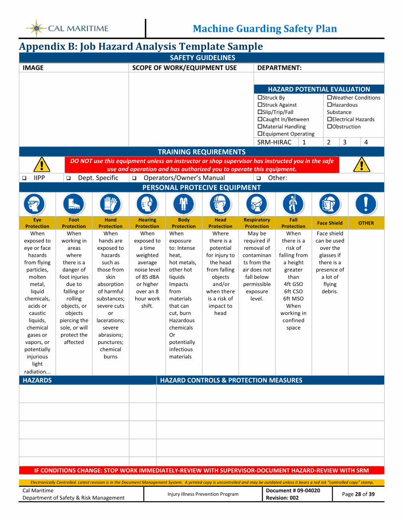
Machine Guarding Safety Plan
Electronically Controlled. Latest revision is in the Document Management System. A printed copy is uncontrolled and may be outdated unless it bears a red ink “controlled copy” stamp.
Cal Maritime Department of Safety & Risk Management
Injury Illness Prevention Program Document # 09-04020 Revision: 002 Page 28 of 39
Appendix B: Job Hazard Analysis Template Sample SAFETY GUIDELINES
IMAGE SCOPE OF WORK/EQUIPMENT USE DEPARTMENT:
HAZARD POTENTIAL EVALUATION Struck By Struck Against Slip/Trip/Fall Caught In/Between Material Handling Equipment Operating
Weather Conditions Hazardous Substance Electrical Hazards Obstruction
SRM-HIRAC 1 2 3 4 TRAINING REQUIREMENTS
DO NOT use this equipment unless an instructor or shop supervisor has instructed you in the safe
use and operation and has authorized you to operate this equipment. IIPP Dept. Specific Operators/Owner’s Manual Other:
PERSONAL PROTECIVE EQUIPMENT
Eye
Protection Foot
Protection Hand
Protection Hearing
Protection Body
Protection Head
Protection Respiratory Protection
Fall Protection Face Shield OTHER
When exposed to eye or face
hazards from flying particles, molten metal, liquid
chemicals, acids or caustic liquids,
chemical gases or
vapors, or potentially injurious
light radiation...
When working in
areas where
there is a danger of
foot injuries due to
falling or rolling
objects, or objects
piercing the sole, or will protect the
affected
When hands are
exposed to hazards such as
those from skin
absorption of harmful
substances; severe cuts
or lacerations;
severe abrasions; punctures; chemical
burns
When exposed to
a time weighted average
noise level of 85 dBA or higher over an 8 hour work
shift.
When exposure to: Intense heat, hot metals, other hot liquids Impacts from materials that can cut, burn Hazardous chemicals Or potentially infectious materials
Where there is a potential
for injury to the head
from falling objects and/or
when there is a risk of impact to
head
May be required if removal of
contaminants from the air does not fall below
permissible exposure
level.
When there is a
risk of falling from
a height greater
than 4ft GSO 6ft CSO 6ft MSO
When working in confined
space
Face shield can be used
over the glasses if there is a
presence of a lot of flying
debris.
HAZARDS HAZARD CONTROLS & PROTECTION MEASURES
IF CONDITIONS CHANGE: STOP WORK IMMEDIATELY-REVIEW WITH SUPERVISOR-DOCUMENT HAZARD-REVIEW WITH SRM
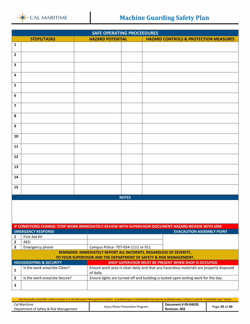
Machine Guarding Safety Plan
Electronically Controlled. Latest revision is in the Document Management System. A printed copy is uncontrolled and may be outdated unless it bears a red ink “controlled copy” stamp.
Cal Maritime Department of Safety & Risk Management
Injury Illness Prevention Program Document # 09-04020 Revision: 002 Page 29 of 39
SAFE OPERATING PROCEEDURES
STEPS/TASKS HAZARD POTENTIAL HAZARD CONTROLS & PROTECTION MEASURES 1
2
3
4
5
6
7
8
9
10
11
12
13
14
15
NOTES IF CONDITIONS CHANGE: STOP WORK IMMEDIATELY-REVIEW WITH SUPERVISOR-DOCUMENT HAZARD-REVIEW WITH SRM EMERGENCY RESPONSE EVACAUTION ASSEMBLY POINT 1 First Aid Kit 2 AED 3 Emergency phone Campus Police- 707-654-1111 or 911
REMINDER: IMMEDIATELY REPORT ALL INCIDENTS, REGARDLESS OF SEVERITY, TO YOUR SUPERVISOR AND THE DEPARTMENT OF SAFETY & RISK MANAGEMENT.
HOUSEKEEPING & SECURITY SHOP SUPERVISOR MUST BE PRESENT WHEN SHOP IS OCCUPIED
1 Is the work area/site Clean? Ensure work area is clean daily and that any hazardous materials are properly disposed of daily
2 Is the work area/site Secure? Ensure lights are turned off and building is locked upon exiting work for the day.
3
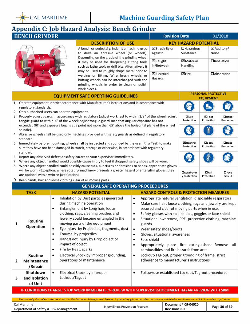
Machine Guarding Safety Plan
Electronically Controlled. Latest revision is in the Document Management System. A printed copy is uncontrolled and may be outdated unless it bears a red ink “controlled copy” stamp.
Cal Maritime Department of Safety & Risk Management
Injury Illness Prevention Program Document # 09-04020 Revision: 002 Page 30 of 39
Appendix C: Job Hazard Analysis: Bench Grinder BENCH GRINDER Revision Date 01/2018
DESCRIPTION OF USE KEY HAZARD POTENTIAL A bench or pedestal grinder is a machine used to drive an abrasive wheel (or wheels). Depending on the grade of the grinding wheel it may be used for sharpening cutting tools such as lathe tools or drill bits. Alternatively it may be used to roughly shape metal prior to welding or fitting. Wire brush wheels or buffing wheels can be interchanged with the grinding wheels in order to clean or polish work pieces.
Struck By or Against
Hazardous Substance
Auditory/ Noise
Caught In/Between
Material Handling
Inhalation
Electrical Hazards
Fire Absorption
EQUIPMENT SAFE OPERTING GUIDELINES PERSONAL PROTECTIVE EQUIPMENT
1. Operate equipment in strict accordance with Manufacturer’s instructions and in accordance with regulatory standards.
2. Only authorized users can operate equipment. 3. Properly adjust guards in accordance with regulatory (adjust work rest to within 1/8” of the wheel; adjust
tongue guard to within ¼” of the wheel; adjust tongue guard such that angular exposure has not exceeded 90° and exposure begins at a point not more than 65° above the horizontal plane of the wheel spindle).
4. Abrasive wheels shall be used only machines provided with safety guards as defined in regulatory standard
5. Immediately before mounting, wheels shall be inspected and sounded by the user (Ring Test) to make sure they have not been damaged in transit, storage or otherwise, in accordance with regulatory standard.
6. Report any observed defect or safety hazard to your supervisor immediately. 7. Where any object handled would possibly cause injury to feet if dropped, safety shoes will be worn. 8. Where any object handled could possibly cause cuts, punctures or abrasions to hands, appropriate gloves
will be worn. (Exception: where rotating machinery presents a greater hazard of entangling gloves, they are optional with a written justification).
9. Keep hands, hair and loose clothing clear of all moving parts.
Eye
Protection Foot
Protection Hand
Protection
Hearing Protection
Body Protection
Head Protection
Respiratory Protection
Fall Protection
Face Shield
GENERAL SAFE OPERATING PROCEEDURES
TASK HAZARD POTENTIAL HAZARD CONTROLS & PROTECTION MEASURES
1 Routine Operation
• Inhalation by Dust particles generated during machine operation
• Entanglement by Long hair, loose clothing, rags, cleaning brushes and jewelry could become entangled in the moving parts of the equipment.
• Eye Injury by Projectiles, fragments, dust • Trauma by projectiles • Hand/Foot Injury by Drop object or
impact of object • Fire by Heat, sparks
• Appropriate natural ventilation, disposable respirators • Make sure hair, loose clothing, rags and jewelry are kept
secured and clear of moving parts when in use. • Safety glasses with side-shields, goggles or face shield • Situational awareness, PPE, protective clothing, machine
guards • Wear safety shoes/boots • Gloves, situational awareness • Face shield • Appropriately place fire extinguisher. Remove all
combustibles and fire hazards from area
2 Routine
Maintenance/Repair
• Electrical Shock by Improper grounding, operations or maintenance
• Lockout/Tag‐out, proper grounding of frame, strict adherence to manufacturer’s instructions
3 Shutdown
and Isolation of Unit
• Electrical Shock by Improper Lockout/Tagout
• Follow/use established Lockout/Tag‐out procedures
IF CONDITIONS CHANGE: STOP WORK IMMEDIATELY-REVIEW WITH SUPERVISOR-DOCUMENT HAZARD-REVIEW WITH SRM
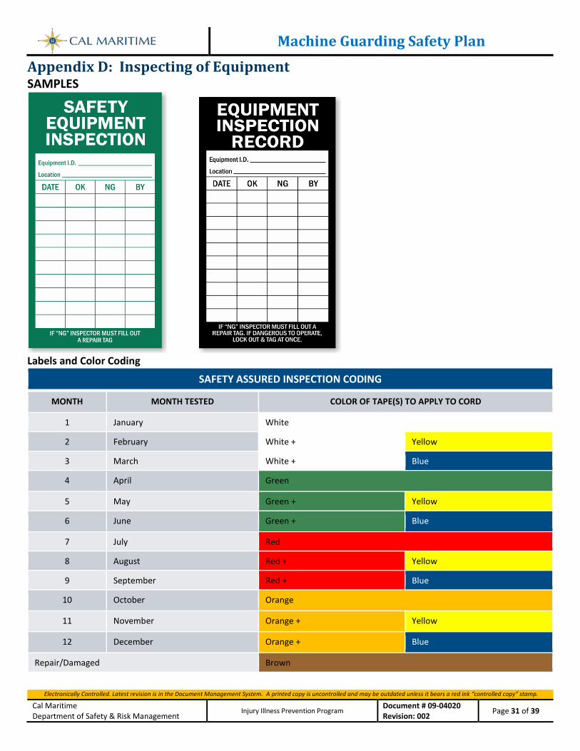
Machine Guarding Safety Plan
Electronically Controlled. Latest revision is in the Document Management System. A printed copy is uncontrolled and may be outdated unless it bears a red ink “controlled copy” stamp.
Cal Maritime Department of Safety & Risk Management
Injury Illness Prevention Program Document # 09-04020 Revision: 002 Page 31 of 39
Appendix D: Inspecting of Equipment SAMPLES
Labels and Color Coding
SAFETY ASSURED INSPECTION CODING
MONTH MONTH TESTED COLOR OF TAPE(S) TO APPLY TO CORD
1 January White
2 February White + Yellow
3 March White + Blue
4 April Green
5 May Green + Yellow
6 June Green + Blue
7 July Red
8 August Red + Yellow
9 September Red + Blue
10 October Orange
11 November Orange + Yellow
12 December Orange + Blue
Repair/Damaged Brown
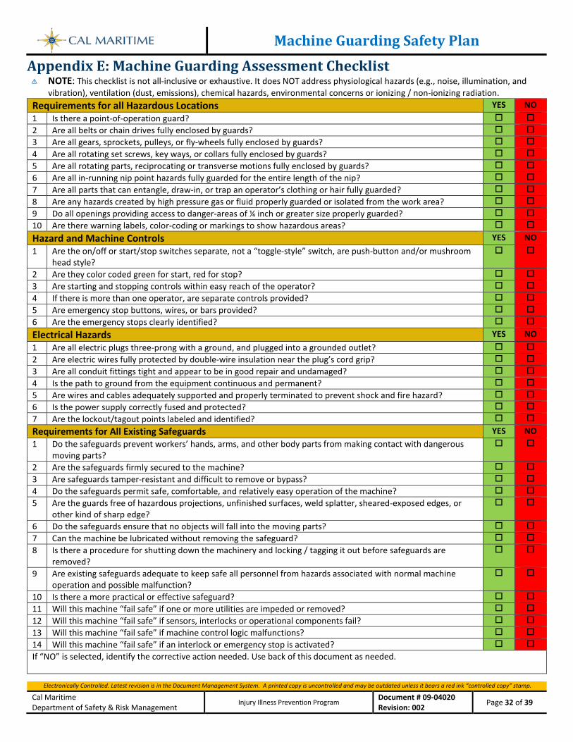
Machine Guarding Safety Plan
Electronically Controlled. Latest revision is in the Document Management System. A printed copy is uncontrolled and may be outdated unless it bears a red ink “controlled copy” stamp.
Cal Maritime Department of Safety & Risk Management
Injury Illness Prevention Program Document # 09-04020 Revision: 002 Page 32 of 39
Appendix E: Machine Guarding Assessment Checklist NOTE: This checklist is not all-inclusive or exhaustive. It does NOT address physiological hazards (e.g., noise, illumination, and
vibration), ventilation (dust, emissions), chemical hazards, environmental concerns or ionizing / non-ionizing radiation. Requirements for all Hazardous Locations YES NO 1 Is there a point-of-operation guard? 2 Are all belts or chain drives fully enclosed by guards? 3 Are all gears, sprockets, pulleys, or fly-wheels fully enclosed by guards? 4 Are all rotating set screws, key ways, or collars fully enclosed by guards? 5 Are all rotating parts, reciprocating or transverse motions fully enclosed by guards? 6 Are all in-running nip point hazards fully guarded for the entire length of the nip? 7 Are all parts that can entangle, draw-in, or trap an operator’s clothing or hair fully guarded? 8 Are any hazards created by high pressure gas or fluid properly guarded or isolated from the work area? 9 Do all openings providing access to danger-areas of ¼ inch or greater size properly guarded? 10 Are there warning labels, color-coding or markings to show hazardous areas? Hazard and Machine Controls YES NO 1 Are the on/off or start/stop switches separate, not a “toggle-style” switch, are push-button and/or mushroom
head style?
2 Are they color coded green for start, red for stop? 3 Are starting and stopping controls within easy reach of the operator? 4 If there is more than one operator, are separate controls provided? 5 Are emergency stop buttons, wires, or bars provided? 6 Are the emergency stops clearly identified? Electrical Hazards YES NO 1 Are all electric plugs three-prong with a ground, and plugged into a grounded outlet? 2 Are electric wires fully protected by double-wire insulation near the plug’s cord grip? 3 Are all conduit fittings tight and appear to be in good repair and undamaged? 4 Is the path to ground from the equipment continuous and permanent? 5 Are wires and cables adequately supported and properly terminated to prevent shock and fire hazard? 6 Is the power supply correctly fused and protected? 7 Are the lockout/tagout points labeled and identified? Requirements for All Existing Safeguards YES NO 1 Do the safeguards prevent workers’ hands, arms, and other body parts from making contact with dangerous
moving parts?
2 Are the safeguards firmly secured to the machine? 3 Are safeguards tamper-resistant and difficult to remove or bypass? 4 Do the safeguards permit safe, comfortable, and relatively easy operation of the machine? 5 Are the guards free of hazardous projections, unfinished surfaces, weld splatter, sheared-exposed edges, or
other kind of sharp edge?
6 Do the safeguards ensure that no objects will fall into the moving parts? 7 Can the machine be lubricated without removing the safeguard? 8 Is there a procedure for shutting down the machinery and locking / tagging it out before safeguards are
removed?
9 Are existing safeguards adequate to keep safe all personnel from hazards associated with normal machine operation and possible malfunction?
10 Is there a more practical or effective safeguard? 11 Will this machine “fail safe” if one or more utilities are impeded or removed? 12 Will this machine “fail safe” if sensors, interlocks or operational components fail? 13 Will this machine “fail safe” if machine control logic malfunctions? 14 Will this machine “fail safe” if an interlock or emergency stop is activated? If “NO” is selected, identify the corrective action needed. Use back of this document as needed.
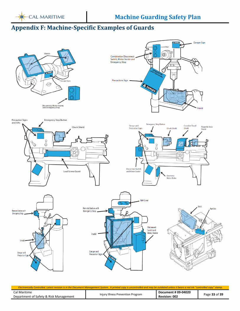
Machine Guarding Safety Plan
Electronically Controlled. Latest revision is in the Document Management System. A printed copy is uncontrolled and may be outdated unless it bears a red ink “controlled copy” stamp.
Cal Maritime Department of Safety & Risk Management
Injury Illness Prevention Program Document # 09-04020 Revision: 002 Page 33 of 39
Appendix F: Machine-Specific Examples of Guards
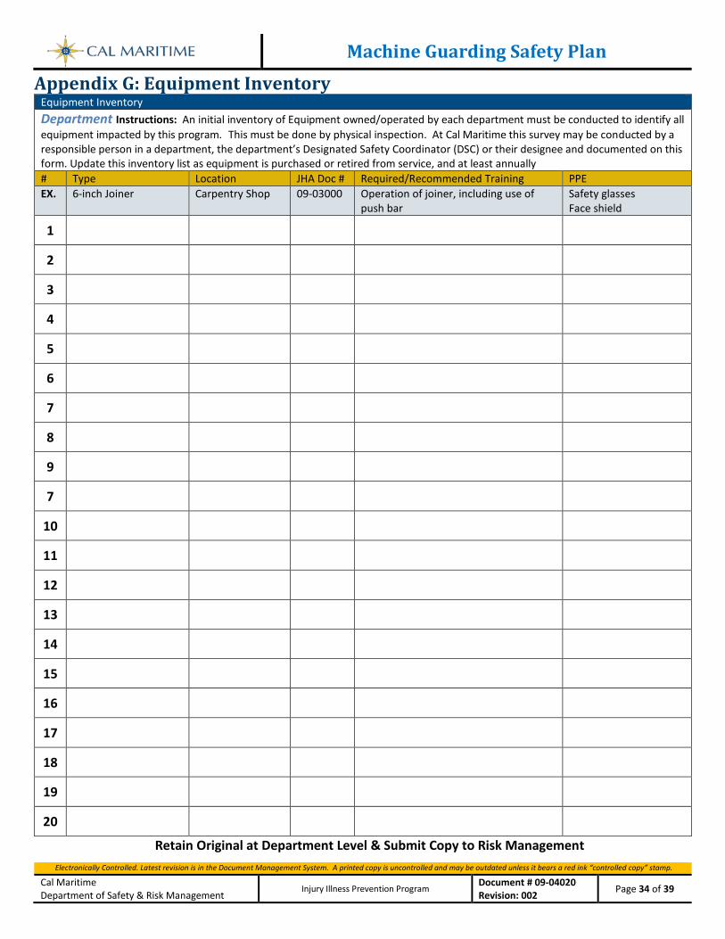
Machine Guarding Safety Plan
Electronically Controlled. Latest revision is in the Document Management System. A printed copy is uncontrolled and may be outdated unless it bears a red ink “controlled copy” stamp.
Cal Maritime Department of Safety & Risk Management
Injury Illness Prevention Program Document # 09-04020 Revision: 002 Page 34 of 39
Appendix G: Equipment Inventory Equipment Inventory
Department Instructions: An initial inventory of Equipment owned/operated by each department must be conducted to identify all equipment impacted by this program. This must be done by physical inspection. At Cal Maritime this survey may be conducted by a responsible person in a department, the department’s Designated Safety Coordinator (DSC) or their designee and documented on this form. Update this inventory list as equipment is purchased or retired from service, and at least annually # Type Location JHA Doc # Required/Recommended Training PPE EX. 6-inch Joiner Carpentry Shop 09-03000 Operation of joiner, including use of
push bar Safety glasses Face shield
1 2 3 4 5 6 7 8 9 7
10 11 12 13 14 15 16 17 18 19 20
Retain Original at Department Level & Submit Copy to Risk Management
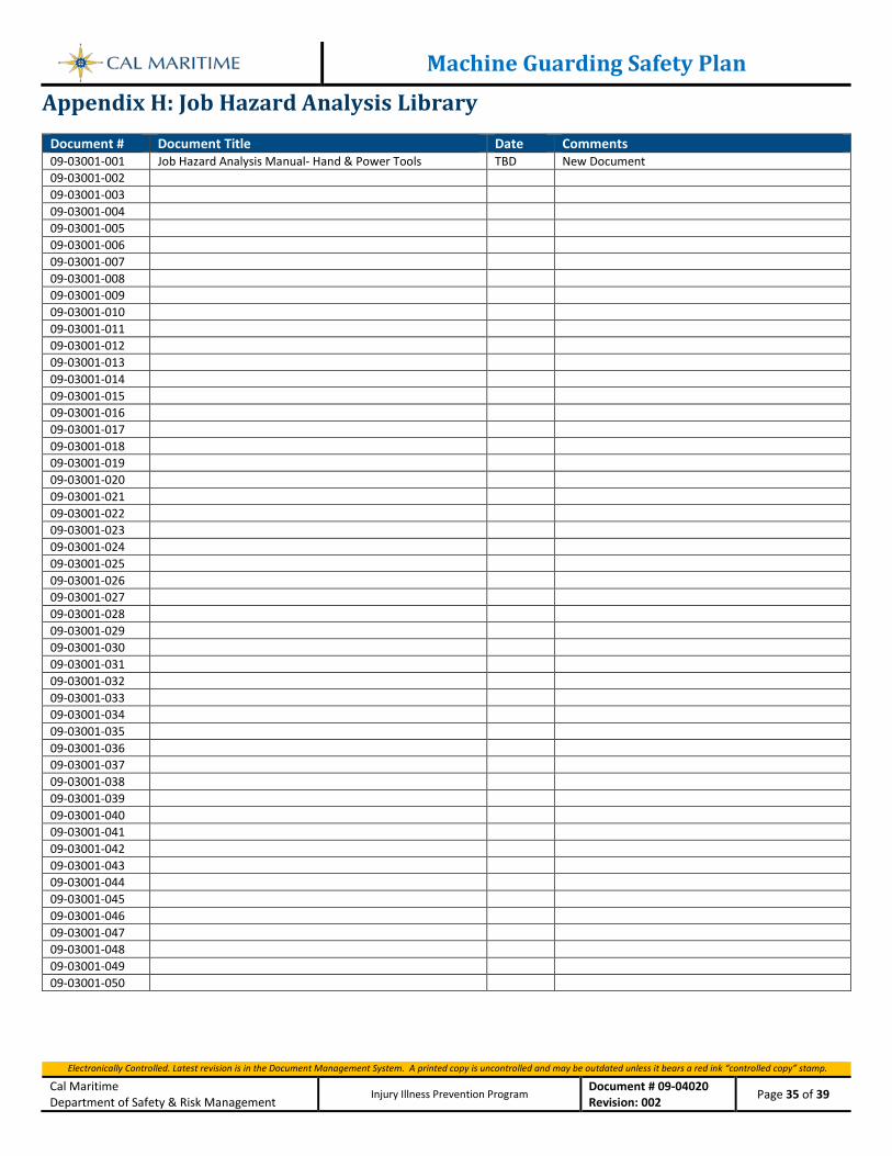
Machine Guarding Safety Plan
Electronically Controlled. Latest revision is in the Document Management System. A printed copy is uncontrolled and may be outdated unless it bears a red ink “controlled copy” stamp.
Cal Maritime Department of Safety & Risk Management
Injury Illness Prevention Program Document # 09-04020 Revision: 002 Page 35 of 39
Appendix H: Job Hazard Analysis Library
Document # Document Title Date Comments 09-03001-001 Job Hazard Analysis Manual- Hand & Power Tools TBD New Document 09-03001-002 09-03001-003 09-03001-004 09-03001-005 09-03001-006 09-03001-007 09-03001-008 09-03001-009 09-03001-010 09-03001-011 09-03001-012 09-03001-013 09-03001-014 09-03001-015 09-03001-016 09-03001-017 09-03001-018 09-03001-019 09-03001-020 09-03001-021 09-03001-022 09-03001-023 09-03001-024 09-03001-025 09-03001-026 09-03001-027 09-03001-028 09-03001-029 09-03001-030 09-03001-031 09-03001-032 09-03001-033 09-03001-034 09-03001-035 09-03001-036 09-03001-037 09-03001-038 09-03001-039 09-03001-040 09-03001-041 09-03001-042 09-03001-043 09-03001-044 09-03001-045 09-03001-046 09-03001-047 09-03001-048 09-03001-049 09-03001-050
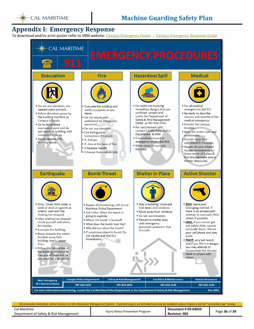
Machine Guarding Safety Plan
Electronically Controlled. Latest revision is in the Document Management System. A printed copy is uncontrolled and may be outdated unless it bears a red ink “controlled copy” stamp.
Cal Maritime Department of Safety & Risk Management
Injury Illness Prevention Program Document # 09-04020 Revision: 002 Page 36 of 39
Appendix I: Emergency Response To download and/or print poster refer to SRM website: Campus Emergency Poster , Campus Emergency Response Guide
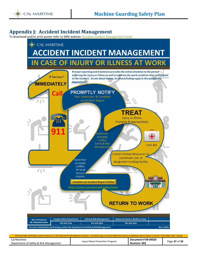
Machine Guarding Safety Plan
Electronically Controlled. Latest revision is in the Document Management System. A printed copy is uncontrolled and may be outdated unless it bears a red ink “controlled copy” stamp.
Cal Maritime Department of Safety & Risk Management
Injury Illness Prevention Program Document # 09-04020 Revision: 002 Page 37 of 39
Appendix J: Accident Incident Management To download and/or print poster refer to SRM website: Accident Incident Management Poster
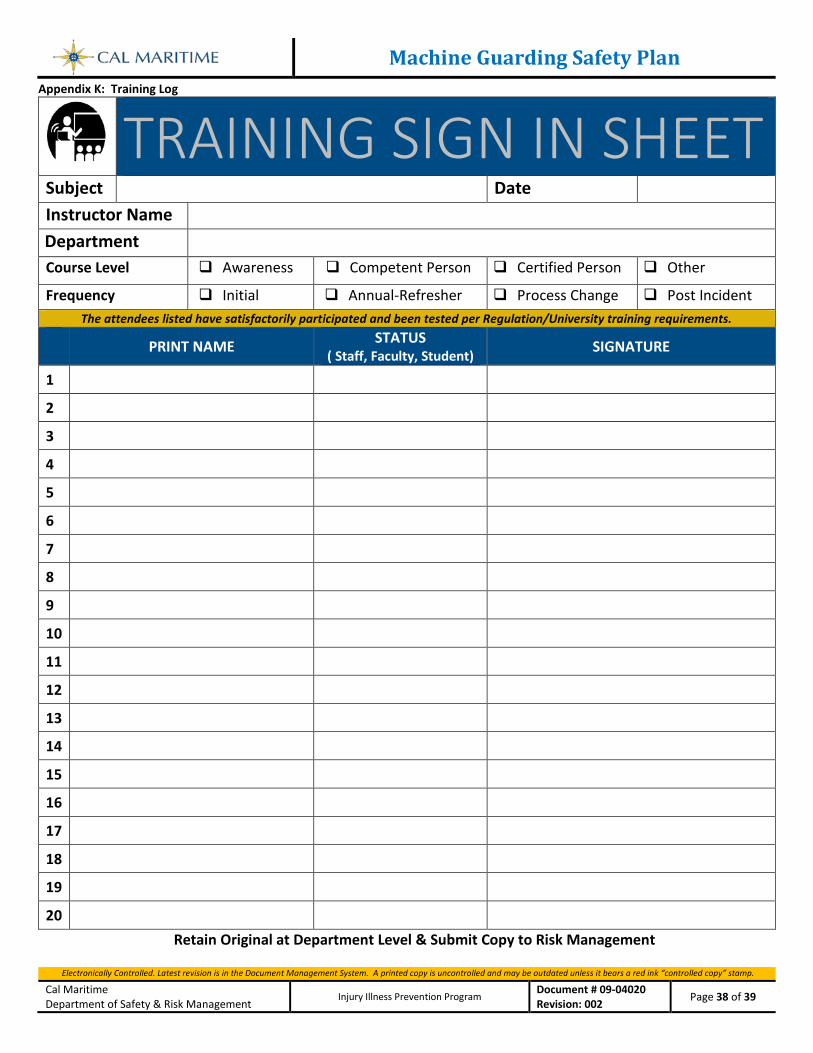
Machine Guarding Safety Plan
Electronically Controlled. Latest revision is in the Document Management System. A printed copy is uncontrolled and may be outdated unless it bears a red ink “controlled copy” stamp.
Cal Maritime Department of Safety & Risk Management
Injury Illness Prevention Program Document # 09-04020 Revision: 002 Page 38 of 39
Appendix K: Training Log
TRAINING SIGN IN SHEET
Subject Date Instructor Name Department Course Level Awareness Competent Person Certified Person Other
Frequency Initial Annual-Refresher Process Change Post Incident The attendees listed have satisfactorily participated and been tested per Regulation/University training requirements.
PRINT NAME STATUS ( Staff, Faculty, Student) SIGNATURE
1 2 3 4 5 6 7 8 9 10 11 12 13 14 15 16 17 18 19 20
Retain Original at Department Level & Submit Copy to Risk Management
Machine Guarding Safety Plan
Electronically Controlled. Latest revision is in the Document Management System. A printed copy is uncontrolled and may be outdated unless it bears a red ink “controlled copy” stamp.
Cal Maritime Department of Safety & Risk Management
Injury Illness Prevention Program Document # 09-04020 Revision: 002 Page 39 of 39