Embed Size (px)
DESCRIPTION
Machine Detector Interface Issues. Philip Burrows John Adams Institute Oxford University Thanks to: Tom Markiewicz. Outline. ‘Interaction hall’ considerations: push-pull configuration surface assembly ‘Beamline’ considerations: FF magnet package door opening/access - PowerPoint PPT Presentation
Citation preview
Philip Burrows SiD Meeting, Paris 11/02/081
Machine Detector Interface Issues
Philip BurrowsJohn Adams Institute
Oxford University
Thanks to: Tom Markiewicz
Philip Burrows SiD Meeting, Paris 11/02/082
Outline
• ‘Interaction hall’ considerations:push-pull configurationsurface assembly
• ‘Beamline’ considerations:FF magnet packagedoor opening/accesssupport of ‘R20’ modulebeampipe engineering
• Outlook
Philip Burrows SiD Meeting, Paris 11/02/083
Push-pull: SiD assumptions
• Having two detectors on beamline ‘permanently’, and sharing the luminosity, i.e. two IPs, is clearly the ideal solution for physics
• Luminosity delivery to two IPs, with fast switchover between IPs, is not possible
• Two detectors in push-pull mode will:
- save cost of one BDS
- increase likelihood of two detectors from start
- provide equal access to luminosity for both detectors
Philip Burrows SiD Meeting, Paris 11/02/084
SiD statement on technical Issues
• Push-pull can probably be engineered to work
- many technical issues will need to be solved
• Full access to offline detector is mandatory
• Best accomplished with self-shielding detectors
- self shielding is technically feasible
• Mechanisms for moving detector should not reduce acceptance
• Need to align ‘captured’ beamline components independent of overall detector position
Philip Burrows SiD Meeting, Paris 11/02/085
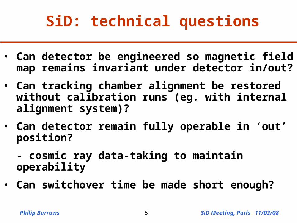
SiD: technical questions
• Can detector be engineered so magnetic field map remains invariant under detector in/out?
• Can tracking chamber alignment be restored without calibration runs (eg. with internal alignment system)?
• Can detector remain fully operable in ‘out’ position?
- cosmic ray data-taking to maintain operability
• Can switchover time be made short enough?
Philip Burrows SiD Meeting, Paris 11/02/086
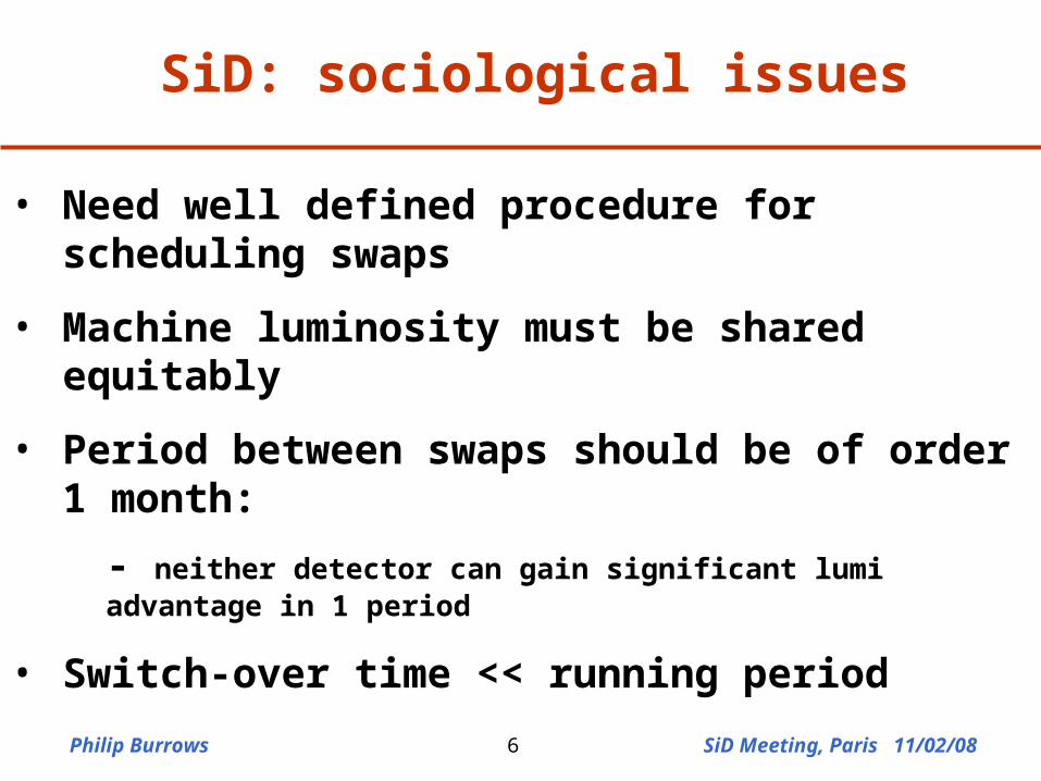
SiD: sociological issues
• Need well defined procedure for scheduling swaps
• Machine luminosity must be shared equitably
• Period between swaps should be of order 1 month:
- neither detector can gain significant lumi advantage in 1 period
• Switch-over time << running period
Philip Burrows SiD Meeting, Paris 11/02/087
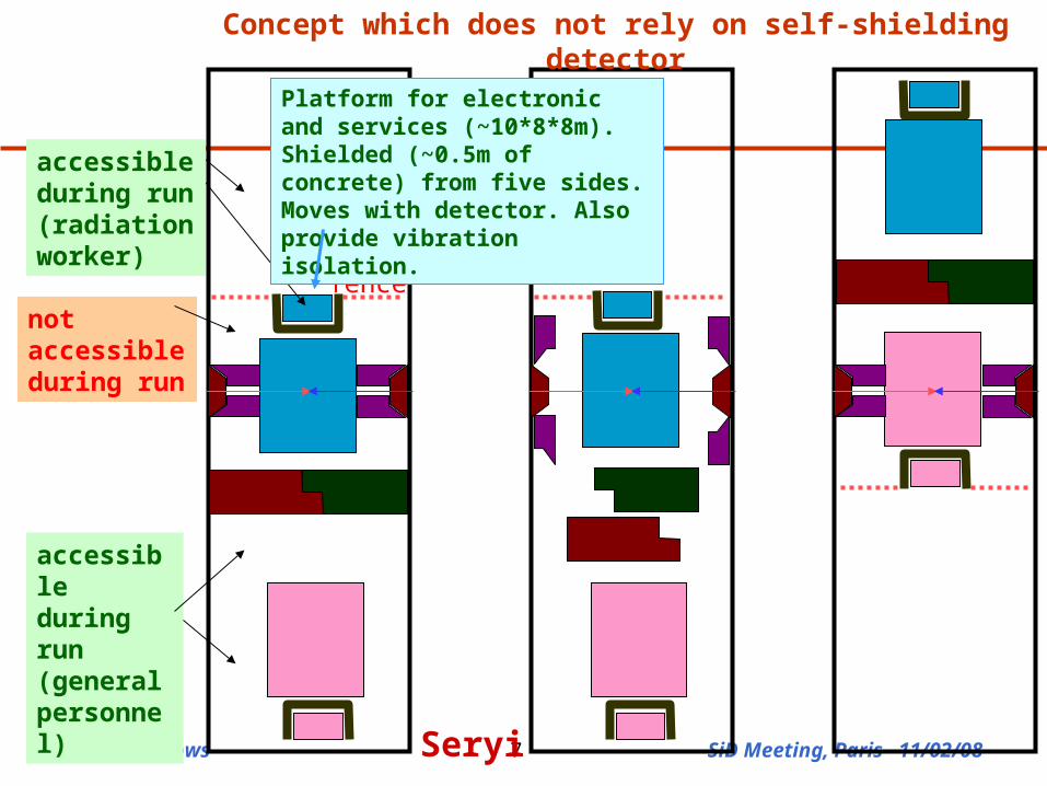
accessible during run (radiation worker)
accessible during run (general personnel)
not accessible during run
fence
Platform for electronic and services (~10*8*8m). Shielded (~0.5m of concrete) from five sides. Moves with detector. Also provide vibration isolation.
Concept which does not rely on self-shielding detector
Seryi
Philip Burrows SiD Meeting, Paris 11/02/088
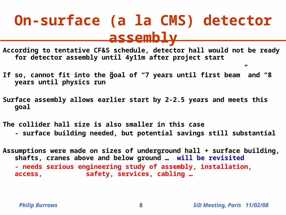
On-surface (a la CMS) detector assembly
According to tentative CF&S schedule, detector hall would not be ready for detector assembly until 4y11m after project start
If so, cannot fit into the goal of “7 years until first beam” and “8 years until physics run”
Surface assembly allows earlier start by 2-2.5 years and meets this goal
The collider hall size is also smaller in this case- surface building needed, but potential savings still substantial
Assumptions were made on sizes of underground hall + surface building, shafts, cranes above and below ground … will be revisited- needs serious engineering study of assembly, installation, access,
safety, services, cabling …
Philip Burrows SiD Meeting, Paris 11/02/089
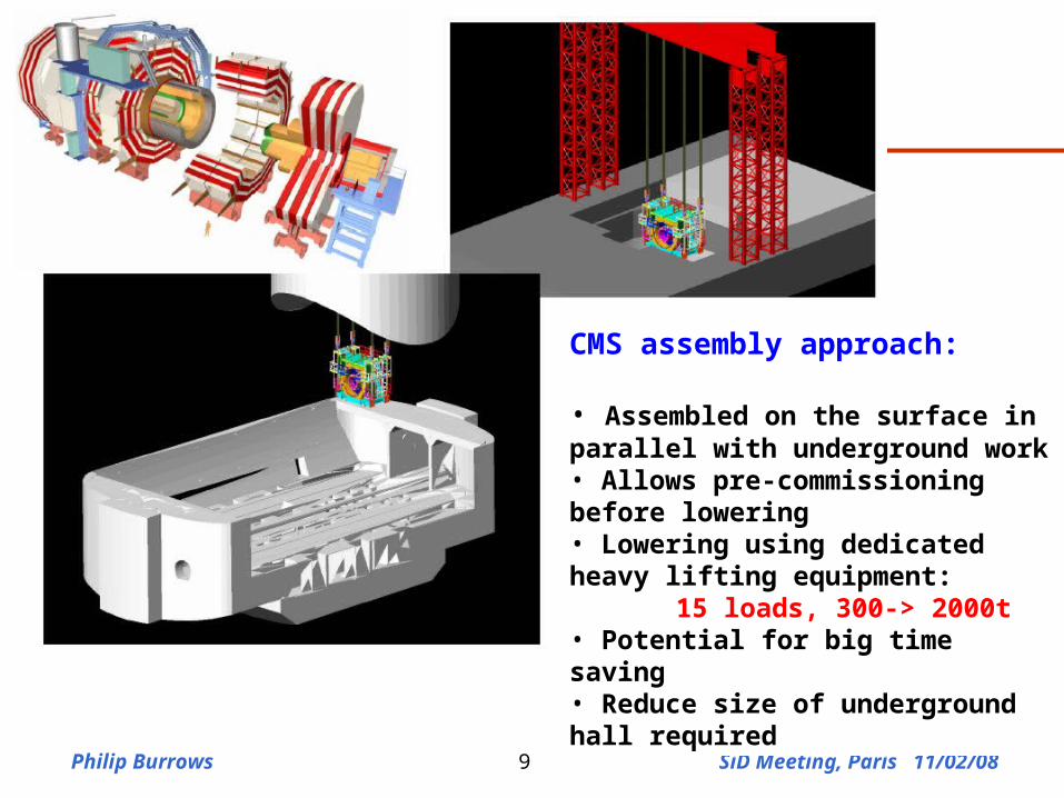
CMS assembly approach:
• Assembled on the surface in parallel with underground work• Allows pre-commissioning before lowering• Lowering using dedicated heavy lifting equipment:
15 loads, 300-> 2000t• Potential for big time saving• Reduce size of underground hall required
Philip Burrows SiD Meeting, Paris 11/02/0810
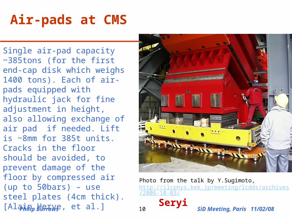
Air-pads at CMS
Photo from the talk by Y.Sugimoto, http://ilcphys.kek.jp/meeting/lcdds/archives/2006-10-03/
Single air-pad capacity ~385tons (for the first end-cap disk which weighs 1400 tons). Each of air-pads equipped with hydraulic jack for fine adjustment in height, also allowing exchange of air pad if needed. Lift is ~8mm for 385t units. Cracks in the floor should be avoided, to prevent damage of the floor by compressed air (up to 50bars) – use steel plates (4cm thick). [Alain Herve, et al.]
SiD also exploring ‘Hillman rollers’
Seryi
Philip Burrows SiD Meeting, Paris 11/02/0811
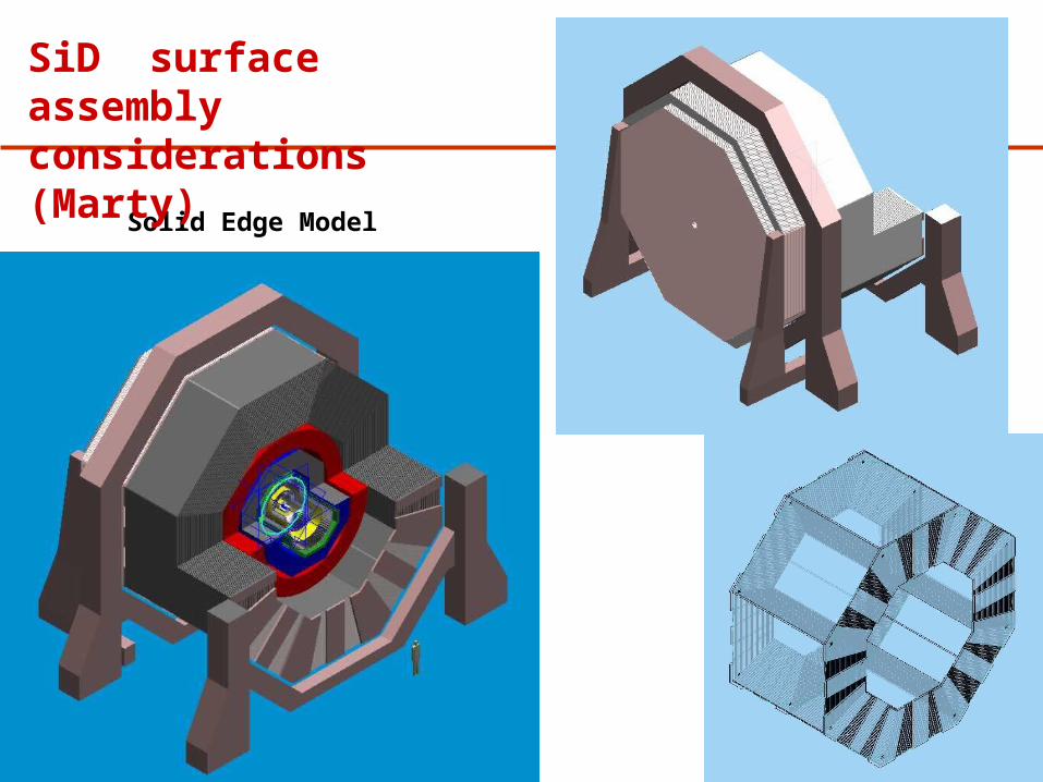
Solid Edge Model
SiD surface assembly considerations (Marty)
Philip Burrows SiD Meeting, Paris 11/02/0812
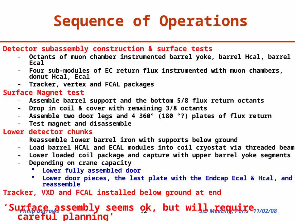
Sequence of Operations
Detector subassembly construction & surface tests– Octants of muon chamber instrumented barrel yoke, barrel Hcal, barrel Ecal– Four sub-modules of EC return flux instrumented with muon chambers, donut Hcal,
Ecal– Tracker, vertex and FCAL packages
Surface Magnet test– Assemble barrel support and the bottom 5/8 flux return octants– Drop in coil & cover with remaining 3/8 octants– Assemble two door legs and 4 360° (180 °?) plates of flux return– Test magnet and disassemble
Lower detector chunks– Reassemble lower barrel iron with supports below ground– Load barrel HCAL and ECAL modules into coil cryostat via threaded beam– Lower loaded coil package and capture with upper barrel yoke segments– Depending on crane capacity
Lower fully assembled door Lower door pieces, the last plate with the Endcap Ecal & Hcal, and reassemble
Tracker, VXD and FCAL installed below ground at end
‘Surface assembly seems ok, but will require careful planning’
Philip Burrows SiD Meeting, Paris 11/02/0813
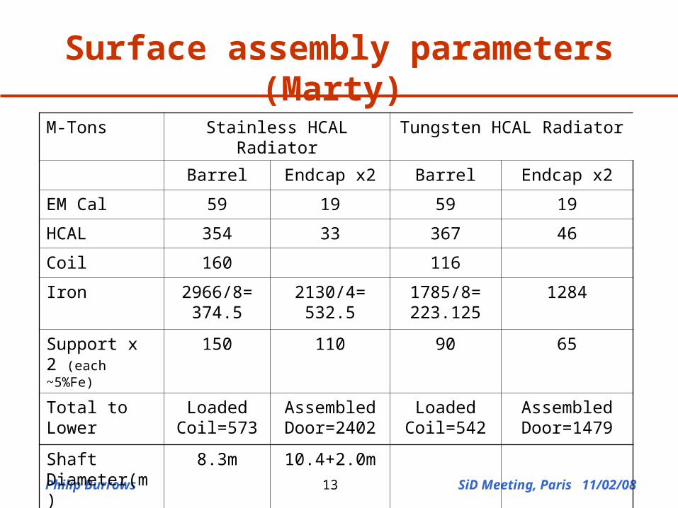
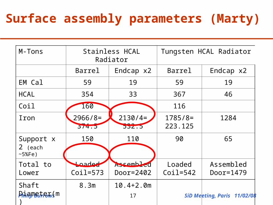
Surface assembly parameters (Marty)
M-Tons Stainless HCAL Radiator Tungsten HCAL Radiator
Barrel Endcap x2 Barrel Endcap x2
EM Cal 59 19 59 19
HCAL 354 33 367 46
Coil 160 116
Iron 2966/8= 374.5
2130/4= 532.5
1785/8= 223.125
1284
Support x 2 (each ~5%Fe)
150 110 90 65
Total to Lower Loaded Coil=573
Assembled Door=2402
Loaded Coil=542
Assembled Door=1479
Shaft Diameter(m)
8.3m 10.4+2.0m
Philip Burrows SiD Meeting, Paris 11/02/0814
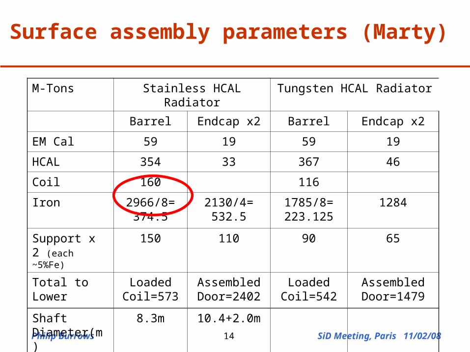
M-Tons Stainless HCAL Radiator Tungsten HCAL Radiator
Barrel Endcap x2 Barrel Endcap x2
EM Cal 59 19 59 19
HCAL 354 33 367 46
Coil 160 116
Iron 2966/8= 374.5
2130/4= 532.5
1785/8= 223.125
1284
Support x 2 (each ~5%Fe)
150 110 90 65
Total to Lower Loaded Coil=573
Assembled Door=2402
Loaded Coil=542
Assembled Door=1479
Shaft Diameter(m)
8.3m 10.4+2.0m
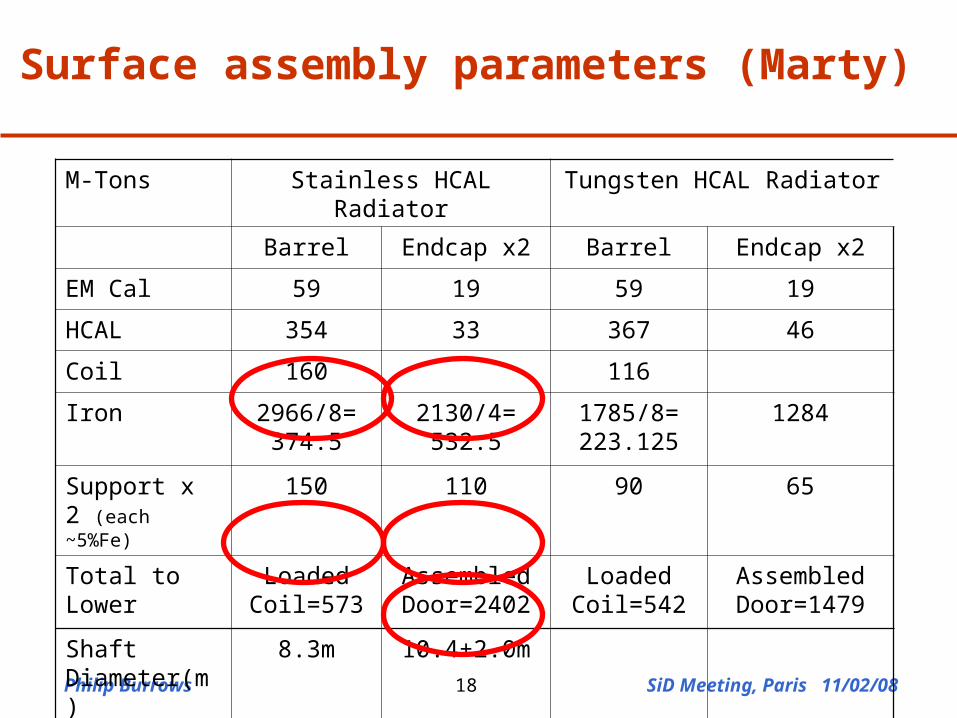
Surface assembly parameters (Marty)
Philip Burrows SiD Meeting, Paris 11/02/0815
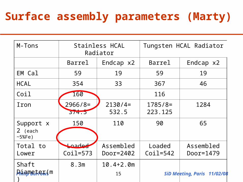
M-Tons Stainless HCAL Radiator Tungsten HCAL Radiator
Barrel Endcap x2 Barrel Endcap x2
EM Cal 59 19 59 19
HCAL 354 33 367 46
Coil 160 116
Iron 2966/8= 374.5
2130/4= 532.5
1785/8= 223.125
1284
Support x 2 (each ~5%Fe)
150 110 90 65
Total to Lower Loaded Coil=573
Assembled Door=2402
Loaded Coil=542
Assembled Door=1479
Shaft Diameter(m)
8.3m 10.4+2.0m
Surface assembly parameters (Marty)
Philip Burrows SiD Meeting, Paris 11/02/0816
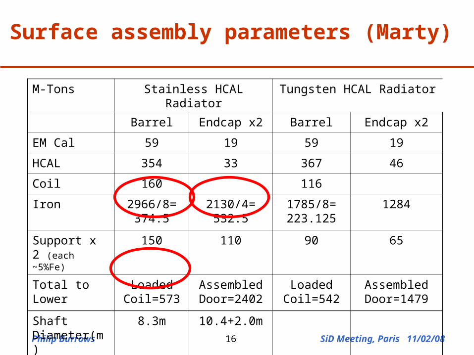
M-Tons Stainless HCAL Radiator Tungsten HCAL Radiator
Barrel Endcap x2 Barrel Endcap x2
EM Cal 59 19 59 19
HCAL 354 33 367 46
Coil 160 116
Iron 2966/8= 374.5
2130/4= 532.5
1785/8= 223.125
1284
Support x 2 (each ~5%Fe)
150 110 90 65
Total to Lower Loaded Coil=573
Assembled Door=2402
Loaded Coil=542
Assembled Door=1479
Shaft Diameter(m)
8.3m 10.4+2.0m
Surface assembly parameters (Marty)
Philip Burrows SiD Meeting, Paris 11/02/0817
M-Tons Stainless HCAL Radiator Tungsten HCAL Radiator
Barrel Endcap x2 Barrel Endcap x2
EM Cal 59 19 59 19
HCAL 354 33 367 46
Coil 160 116
Iron 2966/8= 374.5
2130/4= 532.5
1785/8= 223.125
1284
Support x 2 (each ~5%Fe)
150 110 90 65
Total to Lower Loaded Coil=573
Assembled Door=2402
Loaded Coil=542
Assembled Door=1479
Shaft Diameter(m)
8.3m 10.4+2.0m
Surface assembly parameters (Marty)
Philip Burrows SiD Meeting, Paris 11/02/0818
M-Tons Stainless HCAL Radiator Tungsten HCAL Radiator
Barrel Endcap x2 Barrel Endcap x2
EM Cal 59 19 59 19
HCAL 354 33 367 46
Coil 160 116
Iron 2966/8= 374.5
2130/4= 532.5
1785/8= 223.125
1284
Support x 2 (each ~5%Fe)
150 110 90 65
Total to Lower Loaded Coil=573
Assembled Door=2402
Loaded Coil=542
Assembled Door=1479
Shaft Diameter(m)
8.3m 10.4+2.0m
Surface assembly parameters (Marty)
Philip Burrows SiD Meeting, Paris 11/02/0819
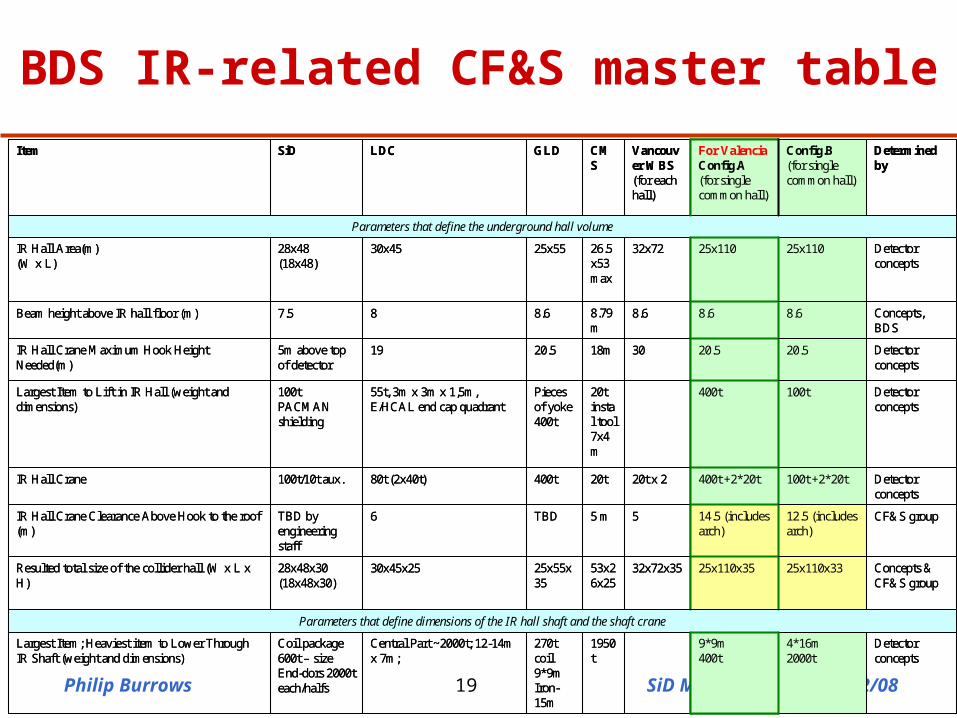
Detector concepts
4*16m2000t
9*9m400t
1950t
270t coil9*9m Iron-15m
Central Part ~2000t; 12-14m x 7m;
Coil package 600t – sizeEnd-dors 2000t each/halfs
Largest Item; Heaviest item to Lower Through IR Shaft (weight and dimensions)
Parameters that define dimensions of the IR hall shaft and the shaft crane
Concepts & CF&S group
25x110x3325x110x3532x72x3553x26x25
25x55x35
30x45x2528x48x30(18x48x30)
Resulted total size of the collider hall (W x L x H)
CF&S group12.5 (includes arch)
14.5 (includes arch)
55 mTBD6TBD by engineering staff
IR Hall Crane Clearance Above Hook to the roof (m)
Detector concepts
100t +2*20t400t +2*20t20t x 220t400t80t (2x40t)100t/10t aux.IR Hall Crane
Detector concepts
100t400t20tinstal tool7x4m
Pieces of yoke400t
55t, 3m x 3m x 1,5m, E/HCAL end cap quadrant
100tPACMAN shielding
Largest Item to Lift in IR Hall (weight and dimensions)
Detector concepts
20.520.53018m20.5195m above top of detector
IR Hall Crane Maximum Hook Height Needed(m)
Concepts, BDS
8.68.68.68.79m
8.687.5Beam height above IR hall floor (m)
Detector concepts
25x11025x11032x7226.5x53max
25x5530x4528x48(18x48)
IR Hall Area(m) (W x L)
Parameters that define the underground hall volume
Determined by
Config.B(for single common hall)
For ValenciaConfig.A(for single common hall)
Vancouver WBS(for each hall)
CMS
GLDLDCSiDItem
Detector concepts
4*16m2000t
9*9m400t
1950t
270t coil9*9m Iron-15m
Central Part ~2000t; 12-14m x 7m;
Coil package 600t – sizeEnd-dors 2000t each/halfs
Largest Item; Heaviest item to Lower Through IR Shaft (weight and dimensions)
Parameters that define dimensions of the IR hall shaft and the shaft crane
Concepts & CF&S group
25x110x3325x110x3532x72x3553x26x25
25x55x35
30x45x2528x48x30(18x48x30)
Resulted total size of the collider hall (W x L x H)
CF&S group12.5 (includes arch)
14.5 (includes arch)
55 mTBD6TBD by engineering staff
IR Hall Crane Clearance Above Hook to the roof (m)
Detector concepts
100t +2*20t400t +2*20t20t x 220t400t80t (2x40t)100t/10t aux.IR Hall Crane
Detector concepts
100t400t20tinstal tool7x4m
Pieces of yoke400t
55t, 3m x 3m x 1,5m, E/HCAL end cap quadrant
100tPACMAN shielding
Largest Item to Lift in IR Hall (weight and dimensions)
Detector concepts
20.520.53018m20.5195m above top of detector
IR Hall Crane Maximum Hook Height Needed(m)
Concepts, BDS
8.68.68.68.79m
8.687.5Beam height above IR hall floor (m)
Detector concepts
25x11025x11032x7226.5x53max
25x5530x4528x48(18x48)
IR Hall Area(m) (W x L)
Parameters that define the underground hall volume
Determined by
Config.B(for single common hall)
For ValenciaConfig.A(for single common hall)
Vancouver WBS(for each hall)
CMS
GLDLDCSiDItem
BDS IR-related CF&S master table
Philip Burrows SiD Meeting, Paris 11/02/0820-0.5
-0.4
-0.3
-0.2
-0.1
0
0.1
0.2
0.3
0.4
0.5
0 2 4 6 8 10 12 14 16
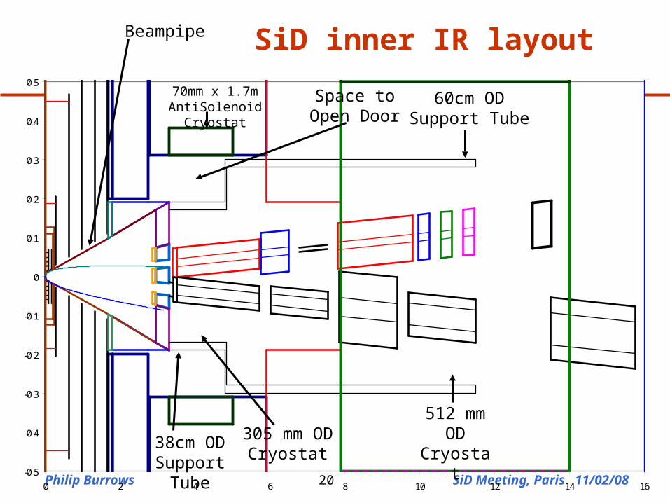
SiD inner IR layout
305 mm OD Cryostat
512 mm OD
Cryostat
70mm x 1.7m AntiSolenoid Cryostat
60cm OD Support Tube
38cm OD Support Tube
Space to Open Door
Beampipe
Philip Burrows SiD Meeting, Paris 11/02/0821
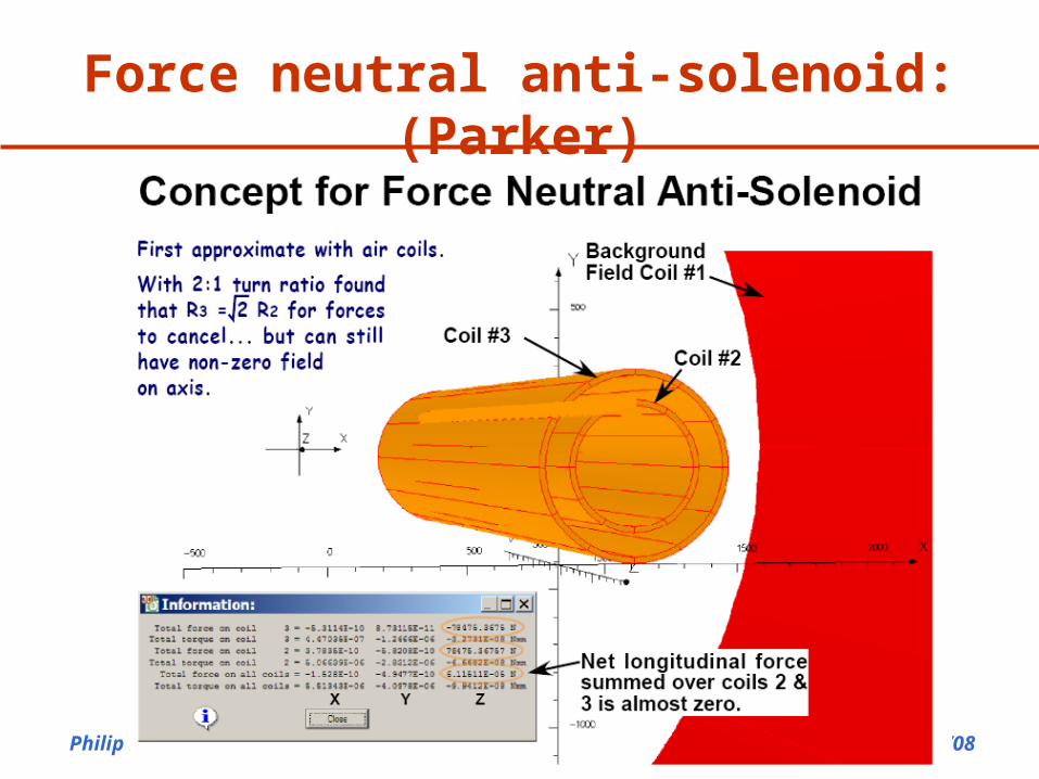
Force neutral anti-solenoid: (Parker)
Philip Burrows SiD Meeting, Paris 11/02/0822
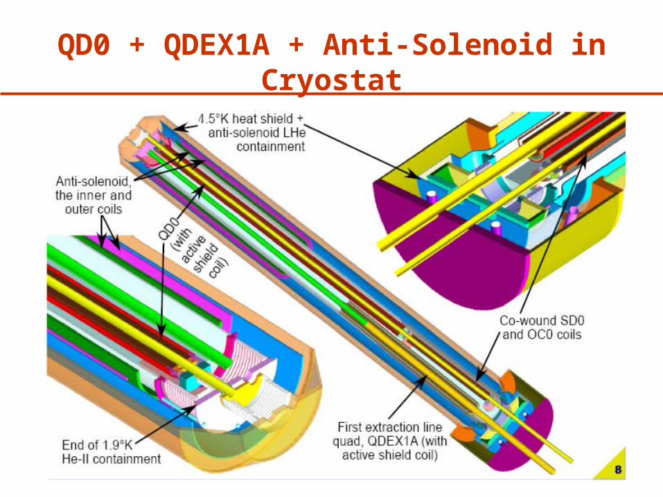
QD0 + QDEX1A + Anti-Solenoid in Cryostat
Philip Burrows SiD Meeting, Paris 11/02/0823
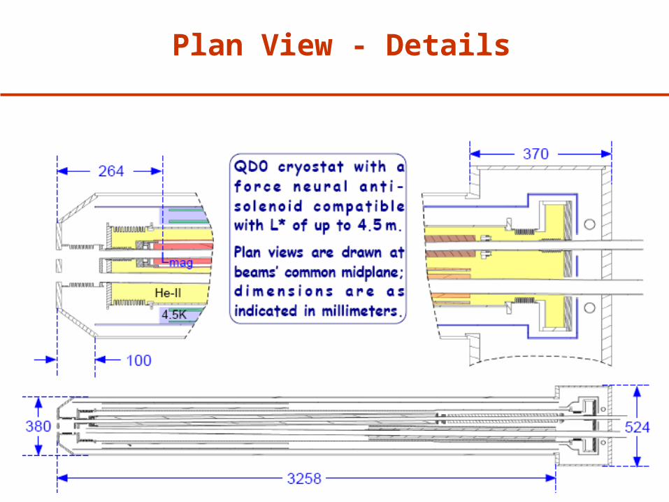
Plan View - Details
Philip Burrows SiD Meeting, Paris 11/02/0824
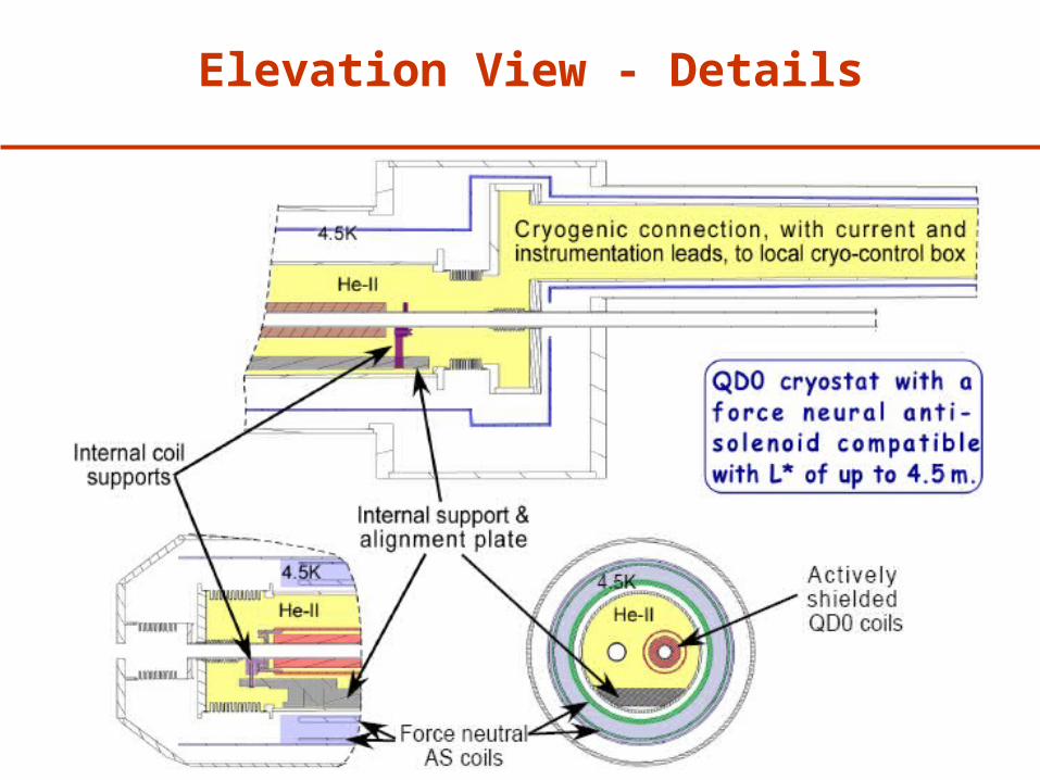
Elevation View - Details
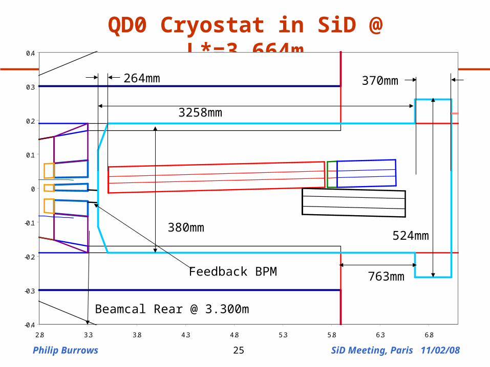
Philip Burrows SiD Meeting, Paris 11/02/0825
QD0 Cryostat in SiD @ L*=3.664m
-0.4
-0.3
-0.2
-0.1
0
0.1
0.2
0.3
0.4
2.8 3.3 3.8 4.3 4.8 5.3 5.8 6.3 6.8
380mm
3258mm
264mm 370mm
524mm
763mm
Beamcal Rear @ 3.300m
Feedback BPM
Philip Burrows SiD Meeting, Paris 11/02/0826
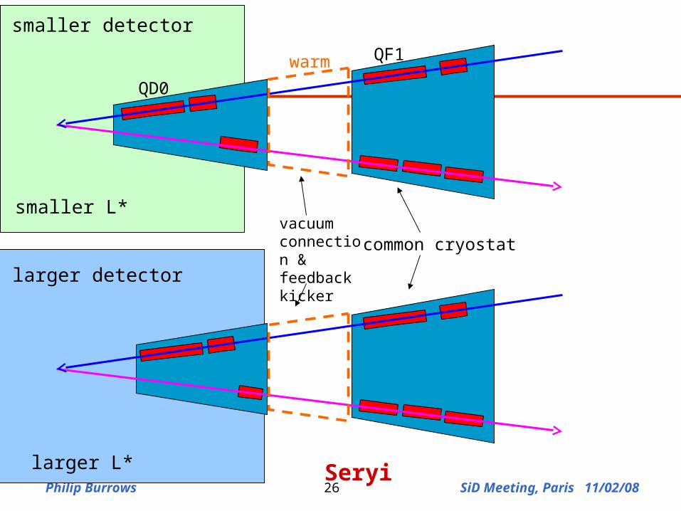
warm
smaller detector
larger detector
smaller L*
larger L*
common cryostat
QD0
QF1
vacuum connection & feedback kicker
Seryi
Philip Burrows SiD Meeting, Paris 11/02/0827
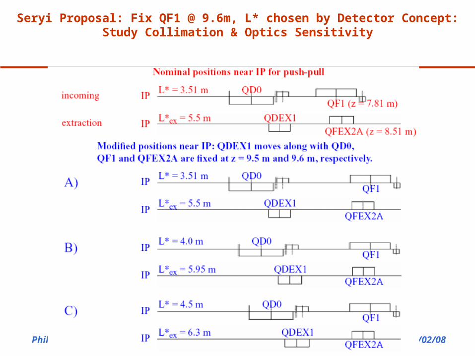
Seryi Proposal: Fix QF1 @ 9.6m, L* chosen by Detector Concept: Study Collimation & Optics Sensitivity
Philip Burrows SiD Meeting, Paris 11/02/0828-0.5
-0.4
-0.3
-0.2
-0.1
0
0.1
0.2
0.3
0.4
0.5
0 2 4 6 8 10 12 14 16
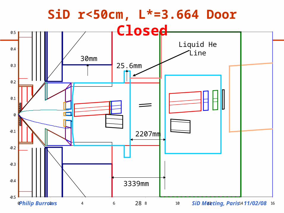
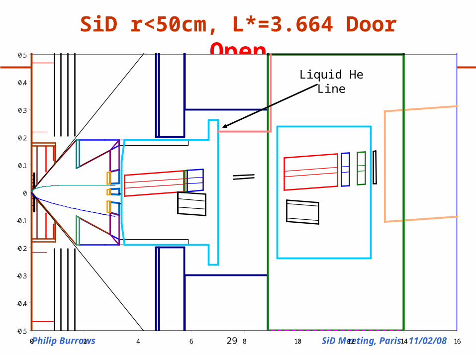
3339mm
2207mm
Liquid He Line
25.6mm30mm
SiD r<50cm, L*=3.664 Door Closed
Philip Burrows SiD Meeting, Paris 11/02/0829
SiD r<50cm, L*=3.664 Door Open
-0.5
-0.4
-0.3
-0.2
-0.1
0
0.1
0.2
0.3
0.4
0.5
0 2 4 6 8 10 12 14 16
Liquid He Line
Philip Burrows SiD Meeting, Paris 11/02/0830
-8
-6
-4
-2
0
2
4
6
8
0 1 2 3 4 5 6 7 8 9 10
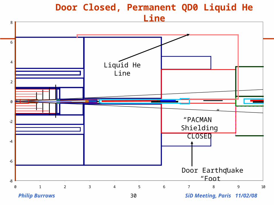
Door Closed, Permanent QD0 Liquid He Line
Liquid He Line
“PACMAN” ShieldingCLOSED
Door Earthquake “Foot”
Philip Burrows SiD Meeting, Paris 11/02/0831
-8
-6
-4
-2
0
2
4
6
8
0 1 2 3 4 5 6 7 8 9 10
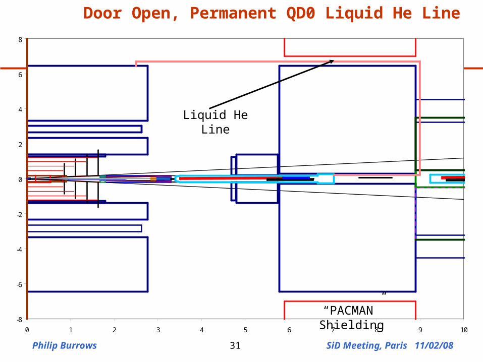
Door Open, Permanent QD0 Liquid He Line
Liquid He Line
“PACMAN” Shielding
Philip Burrows SiD Meeting, Paris 11/02/0832
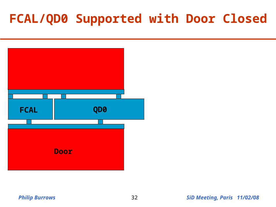
Door
QD0FCAL
FCAL/QD0 Supported with Door Closed
Philip Burrows SiD Meeting, Paris 11/02/0833
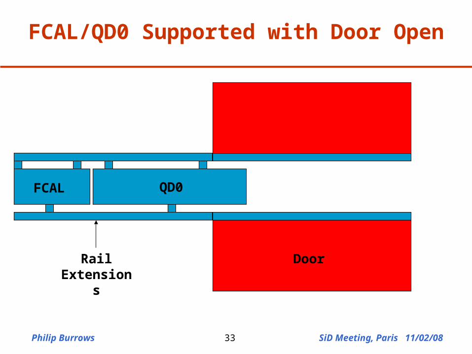
FCAL QD0
DoorRail Extensions
FCAL/QD0 Supported with Door Open
Philip Burrows SiD Meeting, Paris 11/02/0834
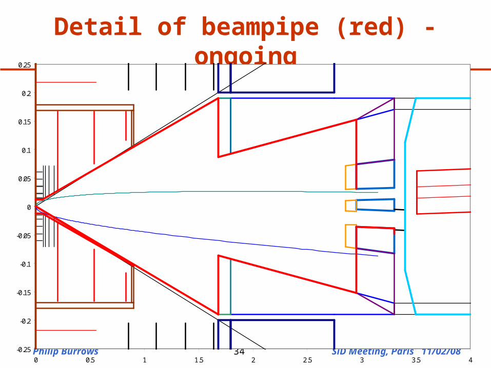
Detail of beampipe (red) - ongoing
-0.25
-0.2
-0.15
-0.1
-0.05
0
0.05
0.1
0.15
0.2
0.25
0 0.5 1 1.5 2 2.5 3 3.5 4
Philip Burrows SiD Meeting, Paris 11/02/0835
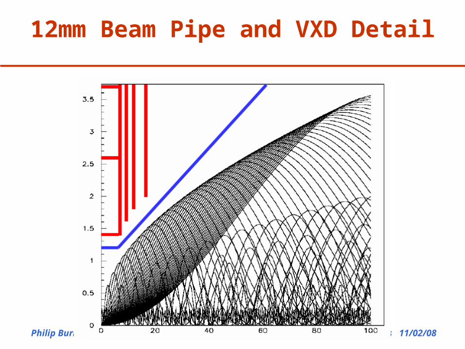
12mm Beam Pipe and VXD Detail
Philip Burrows SiD Meeting, Paris 11/02/0836
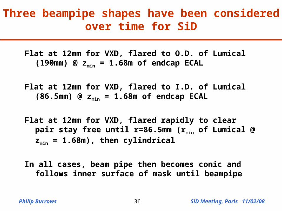
Three beampipe shapes have been considered over time for SiD
Flat at 12mm for VXD, flared to O.D. of Lumical (190mm) @ zmin = 1.68m of endcap ECAL
Flat at 12mm for VXD, flared to I.D. of Lumical (86.5mm) @ zmin = 1.68m of endcap ECAL
Flat at 12mm for VXD, flared rapidly to clear pair stay free until r=86.5mm (rmin of Lumical @ zmin = 1.68m), then cylindrical
In all cases, beam pipe then becomes conic and follows inner surface of mask until beampipe
Philip Burrows SiD Meeting, Paris 11/02/0837
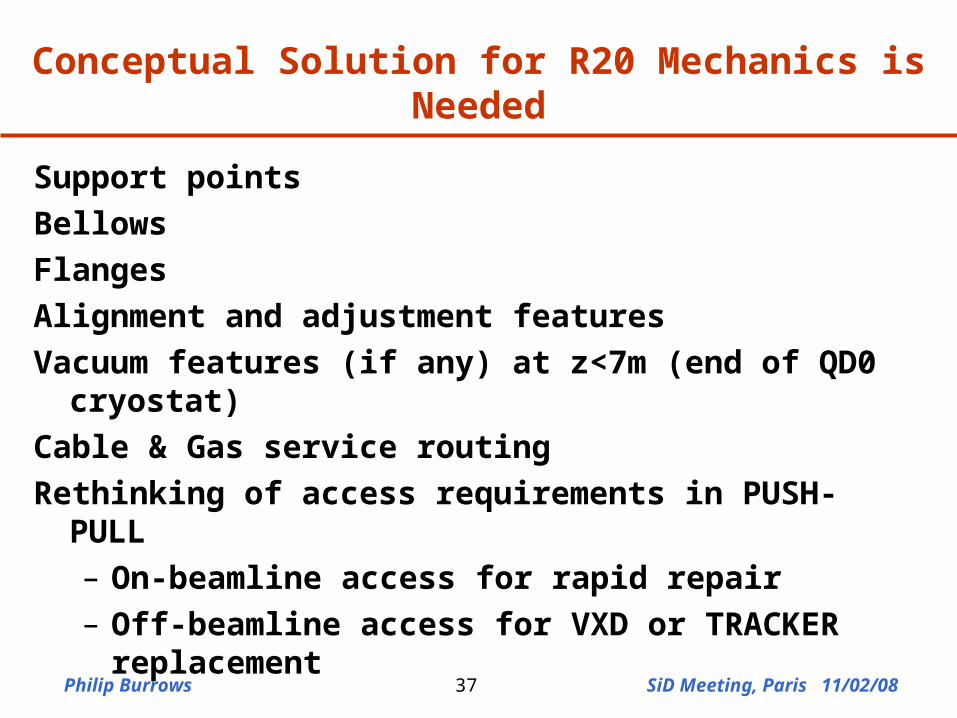
Conceptual Solution for R20 Mechanics is Needed
Support points
Bellows
Flanges
Alignment and adjustment features
Vacuum features (if any) at z<7m (end of QD0 cryostat)
Cable & Gas service routing
Rethinking of access requirements in PUSH-PULL– On-beamline access for rapid repair– Off-beamline access for VXD or TRACKER
replacement
Philip Burrows SiD Meeting, Paris 11/02/0838
Summary
• GDE RDR BDS baseline comprises a conceptual model of
MDI based on push-pull + surface assembly
• MDI complex area requiring careful design
• Self-consistent conceptual scheme for SiD MDI has been
developed
• IR engineering workshop September 2007
• Engineering, engineering, engineering!
‘macroscopic’: buildings, shafts, caverns, cranes …
‘microscopic’: beampipes, valves, bellows, flanges …