Embed Size (px)
Citation preview
Machine Design 1. Design of Joints: Cotters Keys Splines Welded joints Threaded fasteners Joints formed by interference fits
2. Design of friction drives Couplings Clutches Introduction Friction clutches Torque transmitting capacity Uniform pressure theory Uniform wear theory Multi-disk clutches Cone clutches Centrifugal clutches Friction materials for clutches Belt and Chain drives Length of the belt Belt tension
Centrifugal tension Condition for maximum power Selection of V-belt drive
Initial tension in the belt Chain drive Rope drive
Power screw Types of power screw Self locking screw Efficiency of screw Collar friction
3. Design of power transmission system Spur gear Classification of Gears
Mitres gear Pitch point Pressure angle Backlash Minimum Number of Teeth Forms of teeth Cycloidal teeth Involute teeth Contact ratio Interference Face Width Beam Strength of Gear Tooth Wear Strength of Gear Tooth Gear Lubrication Simple Gear train Compound gear train Reverted gear train Epicyclic gear train
Helical Gears Terminology of Helical Gears Virtual Number of Teeth Bevel Gears Worm Gears Worm Gears 600 Friction in Worm Gears 6JJ Selection of Materials 618 Strength Rating of Worm Gears 618 Wear Rating of Worm Gears 622 Thermal Considerations 6
4. Design of bearings Rolling Contact Bearings Types of Rolling Contact Bearings 417 Dynamic Load Carrying Capacity 422 Equivalent Bearing Load 423 Load-life Relationship 423 Selection of Taper Roller Bearings 437 Lubrication of Rolling Contact Bearings 453 Sliding Contact Bearings Basic Modes of Lubrication 456 Hydrostatic Step Bearing 464 Energy Losses in Hydrostatic Bearing 466 Temperature Rise 483 Bearing Materials 495 Lubricating Oils 497 Greases 502 Comparison of Rolling and Sliding Contact bearings 503
5. Fluctuating Load Consideration for Design Stress Concentration 117 Fluctuating Stresses 127 Endurance Limit 128 Notch Sensitivity 130 Soderberg and Goodman Diagrams 146 Gyroscopic motion
6. Miscellaneous
1. Design of Joint Objective Questions (IES, IAS, GATE)
Cotters 1. Match List I with List II and select the correct answer using the code given below the Lists: List I List II
(Application) (Joint) A. Boiler shell 1. Cotter joint B. Marine shaft coupling 2. Knuckle joint C. Crosshead and piston road 3. Riveted joint D. Automobile gear box 4. Splines (gears to shaft) 5. Bolted Joint
Code: [IES 2007] A B C D A B C D
(a) 1 4 2 5 (b) 3 5 1 4 (c) 1 5 2 4 (d) 3 4 1 5 1. Ans. (b) 2. Match List-I (Parts to be joined) with List-II (Type of Joint) and select the correct answer using the code given below: [IES-2006] List-I List -II A. Two rods having relative axial 1. Pin Joint motion B. Strap end of the connecting rod 2. Knuckle Joint C. Piston rod and cross head 3. Gib and Cotter Joint D. Links of four-bar chain 4. Cotter Joint A B C D A B C D (a) 1 3 4 2 (b) 2 4 3 1 (c) 1 4 3 2 (d) 2 3 4 1 2. Ans. (d) 3. Match List I with List II and select the correct answer. [IES-1994]
List I (Types of joints) List II (An element of the joint) A. Riveted joint 1. Pin B. Welded joint 2. Strap C. Bolted joint 3. Lock washer D. Knuckle joint 4. Fillet Codes: A B C D A B C D (a) 4 3 2 1 (b) 2 3 4 1 (c) 2 4 3 1 (d) 2 4 1 3 3. Ans. (c) 4. In a gib and cotter joint, the gib and cotter are subjected to [IES-2006] (a) single shear only (b) double shear only (c) single shear and crushing (d) double shear and crushing 4. Ans. (b) 5. Match List I (Items in joints) with List II (Type of failure) and select the correct answer using the codes given below the Lists: [IES-2004] List I List II
A. Bolts in bolted joints of engine cylinder cover plate 1. Double transverse shear B. Cotters in cotter joint 2. Torsional shear C Rivets in lap joints 3 Single transverse shear D. Bolts holding two flanges in a flange coupling 4. Tension A B C D A B C D (a) 4 1 3 2 (b) 4 2 3 1 (c) 3 1 4 2 (d) 3 2 4 1 5. Ans. (a) 6. In a cotter joint, the width of the cotter at the centre is 50 mm and its thickness is 12 mm. The load acting on the cotter is 60 kN. What is the shearing stress developed in the cotter? [IES-2004] (a) 120 N/mm2 (b) 100 N/mm2 (c) 75 N/mm2 (d) 50 N/mm2
6. Ans. (d) It is a case of double shear.
Shear stress3
2Load 60 10 50N / mm2 Area 2 50 12
×= = =
× × ×
7. The spigot of a cotter joint has a diameter D and carries a slot for cotter. The permissible crushing stress is x times the permissible tensile stress for the material of spigot where x > 1. The joint carries an axial load P. Which one of the following equations will give the diameter of the spigot? [IES-2001]
(a) 12
t
P xDxπσ−
= (b) 12
t
P xDxπσ+
= (c) 2 1
t
P xDxπ σ+
= (d) 2 1
t
PD xπσ
= +
7. Ans. (b) 8. Match List-l (Machine element) with List-II (Cause of failure) and select the correct answer using the codes given below the lists: [IES-1998] List-I List-II A. Axle 1. Shear stress B. Cotter 2. Tensile/compressive stress C. Connecting rod 3. Wear D. Journal bearing 4. Bending stress Code: A B C D A B C D (a) 1 4 2 3 (b) 4 1 2 3 (c) 4 1 3 2 (d) 1 4 3 2 8. Ans. (a) 9. The piston rod and the crosshead in a steam engine are usually connected by means of (a) Cotter joint (b) Knuckle joint (c) Ball joint (d) Universal joint [IES-2003] 9. Ans. (a) 10. A cotter joint is used when no relative motion is permitted between the rods joined by the cotter. It is capable of transmitting [IES-2002] (a) twisting moment (b) an axial tensile as well as compressive load (c) the bending moment (d) only compressive axial load 10. Ans. (b) 11. Match List I with List II and select the correct answer using the codes given below the lists:
List I List II [IES-1995] (Different types of detachable joints) (Specific use of these detachable joints) A. Cotter joint 1. Tie rod of a wall crane
B. Knuckle joint 2. Suspension bridges C. Suspension link joint 3. Diagonal stays in boiler D. Turn buckle (adjustable joint) 4. Cross-head of a steam engine. Codes: A B C D A B C D (a) 4 2 3 1 (b) 4 3 2 1 (c) 3 2 1 4 (d) 2 1 4 3 11. Ans. (b) 12. Match List I with List II and select the correct answer using the codes given below the lists: List I (Type of joint) List II (Mode of jointing members) [IES-1993] A. Cotter joint 1. Connects two rods or bars permitting small amount of flexibility B. Knuckle joint 2. Rigidly connects two members C. Turn buckle 3. Connects two rods having threaded ends D. Riveted joint 4. Permanent fluid-tight joint between two flat pieces
5. Connects two shafts and transmits torque Codes: A B C D A B C D (a) 5 1 3 2 (b) 2 1 3 4 (c) 5 3 2 4 (d) 2 3 1 4 12. Ans. (b) 13. Assertion (A): When the coupler of a turn buckle is turned in one direction both the connecting rods either move closer or move away from each other depending upon the direction of rotation of the coupler. [IES-1996] Reason (R): A turn buckle is used to connect two round rods subjected to tensile loading and requiring subsequent adjustment for tightening or loosening. 13. Ans. (a)
Keys 14. In the assembly design of shaft, pulley and key, the weakest member is (a) pulley (b) key (c) shaft (d) none [IES-1998] 14. Ans. (b) 15. Match List-I (Type of keys) with List-II (Characteristic) and select the correct answer using the codes given below the Lists: [IES-1997] List-I List-II A. Woodruff key 1. Loose fitting, light duty B. Kennedy key 2. Heavy duty C. Feather key 3. Self-aligning D. Flat key 4. Normal industrial use Code: A B C D A B C D (a) 2 3 1 4 (b) 3 2 1 4 (c) 2 3 4 1 (d) 3 2 4 1 15. Ans. (d) 16. A spur gear transmitting power is connected to the shaft with a key of rectangular section. The type (s) of stresses developed in the key is fare. [IES-1995] (a) shear stress alone (b) bearing stress alone (c) both shear and bearing stresses (d) shearing, bearing and bending stresses. 16. Ans. (c) Key develops both shear and bearing stresses. 17. Assertion (A): The effect of keyways on a shaft is to reduce its load carrying capacity and to increase its torsional rigidity. [IES-1994]
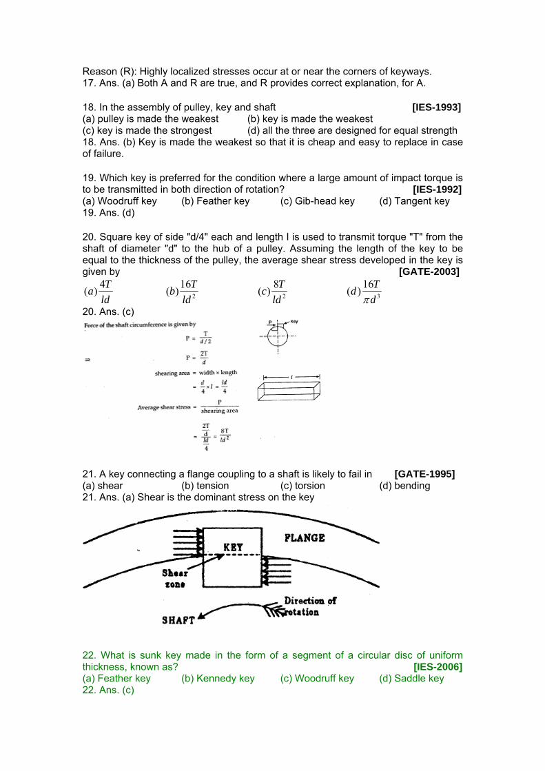
Reason (R): Highly localized stresses occur at or near the corners of keyways. 17. Ans. (a) Both A and R are true, and R provides correct explanation, for A. 18. In the assembly of pulley, key and shaft [IES-1993] (a) pulley is made the weakest (b) key is made the weakest (c) key is made the strongest (d) all the three are designed for equal strength 18. Ans. (b) Key is made the weakest so that it is cheap and easy to replace in case of failure. 19. Which key is preferred for the condition where a large amount of impact torque is to be transmitted in both direction of rotation? [IES-1992] (a) Woodruff key (b) Feather key (c) Gib-head key (d) Tangent key 19. Ans. (d) 20. Square key of side "d/4" each and length I is used to transmit torque "T" from the shaft of diameter "d" to the hub of a pulley. Assuming the length of the key to be equal to the thickness of the pulley, the average shear stress developed in the key is given by [GATE-2003]
2 2 3
4 16 8 16( ) ( ) ( ) ( )T T T Ta b c dld ld ld dπ
20. Ans. (c)
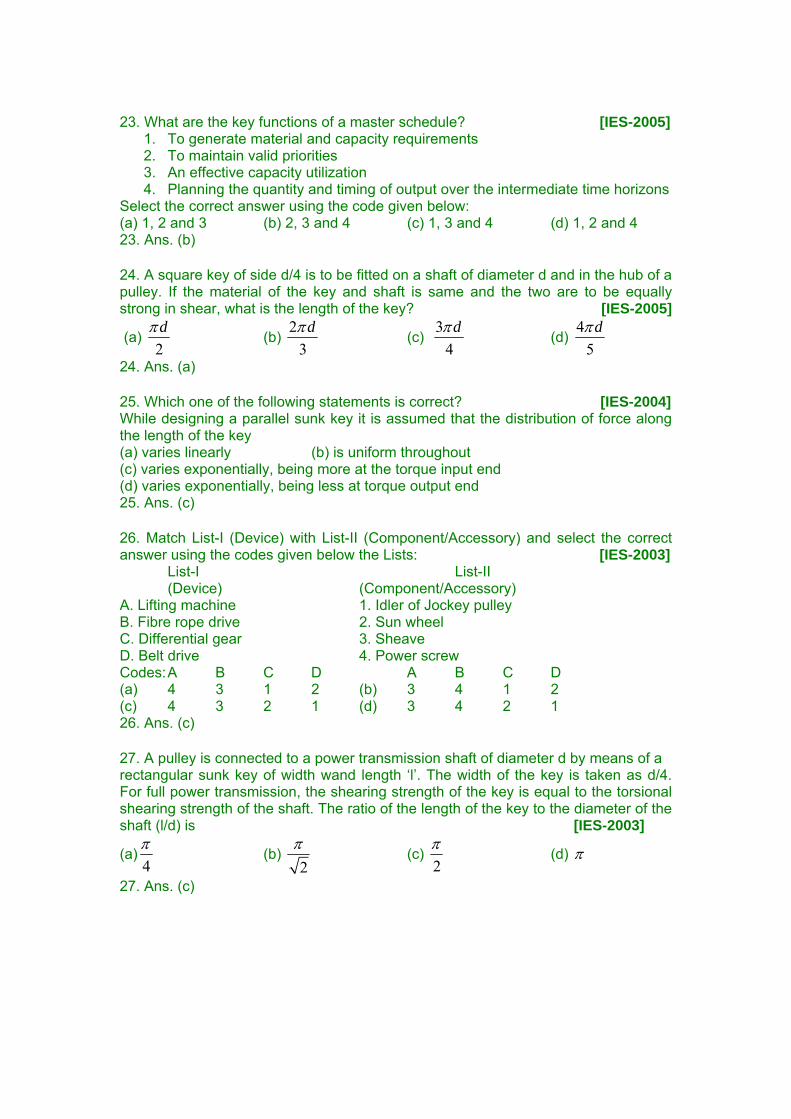
21. A key connecting a flange coupling to a shaft is likely to fail in [GATE-1995] (a) shear (b) tension (c) torsion (d) bending 21. Ans. (a) Shear is the dominant stress on the key
22. What is sunk key made in the form of a segment of a circular disc of uniform thickness, known as? [IES-2006] (a) Feather key (b) Kennedy key (c) Woodruff key (d) Saddle key 22. Ans. (c)
23. What are the key functions of a master schedule? [IES-2005]
1. To generate material and capacity requirements 2. To maintain valid priorities 3. An effective capacity utilization 4. Planning the quantity and timing of output over the intermediate time horizons
Select the correct answer using the code given below: (a) 1, 2 and 3 (b) 2, 3 and 4 (c) 1, 3 and 4 (d) 1, 2 and 4 23. Ans. (b) 24. A square key of side d/4 is to be fitted on a shaft of diameter d and in the hub of a pulley. If the material of the key and shaft is same and the two are to be equally strong in shear, what is the length of the key? [IES-2005]
(a) 2dπ
(b) 2
3dπ
(c) 3
4dπ
(d) 4
5dπ
24. Ans. (a) 25. Which one of the following statements is correct? [IES-2004] While designing a parallel sunk key it is assumed that the distribution of force along the length of the key (a) varies linearly (b) is uniform throughout (c) varies exponentially, being more at the torque input end (d) varies exponentially, being less at torque output end 25. Ans. (c) 26. Match List-I (Device) with List-II (Component/Accessory) and select the correct answer using the codes given below the Lists: [IES-2003] List-I List-II (Device) (Component/Accessory) A. Lifting machine 1. Idler of Jockey pulley B. Fibre rope drive 2. Sun wheel C. Differential gear 3. Sheave D. Belt drive 4. Power screw Codes: A B C D A B C D (a) 4 3 1 2 (b) 3 4 1 2 (c) 4 3 2 1 (d) 3 4 2 1 26. Ans. (c) 27. A pulley is connected to a power transmission shaft of diameter d by means of a rectangular sunk key of width wand length ‘l’. The width of the key is taken as d/4. For full power transmission, the shearing strength of the key is equal to the torsional shearing strength of the shaft. The ratio of the length of the key to the diameter of the shaft (l/d) is [IES-2003]
(a)4π
(b) 2π
(c) 2π
(d) π
27. Ans. (c)
4
3
3
Shearingstrength of key: . .4
Torque(T) = . . . .2 4 2
Torsionalshearing,
232
16For same strength
. . .4 2 16
2
dF l
d d dF l
Tdd
or T d
d dl d
lord
τ
τ
τπ
τπ
ττ π
π
⎛ ⎞= ⎜ ⎟⎝ ⎠
⎛ ⎞= ⎜ ⎟⎝ ⎠
=
= ×
⎛ ⎞ = ×⎜ ⎟⎝ ⎠
=
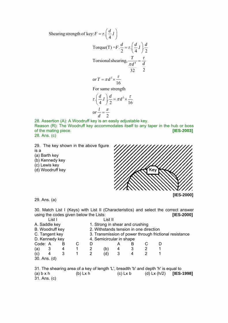
28. Assertion (A): A Woodruff key is an easily adjustable key. Reason (R): The Woodruff key accommodates itself to any taper in the hub or boss of the mating piece. [IES-2003] 28. Ans. (c) 29. The key shown in the above figure is a (a) Barth key (b) Kennedy key (c) Lewis key (d) Woodruff key
[IES-2000]
29. Ans. (a) 30. Match List I (Keys) with List II (Characteristics) and select the correct answer using the codes given below the Lists: [IES-2000] List I List II A. Saddle key 1. Strong in shear and crushing B. Woodruff key 2. Withstands tension in one direction C. Tangent key 3. Transmission of power through frictional resistance D. Kennedy key 4. Semicircular in shape Code: A B C D A B C D (a) 3 4 1 2 (b) 4 3 2 1 (c) 4 3 1 2 (d) 3 4 2 1 30. Ans. (d) 31. The shearing area of a key of length 'L', breadth 'b' and depth 'h' is equal to (a) b x h (b) Lx h (c) Lx b (d) Lx (h/2) [IES-1998] 31. Ans. (c)
Splines 32. Consider the following statements: [IES-1998] A splined shaft is used for 1. transmitting power 2. holding a flywheel rigidly in position 3. moving axially the gear wheels mounted on it 4. mounting V-belt pulleys on it. Of these statements (a) 2 and 3 are correct (b) 1 and 4 are correct (c) 2 and 4 are correct (d) 1 and 3 are correct 32. Ans. (d)
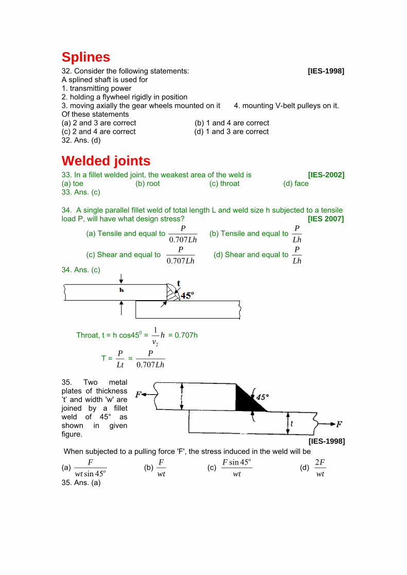
Welded joints 33. In a fillet welded joint, the weakest area of the weld is [IES-2002] (a) toe (b) root (c) throat (d) face 33. Ans. (c) 34. A single parallel fillet weld of total length L and weld size h subjected to a tensile load P, will have what design stress? [IES 2007]
(a) Tensile and equal to Lh
P707.0
(b) Tensile and equal to LhP
(c) Shear and equal to Lh
P707.0
(d) Shear and equal to LhP
34. Ans. (c)
Throat, t = h cos450 = hv2
1 = 0.707h
T = LtP
= Lh
P707.0
35. Two metal plates of thickness ’t’ and width 'w' are joined by a fillet weld of 45° as shown in given figure. [IES-1998] When subjected to a pulling force 'F', the stress induced in the weld will be
(a) sin 45o
Fwt
(b) Fwt
(c) sin 45oFwt
(d) 2Fwt
35. Ans. (a)
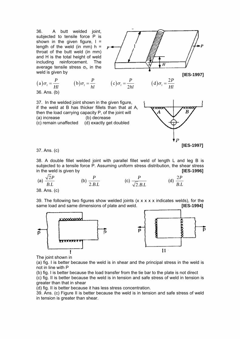
36. A butt welded joint, subjected to tensile force P is shown in the given figure, l = length of the weld (in mm) h = throat of the butt weld (in mm) and H is the total height of weld including reinforcement. The average tensile stress σt, in the weld is given by [IES-1997]
( ) ( ) ( ) ( ) 2a b c d 2t t t t
P P P PHl hl hl Hl
σ σ σ σ= = = =
36. Ans. (b) 37. In the welded joint shown in the given figure, if the weld at B has thicker fillets than that at A, then the load carrying capacity P, of the joint will (a) increase (b) decrease (c) remain unaffected (d) exactly get doubled
[IES-1997] 37. Ans. (c) 38. A double fillet welded joint with parallel fillet weld of length L and leg B is subjected to a tensile force P. Assuming uniform stress distribution, the shear stress in the weld is given by [IES-1996]
(a) 2.P
B L (b)
2. .PB L
(c) 2. .PB L
(d) 2.P
B L
38. Ans. (c) 39. The following two figures show welded joints (x x x x x indicates welds), for the same load and same dimensions of plate and weld. [IES-1994]
The joint shown in (a) fig. I is better because the weld is in shear and the principal stress in the weld is not in line with P (b) fig. I is better because the load transfer from the tie bar to the plate is not direct (c) fig. II is better because the weld is in tension and safe stress of weld in tension is greater than that in shear (d) fig. II is better because it has less stress concentration. 39. Ans. (c) Figure II is better because the weld is in tension and safe stress of weld in tension is greater than shear.
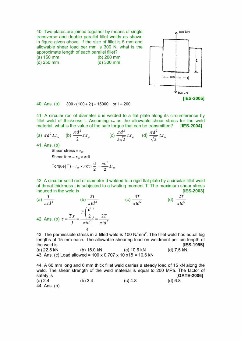
40. Two plates are joined together by means of single transverse and double parallel fillet welds as shown in figure given above. If the size of fillet is 5 mm and allowable shear load per mm is 300 N, what is the approximate length of each parallel fillet? (a) 150 mm (b) 200 mm (c) 250 mm (d) 300 mm
[IES-2005] 40. Ans. (b) ( )300 100 2l 15000 or l 200× + = = 41. A circular rod of diameter d is welded to a flat plate along its circumference by fillet weld of thickness t. Assuming τw as the allowable shear stress for the weld material, what is the value of the safe torque that can be transmitted? [IES-2004]
(a) 2. . wd tπ τ (b) 2
. .2 wd tπ τ (c)
2
. .2 2 w
d tπ τ (d) 2
. .2 w
d tπ τ
41. Ans. (b)
( )
W
W2
W W
Shear stressShear fore dt
d dTorque T dt .t2 2
ττ π
πτ π τ
=
= ×
= × × =
42. A circular solid rod of diameter d welded to a rigid flat plate by a circular fillet weld of throat thickness t is subjected to a twisting moment T. The maximum shear stress induced in the weld is [IES-2003]
(a) 2
Ttdπ
(b) 2
2Ttdπ
(c) 2
4Ttdπ
(d) 3
2Ttdπ
42. Ans. (b) 3 2
.. 22
4
dTT r T
tdJ tdτ
π π
⎛ ⎞⎜ ⎟⎝ ⎠= = =
43. The permissible stress in a filled weld is 100 N/mm2. The fillet weld has equal leg lengths of 15 mm each. The allowable shearing load on weldment per cm length of the weld is [IES-1995] (a) 22.5 kN (b) 15.0 kN (c) 10.6 kN (d) 7.5 kN. 43. Ans. (c) Load allowed = 100 x 0.707 x 10 x15 = 10.6 kN 44. A 60 mm long and 6 mm thick fillet weld carries a steady load of 15 kN along the weld. The shear strength of the weld material is equal to 200 MPa. The factor of safety is [GATE-2006] (a) 2.4 (b) 3.4 (c) 4.8 (d) 6.8 44. Ans. (b)
Threaded fasteners 45. A force ‘F’ is to be transmitted through a square-threaded power screw into a nut. If ‘t’ is the height of the nut and‘d’ is the minor diameter, then which one of the following is the average shear stress over the screw thread? [IES 2007]
(a) dtf
π2
(b)dtFπ
(c) dt
Fπ2
(d) dtF
π4
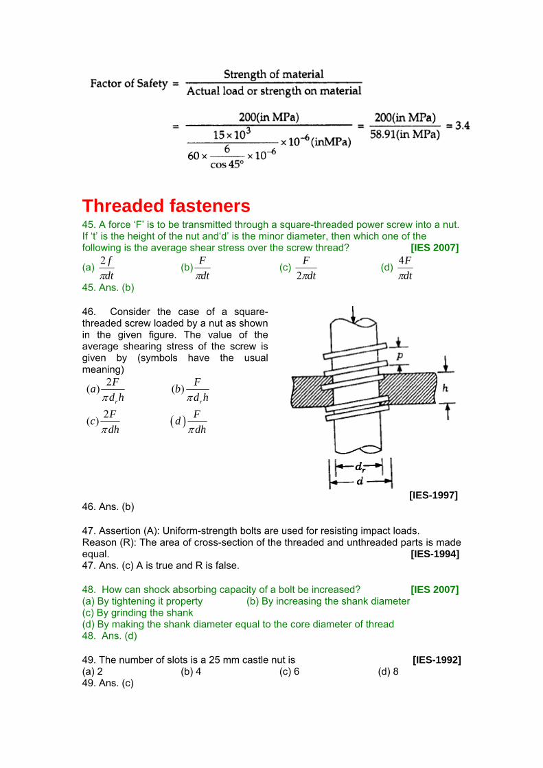
45. Ans. (b) 46. Consider the case of a square-threaded screw loaded by a nut as shown in the given figure. The value of the average shearing stress of the screw is given by (symbols have the usual meaning)
( )
2( ) ( )
2( )
r r
F Fa bd h d hF Fc ddh dh
π π
π π
[IES-1997]
46. Ans. (b) 47. Assertion (A): Uniform-strength bolts are used for resisting impact loads. Reason (R): The area of cross-section of the threaded and unthreaded parts is made equal. [IES-1994] 47. Ans. (c) A is true and R is false. 48. How can shock absorbing capacity of a bolt be increased? [IES 2007] (a) By tightening it property (b) By increasing the shank diameter (c) By grinding the shank (d) By making the shank diameter equal to the core diameter of thread 48. Ans. (d) 49. The number of slots is a 25 mm castle nut is [IES-1992] (a) 2 (b) 4 (c) 6 (d) 8 49. Ans. (c)
50. A threaded nut of M16, ISO metric type, having 2 mm pitch with a pitch diameter of 14.701 mm is to be checked for its pitch diameter using two or three numbers of balls or rollers of the following sizes [GATE-2003] (a) Rollers of 2 mm ϕ (b) Rollers of 1.155 mm ϕ (c) Balls of 2 mm ϕ (d) Balls of 1.155 mm ϕ 50. Ans. (b)
Joints formed by interference fits Answers with Explanation (Objective)
2. Design of friction drives Objective Questions (IES, IAS, GATE)
Couplings 1. Consider the following statements in respect of flexible couplings: [IES-2006] 1. The flanges of flexible coupling are usually made of grey cast iron FG200. 2. In the analysis of flexible coupling, it is assumed that the power is transmitted by the shear resistance of the pins. 3. Rubber bushes with brass lining are provided to absorb misalignment between the two shafts. Which of the statements given above are correct? (a) 1, 2 and 3 (b) Only 1 and 2 (c) Only 2 and 3 (d) Only 1 and 3 1. Ans. (a) Note: It is flexible coupling not fluid coupling. 2. Which of the following stresses are associated with the design of pins in bushed pin-type flexible coupling? [IES-1998] 1. Bearing stress 2. Bending stress 3. Axial tensile stress 4. Transverse shear stress Select the correct answer using the codes given below Codes: (a) 1, 3 and 4 (b) 2, 3 and 4 (c) 1, 2 and 3 (d) 1, 2 and 4 2. Ans. (d) 3. Match List I with List II and select the correct answer using the codes given below the lists:
List I List II [IES-1995] A. Crank shaft 1. Supports the revolving parts and transmits torque. B. Wire shaft 2. Transmits motion between shafts where it is not possible to
effect a rigid coupling between them C. Axle 3. Converts linear motion into rotary motion D. Plain shaft 4. Supports only the revolving parts. Codes: A B C D A B C D (a) 3 2 1 4 (b) 4 2 3 1 (c) 3 2 4 1 (d) 1 4 2 3 3. Ans. (a) 4 The bolts in a rigid flanged coupling connecting two shafts transmitting power are subjected to (a) shear force and bending moment (b) axial force [GATE-1996] (c) torsion (d) torsion and bending moment. 4. Ans. (a)
Clutches
Introduction Friction clutches 5. Which one of the following is not a friction clutch? [IES-2003] (a) Disc or plate clutch (b) Cone clutch (c) Centrifugal clutch (d) Jaw clutch 5. Ans. (d)
GATE Study Material Machine Design(Mechanical Engineering)
Publisher : Faculty Notes Author : Panel Of Experts
Type the URL : http://www.kopykitab.com/product/9850
Get this eBook
50%OFF