Embed Size (px)
Citation preview
MACH3 TURN – ARC MOTION 6/27/2009 REV:0
MACH3 TURN - ARC MOTION PREFACE This is a tutorial about using the G2 and G3 g-codes relative to Mach3 Turn. There is no simple answer to a lot of the arc questions posted on the site relative to the lathe. Yes, a reply is made and it solves a particular problem, but very seldom, will you get the understanding on why that answer worked. Even if you got the direct answer you may not really understand the reply. Most users will only see the arc and don’t understand what influences the way it is interpreted by the controlling program. It’s easy to become confused “real quick”. This tutorial should take away some of that confusion and insight into arc motion. This writing only addresses using G2 and G3 relative to MACH3 in context of Mach3 Turn configuration, LazyCam Turn, LazyTurn, and the arc motion. It does not address offsets, use of other g-codes and is only for the lathe. It is by no means a complete tutorial on how to write g-code. I have deliberately added additional coding not normally required just for illustration reasons. Also some of the code you will see is not “practical” for machining a real part. I took liberty in the verbiage for ease of reading, take no credit for “all” the verbiage, and plagiarize with pride! OVERVIEW Some background info is presented and then the arc formats are defined. The influence of lathe configuration as it relates to arcs is presented and then arc motion is explained. Reversed arcs, crop circles are discussed and finally fun g-code programs are presented. The g-code will be posted along with this writing if you want to run it. BACKGROUND The NIST RS274/NGC LANGUAGE came out as a standard many years ago (1960’s ) and defined code for arc programming. In the early days of Numerical Control “NC” many controllers were only capable of arcs of less than ninety degrees, and they could not cross the quadrant boundaries at 3, 6, 9, and 12 o'clock. Vendors had, and will continue to have, “dialects” of the code which can be interpreted by their controller program. Different programs generate g-code via a post processor that could be specific for a controller program so a specific lathe / machining center could be operated. The controller program may provide options for a flexible configuration. All of the above could have an influence on how the generated G-code for arc’s are interpreted and eventually shown in Mach’s toolpath display. Imagine a turn profile with arcs drawn in diameter units, imported into a CAM program set up for radius which also tweaks point coordinates, posts the code in radius and incremental, and then the file is opened in Mach and your Mach configuration is for incremental movements, absolute arc’s, radius mode and you have reversed arc’s checked. Confused? Lets get unconfused by asking a simple question and then evaluate the answer in depth. What is the specific format required by Mach3 controller as it relates to Mach3Turn? If the requirements are known then arcs may not be that complicated. Ha! Ha! The Using Mach3Turn Manual provides information to answer the above question. Here is what the manual says: The center point of an arc will be interpreted by Mach3 as follows which is compatible with NIST EMC. - In incremental IJ mode I and J ( which represent the center point ) are interpreted as relative to the starting point of a center format arc. NOTE: The K – word is used to locate the arc center in the ZX plane as measured along the Z axis. Therefore I and K are used in the ZX plane and not “J”. This is specifically shown in FIGURE 1.
Page 1 of 19
MACH3 TURN – ARC MOTION 6/27/2009 REV:0
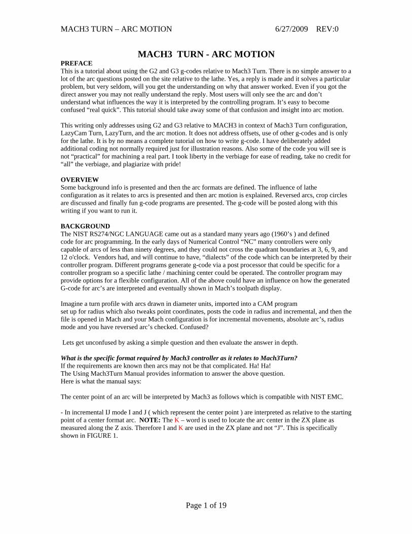
FIGURE 1 - In absolute IJ mode I and J ( which represent the center point ) are the coordinates of the center in the current coordinate system ( after application of the work, tool, and G52/G92 offsets ) as shown in FIGURE 2. Note the use of K and not “J”.
FIGURE 2 - If circles fail to display or cut properly then IJ mode is not compatible with your part program or the way you programmed the parts. The following additional reference can be found in the manual which relates to the G2 and G3 codes: ARC AT FEED RATE – G02 AND G03 A circular arc is specified using either G02 ( clockwise arc ) or G03 ( CCW arc ). The axis of the circle must be parallel to the Y-axis of the machine system. The axis ( or, equivalently, the plane perpendicular to the axis) is selected with G18 ( Y-axis,XZ –plane). ( see ZX PLANE – ARC MOTION ) If cutter radius compensation is active, the motion will differ from the above ( Cutter Compensation is not covered in this writing since it’s a topic by itself and is cancelled in the Initialization String by using a G40 see MACH CONFIGURATION). Two formats are allowed for specifying an arc. We will call these the center format and the radius format. Center Format Arc In the center format, the coordinates of the end point of the arc in the selected plane are specified along with the offsets of the center of the arc.
Page 2 of 19
MACH3 TURN – ARC MOTION 6/27/2009 REV:0
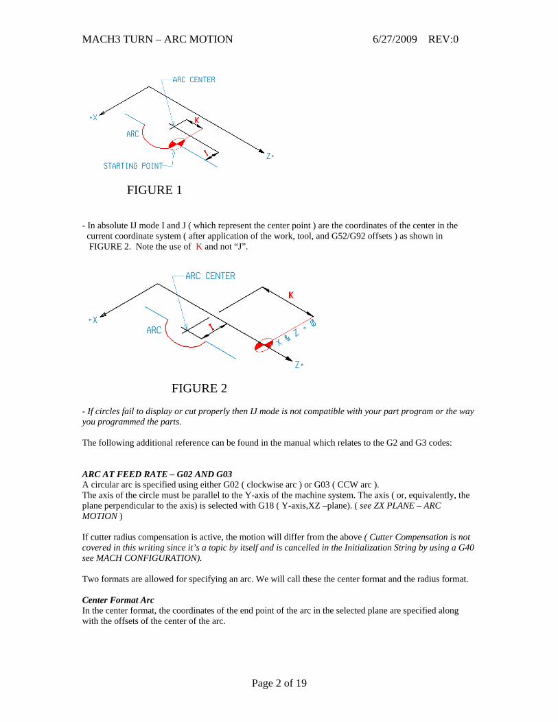
It is an error if: · when the arc is projected on the selected plane, the distance from the current point to the center differs from the distance from the end point to the center by more than 0.0002 inch (if inches are being used) or 0.002 millimeter (if millimeters are being used). The center is specified using the I and K words. There are two ways of interpreting them. - The usual way is that I and K are the center relative to the current point at the start of the arc. This is sometimes called Incremental IJ mode. ( see FIGURE 1 ) - The second way is that I and K specify the center as actual coordinates in the current system. This is rather misleadingly called Absolute IJ mode. ( see FIGURE 2 ) The IJ mode is set using the Configure>State ……menu when Mach3 is setup. ( see MACH CONFIGURATION ) The choice of modes are to provide compatibility with commercial controllers. You will probably find incremental to be best. In Absolute it will, of course usually be necessary to use both I and K words unless by chance the arc’s center is at the origin. NOTE: If arcs come out at silly sizes on the toolpath display then your part program is probably not compatible the IJ mode setting in Mach3. When the XZ-plane is selected, program G02 X Z and I K (or use G03 instead of G02). The axis words are all optional except that at least one of X and Z must be used. I and K are the offsets from the current location or coordinates – depending on IJ mode (the X and Z directions, respectively) of the center of the circle. I and K are optional except that at least one of the two must be used. It is an error if: - X and Z are both omitted - I and K are both omitted In the center format, the radius of the arc is not specified, but it may be found easily as the distance from the center of the circle to either the current point or the end point. Radius Format Arc In the radius format, the coordinates of the end point of the arc in the selected plane are specified along with the radius of the arc.
FIGURE 3 Program G2 X Z R + or - value (or use G3 instead of G2). Note that the X & Z values for the end of the arc are based on incremental or absolute as previously shown in FIGURES 1 & 2 and the R value can be a positive or negative number.
The axis words are all optional except that at least one of the two words for the axes in the selected plane must be used.
Page 3 of 19
MACH3 TURN – ARC MOTION 6/27/2009 REV:0
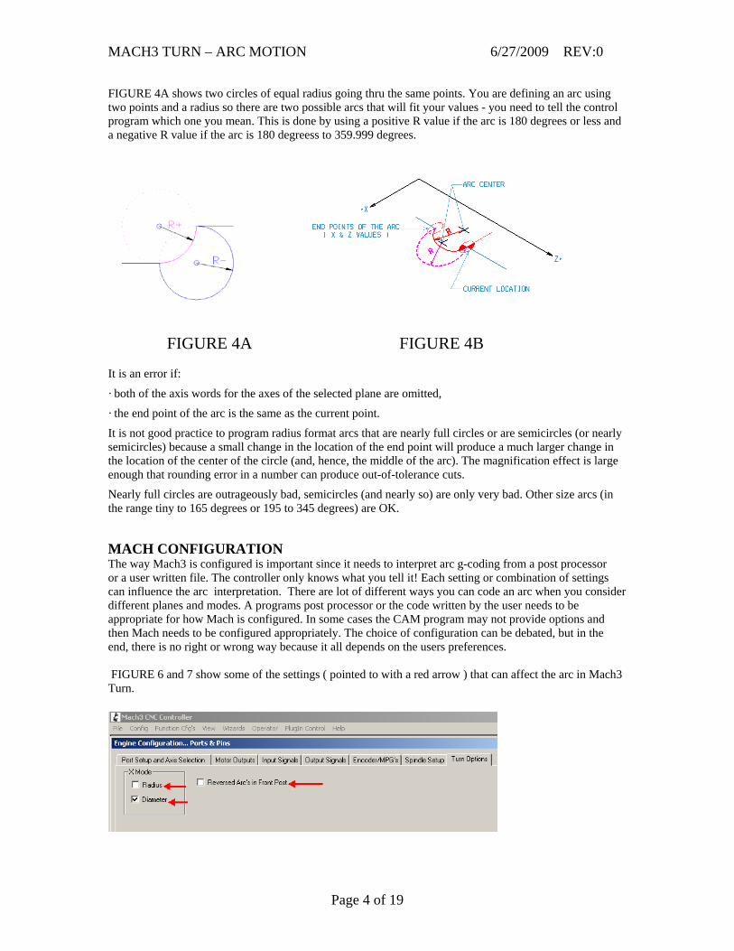
FIGURE 4A shows two circles of equal radius going thru the same points. You are defining an arc using two points and a radius so there are two possible arcs that will fit your values - you need to tell the control program which one you mean. This is done by using a positive R value if the arc is 180 degrees or less and a negative R value if the arc is 180 degreess to 359.999 degrees.
FIGURE 4A FIGURE 4B It is an error if: · both of the axis words for the axes of the selected plane are omitted,
· the end point of the arc is the same as the current point.
It is not good practice to program radius format arcs that are nearly full circles or are semicircles (or nearly semicircles) because a small change in the location of the end point will produce a much larger change in the location of the center of the circle (and, hence, the middle of the arc). The magnification effect is large enough that rounding error in a number can produce out-of-tolerance cuts.
Nearly full circles are outrageously bad, semicircles (and nearly so) are only very bad. Other size arcs (in the range tiny to 165 degrees or 195 to 345 degrees) are OK.
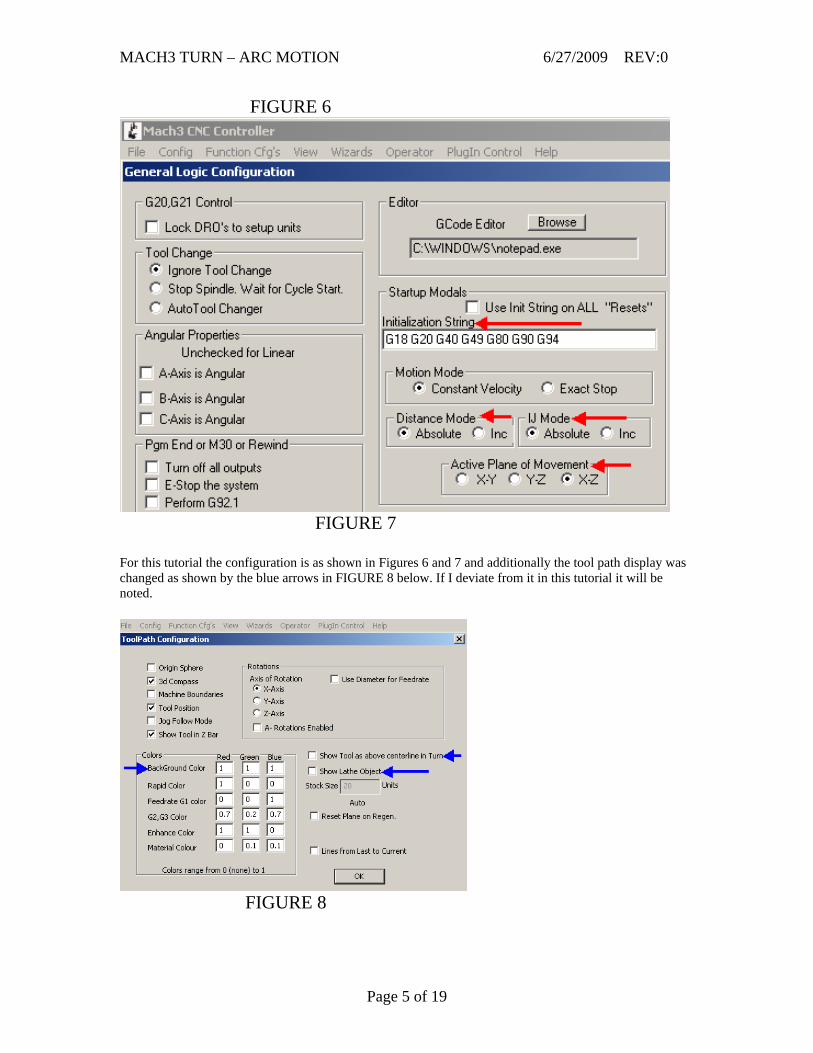
MACH CONFIGURATION The way Mach3 is configured is important since it needs to interpret arc g-coding from a post processor or a user written file. The controller only knows what you tell it! Each setting or combination of settings can influence the arc interpretation. There are lot of different ways you can code an arc when you consider different planes and modes. A programs post processor or the code written by the user needs to be appropriate for how Mach is configured. In some cases the CAM program may not provide options and then Mach needs to be configured appropriately. The choice of configuration can be debated, but in the end, there is no right or wrong way because it all depends on the users preferences. FIGURE 6 and 7 show some of the settings ( pointed to with a red arrow ) that can affect the arc in Mach3 Turn.
Page 4 of 19
MACH3 TURN – ARC MOTION 6/27/2009 REV:0
FIGURE 6
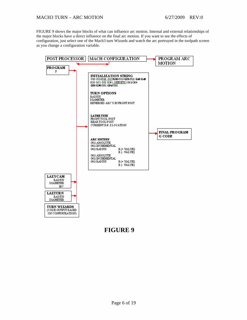
FIGURE 7 For this tutorial the configuration is as shown in Figures 6 and 7 and additionally the tool path display was changed as shown by the blue arrows in FIGURE 8 below. If I deviate from it in this tutorial it will be noted.
FIGURE 8
Page 5 of 19
MACH3 TURN – ARC MOTION 6/27/2009 REV:0
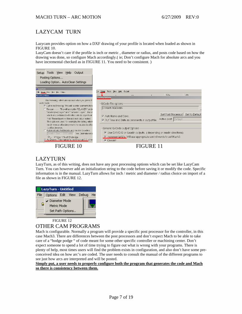
FIGURE 9 shows the major blocks of what can influence arc motion. Internal and external relationships of the major blocks have a direct influence on the final arc motion. If you want to see the effects of configuration, just select one of the Mach3 turn Wizards and watch the arc portrayed in the toolpath screen as you change a configuration variable.
FIGURE 9
Page 6 of 19
MACH3 TURN – ARC MOTION 6/27/2009 REV:0
LAZYCAM TURN Lazycam provides option on how a DXF drawing of your profile is located when loaded as shown in FIGURE 10. LasyCam doesn’t care if the profile is inch or metric , diameter or radius, and posts code based on how the drawing was done, so configure Mach accordingly.( ie; Don’t configure Mach for absolute arcs and you have incremental checked as in FIGURE 11. You need to be consistent. )
FIGURE 10 FIGURE 11 LAZYTURN LazyTurn, as of this writing, does not have any post processing options which can be set like LazyCam Turn. You can however add an initialization string to the code before saving it or modify the code. Specific information is in the manual. LazyTurn allows for inch / metric and diameter / radius choice on import of a file as shown in FIGURE 12.
FIGURE 12 OTHER CAM PROGRAMS Mach is configurable. Normally a program will provide a specific post processor for the controller, in this case Mach3. There are differences between the post processors and don’t expect Mach to be able to take care of a “hodge podge “ of code meant for some other specific controller or machining center. Don’t expect someone to spend a lot of time trying to figure out what is wrong with your programs. There is plenty of help, most times users will find the problem exists in configuration, and also don’t have some pre-conceived idea on how arc’s are coded. The user needs to consult the manual of the different programs to see just how arcs are interpreted and will be posted. Simply put, a user needs to properly configure both the program that generates the code and Mach so there is consistency between them.
Page 7 of 19
MACH3 TURN – ARC MOTION 6/27/2009 REV:0
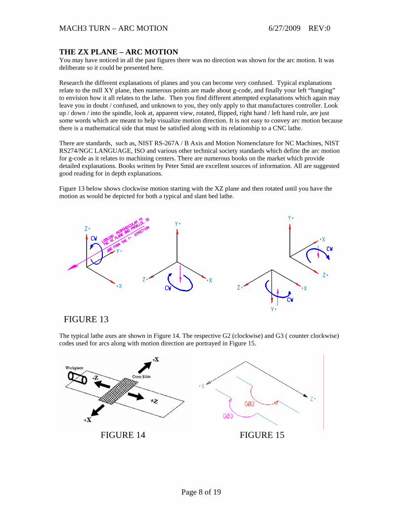
THE ZX PLANE – ARC MOTION You may have noticed in all the past figures there was no direction was shown for the arc motion. It was deliberate so it could be presented here. Research the different explanations of planes and you can become very confused. Typical explanations relate to the mill XY plane, then numerous points are made about g-code, and finally your left “hanging” to envision how it all relates to the lathe. Then you find different attempted explanations which again may leave you in doubt / confused, and unknown to you, they only apply to that manufactures controller. Look up / down / into the spindle, look at, apparent view, rotated, flipped, right hand / left hand rule, are just some words which are meant to help visualize motion direction. It is not easy to convey arc motion because there is a mathematical side that must be satisfied along with its relationship to a CNC lathe. There are standards, such as, NIST RS-267A / B Axis and Motion Nomenclature for NC Machines, NIST RS274/NGC LANGUAGE, ISO and various other technical society standards which define the arc motion for g-code as it relates to machining centers. There are numerous books on the market which provide detailed explanations. Books written by Peter Smid are excellent sources of information. All are suggested good reading for in depth explanations. Figure 13 below shows clockwise motion starting with the XZ plane and then rotated until you have the motion as would be depicted for both a typical and slant bed lathe.
FIGURE 13 The typical lathe axes are shown in Figure 14. The respective G2 (clockwise) and G3 ( counter clockwise) codes used for arcs along with motion direction are portrayed in Figure 15.
FIGURE 14 FIGURE 15
Page 8 of 19
MACH3 TURN – ARC MOTION 6/27/2009 REV:0
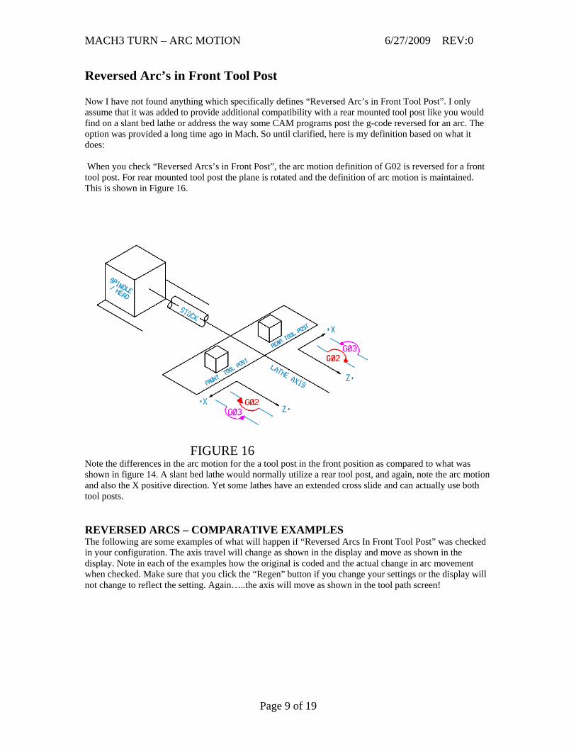
Reversed Arc’s in Front Tool Post Now I have not found anything which specifically defines “Reversed Arc’s in Front Tool Post”. I only assume that it was added to provide additional compatibility with a rear mounted tool post like you would find on a slant bed lathe or address the way some CAM programs post the g-code reversed for an arc. The option was provided a long time ago in Mach. So until clarified, here is my definition based on what it does: When you check “Reversed Arcs’s in Front Post”, the arc motion definition of G02 is reversed for a front tool post. For rear mounted tool post the plane is rotated and the definition of arc motion is maintained. This is shown in Figure 16.
FIGURE 16 Note the differences in the arc motion for the a tool post in the front position as compared to what was shown in figure 14. A slant bed lathe would normally utilize a rear tool post, and again, note the arc motion and also the X positive direction. Yet some lathes have an extended cross slide and can actually use both tool posts. REVERSED ARCS – COMPARATIVE EXAMPLES The following are some examples of what will happen if “Reversed Arcs In Front Tool Post” was checked in your configuration. The axis travel will change as shown in the display and move as shown in the display. Note in each of the examples how the original is coded and the actual change in arc movement when checked. Make sure that you click the “Regen” button if you change your settings or the display will not change to reflect the setting. Again…..the axis will move as shown in the tool path screen!
Page 9 of 19
MACH3 TURN – ARC MOTION 6/27/2009 REV:0
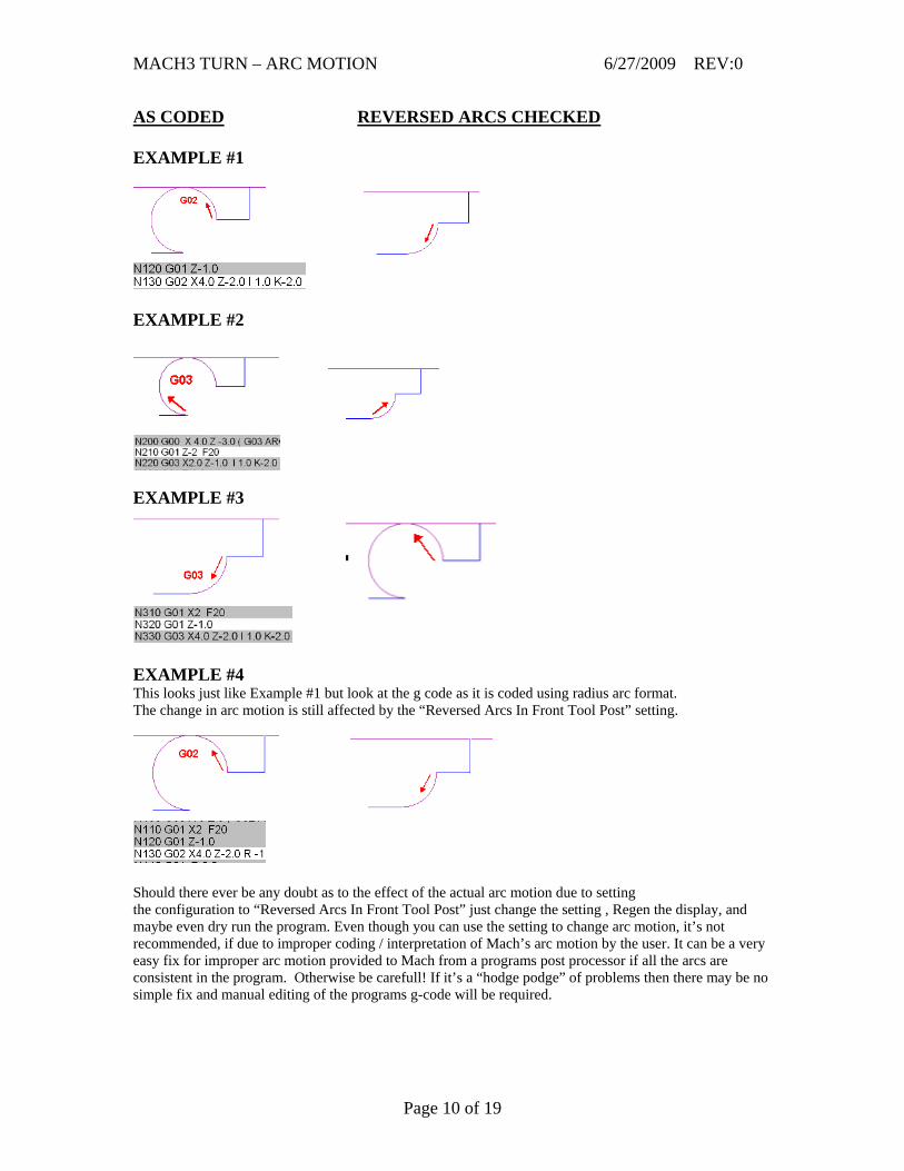
AS CODED REVERSED ARCS CHECKED EXAMPLE #1
EXAMPLE #2
EXAMPLE #3
EXAMPLE #4 This looks just like Example #1 but look at the g code as it is coded using radius arc format. The change in arc motion is still affected by the “Reversed Arcs In Front Tool Post” setting.
Should there ever be any doubt as to the effect of the actual arc motion due to setting the configuration to “Reversed Arcs In Front Tool Post” just change the setting , Regen the display, and maybe even dry run the program. Even though you can use the setting to change arc motion, it’s not recommended, if due to improper coding / interpretation of Mach’s arc motion by the user. It can be a very easy fix for improper arc motion provided to Mach from a programs post processor if all the arcs are consistent in the program. Otherwise be carefull! If it’s a “hodge podge” of problems then there may be no simple fix and manual editing of the programs g-code will be required.
Page 10 of 19
MACH3 TURN – ARC MOTION 6/27/2009 REV:0
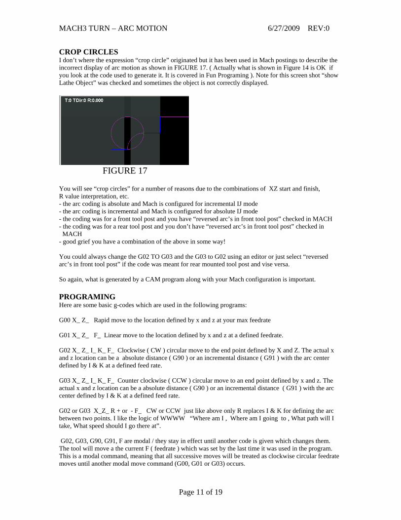
CROP CIRCLES I don’t where the expression “crop circle” originated but it has been used in Mach postings to describe the incorrect display of arc motion as shown in FIGURE 17. ( Actually what is shown in Figure 14 is OK if you look at the code used to generate it. It is covered in Fun Programing ). Note for this screen shot “show Lathe Object” was checked and sometimes the object is not correctly displayed.
FIGURE 17 You will see “crop circles” for a number of reasons due to the combinations of XZ start and finish, R value interpretation, etc. - the arc coding is absolute and Mach is configured for incremental IJ mode - the arc coding is incremental and Mach is configured for absolute IJ mode - the coding was for a front tool post and you have “reversed arc’s in front tool post” checked in MACH - the coding was for a rear tool post and you don’t have “reversed arc’s in front tool post” checked in MACH - good grief you have a combination of the above in some way! You could always change the G02 TO G03 and the G03 to G02 using an editor or just select “reversed arc’s in front tool post” if the code was meant for rear mounted tool post and vise versa. So again, what is generated by a CAM program along with your Mach configuration is important. PROGRAMING Here are some basic g-codes which are used in the following programs: G00 X_ Z_ Rapid move to the location defined by x and z at your max feedrate G01 X_ Z_ F_ Linear move to the location defined by x and z at a defined feedrate. G02 X_ Z_ I_ K_ F_ Clockwise ( CW ) circular move to the end point defined by X and Z. The actual x and z location can be a absolute distance ( G90 ) or an incremental distance ( G91 ) with the arc center defined by I & K at a defined feed rate. G03 X_ Z_ I_ K_ F_ Counter clockwise ( CCW ) circular move to an end point defined by x and z. The actual x and z location can be a absolute distance ( G90 ) or an incremental distance ( G91 ) with the arc center defined by I & K at a defined feed rate. G02 or G03 X_Z_ R + or - F_ CW or CCW just like above only R replaces I & K for defining the arc between two points. I like the logic of WWWW “Where am I , Where am I going to , What path will I take, What speed should I go there at”. G02, G03, G90, G91, F are modal / they stay in effect until another code is given which changes them. The tool will move a the current F ( feedrate ) which was set by the last time it was used in the program. This is a modal command, meaning that all successive moves will be treated as clockwise circular feedrate moves until another modal move command (G00, G01 or G03) occurs.
Page 11 of 19
MACH3 TURN – ARC MOTION 6/27/2009 REV:0
G04 P_ Dwell is a pause in seconds. ( This was added to the program code so the movement would pause before continuing on for each of the arc move examples.) NOTE THE FOLLOWING COMMENTS: GENERAL 1. Mach designates the XZ plane as G18 2. F is modal and if not in the block Mach will use the last F used in the program. Sometimes a slower F for for arcs when using CV are required depending on your motor tuning. 3. I & K are used for XZ axis, I & J will give an error in G18. 4. I & K & R used on the same line will give an error. 5. I & K values will be the same in both incremental and absolute mode if the arc start point happens to be program zero and no error will be reported. Note that because of the X & Z value, you may not get the arc motion you desired. X & Z is defined by G90 or G91 mode. 6. A specific feed rate should be specified for G01, G02, G03 otherwise the programs default feed rates are used. 7. In both formats the G02 or G03 is optional in the line if it is the current motion mode. G02 & G03 are MODAL: once commanded, it remains effective until a G00, G01, or G02 is commanded. 8. Arc motion will be as programmed and takes precedence over the default plane when the arc programming block is complete. 9. I & K should not be replaced with an R value since I & K is unique and R is ambiguous. But there are cases where R just happens to be the same as the I & K, and in that case you can replace them with R but an additional clarifier + or - may be required. 10. Mach has an ERROR TOLERANCE. It is an error when the arc is projected on the selected plane, the distance from the current point to the center differs from the distance from the end point to the center by more than 0.0002 inch (if inches are being used) or 0.002 millimeter (if millimeters are being used). Take care when doing hand calculations and also using code generated by different programs. ABSOLUTE 1. The absolute values of I K are the distances from the program zero, not home zero even though program, home, and machine coordinates can all be at the same zero. 2. The end point of the arc can be the same as the current point / arc starting point in the program, but, you would be cutting a 360 degree arc which is not very practical when machining on the lathe. Mach provides for full circular arc motion. INCREMENTAL 24. With incremental positioning, all positions are based on the previous position, so X and Z defines the arc end point based on the previous X, Z end point (arc start). This is different than programming using absolute positioning where X and Z define the arc end point based on the program origin. RADIUS 1. Two mathematical possibilities exist for R and you need to define which one you want to the controller and this is accomplished by using the R + or – value. 2. Mach accepts direct R radius mode ( arc’s need not be broken into quadrants ). Older controls may not provide for arc’s greater than 90 degrees so you may need to spit arcs up if using the code with some other controller. 3. The start point for R ( radius mode ) is defined by where the circular interpretation begins and is relative to the cutting motion. The R radius is unique. 4. The radius R must be non-zero. 5. I & K should be used for a full circle rather than R ( which is not practical machining on the lathe ). 6. If the arc sweeps a 180 degree angle, it doesn’t matter whether R is negative or positive. Of course you have the choice of breaking the arc into two segments / two program moves.
Page 12 of 19
MACH3 TURN – ARC MOTION 6/27/2009 REV:0
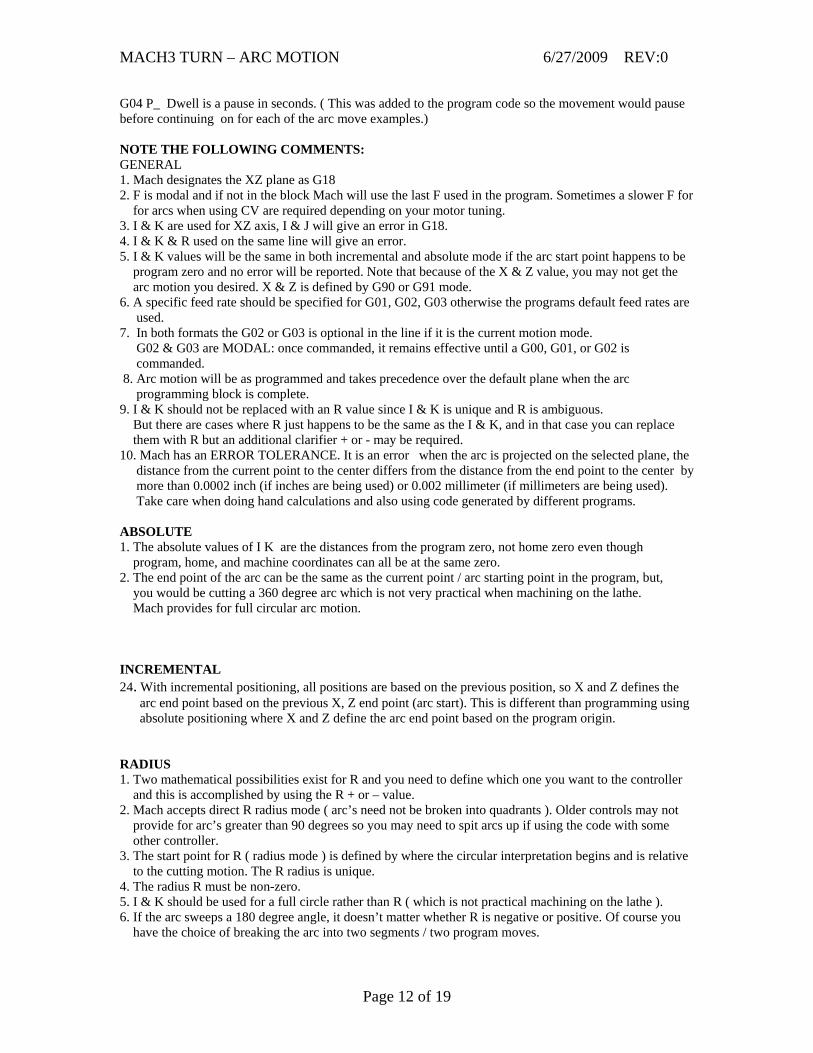
FUN PROGRAMS FOR ARC MOTION You should only add code which requires changes and nothing more, so excuse my poor style. It was done for a reason, namely, so you could break the program up and run each part of the arc programs individually. G02 G03 ABSOLUTE CENTER ARC MOTION This program starts at Z= 0, X=0, goes back and forth along the Z axis three times doing six different arc motions. The axis movement is towards the spindle doing a G02 then returning along the same path but doing a G03. It will pause for 2 seconds before reversing direction / going back to program zero and pause again before starting the second set of arc motions ……then the third set of arc motions. Below is a screen display of the program.
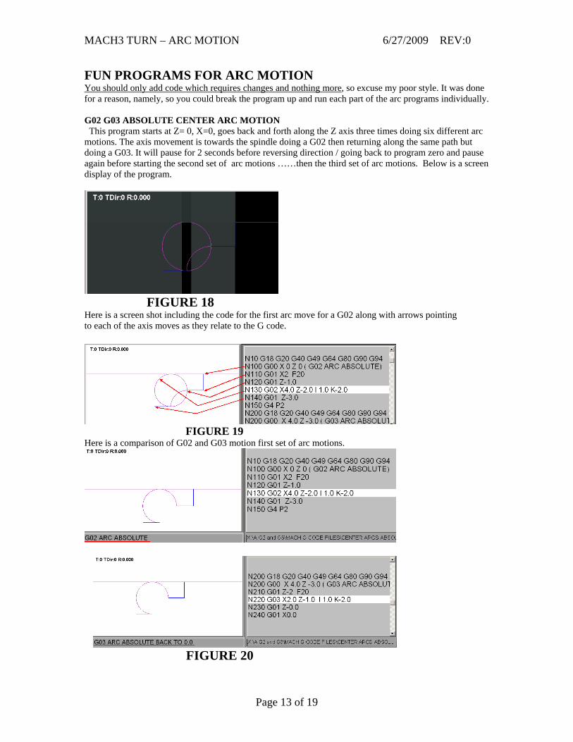
FIGURE 18 Here is a screen shot including the code for the first arc move for a G02 along with arrows pointing to each of the axis moves as they relate to the G code.
FIGURE 19 Here is a comparison of G02 and G03 motion first set of arc motions.
FIGURE 20
Page 13 of 19
MACH3 TURN – ARC MOTION 6/27/2009 REV:0
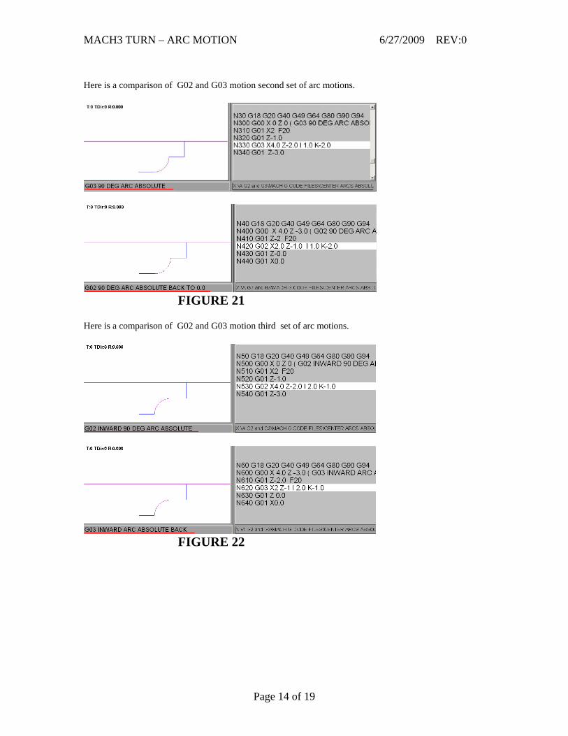
Here is a comparison of G02 and G03 motion second set of arc motions.
FIGURE 21 Here is a comparison of G02 and G03 motion third set of arc motions.
FIGURE 22
Page 14 of 19
MACH3 TURN – ARC MOTION 6/27/2009 REV:0
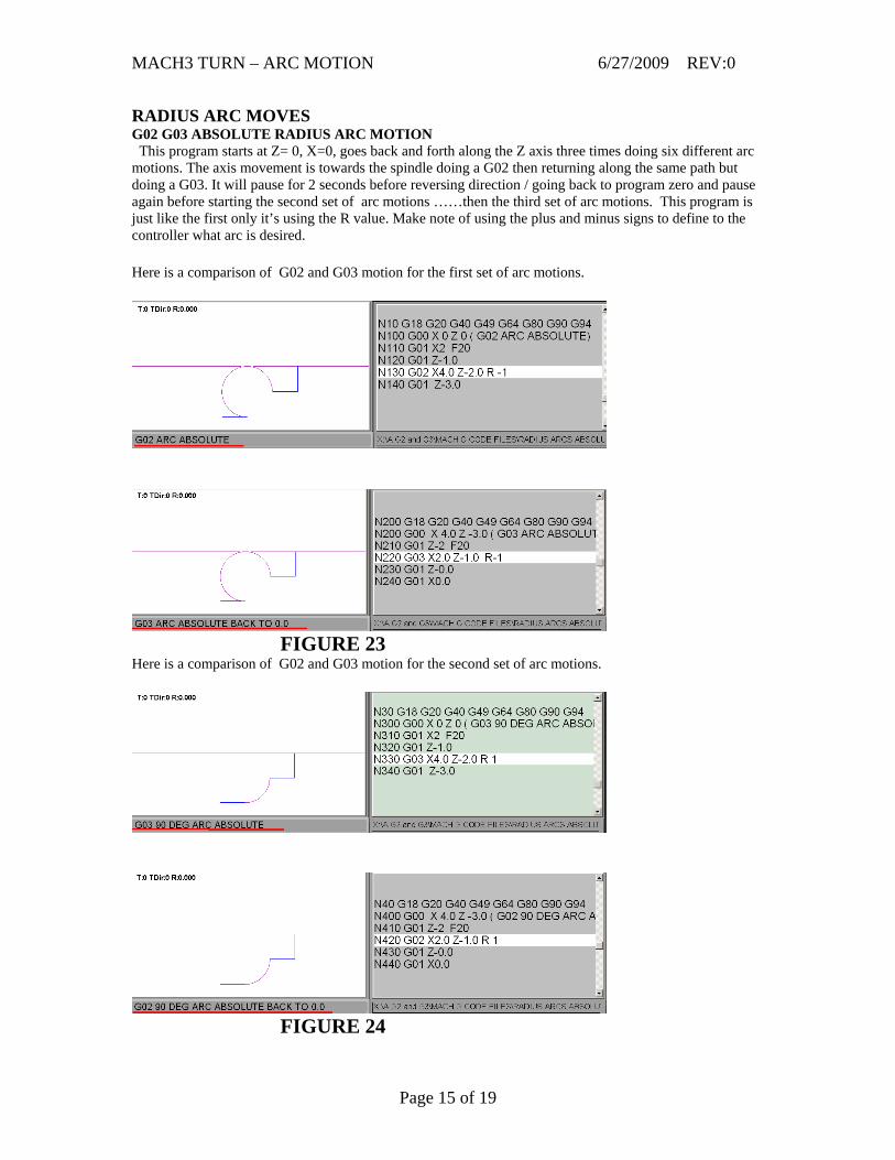
RADIUS ARC MOVES G02 G03 ABSOLUTE RADIUS ARC MOTION This program starts at Z= 0, X=0, goes back and forth along the Z axis three times doing six different arc motions. The axis movement is towards the spindle doing a G02 then returning along the same path but doing a G03. It will pause for 2 seconds before reversing direction / going back to program zero and pause again before starting the second set of arc motions ……then the third set of arc motions. This program is just like the first only it’s using the R value. Make note of using the plus and minus signs to define to the controller what arc is desired. Here is a comparison of G02 and G03 motion for the first set of arc motions.
FIGURE 23 Here is a comparison of G02 and G03 motion for the second set of arc motions.
FIGURE 24
Page 15 of 19
MACH3 TURN – ARC MOTION 6/27/2009 REV:0
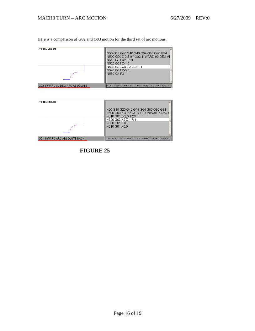
Here is a comparison of G02 and G03 motion for the third set of arc motions.
FIGURE 25
Page 16 of 19
MACH3 TURN – ARC MOTION 6/27/2009 REV:0
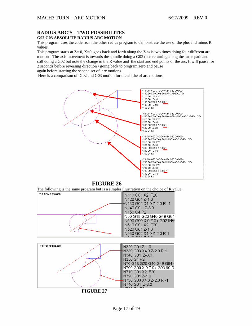
RADIUS ARC’S – TWO POSSIBILITES G02 G03 ABSOLUTE RADIUS ARC MOTION This program uses the code from the other radius program to demonstrate the use of the plus and minus R values. This program starts at Z= 0, X=0, goes back and forth along the Z axis two times doing four different arc motions. The axis movement is towards the spindle doing a G02 then returning along the same path and still doing a G02 but note the change in the R value and the start and end points of the arc. It will pause for 2 seconds before reversing direction / going back to program zero and pause again before starting the second set of arc motions. Here is a comparison of G02 and G03 motion for the all the of arc motions.
FIGURE 26 The following is the same program but is a simpler illustration on the choice of R value.
FIGURE 27
Page 17 of 19
MACH3 TURN – ARC MOTION 6/27/2009 REV:0
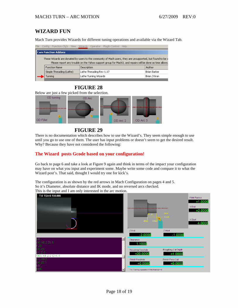
WIZARD FUN Mach Turn provides Wizards for different tuning operations and available via the Wizard Tab.
FIGURE 28 Below are just a few picked from the selection.
FIGURE 29 There is no documentation which describes how to use the Wizard’s. They seem simple enough to use until you go to use one of them. The user has input problems or doesn’t seem to get the desired result. Why? Because they have not considered the following: The Wizard posts Gcode based on your configuration! Go back to page 6 and take a look at Figure 9 again and think in terms of the impact your configuration may have on what you input and experiment some. Maybe write some code and compare it to what the Wizard post’s. That said, thought I would try one for kick’s. The configuration is as shown by the red arrows in Mach Configuration on pages 4 and 5. So it’s Diameter, absolute distance and IK mode, and no reversed arcs checked. This is the input and I am only interested in the arc motion.
Page 18 of 19
MACH3 TURN – ARC MOTION 6/27/2009 REV:0
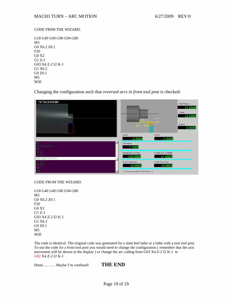
CODE FR0M THE WIZARD: G18 G40 G49 G90 G94 G80 M3 G0 X6.2 Z0.1 F20 G0 X2 G1 Z-1 G03 X4 Z-2 I2 K-1 G1 X6.2 G0 Z0.1 M5 M30 Changing the configuration such that reversed arcs in front tool post is checked:
CODE FROM THE WIZARD: G18 G40 G49 G90 G94 G80 M3 G0 X6.2 Z0.1 F20 G0 X2 G1 Z-1 G03 X4 Z-2 I2 K-1 G1 X6.2 G0 Z0.1 M5 M30 The code is identical. The original code was generated for a slant bed lathe or a lathe with a rear tool post. To use the code for a front tool post you would need to change the configuration ( remember that the axis movement will be shown in the display ) or change the arc coding from G03 X4 Z-2 I2 K-1 to G02 X4 Z-2 I2 K-1
Hmm………. Maybe I’m confused! THE END
Page 19 of 19