Embed Size (px)
Citation preview
Mach 3 G100 Setup Guide 9/19/2007
Chaoticone Page 1 of 32
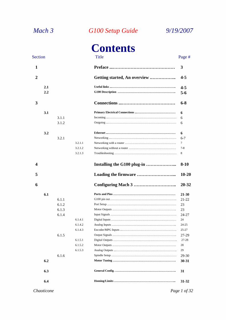
ContentsSection Title Page #
1 Preface ...…………………………………… 3
2 Getting started, An overview .…………….. 4-5
2.1 Useful links ...……………………………………………………….. 4-52.2 G100 Description ………………………………………………….. 5-6
3 Connections ...……………………………… 6-8
3.1 Primary Electrical Connections ...………………………………… 6
3.1.1 Incoming ...…………………………………………………………… 6
3.1.2 Outgoing ...…………………………………………………………… 6
3.2 Ethernet ..…………………………………………………………… 6
3.2.1 Networking ...………………………………………………………… 6-73.2.1.1 Networking with a router ……………………………………………. 7
3.2.1.2 Networking without a router ………………………………………… 7-8
3.2.1.3 Troubleshooting ……………………………………………………… 8
4 Installing the G100 plug-in ………………... 8-10
5 Loading the firmware ……………………... 10-20
6 Configuring Mach 3 ……………………….. 20-32
6.1 Ports and Pins ……………………………………………………… 21-30
6.1.1 G100 pin out………………………………………………………….. 21-22
6.1.2 Port Setup ……………………………………………………………. 23
6.1.3 Motor Outputs ……………………………………………………….. 23
6.1.4 Input Signals …………………………………………………………. 24-276.1.4.1 Digital Inputs ………………………………………………………… 24
6.1.4.2 Analog Inputs ………………………………………………………... 24-25
6.1.4.3 Encoder/MPG Inputs ...………………………………………………. 25-27
6.1.5 Output Signals ……………………………………………………….. 27-296.1.5.1 Digital Outputs ……………………………………………………….. 27-28
6.1.5.2 Motor Outputs .………………………………………………………. 28
6.1.5.3 Analog Outputs ...…………………………………………………….. 29
6.1.6 Spindle Setup ………………………………………………………… 29-30
6.2 Motor Tuning ………………………………………………………. 30-31
6.3 General Config. …………………………………………………….. 31
6.4 Homing/Limits ……………………………………………………... 31-32

Mach 3 G100 Setup Guide 9/19/2007
Page 2 of 32 Chaoticone
7 Known Issues ...…………………………….. 32
8 Revisions List ………………………………. 32
9 Trouble Shooting …………………………... 32

Mach 3 G100 Setup Guide 9/19/2007
Chaoticone Page 3 of 32
1. Preface
Any machine tool is potentially dangerous. Computer controlled machines are potentiallymore dangerous than manual ones because, for example, a computer is quite preparedto rotate an 8" unbalanced cast iron four-jaw chuck at 3000 rpm, to plunge a panel-fieldingrouter cutter deep into a piece of oak or to mill the clamps holding your work to the table!
This manual tries to give you guidance on safety precautions and techniques but because we do notknow the details of your machine or local conditions we can accept no responsibility for theperformance of any machine or any damage or injury caused by its use. It is your responsibility toensure that you understand the implications of what you design and build and to comply with anylegislation and codes of practice applicable to your country or state.
If you are in any doubt you must seek guidance from a professionally qualified expert rather thanrisk injury to yourself or to others.
This document is intended to give details about how to set-up your G100 for the Mach3 system. Itassumes that you are familiar with the contents of Using Mach2Mill or Using Mach2Turn (still inpreparation) as appropriate.
You are strongly advised to join the online discussion forum for Mach3. A link to join it is on theCompany page at http://www.artsoftcontrols.com/ You should be aware that, while the forum has manyengineers with a vast range of experience as participants, it does not constitute a substitute for a machinetool manufacturer's support network. If your application requires this level of support then you should buythe system from a local distributor or an OEM with a distributor network. In that way you will get thebenefits of Mach3 with the possibility of on-site support.
Certain portions of text in this manual are printed "greyed out". They generally describe features foundin machine controllers but which are not presently implemented in Mach2. The description of a greyedout feature here is not to be taken as a commitment to implement it at any given time in the future.
Thanks are due to numerous people including the original team who worked at National Institute forStandards and Testing (NIST) on the EMC project and the innumerable users of Mach3 without whoseexperience, materials and constructive comments this manual could not have been written. Particularthanks are due to Olivier Adler and Brian Barker for their contributions to the development anddocumentation of Wizards and to Les Newell for his KeyGrabber (which now grabs a lot more than keystrokes!).
ArtSoft Corporation is dedicated to continual improvement of its products, so suggestions forenhancements, corrections and clarifications will be gratefully received.
Art Fenerty and John Prentice assert their right to be identified as the authors of this work. The right tomake copies of this manual is granted solely for the purpose of evaluating and/or using licensed ordemonstration copies of Mach3. It is not permitted, under this right, for third parties to charge forcopies of this manual.
Every effort has been made to make this manual as complete and as accurate as possible but no warrantyor fitness is implied. The information provided is on an "as is" basis. The authors and publisher shallhave neither liability nor responsibility to any person or entity with respect to any loss or damagesarising from the information contained in this manual, Use of the manual is covered by the licenseconditions to which you must agree when installing Mach3 software. Windows XP and Windows 2000are registered trademarks of Microsoft Corporation. If other trademarks are used in this manual but notacknowledged please notify ArtSoft Corporation so this can be remedied in subsequent editions.
Mach 3 G100 Setup Guide 9/19/2007
Page 4 of 32 Chaoticone
2. Getting Started, an Overview
When working with Mach3's firmware, the G100 communicates through a special binary protocolunlike its geckomotion native firmware. This requires the G100 be flashed with the Mach3 flavour offirmware. All axis can run independently or in coordination with other axis. In this manual we will begoing over the steps taken to get your G100 setup and running under the control of Mach 3. It is myintention to be very clear direct, and take the shortest path to reach the desired goal. There is a wealth ofinformation that has been left out of this G100 Setup Guide on purpose. I recommend you look over themanual in its entirety and get familiar with it before you begin. I would also recommend at this pointyou download and install the latest version of Mach 3. The latest version can be found at.http://www.artsoftcontrols.com/artsoft/downloads/downloads.htm Also, download the G100 plug-inthat can found at. http://www.artsoftcontrols.com/artsoft/plugin.htm The installation of the G100 plug-in is covered later in section 4.
This manual covers the following. Section numbers have been listed to avoid confusion.3. Connections.
This Section will tell you how to get your G100 wired in to the point of being able to power theG100 and communicate thru an Ethernet connection. It does not cover any inputs or outputs
4. Installing the G100 plug-in.This section covers in detail the downloading and installation process for installing the G100plug-in.
5. Loading the firmwareThis section covers in detail the loading of the firmware.
6. Configuring Mach3.
This section covers in detail the settings you will set from within Mach3. You will open yourMach 3 Profile to get to these settings. Located in the upper left hand corner, Config. tab.
7. Known IssuesThis section list known issues.
8. Revisions ListThis section list the revisions made to plug ins, firmware, and this manual by date.
9. Trouble ShootingThis section will suggest possible causes of problems and remedies for each. This section willmost likely be the one that is most often edited as problems produce and remedies are acquired.
2.1 Useful Links.
Below is a list of links that you may find helpful while in the process of getting your G100 Setuphttp://www.artsoftcontrols.com/ Artsoft’s home pagehttp://www.artsoftcontrols.com/artsoft/downloads/downloads.htm Download Mach 3 here.http://www.artsoftcontrols.com/artsoft/plugin.htm Download the G100 plug-in herehttp://www.artsoftcontrols.com/forum/index.php Artsoft’s forum home pagehttp://www.artsoftcontrols.com/forum/index.php?board=13.0 Artsoft forum dedicated boardto the G100 and Mach3http://www.geckodrive.com/index.cfm Gecko drives home page.http://www.geckodrive.com/product.cfm?pid=19 Gecko drives G100 page.http://www.netspec.com/helpdesk/wiredoc.html Network cables link 1.

Mach 3 G100 Setup Guide 9/19/2007
Chaoticone Page 5 of 32
http://www.peakelec.co.uk/content/ethernet.html Network cables link 2
2.2 G100 DESCRIPTION:
The G100 is a 6-axis motion controller. It uses USB or Ethernet communication with a host PC to executemotion control and I/O commands. The axis outputs use a Step/Direction interface to motor drives.Each axis has an associated quadrature encoder input. The G100 also has 22 general purpose inputs, 16general purpose outputs, 4 analog to digital inputs and 4 digital to analog outputs. Each digital input andoutput has an LED indicator. USB is not used with Mach
The G100 uses an FPGA to generate axis step pulse timing and an 8-bit microcomputer to calculatemotion control flow. Communication with the G100 is via text string commands and replies. All axiscan run independently or in coordination with other axis. Coordinated axis motion is vector based. Theassociated axis accelerate, run and decelerate simultaneously while maintaining exact speed ratios.
The G100 uses a unique method of motion control. The FPGA produces step pulse frequencies proportional to16-bit word. This results 32,767 CW and 32,767 CCW evenly spaced step-pulse frequencies per range. Thecommanded frequency can only be changed at fixed rate of 1,024 times per second. The same crystaloscillator time base generates step pulse frequencies and the update rate. The axis position is a runningsum of the issued velocities.
The 1,024 updates per second also apply to all inputs and outputs. Inputs, including analog are sampled atthat rate and all outputs, including analog are updated at that rate.
G100 HARDWARE FEATURES:
1) 8 step-pulse frequency ranges. 65,535 CW and CCW speeds per range. Maximum step-pulsefrequency is 4.194304 MHz. Maximum step-pulse jitter is 125 ns. Step and direction outputsare 5V logic, +/-24 mA current drive per output. Step-pulse indicator LED is activity driven; itis lit when output is pulsing.
2) 6 quadrature encoder inputs including index channel. Maximum encoder count rate is 1 MHz.Encoder inputs are filtered and have indicator LEDs on each input.
3) 16 general-purpose outputs. The outputs are rated at 100mA, 24VDC maximum per output.The outputs are suitable for driving DC relay coils. Each output has an indicator LED which lightswhen an output is “on”.
4) 22 general-purpose inputs. The inputs can be activated by SPST switches to ground, by open-collector sensors or by 5V logic levels. The inputs are filtered and protected to +/- 50VDC. Eachinput has an indicator LED that lights when an input is grounded.
5) 4 Digital to analog outputs. Each output is a 0 to 5V (0 to 10V optional) op-amp output and 8-bit resolution.
6) 4 Analog to digital inputs. Each input takes a 0 to 5V (0 to 10V optional) input voltage range.The resolution is 8-bit and the input impedance is 2.2K.
7) The G100 requires a 12VDC to 24VDC power supply rated at 1.5A. It supplies an internallyregulated 5VDC to the terminal block outputs.
Mach 3 G100 Setup Guide 9/19/2007
Page 6 of 32 Chaoticone
8) The G100 has both a USB and an Ethernet interface. USB is not used with Mach
9) The G100 has a 2.5” by 7.375” mounting area footprint and is 1.5” high ( 63.5mm by 187mm by38mm). The weight is 10 ounces (284 gm). The enclosure is black anodized aluminum. The G100has 96 bare-wire type terminal block locations. The terminal blocks have a 3.5mm pitch.
3. Connections
This Section will tell you how to get your G100 wired in to the point of being able to power theG100 and communicate thru an Ethernet connection. It does not cover any inputs, or outputs. Nor does itcover the USB connection as you should not need it to for use with Mach 3.
3.1 Primary Electrical Connections.With the G100 you will have two types of power, the first is the power supplied to the G100. Thesecond is the power the G100 supplies to other devices such as home, limit, and input switches.
3.1.1 Incoming Power.The G100 requires a 12VDC to 24VDC power supply rated at 1.5A. This can beaccomplished in one of two ways. There is a power jack at one end of the G100 forplugging a wall transformer into. This is a center positive (+) connector. The second way isto supply 12VDC to 24VDC + to the terminal marked +24V and a wire connecting theterminal marked GND to ground. Either way supplies an internally regulated 5VDC to theterminal block outputs. Inputs will be covered later in Section 6.1.4, Inputs Signals.
3.1.2 Outgoing Power.At this point we will only point out the fact that the terminals marked +5V is an outgoingpower source. You do not need to supply 5V+ to any of these as you would with someother breakout boards. Outputs will be covered later in Section 6.1.5, Output Signals
3.2 Ethernet.The G100 uses an Ethernet connection to communicate with Mach 3. It is located in the endopposite of the power connection. As with the incoming power connection, you can establishcommunication with the G100 one of two ways. One way is to connect it to a standard (straightthrough) patch cable coming from your network router. The second way is to connect directly toan Ethernet connection on your control PC. This requires you to use a network crossover cable.
3.2.1 Networking.Properly configuring the G100 to communicate with your PC is not difficult, but it doestake a little bit of planning. The method of communication for Ethernet is the TCP/IPprotocol, which requires each individual device to have a unique IP address. It can bethought of like the postal system – a network is like the post office, and each individualdevice is a P.O. Box. In order for the mail, in this case packets of information, to bedelivered to the correct device, you need to know what address to send it to. On a typicalhome network, this is commonly done with a router running DHCP, which hands out an IPaddress from a pre-defined pool to any device requesting one. For a network that does nothave a router, or for devices such as the G100 that do not request IP’s, then the IP address
Mach 3 G100 Setup Guide 9/19/2007
Chaoticone Page 7 of 32
must be statically assigned. IP addresses can theoretically be any number from 0.0.0.0 to255.255.255.255, but only small segments of these are allowed for home, or private, use.The segments are: 10.0.0.0 – 10.255.255.255; 172.16.0.0 – 172.16.255.255; and192.168.0.0 – 192.168.255.255. It is *very* important that you choose a static IP addressfor your G100 that falls into one of these ranges. 99% of most home networks areconfigured for the 192.168.xxx address block, so the static IP of your G100 should fall intothe same 192.168.xxx block (the last number, or octet, of any address is the unique numberfor the device – the first 3 octets define the network and should be the same). With all ofthis in mind, it’s now time to define a static IP for the G100.
3.2.1.1 Networking with a routerTo find out what IP address your computer has, open a Command Prompt and typein the command ipconfig. For the sake of example, let’s assume that ipconfigshows us an IP address of 192.168.1.100, a Subnet Mask of 255.255.255.0, and aDefault Gateway of 192.168.1.1. What this tells us is that the G100 must beassigned an IP address somewhere in the 192.168.1.xxx address block. At thispoint, it’s now important to determine exactly what addresses are available to us,i.e. what addresses are not included in the DHCP pool on the router. Since therouter is also typically the default gateway in 99% of circumstances, we open up aweb browser and go to 192.168.1.1 to open up the router configuration page. Afterinspecting our router configuration, let’s assume that we determine that the DHCPpool starts at 192.168.1.100 and ends at 192.168.1.150. This tells us that anynumber, excluding 1 and 100-150, is available to us (assuming that there are noother static IP’s on the network). Therefore, we can safely program the G100 tohave an IP address of 192.168.1.10, with a Subnet Mask of 255.255.255.0 and aDefault Gateway of 192.168.1.1 (copied from ipconfig because the will be the samefor every device on the network). At this point, we can talk to the G100 by sendingany necessary information to 192.168.1.10.
3.2.1.2 Networking without a routerNetworking without a router does not necessarily mean networking without a hubor switch. Whether using a hub, a switch, or connected directly to the G100through a crossover cable, the important point is that there is no device on thenetwork automatically handing out IP addresses. This means that every device onthe network must have a static IP address. To find out what, if any, IP address thatyour computer has open a Command Prompt and type in the command ipconfig. Ifthe command returns an IP of 0.0.0.0 or 169.xxx.xxx.xxx, then there is no addressassigned. If another number is returned, such as an IP address of 192.168.1.100,then a static IP has already been assigned. For the sake of argument, let’s assumethat no valid IP has been assigned, so we need to set one. To do this, go into theControl Panel and open the Network Connections. Depending on the specificconfiguration of your computer, there may be a few things in there. For a typicalcomputer with 1 network card, there should only be Local Area Connection. Eachadditional card would be Local Area Connection 2, Local Area Connection 3, etc.Windows 2000 should display the card name (i.e. Intel 10/1000/1000 GigabitController, Marvell Yukon Gigabit Controller, etc) under the connection, WindowsXP will show it under Details in the left-hand sidebar of the window. If you haveno idea what type/brand of card you’re trying to connect to, good old-fashioned
Mach 3 G100 Setup Guide 9/19/2007
Page 8 of 32 Chaoticone
trial-and-error still works. Once you have determined which connection you wantto configure, right-click on the icon, and choose Properties from the menu that popsup. On the General tab, highlight Internet Protocol (TCP/IP) in the list box, andthen click on the Properties button underneath the box. In the property box thatopens, Obtain an IP address automatically is typically selected, which tells thecomputer to get it’s IP address via DHCP. To set the static IP, click the radiobutton next to Use the following IP address:. This should un-grey the boxunderneath it, allowing you to manual enter an IP. Following the rules above,choose an appropriate IP address, such as 192.168.1.100. The Subnet Mask shouldalways be 255.255.255.0, and the Default Gateway can be left blank. The otherboxes at the bottom of the screen, specifying DNS server addresses, can also be leftblank. Click Apply and Ok as appropriate until you are back to the desktop. Toverify that everything is correct, open up a Command Prompt and type ipconfigagain. This time, the IP address that you configured should appear. Now you cansafely configure the G100 to have any IP address available on the network, such as192.168.1.10, with a Subnet Mask of 255.255.255.0 . At this point, we can talk tothe G100 by sending any necessary information to 192.168.1.10.
3.2.1.3 TroubleshootingTo verify that the G100 and the PC can communicate, a simple ping command isall that is required. To use ping, open up a Command Prompt and type in pingfollowed by the IP address of the G100, i.e. ping 192.168.1.10. If everything isworking, the result will be 4 replies. If the message “Request timed out” appearsinstead of a reply, it means that there is no response. This indicates that the IPaddress you tried to ping is not correct, or there is a cabling error. If the errormessage “Destination Network Unreachable” appears instead of a reply, it meansthat the network of the IP address you’re trying to ping and the IP address yourcomputer is configured for are not the same (i.e. 192.168.1.100 / 192.168.0.10), orthe Subnet Mask is configured incorrectly (i.e. 255.255.255.255 instead of255.255.255.0). This can be fixed by double-checking all numbers. If Windowsgenerates an error message informing you that a duplicate IP exists on the network,this can be rectified by simply following the steps above and changing the PC IPaddress to something different.
4. Installing the G100 plug-in
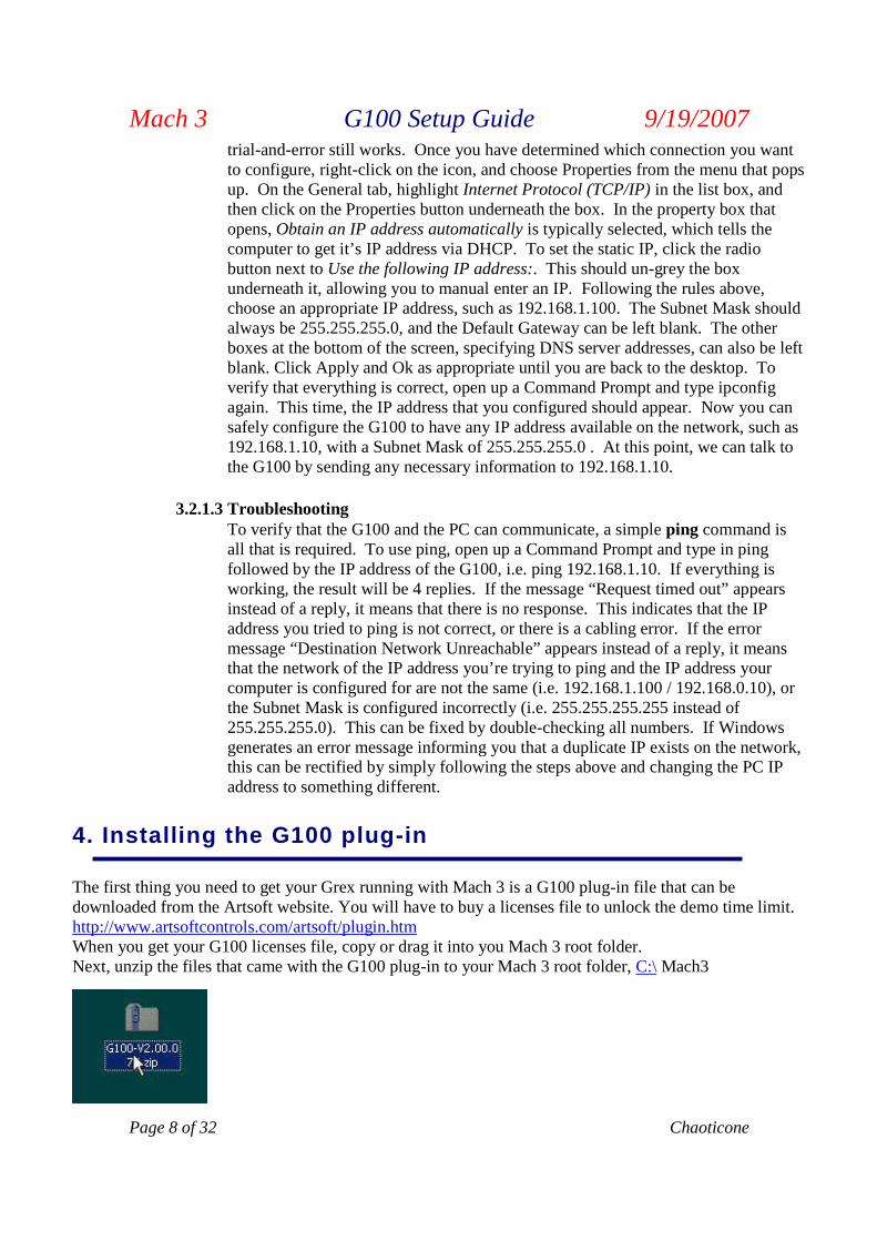
The first thing you need to get your Grex running with Mach 3 is a G100 plug-in file that can bedownloaded from the Artsoft website. You will have to buy a licenses file to unlock the demo time limit.http://www.artsoftcontrols.com/artsoft/plugin.htmWhen you get your G100 licenses file, copy or drag it into you Mach 3 root folder.Next, unzip the files that came with the G100 plug-in to your Mach 3 root folder, C:\ Mach3
Mach 3 G100 Setup Guide 9/19/2007
Chaoticone Page 9 of 32
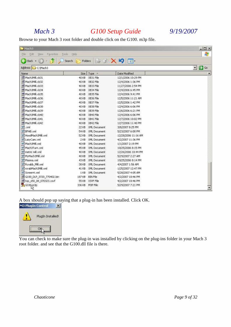
Browse to your Mach 3 root folder and double click on the G100. m3p file.
A box should pop up saying that a plug-in has been installed. Click OK.
You can check to make sure the plug-in was installed by clicking on the plug-ins folder in your Mach 3root folder. and see that the G100.dll file is there.
Mach 3 G100 Setup Guide 9/19/2007
Page 10 of 32 Chaoticone
5. Loading the firmware
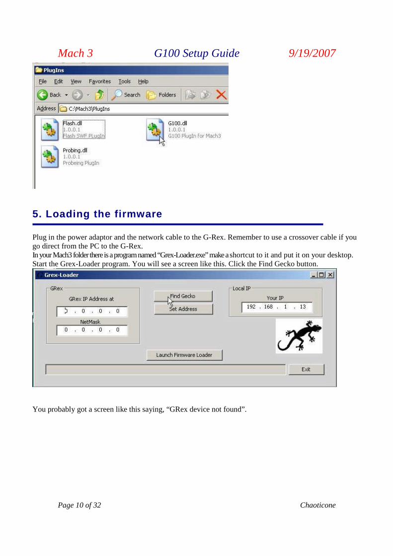
Plug in the power adaptor and the network cable to the G-Rex. Remember to use a crossover cable if yougo direct from the PC to the G-Rex.In yourMach3 folder thereis aprogramnamed “Grex-Loader.exe”makeashortcut to it and put it on your desktop.Start the Grex-Loader program. You will see a screen like this. Click the Find Gecko button.
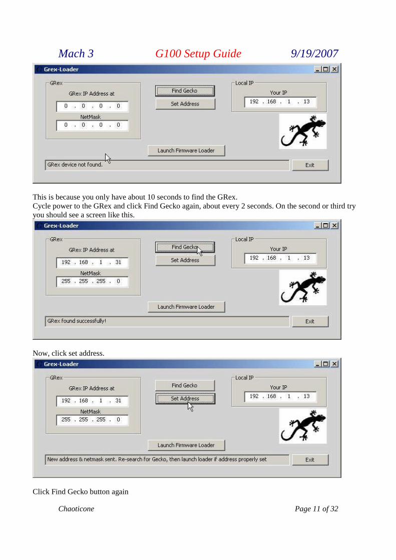
You probably got a screen like this saying, “GRex device not found”.
Mach 3 G100 Setup Guide 9/19/2007
Chaoticone Page 11 of 32
This is because you only have about 10 seconds to find the GRex.Cycle power to the GRex and click Find Gecko again, about every 2 seconds. On the second or third tryyou should see a screen like this.
Now, click set address.
Click Find Gecko button again
Mach 3 G100 Setup Guide 9/19/2007
Page 12 of 32 Chaoticone
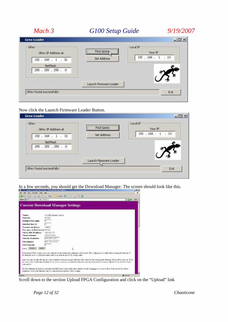
Now click the Launch Firmware Loader Button.
In a few seconds, you should get the Download Manager. The screen should look like this.
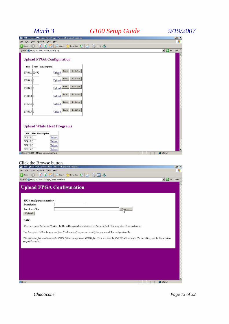
Scroll down to the section Upload FPGA Configuration and click on the “Upload” link
Mach 3 G100 Setup Guide 9/19/2007
Chaoticone Page 13 of 32
Click the Browse button.
Mach 3 G100 Setup Guide 9/19/2007
Page 14 of 32 Chaoticone
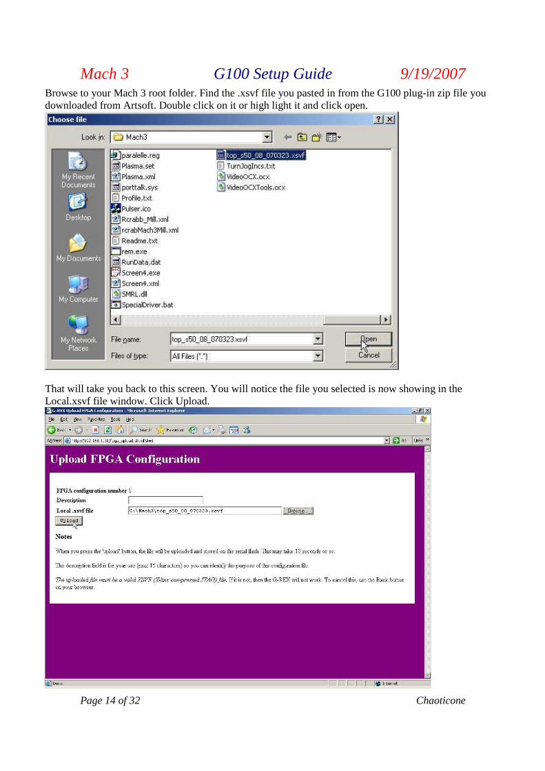
Browse to your Mach 3 root folder. Find the .xsvf file you pasted in from the G100 plug-in zip file youdownloaded from Artsoft. Double click on it or high light it and click open.
That will take you back to this screen. You will notice the file you selected is now showing in theLocal.xsvf file window. Click Upload.
Mach 3 G100 Setup Guide 9/19/2007
Chaoticone Page 15 of 32
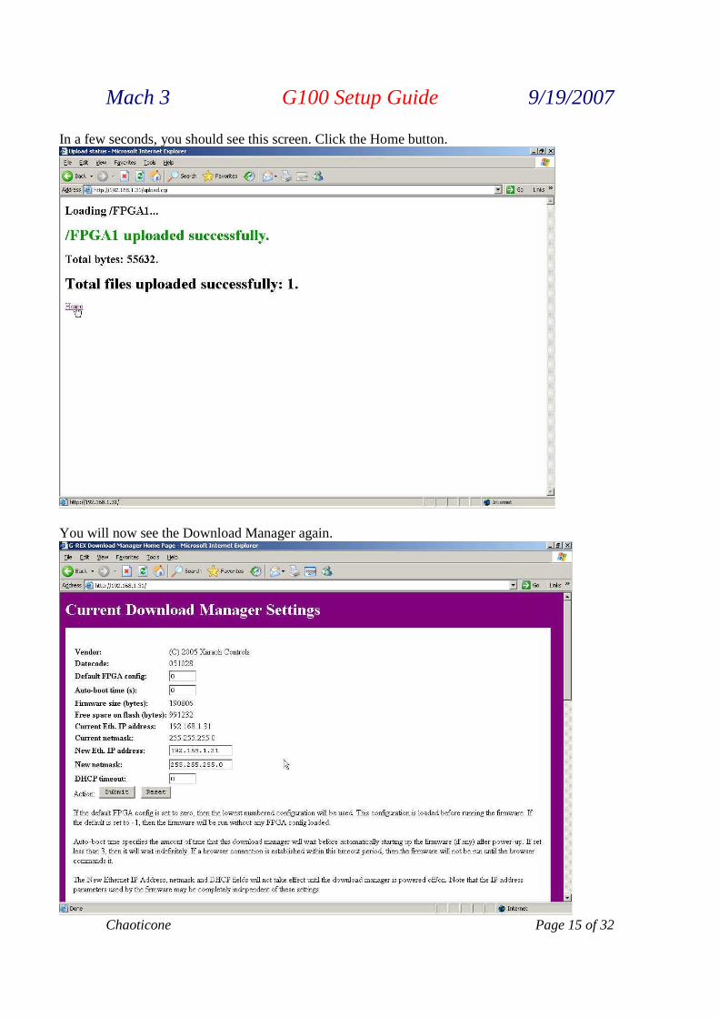
In a few seconds, you should see this screen. Click the Home button.
You will now see the Download Manager again.
Mach 3 G100 Setup Guide 9/19/2007
Page 16 of 32 Chaoticone
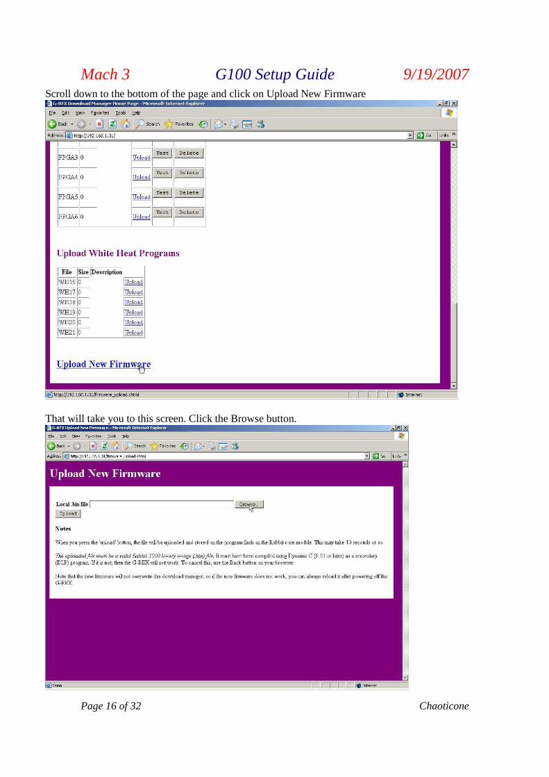
Scroll down to the bottom of the page and click on Upload New Firmware
That will take you to this screen. Click the Browse button.
Mach 3 G100 Setup Guide 9/19/2007
Chaoticone Page 17 of 32
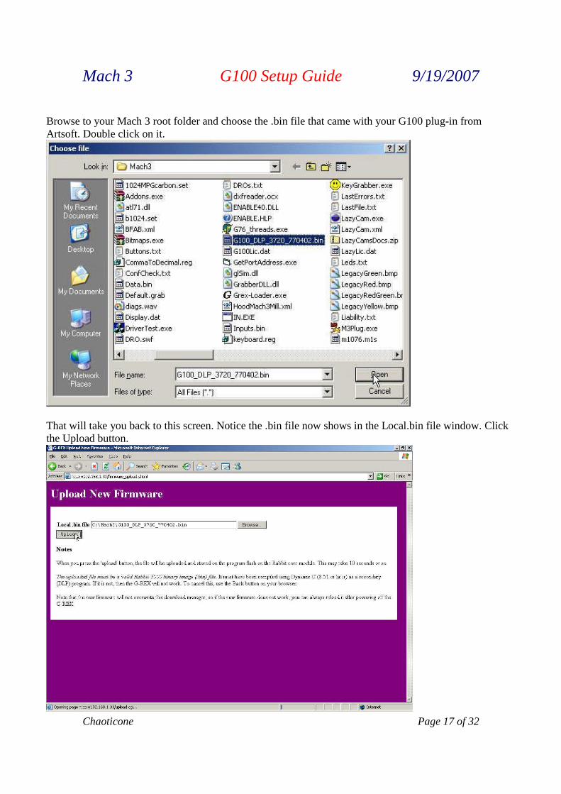
Browse to your Mach 3 root folder and choose the .bin file that came with your G100 plug-in fromArtsoft. Double click on it.
That will take you back to this screen. Notice the .bin file now shows in the Local.bin file window. Clickthe Upload button.

Mach 3 G100 Setup Guide 9/19/2007
Page 18 of 32 Chaoticone
In a few seconds you should see a screen like this. Click the home link.
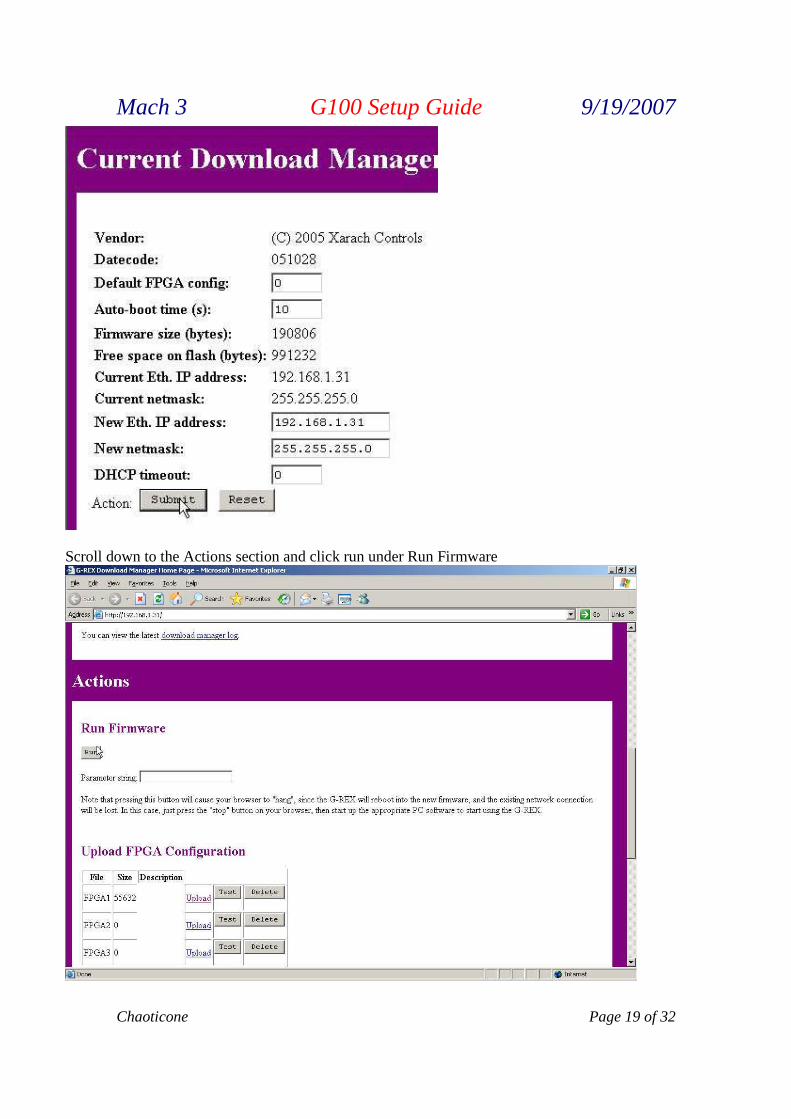
This brings you back to the Download Manager. Type 10 in the Auto-boot time window and press enter.
Now click the Submit button.
Mach 3 G100 Setup Guide 9/19/2007
Chaoticone Page 19 of 32
Scroll down to the Actions section and click run under Run Firmware
Mach 3 G100 Setup Guide 9/19/2007
Page 20 of 32 Chaoticone
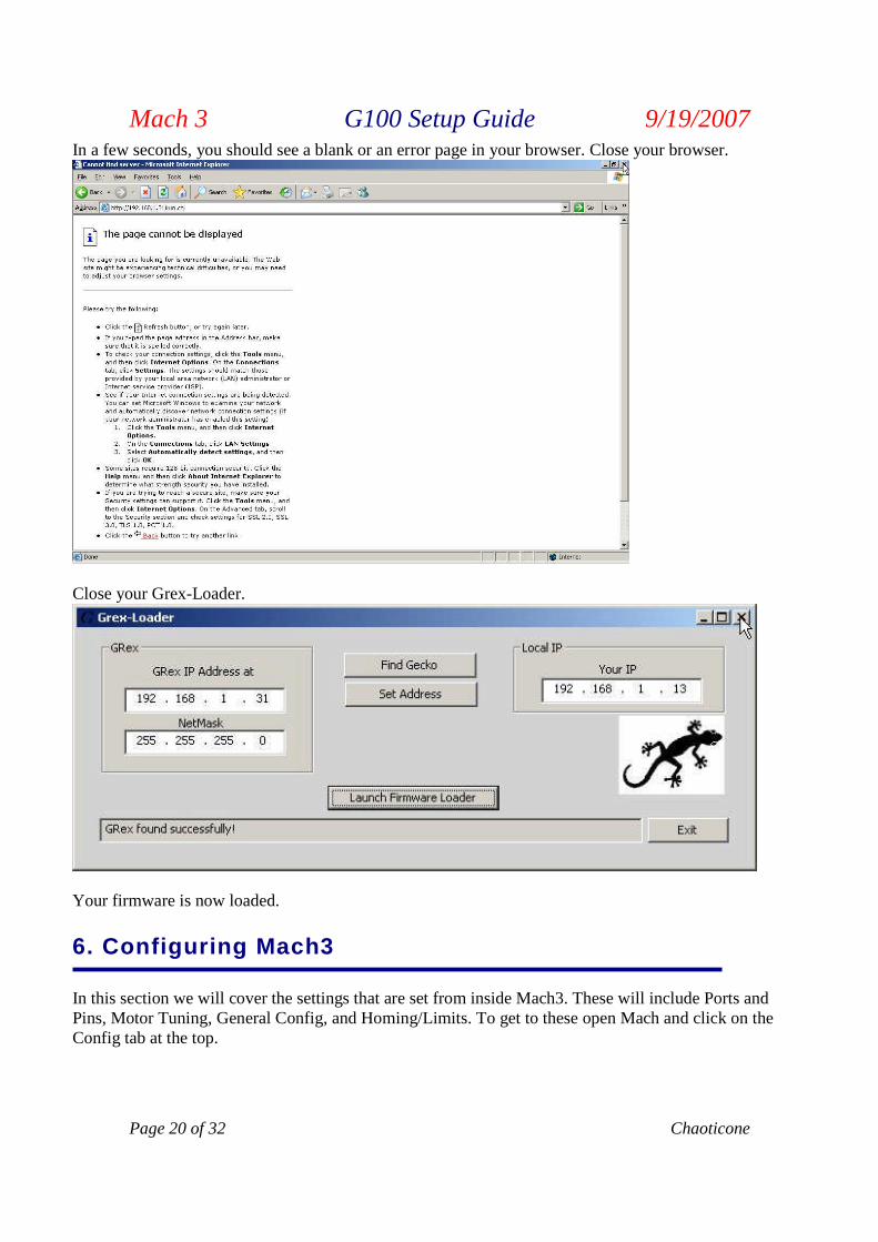
In a few seconds, you should see a blank or an error page in your browser. Close your browser.
Close your Grex-Loader.
Your firmware is now loaded.
6. Configuring Mach3
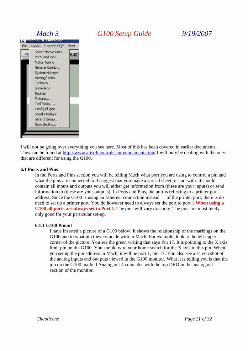
In this section we will cover the settings that are set from inside Mach3. These will include Ports andPins, Motor Tuning, General Config, and Homing/Limits. To get to these open Mach and click on theConfig tab at the top.
Mach 3 G100 Setup Guide 9/19/2007
Chaoticone Page 21 of 32
I will not be going over everything you see here. Most of this has been covered in earlier documents.They can be found at http://www.artsoftcontrols.com/documentation/ I will only be dealing with the onesthat are different for using the G100.
6.1 Ports and PinsIn the Ports and Pins section you will be telling Mach what port you are using to control a pin andwhat the pins are connected to. I suggest that you make a spread sheet to start with. It shouldcontain all inputs and outputs you will either get information from (these are your inputs) or sendinformation to (these are your outputs). In Ports and Pins, the port is referring to a printer portaddress. Since the G100 is using an Ethernet connection instead of the printer port, there is noneed to set up a printer port. You do however need to always set the port to port 1.When using aG100 all ports are always set to Port 1. The pins will vary drasticly. The pins are most likelyonly good for your particular set-up.
6.1.1 G100 PinoutI have inserted a picture of a G100 below. It shows the relationship of the markings on theG100 and to what pin they coincide with in Mach. For example, look at the left uppercorner of the picture. You see the green writing that says Pin 17. It is pointing to the X axislimit pin on the G100. You should wire your home switch for the X axis to this pin. Whenyou set up the pin address in Mach, it will be port 1, pin 17. You also see a screen shot ofthe analog inputs and out puts viewed in the G100 monitor. What it is telling you is that thepin on the G100 marked Analog out 4 coincides with the top DRO in the analog outsection of the monitor.

Mach 3 G100 Setup Guide 9/19/2007
Page 22 of 32 Chaoticone
Mach 3 G100 Setup Guide 9/19/2007
Chaoticone Page 23 of 32
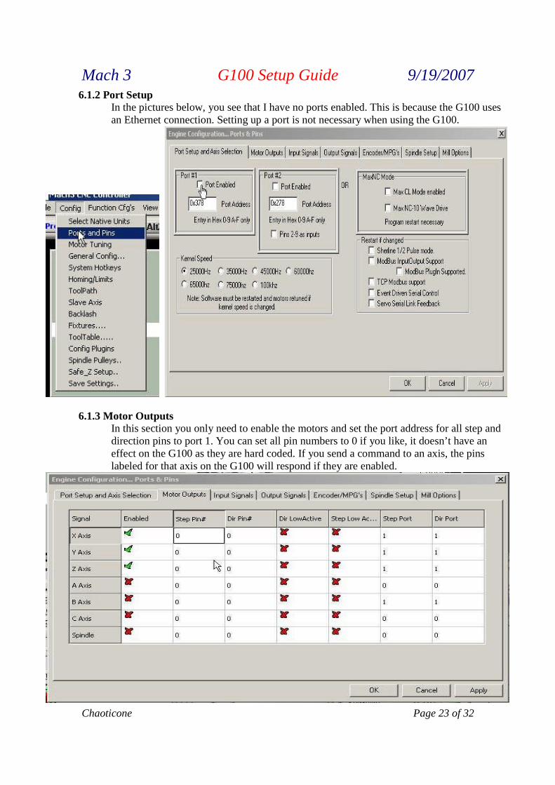
6.1.2 Port SetupIn the pictures below, you see that I have no ports enabled. This is because the G100 usesan Ethernet connection. Setting up a port is not necessary when using the G100.
6.1.3 Motor OutputsIn this section you only need to enable the motors and set the port address for all step anddirection pins to port 1. You can set all pin numbers to 0 if you like, it doesn’t have aneffect on the G100 as they are hard coded. If you send a command to an axis, the pinslabeled for that axis on the G100 will respond if they are enabled.
Mach 3 G100 Setup Guide 9/19/2007
Page 24 of 32 Chaoticone
6.1.4 Input SignalsInputs are signals you are sending information to Mach. There are several types of inputsignals the G100 and Mach can use to perform many functions. I will try to cover thefollowing in this section. Digital, Analog. Encoder, and MPG (Manual Pulse Generator).
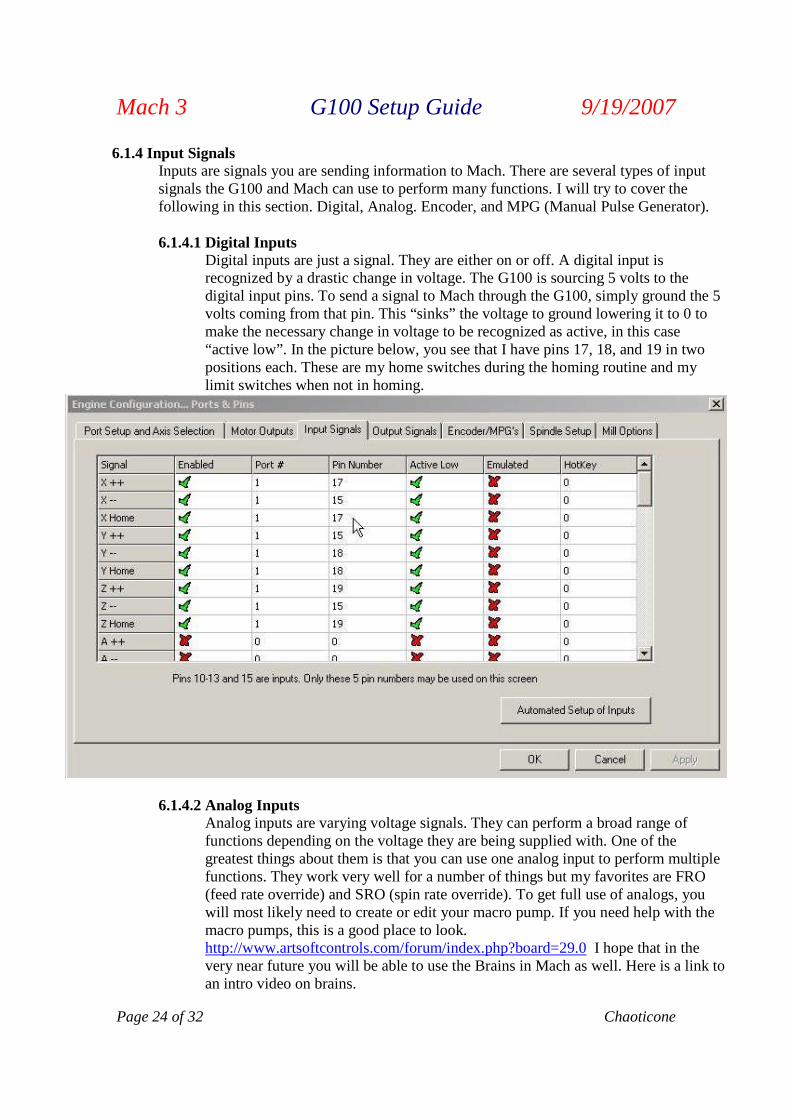
6.1.4.1 Digital InputsDigital inputs are just a signal. They are either on or off. A digital input isrecognized by a drastic change in voltage. The G100 is sourcing 5 volts to thedigital input pins. To send a signal to Mach through the G100, simply ground the 5volts coming from that pin. This “sinks” the voltage to ground lowering it to 0 tomake the necessary change in voltage to be recognized as active, in this case“active low”. In the picture below, you see that I have pins 17, 18, and 19 in twopositions each. These are my home switches during the homing routine and mylimit switches when not in homing.
6.1.4.2 Analog InputsAnalog inputs are varying voltage signals. They can perform a broad range offunctions depending on the voltage they are being supplied with. One of thegreatest things about them is that you can use one analog input to perform multiplefunctions. They work very well for a number of things but my favorites are FRO(feed rate override) and SRO (spin rate override). To get full use of analogs, youwill most likely need to create or edit your macro pump. If you need help with themacro pumps, this is a good place to look.http://www.artsoftcontrols.com/forum/index.php?board=29.0 I hope that in thevery near future you will be able to use the Brains in Mach as well. Here is a link toan intro video on brains.
Mach 3 G100 Setup Guide 9/19/2007
Chaoticone Page 25 of 32
http://www.artsoftcontrols.com/Videos/Mach3%20Video%20Selections/Mach3%20Video%20Selections.html I have attached an example macro pump that I use for my FRO.
'macropump.m1s MyGrexFeedOVPot=GetInput(124)FeedPercent=(FeedOVPot/32768)FeedOver=(300*FeedPercent)SetOEMDRO(821,FeedOver)FeedOver=10+(190*FeedPercent)
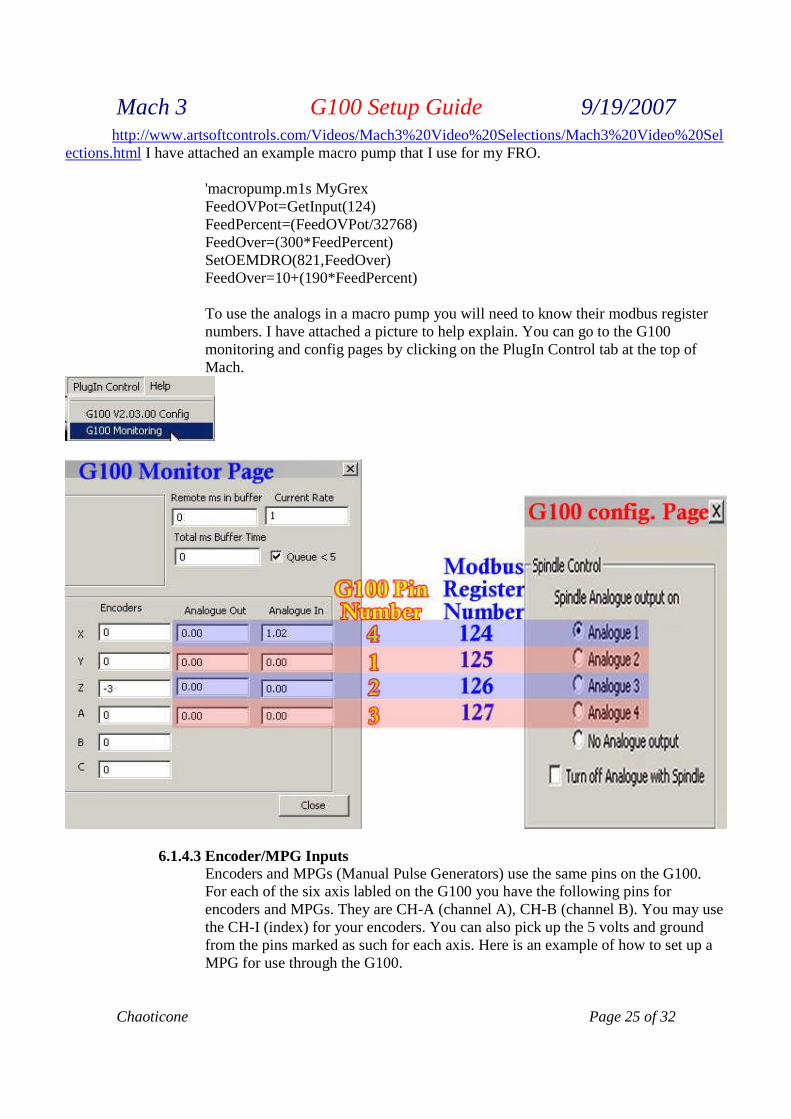
To use the analogs in a macro pump you will need to know their modbus registernumbers. I have attached a picture to help explain. You can go to the G100monitoring and config pages by clicking on the PlugIn Control tab at the top ofMach.
6.1.4.3 Encoder/MPG InputsEncoders and MPGs (Manual Pulse Generators) use the same pins on the G100.For each of the six axis labled on the G100 you have the following pins forencoders and MPGs. They are CH-A (channel A), CH-B (channel B). You may usethe CH-I (index) for your encoders. You can also pick up the 5 volts and groundfrom the pins marked as such for each axis. Here is an example of how to set up aMPG for use through the G100.
Mach 3 G100 Setup Guide 9/19/2007
Page 26 of 32 Chaoticone
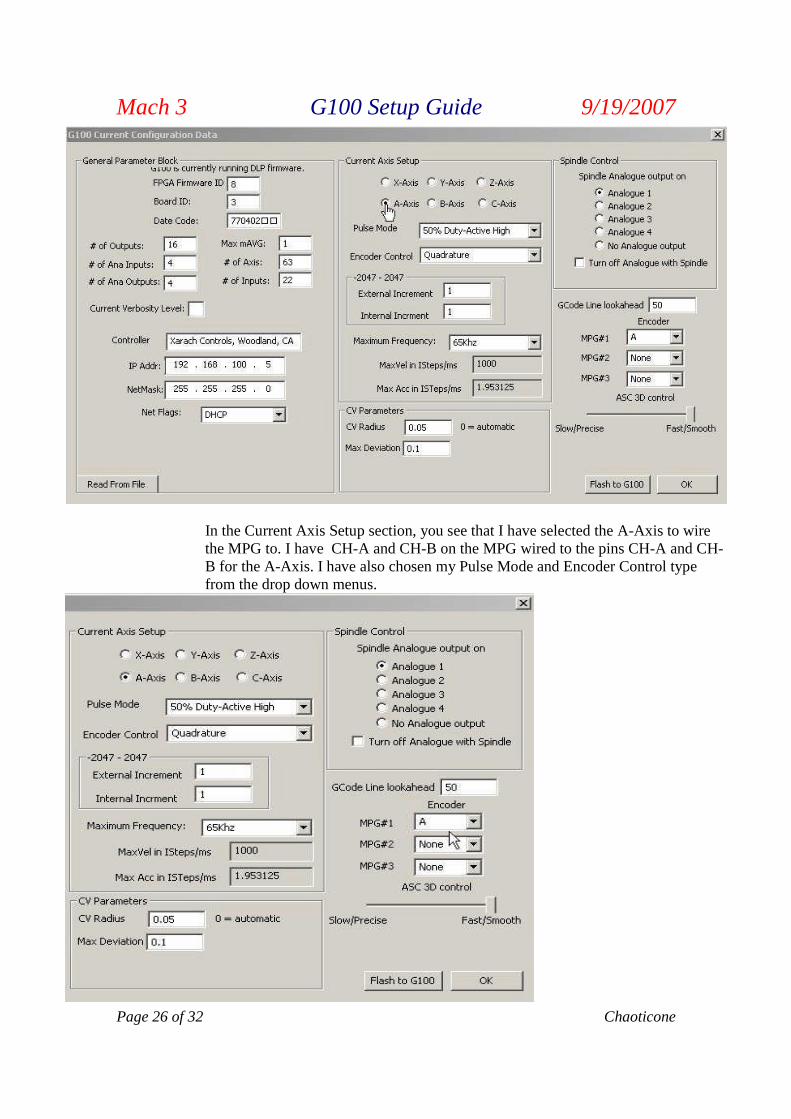
In the Current Axis Setup section, you see that I have selected the A-Axis to wirethe MPG to. I have CH-A and CH-B on the MPG wired to the pins CH-A and CH-B for the A-Axis. I have also chosen my Pulse Mode and Encoder Control typefrom the drop down menus.
Mach 3 G100 Setup Guide 9/19/2007
Chaoticone Page 27 of 32
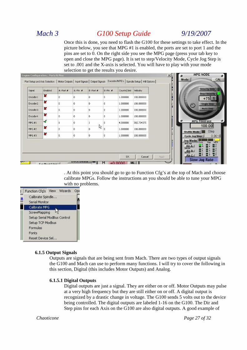
Once this is done, you need to flash the G100 for these settings to take effect. In thepicture below, you see that MPG #1 is enabled, the ports are set to port 1 and thepins are set to 0. On the right side you see the MPG page (press your tab key toopen and close the MPG page). It is set to step/Velocity Mode, Cycle Jog Step isset to .001 and the X-axis is selected. You will have to play with your modeselection to get the results you desire.
. At this point you should go to go to Function Cfg’s at the top of Mach and choosecalibrate MPGs. Follow the instructions an you should be able to tune your MPGwith no problems.
6.1.5 Output SignalsOutputs are signals that are being sent from Mach. There are two types of output signalsthe G100 and Mach can use to perform many functions. I will try to cover the following inthis section, Digital (this includes Motor Outputs) and Analog.
6.1.5.1 Digital OutputsDigital outputs are just a signal. They are either on or off. Motor Outputs may pulseat a very high frequency but they are still either on or off. A digital output isrecognized by a drastic change in voltage. The G100 sends 5 volts out to the devicebeing controlled. The digital outputs are labeled 1-16 on the G100. The Dir andStep pins for each Axis on the G100 are also digital outputs. A good example of
Mach 3 G100 Setup Guide 9/19/2007
Page 28 of 32 Chaoticone
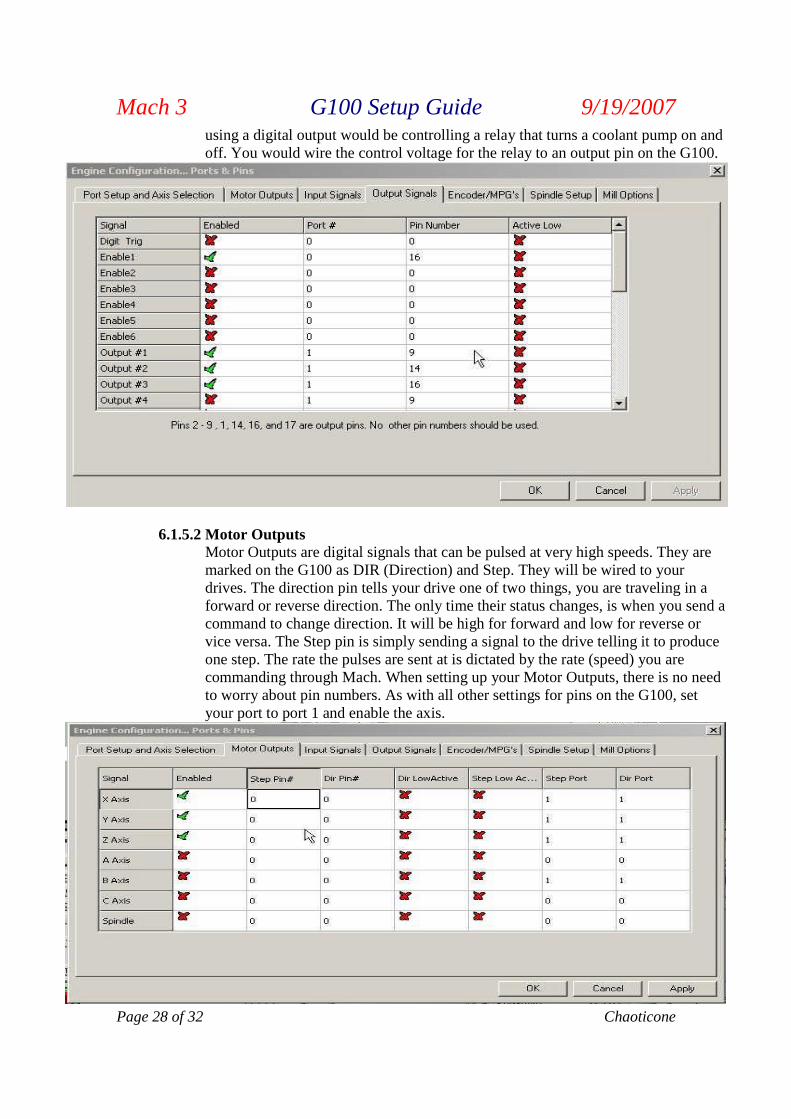
using a digital output would be controlling a relay that turns a coolant pump on andoff. You would wire the control voltage for the relay to an output pin on the G100.
6.1.5.2 Motor OutputsMotor Outputs are digital signals that can be pulsed at very high speeds. They aremarked on the G100 as DIR (Direction) and Step. They will be wired to yourdrives. The direction pin tells your drive one of two things, you are traveling in aforward or reverse direction. The only time their status changes, is when you send acommand to change direction. It will be high for forward and low for reverse orvice versa. The Step pin is simply sending a signal to the drive telling it to produceone step. The rate the pulses are sent at is dictated by the rate (speed) you arecommanding through Mach. When setting up your Motor Outputs, there is no needto worry about pin numbers. As with all other settings for pins on the G100, setyour port to port 1 and enable the axis.
Mach 3 G100 Setup Guide 9/19/2007
Chaoticone Page 29 of 32
6.1.5.3 Analog OutputsAnalog outputs are varying voltage signals. A good example of a device using ananalog output from Mach is a VFD (Variable Frequency Drive) At present, ananalog output for a VFD is very simple to set up. This is covered in the very nextsection. Other analog outputs will need to be controlled using the macropump. Formore information on the Analogs and macropumps, refer back to section 6.1.4.2,Analog Inputs
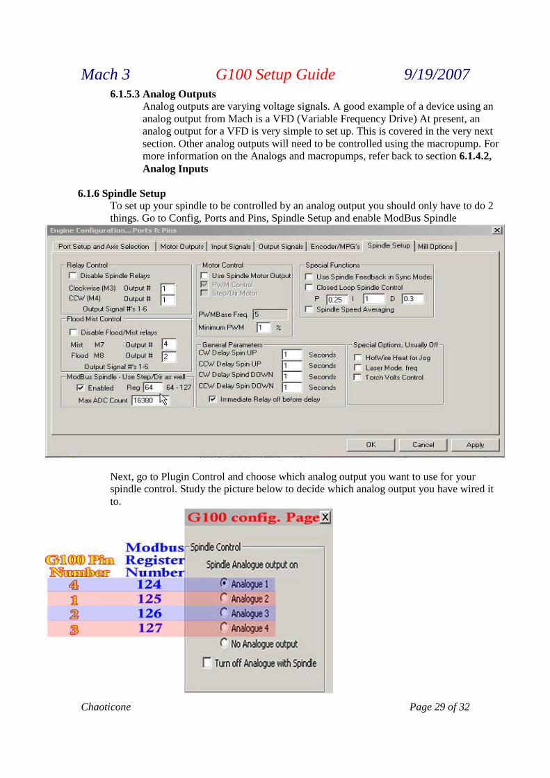
6.1.6 Spindle SetupTo set up your spindle to be controlled by an analog output you should only have to do 2things. Go to Config, Ports and Pins, Spindle Setup and enable ModBus Spindle
Next, go to Plugin Control and choose which analog output you want to use for yourspindle control. Study the picture below to decide which analog output you have wired itto.
Mach 3 G100 Setup Guide 9/19/2007
Page 30 of 32 Chaoticone
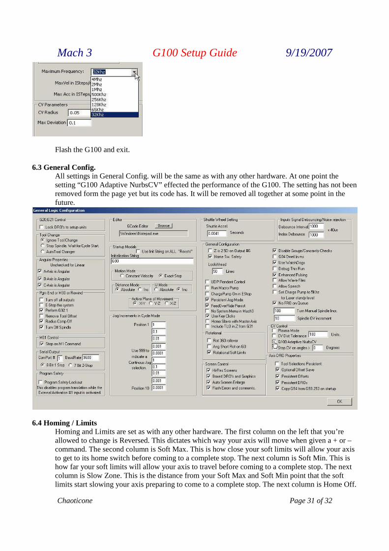
Flash the G100 and exit.6.2 Motor tuning
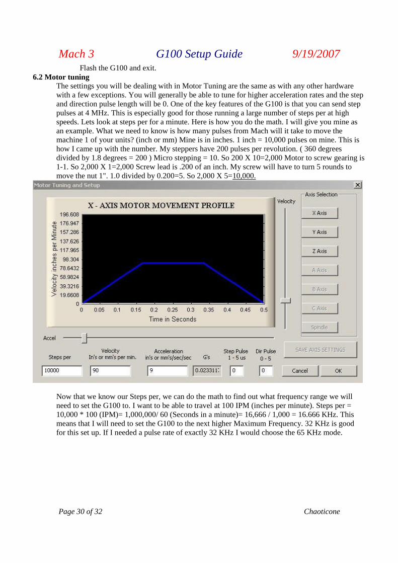
The settings you will be dealing with in Motor Tuning are the same as with any other hardwarewith a few exceptions. You will generally be able to tune for higher acceleration rates and the stepand direction pulse length will be 0. One of the key features of the G100 is that you can send steppulses at 4 MHz. This is especially good for those running a large number of steps per at highspeeds. Lets look at steps per for a minute. Here is how you do the math. I will give you mine asan example. What we need to know is how many pulses from Mach will it take to move themachine 1 of your units? (inch or mm) Mine is in inches. 1 inch = 10,000 pulses on mine. This ishow I came up with the number. My steppers have 200 pulses per revolution. ( 360 degreesdivided by 1.8 degrees = 200 ) Micro stepping = 10. So 200 X 10=2,000 Motor to screw gearing is1-1. So 2,000 X 1=2,000 Screw lead is .200 of an inch. My screw will have to turn 5 rounds tomove the nut 1". 1.0 divided by 0.200=5. So 2,000 X 5=10,000.
Now that we know our Steps per, we can do the math to find out what frequency range we willneed to set the G100 to. I want to be able to travel at 100 IPM (inches per minute). Steps per =10,000 * 100 (IPM)= 1,000,000/ 60 (Seconds in a minute)= 16,666 / 1,000 = 16.666 KHz. Thismeans that I will need to set the G100 to the next higher Maximum Frequency. 32 KHz is goodfor this set up. If I needed a pulse rate of exactly 32 KHz I would choose the 65 KHz mode.
Mach 3 G100 Setup Guide 9/19/2007
Chaoticone Page 31 of 32
Flash the G100 and exit.
6.3 General Config.All settings in General Config. will be the same as with any other hardware. At one point thesetting “G100 Adaptive NurbsCV” effected the performance of the G100. The setting has not beenremoved form the page yet but its code has. It will be removed all together at some point in thefuture.
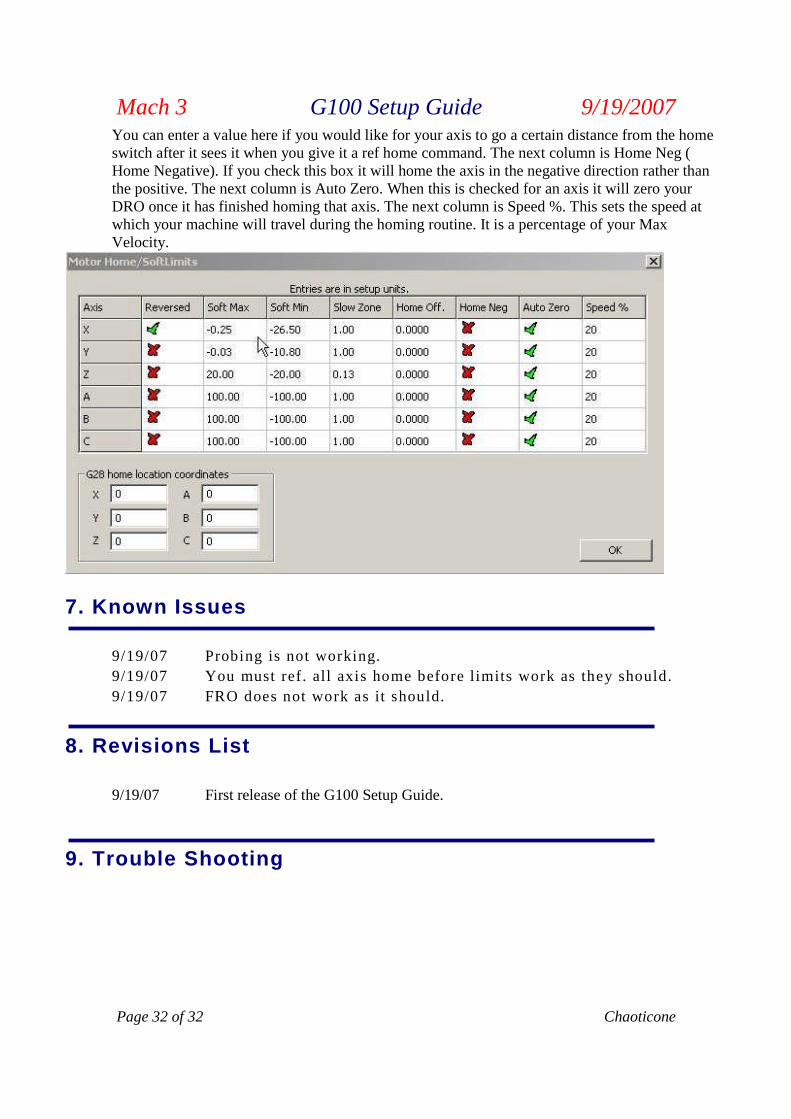
6.4 Homing / LimitsHoming and Limits are set as with any other hardware. The first column on the left that you’reallowed to change is Reversed. This dictates which way your axis will move when given a + or –command. The second column is Soft Max. This is how close your soft limits will allow your axisto get to its home switch before coming to a complete stop. The next column is Soft Min. This ishow far your soft limits will allow your axis to travel before coming to a complete stop. The nextcolumn is Slow Zone. This is the distance from your Soft Max and Soft Min point that the softlimits start slowing your axis preparing to come to a complete stop. The next column is Home Off.
Mach 3 G100 Setup Guide 9/19/2007
Page 32 of 32 Chaoticone
You can enter a value here if you would like for your axis to go a certain distance from the homeswitch after it sees it when you give it a ref home command. The next column is Home Neg (Home Negative). If you check this box it will home the axis in the negative direction rather thanthe positive. The next column is Auto Zero. When this is checked for an axis it will zero yourDRO once it has finished homing that axis. The next column is Speed %. This sets the speed atwhich your machine will travel during the homing routine. It is a percentage of your MaxVelocity.
7. Known Issues
9/19/07 Probing is not working.
9/19/07 You must ref. all axis home before limits work as they should.
9/19/07 FRO does not work as it should.
8. Revisions List
9/19/07 First release of the G100 Setup Guide.
9. Trouble Shooting

Special thanks to:
Art FenertyBrian BarkerCandaceChadChris BuchananGraham WaterworthHoodJohn PrenticeMariss FreimanisMontyPoppabearScott N.Steve HardyYnnebZealousAnd all others that have helped.