Embed Size (px)
DESCRIPTION
Repair laptops
Citation preview
MacBook Pro 15" Core 2 Duo
Models A1226 and A1260 Logic
Board ReplacementWritten By: Walter Galan
TOOLS:
Arctic Silver ArctiClean (1)Arctic Silver Thermal Paste (1)Phillips 00 Screwdriver (1)Spudger (1)T6 Torx Screwdriver (1)
PARTS:
MacBook Pro 15" (Model A1226) 2.2GHz Logic Board (1)MacBook Pro 15" (Model A1226) 2.4GHz Logic Board (1)MacBook Pro 15" (Model A1260) 2.4GHz Logic Board (1)MacBook Pro 15" (Model A1260) 2.5GHz Logic Board (1)
SUMMARY
This guide will walk you through how to replace a faulty logic board. This motherboardincludes all the ports on the right side of the MacBook Pro.
MacBook Pro 15" Core 2 Duo Models A1226 and A1260 Logic Board Replacement
© iFixit — CC BY-NC-SA www.iFixit.com Page 1 of 15

Step 1 — Battery
Use your fingers to push both battery release tabs away from the battery, and lift thebattery out of the computer.
Step 2 — RAM Shield
Remove the three identical 2mm Phillips screws from the memory door.
Lift the memory door up enough to grip it and slide it toward you, pulling it away from thecasing.
MacBook Pro 15" Core 2 Duo Models A1226 and A1260 Logic Board Replacement
© iFixit — CC BY-NC-SA www.iFixit.com Page 2 of 15
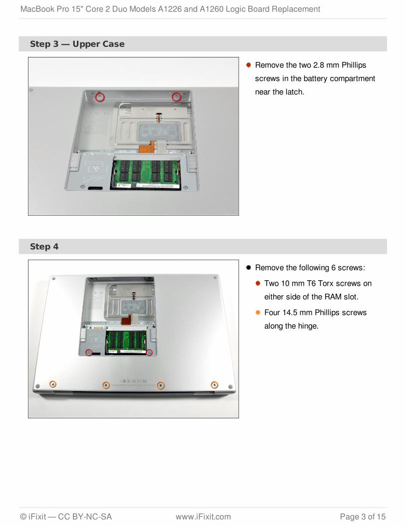
Step 3 — Upper Case
Remove the two 2.8 mm Phillipsscrews in the battery compartmentnear the latch.
Step 4
Remove the following 6 screws:
Two 10 mm T6 Torx screws oneither side of the RAM slot.
Four 14.5 mm Phillips screwsalong the hinge.
MacBook Pro 15" Core 2 Duo Models A1226 and A1260 Logic Board Replacement
© iFixit — CC BY-NC-SA www.iFixit.com Page 3 of 15
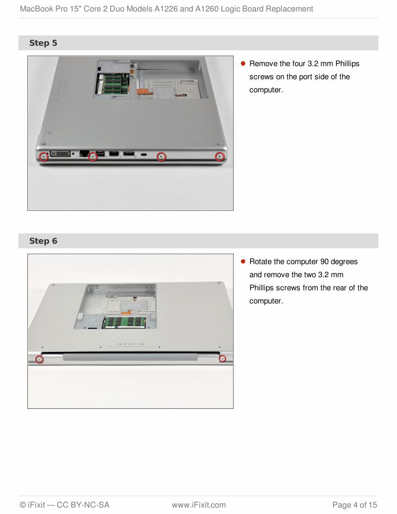
Step 5
Remove the four 3.2 mm Phillipsscrews on the port side of thecomputer.
Step 6
Rotate the computer 90 degreesand remove the two 3.2 mmPhillips screws from the rear of thecomputer.
MacBook Pro 15" Core 2 Duo Models A1226 and A1260 Logic Board Replacement
© iFixit — CC BY-NC-SA www.iFixit.com Page 4 of 15
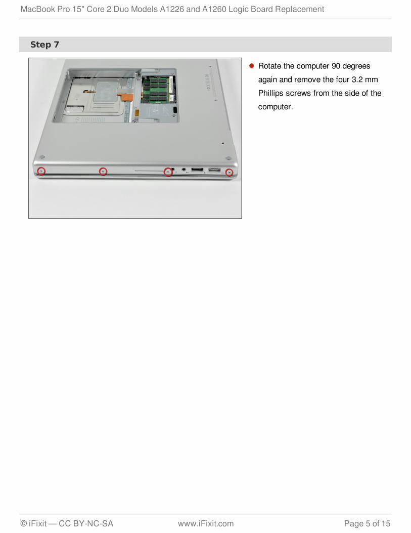
Step 7
Rotate the computer 90 degreesagain and remove the four 3.2 mmPhillips screws from the side of thecomputer.
MacBook Pro 15" Core 2 Duo Models A1226 and A1260 Logic Board Replacement
© iFixit — CC BY-NC-SA www.iFixit.com Page 5 of 15
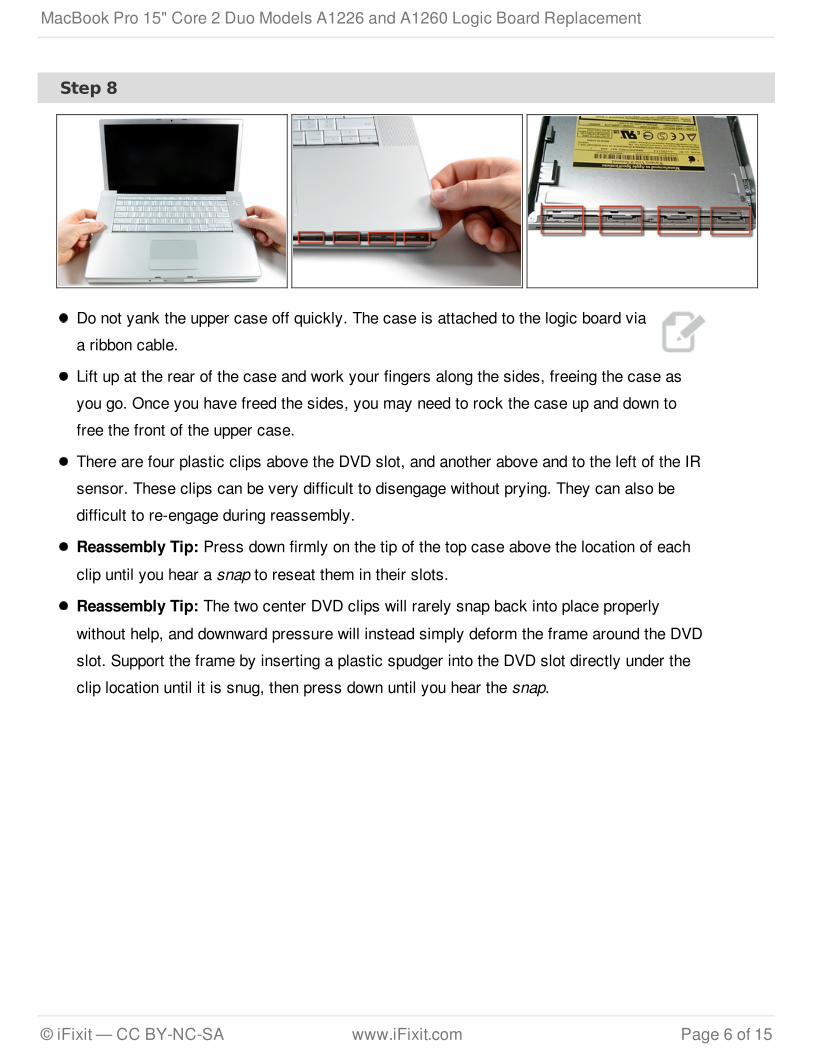
Step 8
Do not yank the upper case off quickly. The case is attached to the logic board viaa ribbon cable.
Lift up at the rear of the case and work your fingers along the sides, freeing the case asyou go. Once you have freed the sides, you may need to rock the case up and down tofree the front of the upper case.
There are four plastic clips above the DVD slot, and another above and to the left of the IRsensor. These clips can be very difficult to disengage without prying. They can also bedifficult to re-engage during reassembly.
Reassembly Tip: Press down firmly on the tip of the top case above the location of eachclip until you hear a snap to reseat them in their slots.
Reassembly Tip: The two center DVD clips will rarely snap back into place properlywithout help, and downward pressure will instead simply deform the frame around the DVDslot. Support the frame by inserting a plastic spudger into the DVD slot directly under theclip location until it is snug, then press down until you hear the snap.
MacBook Pro 15" Core 2 Duo Models A1226 and A1260 Logic Board Replacement
© iFixit — CC BY-NC-SA www.iFixit.com Page 6 of 15
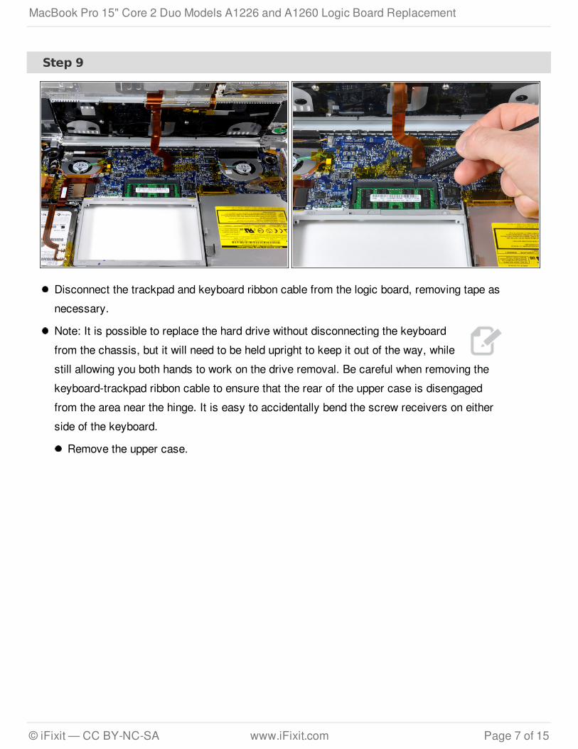
Step 9
Disconnect the trackpad and keyboard ribbon cable from the logic board, removing tape asnecessary.
Note: It is possible to replace the hard drive without disconnecting the keyboardfrom the chassis, but it will need to be held upright to keep it out of the way, whilestill allowing you both hands to work on the drive removal. Be careful when removing thekeyboard-trackpad ribbon cable to ensure that the rear of the upper case is disengagedfrom the area near the hinge. It is easy to accidentally bend the screw receivers on eitherside of the keyboard.
Remove the upper case.
MacBook Pro 15" Core 2 Duo Models A1226 and A1260 Logic Board Replacement
© iFixit — CC BY-NC-SA www.iFixit.com Page 7 of 15
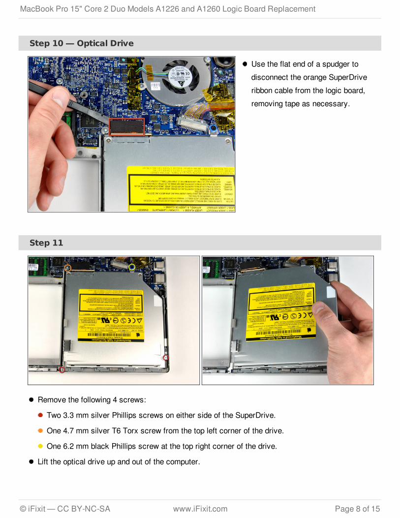
Step 10 — Optical Drive
Use the flat end of a spudger todisconnect the orange SuperDriveribbon cable from the logic board,removing tape as necessary.
Step 11
Remove the following 4 screws:
Two 3.3 mm silver Phillips screws on either side of the SuperDrive.
One 4.7 mm silver T6 Torx screw from the top left corner of the drive.
One 6.2 mm black Phillips screw at the top right corner of the drive.
Lift the optical drive up and out of the computer.
MacBook Pro 15" Core 2 Duo Models A1226 and A1260 Logic Board Replacement
© iFixit — CC BY-NC-SA www.iFixit.com Page 8 of 15
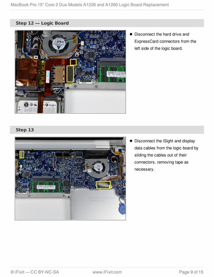
Step 12 — Logic Board
Disconnect the hard drive andExpressCard connectors from theleft side of the logic board.
Step 13
Disconnect the iSight and displaydata cables from the logic board bysliding the cables out of theirconnectors, removing tape asnecessary.
MacBook Pro 15" Core 2 Duo Models A1226 and A1260 Logic Board Replacement
© iFixit — CC BY-NC-SA www.iFixit.com Page 9 of 15
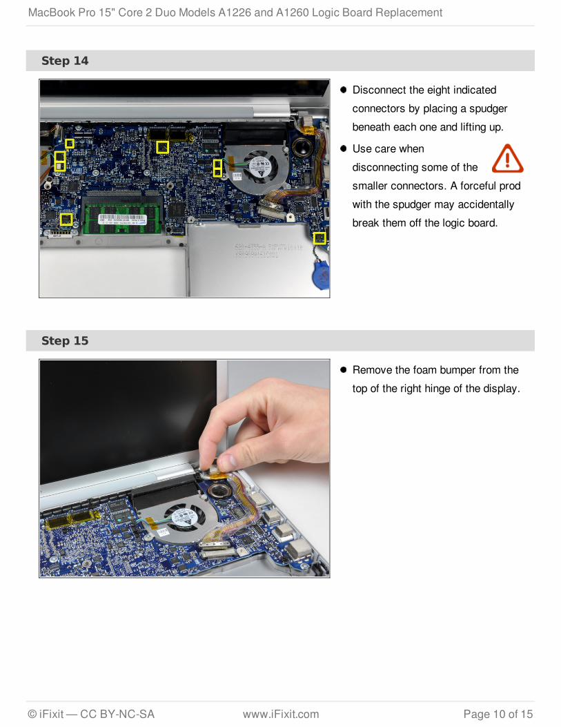
Step 14
Disconnect the eight indicatedconnectors by placing a spudgerbeneath each one and lifting up.
Use care whendisconnecting some of thesmaller connectors. A forceful prodwith the spudger may accidentallybreak them off the logic board.
Step 15
Remove the foam bumper from thetop of the right hinge of the display.
MacBook Pro 15" Core 2 Duo Models A1226 and A1260 Logic Board Replacement
© iFixit — CC BY-NC-SA www.iFixit.com Page 10 of 15

Step 16
Remove the silver 9.5 mm T6 Torxscrew securing the ground loop inthe display data cable to thecasing.
Step 17
Remove the single black 6 mm T6Torx screw securing the upperportion of the logic board to theupper case.
MacBook Pro 15" Core 2 Duo Models A1226 and A1260 Logic Board Replacement
© iFixit — CC BY-NC-SA www.iFixit.com Page 11 of 15
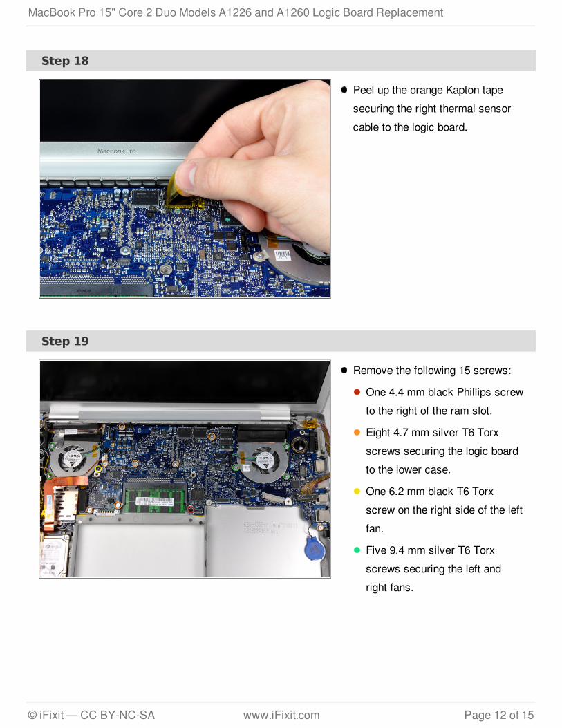
Step 18
Peel up the orange Kapton tapesecuring the right thermal sensorcable to the logic board.
Step 19
Remove the following 15 screws:
One 4.4 mm black Phillips screwto the right of the ram slot.
Eight 4.7 mm silver T6 Torxscrews securing the logic boardto the lower case.
One 6.2 mm black T6 Torxscrew on the right side of the leftfan.
Five 9.4 mm silver T6 Torxscrews securing the left andright fans.
MacBook Pro 15" Core 2 Duo Models A1226 and A1260 Logic Board Replacement
© iFixit — CC BY-NC-SA www.iFixit.com Page 12 of 15
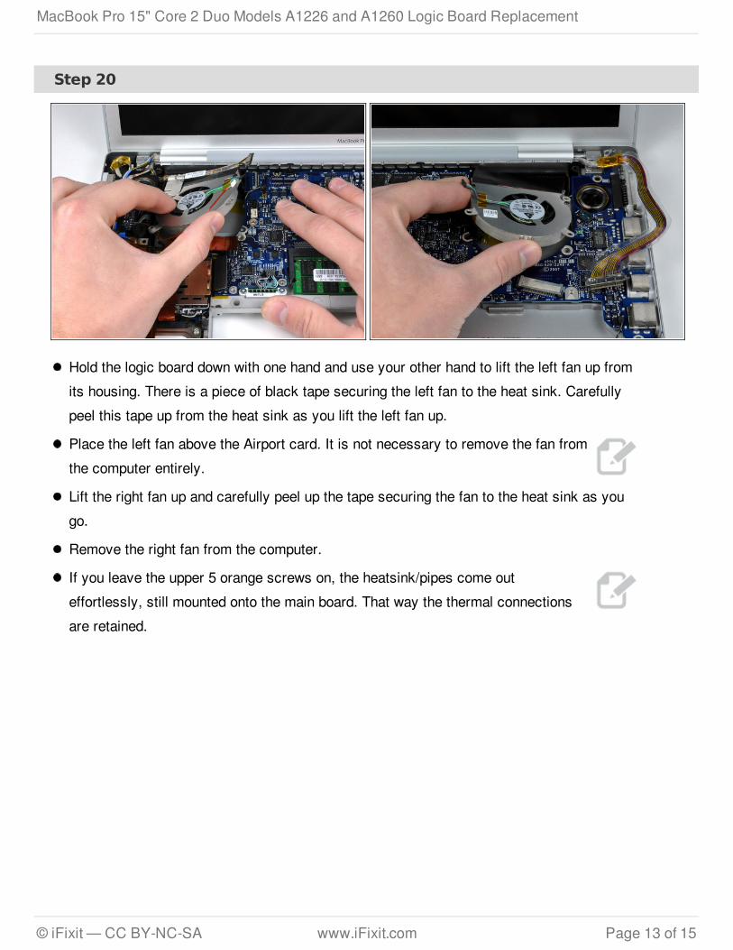
Step 20
Hold the logic board down with one hand and use your other hand to lift the left fan up fromits housing. There is a piece of black tape securing the left fan to the heat sink. Carefullypeel this tape up from the heat sink as you lift the left fan up.
Place the left fan above the Airport card. It is not necessary to remove the fan fromthe computer entirely.
Lift the right fan up and carefully peel up the tape securing the fan to the heat sink as yougo.
Remove the right fan from the computer.
If you leave the upper 5 orange screws on, the heatsink/pipes come outeffortlessly, still mounted onto the main board. That way the thermal connectionsare retained.
MacBook Pro 15" Core 2 Duo Models A1226 and A1260 Logic Board Replacement
© iFixit — CC BY-NC-SA www.iFixit.com Page 13 of 15
Step 21
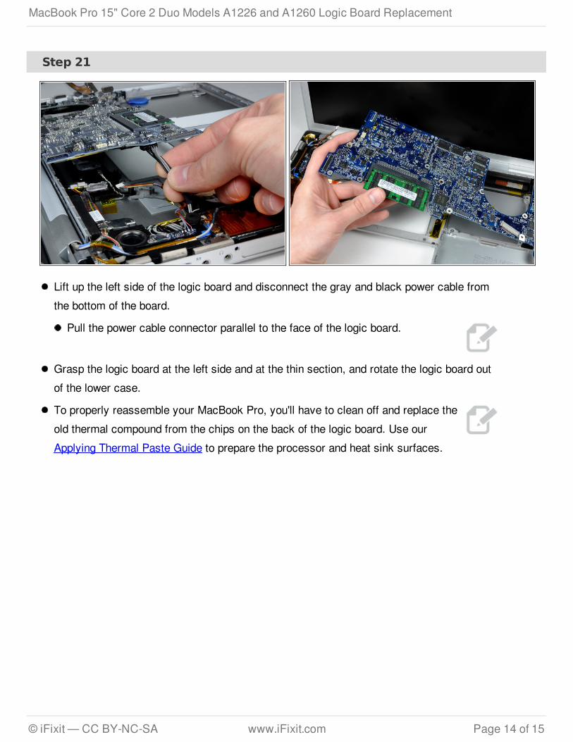
Lift up the left side of the logic board and disconnect the gray and black power cable fromthe bottom of the board.
Pull the power cable connector parallel to the face of the logic board.
Grasp the logic board at the left side and at the thin section, and rotate the logic board outof the lower case.
To properly reassemble your MacBook Pro, you'll have to clean off and replace theold thermal compound from the chips on the back of the logic board. Use ourApplying Thermal Paste Guide to prepare the processor and heat sink surfaces.
MacBook Pro 15" Core 2 Duo Models A1226 and A1260 Logic Board Replacement
© iFixit — CC BY-NC-SA www.iFixit.com Page 14 of 15

To reassemble your device, follow these instructions in reverse order.
This document was last generated on 2013-02-27 05:54:02 PM.
Step 22 — Logic Board Replacement
Release the tabs on each side ofthe RAM chip at the same time.These tabs lock the chip in placeand releasing them will cause thechip to "pop" up.
Pull the chip directly out from itsconnector.
If there are two RAM chipsinstalled, repeat the aboveprocedure for the second chip.
When reinstalling the logicboard, be sure to install anew layer of thermal paste on thethree processors. We have a guidethat makes it easy.
MacBook Pro 15" Core 2 Duo Models A1226 and A1260 Logic Board Replacement
© iFixit — CC BY-NC-SA www.iFixit.com Page 15 of 15