Embed Size (px)
Citation preview
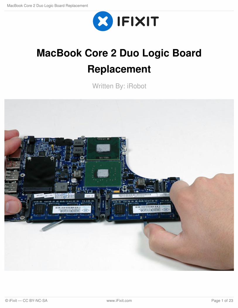
MacBook Core 2 Duo Logic BoardReplacement
Written By: iRobot
MacBook Core 2 Duo Logic Board Replacement
© iFixit — CC BY-NC-SA www.iFixit.com Page 1 of 23
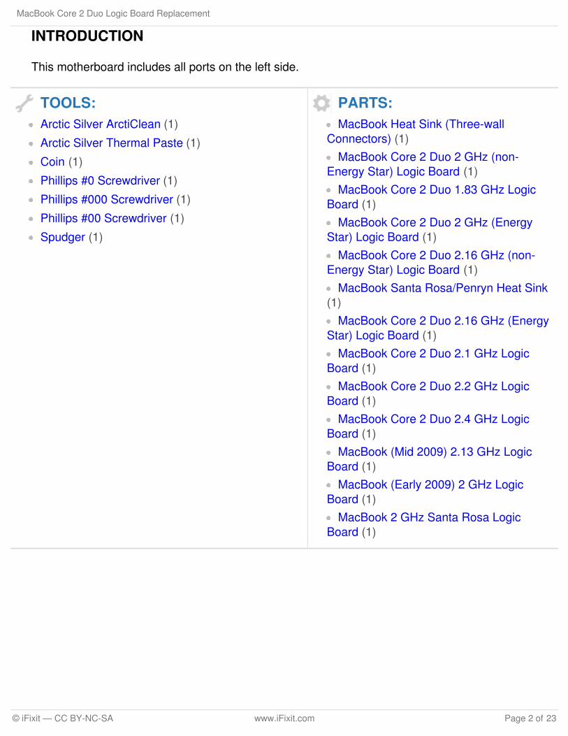
INTRODUCTION
This motherboard includes all ports on the left side.
TOOLS:Arctic Silver ArctiClean (1)
Arctic Silver Thermal Paste (1)
Coin (1)
Phillips #0 Screwdriver (1)
Phillips #000 Screwdriver (1)
Phillips #00 Screwdriver (1)
Spudger (1)
PARTS:MacBook Heat Sink (Three-wall
Connectors) (1)MacBook Core 2 Duo 2 GHz (non-
Energy Star) Logic Board (1)MacBook Core 2 Duo 1.83 GHz Logic
Board (1)MacBook Core 2 Duo 2 GHz (Energy
Star) Logic Board (1)MacBook Core 2 Duo 2.16 GHz (non-
Energy Star) Logic Board (1)MacBook Santa Rosa/Penryn Heat Sink
(1)MacBook Core 2 Duo 2.16 GHz (Energy
Star) Logic Board (1)MacBook Core 2 Duo 2.1 GHz Logic
Board (1)MacBook Core 2 Duo 2.2 GHz Logic
Board (1)MacBook Core 2 Duo 2.4 GHz Logic
Board (1)MacBook (Mid 2009) 2.13 GHz Logic
Board (1)MacBook (Early 2009) 2 GHz Logic
Board (1)MacBook 2 GHz Santa Rosa Logic
Board (1)
MacBook Core 2 Duo Logic Board Replacement
© iFixit — CC BY-NC-SA www.iFixit.com Page 2 of 23
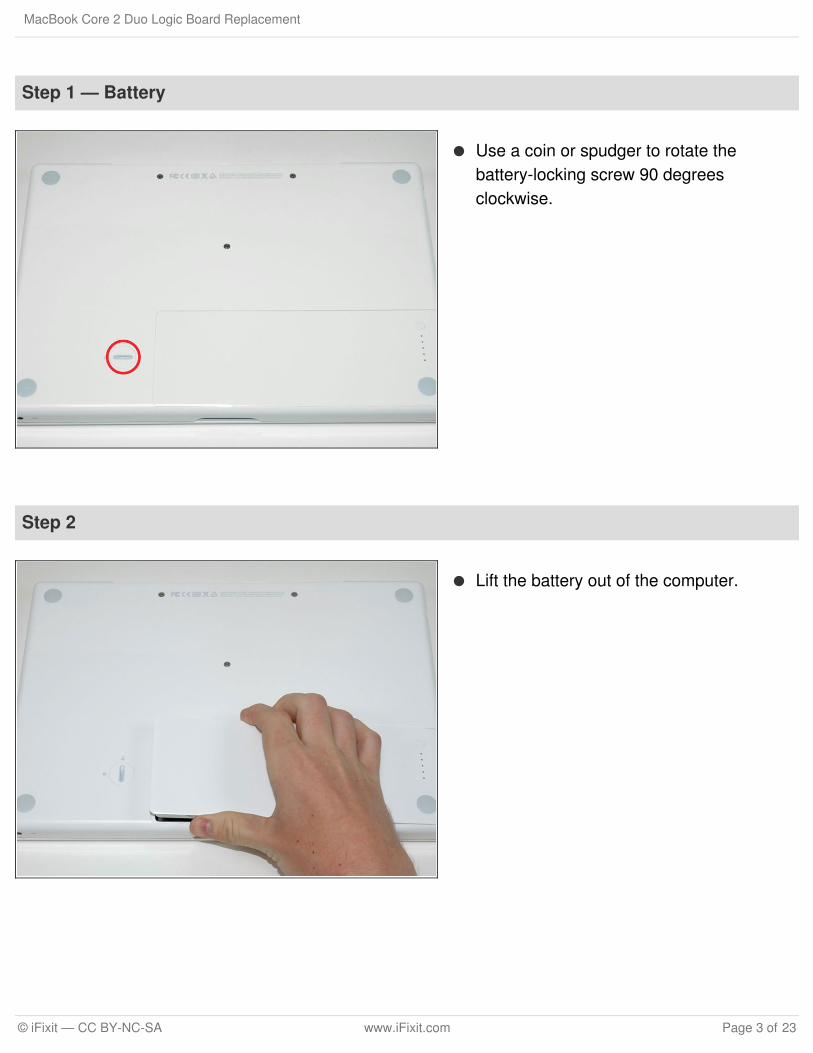
Step 1 — Battery
Use a coin or spudger to rotate thebattery-locking screw 90 degreesclockwise.
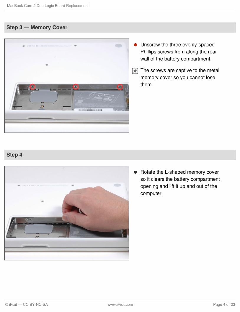
Step 2
Lift the battery out of the computer.
MacBook Core 2 Duo Logic Board Replacement
© iFixit — CC BY-NC-SA www.iFixit.com Page 3 of 23
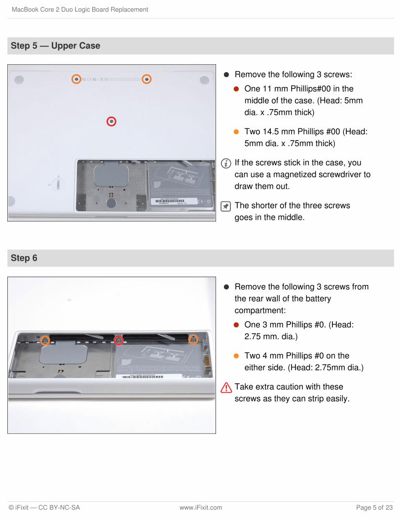
Step 3 — Memory Cover
Unscrew the three evenly-spacedPhillips screws from along the rearwall of the battery compartment.
The screws are captive to the metalmemory cover so you cannot losethem.
Step 4
Rotate the L-shaped memory coverso it clears the battery compartmentopening and lift it up and out of thecomputer.
MacBook Core 2 Duo Logic Board Replacement
© iFixit — CC BY-NC-SA www.iFixit.com Page 4 of 23
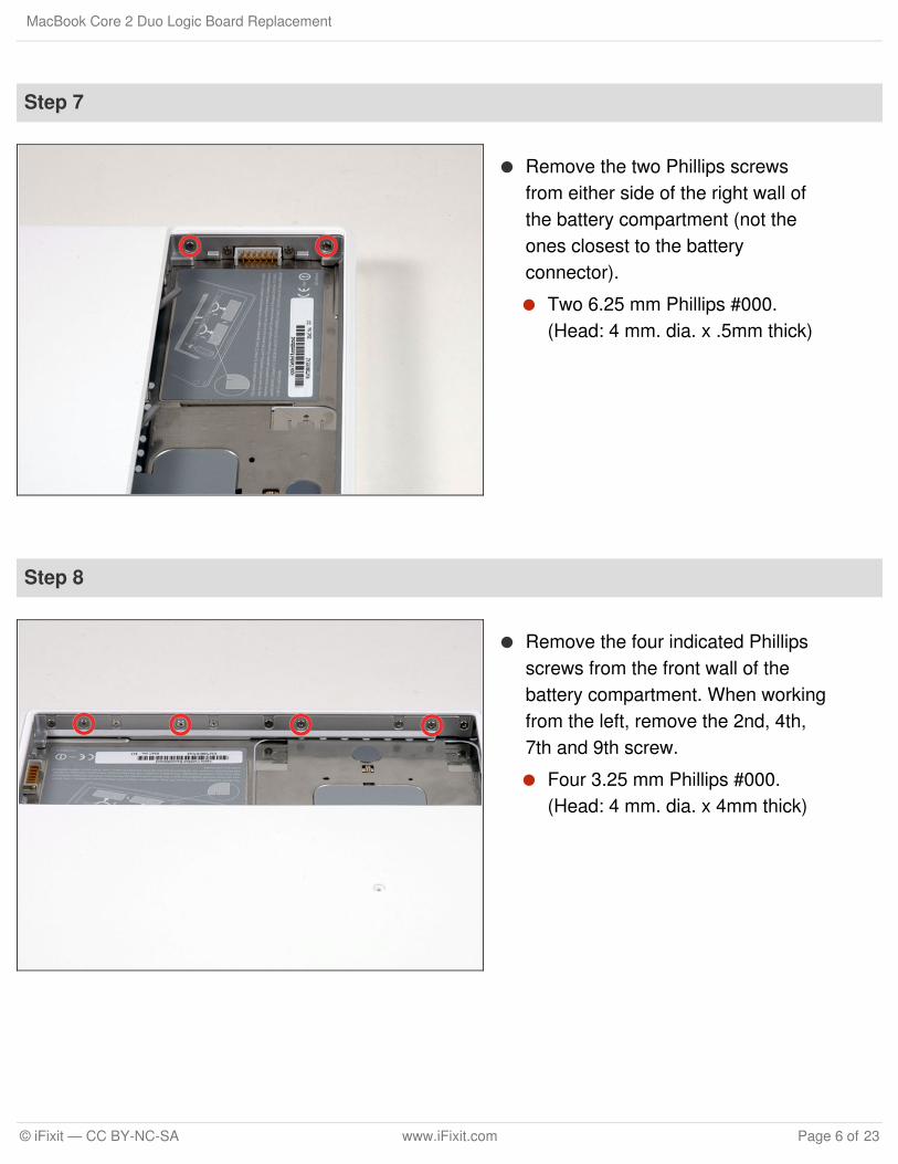
Step 5 — Upper Case
Remove the following 3 screws:
One 11 mm Phillips#00 in themiddle of the case. (Head: 5mmdia. x .75mm thick)
Two 14.5 mm Phillips #00 (Head:5mm dia. x .75mm thick)
If the screws stick in the case, youcan use a magnetized screwdriver todraw them out.
The shorter of the three screwsgoes in the middle.
Step 6
Remove the following 3 screws fromthe rear wall of the batterycompartment:
One 3 mm Phillips #0. (Head:2.75 mm. dia.)
Two 4 mm Phillips #0 on theeither side. (Head: 2.75mm dia.)
Take extra caution with thesescrews as they can strip easily.
MacBook Core 2 Duo Logic Board Replacement
© iFixit — CC BY-NC-SA www.iFixit.com Page 5 of 23
Step 7
Remove the two Phillips screwsfrom either side of the right wall ofthe battery compartment (not theones closest to the batteryconnector).
Two 6.25 mm Phillips #000.(Head: 4 mm. dia. x .5mm thick)
Step 8
Remove the four indicated Phillipsscrews from the front wall of thebattery compartment. When workingfrom the left, remove the 2nd, 4th,7th and 9th screw.
Four 3.25 mm Phillips #000.(Head: 4 mm. dia. x 4mm thick)
MacBook Core 2 Duo Logic Board Replacement
© iFixit — CC BY-NC-SA www.iFixit.com Page 6 of 23
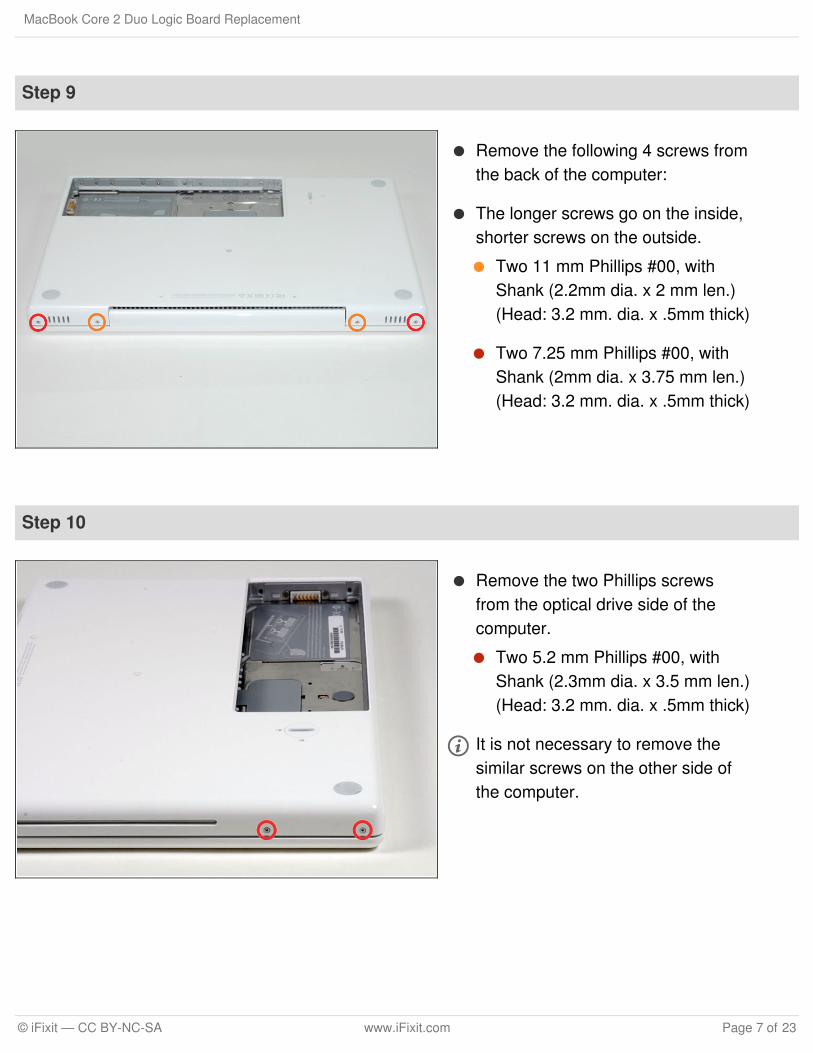
Step 9
Remove the following 4 screws fromthe back of the computer:
The longer screws go on the inside,shorter screws on the outside.
Two 11 mm Phillips #00, withShank (2.2mm dia. x 2 mm len.)(Head: 3.2 mm. dia. x .5mm thick)
Two 7.25 mm Phillips #00, withShank (2mm dia. x 3.75 mm len.)(Head: 3.2 mm. dia. x .5mm thick)
Step 10
Remove the two Phillips screwsfrom the optical drive side of thecomputer.
Two 5.2 mm Phillips #00, withShank (2.3mm dia. x 3.5 mm len.)(Head: 3.2 mm. dia. x .5mm thick)
It is not necessary to remove thesimilar screws on the other side ofthe computer.
MacBook Core 2 Duo Logic Board Replacement
© iFixit — CC BY-NC-SA www.iFixit.com Page 7 of 23
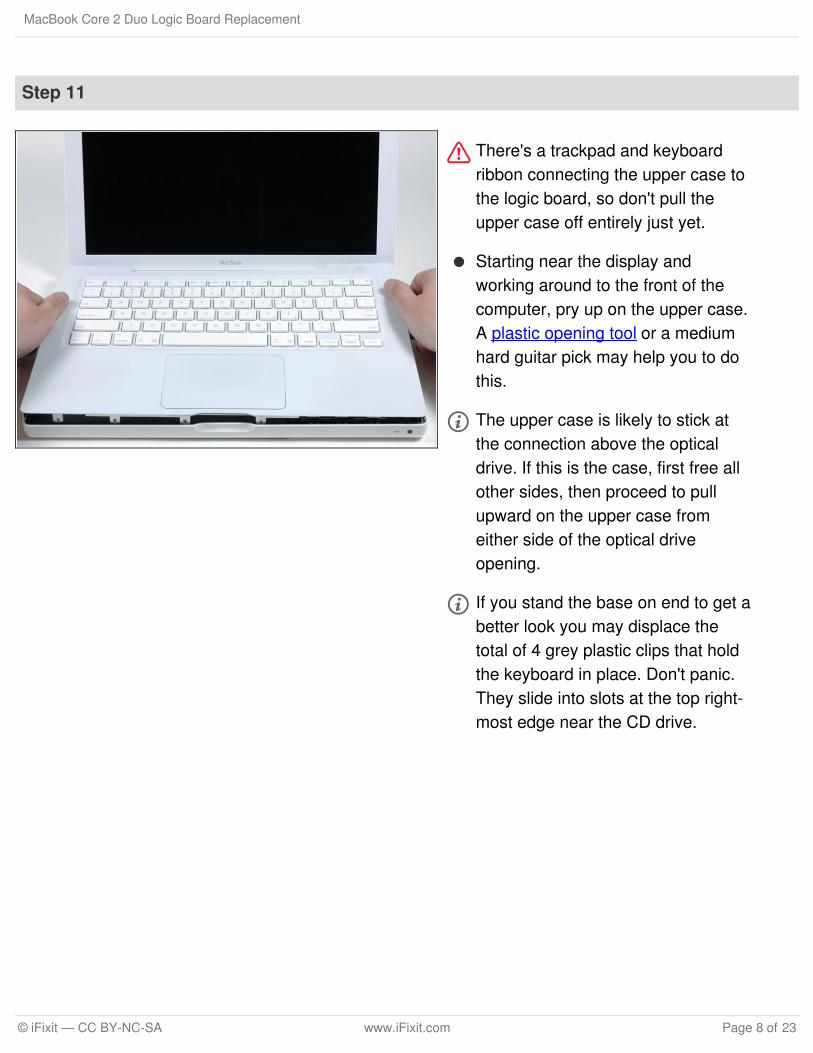
Step 11
There's a trackpad and keyboardribbon connecting the upper case tothe logic board, so don't pull theupper case off entirely just yet.
Starting near the display andworking around to the front of thecomputer, pry up on the upper case.A plastic opening tool or a mediumhard guitar pick may help you to dothis.
The upper case is likely to stick atthe connection above the opticaldrive. If this is the case, first free allother sides, then proceed to pullupward on the upper case fromeither side of the optical driveopening.
If you stand the base on end to get abetter look you may displace thetotal of 4 grey plastic clips that holdthe keyboard in place. Don't panic.They slide into slots at the top right-most edge near the CD drive.
MacBook Core 2 Duo Logic Board Replacement
© iFixit — CC BY-NC-SA www.iFixit.com Page 8 of 23
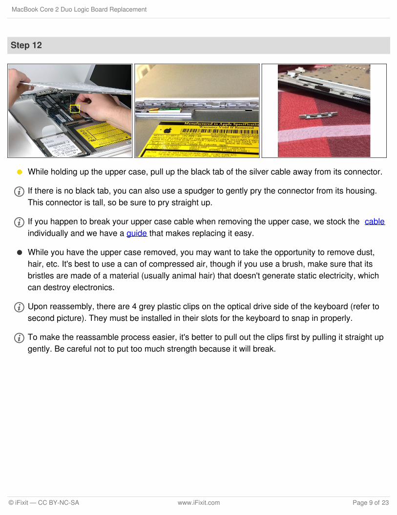
Step 12
While holding up the upper case, pull up the black tab of the silver cable away from its connector.
If there is no black tab, you can also use a spudger to gently pry the connector from its housing.This connector is tall, so be sure to pry straight up.
If you happen to break your upper case cable when removing the upper case, we stock the cableindividually and we have a guide that makes replacing it easy.
While you have the upper case removed, you may want to take the opportunity to remove dust,hair, etc. It's best to use a can of compressed air, though if you use a brush, make sure that itsbristles are made of a material (usually animal hair) that doesn't generate static electricity, whichcan destroy electronics.
Upon reassembly, there are 4 grey plastic clips on the optical drive side of the keyboard (refer tosecond picture). They must be installed in their slots for the keyboard to snap in properly.
To make the reassamble process easier, it's better to pull out the clips first by pulling it straight upgently. Be careful not to put too much strength because it will break.
MacBook Core 2 Duo Logic Board Replacement
© iFixit — CC BY-NC-SA www.iFixit.com Page 9 of 23
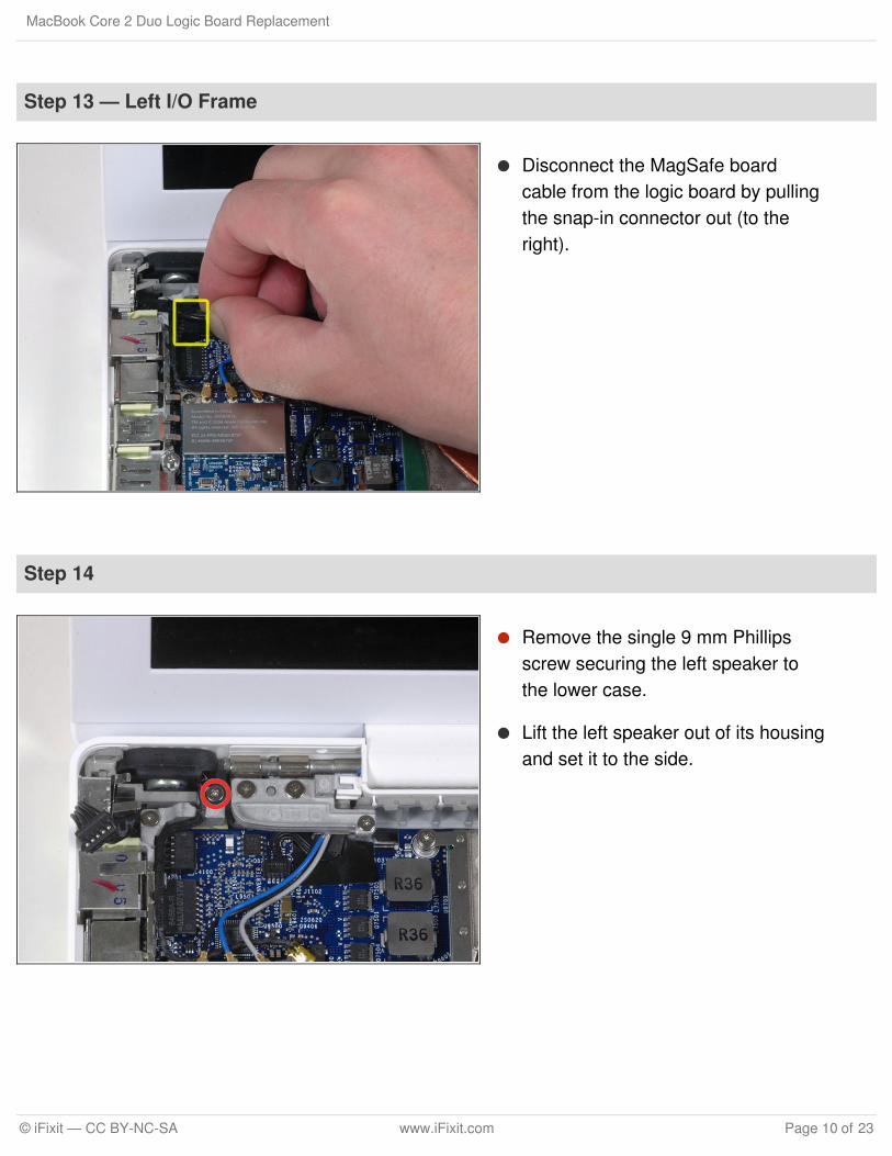
Step 13 — Left I/O Frame
Disconnect the MagSafe boardcable from the logic board by pullingthe snap-in connector out (to theright).
Step 14
Remove the single 9 mm Phillipsscrew securing the left speaker tothe lower case.
Lift the left speaker out of its housingand set it to the side.
MacBook Core 2 Duo Logic Board Replacement
© iFixit — CC BY-NC-SA www.iFixit.com Page 10 of 23
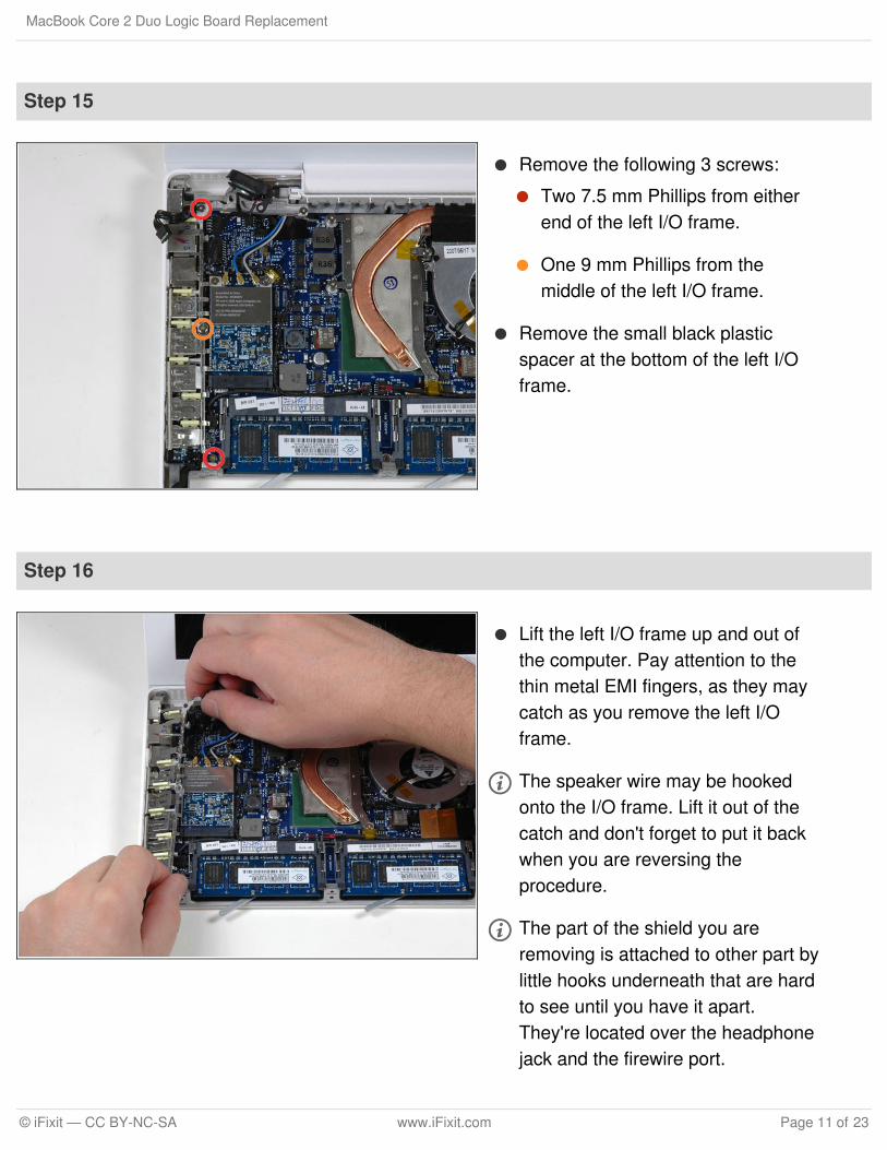
Step 15
Remove the following 3 screws:
Two 7.5 mm Phillips from eitherend of the left I/O frame.
One 9 mm Phillips from themiddle of the left I/O frame.
Remove the small black plasticspacer at the bottom of the left I/Oframe.
Step 16
Lift the left I/O frame up and out ofthe computer. Pay attention to thethin metal EMI fingers, as they maycatch as you remove the left I/Oframe.
The speaker wire may be hookedonto the I/O frame. Lift it out of thecatch and don't forget to put it backwhen you are reversing theprocedure.
The part of the shield you areremoving is attached to other part bylittle hooks underneath that are hardto see until you have it apart.They're located over the headphonejack and the firewire port.
MacBook Core 2 Duo Logic Board Replacement
© iFixit — CC BY-NC-SA www.iFixit.com Page 11 of 23
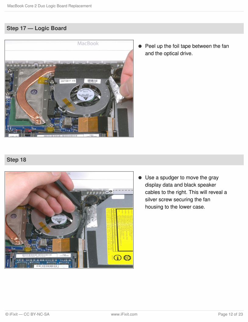
Step 17 — Logic Board
Peel up the foil tape between the fanand the optical drive.
Step 18
Use a spudger to move the graydisplay data and black speakercables to the right. This will reveal asilver screw securing the fanhousing to the lower case.
MacBook Core 2 Duo Logic Board Replacement
© iFixit — CC BY-NC-SA www.iFixit.com Page 12 of 23
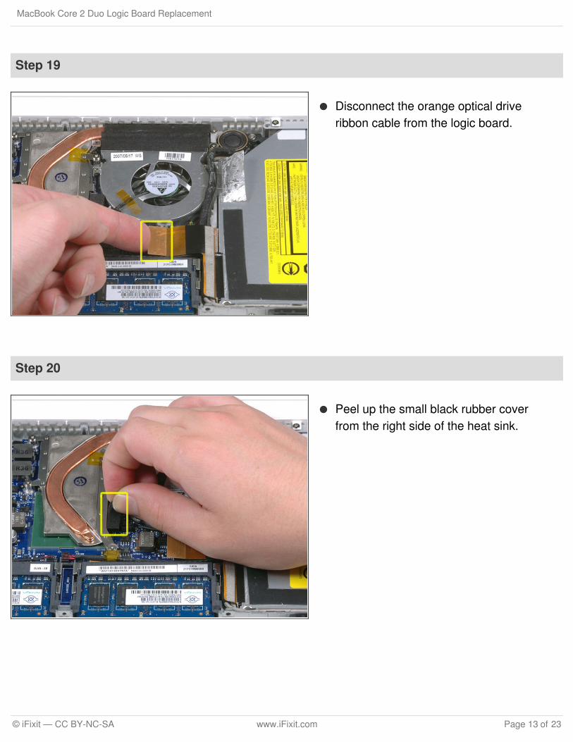
Step 19
Disconnect the orange optical driveribbon cable from the logic board.
Step 20
Peel up the small black rubber coverfrom the right side of the heat sink.
MacBook Core 2 Duo Logic Board Replacement
© iFixit — CC BY-NC-SA www.iFixit.com Page 13 of 23
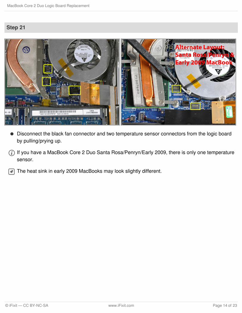
Step 21
Disconnect the black fan connector and two temperature sensor connectors from the logic boardby pulling/prying up.
If you have a MacBook Core 2 Duo Santa Rosa/Penryn/Early 2009, there is only one temperaturesensor.
The heat sink in early 2009 MacBooks may look slightly different.
MacBook Core 2 Duo Logic Board Replacement
© iFixit — CC BY-NC-SA www.iFixit.com Page 14 of 23
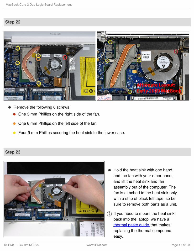
Step 22
Remove the following 6 screws:
One 3 mm Phillips on the right side of the fan.
One 6 mm Phillips on the left side of the fan.
Four 9 mm Phillips securing the heat sink to the lower case.
Step 23
Hold the heat sink with one handand the fan with your other hand,and lift the heat sink and fanassembly out of the computer. Thefan is attached to the heat sink onlywith a strip of black felt tape, so besure to remove both parts as a unit.
If you need to mount the heat sinkback into the laptop, we have athermal paste guide that makesreplacing the thermal compoundeasy.
MacBook Core 2 Duo Logic Board Replacement
© iFixit — CC BY-NC-SA www.iFixit.com Page 15 of 23
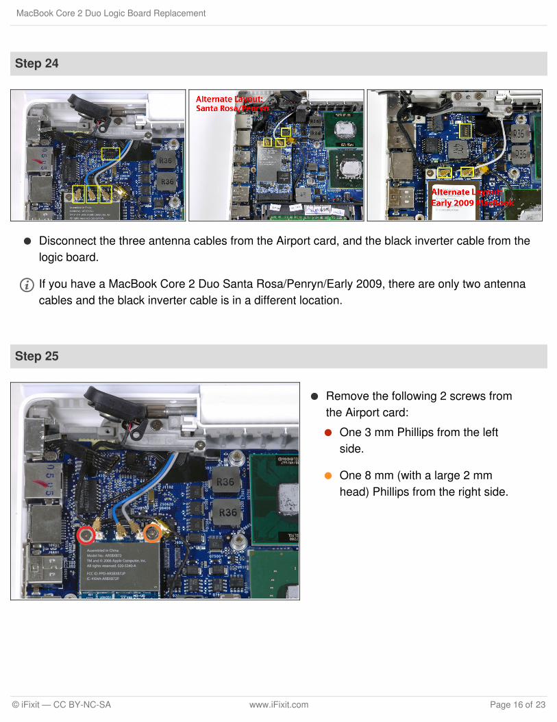
Step 24
Disconnect the three antenna cables from the Airport card, and the black inverter cable from thelogic board.
If you have a MacBook Core 2 Duo Santa Rosa/Penryn/Early 2009, there are only two antennacables and the black inverter cable is in a different location.
Step 25
Remove the following 2 screws fromthe Airport card:
One 3 mm Phillips from the leftside.
One 8 mm (with a large 2 mmhead) Phillips from the right side.
MacBook Core 2 Duo Logic Board Replacement
© iFixit — CC BY-NC-SA www.iFixit.com Page 16 of 23
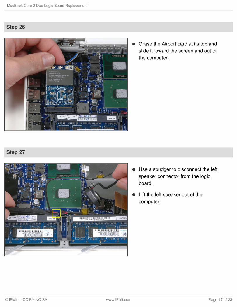
Step 26
Grasp the Airport card at its top andslide it toward the screen and out ofthe computer.
Step 27
Use a spudger to disconnect the leftspeaker connector from the logicboard.
Lift the left speaker out of thecomputer.
MacBook Core 2 Duo Logic Board Replacement
© iFixit — CC BY-NC-SA www.iFixit.com Page 17 of 23
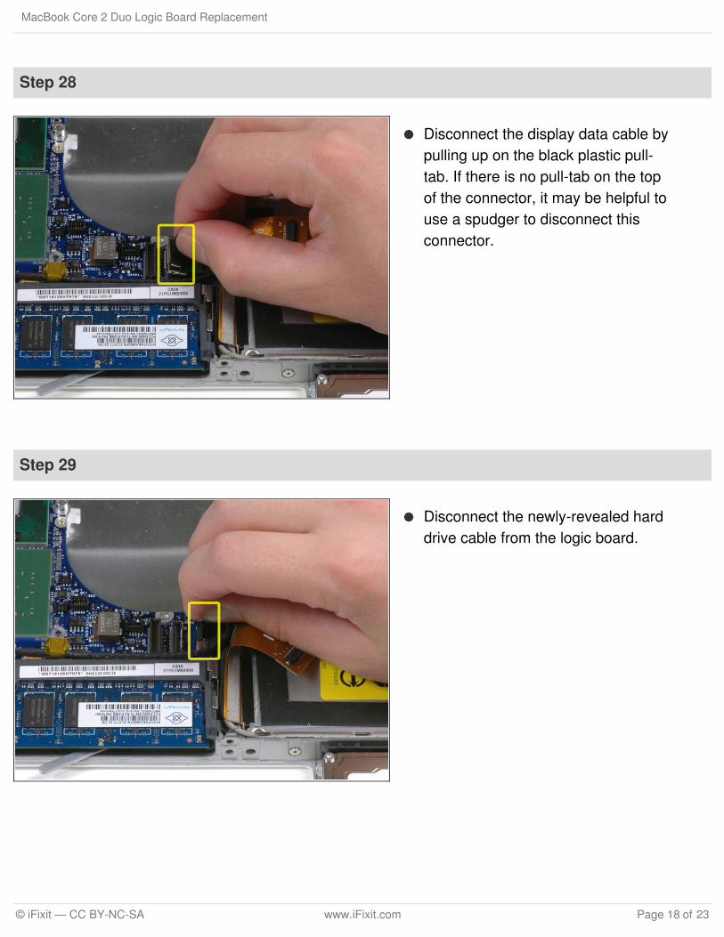
Step 28
Disconnect the display data cable bypulling up on the black plastic pull-tab. If there is no pull-tab on the topof the connector, it may be helpful touse a spudger to disconnect thisconnector.
Step 29
Disconnect the newly-revealed harddrive cable from the logic board.
MacBook Core 2 Duo Logic Board Replacement
© iFixit — CC BY-NC-SA www.iFixit.com Page 18 of 23
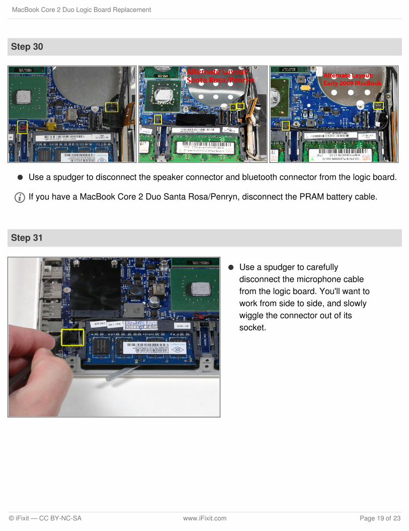
Step 30
Use a spudger to disconnect the speaker connector and bluetooth connector from the logic board.
If you have a MacBook Core 2 Duo Santa Rosa/Penryn, disconnect the PRAM battery cable.
Step 31
Use a spudger to carefullydisconnect the microphone cablefrom the logic board. You'll want towork from side to side, and slowlywiggle the connector out of itssocket.
MacBook Core 2 Duo Logic Board Replacement
© iFixit — CC BY-NC-SA www.iFixit.com Page 19 of 23
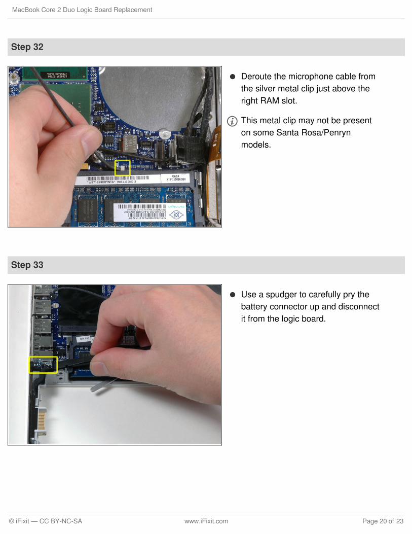
Step 32
Deroute the microphone cable fromthe silver metal clip just above theright RAM slot.
This metal clip may not be presenton some Santa Rosa/Penrynmodels.
Step 33
Use a spudger to carefully pry thebattery connector up and disconnectit from the logic board.
MacBook Core 2 Duo Logic Board Replacement
© iFixit — CC BY-NC-SA www.iFixit.com Page 20 of 23
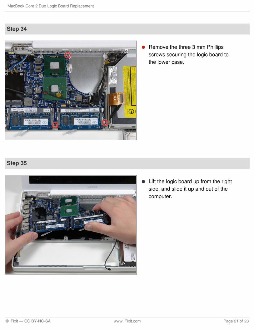
Step 34
Remove the three 3 mm Phillipsscrews securing the logic board tothe lower case.
Step 35
Lift the logic board up from the rightside, and slide it up and out of thecomputer.
MacBook Core 2 Duo Logic Board Replacement
© iFixit — CC BY-NC-SA www.iFixit.com Page 21 of 23
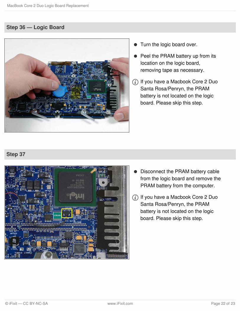
Step 36 — Logic Board
Turn the logic board over.
Peel the PRAM battery up from itslocation on the logic board,removing tape as necessary.
If you have a Macbook Core 2 DuoSanta Rosa/Penryn, the PRAMbattery is not located on the logicboard. Please skip this step.
Step 37
Disconnect the PRAM battery cablefrom the logic board and remove thePRAM battery from the computer.
If you have a Macbook Core 2 DuoSanta Rosa/Penryn, the PRAMbattery is not located on the logicboard. Please skip this step.
MacBook Core 2 Duo Logic Board Replacement
© iFixit — CC BY-NC-SA www.iFixit.com Page 22 of 23
To reassemble your device, follow these instructions in reverse order.
This document was last generated on 2018-02-13 10:50:14 PM.
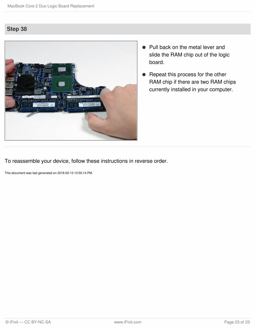
Step 38
Pull back on the metal lever andslide the RAM chip out of the logicboard.
Repeat this process for the otherRAM chip if there are two RAM chipscurrently installed in your computer.
MacBook Core 2 Duo Logic Board Replacement
© iFixit — CC BY-NC-SA www.iFixit.com Page 23 of 23


![$PD]RQ.LQGOH)LUH+' 'LVDVVHPEOH*XLGH · Amazon Kindle Fire HD 7.0–Disassemble Guide Unplug the connection for the battery from the motherboard with the spudger. • Use the small](https://img.pdfslide.us/doc/110x75/5e80998e69390668f01b3a89/pdrqlqgohluh-lvdvvhpeohxlgh-amazon-kindle-fire-hd-70adisassemble-guide.jpg)