Embed Size (px)
Citation preview
ODU-Steckverbindungssysteme GmbH & Co. KG, Pregelstraße 11, D-84453 Mühldorf/InnTelephone: +49/86 31/61 56-0, Telefax: +49/86 31/61 56 49, E-Mail: [email protected], www.odu.de
Catalogue No. 1004-c
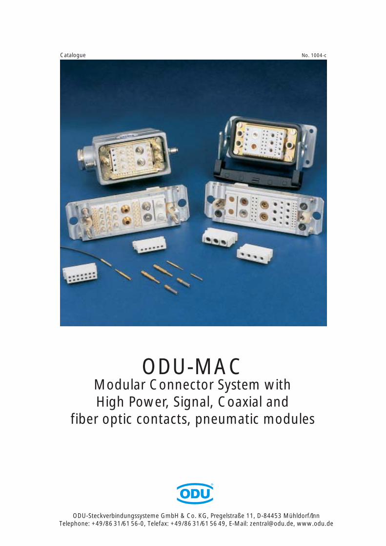
ODU-MACModular Connector System withHigh Power, Signal, Coaxial and
fiber optic contacts, pneumatic modules
Product description:
The ODU-MAC connector system consists of a variety of customizable rugged frames, plastic insulationbodies (modules) with many of insert patterns, and crimpable, removable contacts for high currents (power),low currents (signal), and RF-signals. Modules can be arranged in different patterns in the frame accordingto application. Unit spacing is 2.54 mm (.100") or a multiple thereof. Guide pins and guide bushings prevent misconnections and provide easy alignment for accurate mating.
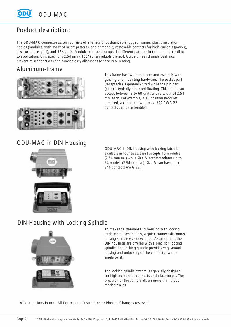
This frame has two end pieces and two rails withguiding and mounting hardware. The socket part(receptacle) is generally fixed while the pin part(plug) is typically mounted floating. This frame canaccept between 3 to 60 units with a width of 2.54mm each. For example, if 10 position modules are used, a connector with max. 600 AWG 22contacts can be assembled.
ODU-MAC in DIN housing with locking latch is available in four sizes. Size I accepts 10 modules(2.54 mm ea.) while Size IV accommodates up to 34 models (2.54 mm ea.). Size IV can have max.340 contacts AWG 22.
To make the standard DIN housing with lockinglatch more user-friendly, a quick connect-disconnectlocking spindle was developed. As an option, theDIN housings are offered with a precision lockingspindle. The locking spindle provides very smoothlocking and unlocking of the connector with asingle twist.
The locking spindle system is especially designed for high number of connects and disconnects. Theprecision of the spindle allows more than 5,000mating cycles.
Aluminum-Frame
ODU-MAC in DIN Housing
DIN-Housing with Locking Spindle
All dimensions in mm. All figures are illustrations or Photos. Changes reserved.
ODU-MAC
Page 2 ODU -Steckverbindungssysteme GmbH & Co. KG, Pregelstr. 11, D-84453 Mühldorf/Inn, Tel. +49/86 31/61 56-0, Fax +49/86 31/61 56 49, www.odu.de
ODU-MAC
ODU -Steckverbindungssysteme GmbH & Co. KG, Pregelstr. 11, D-84453 Mühldorf/Inn, Tel. +49/86 31/61 56-0, Fax +49/86 31/61 56 49, www.odu.de Page 3
Contents Page
ODU-MAC Product Description 2
ODU-Springwire Contact Principle 4
ODU-MAC Modules: Insulation Bodies, Contacts, Technical Data 7
ODU-MAC Aluminum Frame 25
ODU-MAC DIN Frame 29
ODU-MAC DIN Housing 31
ODU-MAC Crimp Tools 36
Technical Information 42
ODU-MAC Application Examples 48
Technical Article 51
ODU-MAC
Page 4 ODU -Steckverbindungssysteme GmbH & Co. KG, Pregelstr. 11, D-84453 Mühldorf/Inn, Tel. +49/86 31/61 56-0, Fax +49/86 31/61 56 49, www.odu.de
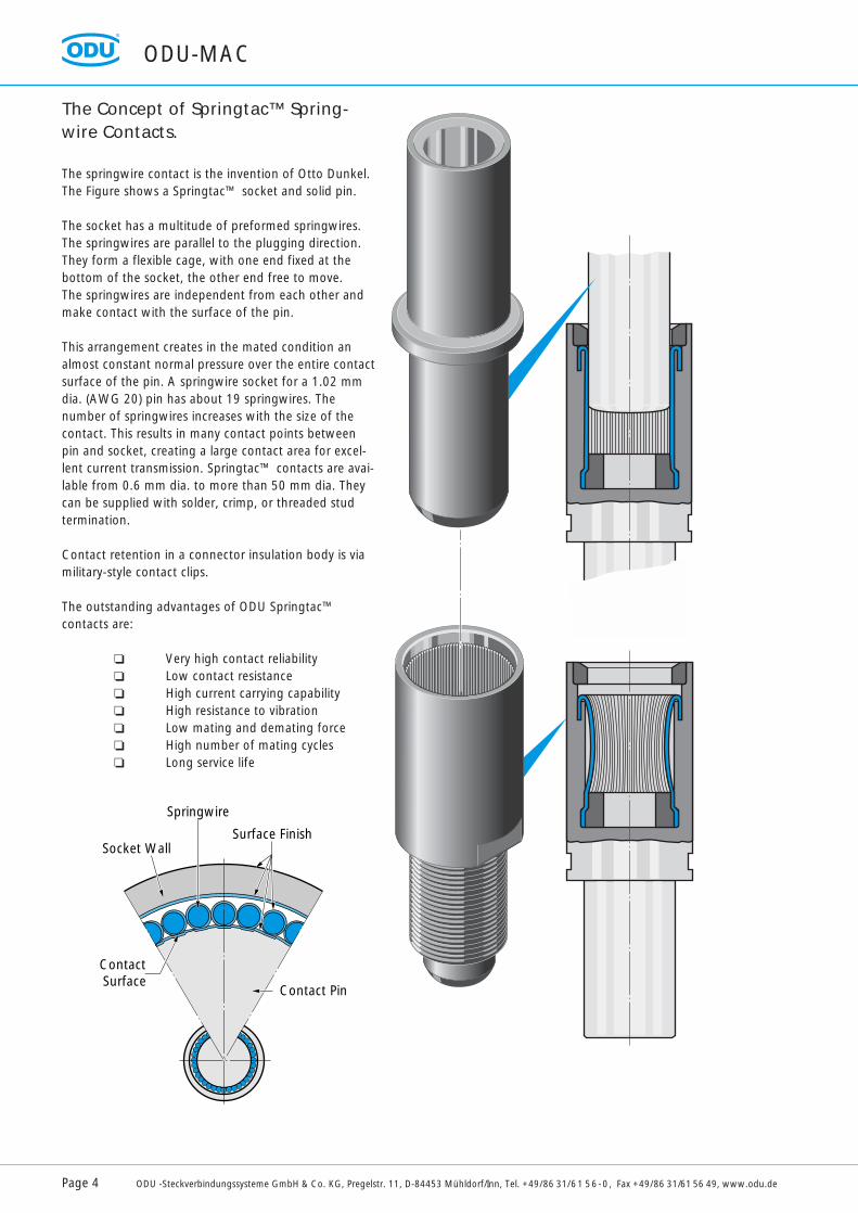
The Concept of Springtac™ Spring-wire Contacts.
The springwire contact is the invention of Otto Dunkel.The Figure shows a Springtac™ socket and solid pin.
The socket has a multitude of preformed springwires.The springwires are parallel to the plugging direction.They form a flexible cage, with one end fixed at thebottom of the socket, the other end free to move.The springwires are independent from each other andmake contact with the surface of the pin.
This arrangement creates in the mated condition analmost constant normal pressure over the entire contactsurface of the pin. A springwire socket for a 1.02 mmdia. (AWG 20) pin has about 19 springwires. The number of springwires increases with the size of thecontact. This results in many contact points betweenpin and socket, creating a large contact area for excel-lent current transmission. Springtac™ contacts are avai-lable from 0.6 mm dia. to more than 50 mm dia. Theycan be supplied with solder, crimp, or threaded studtermination.
Contact retention in a connector insulation body is viamilitary-style contact clips.
The outstanding advantages of ODU Springtac™contacts are:
Very high contact reliability Low contact resistance High current carrying capability High resistance to vibration Low mating and demating force High number of mating cycles Long service life
Socket Wall
Springwire
Surface Finish
Contact Surface
Contact Pin
ODU-MAC
ODU -Steckverbindungssysteme GmbH & Co. KG, Pregelstr. 11, D-84453 Mühldorf/Inn, Tel. +49/86 31/61 56-0, Fax +49/86 31/61 56 49, www.odu.de Page 5
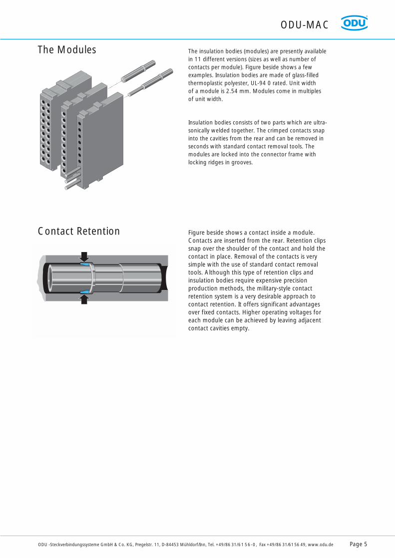
The Modules The insulation bodies (modules) are presently availablein 11 different versions (sizes as well as number ofcontacts per module). Figure beside shows a fewexamples. Insulation bodies are made of glass-filledthermoplastic polyester, UL-94 0 rated. Unit width of a module is 2.54 mm. Modules come in multiples of unit width.
Insulation bodies consists of two parts which are ultra-sonically welded together. The crimped contacts snapinto the cavities from the rear and can be removed inseconds with standard contact removal tools. Themodules are locked into the connector frame withlocking ridges in grooves.
Contact Retention Figure beside shows a contact inside a module.Contacts are inserted from the rear. Retention clipssnap over the shoulder of the contact and hold thecontact in place. Removal of the contacts is verysimple with the use of standard contact removaltools. Although this type of retention clips and insulation bodies require expensive precision production methods, the military-style contactretention system is a very desirable approach tocontact retention. It offers significant advantagesover fixed contacts. Higher operating voltages foreach module can be achieved by leaving adjacent contact cavities empty.

For your notes
Page 6 ODU -Steckverbindungssysteme GmbH & Co. KG, Pregelstr. 11, D-84453 Mühldorf/Inn, Tel. +49/86 31/61 56-0, Fax +49/86 31/61 56 49, www.odu.de
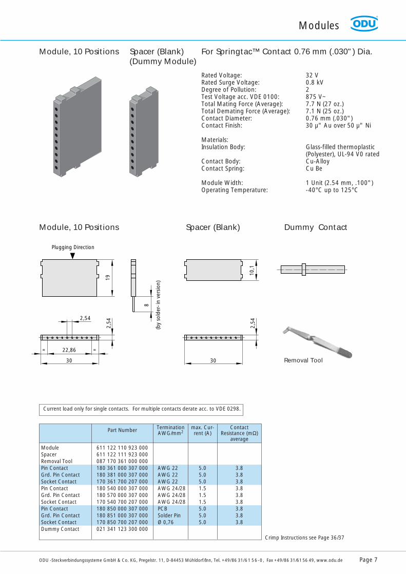
Rated Voltage: 32 VRated Surge Voltage: 0.8 kVDegree of Pollution: 2Test Voltage acc. VDE 0100: 875 V~Total Mating Force (Average): 7.7 N (27 oz.)Total Demating Force (Average): 7.1 N (25 oz.)Contact Diameter: 0.76 mm (.030")Contact Finish: 30 µ" Au over 50 µ" Ni
Materials:Insulation Body: Glass-filled thermoplastic
(Polyester), UL-94 V0 ratedContact Body: Cu-AlloyContact Spring: Cu Be
Module Width: 1 Unit (2.54 mm, .100")Operating Temperature: -40°C up to 125°C
Module, 10 Positions Spacer (Blank) (Dummy Module)
ModuleSpacerRemoval ToolPin ContactGrd. Pin ContactSocket ContactPin ContactGrd. Pin ContactSocket ContactPin ContactGrd. Pin ContactSocket ContactDummy Contact
611 122 110 923 000611 122 111 923 000087 170 361 000 000180 361 000 307 000180 381 000 307 000170 361 700 207 000180 540 000 307 000180 570 000 307 000170 540 700 207 000180 850 000 307 000180 851 000 307 000170 850 700 207 000021 341 123 300 000
AWG 22AWG 22AWG 22AWG 24/28AWG 24/28AWG 24/28PCB Solder PinØ 0,76
max. Cur-rent (A)
TerminationAWG/mm2Part Number
5.0 5.05.01.51.51.55.05.05.0
ContactResistance (mΩ)
average
3.83.83.83.83.83.83.83.83.8
Crimp Instructions see Page 36/37
Current load only for single contacts. For multiple contacts derate acc. to VDE 0298.
19
2,54
22,86= =
30
Plugging Direction
2,54
10,1
30
2,54
X
Dim. X for 8-point Crimp
8
(by
sold
er- i
n ve
rsio
n)
Module, 10 Positions Spacer (Blank) Dummy Contact
For Springtac™ Contact 0.76 mm (.030") Dia.
Modules
ODU -Steckverbindungssysteme GmbH & Co. KG, Pregelstr. 11, D-84453 Mühldorf/Inn, Tel. +49/86 31/61 56-0, Fax +49/86 31/61 56 49, www.odu.de Page 7
Removal Tool
Modules
Page 8 ODU -Steckverbindungssysteme GmbH & Co. KG, Pregelstr. 11, D-84453 Mühldorf/Inn, Tel. +49/86 31/61 56-0, Fax +49/86 31/61 56 49, www.odu.de
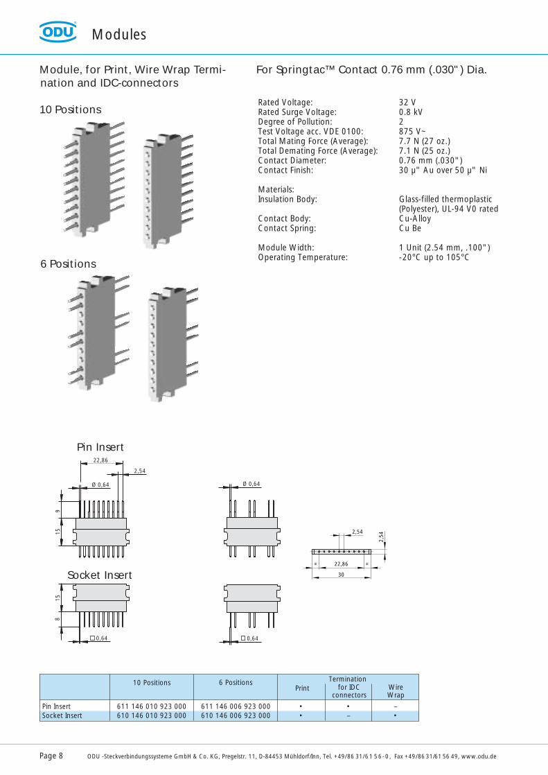
Rated Voltage: 32 VRated Surge Voltage: 0.8 kVDegree of Pollution: 2Test Voltage acc. VDE 0100: 875 V~Total Mating Force (Average): 7.7 N (27 oz.)Total Demating Force (Average): 7.1 N (25 oz.)Contact Diameter: 0.76 mm (.030")Contact Finish: 30 µ" Au over 50 µ" Ni
Materials:Insulation Body: Glass-filled thermoplastic
(Polyester), UL-94 V0 ratedContact Body: Cu-AlloyContact Spring: Cu Be
Module Width: 1 Unit (2.54 mm, .100")Operating Temperature: -20°C up to 105°C
Pin InsertSocket Insert
611 146 010 923 000610 146 010 923 000
611 146 006 923 000610 146 006 923 000
Print6 Positions10 Positions
••
for IDC connectors
WireWrap
•–
–•
For Springtac™ Contact 0.76 mm (.030") Dia. Module, for Print, Wire Wrap Termi-nation and IDC-connectors
6 Positions
10 Positions
22,86
2,54
Ø 0,64 Ø 0,64
915
815
0,64 0,64
2,54
22,86= =
30
2,54
Termination
Pin Insert
Socket Insert
Modules
ODU -Steckverbindungssysteme GmbH & Co. KG, Pregelstr. 11, D-84453 Mühldorf/Inn, Tel. +49/86 31/61 56-0, Fax +49/86 31/61 56 49, www.odu.de Page 9
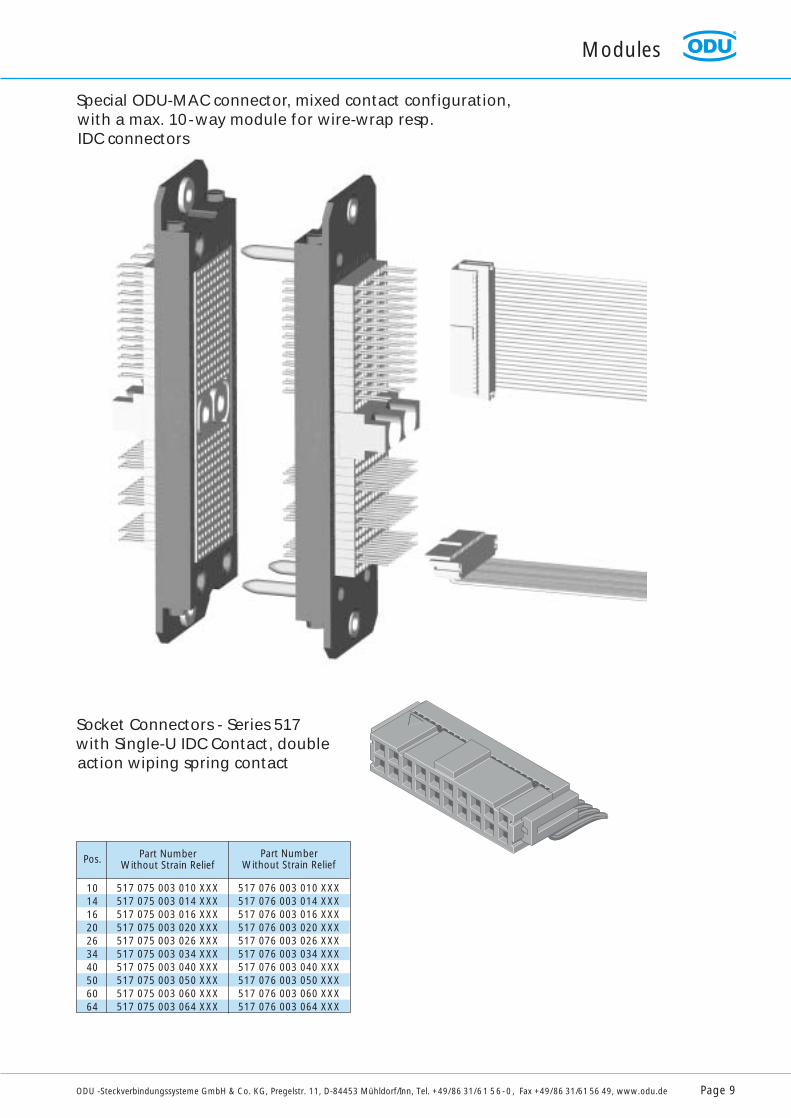
Special ODU-MAC connector, mixed contact configuration,with a max. 10-way module for wire-wrap resp.IDC connectors
Socket Connectors - Series 517with Single-U IDC Contact, doubleaction wiping spring contact
Pos.
10141620263440506064
517 075 003 010 XXX517 075 003 014 XXX517 075 003 016 XXX517 075 003 020 XXX517 075 003 026 XXX517 075 003 034 XXX517 075 003 040 XXX517 075 003 050 XXX517 075 003 060 XXX517 075 003 064 XXX
517 076 003 010 XXX517 076 003 014 XXX517 076 003 016 XXX517 076 003 020 XXX517 076 003 026 XXX517 076 003 034 XXX517 076 003 040 XXX517 076 003 050 XXX517 076 003 060 XXX517 076 003 064 XXX
Part NumberWithout Strain Relief
Part NumberWithout Strain Relief
Modules
Page 10 ODU -Steckverbindungssysteme GmbH & Co. KG, Pregelstr. 11, D-84453 Mühldorf/Inn, Tel. +49/86 31/61 56-0, Fax +49/86 31/61 56 49, www.odu.de
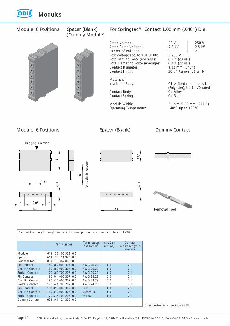
Rated Voltage: 63 V 250 VRated Surge Voltage: 2.5 kV 2.5 kVDegree of Pollution: 3 2Test Voltage acc. to VDE 0100: 1,250 V~Total Mating Force (Average): 6.5 N (23 oz.) Total Demating Force (Average): 6.0 N (22 oz.) Contact Diameter: 1.02 mm (.040")Contact Finish: 30 µ" Au over 50 µ" Ni
Materials:Insulation Body: Glass-filled thermoplastic
(Polyester), UL-94 V0 ratedContact Body: Cu-AlloyContact Springs: Cu Be
Module Width: 2 Units (5.08 mm, .200 ")Operating Temperature: -40°C up to 125°C
ModuleSpacerRemoval ToolPin ContactGrd. Pin ContactSocket ContactPin ContactGrd. Pin ContactSocket ContactPin ContactGrd. Pin ContactSocket ContactDummy Contact
611 123 106 923 000611 123 111 923 000087 170 362 000 000180 362 000 307 000180 382 000 307 000170 362 700 207 000180 544 000 307 000180 574 000 307 000170 544 700 207 000180 818 000 307 000180 819 000 307 000170 818 700 207 000021 341 124 300 000
AWG 20/22AWG 20/22AWG 20/22AWG 24/28AWG 24/28AWG 24/28PCBSolder PinØ 1.02
max. Cur-rent (A)
TerminationAWG/mm2Part Number
6.0 6.06.02.02.02.06.06.06.0
ContactResistance (mΩ)
average
2.12.12.12.12.12.12.12.12.1
19
3,81
19,05= =
30
5,08
10,1
X
8
30
5,08
Plugging Direction
Dim. X for 8-point Crimp
(by
sold
er in
ver
sion
)
Current load only for single contacts. For multiple contacts derate acc. to VDE 0298.
Module, 6 Positions Spacer (Blank) (Dummy Module)
Module, 6 Positions Spacer (Blank) Dummy Contact
For Springtac™ Contact 1.02 mm (.040") Dia.
Removal Tool
Crimp Instructions see Page 36/37
Modules
ODU -Steckverbindungssysteme GmbH & Co. KG, Pregelstr. 11, D-84453 Mühldorf/Inn, Tel. +49/86 31/61 56-0, Fax +49/86 31/61 56 49, www.odu.de Page 11
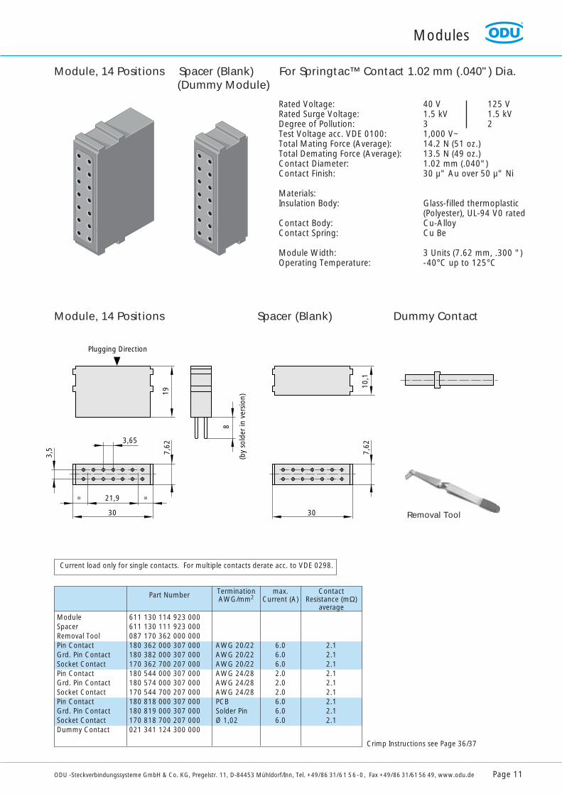
Rated Voltage: 40 V 125 VRated Surge Voltage: 1.5 kV 1.5 kVDegree of Pollution: 3 2Test Voltage acc. VDE 0100: 1,000 V~Total Mating Force (Average): 14.2 N (51 oz.)Total Demating Force (Average): 13.5 N (49 oz.)Contact Diameter: 1.02 mm (.040")Contact Finish: 30 µ" Au over 50 µ" Ni
Materials:Insulation Body: Glass-filled thermoplastic
(Polyester), UL-94 V0 ratedContact Body: Cu-AlloyContact Spring: Cu Be
Module Width: 3 Units (7.62 mm, .300 ")Operating Temperature: -40°C up to 125°C
Module, 14 Positions Spacer (Blank)(Dummy Module)
ModuleSpacerRemoval ToolPin ContactGrd. Pin ContactSocket ContactPin ContactGrd. Pin ContactSocket ContactPin ContactGrd. Pin ContactSocket ContactDummy Contact
611 130 114 923 000611 130 111 923 000087 170 362 000 000180 362 000 307 000180 382 000 307 000170 362 700 207 000180 544 000 307 000180 574 000 307 000170 544 700 207 000180 818 000 307 000180 819 000 307 000170 818 700 207 000021 341 124 300 000
AWG 20/22AWG 20/22AWG 20/22AWG 24/28AWG 24/28AWG 24/28PCBSolder PinØ 1,02
max.Current (A)
TerminationAWG/mm2Part Number
6.0 6.06.02.02.02.06.06.06.0
ContactResistance (mΩ)
average
2.12.12.12.12.12.12.12.12.1
19
3,65
21,9= =
30
7,62
10,1
X
8
3,5
30
7,62
Plugging Direction
Dim. X for 8-Point Crimp
(by
sold
er in
ver
sion
)
Current load only for single contacts. For multiple contacts derate acc. to VDE 0298.
Module, 14 Positions Spacer (Blank) Dummy Contact
For Springtac™ Contact 1.02 mm (.040") Dia.
Removal Tool
Crimp Instructions see Page 36/37
Modules
Page 12 ODU -Steckverbindungssysteme GmbH & Co. KG, Pregelstr. 11, D-84453 Mühldorf/Inn, Tel. +49/86 31/61 56-0, Fax +49/86 31/61 56 49, www.odu.de
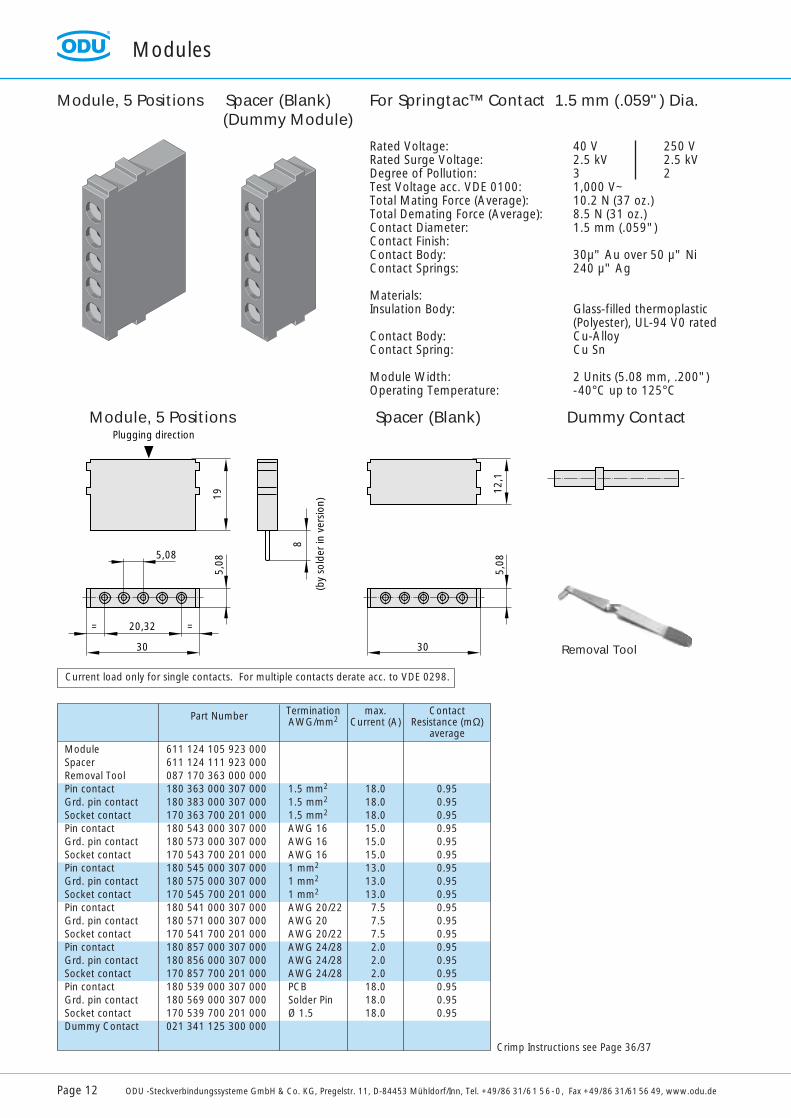
Rated Voltage: 40 V 250 VRated Surge Voltage: 2.5 kV 2.5 kVDegree of Pollution: 3 2Test Voltage acc. VDE 0100: 1,000 V~Total Mating Force (Average): 10.2 N (37 oz.)Total Demating Force (Average): 8.5 N (31 oz.)Contact Diameter: 1.5 mm (.059")Contact Finish:Contact Body: 30µ" Au over 50 µ" NiContact Springs: 240 µ" Ag
Materials:Insulation Body: Glass-filled thermoplastic
(Polyester), UL-94 V0 ratedContact Body: Cu-AlloyContact Spring: Cu Sn
Module Width: 2 Units (5.08 mm, .200")Operating Temperature: -40°C up to 125°C
Module, 5 Positions Spacer (Blank)(Dummy Module)
19
5,08
20,32= =
30
5,08
12,1
X
8
30
5,08
Plugging direction
Dim. X for 8-Point Crimp
(by
sold
er in
ver
sion
)
Current load only for single contacts. For multiple contacts derate acc. to VDE 0298.
Module, 5 Positions Spacer (Blank) Dummy Contact
For Springtac™ Contact 1.5 mm (.059") Dia.
ModuleSpacerRemoval ToolPin contactGrd. pin contactSocket contactPin contactGrd. pin contactSocket contactPin contactGrd. pin contactSocket contactPin contactGrd. pin contactSocket contactPin contactGrd. pin contactSocket contactPin contactGrd. pin contactSocket contactDummy Contact
611 124 105 923 000611 124 111 923 000087 170 363 000 000180 363 000 307 000180 383 000 307 000170 363 700 201 000180 543 000 307 000180 573 000 307 000170 543 700 201 000180 545 000 307 000180 575 000 307 000170 545 700 201 000180 541 000 307 000180 571 000 307 000170 541 700 201 000180 857 000 307 000180 856 000 307 000170 857 700 201 000180 539 000 307 000180 569 000 307 000170 539 700 201 000021 341 125 300 000
1.5 mm2
1.5 mm2
1.5 mm2
AWG 16AWG 16AWG 161 mm2
1 mm2
1 mm2
AWG 20/22AWG 20AWG 20/22AWG 24/28AWG 24/28AWG 24/28PCBSolder PinØ 1.5
max.Current (A)
TerminationAWG/mm2Part Number
18.0 18.018.015.0 15.015.013.0 13.013.07.57.57.52.02.02.0
18.0 18.018.0
ContactResistance (mΩ)
average
0.950.950.950.950.950.950.950.950.950.950.950.950.950.950.950.950.950.95
Removal Tool
Crimp Instructions see Page 36/37
Modules
ODU -Steckverbindungssysteme GmbH & Co. KG, Pregelstr. 11, D-84453 Mühldorf/Inn, Tel. +49/86 31/61 56-0, Fax +49/86 31/61 56 49, www.odu.de Page 13
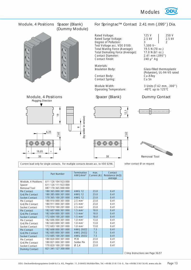
Rated Voltage: 125 V 250 VRated Surge Voltage: 2.5 kV 2.5 kVDegree of Pollution: 3 2Test Voltage acc. VDE 0100: 1,500 V~Total Mating Force (Average): 19.5 N (70 oz.)Total Demating Force (Average): 17.0 N (61 oz.)Contact Diameter: 2.41 mm (.095")Contact Finish: 240 µ" Ag
Materials:Insulation Body: Glass-filled thermoplastic
(Polyester), UL-94-V0 ratedContact Body: Cu-AlloyContact Spring: Cu Sn
Module Width: 3 Units (7.62 mm, .300")Operating Temperature: -40°C up to 125°C
Module, 4 Positions Spacer (Blank)(Dummy Module)
Module, 4 PositionsSpacerRemoval ToolPin ContactGrd.Pin ContactSocket ContactPin ContactGrd.Pin ContactSocket ContactPin ContactGrd.Pin ContactSocket ContactPin ContactGrd.Pin ContactSocket ContactPin ContactGrd.Pin ContactSocket ContactPin ContactGrd.Pin ContactSocket ContactDummy Contact
611 126 104 923 000611 126 111 923 000087 170 365 000 000180 365 000 301 000180 385 000 301 000170 365 100 201 000180 910 000 301 000180 911 000 301 000170 910 100 201 000182 607 000 301 000182 604 000 301 000172 604 100 201 000182 606 000 301 000182 603 000 301 000172 603 100 201 000182 608 000 301 000182 605 000 301 000172 605 100 201 000180 820 000 301 000180 821 000 301 000170 820 100 201 000021 341 127 300 000
AWG 12AWG 12AWG 122.5 mm2
2.5 mm2
2.5 mm2
1.5 mm2
1.5 mm2
1.5 mm2
1.0 mm2
1.0 mm2
1.0 mm2
AWG 20/22AWG 20/22AWG 20/22PCBSolder PinØ 2,4
max.Current (A)
TerminationAWG/mm2Part Number
23.023.023.023.023,023.018.018.018.013.013.013.07.57.57.523.023.023.0
ContactResistance (mΩ)
average
0.410.410.410.410.410.410.410.410.410.410.410.410.410.410.410.410.410.41
19
6,35
19,05= =
30
7,62
12,1
8
30
7,62
Plugging Direction
(by
sold
er in
ver
sion
)
Current load only for single contacts. For multiple contacts derate acc. to VDE 0298. other contact Ø on request
Module, 4 Positions Spacer (Blank) Dummy Contact
For Springtac™ Contact 2.41 mm (.095") Dia.
Removal Tool
Crimp Instructions see Page 36/37
Modules
Page 14 ODU -Steckverbindungssysteme GmbH & Co. KG, Pregelstr. 11, D-84453 Mühldorf/Inn, Tel. +49/86 31/61 56-0, Fax +49/86 31/61 56 49, www.odu.de
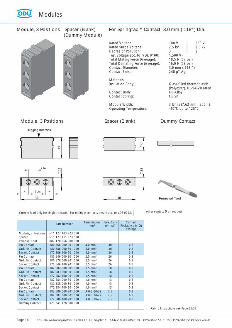
other contact Ø on request
Rated Voltage: 100 V 250 VRated Surge Voltage: 2.5 kV 2.5 kVDegree of Pollution: 3 2Test Voltage acc. to VDE 0100: 1,500 V~Total Mating Force (Average): 18.5 N (67 oz.)Total Demating Force (Average): 16.0 N (58 oz.)Contact Diameter: 3.0 mm (.118 ")Contact Finish: 240 µ" Ag
Materials:Insulation Body: Glass-filled thermoplastic
(Polyester), UL-94-V0 ratedContact Body: Cu-AlloyContact Spring: Cu Sn
Module Width: 3 Units (7.62 mm, .300 ")Operating Temperature: -40°C up to 125°C
Module, 3 Positions Spacer (Blank)(Dummy Module)
Module, 3 PositionsSpacerRemoval ToolPin ContactGrd. Pin ContactSocket ContactPin ContactGrd. Pin ContactSocket ContactPin ContactGrd. Pin ContactSocket ContactPin ContactGrd. Pin ContactSocket ContactPin ContactGrd. Pin ContactSocket ContactDummy Contact
611 127 103 923 000611 127 111 923 000087 170 366 000 000180 366 000 301 000180 386 000 301 000172 366 100 201 000180 546 000 301 000180 576 000 301 000170 546 100 201 000182 582 000 301 000182 583 000 301 000172 582 100 201 000182 584 000 301 000182 585 000 301 000172 584 100 201 000182 586 000 301 000182 587 000 301 000172 586 100 201 000021 341 128 300 000
4.0 mm2
4.0 mm2
4.0 mm2
2.5 mm2
2.5 mm2
2.5 mm2
1.5 mm2
1.5 mm2
1.5 mm2
1.0 mm2
1.0 mm2
1.0 mm2
AWG 20/22AWG 20/22AWG 20/22
max. Cur-rent (A)
Terminationmm2Part Number
3030302626261818181313137.57.57.5
ContactResistance (mΩ)
average
0.30.30.30.30.30.30.30.30.30.30.30.30.30.30.3
19
7,62
15,24= =
30
7,62
12,1
30
7,62
Plugging Direction
Current load only for single contacts. For multiple contacts derate acc. to VDE 0298.
Module, 3 Positions Spacer (Blank) Dummy Contact
For Springtac™ Contact 3.0 mm (.118") Dia.
Removal Tool
Crimp Instructions see Page 36/37
Modules
ODU -Steckverbindungssysteme GmbH & Co. KG, Pregelstr. 11, D-84453 Mühldorf/Inn, Tel. +49/86 31/61 56-0, Fax +49/86 31/61 56 49, www.odu.de Page 15
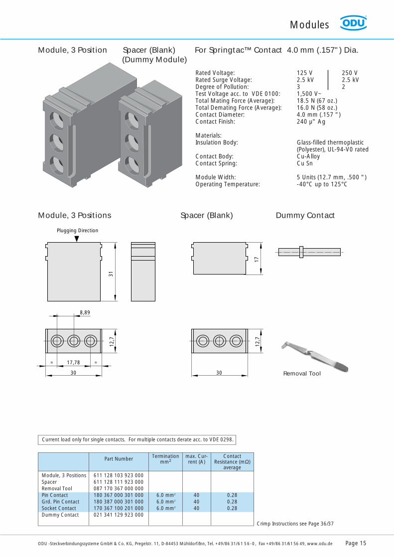
Rated Voltage: 125 V 250 VRated Surge Voltage: 2.5 kV 2.5 kVDegree of Pollution: 3 2Test Voltage acc. to VDE 0100: 1,500 V~Total Mating Force (Average): 18.5 N (67 oz.)Total Demating Force (Average): 16.0 N (58 oz.)Contact Diameter: 4.0 mm (.157 ")Contact Finish: 240 µ" Ag
Materials:Insulation Body: Glass-filled thermoplastic
(Polyester), UL-94-V0 ratedContact Body: Cu-AlloyContact Spring: Cu Sn
Module Width: 5 Units (12.7 mm, .500 ")Operating Temperature: -40°C up to 125°C
Module, 3 Position Spacer (Blank)(Dummy Module)
Module, 3 PositionsSpacerRemoval ToolPin ContactGrd. Pin ContactSocket ContactDummy Contact
611 128 103 923 000611 128 111 923 000087 170 367 000 000180 367 000 301 000180 387 000 301 000170 367 100 201 000021 341 129 923 000
6.0 mm2
6.0 mm2
6.0 mm2
max. Cur-rent (A)
Terminationmm2Part Number
404040
ContactResistance (mΩ)
average
0.280.280.28
31
8,89
17,78= =
30
12,7
17
30
12,7
Plugging Direction
Current load only for single contacts. For multiple contacts derate acc. to VDE 0298.
Module, 3 Positions Spacer (Blank) Dummy Contact
For Springtac™ Contact 4.0 mm (.157") Dia.
Crimp Instructions see Page 36/37
Removal Tool
Modules
Page 16 ODU -Steckverbindungssysteme GmbH & Co. KG, Pregelstr. 11, D-84453 Mühldorf/Inn, Tel. +49/86 31/61 56-0, Fax +49/86 31/61 56 49, www.odu.de
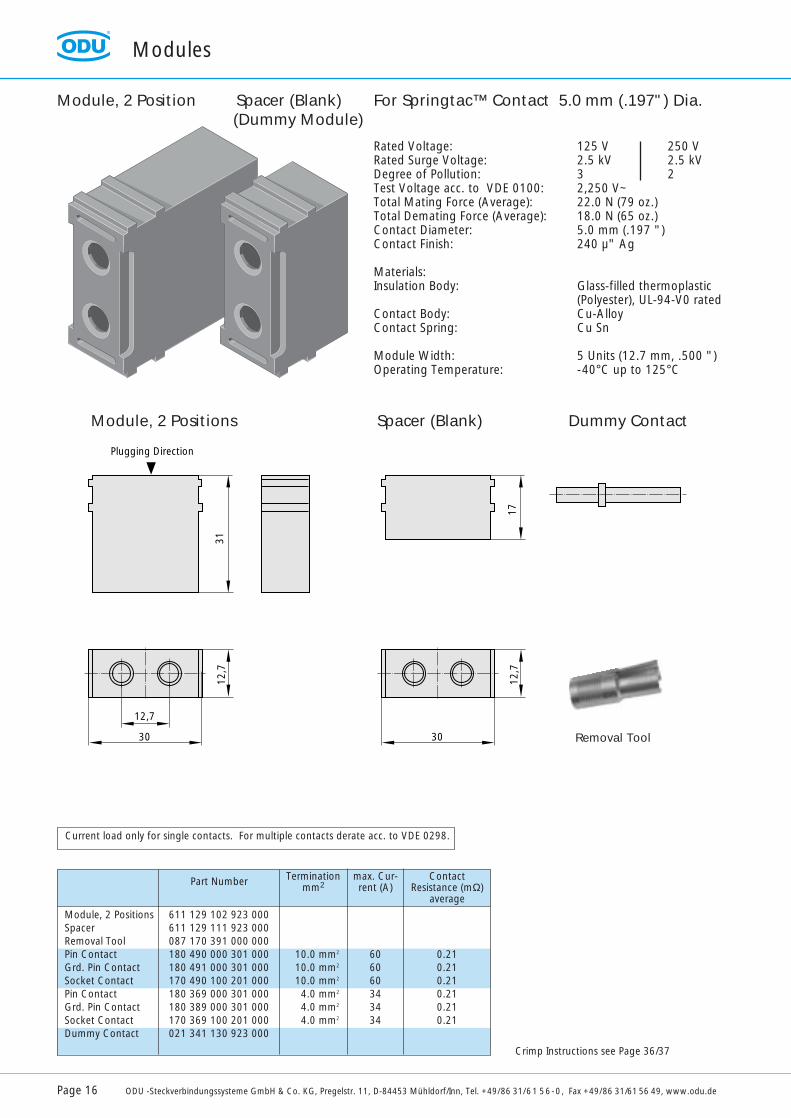
Rated Voltage: 125 V 250 VRated Surge Voltage: 2.5 kV 2.5 kVDegree of Pollution: 3 2Test Voltage acc. to VDE 0100: 2,250 V~Total Mating Force (Average): 22.0 N (79 oz.)Total Demating Force (Average): 18.0 N (65 oz.)Contact Diameter: 5.0 mm (.197 ")Contact Finish: 240 µ" Ag
Materials:Insulation Body: Glass-filled thermoplastic
(Polyester), UL-94-V0 ratedContact Body: Cu-AlloyContact Spring: Cu Sn
Module Width: 5 Units (12.7 mm, .500 ")Operating Temperature: -40°C up to 125°C
Module, 2 Position Spacer (Blank)(Dummy Module)
Module, 2 PositionsSpacerRemoval ToolPin ContactGrd. Pin ContactSocket ContactPin ContactGrd. Pin ContactSocket ContactDummy Contact
611 129 102 923 000611 129 111 923 000087 170 391 000 000180 490 000 301 000180 491 000 301 000170 490 100 201 000180 369 000 301 000180 389 000 301 000170 369 100 201 000021 341 130 923 000
10.0 mm2
10.0 mm2
10.0 mm2
4.0 mm2
4.0 mm2
4.0 mm2
max. Cur-rent (A)
Terminationmm2Part Number
606060343434
ContactResistance (mΩ)
average
0.210.210.210.210.210.21
31
12,7
30
12,7
17
30
12,7
Plugging Direction
Current load only for single contacts. For multiple contacts derate acc. to VDE 0298.
Module, 2 Positions Spacer (Blank) Dummy Contact
For Springtac™ Contact 5.0 mm (.197") Dia.
Removal Tool
Crimp Instructions see Page 36/37

For your notes
ODU -Steckverbindungssysteme GmbH & Co. KG, Pregelstr. 11, D-84453 Mühldorf/Inn, Tel. +49/86 31/61 56-0, Fax +49/86 31/61 56 49, www.odu.de Page 17
Modules
Page 18 ODU -Steckverbindungssysteme GmbH & Co. KG, Pregelstr. 11, D-84453 Mühldorf/Inn, Tel. +49/86 31/61 56-0, Fax +49/86 31/61 56 49, www.odu.de
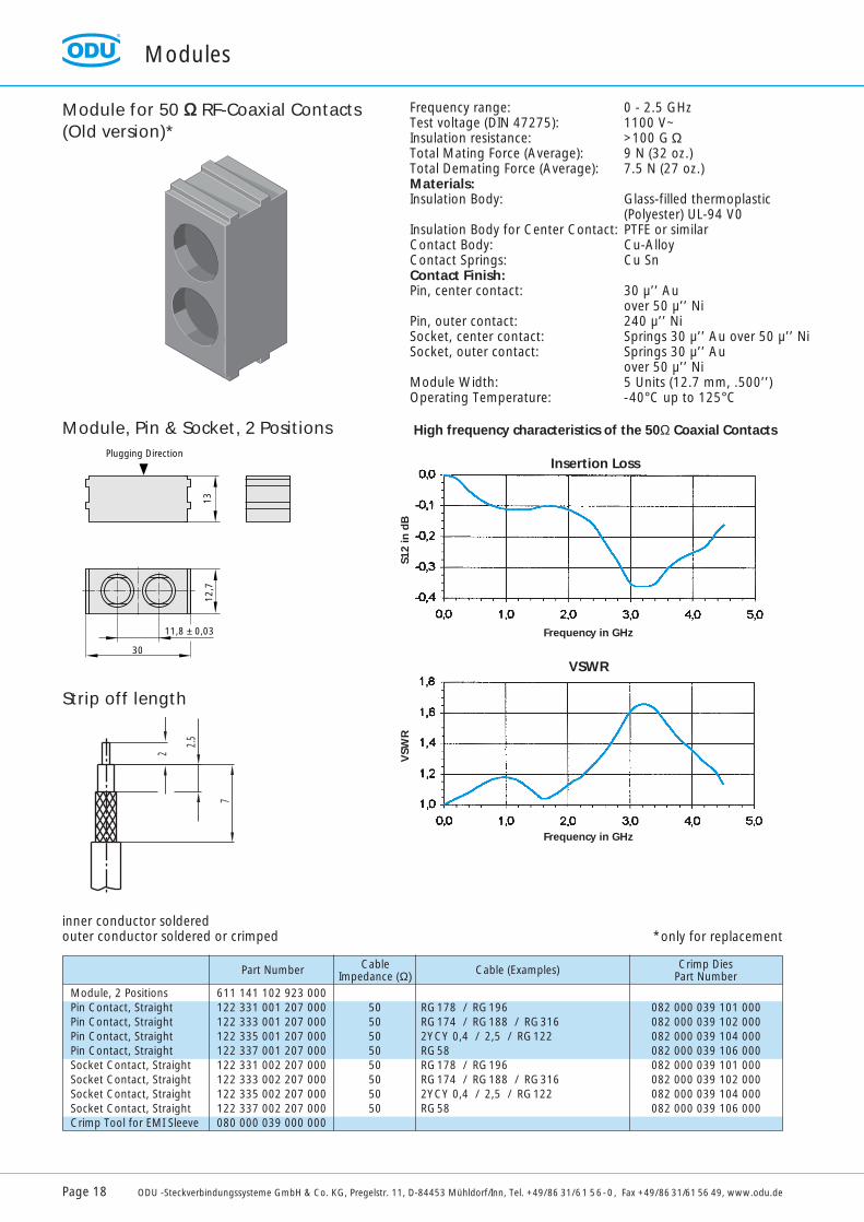
Module for 50 ΩΩ RF-Coaxial Contacts(Old version)*
Module, 2 PositionsPin Contact, StraightPin Contact, StraightPin Contact, StraightPin Contact, StraightSocket Contact, StraightSocket Contact, StraightSocket Contact, StraightSocket Contact, StraightCrimp Tool for EMI Sleeve
611 141 102 923 000122 331 001 207 000122 333 001 207 000122 335 001 207 000122 337 001 207 000122 331 002 207 000122 333 002 207 000122 335 002 207 000122 337 002 207 000080 000 039 000 000
Cable Impedance (Ω)Part Number
5050505050505050
Cable (Examples)
RG178 / RG196RG174 / RG188 / RG3162YCY 0,4 / 2,5 / RG122RG58RG178 / RG196RG174 / RG188 / RG3162YCY 0,4 / 2,5 / RG122RG58
Crimp DiesPart Number
082 000 039 101 000082 000 039 102 000082 000 039 104 000082 000 039 106 000082 000 039 101 000082 000 039 102 000082 000 039 104 000082 000 039 106 000
13
11,8 ± 0,03
30
Plugging Direction
12,7
2
7
2.5
Module, Pin & Socket, 2 Positions
Strip off length
Frequency range: 0 - 2.5 GHzTest voltage (DIN 47275): 1100 V~Insulation resistance: >100 G ΩTotal Mating Force (Average): 9 N (32 oz.)Total Demating Force (Average): 7.5 N (27 oz.)Materials:Insulation Body: Glass-filled thermoplastic
(Polyester) UL-94 V0Insulation Body for Center Contact: PTFE or similarContact Body: Cu-AlloyContact Springs: Cu SnContact Finish:Pin, center contact: 30 µ’’ Au
over 50 µ’’ NiPin, outer contact: 240 µ’’ NiSocket, center contact: Springs 30 µ’’ Au over 50 µ’’ NiSocket, outer contact: Springs 30 µ’’ Au
over 50 µ’’ NiModule Width: 5 Units (12.7 mm, .500’’)Operating Temperature: -40°C up to 125°C
High frequency characteristics of the 50Ω Coaxial Contacts
Insertion Loss
Frequency in GHz
VSWR
Frequency in GHz
VSW
RS1
2 in
dB
inner conductor solderedouter conductor soldered or crimped *only for replacement
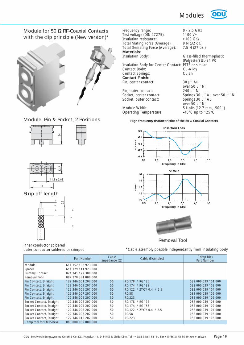
ModuleSpacerDummy ContactRemoval ToolPin Contact, StraightPin Contact, StraightPin Contact, StraightPin Contact, StraightPin Contact, StraightSocket Contact, StraightSocket Contact, StraightSocket Contact, StraightSocket Contact, StraightSocket Contact, StraightCrimp tool for EMI Sleeve
611 152 102 923 000611 129 111 923 000021 341 177 300 000087 170 391 000 000122 346 001 207 000122 346 003 207 000122 346 005 207 000122 346 007 207 000122 346 009 207 000122 346 002 207 000122 346 004 207 000122 346 006 207 000122 346 008 207 000122 346 010 207 000080 000 039 000 000
Cable Impedance (Ω)Part Number
50505050505050505050
Cable (Examples)
RG178 / RG196RG174 / RG188RG122 / 2YCY 0.4 / 2.5RG58RG223RG178 / RG196RG174 / RG188RG122 / 2YCY 0.4 / 2.5RG58RG223
Crimp DiesPart Number
082 000 039 101 000082 000 039 102 000082 000 039 104 000082 000 039 106 000082 000 039 106 000082 000 039 101 000082 000 039 102 000082 000 039 104 000082 000 039 106 000082 000 039 106 000
Modules
ODU -Steckverbindungssysteme GmbH & Co. KG, Pregelstr. 11, D-84453 Mühldorf/Inn, Tel. +49/86 31/61 56-0, Fax +49/86 31/61 56 49, www.odu.de Page 19
Module for 50 ΩΩ RF-Coaxial Contactswith the clip principle (New version)*
2
7
2.5
Module, Pin & Socket, 2 Positions
Strip off length
Frequency range: 0 - 2.5 GHzTest voltage (DIN 47275): 1100 V~Insulation resistance: >100 G ΩTotal Mating Force (Average): 9 N (32 oz.)Total Demating Force (Average): 7.5 N (27 oz.)Materials:Insulation Body: Glass-filled thermoplastic
(Polyester) UL-94 V0Insulation Body for Center Contact: PTFE or similarContact Body: Cu-AlloyContact Springs: Cu SnContact Finish:Pin, center contact: 30 µ’’ Au
over 50 µ’’ NiPin, outer contact: 240 µ’’ NiSocket, center contact: Springs 30 µ’’ Au over 50 µ’’ NiSocket, outer contact: Springs 30 µ’’ Au
over 50 µ’’ NiModule Width: 5 Units (12.7 mm, .500’’)Operating Temperature: -40°C up to 125°C
High frequency characteristics of the 50 Ω Coaxial Contacts
Insertion Loss
Frequency in GHz
VSWR
Frequency in GHz
VSW
RS1
2 in
dB
inner conductor solderedouter conductor soldered or crimped
Removal Tool
2412
,7
30
11,8 ± 0,03
*Cable assembly possible independantly from insulating body
0.0 0.2 0.4 0.6
1.8
1.6
1.4
1.2
1.0
0.0 0.2 0.4 0.6
0.0
-0.1
-0.2
-0.3
-0.4
-0.5
Modules
Page 20 ODU -Steckverbindungssysteme GmbH & Co. KG, Pregelstr. 11, D-84453 Mühldorf/Inn, Tel. +49/86 31/61 56-0, Fax +49/86 31/61 56 49, www.odu.dePage 20 ODU -Steckverbindungssysteme GmbH & Co. KG, Pregelstr. 11, D-84453 Mühldorf/Inn, Tel. +49/86 31/61 56-0, Fax +49/86 31/61 56 49, www.odu.de
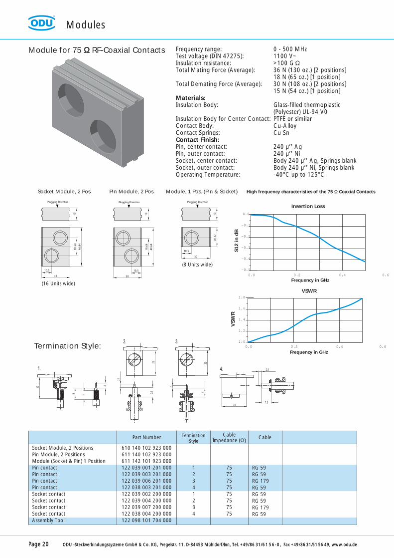
Module for 75 ΩΩ RF-Coaxial Contacts
13
10,5
30
18,6
4
40,6
4
Plugging Direction
13
10,5
30
18,6
4
40,6
4
Plugging Direction
13
10,5
30
20,3
2
Plugging Direction
Socket Module, 2 Pos. Pin Module, 2 Pos. Module, 1 Pos. (Pin & Socket) High frequency characteristics of the 75 Ω Coaxial Contacts
Termination Style:
(16 Units wide)
(8 Units wide)
Insertion Loss
VSWR
Frequency in GHz
Frequency in GHz
S12
in d
BV
SWR
Socket Module, 2 PositionsPin Module, 2 PositionsModule (Socket & Pin) 1 PositionPin contactPin contactPin contactPin contactSocket contactSocket contactSocket contactSocket contactAssembly Tool
610 140 102 923 000611 140 102 923 000611 142 101 923 000122 039 001 201 000122 039 003 201 000122 039 006 201 000122 038 003 201 000122 039 002 200 000122 039 004 200 000122 039 007 200 000122 038 004 200 000122 098 101 704 000
12341234
CableImpedance (Ω)
TerminationStyle
Part Number
7575757575757575
Cable
RG 59 RG 59 RG 179 RG 59 RG 59 RG 59 RG 179 RG 59
Frequency range: 0 - 500 MHzTest voltage (DIN 47275): 1100 V~Insulation resistance: >100 G ΩTotal Mating Force (Average): 36 N (130 oz.) [2 positions]
18 N (65 oz.) [1 position]Total Demating Force (Average): 30 N (108 oz.) [2 positions]
15 N (54 oz.) [1 position]Materials:Insulation Body: Glass-filled thermoplastic
(Polyester) UL-94 V0Insulation Body for Center Contact: PTFE or similarContact Body: Cu-AlloyContact Springs: Cu SnContact Finish:Pin, center contact: 240 µ’’ AgPin, outer contact: 240 µ’’ NiSocket, center contact: Body 240 µ’’ Ag, Springs blankSocket, outer contact: Body 240 µ’’ Ni, Springs blankOperating Temperature: -40°C up to 125°C
17
4
79
1.
20
2.5
7.5
20
2
7
2. 3.
20
2.5
7.5
4.
Modules
ODU -Steckverbindungssysteme GmbH & Co. KG, Pregelstr. 11, D-84453 Mühldorf/Inn, Tel. +49/86 31/61 56-0, Fax +49/86 31/61 56 49, www.odu.de Page 21
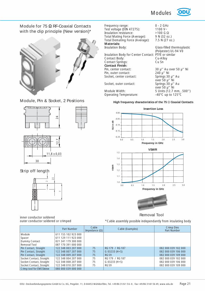
Module for 75 ΩΩ RF-Coaxial Contactswith the clip principle (New version)*
2
7
2.5
Module, Pin & Socket, 2 Positions
Strip off length
Frequency range: 0 - 2 GHzTest voltage (DIN 47275): 1100 V~Insulation resistance: >100 G ΩTotal Mating Force (Average): 9 N (32 oz.)Total Demating Force (Average): 7.5 N (27 oz.)Materials:Insulation Body: Glass-filled thermoplastic
(Polyester) UL-94 V0Insulation Body for Center Contact: PTFE or similarContact Body: Cu-AlloyContact Springs: Cu SnContact Finish:Pin, center contact: 30 µ’’ Au over 50 µ’’ NiPin, outer contact: 240 µ’’ NiSocket, center contact: Springs 30 µ’’ Au
over 50 µ’’ NiSocket, outer contact: Springs 30 µ’’ Au
over 50 µ’’ NiModule Width: 5 Units (12.7 mm, .500’’)Operating Temperature: -40°C up to 125°C
High frequency characteristics of the 75 Ω Coaxial Contacts
Insertion Loss
Frequency in GHz
VSWR
Frequency in GHz
VSW
RS1
2 in
dB
0.0 0.5 1.0 1.5 2.0 2.5 3.0
0.00
-0.05
-0.10
-0.15
-0.20
0.0 0.5 1.0 1.5 2.0 2.5 3.0
1.5
1.4
1.3
1.2
1.1
1.0
inner conductor solderedouter conductor soldered or crimped
Removal Tool
ModuleSpacerDummy ContactRemoval ToolPin Contact, StraightPin Contact, StraightPin Contact, StraightSocket Contact, StraightSocket Contact, StraightSocket Contact, StraightCrimp tool for EMI Sleeve
611 155 102 923 000611 129 111 923 000021 341 179 300 000087 170 391 000 000122 348 003 207 000122 348 007 207 000122 348 009 207 000122 348 004 207 000122 348 008 207 000122 348 010 207 000080 000 039 000 000
Cable Impedance (Ω)Part Number
757575757575
Cable (Examples)
RG179 / RG187G 03233 (H+S)RG59RG179 / RG187G 03233 (H+S)RG59
Crimp DiesPart Number
082 000 039 102 000082 000 039 106 000082 000 039 109 000082 000 039 102 000082 000 039 106 000082 000 039 109 000
2412
,7
30
11,8 ± 0,03
*Cable assembly possible independantly from insulating body

Modules
Page 22 ODU -Steckverbindungssysteme GmbH & Co. KG, Pregelstr. 11, D-84453 Mühldorf/Inn, Tel. +49/86 31/61 56-0, Fax +49/86 31/61 56 49, www.odu.de
Module for compressed air valveTube Ø max. 4 mm
Materials:Insulation Body: Glass-filled thermoplastic
(Polyester) UL-94 V0 ratedCompressed Air Valve: Cu-AlloyContact Finish: blankAir Pressure: shut off max. 4 bar
not shut off max. 6 barOperating Temperature: -40°C up to 125°C
Drop of pressure (bar)
Flo
wra
te (
l/m
in)
0.1 0.2 0.3 0.4 0.5 0.6
100
90
80
70
60
50
40
30
20
10
0
13
11,8 ± 0,03
30
Plugging Direction
12,7
Module, Pin & Socket, 2 Positions plug sleeve coupling plug
for different kind of termination:
13 13
A
X
A
Socket Module, 2 PositionsPlug Sleeve (not shut off)Plug Sleeve (not shut off)Plug Sleeve (not shut off)Coupling Plug (not shut off)Coupling Plug (not shut off)Coupling Plug (not shut off)Coupling Plug (shut off)Coupling Plug (shut off)
611 141 102 923 000196 023 001 300 000196 024 001 300 000196 025 001 300 000196 023 003 300 000196 024 003 300 000196 025 003 300 000196 023 002 300 000196 024 002 300 000
34
M534
M534
Size XSize AØ
Part Number
8.510.5
8.510.5
8.510.5
both side “shut off version” on request
13
10,5
30
Plugging Direction
18,6
4
40,6
4
13
10,5
30
Plugging Direction
18,6
4
40,6
4
Couppling Plug Plug sleeve
X 13 X13
Ø A
13
10,5
30
Plugging Direction
20,3
2
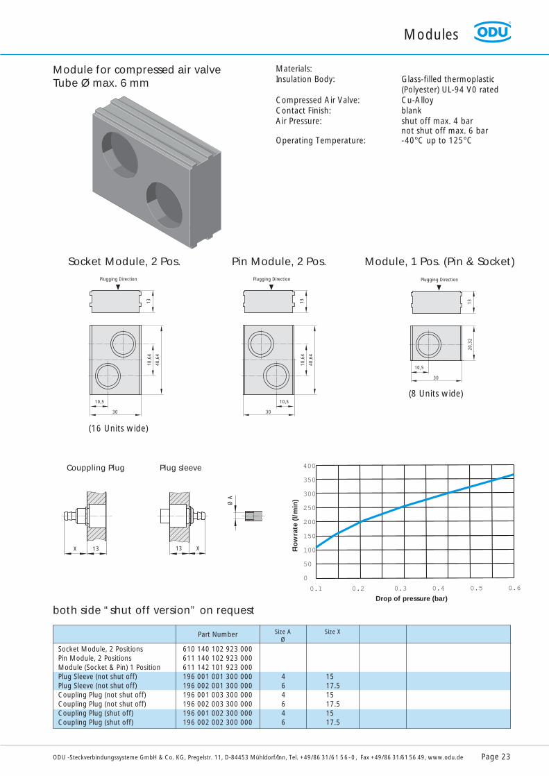
Materials:Insulation Body: Glass-filled thermoplastic
(Polyester) UL-94 V0 ratedCompressed Air Valve: Cu-AlloyContact Finish: blankAir Pressure: shut off max. 4 bar
not shut off max. 6 barOperating Temperature: -40°C up to 125°C
Module for compressed air valveTube Ø max. 6 mm
Socket Module, 2 Pos. Pin Module, 2 Pos. Module, 1 Pos. (Pin & Socket)
(16 Units wide)
(8 Units wide)
Drop of pressure (bar)
Flo
wra
te (
l/m
in)
0.1 0.2 0.3 0.4 0.5 0.6
400
350
300
250
200
150
100
50
0
Socket Module, 2 PositionsPin Module, 2 PositionsModule (Socket & Pin) 1 PositionPlug Sleeve (not shut off)Plug Sleeve (not shut off)Coupling Plug (not shut off)Coupling Plug (not shut off)Coupling Plug (shut off)Coupling Plug (shut off)
610 140 102 923 000611 140 102 923 000611 142 101 923 000196 001 001 300 000196 002 001 300 000196 001 003 300 000196 002 003 300 000196 001 002 300 000196 002 002 300 000
464646
Size XSize AØ
Part Number
1517.51517.51517.5
Modules
ODU -Steckverbindungssysteme GmbH & Co. KG, Pregelstr. 11, D-84453 Mühldorf/Inn, Tel. +49/86 31/61 56-0, Fax +49/86 31/61 56 49, www.odu.de Page 23
both side “shut off version” on request
Modules
Page 24 ODU -Steckverbindungssysteme GmbH & Co. KG, Pregelstr. 11, D-84453 Mühldorf/Inn, Tel. +49/86 31/61 56-0, Fax +49/86 31/61 56 49, www.odu.de
Part Number
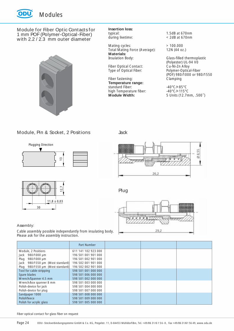
Insertion loss:typical: 1.5dB at 670nmduring livetime: < 2dB at 670nm
Mating cycles: > 100.000Total Mating Force (Average): 12N (44 oz.)Materials:Insulation Body: Glass-filled thermoplastic
(Polyester) UL-94 V0Fiber Optical Contact: Cu-Ni-Zn AlloyType of Optical Fiber: Polymer-Optical-Fiber
(POF) 980/1000 or 980/1550Fiber fastening: ClampingTemperature range:standard Fiber: -40°C/+85°Chigh Temperature fiber: -40°C/+115°CModule Width: 5 Units (12.7mm, .500´´)
Module, 2 Positions 611 141 102 923 000Jack 980/1000 µm 196 501 001 901 000Plug 980/1000 µm 196 501 002 901 000Jack 980/1550 µm (Most standard) 196 502 001 901 000Plug 980/1550 µm (Most standard) 196 502 002 901 000Tool for cable-stripping 598 501 001 000 000Spare blades 598 501 006 000 000Wrench/Spanner 4.5 mm 598 501 002 000 000Wrench/box spanner 8 mm 598 501 003 000 000Polish-device for jack 598 501 004 000 000Polish-device for plug 598 501 007 000 000Sandpaper 1000 598 501 008 000 000Polishfleece 598 501 009 000 000Polish for acrylic glass 598 501 005 000 000
Module for Fiber Optic Contacts for 1 mm POF (Polymer-Optical-Fiber)with 2.2 / 2.3 mm outer diameter
Jack
Plug
13
11,8 ± 0,03
30
Plugging Direction
12,7
Module, Pin & Socket, 2 Positions
Fiber optical contact for glass fiber on request
Assembly:
Cable assembly possible independantly from insulating body.Please ask for the assembly instruction.

Frame for Pin Contacts, with Guide PinsFrame for Sockets, without Guide Pins
ODU-MAC-S Aluminum FrameStandard version
Part Numbers for Frame PartsPlease assemble the part numbers as follows:
x = Number of Modules Maß l = x · y + z (l max. = 152,5 mm for 60 Units)y = Width of Modules; Maß L = l + 30z = Center Module = 12.7 mm (.500") (optional)Order Example:Frame with guide pins with l = 127.1 mm has 50 units at 2.54 mm each.( X = Length of guide pins)
611 020 050 600 000; X = 10611 021 050 600 000; X = 12,5611 050 050 600 000; X = 10 with labeling611 025 050 600 000; X = 21 locking spindle
Frame without guide pins with l = 127,1 mm has 50 units at 2.54 mm each.610 020 050 600 000611 050 050 600 000 ( with labeling)
Individual frame parts are available on request.
Ø 5Ø 4Ø 3Ø 2,41Ø 2Ø 1,5Ø 1,02Ø 0,76
8
L *) L1
L *) = First-Make Ground Pin6
Ø 76Ø 1,02Ø 1,5Ø 2Ø 2,41Ø 3Ø 4Ø 5
1010
21 m
ax.
2
L *) L1
Pin Ø
Socket Contact Ø
5,5
8,5
15 l
L37
Ø 8,5
End Piece Left End Piece Right
z
Center Piece withLocking Module
(On Request)
X
Guide Pins(only for self-centering)
Ø 4
,3
3,5
Centering Socketaxial free space: 0,2radial free space: 0,6(parts are deliveredloose)
5,5
8,5
15 l
L
37
Ø 4,3
z
End Piece Left End Piece Right
Center Piece withLocking Module
(On Request)
Aluminium Frame
ODU -Steckverbindungssysteme GmbH & Co. KG, Pregelstr. 11, D-84453 Mühldorf/Inn, Tel. +49/86 31/61 56-0, Fax +49/86 31/61 56 49, www.odu.de Page 25
Aluminum Frame
Page 26 ODU -Steckverbindungssysteme GmbH & Co. KG, Pregelstr. 11, D-84453 Mühldorf/Inn, Tel. +49/86 31/61 56-0, Fax +49/86 31/61 56 49, www.odu.de
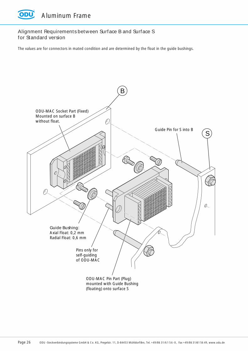
Alignment Requirements between Surface B and Surface Sfor Standard version
The values are for connectors in mated condition and are determined by the float in the guide bushings.
ODU-MAC Socket Part (Fixed)Mounted on surface Bwithout float.
Guide Bushing:Axial Float: 0,2 mmRadial Float: 0,6 mm
Pins only forself-guidingof ODU-MAC
ODU-MAC Pin Part (Plug)mounted with Guide Bushing(floating) onto surface S
Guide Pin for S into B
B
S

ODU-MAC-L Aluminum FrameSpecial Design with longer guide pins and -bushes for higher mating cycles and bigger radial offset.
32 Keying Positions possible - please request
A B
C D
E F
G H
I K
37
18
208
38
34 +
1
6
(Number of Units at 2,54 +34) +0,2-0
max. R
3
M4
Mounting area
Guide Plane Steel Socket
Application Example
Axial tolerances 0.4 mm, Radial tolerances ± 1.2 mm
Panel Cut-Out
Contact Plane
For examplesee page 58
Aluminum Frame
ODU -Steckverbindungssysteme GmbH & Co. KG, Pregelstr. 11, D-84453 Mühldorf/Inn, Tel. +49/86 31/61 56-0, Fax +49/86 31/61 56 49, www.odu.de Page 27
L+ 46
Pin Frame (Plug)Frame for Sockets (Receptacle)
Part Number611 009 0XX 600 000611 009 0XX 600 000
Additional Ordering InformationDim. L = Numbers of units x 2.54.XX = Denotes number of units

Aluminum Frame
Page 28 ODU -Steckverbindungssysteme GmbH & Co. KG, Pregelstr. 11, D-84453 Mühldorf/Inn, Tel. +49/86 31/61 56-0, Fax +49/86 31/61 56 49, www.odu.de
Pin Frame (Plug) 611 017 0XX 600 000Dim. L = Number of units x 2.54,XX = Denotes number of units
Additional Ordering InformationPart Number
Frame for Sockets(Receptacle) 610 017 0XX 600 000
Dim. L = Number of units x 2.54 mmXX = Denotes number of units
Additional Ordering InformationPart Number
ODU-MAC-M Frame for Pins (Plug)for reduced layout
ODU-MAC-M Frame for Sockets (Receptacle)for reduced layout
37
L
L +
13
Ø 3,210-0,110
37
L
L +
13
Ø 3,210
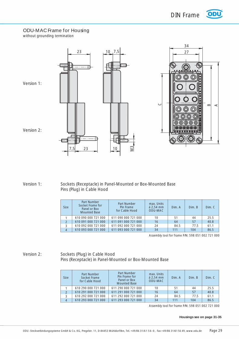
ODU-MAC Frame for Housingwithout grounding termination
1234
Size Dim. A
610 090 000 721 000610 091 000 721 000610 092 000 721 000610 093 000 721 000
611 090 000 721 000611 091 000 721 000611 092 000 721 000611 093 000 721 000
Part NumberSocket Frame for
Panel or Box Mounted Base
Part NumberPin Frame
for Cable Hood
10162434
516484.5
111
445777.5
104
25.540.861.186.5
Dim. B Dim. Cmax. Unitsá 2,54 mmODU-MAC
Assembly tool for frame P/N: 598 051 002 721 000
1234
Size Dim. A
610 290 000 721 000610 291 000 721 000610 292 000 721 000610 293 000 721 000
611 290 000 721 000611 291 000 721 000611 292 000 721 000611 293 000 721 000
Part NumberSocket Frame
for Cable Hood
Part NumberPin Frame forPanel or Box
Mounted Base 10162434
516484.5
111
445777.5
104
25.540.861.186.5
Dim. B Dim. Cmax. Unitsá 2,54 mmODU-MAC
Assembly tool for frame P/N: 598 051 002 721 000
DIN Frame
ODU -Steckverbindungssysteme GmbH & Co. KG, Pregelstr. 11, D-84453 Mühldorf/Inn, Tel. +49/86 31/61 56-0, Fax +49/86 31/61 56 49, www.odu.de Page 29
Version 1: Sockets (Receptacle) in Panel-Mounted or Box-Mounted BasePins (Plug) in Cable Hood
Version 2: Sockets (Plug) in Cable HoodPins (Receptacle) in Panel-Mounted or Box-Mounted Base
10 7,5
7,5 23 10 M3
27
34
C B A
23
Version 1:
Version 2:
Housings see on page 31-35
DIN Frame
Page 30 ODU -Steckverbindungssysteme GmbH & Co. KG, Pregelstr. 11, D-84453 Mühldorf/Inn, Tel. +49/86 31/61 56-0, Fax +49/86 31/61 56 49, www.odu.de
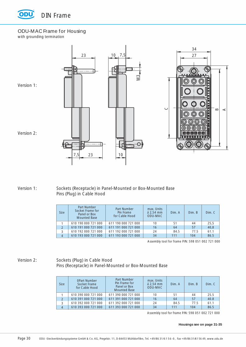
ODU-MAC Frame for Housingwith grounding termination
1234
Size Dim. A
610 390 000 721 000610 391 000 721 000610 392 000 721 000610 393 000 721 000
611 390 000 721 000611 391 000 721 000611 392 000 721 000611 393 000 721 000
0Part NumberSocket Frame
for Cable Hood
Part NumberPin Frame forPanel or Box
Mounted Base 10162434
516484.5
111
445777.5
104
25.540.861.186.5
Dim. B Dim. Cmax. Unitsá 2,54 mmODU-MAC
Assembly tool for frame P/N: 598 051 002 721 000
Version 1: Sockets (Receptacle) in Panel-Mounted or Box-Mounted BasePins (Plug) in Cable Hood
Version 2: Sockets (Plug) in Cable HoodPins (Receptacle) in Panel-Mounted or Box-Mounted Base
10 7,5
M3
C B A
27
34
7,5 23 10
23
Version 1:
Version 2:
Housings see on page 31-35
1234
Size Dim. A
610 190 000 721 000610 191 000 721 000610 192 000 721 000610 193 000 721 000
611 190 000 721 000611 191 000 721 000611 192 000 721 000611 193 000 721 000
Part NumberSocket Frame for
Panel or Box Mounted Base
Part NumberPin Frame
for Cable Hood
10162434
516484.5
111
445777.5
104
25,540,861.186.5
Dim. B Dim. Cmax. Unitsá 2,54 mmODU-MAC
Assembly tool for frame P/N: 598 051 002 721 000
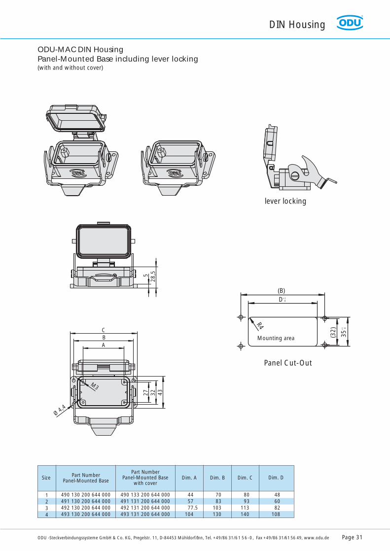
ODU-MAC DIN HousingPanel-Mounted Base including lever locking(with and without cover)
1234
Size Dim. A
490 130 200 644 000491 130 200 644 000492 130 200 644 000493 130 200 644 000
490 133 200 644 000491 131 200 644 000492 131 200 644 000493 131 200 644 000
Part NumberPanel-Mounted Base
Part NumberPanel-Mounted Base
with cover
445777.5
104
7083
103130
8093
113140
Dim. B Dim. C Dim. D
486082
108
DIN Housing
ODU -Steckverbindungssysteme GmbH & Co. KG, Pregelstr. 11, D-84453 Mühldorf/Inn, Tel. +49/86 31/61 56-0, Fax +49/86 31/61 56 49, www.odu.de Page 31
R R
528
,5
CBA
M3
Ø 4,4
27 32 43
lever locking
Panel Cut-Out
Mounting area (32)
35+
1 0
D+10
(B)
R4
Page 32 ODU -Steckverbindungssysteme GmbH & Co. KG, Pregelstr. 11, D-84453 Mühldorf/Inn, Tel. +49/86 31/61 56-0, Fax +49/86 31/61 56 49, www.odu.de
DIN Housing
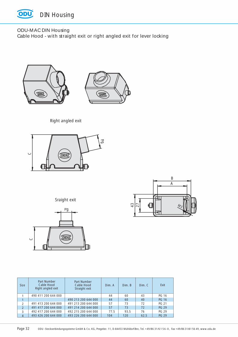
Right angled exit
ODU-MAC DIN HousingCable Hood - with straight exit or right angled exit for lever locking
RR
C
Pg
R
Pg
C
R
43 27
BA
M3
Sraight exit
112234
Size Dim. A
490 411 200 644 000
491 413 200 644 000491 417 200 644 000492 417 200 644 000493 426 200 644 000
490 213 200 644 000491 213 200 644 000491 214 200 644 000492 215 200 644 000493 226 200 644 000
Part NumberCable Hood
Right angled exit
Part NumberCable HoodStraight exit
4444575777.5
104
6060737393.5
120
434072727662.5
Dim. B Dim. C Exit
PG 16PG 16PG 21PG 29PG 29PG 29
DIN Housing
ODU -Steckverbindungssysteme GmbH & Co. KG, Pregelstr. 11, D-84453 Mühldorf/Inn, Tel. +49/86 31/61 56-0, Fax +49/86 31/61 56 49, www.odu.de Page 33
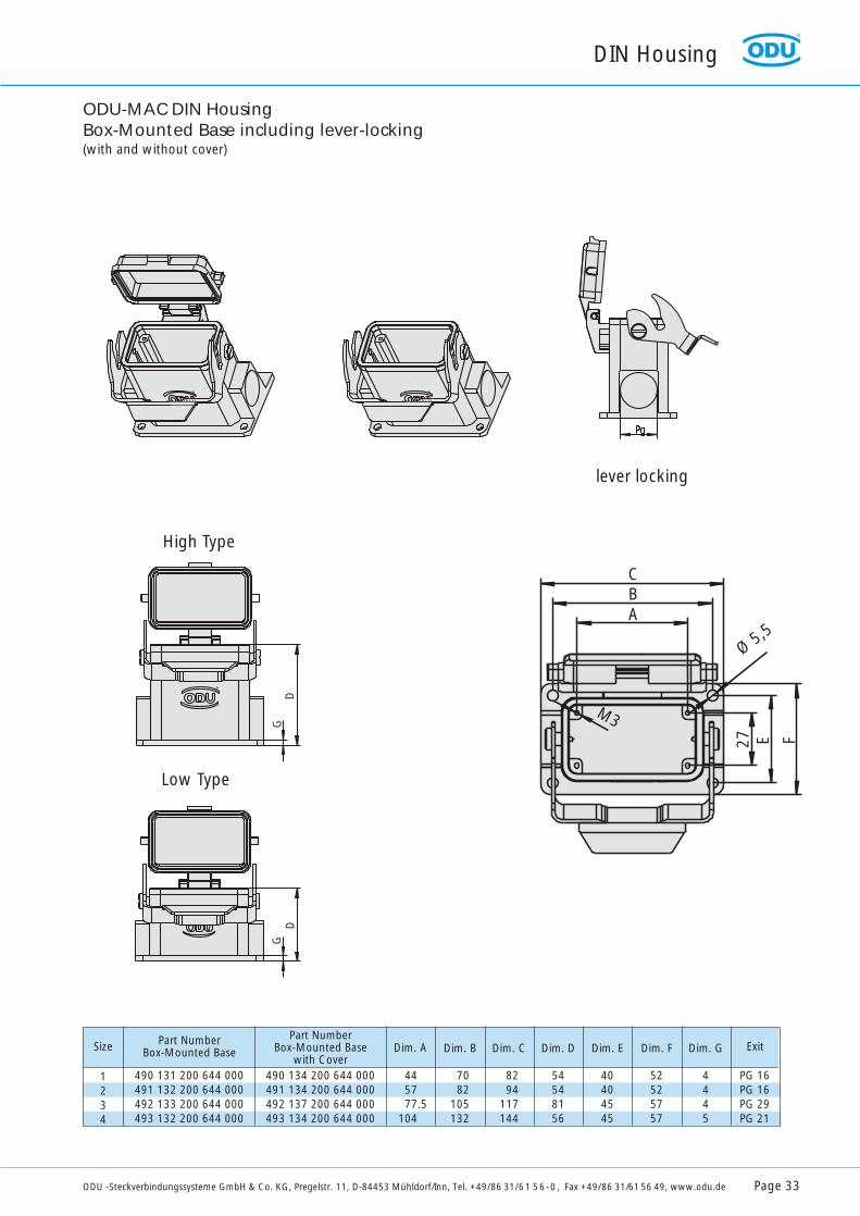
1234
Size Dim. A
490 131 200 644 000491 132 200 644 000492 133 200 644 000493 132 200 644 000
490 134 200 644 000491 134 200 644 000492 137 200 644 000493 134 200 644 000
Part NumberBox-Mounted Base
Part NumberBox-Mounted Base
with Cover445777.5
104
Dim. B
7082
105132
Dim. C
8294
117144
Dim. D
54548156
Dim. E
40404545
Dim. F
52525757
Dim. G
4445
Exit
PG 16PG 16PG 29PG 21
ODU-MAC DIN Housing Box-Mounted Base including lever-locking(with and without cover)
GD
GD
R
R R
CBA
M3
Ø 5,5
27 E F
lever locking
High Type
Low Type

DIN Housing
Page 34 ODU -Steckverbindungssysteme GmbH & Co. KG, Pregelstr. 11, D-84453 Mühldorf/Inn, Tel. +49/86 31/61 56-0, Fax +49/86 31/61 56 49, www.odu.de
ODU-MAC DIN Housingfor Spindle Locking
R
R
R
AB
D
C
Ø 4,5
R
R
AB
D
C
Ø 4,5
R
R
B
35+
1
A+1
27
R4
Cable Hood
Panel-MountedBase
Cable Hood
Box-Mounted Base
Size234
Dim. A6082108
Dim. B83103130
Panel-Cut-out
mounting area
2234
Size Dim. A
613 091 013 644 000613 091 014 644 000613 092 014 644 000613 093 014 644 000
612 091 010 644 000612 091 010 644 000612 092 010 644 000612 093 010 644 000
Part NumberCable Hood
Part NumberPanel-Mounted Base
51727676
Dim. B
29292929
Dim. C
32323232
Dim. D
8383103130
Exit
PG 21PG 29PG 29PG 29
2234
Size Dim. A
613 091 013 644 000613 091 014 644 000613 092 014 644 000613 093 014 644 000
612 091 022 644 000612 091 010 644 000612 092 024 644 000612 093 023 644 000
Part NumberCable Hood
Part NumberBox-Mounted Base
51727676
Dim. B
57576464
Dim. C
40404545
Dim. D
8282105132
Exit
PG 21PG 29PG 29PG 29

DIN-Housing
ODU -Steckverbindungssysteme GmbH & Co. KG, Pregelstr. 11, D-84453 Mühldorf/Inn, Tel. +49/86 31/61 56-0, Fax +49/86 31/61 56 49, www.odu.de Page 35
ODU-MAC Spindle Locking System, Version 1For Sockets (Receptacle) in Panel- or Box-Mounted Base and Pins (Plug) in Cable Hood.
ODU-MAC Spindle Locking System, Version 2For Sockets (Plug) in Cable Hood and Pins (Receptacle) in Panel- or Box-Mounted Base.
Center Module Locking Spindle
Center Module Locking Spindle
234
Size
615 091 001 721 000615 093 001 721 000615 093 001 721 000
614 090 001 304 000614 090 001 304 000614 090 001 304 000
Locking Spindlein Cable Hood
Center Module forPanel or Box Mounted Base
234
Size
615 091 002 721 000615 093 002 721 000615 093 002 721 000
614 090 002 304 000614 090 002 304 000614 090 002 304 000
Locking Spindlein Cable Hood
Center Module forPanel or Box Mounted Base
Version 1 Version 2
Space requirement: 5 units (5 x 2,54 mm)
Crimp Tools
Page 36 ODU -Steckverbindungssysteme GmbH & Co. KG, Pregelstr. 11, D-84453 Mühldorf/Inn, Tel. +49/86 31/61 56-0, Fax +49/86 31/61 56 49, www.odu.de
AWG
24/28
22
20/22
18
16
14
12
mm2
0.08/0.25
0.38
0.38/0.50
1
1.5
2.5
4
610
Contact
Ø
0.76
1.02
1.5
0.76
1.02
1.5
2.41
3
1.5
2.41
3
1.5
1.5
2.41
3
2.41
2.41
3
3
5
4
5
4 +0.5
4 +0.5
4 +0.5
5 +0.5
4 +0.5
5 +0.5
4 +0.5
4 +0.5
5 +0.5
5 +0.5
5 +0.5
4 +0.5
6 +0.5
6 +0.5
9 +0.5
>0.65 <0.70
021 345 151 300 000
021 345 152 300 000
021 345 153 300 000
>0.65 <0.70
021 345 151 300 000
>0.90 <0.95
021 345 152 300 000
021 345 153 300 000
021 345 149 300 000
021 345 150 300 000
>1.1 <1.15
021 345 153 300 000
021 345 149 300 000
021 345 150 300 000
>1.40 <1.45
021 345 153 300 000
>1.40 <1.45
021 345 153 300 000
021 345 149 300 000
021 345 150 300 000
>1.60 <1.65
021 345 149 300 000
021 345 150 300 000
080 000 014 000 000
Gauge Ø
Contact Holder
080 000 032 000 000
Gauge Ø
Contact Holder
080 000 037 000 000
Position no.
Contact Holder
>0.65 <0.70
021 345 151 300 000
021 345 152 300 000
021 345 153 300 000
>0.65 <0.70
021 345 151 300 000
>0.90 <0.95
021 345 152 300 000
021 345 153 300 000
021 345 149 300 000
021 345 150 300 000
>1.1 <1.15
021 345 153 300 000
021 345 149 300 000
021 345 150 300 000
>1.40 <1.45
021 345 153 300 000
>1.40 <1.45
021 345 153 300 000
021 345 149 300 000
021 345 150 300 000
>1.60 <1.65
021 345 149 300 000
021 345 150 300 000
4
021 345 151 200 037
021 345 152 200 037
021 345 153 200 037
4
021 345 151 200 037
7
021 345 152 200 037
021 345 153 200 037
0
1
2
0
1
2
3
4
2
3
4
2
2
3
4
3
4
0
1
2
0
1
2
3
4
2
3
4
2
2
3
4
3
4
Termination cross section strip
-off
leng
th
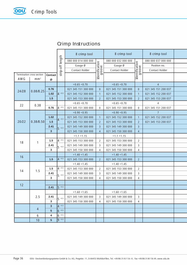
Crimp Instructions
8 crimp tool8 crimp tool 8 crimp tool
Iden
tific
atio
ngr
oove
Iden
tific
atio
ngr
oove
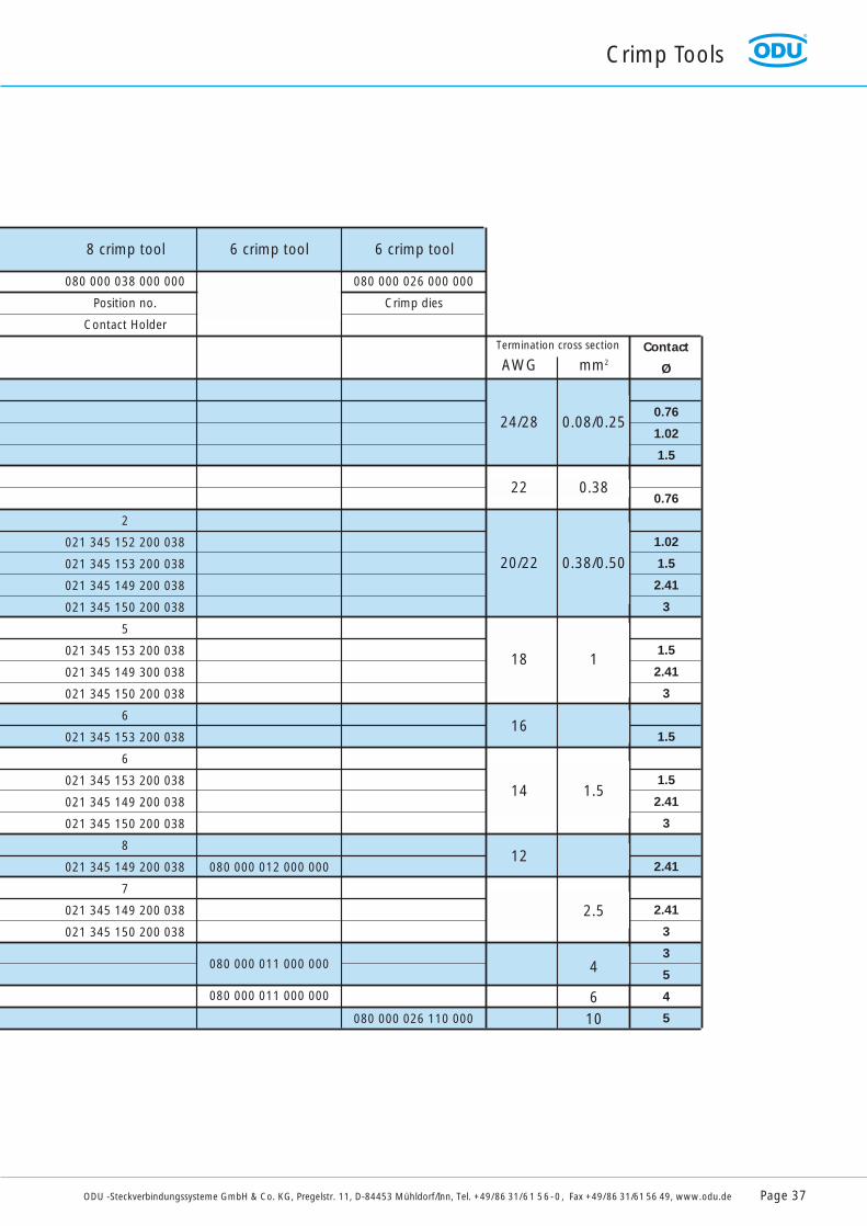
Crimp Tools
ODU -Steckverbindungssysteme GmbH & Co. KG, Pregelstr. 11, D-84453 Mühldorf/Inn, Tel. +49/86 31/61 56-0, Fax +49/86 31/61 56 49, www.odu.de Page 37
AWG
24/28
22
20/22
18
16
14
12
mm2
0.08/0.25
0.38
0.38/0.50
1
1.5
2.5
4
610
Contact
Ø
0.76
1.02
1.5
0.76
1.02
1.5
2.41
3
1.5
2.41
3
1.5
1.5
2.41
3
2.41
2.41
3
3
5
4
5
080 000 038 000 000
Position no.
Contact Holder
080 000 026 000 000
Crimp dies
2
021 345 152 200 038
021 345 153 200 038
021 345 149 200 038
021 345 150 200 038
5
021 345 153 200 038
021 345 149 300 038
021 345 150 200 038
6
021 345 153 200 038
6
021 345 153 200 038
021 345 149 200 038
021 345 150 200 038
8
021 345 149 200 038
7
021 345 149 200 038
021 345 150 200 038
080 000 012 000 000
080 000 011 000 000
080 000 011 000 000
080 000 026 110 000
Termination cross section
8 crimp tool 6 crimp tool 6 crimp tool

Order Number: 080 000 037 000 000
Order Number: 080 000 038 000 000
Crimp Tools
Page 38 ODU -Steckverbindungssysteme GmbH & Co. KG, Pregelstr. 11, D-84453 Mühldorf/Inn, Tel. +49/86 31/61 56-0, Fax +49/86 31/61 56 49, www.odu.de
Crimp Tools and Contact PreparationCrimping creates an easy, reliable, corrosion-free, and long-term connection between conductor andcontact. It requires little skill and can be performed by non-experts.
Crimping causes cold-flow of the conductor and contact material creating a gas-tight connection between contact and conductor. A stiffening of the conductor at the connection, as it is possible with soldering, can not occur. Crimping can be performed on very small or very large conductor crosssections.
For smaller cross sections (0.5 - 2.5 mm2) an industry-standard 8-point crimp tool is used. Larger cross sections require a hexagonal crimp press. For very large cross section the crimp procedure has to be done in several steps to assure good cold-flow of the conductor material and to avoid a brittleconnection.
8-Crimp Tool. Adjustable for cross section from 0.08 - 0.5 mm 2 (AWG28 - AWG20)Table for adjustment and Contact holder = positioner - see page 36/37
8-Crimp Tool. Adjustable for cross section from 0.38 - 2.5 mm 2 (AWG22 - AWG12)Table for adjustment and Contact holder = positioner - see page 36/37
Crimp Instruction (for above tools)Correct crimp position will be attained by use of different Positioner.By rotating the selector knob to selected number you will get the correct crimp connection.The crimp tool has an internal ratchet which opens only after completing the crimp process.
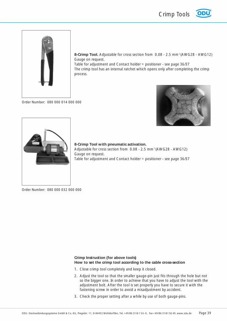
Order Number: 080 000 014 000 000
Order Number: 080 000 032 000 000
8-Crimp Tool. Adjustable for cross section from 0.08 - 2.5 mm 2 (AWG28 - AWG12)Gauge on request.Table for adjustment and Contact holder = positioner - see page 36/37The crimp tool has an internal ratchet which opens only after completing the crimpprocess.
8-Crimp Tool with pneumatic activation.Adjustable for cross section from 0.08 - 2.5 mm 2 (AWG28 - AWG12)Gauge on request.Table for adjustment and Contact holder = positioner - see page 36/37
Crimp Instruction (for above tools)How to set the crimp tool according to the cable cross-section
1. Close crimp tool completely and keep it closed.
2. Adjust the tool so that the smaller gauge-pin just fits through the hole but not so the bigger one. In order to achieve that you have to adjust the tool with the adjustment bolt. After the tool is set properly you have to secure it with the fastening screw in order to avoid a misadjustment by accident.
3. Check the proper setting after a while by use of both gauge-pins.
Crimp Tools
ODU -Steckverbindungssysteme GmbH & Co. KG, Pregelstr. 11, D-84453 Mühldorf/Inn, Tel. +49/86 31/61 56-0, Fax +49/86 31/61 56 49, www.odu.de Page 39
Crimp Tools
Page 40 ODU -Steckverbindungssysteme GmbH & Co. KG, Pregelstr. 11, D-84453 Mühldorf/Inn, Tel. +49/86 31/61 56-0, Fax +49/86 31/61 56 49, www.odu.de
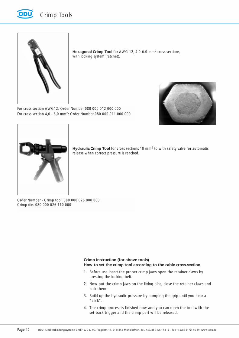
Hexagonal Crimp Tool for AWG 12, 4.0-6.0 mm2 cross sections, with locking system (ratchet).
Hydraulic Crimp Tool for cross sections 10 mm2 to with safety valve for automaticrelease when correct pressure is reached.
Crimp Instruction (for above tools)How to set the crimp tool according to the cable cross-section
1. Before use insert the proper crimp jaws open the retainer claws by pressing the locking belt.
2. Now put the crimp jaws on the fixing pins, close the retainer claws and lock them.
3. Build up the hydraulic pressure by pumping the grip until you hear a “click”.
4. The crimp process is finished now and you can open the tool with the set-back trigger and the crimp part will be released.
For cross section AWG12: Order Number 080 000 012 000 000For cross section 4,0 - 6,0 mm2: Order Number 080 000 011 000 000
Order Number - Crimp tool: 080 000 026 000 000Crimp die: 080 000 026 110 000
Crimp-Tools
ODU -Steckverbindungssysteme GmbH & Co. KG, Pregelstr. 11, D-84453 Mühldorf/Inn, Tel. +49/86 31/61 56-0, Fax +49/86 31/61 56 49, www.odu.de Page 41
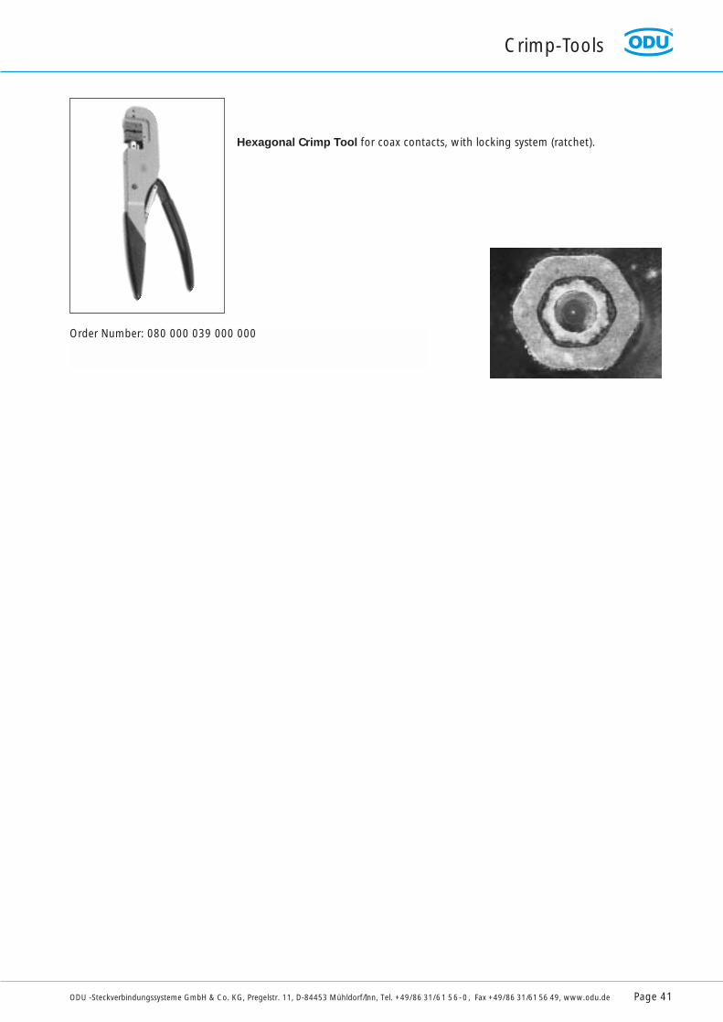
Hexagonal Crimp Tool for coax contacts, with locking system (ratchet).
Order Number: 080 000 039 000 000
Technical Information
Page 42 ODU -Steckverbindungssysteme GmbH & Co. KG, Pregelstr. 11, D-84453 Mühldorf/Inn, Tel. +49/86 31/61 56-0, Fax +49/86 31/61 56 49, www.odu.de
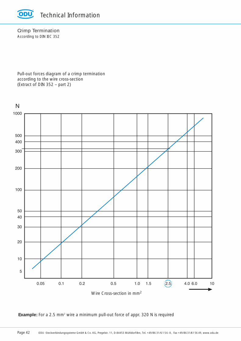
Crimp TerminationAccording to DIN IEC 352
Pull-out forces diagram of a crimp termination according to the wire cross-section(Extract of DIN 352 – part 2)
Example: For a 2.5 mm2 wire a minimum pull-out force of appr. 320 N is required
Wire Cross-section in mm2

Technical Information
ODU -Steckverbindungssysteme GmbH & Co. KG, Pregelstr. 11, D-84453 Mühldorf/Inn, Tel. +49/86 31/61 56-0, Fax +49/86 31/61 56 49, www.odu.de Page 43
Application of VDE 0110-1 for the determination of clearance and creepage distances
The following factors must be determined for clearance and creepage distance dimensioning:
• Value of the nominal line voltage ( generally 230 / 400 V – see Table 1)• Overvoltage Category ( generally Category 3 )• Contamination Level ( generally Level 3 - see Table 2)• Insulation Class ( at ODU, Class IIIa or IIIb - see Table 3 )• Type of field to which the operating materials are subject ( most disadvantageous: inhomogeneous field )
The following text and tables are excerpts from DIN VDE 0110-1 from April 1997 *
Overvoltage categoriesThe fixing of a particular overvoltage category must take place on the basis of the following general description:
– Overvoltage Category I applies to such devices as are intended for connection to the permanent electric installation of a building. Exterior to the device, either in the permanent installation or between the permanent installation and the device, measures are taken for limiting the transient overvoltages to the value in question.
– Overvoltage Category II applies to such devices as are intended for connection to the permanent electric installation of a building. Examples: household appliances, portable tools and similar consumers.
– Overvoltage Category III applies to such devices as are a component of the permanent installation and other devices for which a higher degree of availability is expected. Examples: distribution panels, power switches, distributors in the permanent installation and devices for industrial use .
– Overvoltage Category IV applies to such devices as are intended for the use on or in the vicinity of the feeder in the electric installation of buildings, namely as seen from the main distributor outwards in the direction of the power system. Examples: Electric meters, overvoltage protection switches and ripple control devices.
Three-phase systems
230 /400277 /480400 /690
Nominal voltage of the electric power supplysystem according to IEC 38, in V
Assessment surge voltage, in V
Single-phase systemswith midpoint
120 to 240
Specially protected operating material
Category I800
1500
2500
Operating material forconnection to the
permanent installationCategory II
15002500
4000
Operating material aspart of the permanent
installationCategory III
25004000
6000
Operating material at the installation
feederCategory IV
40006000
8000
Table 1
* Original DIN VDE 0110-1 of April 1997 remains relevant for all omentioned technical information
Technical Information
Page 44 ODU -Steckverbindungssysteme GmbH & Co. KG, Pregelstr. 11, D-84453 Mühldorf/Inn, Tel. +49/86 31/61 56-0, Fax +49/86 31/61 56 49, www.odu.de
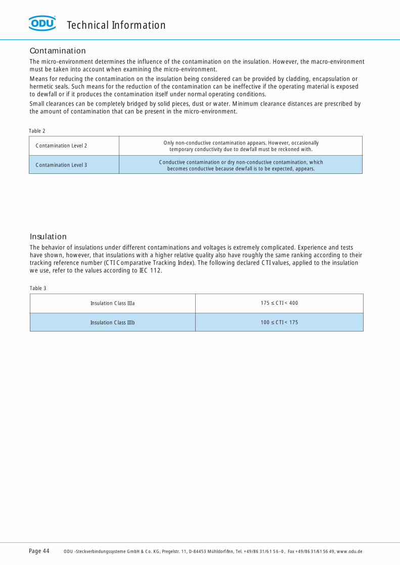
InsulationThe behavior of insulations under different contaminations and voltages is extremely complicated. Experience and testshave shown, however, that insulations with a higher relative quality also have roughly the same ranking according to theirtracking reference number (CTI Comparative Tracking Index). The following declared CTI values, applied to the insulationwe use, refer to the values according to IEC 112.
175 ≤ CTI < 400
100 ≤ CTI < 175
Insulation Class III a
Insulation Class IIIb
ContaminationThe micro-environment determines the influence of the contamination on the insulation. However, the macro-environmentmust be taken into account when examining the micro-environment.
Means for reducing the contamination on the insulation being considered can be provided by cladding, encapsulation orhermetic seals. Such means for the reduction of the contamination can be ineffective if the operating material is exposed to dewfall or if it produces the contamination itself under normal operating conditions.
Small clearances can be completely bridged by solid pieces, dust or water. Minimum clearance distances are prescribed bythe amount of contamination that can be present in the micro-environment.
Only non-conductive contamination appears. However, occasionally temporary conductivity due to dewfall must be reckoned with.
Conductive contamination or dry non-conductive contamination, which becomes conductive because dewfall is to be expected, appears.
Contamination Level 2
Contamination Level 3
Table 2
Table 3

Technical Information
ODU -Steckverbindungssysteme GmbH & Co. KG, Pregelstr. 11, D-84453 Mühldorf/Inn, Tel. +49/86 31/61 56-0, Fax +49/86 31/61 56 49, www.odu.de Page 45
Clearance Distance DimensioningAs laid down in Table 4, clearance distances for base and additional insulation must always be calculated according to the
• assessment surge voltage• impulse withstand voltage
The clearance distances of the reinforced insulation must be selected from Table 4 corresponding to the assessment surgevoltage, however by one level higher in the row of preferred values as compared to the values determined for base insula-tion. If the impulse withstand voltage required for base insulation doesn’t have a value in the row of the preferred values,the reinforced insulation must be dimensioned so that it withstands 160 % of the impulse withstand voltage for baseinsulation.
1) This voltage is • for function insulation: the highest surge voltage to be expected at the clearance;• for base insulation, if directly or substantially influenced by transient overvoltage from the low voltage power system:
the assessment surge voltage of the operating materials;• for other base insulation: the highest surge voltage that can occur in the circuit;• for reinforced insulation.
2) Preferred values3) The minimum clearance distances are based more on experience than on basic knowledge.
Minimum clearance distances in air for installation altitudes up to 2000 m above sea level
Required impulse withstand voltage 1)
Condition A (inhomogeneous Field)Contamination Level
2mm
0.2 3)
0.250.50
3mm
0.8 3)
KV0.33 2)
0.400.50 2)
0.600.80 2)
1.01.21.5 2)
2.02.5 2)
3.04.0 2)
5.0
1.01.52.03.04.0
Table 4
Technical Information
Page 46 ODU -Steckverbindungssysteme GmbH & Co. KG, Pregelstr. 11, D-84453 Mühldorf/Inn, Tel. +49/86 31/61 56-0, Fax +49/86 31/61 56 49, www.odu.de
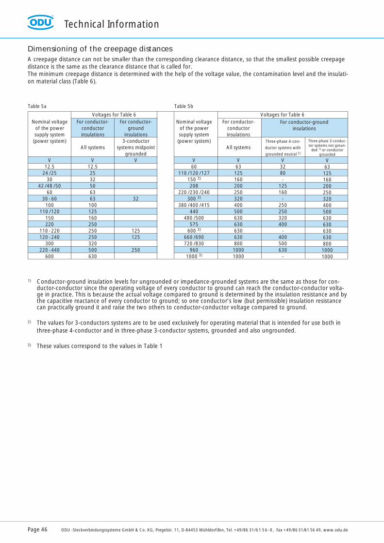
Dimensioning of the creepage distancesA creepage distance can not be smaller than the corresponding clearance distance, so that the smallest possible creepagedistance is the same as the clearance distance that is called for.The minimum creepage distance is determined with the help of the voltage value, the contamination level and the insulati-on material class (Table 6).
1) Conductor-ground insulation levels for ungrounded or impedance-grounded systems are the same as those for con-ductor-conductor since the operating voltage of every conductor to ground can reach the conductor-conductor volta-ge in practice. This is because the actual voltage compared to ground is determined by the insulation resistance and by the capacitive reactance of every conductor to ground; so one conductor’s low (but permissible) insulation resistance can practically ground it and raise the two others to conductor-conductor voltage compared to ground.
2) The values for 3-conductors systems are to be used exclusively for operating material that is intended for use both in three-phase 4-conductor and in three-phase 3-conductor systems, grounded and also ungrounded.
3) These values correspond to the values in Table 1
Nominal voltageof the powersupply system(power system)
V12.5
24 /2530
42 /48 /5060
30 - 60100
110 /120150220
110 -220120 -240
300220 -440
600
For conductor-conductor insulations
All systems
V12.52532506363100125160250250250320500630
For conductor-ground
insulations3-conductor
systems midpointgrounded
V
32
125125
250
Nominal voltageof the power supply system (power system)
V60
110 /120 /127150 3)
208220 /230 /240
300 3)
380 /400 /415440
480 /500575
600 3)
660 /690720 /830
9601000 3)
For conductor-conductor insulations
All systems
V6312516020025032040050063063063063080010001000
Three-phase 4-con-
ductor systems with
grounded neutral 2)
V3280-
125160
-250250320400
-400500630
-
Three-phase 3-conduc-tor systems not groun-
ded 1) or conductorgrounded
V6312516020025032040050063063063063080010001000
Voltages for Table 6 Voltages for Table 6For conductor-ground
insulations
Table 5a Table 5b
Technical Information
ODU -Steckverbindungssysteme GmbH & Co. KG, Pregelstr. 11, D-84453 Mühldorf/Inn, Tel. +49/86 31/61 56-0, Fax +49/86 31/61 56 49, www.odu.de Page 47
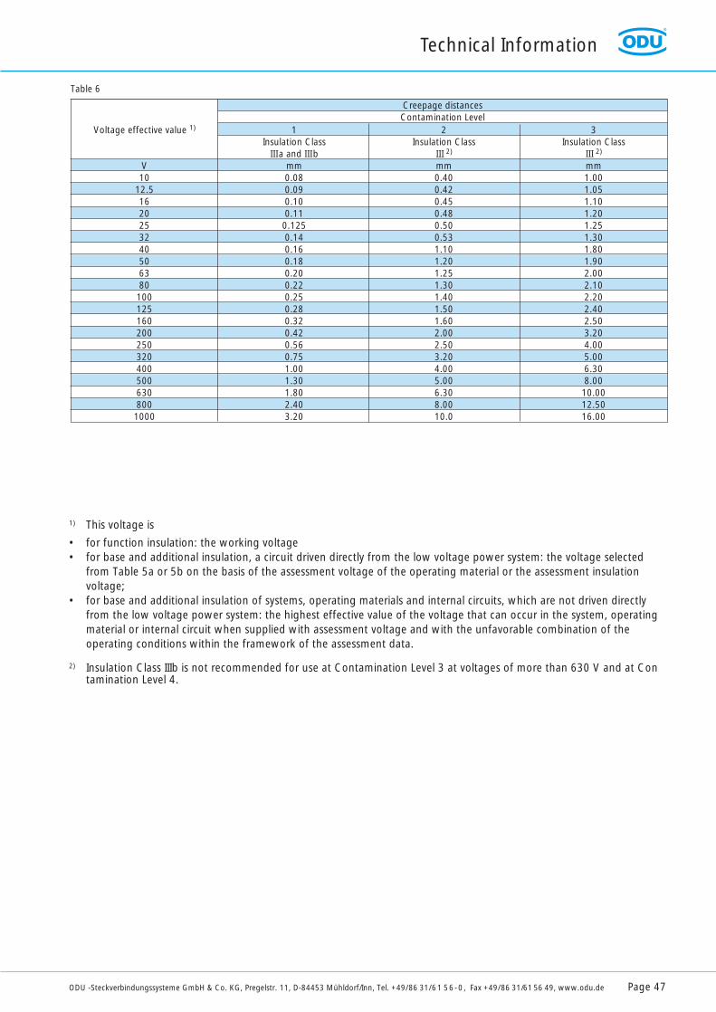
1) This voltage is
• for function insulation: the working voltage• for base and additional insulation, a circuit driven directly from the low voltage power system: the voltage selected
from Table 5a or 5b on the basis of the assessment voltage of the operating material or the assessment insulation voltage;
• for base and additional insulation of systems, operating materials and internal circuits, which are not driven directly from the low voltage power system: the highest effective value of the voltage that can occur in the system, operating material or internal circuit when supplied with assessment voltage and with the unfavorable combination of the operating conditions within the framework of the assessment data.
2) Insulation Class IIIb is not recommended for use at Contamination Level 3 at voltages of more than 630 V and at Contamination Level 4.
Voltage effective value 1)
V10
12.516202532405063801001251602002503204005006308001000
1Insulation Class
IIIa and IIIbmm0.080.090.100.110.1250.140.160.180.200.220.250.280.320.420.560.751.001.301.802.403.20
2Insulation Class
III 2)
mm0.400.420.450.480.500.531.101.201.251.301.401.501.602.002.503.204.005.006.308.0010.0
3Insulation Class
III 2)
mm1.001.051.101.201.251.301.801.902.002.102.202.402.503.204.005.006.308.0010.0012.5016.00
Creepage distancesContamination Level
Table 6
ODU-MAC
Page 48 ODU -Steckverbindungssysteme GmbH & Co. KG, Pregelstr. 11, D-84453 Mühldorf/Inn, Tel. +49/86 31/61 56-0, Fax +49/86 31/61 56 49, www.odu.de
ODU-MAC Application Example
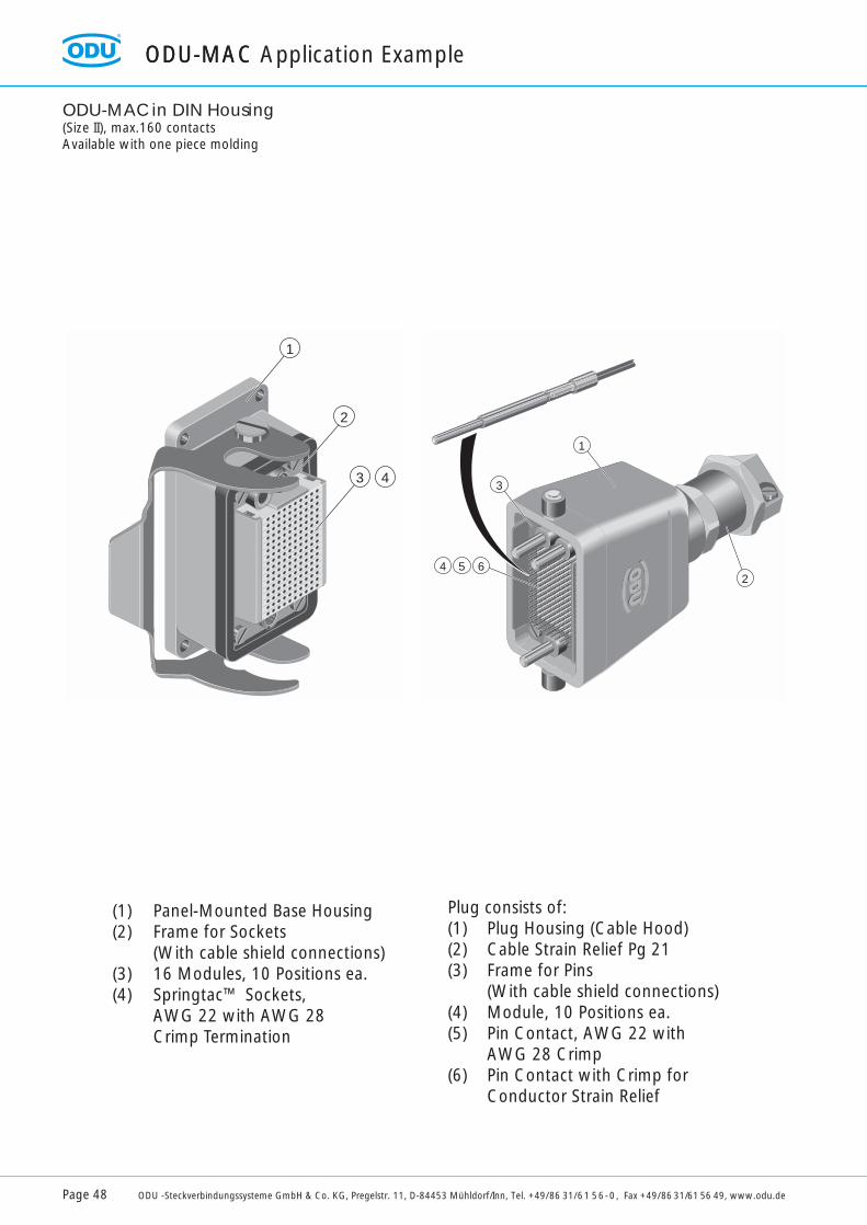
ODU-MAC in DIN Housing(Size II), max.160 contactsAvailable with one piece molding
654
3
1
2
R R
1
2
3 4
Plug consists of:(1) Plug Housing (Cable Hood)(2) Cable Strain Relief Pg 21(3) Frame for Pins
(With cable shield connections)(4) Module, 10 Positions ea.(5) Pin Contact, AWG 22 with
AWG 28 Crimp(6) Pin Contact with Crimp for
Conductor Strain Relief
(1) Panel-Mounted Base Housing(2) Frame for Sockets
(With cable shield connections)(3) 16 Modules, 10 Positions ea.(4) Springtac™ Sockets,
AWG 22 with AWG 28 Crimp Termination

ODU-MAC in DIN HousingWith locking lever for simple, one-handed operations.Accepts maximum 680 contacts.
7090
ca. 180
148
165
132
40 96
Shown is Plug (Example)
1 2 3 4 5 6 7 8 9 10 11 12 13 14 15 16 17 18 19 20 21
AB
CD
EF
GH
JK
22 23 24 25 26 27 28 29 30 31 32 33 34
1 2 3 4 5 6 7 8 9 10 11 12 13 14 15 16 17 18 19 20 21
AB
CD
EF
GH
JK
22 23 24 25 26 27 28 29 30 31 32 33 34
ODU-MAC Application Example
ODU -Steckverbindungssysteme GmbH & Co. KG, Pregelstr. 11, D-84453 Mühldorf/Inn, Tel. +49/86 31/61 56-0, Fax +49/86 31/61 56 49, www.odu.de Page 49
ODU-MAC Application Example
Page 50 ODU -Steckverbindungssysteme GmbH & Co. KG, Pregelstr. 11, D-84453 Mühldorf/Inn, Tel. +49/86 31/61 56-0, Fax +49/86 31/61 56 49, www.odu.de
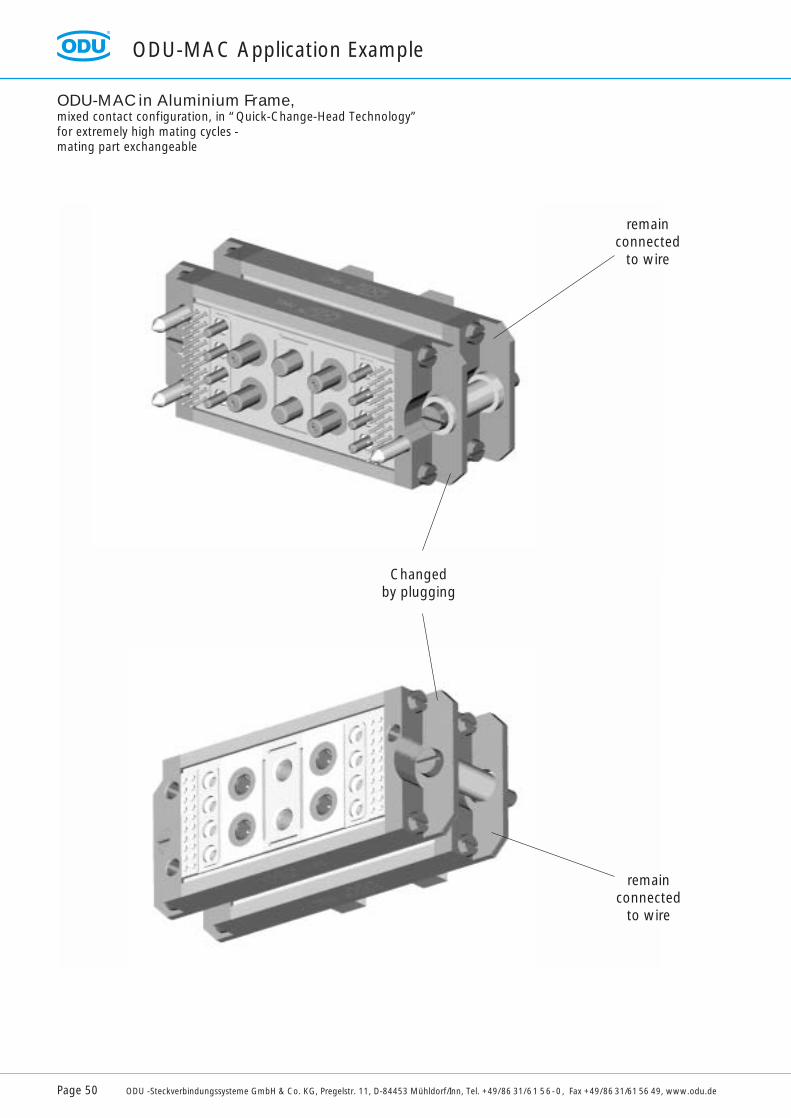
ODU-MAC in Aluminium Frame,mixed contact configuration, in “Quick-Change-Head Technology”for extremely high mating cycles -mating part exchangeable
remainconnected
to wire
remainconnected
to wire
Changedby plugging
Connection during the testing of mass-produced electronic articles
Car radios, video recorders, mobile telephones, fuel injection pumps, motor controllers, printers, printed circuit boards, video screens, frequency converters, microwave ovens, ABS systems, automobile motors, electric scales:all of these products are produced in large-scale manufacturing and must be tested.This requires that the products (test pieces) be connected and attached to a test computer. The test requires:
1. connection to the product and,2. in most cases, an interface (a connector) between the test piece and the computer.
ODU has developed special products that are being used worldwide for both tasks.
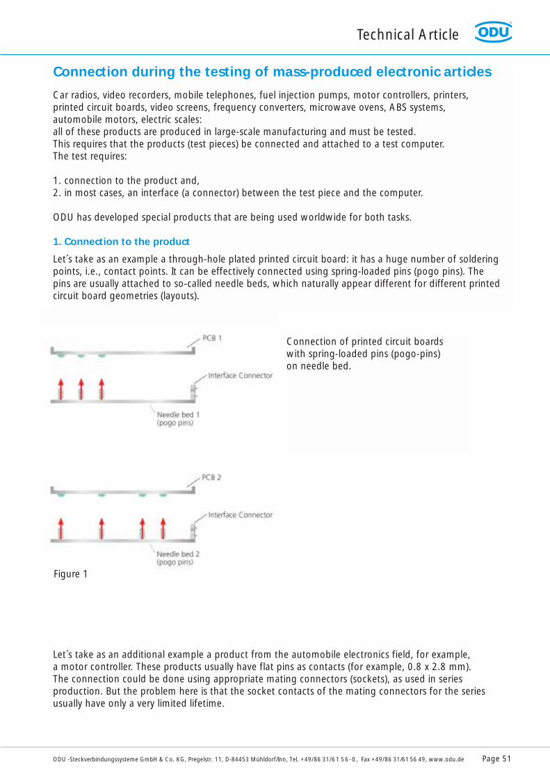
1. Connection to the product
Let´s take as an example a through-hole plated printed circuit board: it has a huge number of solderingpoints, i.e., contact points. It can be effectively connected using spring-loaded pins (pogo pins). The pins are usually attached to so-called needle beds, which naturally appear different for different printedcircuit board geometries (layouts).
Let´s take as an additional example a product from the automobile electronics field, for example, a motor controller. These products usually have flat pins as contacts (for example, 0.8 x 2.8 mm). The connection could be done using appropriate mating connectors (sockets), as used in series production. But the problem here is that the socket contacts of the mating connectors for the seriesusually have only a very limited lifetime.
Technical Article
ODU -Steckverbindungssysteme GmbH & Co. KG, Pregelstr. 11, D-84453 Mühldorf/Inn, Tel. +49/86 31/61 56-0, Fax +49/86 31/61 56 49, www.odu.de Page 51
Connection of printed circuit boardswith spring-loaded pins (pogo-pins)on needle bed.
Figure 1
Technical Article
Page 52 ODU -Steckverbindungssysteme GmbH & Co. KG, Pregelstr. 11, D-84453 Mühldorf/Inn, Tel. +49/86 31/61 56-0, Fax +49/86 31/61 56 49, www.odu.de
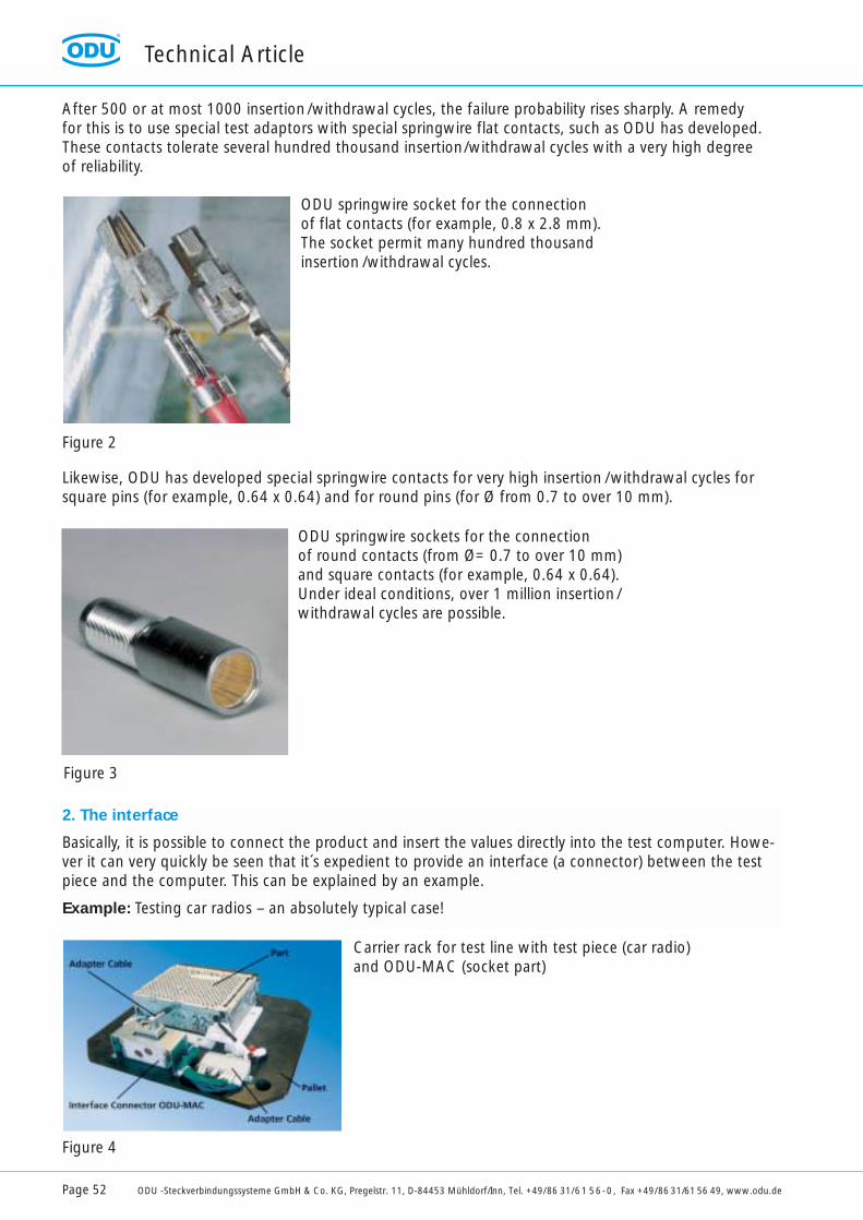
After 500 or at most 1000 insertion/withdrawal cycles, the failure probability rises sharply. A remedy for this is to use special test adaptors with special springwire flat contacts, such as ODU has developed.These contacts tolerate several hundred thousand insertion/withdrawal cycles with a very high degree of reliability.
Likewise, ODU has developed special springwire contacts for very high insertion /withdrawal cycles forsquare pins (for example, 0.64 x 0.64) and for round pins (for Ø from 0.7 to over 10 mm).
ODU springwire socket for the connection of flat contacts (for example, 0.8 x 2.8 mm).The socket permit many hundred thousandinsertion /withdrawal cycles.
ODU springwire sockets for the connection of round contacts (from Ø= 0.7 to over 10 mm)and square contacts (for example, 0.64 x 0.64). Under ideal conditions, over 1 million insertion/withdrawal cycles are possible.
Carrier rack for test line with test piece (car radio)and ODU-MAC (socket part)
2. The interface
Basically, it is possible to connect the product and insert the values directly into the test computer. Howe-ver it can very quickly be seen that it´s expedient to provide an interface (a connector) between the testpiece and the computer. This can be explained by an example.
Example: Testing car radios – an absolutely typical case!
Figure 2
Figure 3
Figure 4
Technical Article
ODU -Steckverbindungssysteme GmbH & Co. KG, Pregelstr. 11, D-84453 Mühldorf/Inn, Tel. +49/86 31/61 56-0, Fax +49/86 31/61 56 49, www.odu.de Page 53
In Figure 4 one sees a carrier rack with an interface connector (ODU-MAC) permanently mounted on it,a car radio and 2 adaptor cables, which produce the connection from the car radio to the ODU-MAC.The adaptor cables are permanently connected to the ODU-MAC while on the side of the car radio theyare freshly inserted for every test piece. The interface connector (ODU-MAC) is then docked within theframework of the test step in the test line so that the signals can be transmitted over the matingconnector to the computer side and can then be processed in the computer.
In this case the adapter connenctors are worked with every tested radio. Especially high demands are placed on the ODU-MAC: the connector on the computer side is worked at least 10,000 times for 10,000 radios per day, and proportionately more in the case of multiple tests. This means at leastapproximately 3 million insertion/withdrawal cycles a year! In addition, in this case the ODU-MAC must be equipped with power contacts, signal contacts and high frequency (HF) contacts with 75 Ωcharacteristic impedance.
Here one can – rightfully – ask the question: why provide an expensive interface connector when the adaptor cable connector still has to be plugged in – usually manually – anyway?
There are different, mutually independent reasons for this:
- Program changeMultiple test on the same test piece (Figure 5)Without interface connectors, the adaptor cables would have to be repeatedly plugged by hand, which would mean multiple time required and also that the adaptor connector would wear out earlier.The high number of insertion/withdrawal cycles is shifted to the ODU-MAC, which is suitable for this.
- Better utilization of the expensive test computersThe attachment of the adaptor cable is often truly time-consuming since several different connectors must be multiply plugged – mostly by hand. So it is expedient to plug the adaptor cable to the racks in a decentralized manner at a great distance from the test computer and then to run the racks quicklythrough the test line.
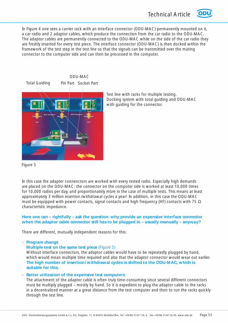
Test line with racks for multiple testing. Docking system with total guiding and ODU-MAC with guiding for the connector.
Total Guiding
ODU-MAC
Pin Part Socket Part
Figure 5
Technical Article
Page 54 ODU -Steckverbindungssysteme GmbH & Co. KG, Pregelstr. 11, D-84453 Mühldorf/Inn, Tel. +49/86 31/61 56-0, Fax +49/86 31/61 56 49, www.odu.de
- Buffer stockThis reason is closely related to the one above. With decentralized preperation, the adaptor cables can be plugged in the 2nd and 3rd shift, for example, while the test line and test computer run only during the main shift under the presence of the permanent staff.
In the following, the use of interface connectors in the case of program changes and for additional exam-ples is explained.
Program change
Example: Testing printed circuit boards
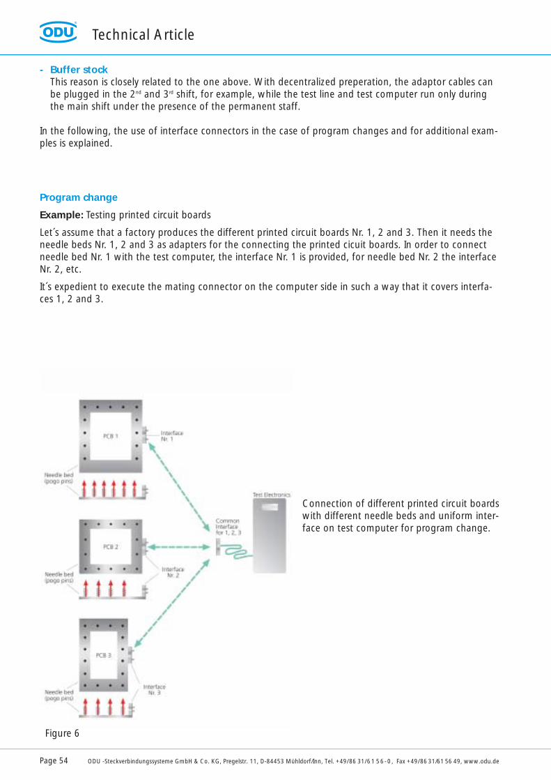
Let´s assume that a factory produces the different printed circuit boards Nr. 1, 2 and 3. Then it needs theneedle beds Nr. 1, 2 and 3 as adapters for the connecting the printed cicuit boards. In order to connectneedle bed Nr. 1 with the test computer, the interface Nr. 1 is provided, for needle bed Nr. 2 the interfaceNr. 2, etc.
It´s expedient to execute the mating connector on the computer side in such a way that it covers interfa-ces 1, 2 and 3.
Connection of different printed circuit boardswith different needle beds and uniform inter-face on test computer for program change.
Figure 6
Technical Article
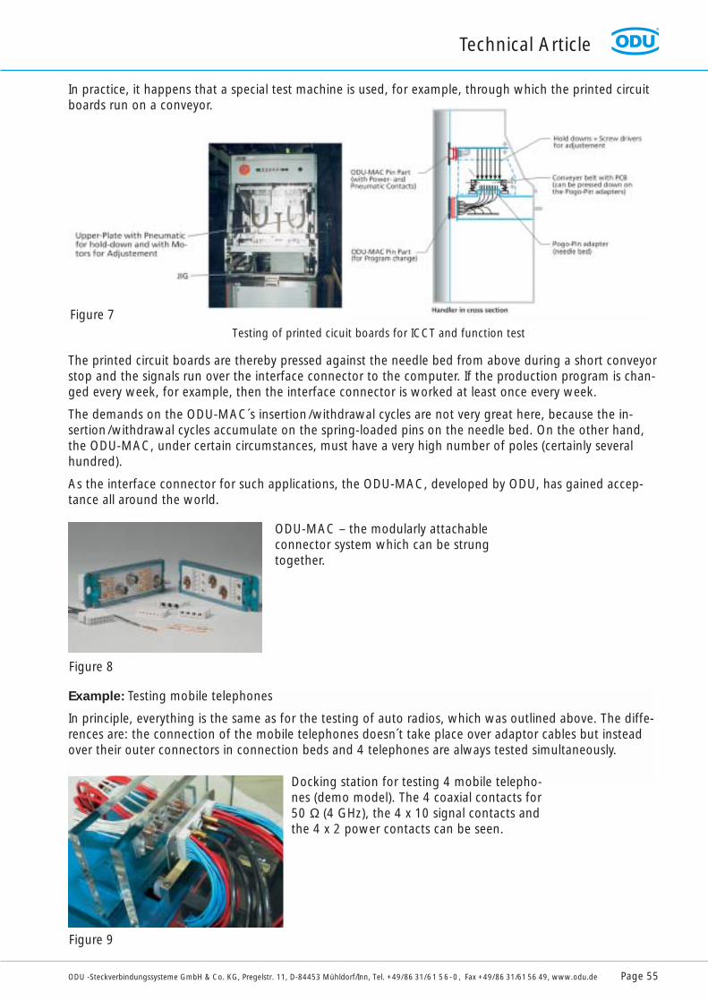
ODU -Steckverbindungssysteme GmbH & Co. KG, Pregelstr. 11, D-84453 Mühldorf/Inn, Tel. +49/86 31/61 56-0, Fax +49/86 31/61 56 49, www.odu.de Page 55
The printed circuit boards are thereby pressed against the needle bed from above during a short conveyorstop and the signals run over the interface connector to the computer. If the production program is chan-ged every week, for example, then the interface connector is worked at least once every week.
The demands on the ODU-MAC´s insertion/withdrawal cycles are not very great here, because the in-sertion/withdrawal cycles accumulate on the spring-loaded pins on the needle bed. On the other hand,the ODU-MAC, under certain circumstances, must have a very high number of poles (certainly severalhundred).
As the interface connector for such applications, the ODU-MAC, developed by ODU, has gained accep-tance all around the world.
Example: Testing mobile telephones
In principle, everything is the same as for the testing of auto radios, which was outlined above. The diffe-rences are: the connection of the mobile telephones doesn´t take place over adaptor cables but insteadover their outer connectors in connection beds and 4 telephones are always tested simultaneously.
In practice, it happens that a special test machine is used, for example, through which the printed circuitboards run on a conveyor.
ODU-MAC – the modularly attachableconnector system which can be strungtogether.
Docking station for testing 4 mobile telepho-nes (demo model). The 4 coaxial contacts for50 Ω (4 GHz), the 4 x 10 signal contacts andthe 4 x 2 power contacts can be seen.
Testing of printed cicuit boards for ICCT and function test
Figure 7
Figure 9
Figure 8
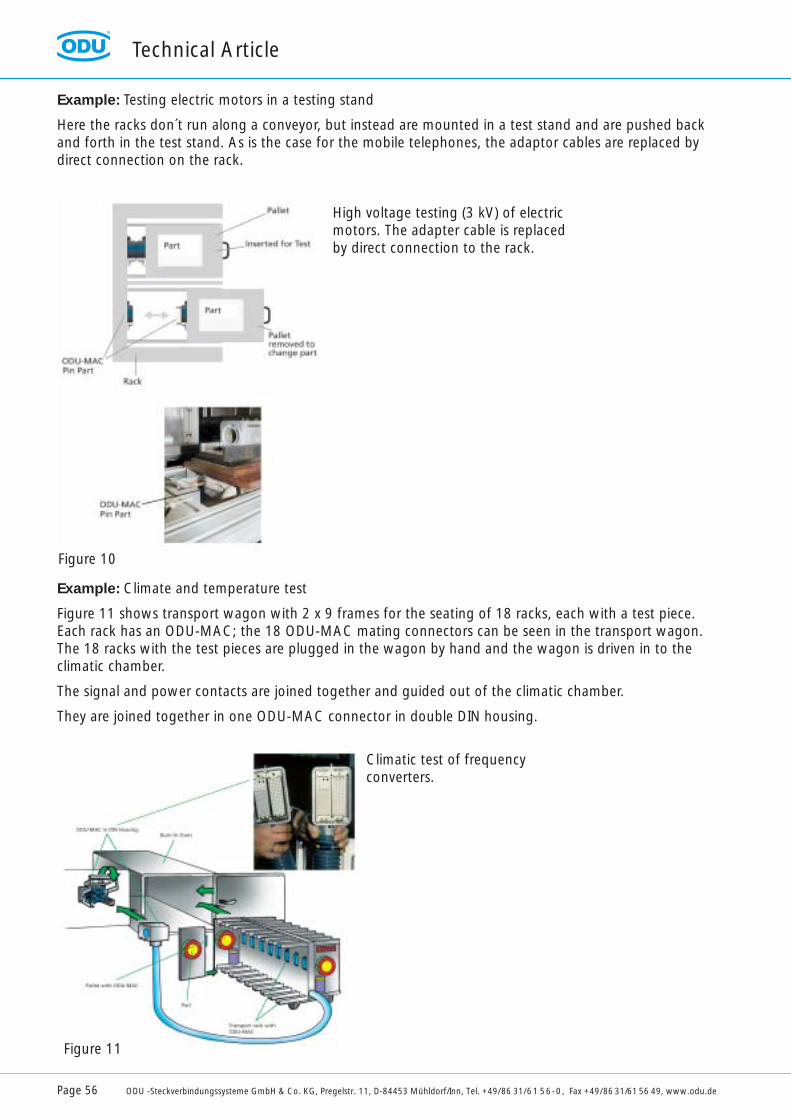
Technical Article
Page 56 ODU -Steckverbindungssysteme GmbH & Co. KG, Pregelstr. 11, D-84453 Mühldorf/Inn, Tel. +49/86 31/61 56-0, Fax +49/86 31/61 56 49, www.odu.de
Example: Testing electric motors in a testing stand
Here the racks don´t run along a conveyor, but instead are mounted in a test stand and are pushed backand forth in the test stand. As is the case for the mobile telephones, the adaptor cables are replaced bydirect connection on the rack.
Example: Climate and temperature test
Figure 11 shows transport wagon with 2 x 9 frames for the seating of 18 racks, each with a test piece.Each rack has an ODU-MAC; the 18 ODU-MAC mating connectors can be seen in the transport wagon.The 18 racks with the test pieces are plugged in the wagon by hand and the wagon is driven in to the climatic chamber.
The signal and power contacts are joined together and guided out of the climatic chamber.
They are joined together in one ODU-MAC connector in double DIN housing.
High voltage testing (3 kV) of electricmotors. The adapter cable is replacedby direct connection to the rack.
Climatic test of frequency converters.
Figure 10
Figure 11
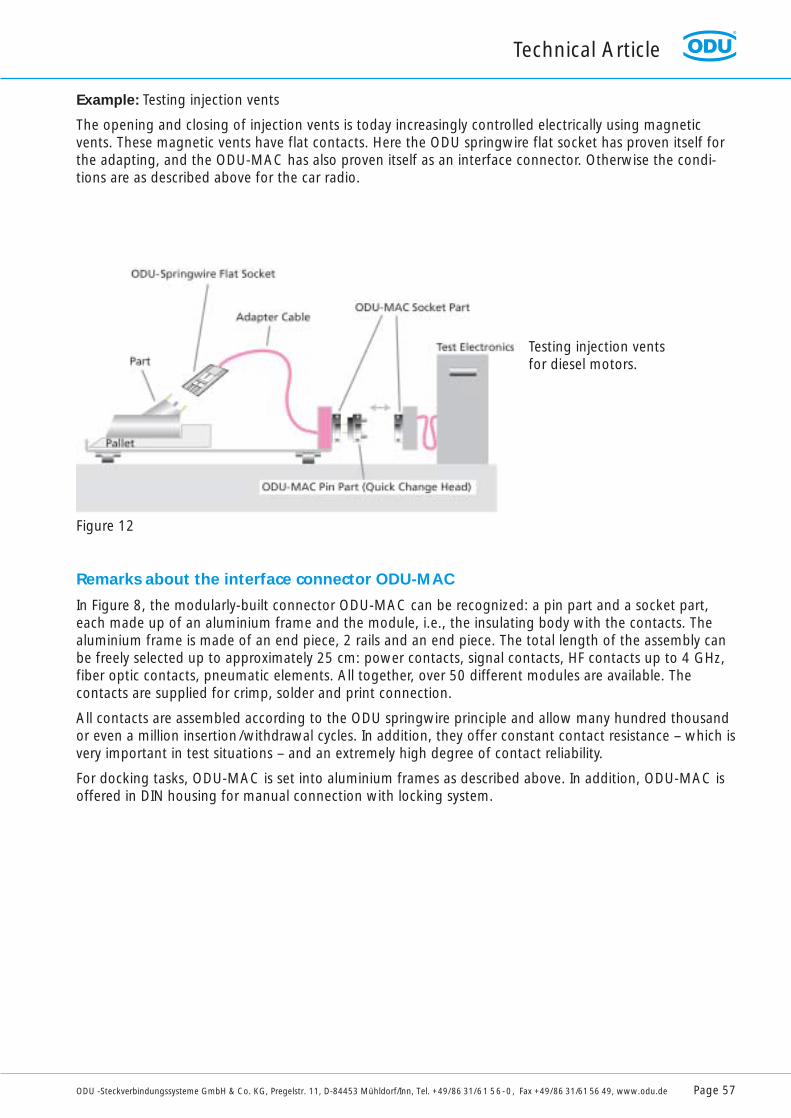
Technical Article
ODU -Steckverbindungssysteme GmbH & Co. KG, Pregelstr. 11, D-84453 Mühldorf/Inn, Tel. +49/86 31/61 56-0, Fax +49/86 31/61 56 49, www.odu.de Page 57
Example: Testing injection vents
The opening and closing of injection vents is today increasingly controlled electrically using magneticvents. These magnetic vents have flat contacts. Here the ODU springwire flat socket has proven itself forthe adapting, and the ODU-MAC has also proven itself as an interface connector. Otherwise the condi-tions are as described above for the car radio.
Remarks about the interface connector ODU-MAC
In Figure 8, the modularly-built connector ODU-MAC can be recognized: a pin part and a socket part,each made up of an aluminium frame and the module, i.e., the insulating body with the contacts. Thealuminium frame is made of an end piece, 2 rails and an end piece. The total length of the assembly canbe freely selected up to approximately 25 cm: power contacts, signal contacts, HF contacts up to 4 GHz,fiber optic contacts, pneumatic elements. All together, over 50 different modules are available. Thecontacts are supplied for crimp, solder and print connection.
All contacts are assembled according to the ODU springwire principle and allow many hundred thousandor even a million insertion/withdrawal cycles. In addition, they offer constant contact resistance – which isvery important in test situations – and an extremely high degree of contact reliability.
For docking tasks, ODU-MAC is set into aluminium frames as described above. In addition, ODU-MAC isoffered in DIN housing for manual connection with locking system.
Testing injection vents for diesel motors.
Figure 12
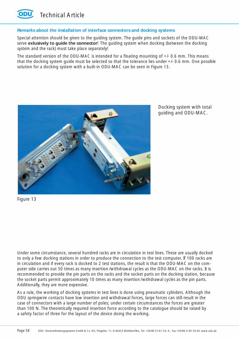
Technical Article
Page 58 ODU -Steckverbindungssysteme GmbH & Co. KG, Pregelstr. 11, D-84453 Mühldorf/Inn, Tel. +49/86 31/61 56-0, Fax +49/86 31/61 56 49, www.odu.de
Remarks about the installation of interface connectors and docking systems
Special attention should be given to the guiding system. The guide pins and sockets of the ODU-MACserve exlusively to guide the connector! The guiding system when docking (between the dockingsystem and the rack) must take place separately!
The standard version of the ODU-MAC is intended for a floating mounting of +/- 0.6 mm. This meansthat the docking system guide must be selected so that the tolerance lies under +/- 0.6 mm. One possiblesolution for a docking system with a built-in ODU-MAC can be seen in Figure 13.
Under some circumstance, several hundred racks are in circulation in test lines. These are usually dockedto only a few docking stations in order to produce the connection to the test computer. If 100 racks arein circulation and if every rack is docked to 2 test stations, the result is that the ODU-MAC on the com-puter side carries out 50 times as many insertion /withdrawal cycles as the ODU-MAC on the racks. It isrecommended to provide the pin parts on the racks and the socket parts on the docking station, becausethe socket parts permit approximately 10 times as many insertion/withdrawal cycles as the pin parts.Additionally, they are more expensive.
As a rule, the working of docking systems in test lines is done using pneumatic cylinders. Although theODU springwire contacts have low insertion and withdrawal forces, large forces can still result in the case of connectors with a large number of poles; under certain circumstances the forces are greater than 100 N. The theoretically required insertion force according to the catalogue should be raised by a safety factor of three for the layout of the device doing the working.
Docking system with total guiding and ODU-MAC.
Figure 13
Technical Article
ODU -Steckverbindungssysteme GmbH & Co. KG, Pregelstr. 11, D-84453 Mühldorf/Inn, Tel. +49/86 31/61 56-0, Fax +49/86 31/61 56 49, www.odu.de Page 59
Some remarks about the profitability. References.
Test equipment is expensive. The costs must be seen in connection with the use. In no case shouldcosts be saved on the connection!In addition to the costs for the test computers, the test equipment /line and the docking system must betaken into consideration. In addition to the costs for the adaptation, costs for the interface connectorODU-MAC arise as well as, under some circumstances, considerable costs for their mass production.On the other hand it needs to be taken into consideration that not only insufficiently tested products can lead to failure and dissatisfaction. In addition, bad test equipment leads time and time again to errormessages, especially due to bad connection.Under some circumstances, flawless products are rejected. This can lead to entire factories being broughtto a standstill.
Some of the customers who have chosen the adaptor contact from ODU and the ODU-MAC are: Alcatel,Bosch, Daimler-Chrysler, Ericsson, Matsushita, Mitsubishi, Nokia, Oki, Philips, Samsung, Siemens, Sony,Wabco.Approximately 100 million mobile telephones alone are currently being tested with ODU-MAC everyyear!
In addition to testing situations, ODU-MAC is being used in machine construction (pick and place machi-nes, automatic assembly machines) and in medical technology, among other applications.Documentation is available in German, English, French, Japanese and Korean.

ODU’s headquarters and factory are located in Mühldorf, at the river Inn,approximately 50 miles east of Munich, at the foothills of the Bavarian Alps.
Mühldorf, an idyllic small town with its typical Inn-Salzach architecture.Ph
oto
of C
ity M
ühld
orf/
Inn
Werr
.09
/01
SteckverbindungssystemeODU-Steckverbindungssysteme GmbH & Co. KGOtto Dunkel GmbH
Pregelstraße 11 · D-84453 Mühldorf/InnTelefon +49/86 31/61 56-0Fax +49/86 31/61 56 49Internet: http://www.odu.deE-Mail: [email protected]
ODU FranceTéléphone: 01.39.35.46.90Télécopie: 01.39.35.46.91E-Mail: [email protected]
ODU-UK Ltd.Tel. 01509 266 433Fax 01509 266 777E-Mail: [email protected]
ODU Scandinavia ABTel. +46/176-1 82 61Fax +46/176-1 82 62E-Mail: [email protected]
ODU USA Inc.Tel. 805.484.0540Fax 805.484.7458E-Mail: [email protected]://www.odu-usa.com
ODU-ShanghaiTel. 00 86/2162/34 29 86Fax 00 86/2162/34 29 86E-Mail: [email protected]