Embed Size (px)
Citation preview

M9TU Product Manual USB 3.0 - 2.5” Hard Disk Drive
September 05, 2013 Rev 1.0 PMM9T-USB3.0 100736109a

© 2013 Seagate Technology LLC. All rights reserved. Seagate and Seagate Technology are registered trademarks of Seagate Technology LLC in the United States and/or other countries. Momentus is either a trademark or registered trademark of Seagate Technology LLC or one of its affiliated companies in the United States and/or other countries. All other trademarks or registered trademarks are the property of their respective owners. When referring to drive capacity, one gigabyte, or GB, equals one billion bytes and one terabyte, or TB, equals one trillion bytes. Your computer’s operating system may use a different standard of measurement and report a lower capacity. In addition, some of the listed capacity is used for formatting and other functions, and thus will not be available for data storage. Actual data rates may vary depending on operating environment and other factors. The export or re-export of hardware or software containing encryption may be regulated by the U.S. Department of Commerce, Bureau of Industry and Security (for more information, visit www.bis.doc.gov), and controlled for import and use outside of the U.S. Seagate reserves the right to change, without notice, product offerings or specifications.
TABLE OF CONTENTS
CHAPTER 1 SCOPE ............................................................................................................................. 1
1.1 USER DEFINITION .............................................................................................................................. 1 1.2 MANUAL ORGANIZATION .................................................................................................................. 1 1.3 USB .................................................................................................................................................... 1 1.4 REFERENCE ........................................................................................................................................ 2
CHAPTER 2 DESCRIPTION ............................................................................................................. 3
2.1 INTRODUCTION .................................................................................................................................. 3 2.2 KEY FEATURES .................................................................................................................................. 3 2.3 STANDARDS AND REGULATIONS....................................................................................................... 4 2.4 HARDWARE REQUIREMENTS............................................................................................................. 4
CHAPTER 3 SPECIFICATIONS ....................................................................................................... 5
3.1 SPECIFICATION SUMMARY ................................................................................................................ 5 3.2 PHYSICAL SPECIFICATIONS ............................................................................................................... 5 3.3 LOGICAL CONFIGURATIONS.............................................................................................................. 5 3.4 PERFORMANCE SPECIFICATIONS ..................................................................................................... 6 3.5 POWER CONSUMPTION ..................................................................................................................... 7 3.6 ENVIRONMENTAL SPECIFICATIONS ............................................................................................... 8 3.7 RELIABILITY SPECIFICATIONS ....................................................................................................... 9
CHAPTER 4 INSTALLATION......................................................................................................... 10
4.1 SPACE REQUIREMENTS................................................................................................................... 10 4.2 UNPACKING INSTRUCTIONS............................................................................................................ 10 4.3 MOUNTING ...................................................................................................................................... 10
4.3.1 Orientation...................................................................................................................... 11 4.3.2 Ventilation ...................................................................................................................... 11
4.4 CABLE CONNECTORS....................................................................................................................... 12 4.4.1 USB Connectivity............................................................................................................ 12
4.5 DRIVE INSTALLATION...................................................................................................................... 12 4.6 SYSTEM STARTUP PROCEDURE ....................................................................................................... 13
CHAPTER 5 DISK DRIVE OPERATION........................................................................................ 14
5.1 HEAD / DISK ASSEMBLY (HDA) ...................................................................................................... 14 5.1.1 Base Casting Assembly ................................................................................................... 14 5.1.2 DC Spindle Motor Assembly ........................................................................................... 14 5.1.3 Disk Stack Assembly ....................................................................................................... 14 5.1.4 Head Stack Assembly ...................................................................................................... 14 5.1.5 Voice Coil Motor and Actuator Latch Assemblies ......................................................... 15 5.1.6 Air Filtration System....................................................................................................... 15 5.1.7 Load/Unload Mechanism................................................................................................ 16
5.2 DRIVE ELECTRONICS ....................................................................................................................... 16 5.2.1 Digital Signal Process and Interface Controller ............................................................ 16 5.2.2 USB Interface Controller................................................................................................ 16
5.2.2.1 The Host Interface Control Block ................................................................................................. 16 5.2.2.2 The Buffer Control Block ............................................................................................................. 17 5.2.2.3 The Disk Control Block ................................................................................................................ 17 5.2.2.4 The Disk ECC Control Block........................................................................................................ 17 5.2.2.5 Power Management....................................................................................................................... 17
5.2.3 Read/Write IC ................................................................................................................. 18 5.2.3.1 Time Base Generator.......................................................................................................................... 18 5.2.3.2 Automatic Gain Control ..................................................................................................................... 18 5.2.3.3 Asymmetry Correction Circuitry (ASC) ............................................................................................ 18 5.2.3.4 Analog Anti-Aliasing Low Pass Filter ................................................................................................ 18 5.2.3.5 Analog to Digital Converter (ADC) and FIR ...................................................................................... 18
5.3 SERVO SYSTEM ................................................................................................................................ 20 5.4 READ AND WRITE OPERATIONS ...................................................................................................... 20
5.4.1 The Read Channel........................................................................................................... 20 5.4.2 The Write Channel .......................................................................................................... 20
5.5 FIRMWARE FEATURES ..................................................................................................................... 21 5.5.1 Read Caching ................................................................................................................. 21 5.5.2 Write Caching ................................................................................................................. 22 5.5.3 Defect Management ........................................................................................................ 22 5.5.4 Automatic Defect Allocation ........................................................................................... 22 5.5.5 Multi Parities Error Correction ..................................................................................... 22
CHAPTER 6 USB INTERFACE AND USB COMMANDS ............................................................ 23
6.1 INTRODUCTION ................................................................................................................................ 23 6.2 PHYSICAL INTERFACE ..................................................................................................................... 23
6.2.1 Mechanical Interface ...................................................................................................... 23 6.2.1.1 Mechanical Overview ................................................................................................................... 23 6.2.1.2 Connector ...................................................................................................................................... 24
6.2.1.2.1 USB Connector Termination Data................................................................................................................... 24 6.2.1.2.2 Series “A” and Series “B” Receptacles ........................................................................................................ 25 6.2.1.2.3 Series “A” and Series “B” Plugs ................................................................................................................... 26
6.2.1.3 Cable................................................................................................................................................. 27 6.2.1.4 Cable Assembly.................................................................................................................................. 27
6.2.1.4.1 Standard Detachable Cable Assemblies .................................................................................................... 27 6.2.1.4.2 High-/full-speed Captive Cable Assemblies............................................................................................... 30 6.2.1.4.3 Low-speed Captive Cable Assemblies ........................................................................................................ 31 6.2.1.4.4 Prohibited Cable Assemblies ...................................................................................................................... 31
6.2.2 Electrical Interface .......................................................................................................... 32 6.2.2.1 Electrical Overview ............................................................................................................................ 32 6.2.2.2 Signaling ............................................................................................................................................ 33 6.2.2.3 High-speed (480Mb/s) Driver Characteristics ................................................................................... 34 6.2.2.4 High-speed (480Mb/s) Signaling Rise and Fall Times ...................................................................... 35 6.2.2.5 High-speed (480Mb/s) Receiver Characteristics ............................................................................... 35 6.2.2.6 High-speed (480Mb/s) Signaling Levels ........................................................................................... 36
6.2.3 Power Distribution ......................................................................................................... 37 6.2.3.1 Overview .............................................................................................................................................. 37 6.2.3.2 Bus-powered Hubs ............................................................................................................................... 37 6.2.3.3 Self-powered Hubs .............................................................................................................................. 38
6.3 PROTOCOL LAYER ............................................................................................................................ 39 6.3.1 Protocol Layer Overview................................................................................................ 39 6.3.2 Common USB Packet Fields ........................................................................................... 40
6.3.2.1 SYNC Fields...................................................................................................................................... 40 6.3.2.2 Packet Identifier Fields...................................................................................................................... 40 6.3.2.3 Address Fields .................................................................................................................................. 41 6.3.2.4 Endpoint Fields.................................................................................................................................. 42 6.3.2.5 Frame Number Fields ....................................................................................................................... 42 6.3.2.6 Data Fields ........................................................................................................................................ 42 6.3.2.7 Cyclic Redundancy Checks .............................................................................................................. 42
6.3.3 Packet Format ................................................................................................................. 43 6.3.3.1 Token Packet..................................................................................................................................... 43 6.3.3.2 Data Packet ....................................................................................................................................... 43 6.3.3.3 Handshake Packet ............................................................................................................................. 43 6.3.3.4 Start-of-Frame Packets...................................................................................................................... 44
6.3.4 Pipes ................................................................................................................................ 44 6.3.5 Transfer/Endpoint Types ................................................................................................. 45
6.3.5.1 Control Transaction........................................................................................................................... 46 6.3.5.2 Bulk Transaction................................................................................................................................ 48
6.3.6 USB Device Generic Framework .................................................................................... 50 6.3.6.1 USB Device State ............................................................................................................................. 50
6.3.6.1.1 Attached .................................................................................................................................................. 51 6.3.6.1.2 Powered ................................................................................................................................................... 51 6.3.6.1.3 Default ..................................................................................................................................................... 52 6.3.6.1.4 Address ..................................................................................................................................................... 52 6.3.6.1.5 Configured ................................................................................................................................................ 52 6.3.6.1.6 Suspended ................................................................................................................................................ 52 6.3.6.1.7 Bus Enumeration ..................................................................................................................................... 52
6.3.6.2 Generic USB Device Operation...................................................................................................... 53 6.3.6.2.1 Dynamic Attachment and Removal ......................................................................................................... 53 6.3.6.2.2 Address Assignment ................................................................................................................................. 53 6.3.6.2.3 Configuration............................................................................................................................................ 54 6.3.6.2.4 Data Transfer ........................................................................................................................................... 54 6.3.6.2.5 Power Management .................................................................................................................................. 54 6.3.6.2.6 Request Processing ................................................................................................................................... 54
6.3.6.3 Standard USB Device Requests ..................................................................................................... 54 6.3.6.3.1 Standard USB Device Request Overview .............................................................................................. 56 6.3.6.3.2 Clear Feature ( Request Code 1) ............................................................................................................ 57 6.3.6.3.3 Get Configuration ( Request Code 8) ..................................................................................................... 58 6.3.6.3.4 Get Descriptor ( Request Code 6)........................................................................................................... 58 6.3.6.3.5 Get Interface ( Request Code 10) ........................................................................................................... 58 6.3.6.3.6 Get Status ( Request Code 0) .................................................................................................................. 59 6.3.6.3.7 Set Address ( Request Code 5) ................................................................................................................ 60 6.3.6.3.8 Set Configuration ( Request Code9) ....................................................................................................... 60 6.3.6.3.9 Set Descriptor ( Request Code 7)........................................................................................................... 62 6.3.6.3.10 Set Feature ( Request Code 3) ............................................................................................................... 62 6.3.6.3.11 Set Interface ( Request Code 11) ........................................................................................................... 63 6.3.6.3.12 Synch Frame ( Request Code 12) .......................................................................................................... 63
6.3.6.4 Standard USB Descriptor ............................................................................................................... 64 6.3.6.4.1 Standard USB Descriptor Overview ..................................................................................................... 64 6.3.6.4.2 Device Descriptor ................................................................................................................................. 64 6.3.6.4.3 Device Qualifier Descriptor .................................................................................................................. 66 6.3.6.4.4 Configuration Descriptor ...................................................................................................................... 66 6.3.6.4.5 Other_Speed_Configuration_ Descriptor............................................................................................... 68 6.3.6.4.6 Interface Descriptor............................................................................................................................... 68 6.3.6.4.7 Endpoint Descriptor .............................................................................................................................. 70 6.3.6.4.8 String Descriptor ................................................................................................................................... 72
6.4 BULK-ONLY TRANSPORT ................................................................................................................ 73 6.4.1 FUNCTIONAL CHARACTERISTICS .............................................................................................. 73
6.4.1.1 BULK-ONLY MASS STORAGE RESET (CLASS-SPECIFIC REQUEST).................................. 73 6.4.1.2 GET MAX LUN (CLASS-SPECIFIC REQUEST)........................................................................... 73 6.4.1.3 HOST/DEVICE PACKET TRANSFER ORDER............................................................................. 73 6.4.1.4 COMMAND QUEUING .................................................................................................................. 73 6.4.1.5 BI-DIRECTIONAL COMMAND PROTOCOL ............................................................................ 73
6.4.2 STANDARD DESCRIPTORS ........................................................................................................... 74 6.4.2.1 DEVICE DESCRIPTOR .................................................................................................................. 74 6.4.2.2 CONFIGURATION DESCRIPTOR (TABLE 6-22)........................................................................ 75 6.4.2.3 INTERFACE DESCRIPTOR ........................................................................................................... 75 6.4.2.4 ENDPOINT DESCRIPTOR .......................................................................................................... 76
6.4.3 PROTOCOL (COMMAND/DATA/STATUS) ................................................................................... 77 6.4.3.1 COMMAND BLOCK WRAPPER (CBW) ...................................................................................... 78 6.4.3.2 COMMAND STATUS WRAPPER (CSW) ..................................................................................... 79 6.4.3.3 DATA TRANSFER CONDITIONS ................................................................................................. 79
6.4.3.3.1 COMMAND TRANSPORT .................................................................................................................... 79 6.4.3.3.2 DATA TRANSPORT............................................................................................................................... 80 6.4.3.3.3 STATUS TRANSPORT .......................................................................................................................... 80 6.4.3.3.4 PHASE ERROR ...................................................................................................................................... 80 6.4.3.3.5 RESET RECOVERY………………………………………..................................................................... 80
6.4.4 HOST/DEVICE DATA TRANSFERS ............................................................................................... 80 6.4.4.1 OVERVIEW ..................................................................................................................................... 80 6.4.4.2 VALID AND MEANINGFUL CBW............................................................................................... 80 6.4.4.3 VALID AND MEANINGFUL CSW ............................................................................................... 81 6.4.4.4 DEVICE ERROR HANDLING ....................................................................................................... 81 6.4.4.5 HOST ERROR HANDLING ............................................................................................................ 81 6.4.4.6 ERROR CLASSES ........................................................................................................................... 81
6.4.4.6.1 CBW NOT VALID .................................................................................................................................. 81 6.4.4.6.2 INTERNAL DEVICE ERROR................................................................................................................. 81 6.4.4.6.3 HOST/DEVICE DISAGREEMENTS ..................................................................................................... 81 6.4.4.6.4 COMMAND FAILURE ........................................................................................................................... 81
6.5 UFI COMMAND SET ......................................................................................................................... 82 6.5.1 OVERVIEW ...................................................................................................................................... 82
6.5.1.1 HOST/UFI DEVICE CONCEPTUAL VIEW ............................................................................................... 82 6.5.1.2 UFI COMMAND SET OVERVIEW ............................................................................................................ 83
6.5.2 INQUIRY COMMAND (12H) .......................................................................................................... 84 6.5.3 READ(10) COMMAND (28H) ......................................................................................................... 85 6.5.4 READ CAPACITY COMMAND (25H) ............................................................................................ 85 6.5.5 READ FORMAT CAPACITY COMMAND (23H)............................................................................ 86
6.5.5.1 CAPACITY LIST ......................................................................................................................................... 87 6.5.6 WRITE(10) COMMAND (2AH) ................................................................................................... 88
CHAPTER 7 MAINTENANCE........................................................................................................ 89
7.1 GENERAL INFORMATION ............................................................................................................... 89 7.2 MAINTENANCE PRECAUTIONS ......................................................................................................... 89 7.3 SERVICE AND REPAIR ...................................................................................................................... 91

TABLE OF TABLES
Table 3-1 : Specifications......................................................................................................................................... 5 Table 3-2 : Physical Specifications .......................................................................................................................... 5 Table 3-3 : Logical Configurations ........................................................................................................................... 5 Table 3-4 : Performance Specifications ..................................................................................................................... 6 Table 3-5 : Power consumption ................................................................................................................................ 7 Table 3-6 : Environmental Specifications ................................................................................................................. 8 Table 3-7 : Reliability Specifications ........................................................................................................................ 9 Table 4-1 : USB Connector Pin Definitions .............................................................................................................. 12 Table 4-2 : Logical Drive Parameters ....................................................................................................................... 13 Table 6-1 : USB Connector Termination Data .......................................................................................................... 24 Table 6-2 : High-speed Signaling Levels .................................................................................................................. 36 Table 6-3 : PID Types ............................................................................................................................................... 41 Table 6-4 : Visible Device States .............................................................................................................................. 51 Table 6-5 : Format of Setup Data .............................................................................................................................. 55 Table 6-6 : Standard Device Request ........................................................................................................................ 56 Table 6-7 : Standard Request Codes ......................................................................................................................... 57 Table 6-8 : Descriptor Types..................................................................................................................................... 57 Table 6-9 : Standard Feature Sectors ........................................................................................................................ 57 Table 6-10 : Test Mode Selectors ............................................................................................................................. 63 Table 6-11 : Standard Device Descriptor .................................................................................................................. 65 Table 6-12 : Device Qualifier Descriptor .................................................................................................................. 66 Table 6-13 : Standard Configuration Descriptor ....................................................................................................... 67 Table 6-14 : Other Speed Configuration Descriptor ................................................................................................. 68 Table 6-15 : Standard Interface Descriptor ............................................................................................................... 69 Table 6-16 : Standard Endpoint Descriptor ............................................................................................................... 70 Table 6-17 : Allowed wMaxPacketSize Values for Different Numbers of Transaction per Microframe................. 72 Table 6-18 : String Descriptor Zero, Specifying Language Supported by the Device .............................................. 72 Table 6-19 : UNICODE String Descriptor ................................................................................................................ 72 Table 6-20 : Bulk Only Transport Device Descriptor ............................................................................................... 74 Table 6-21 : Example Serial Number Format ........................................................................................................... 74 Table 6-22 : Bulk Only Transport Configuration Descriptor .................................................................................... 75 Table 6-23 : Bulk Only Data Interface Descriptor .................................................................................................... 75 Table 6-24 : Bulk-In Endpoint Descriptor................................................................................................................. 76 Table 6-25 : Bulk-Out Endpoint Descriptor .............................................................................................................. 76 Table 6-26 : Command Block Wrapper .................................................................................................................... 78 Table 6-27 : Command Status Wrapper .................................................................................................................... 79 Table 6-28 : Command Block Status Values ............................................................................................................ 79 Table 6-29 : UFI Commands Set ............................................................................................................................. 83 Table 6-30 : INQUIRY Command ............................................................................................................................ 84 Table 6-31 : INQUIRY Data Format ........................................................................................................................ 84 Table 6-32 : READ(10) Command ........................................................................................................................... 85 Table 6-33 : READ CAPACITY Command ............................................................................................................. 85 Table 6-34 : READ CAPACITY Data ...................................................................................................................... 86 Table 6-35 : READ FORMAT CAPACITY Command............................................................................................ 86 Table 6-36 : Capacity List......................................................................................................................................... 87 Table 6-37 : Capacity List Header ............................................................................................................................ 87 Table 6-38 : Current/Maximum Capacity Descriptor................................................................................................ 87 Table 6-39 : Descriptor Code Definition................................................................................................................. 88 Table 6-40 : Formattable Capacity Descriptor ........................................................................................................ 88 Table 6-41 : WRITE(10) Command ....................................................................................................................... 88

TABLE OF FIGURES
Figure 3-1 : Measurement Position ........................................................................................................................... 9 Figure 4-1 : Mechanical Dimension .......................................................................................................................... 10 Figure 4-2 : Mounting-Screw Clearance ................................................................................................................... 11 Figure 4-3 : USB connector type.............................................................................................................................. 12 Figure 5-1 : Exploded Mechanical View ................................................................................................................. 15 Figure 5-2 : Read/Write 88C10010........................................................................................................................... 19 Figure 6-1 : Interlayer Communication Flow............................................................................................................ 23 Figure 6-2 : Keyed Connector Protocol .................................................................................................................... 24 Figure 6-3 : USB Series “A” Receptacle Interface.................................................................................................... 25 Figure 6-4 : USB Series “B” Receptacle Interface .................................................................................................... 25 Figure 6-5 : USB Series “B” Plug Interface .............................................................................................................. 26 Figure 6-6 : USB Series “B” Plug Interface .............................................................................................................. 26 Figure 6-7 : USB Standard Detachable Cable Assembly .......................................................................................... 27 Figure 6-8 : USB High-/full-speed Hardwired Cable Assembly ............................................................................... 30 Figure 6-9 : USB Low-speed Hardwired Cable Assembly........................................................................................ 31 Figure 6-10 : USB Cable Signal................................................................................................................................ 32 Figure 6-11 : Example High-speed Capable Transceiver Circuit .............................................................................. 33 Figure 6-12 : Compound Bus-powered Hub ............................................................................................................ 38 Figure 6-13 : Compound Self-powered Hub ............................................................................................................. 38 Figure 6-14 : PID Format .......................................................................................................................................... 40 Figure 6-15 : ADDR Field ........................................................................................................................................ 41 Figure 6-16 : Endpoint Field ..................................................................................................................................... 42 Figure 6-17 : Data Field Format................................................................................................................................ 42 Figure 6-18 : Token Format ...................................................................................................................................... 43 Figure 6-19 : Data Packet Format ........................................................................................................................... 43 Figure 6-20 : Handshake Format ............................................................................................................................. 43 Figure 6-21 : SOF Packet ........................................................................................................................................ 44 Figure 6-22 : Control Transaction Model ................................................................................................................ 46 Figure 6-23 : Setup Stage ........................................................................................................................................ 46 Figure 6-24 : Data Stage ........................................................................................................................................... 47 Figure 6-25 : Status In Stage ................................................................................................................................... 47 Figure 6-26 : Status Out Stage ................................................................................................................................ 47 Figure 6-27 : Bulk Transaction Model .................................................................................................................... 48 Figure 6-28 : Bulk Transaction Diagram ................................................................................................................. 49 Figure 6-29 : Enumeration ...................................................................................................................................... 50 Figure 6-30 : Enumeration ...................................................................................................................................... 51 Figure 6-31 : wIndex Format when Specifying an Endpoint ................................................................................... 55 Figure 6-32 : wIndex Format when Specifying an Interface .................................................................................... 56 Figure 6-33 : Information Returned by a GetStatus() Request to a Device ............................................................ 59 Figure 6-34 : Information Returned by a GetStatus() Request to an Interface ......................................................... 59 Figure 6-35 : Information Returned by a GetStatus() Request to an Endpoint ......................................................... 60 Figure 6-36 : Command/Data/Status Flow .............................................................................................................. 77 Figure 6-37 : Status Transport Flow ........................................................................................................................ 77 Figure 6-38 : Host/UFI Device Conceptual View ..................................................................................................... 82 Figure 7-1 : HDD handling guide-Please handle HDD by side surfaces!..................................................................... 90 Figure 7-2 : HDD handling guide-Do not Touch Cover and PCB ............................................................................ 90 Figure 7-3 : HDD handling guide-Do Not Stack! ..……………………...................................................... 90 Figure 7-4 : HDD handling guide-Prevent Shocks! ................................................................................. 91
SCOPE
Spinpoint M9TU-USB 3.0 Product Manual REV 1.0 1
CHAPTER 1 SCOPE
Welcome to the Spinpoint™ M9TU USB 3.0 series of Samsung™ hard disk drive. This series of drives consists of the following models: ST2000LM005 and ST1500LM008. This chapter provides an overview of the contents of this manual, including the intended user, manual organization, terminology and conventions. In addition, it provides a list of references that might be helpful to the reader.
1.1 User Definition
The Spinpoint M9TU-USB 3.0 product manual is intended for the following readers:
• Original Equipment Manufacturers (OEMs) • Distributors
1.2 Manual Organization
This manual provides information about installation, principles of operation, and interface command implementation. It is organized into the following chapters:
• Chapter 1 - SCOPE • Chapter 2 - DESCRIPTION • Chapter 3 - SPECIFICATIONS • Chapter 4 - INSTALLATION • Chapter 5 - DISK DRIVE OPERATION • Chapter 6 - USB INTERFACE AND USB COMMANDS • Chapter 7 - MAINTENANCE
In addition, this manual contains a glossary of terms to help you understand important information
1.3 USB
A USB system has an asymmetric design, consisting of a host, a multitude of downstream USB ports, and
multiple peripheral devices connected in a tiered-star topology. Additional USB hubs may be included in the tiers, allowing branching into a tree structure, subject to a limit of 5 levels of tiers. USB host may have multiple host controllers and each host controller may provide one or more USB ports. Up to 127 devices, including the hub devices may be connected to a single host controller.
USB supports four data rates: A Low Speed (1.1, 2.0) rate of 1.5Mbit/s (187.5kB/s) that is mostly used for Human Interface Devices
(HID) such as keyboards, mice, and joysticks. A Full Speed (1.1, 2.0) rate of 12Mbit/s (1.5MB/s). Full Speed was the fastest rate before the USB 2.0
specification and many devices fall back to Full Speed. Full Speed devices divide the USB bandwidth between them in a first-come first-served basis and it is not uncommon to run out of bandwidth with several isochronous devices. All USB Hubs support Full Speed. A Hi-Speed (2.0) rate of 480Mbit/s (60MB/s). A SuperSpeed (3.0) rate of 5Gbit/s (625MB/s)
SCOPE
Spinpoint M9TU-USB 3.0 Product Manual REV 1.0 2
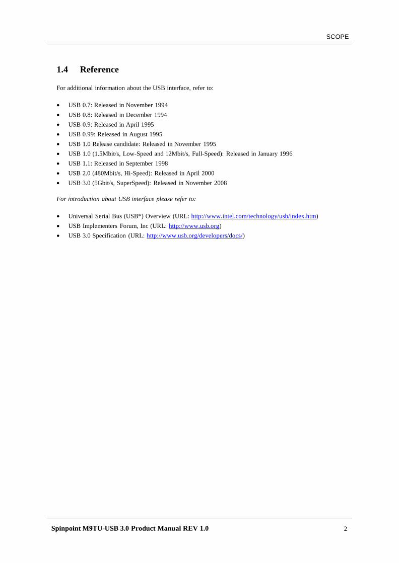
1.4 Reference
For additional information about the USB interface, refer to:
• USB 0.7: Released in November 1994 • USB 0.8: Released in December 1994 • USB 0.9: Released in April 1995 • USB 0.99: Released in August 1995 • USB 1.0 Release candidate: Released in November 1995 • USB 1.0 (1.5Mbit/s, Low-Speed and 12Mbit/s, Full-Speed): Released in January 1996 • USB 1.1: Released in September 1998 • USB 2.0 (480Mbit/s, Hi-Speed): Released in April 2000 • USB 3.0 (5Gbit/s, SuperSpeed): Released in November 2008
For introduction about USB interface please refer to:
• Universal Serial Bus (USB*) Overview (URL: http://www.intel.com/technology/usb/index.htm) • USB Implementers Forum, Inc (URL: http://www.usb.org) • USB 3.0 Specification (URL: http://www.usb.org/developers/docs/)
Spinpoint M9TU-USB 3.0 Product Manual REV 1.0 3
DESCRIPTION
CHAPTER 2 DESCRIPTION
This chapter summarizes general functions and key features of the Spinpoint M9TU-USB 3.0 hard disk drive, as well as the standards and regulations they meet.
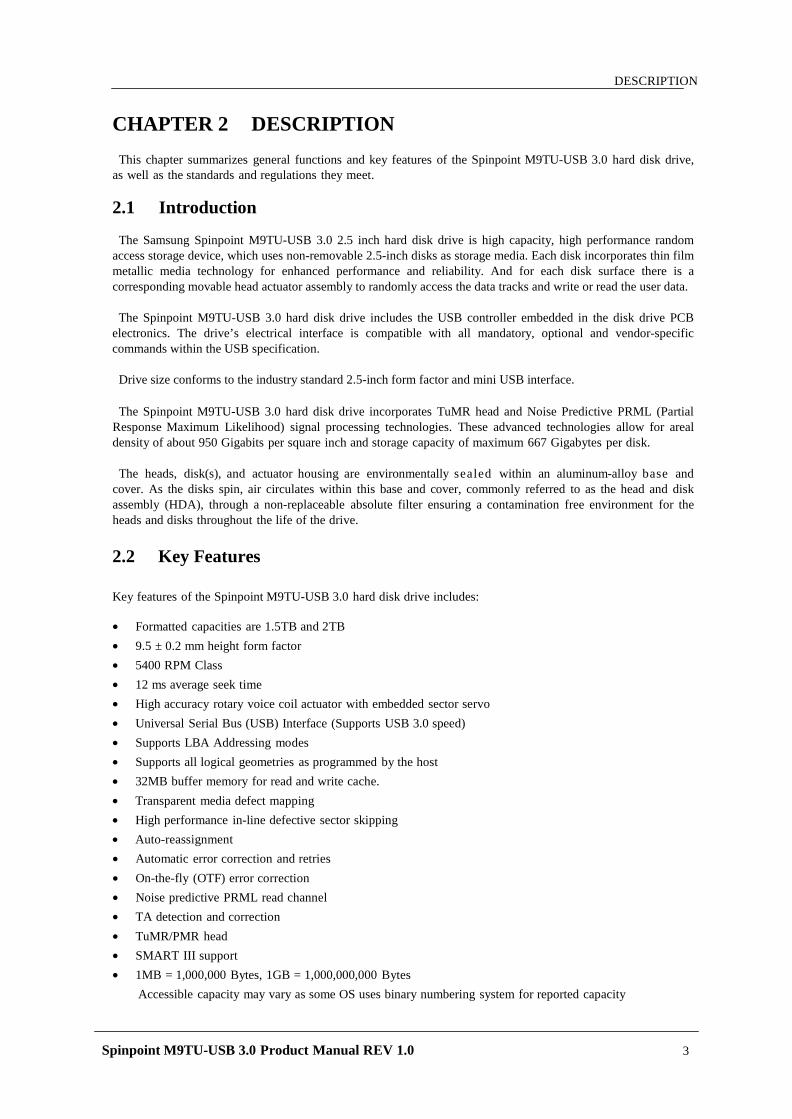
2.1 Introduction The Samsung Spinpoint M9TU-USB 3.0 2.5 inch hard disk drive is high capacity, high performance random
access storage device, which uses non-removable 2.5-inch disks as storage media. Each disk incorporates thin film metallic media technology for enhanced performance and reliability. And for each disk surface there is a corresponding movable head actuator assembly to randomly access the data tracks and write or read the user data. The Spinpoint M9TU-USB 3.0 hard disk drive includes the USB controller embedded in the disk drive PCB
electronics. The drive’s electrical interface is compatible with all mandatory, optional and vendor-specific commands within the USB specification.
Drive size conforms to the industry standard 2.5-inch form factor and mini USB interface.
The Spinpoint M9TU-USB 3.0 hard disk drive incorporates TuMR head and Noise Predictive PRML (Partial
Response Maximum Likelihood) signal processing technologies. These advanced technologies allow for areal density of about 950 Gigabits per square inch and storage capacity of maximum 667 Gigabytes per disk.
The heads, disk(s), and actuator housing are environmentally sealed within an aluminum-alloy base and
cover. As the disks spin, air circulates within this base and cover, commonly referred to as the head and disk assembly (HDA), through a non-replaceable absolute filter ensuring a contamination free environment for the heads and disks throughout the life of the drive.
2.2 Key Features
Key features of the Spinpoint M9TU-USB 3.0 hard disk drive includes: • Formatted capacities are 1.5TB and 2TB • 9.5 ± 0.2 mm height form factor • 5400 RPM Class • 12 ms average seek time • High accuracy rotary voice coil actuator with embedded sector servo • Universal Serial Bus (USB) Interface (Supports USB 3.0 speed) • Supports LBA Addressing modes • Supports all logical geometries as programmed by the host • 32MB buffer memory for read and write cache. • Transparent media defect mapping • High performance in-line defective sector skipping • Auto-reassignment • Automatic error correction and retries • On-the-fly (OTF) error correction • Noise predictive PRML read channel • TA detection and correction • TuMR/PMR head • SMART III support • 1MB = 1,000,000 Bytes, 1GB = 1,000,000,000 Bytes
Accessible capacity may vary as some OS uses binary numbering system for reported capacity
Spinpoint M9TU-USB 3.0 Product Manual REV 1.0 4
DESCRIPTION
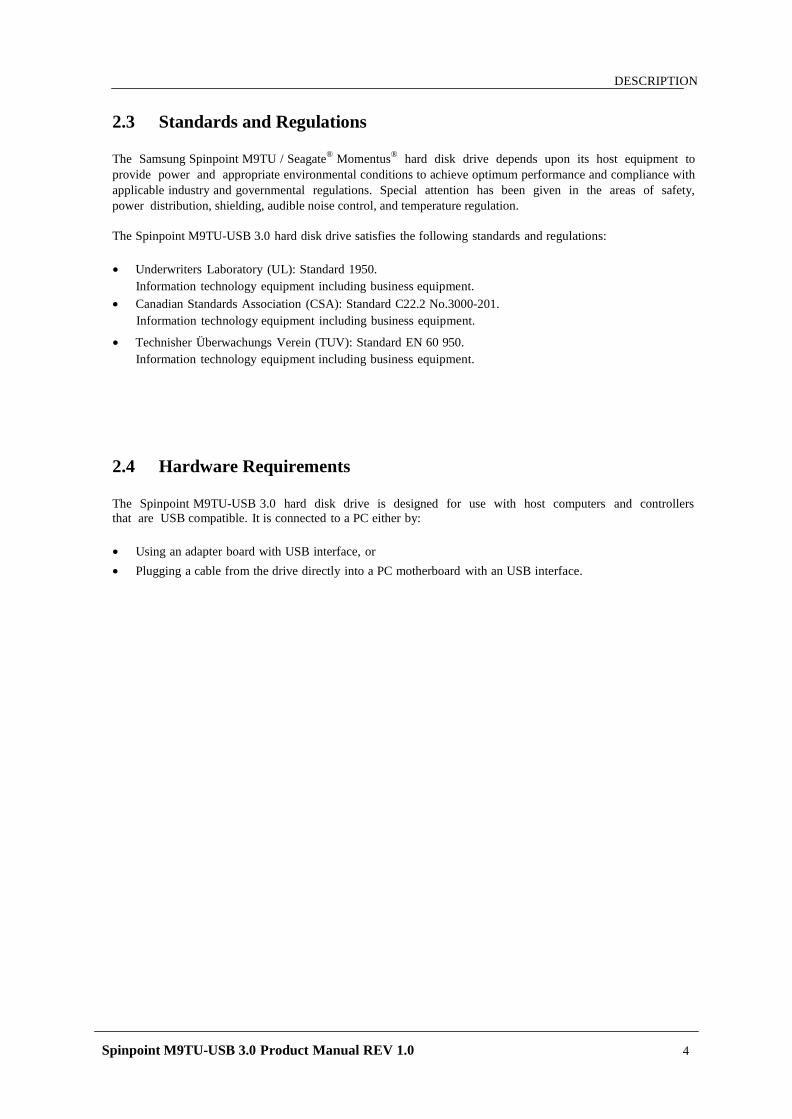
2.3 Standards and Regulations
The Samsung Spinpoint M9TU / Seagate® Momentus® hard disk drive depends upon its host equipment to provide power and appropriate environmental conditions to achieve optimum performance and compliance with applicable industry and governmental regulations. Special attention has been given in the areas of safety, power distribution, shielding, audible noise control, and temperature regulation.
The Spinpoint M9TU-USB 3.0 hard disk drive satisfies the following standards and regulations:
• Underwriters Laboratory (UL): Standard 1950.
Information technology equipment including business equipment. • Canadian Standards Association (CSA): Standard C22.2 No.3000-201.
Information technology equipment including business equipment.
• Technisher Überwachungs Verein (TUV): Standard EN 60 950. Information technology equipment including business equipment.
2.4 Hardware Requirements
The Spinpoint M9TU-USB 3.0 hard disk drive is designed for use with host computers and controllers that are USB compatible. It is connected to a PC either by:
• Using an adapter board with USB interface, or • Plugging a cable from the drive directly into a PC motherboard with an USB interface.
Spinpoint M9TU-USB 3.0 Product Manual REV 1.0 5
SPECIFICATIONS
CHAPTER 3 SPECIFICATIONS
This chapter gives a detail description of the physical, electrical and environmental characteristics of the Spinpoint M9TU-USB 3.0 hard disk drive.
3.1 Specification Summary
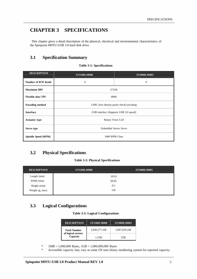
Table 3-1: Specifications
DESCRIPTION ST1500LM008 ST2000LM005
Number of R/W heads
6
6
Maximum BPI
2731K
Flexible data TPI
480K
Encoding method
LDPC (low density parity check) encoding
Interface
USB interface (Supports USB 3.0 speed)
Actuator type
Rotary Voice Coil
Servo type
Embedded Sector Servo
Spindle Speed (RPM)
5400 RPM Class
3.2 Physical Specifications
Table 3-2: Physical Specifications
DESCRIPTION ST1500LM008 ST2000LM005
Length (mm)
Width (mm)
Height (mm)
Weight (g, max)
103.9
69.85
9.5
130
3.3 Logical Configurations
Table 3-3: Logical Configurations
DESCRIPTION ST1500LM008 ST2000LM005
Total Number of logical sectors
Capacity
2,930,277,168 3,907,029,168
1.5TB 2TB
* 1MB = 1,000,000 Bytes, 1GB = 1,000,000,000 Bytes * Accessible capacity may vary as some OS uses binary numbering system for reported capacity.
Spinpoint M9TU-USB 3.0 Product Manual REV 1.0 6
SPECIFICATIONS
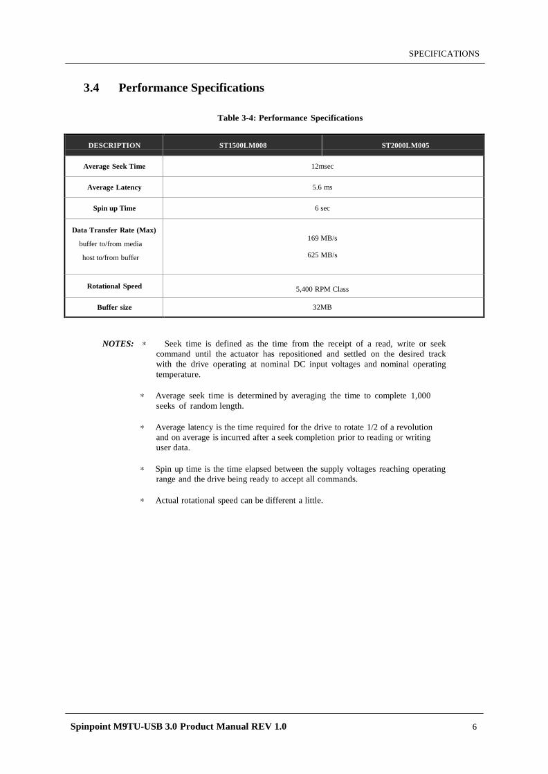
3.4 Performance Specifications
Table 3-4: Performance Specifications
DESCRIPTION ST1500LM008 ST2000LM005
Average Seek Time 12msec
Average Latency 5.6 ms
Spin up Time 6 sec
Data Transfer Rate (Max)
buffer to/from media
host to/from buffer
169 MB/s
625 MB/s
Rotational Speed 5,400 RPM Class
Buffer size 32MB
NOTES: ∗ Seek time is defined as the time from the receipt of a read, write or seek command until the actuator has repositioned and settled on the desired track with the drive operating at nominal DC input voltages and nominal operating temperature.
∗ Average seek time is determined by averaging the time to complete 1,000
seeks of random length.
∗ Average latency is the time required for the drive to rotate 1/2 of a revolution and on average is incurred after a seek completion prior to reading or writing user data.
∗ Spin up time is the time elapsed between the supply voltages reaching operating
range and the drive being ready to accept all commands.
∗ Actual rotational speed can be different a little.
Spinpoint M9TU-USB 3.0 Product Manual REV 1.0 7
SPECIFICATIONS
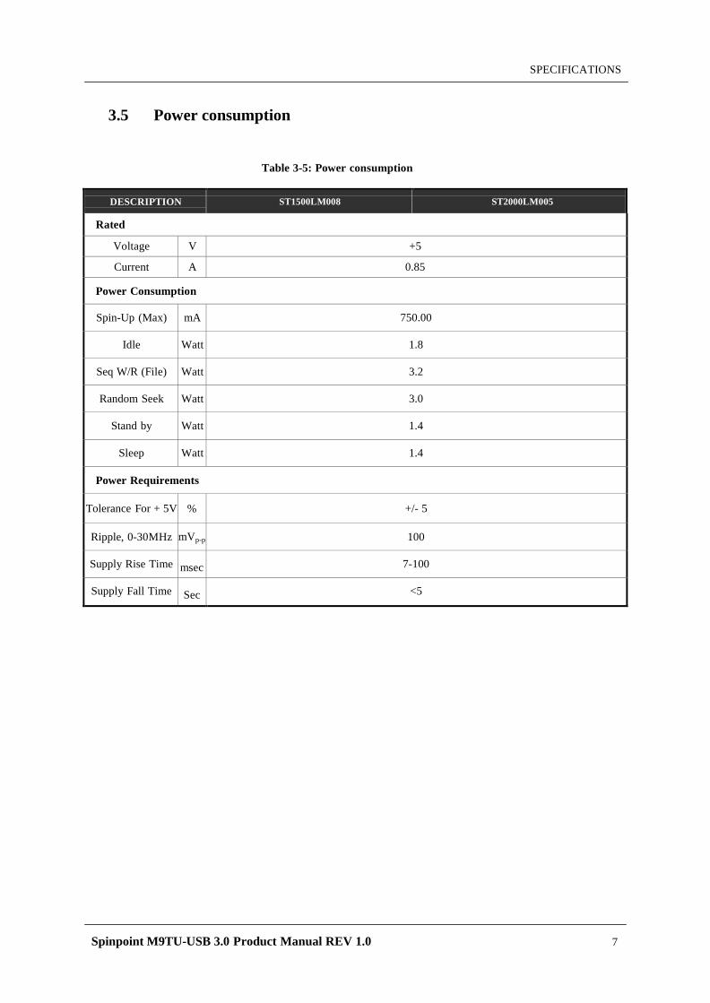
3.5 Power consumption
Table 3-5: Power consumption
DESCRIPTION ST1500LM008 ST2000LM005
Rated
Voltage V +5
Current A 0.85
Power Consumption
Spin-Up (Max)
mA
750.00
Idle
Watt
1.8
Seq W/R (File)
Watt
3.2
Random Seek
Watt
3.0
Stand by
Watt
1.4
Sleep
Watt
1.4
Power Requirements
Tolerance For + 5V %
+/- 5
Ripple, 0-30MHz mVp-p
100
Supply Rise Time
msec
7-100
Supply Fall Time
Sec
<5
Spinpoint M9TU-USB 3.0 Product Manual REV 1.0 8
SPECIFICATIONS
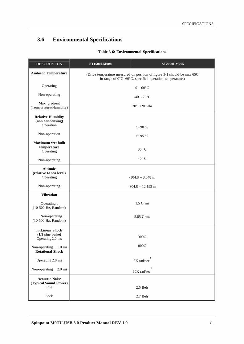
3.6 Environmental Specifications
Table 3-6: Environmental Specifications
DESCRIPTION ST1500LM008 ST2000LM005
Ambient Temperature
Operating
Non-operating
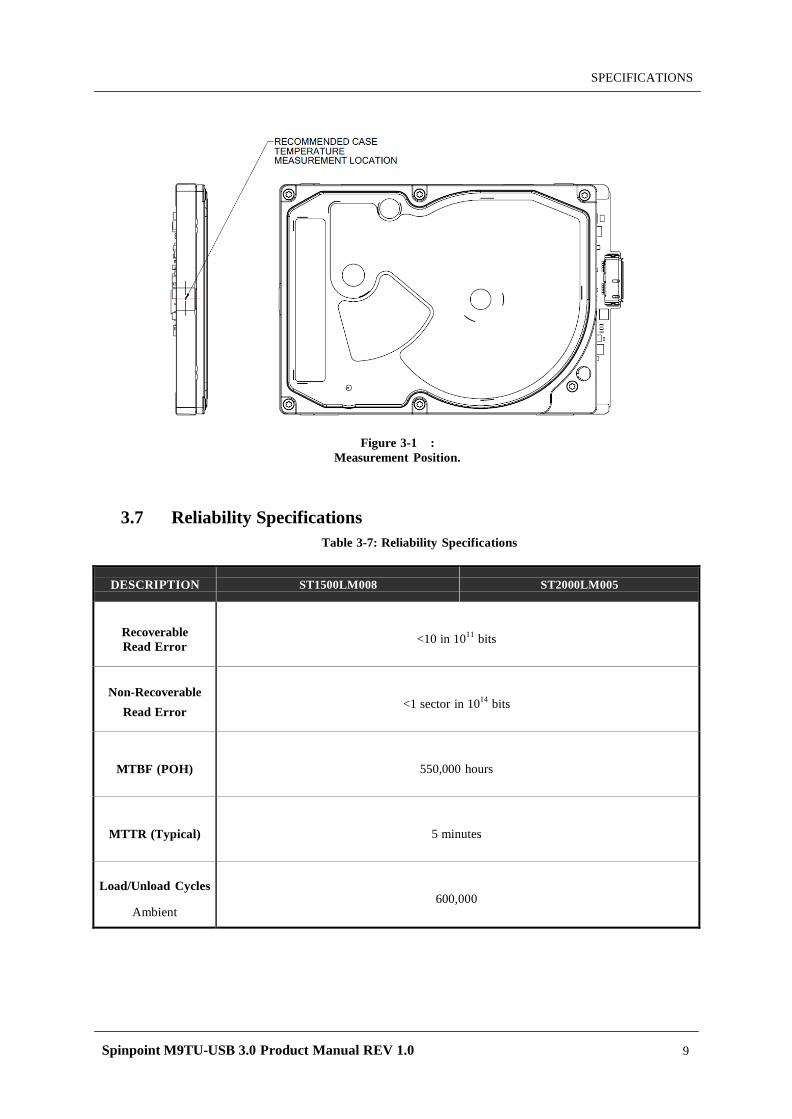
Max. gradient (Temperature/Humidity)
(Drive temperature measured on position of figure 3-1 should be max 65C in range of 0°C -60°C, specified operation temperature.)
0 ∼ 60°C
-40 ∼ 70°C
20°C/20%/hr
Relative Humidity (non condensing)
Operation
Non-operation
Maximum wet bulb temperature
Operating
Non-operating
5~90 %
5~95 %
30° C
40° C
Altitude (relative to sea level)
Operating
Non-operating
-304.8 ∼ 3,048 m
-304.8 ∼ 12,192 m
Vibration
Operating : (10-500 Hz, Random)
Non-operating :
(10-500 Hz, Random)
1.5 Grms
5.85 Grms
mtLinear Shock (1/2 sine pulse) Operating 2.0 ms
Non-operating 1.0 ms
Rotational Shock
Operating 2.0 ms
Non-operating 2.0 ms
300G
800G
3K rad/sec2
30K rad/sec2
Acoustic Noise (Typical Sound Power)
Idle
Seek
2.5 Bels
2.7 Bels
Spinpoint M9TU-USB 3.0 Product Manual REV 1.0 9
SPECIFICATIONS
Figure 3-1 : Measurement Position.
3.7 Reliability Specifications
Table 3-7: Reliability Specifications
DESCRIPTION ST1500LM008 ST2000LM005
Recoverable Read Error
<10 in 1011 bits
Non-Recoverable Read Error
<1 sector in 1014 bits
MTBF (POH)
550,000 hours
MTTR (Typical)
5 minutes
Load/Unload Cycles
Ambient
600,000
Spinpoint M9TU-USB 3.0 Product Manual REV 1.0 10
INSTALLATION
CHAPTER 4 INSTALLATION
This chapter describes how to unpack, mount, configure and connect a Spinpoint M9TU-USB 3.0 hard disk drive. It also describes how to install the drive in systems.
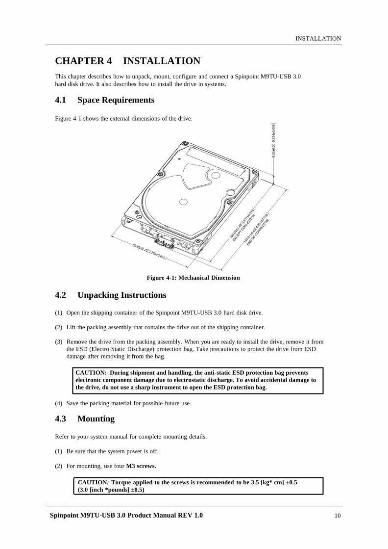
4.1 Space Requirements
Figure 4-1 shows the external dimensions of the drive.
Figure 4-1: Mechanical Dimension
4.2 Unpacking Instructions
(1) Open the shipping container of the Spinpoint M9TU-USB 3.0 hard disk drive.
(2) Lift the packing assembly that contains the drive out of the shipping container.
(3) Remove the drive from the packing assembly. When you are ready to install the drive, remove it from the ESD (Electro Static Discharge) protection bag. Take precautions to protect the drive from ESD damage after removing it from the bag.
CAUTION: During shipment and handling, the anti-static ESD protection bag prevents electronic component damage due to electrostatic discharge. To avoid accidental damage to the drive, do not use a sharp instrument to open the ESD protection bag.
(4) Save the packing material for possible future use.
4.3 Mounting
Refer to your system manual for complete mounting details.
(1) Be sure that the system power is off.
(2) For mounting, use four M3 screws.
CAUTION: Torque applied to the screws is recommended to be 3.5 [kg* cm] ±0.5 (3.0 [inch *pounds] ±0.5)
Spinpoint M9TU-USB 3.0 Product Manual REV 1.0 11
INSTALLATION
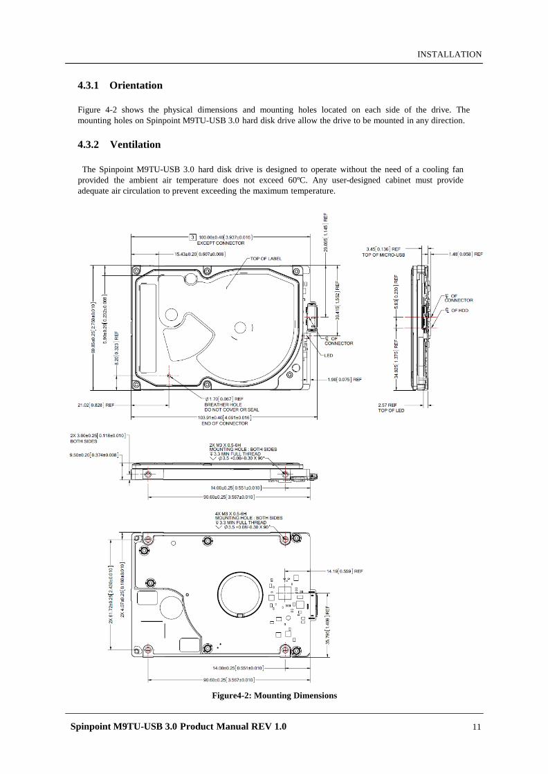
4.3.1 Orientation
Figure 4-2 shows the physical dimensions and mounting holes located on each side of the drive. The mounting holes on Spinpoint M9TU-USB 3.0 hard disk drive allow the drive to be mounted in any direction.
4.3.2 Ventilation
The Spinpoint M9TU-USB 3.0 hard disk drive is designed to operate without the need of a cooling fan
provided the ambient air temperature does not exceed 60ºC. Any user-designed cabinet must provide adequate air circulation to prevent exceeding the maximum temperature.
Figure4-2: Mounting Dimensions
Spinpoint M9TU-USB 3.0 Product Manual REV 1.0 12
INSTALLATION
4.4 Cable Connectors
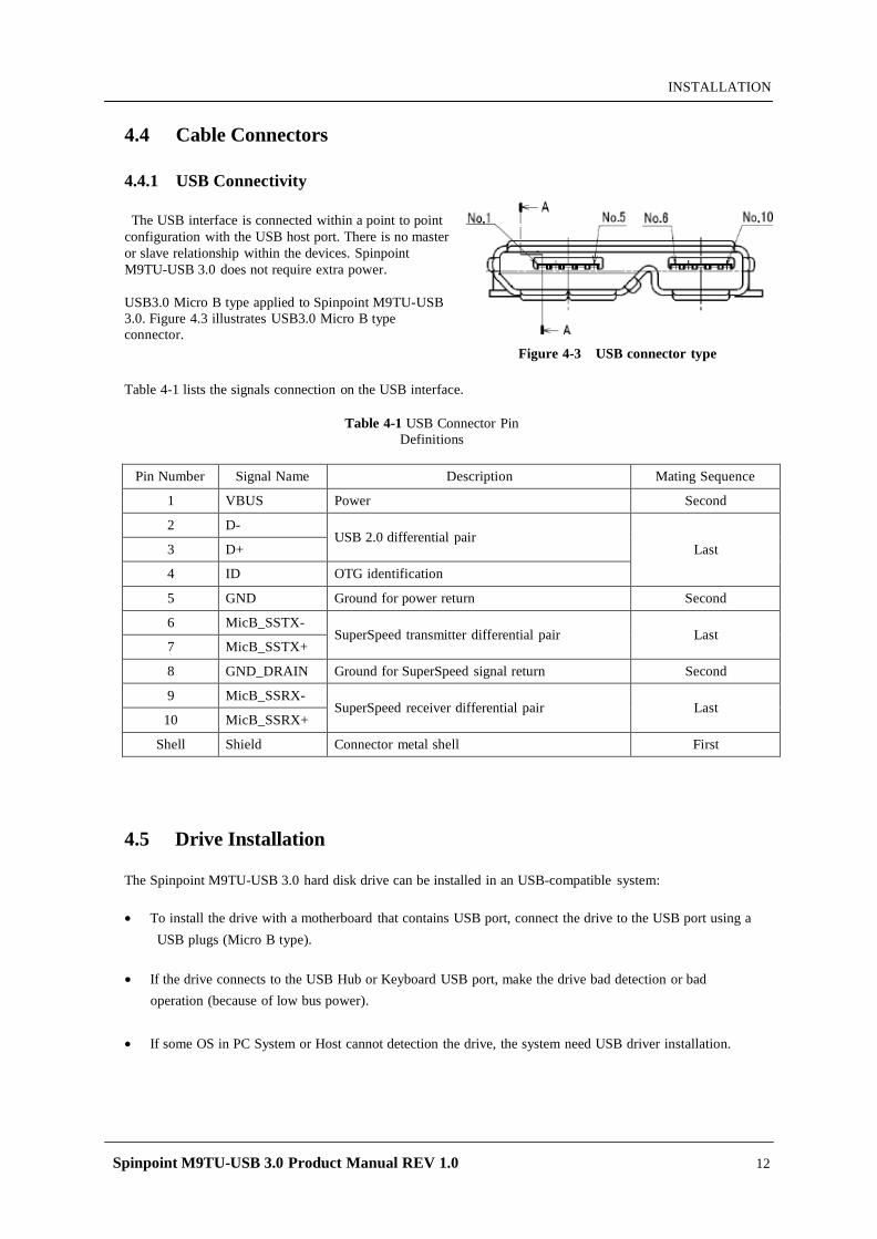
4.4.1 USB Connectivity
The USB interface is connected within a point to point configuration with the USB host port. There is no master or slave relationship within the devices. Spinpoint M9TU-USB 3.0 does not require extra power.
USB3.0 Micro B type applied to Spinpoint M9TU-USB 3.0. Figure 4.3 illustrates USB3.0 Micro B type connector.
Figure 4-3 USB connector type
Table 4-1 lists the signals connection on the USB interface.
Table 4-1 USB Connector Pin Definitions
Pin Number Signal Name Description Mating Sequence
1 VBUS Power Second
2 D- USB 2.0 differential pair
Last 3 D+
4 ID OTG identification
5 GND Ground for power return Second
6 MicB_SSTX- SuperSpeed transmitter differential pair
Last
7 MicB_SSTX+
8 GND_DRAIN Ground for SuperSpeed signal return Second
9 MicB_SSRX- SuperSpeed receiver differential pair
Last
10 MicB_SSRX+
Shell Shield Connector metal shell First
4.5 Drive Installation
The Spinpoint M9TU-USB 3.0 hard disk drive can be installed in an USB-compatible system:
• To install the drive with a motherboard that contains USB port, connect the drive to the USB port using a
USB plugs (Micro B type).
• If the drive connects to the USB Hub or Keyboard USB port, make the drive bad detection or bad
operation (because of low bus power).
• If some OS in PC System or Host cannot detection the drive, the system need USB driver installation.
Spinpoint M9TU-USB 3.0 Product Manual REV 1.0 13
INSTALLATION
4.6 System Startup Procedure
Once the Spinpoint M9TU-USB 3.0 hard disk drive and along with the adapter board (if required) have been installed in your system, the drive can now be partitioned and formatted for operation. To set up the drive correctly, follow these instructions:
1. Power on the system.
2. Typically the system will detect a configuration change automatically. If so, then jump to step 5.
3. Connected Drive Detection normally as removable disk but cannot access drive folder, please create
partition & format first.
4. Perform the following steps that applies to your system: (example for XP)
I. Select Control Panel - Computer Management - Disk Manager in OS Utility. II. Click the right mouse button of Selected USB device disk, and select New Partition. III. Step 1. Click Next Button. IV. Step 2. Select Partition Type and Click Next Button. V. Step3. Select Partition Size and Click Next Button VI. Step 4. Assign Drive Letter and Click Next Button. VII. Step 5. Select File System, quick format option and Click Next Button. VIII. Step 6. Click Finish Button
5. If the system recognizes the drive but experiences problem on properly handling the full capacity of the
drive, run Disk Manager utility program provided by Seagate and follow the instructions. The Disk Manager utility program is available from Seagate on a floppy diskette, or downloadable from the Seagate website at http://www.seagate.com. If, after all these steps are successfully completed, your system will not boot up, then contact technical support.
Table 4-2: Logical Drive Parameters
DESCRIPTION ST1500LM008 ST2000LM005
Total Number of logical sectors
Capacity
2,930,277,168 3,907,029,168
1.5TB 2TB
NOTES: • The total numbers of sectors is calculated by (Cylinders x Heads x Sectors) of the selected drive
type. • 1MB = 1,000,000 Bytes, 1GB = 1,000,000,000 Bytes
Accessible capacity may vary as some OS uses binary numbering system for reported capacity. • Windows 95 or 98 that use FAT16 file system will limit the drive’s logical partition at 2.1GB
per logical drive. Windows95 OSR2 or later allow for the FAT32 file system which provides access to greater than 2GB of logical capacity.
• A low-level format is not required, as this was done at the factory before shipment.
Spinpoint M9TU-USB 3.0 Product Manual REV 1.0 14
INSTALLATION
CHAPTER 5 DISK DRIVE OPERATION
This chapter describes the operation of the Spinpoint M9TU-USB 3.0 hard disk drive functional subsystems. It is intended as a guide to the operation of the drive, rather than a detailed theory of operation.
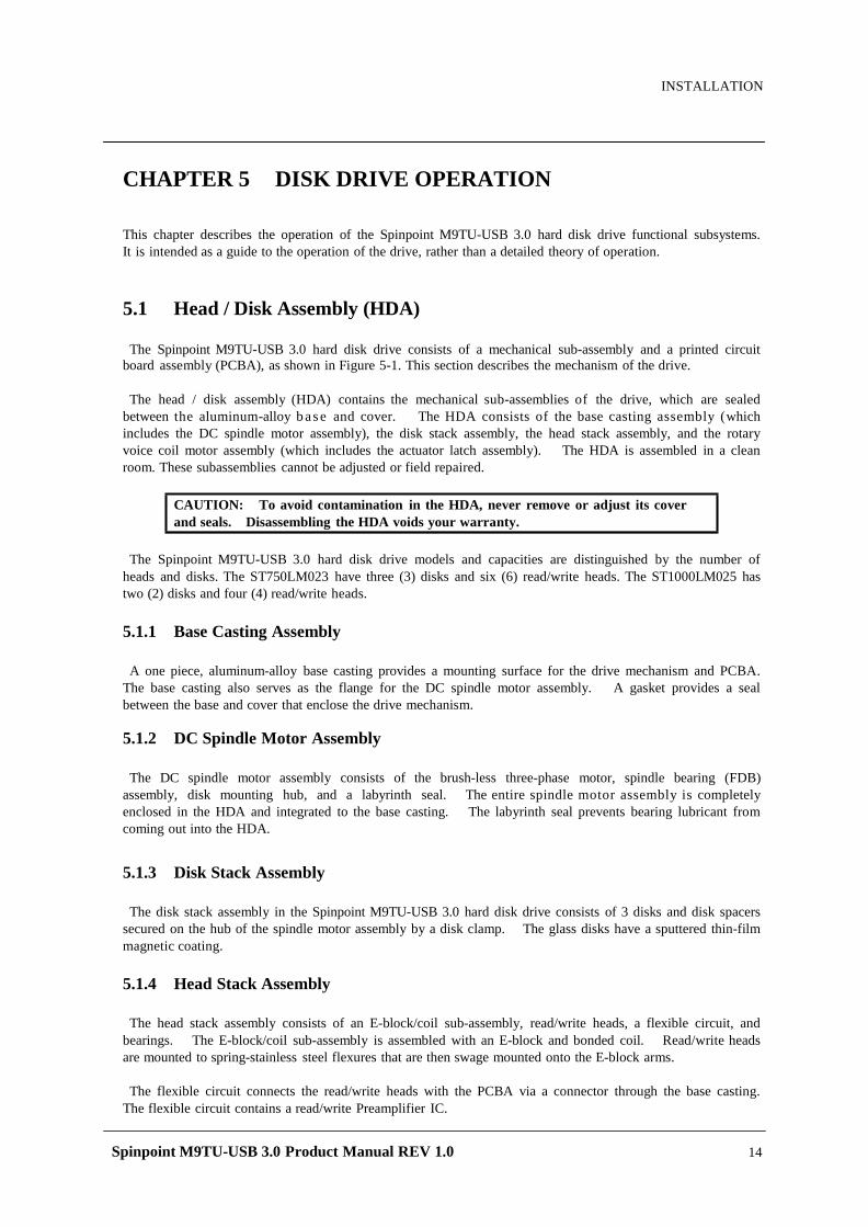
5.1 Head / Disk Assembly (HDA)
The Spinpoint M9TU-USB 3.0 hard disk drive consists of a mechanical sub-assembly and a printed circuit
board assembly (PCBA), as shown in Figure 5-1. This section describes the mechanism of the drive.
The head / disk assembly (HDA) contains the mechanical sub-assemblies of the drive, which are sealed between the aluminum-alloy b a s e and cover. The HDA consists of the base casting assembly (which includes the DC spindle motor assembly), the disk stack assembly, the head stack assembly, and the rotary voice coil motor assembly (which includes the actuator latch assembly). The HDA is assembled in a clean room. These subassemblies cannot be adjusted or field repaired.
CAUTION: To avoid contamination in the HDA, never remove or adjust its cover and seals. Disassembling the HDA voids your warranty.
The Spinpoint M9TU-USB 3.0 hard disk drive models and capacities are distinguished by the number of
heads and disks. The ST750LM023 have three (3) disks and six (6) read/write heads. The ST1000LM025 has two (2) disks and four (4) read/write heads.
5.1.1 Base Casting Assembly
A one piece, aluminum-alloy base casting provides a mounting surface for the drive mechanism and PCBA.
The base casting also serves as the flange for the DC spindle motor assembly. A gasket provides a seal between the base and cover that enclose the drive mechanism.
5.1.2 DC Spindle Motor Assembly
The DC spindle motor assembly consists of the brush-less three-phase motor, spindle bearing (FDB)
assembly, disk mounting hub, and a labyrinth seal. The entire spindle motor assembly is completely enclosed in the HDA and integrated to the base casting. The labyrinth seal prevents bearing lubricant from coming out into the HDA.
5.1.3 Disk Stack Assembly
The disk stack assembly in the Spinpoint M9TU-USB 3.0 hard disk drive consists of 3 disks and disk spacers
secured on the hub of the spindle motor assembly by a disk clamp. The glass disks have a sputtered thin-film magnetic coating.
5.1.4 Head Stack Assembly
The head stack assembly consists of an E-block/coil sub-assembly, read/write heads, a flexible circuit, and
bearings. The E-block/coil sub-assembly is assembled with an E-block and bonded coil. Read/write heads are mounted to spring-stainless steel flexures that are then swage mounted onto the E-block arms.
The flexible circuit connects the read/write heads with the PCBA via a connector through the base casting.
The flexible circuit contains a read/write Preamplifier IC.

Spinpoint M9TU-USB 3.0 Product Manual REV 1.0 15
INSTALLATION
Figure 5-1: Exploded Mechanical View
5.1.5 Voice Coil Motor and Actuator Latch Assemblies
The rotary voice coil motor consists of upper and lower permanent magnets and magnetic yokes fixed to the base casting and a rotary bonded coil on the head stack assembly. Each magnet consists of two alternating poles and is attached to the magnet yoke. Pawl latch and rubber crash stops mounted on a magnetic yoke physically prevent the head(s) from moving beyond the designed inner boundary into the spindle or off the disk surface. Current from the power amplifier induces a magnetic field in the voice coil. Fluctuations in the field around
the permanent magnets move the voice coil so that heads can be positioned in the requested cylinder.
5.1.6 Air Filtration System
Heads fly very close to the disk surfaces. Therefore, it is very important that air circulating within the drive be maintained free of particles. Seagate HDAs are assembled in a purified air environment to ensure cleanliness and then sealed with a gasket. To retain this clean air environment, the Spinpoint M9TU-USB 3.0 hard disk drive is equipped with a re-circulating filter, which is located in the path of the airflow close to the rotating disk and is designed to trap any particles that may develop inside HDA.
DISK DRIVE OPERATION
Spinpoint M9TU-USB 3.0 Product Manual REV 1.0
16
5.1.7 Load/Unload Mechanism
Portable computer is exposed to heavy handling environment comparing with desk top computer. Load/Unload
mechanism provides to protect data loss caused by head hitting to disk due to the abnormal shock and vibration in the transportation and handling. When power is shut down, head will move to parking position on the ramp.
5.2 D r iv e Electronics
The Spinpoint M9TU-USB 3.0 hard disk drive attains its intelligence and performance through the
specialized electronic components mounted on the PCBA. The components are mounted on one side of the PCBA.
The Preamplifier IC is the only electrical component that is not on the PCBA. It is mounted on the flexible
circuit inside the HDA. Locating the Preamplifier IC as close as possible to the read/write heads via surface mount technology improves the signal to noise ratio.
5.2.1 Digital Signal Process and Interface Controller
The DSP core controller has a dual ARM CPU that incorporates a true 16-bit digital signal processor (DSP),
a bus controller unit (BCU), an interrupt controller unit (ICU), a general purpose timer (GPT), and SRAM
5.2.2 USB Interface Controller
The USB interface disk controller works in conjunction with the DSP core to perform the USB interface
control, buffer data flow management, disk format/read/write control, and error correction functions of an embedded disk drive controller. The DSP communicates with the disk controller module by reading from and writing to its various internal registers.
To the DSP core, the registers of the disk controller appear as unique memory or I/O locations that are
randomly accessed and operated upon. By reading from and writing to the registers, the DSP core initiates operations and examines the status of the different functional blocks. Once an operation is started, successful completion or an error condition may cause the disk controller to interrupt the DSP core, which then examines the status registers of the disk controller and determines an appropriate course of action. The local DSP core may also poll the device to ascertain successful completion or error conditions.
5.2.2.1 The Host Interface Control Block
The HBI module responds to the command issued from the host and controls the data transfer between the
buffer memory module and the host.
The HBI module supports the following main features: • Power Saving • 8/16 bit host interface • A deep FIFO (32 x 32 bit) used as the temporary buffer for the data transfer • 512 byte • Microprocessor Interrupts • 6 endpoints ( EP0-EP2 IN/OUT) • Mass Storage class bulk-only transport with flow control • Support Control transport • Support Suspend/resume mode
DISK DRIVE OPERATION
Spinpoint M9TU-USB 3.0 Product Manual REV 1.0
17
5.2.2.2 The Buffer Control Block
The Buffer Control block manages the flow of data into and out of the buffer. Significant automation allows buffer activity to take place automatically during read/write operations between the host and the disk. This automation works together with automation within the Host Interface Control and Disk Control blocks to provide more bandwidth for the local microprocessor to perform non-data flow functions.
The buffer control circuitry keeps track of buffer full and empty conditions and automatically works with the
Disk Control block to stop transfers to or from the disk when necessary. In addition, transfers to or from the host are automatically stopped or started based on buffer full or empty status.
Additional functionality is provided in the Buffer Control block through the following features:
• Increased automation to support minimal latency read operations with minimal latency. • Capability to support the execution of multiple consecutive Auto-Write commands without loss of data
due to overwriting of data. • Auto write pointer. • A disk sector counter that can monitor the transfers between the disk and buffer. • Read/Write cache support.
5.2.2.3 The Disk Control Block
The Disk Control block manages the flow of data between the disk and the buffer. Many flexible features and elements of automation have been incorporated to complement the automation contributed by the Host and Buffer blocks.
The Disk Control block consists of the programmable sequencer (Disk Sequencer), CDR/data split logic, disk FIFO, fault tolerant sync detect logic, and other support logic. The programmable sequencer contains a 32-by-4 byte programmable SRAM and associated control logic, which
is programmed by the user to automatically control all single track format, read, and write operations. From within the sequencer micro program, the Disk Control block can automatically deal with such real time functions as defect skipping, servo burst data splitting, branching on critical buffer status and data compare operations. Once the Disk Sequencer is started, it executes each word in logical order. At the completion of the current instruction word, it either continues to the next instruction, continues to execute some other instruction based upon an internal or external condition having been met, or it stops.
During instruction execution or while stopped, registers can be accessed by the DSP to obtain status
information reflecting the Disk Sequencer operations taking place.
5.2.2.4 The Disk ECC Control Block The Disk Control Block supports a programmable LDPC code. Error detection and correction is handled in
the Disk Control block. Automatic on-the-fly hardware correction will take place. Correction is guaranteed to complete before the parity bits of the sector following the sector where the error occurred utilizing standard ATA size sectors.
5.2.2.5 Power Management
Power management features are incorporated into each block of the Spinpoint M9TU-USB 3.0. This allows the designer to tailor the amount of power management to the specified design. Other power management features include: • Independent power management control for each block. • DSP block powered down and up when needed. • Disk Sequencer and associated disk logic powered up when the Disk Sequencer is started. • Weak pull-up structure on input pins to prevent undesirable power consumption due to floating CMOS inputs.
Spinpoint M9TU-USB 3.0 Product Manual REV 1.0 18
DISK DRIVE OPERATION
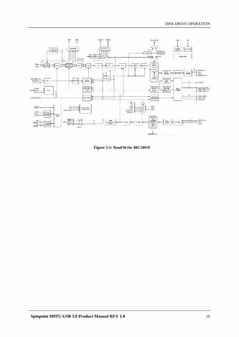
5.2.3 Read/Write IC
The Read/Write IC, shown in Figure 5-2 provides read/write-processing functions for the drive. The Read/Write IC receives the Read GATE and Write GATE signals, write data, and servo AGC and gates from the Interface Controller. The Read/Write IC sends decoded read data and the read reference clock. It receives write data from the Interface Controller. The 88C10010 which is embedded in 88i1022 is a sampled-data digital PRML channel designed to work
with a disk controller and a read/write preamplifier to provide the signal processing elements required to build a state of the art high density, high speed disk drive. The 88C10010 implements a noise predictive, PRML Viterbi read channel (supporting) zone-bit recording, The read/write channel functions include a time base generator, AGC circuitry, asymmetry correction
circuitry (ASC), analog anti-aliasing low-pass filter, analog to digital converter (ADC), digital FIR filter, timing recovery circuits, Viterbi detector, sync mark detection, 30/32 rate block code ENDEC, serializer and de-serializer, and write pre-compensation circuits. Servo functions include servo data detection and PES demodulation. Additionally the 88C10010 contains specialized circuitry to perform various parametric measurements on the processed read signal. This allows for implementation of self-tuning and optimization capability in every drive built using the 88C10010. A 12-bit NRZ interface is provided to support high speed data transfers and from the controller.
Programming of the 88C10010 is performed through a serial interface. The serial interface is also used to read various channel parameters that are computed on the fly.
5.2.3.1 Time Base Generator
The time base generator provides the write frequency and serves as a reference clock to the synchronizer during non-read mode.
5.2.3.2 Automatic Gain Control
The AGC accepts a differential signal from the pre-amp, and provide constant output amplitude to the analog filter. It’s capable of accepting signal ranges from 50 mV to 400 mVppd.
5.2.3.3 Asymmetry Correction Circuitry (ASC) The ASC circuit is designed to correct for amplitude asymmetry introduced by MR heads. The compensation
range of this circuit is +/-30%. This circuit allows optimal bias current to be used independent of the asymmetry effect.
5.2.3.4 Analog Anti-Aliasing Low Pass Filter
The 5th order equal-ripple analog filter provides filtering of the analog signal from AGC before it’s being converted to digital signal with the ADC. Its main function is to avoid aliasing for the ADC circuit.
5.2.3.5 Analog to Digital Converter (ADC) and FIR
The output of the analog filter is quantified using a 6 bit FLASH ADC. The digitized data is then equalized by the FIR to the NPV target response for Viterbi detection. The FIR filter consists of 10 independent programmable taps
Spinpoint M9TU-USB 3.0 Product Manual REV 1.0 19
DISK DRIVE OPERATION
Figure 5-2: Read/Write 88C10010
Spinpoint M9TU-USB 3.0 Product Manual REV 1.0 20
DISK DRIVE OPERATION
5.3 Se rv o System
The Servo System controls the position of the read/write heads and holds them on track during read/write
operations. The Servo System also compensates for MR write/read offsets and thermal offsets between heads on different surfaces and for vibration and shock applied to the drive. The Spinpoint M9TU-USB 3.0 hard disk drive is an Embedded Sector Servo System. Positioning
information is radically located in evenly spaced servo sectors on each track. Radial position information can be provided from these sectors for each data head. Because the drive
incorporates multiple data zones and each zone has a different bit density, split data fields are necessary for optimal use of the non-servo area of the disk. The servo area remains phase-coherent across the surface of the disk, even though the disk has various data zones. The main advantage of the Embedded Sector Servo System is that it eliminates the problems of static and dynamic offsets between heads on different surfaces. The Spinpoint M9TU-USB 3.0 hard disk drive Servo System is classified as a digital servo system because track-following and seek control, bias cancellation, and other typical tasks are done in a Digital Signal Processor (DSP). The Servo system has three modes of operation: track-following mode, settle mode, and velocity control
mode.
1. Track-following mode is used when heads are “on-track.” This is a position loop with an integrator in the compensation.
2. Settle mode is used for all accesses; head switches, short-track seeks and long-track seeks. Settle mode is a position loop with velocity damping. Settle mode does not use feed forward.
3. Velocity control mode is used for acceleration and deceleration of the actuator for seeking of two or more tracks. A seek operation of this length is accomplished with a velocity control loop. The drive’s ROM stores the velocity profile in a look-up table.
5.4 R ea d and Write Operations
The following two sections describe the read and write channels.
5.4.1 The Read Channel
The drive has one read/write head for each of the data surfaces. The signal path for the Read Channel starts at the read/write heads. When the magnetic flux transitions recorded on a disk pass under the head, they generate low-amplitude, differential output voltages. The read/write head transfers these signals to the flexible circuit’s amplifier, which amplifies the signal. The flexible circuit transmits the pre-amplified signal from the HDA to the PCBA. The EPRML channel on the PCBA shapes, filters, detects, synchronizes, and decodes the data from the disk. The Read/Write IC then sends the resynchronized data output to the 88i1022 DSP & Interface/Disk Controller. The 88i1022 Disk Controller manages the flow of data between the Data Synchronizer on the Read/Write IC and its AT Interface Controller. It also controls data access for the external RAM buffer. The ENDEC of 88C10010 decodes the LDPC with post-processor format to produce a serial bit stream. This NRZ (Non Return to Zero) serial data is converted to 12-bits. The Sequencer module identifies the data as belonging to the target sector. After a full sector is read, the 88i1022 checks to see if the firmware needs to apply an ECC algorithm to the data. The Buffer Control section of the 88i1022 stores the data in the cache and transmits the data to the AT bus.
Spinpoint M9TU-USB 3.0 Product Manual REV 1.0 21
DISK DRIVE OPERATION
5.4.2 The Write Channel
The signal path for the Write Channel follows the reverse order of that for the Read Channel. The host transmits data via the AT bus to the 88i1022 Interface Controller. The Buffer Controller section of the 88i1022 stores the data in the cache. Because the data is transmitted to the drive at a rate that exceeds the rate at which the drive can write data to the disk, data is stored temporarily in the cache. Thus, the host can present data to the drive at a rate independent of the rate at which the drive can write data to the disk. Upon correct identification of the target address, the data is shifted to the Sequencer, which generates and appends an error correcting code. The Sequencer then converts the bytes of data to a serial bit stream. The AT controller also generates a preamble field, inserts an address mark, and transmits the data to the ENDEC in the R/W IC where the data is encoded into the LDPC format and pre-compensates for non-linear transition shift. The amount of write current is set by the 88i1022 DSP and Interface/Disk Controller through the serial interface to the preamplifier. The 88i1022 switches the Preamplifier and Write Driver IC to write mode and selects a head. Once the Preamplifier and Write Driver IC receives a write gate signal, it transmits current reversals to the head, which writes magnetic transitions on the disk.
5.5 F irmw a re Features
This section describes the following firmware features:
• Read Caching • Write Caching • Track Skewing • Defect Management • Automatic Defect Allocation • ECC Correction
5.5.1 Read Caching The Spinpoint M8U-USB 3.0 hard disk drive uses a 32MB Read Cache to enhance drive performance and
significantly improve system throughput. Use the SET FEATURES command to enable or disable Read Caching. Read caching anticipates host-system requests for data and stores that data for faster future access. When the host requests a certain segment of data, the cache feature utilizes a prefetch strategy to get the data in advance and automatically read and store the following data from the disk into fast RAM. If the host requests this data, the RAM is accessed rather than the disk.
There is a high probability that subsequent data requested will be in the cache, because more than 50 percent of all disk requests are sequential. It takes microseconds rather than milliseconds to retrieve this cached data. Thus Read Caching can provide substantial time savings during at least half of all disk requests. For example, Read Caching could save most of the disk transaction time by eliminating the seek and rotational latency delays that prominently dominate the typical disk transaction. Read Caching operates by continuing to fill its cache memory with adjacent data after transferring data
requested by the host. Unlike a non-caching controller, the 88i1022 Interface Controller continues a read operation after the requested data has been transferred to the host system. This read operation terminates after a programmed amount of subsequent data has been read into the cache memory.
The cache memory consists of a 32MB sync DRAM buffer allocated to hold the data. It can be directly accessed by the host by means of read and write commands. The unit of data stored is the logical block, or a multiple of the 512-byte sector. Therefore, all accesses to cache memory must be in multiples of the sector size. The following commands empty the cache:
• IDENTIFY DRIVE (ECh) • FORMAT TRACK (50h) • EXECUTE DRIVE DIAGNOSTIC (90h) • READ LONG (23h) • WRITE VERIFY (3Ch)
Spinpoint M9TU-USB 3.0 Product Manual REV 1.0 22
DISK DRIVE OPERATION
• INITIALIZE DEVICE PARAMETER (91h) • SLEEP (99h, E6h) • STANDBY IMMEDIATELY (94h, E0h) • READ BUFFER (E4h) • WRITE BUFFER (E8h) • WRITE SAME (E9h)
5.5.2 Write Caching
Write caching improves both single and multi-sector write performance by reducing delays introduced by
rotational latency. When the drive writes a pattern of multiple sequential data, it stores the data to a cache buffer and immediately sends a COMMAND COMPLETE message to the host before it writes the data to the disk.
The data is then written collectively to the drive thereby minimizing the disk seeking operation. Data is
held in cache no longer than the maximum seek time plus rotational latency. Host retries must be enabled for Write Caching to be active.
If the data request is random, the data of the previous command is written to the disk before COMMAND
COMPLETE is posted for the current command. Read commands work similarly. The previous write is allowed to finish before the read operation starts.
If a defective sector is found during a write, the sector is automatically relocated before the write occurs.
This ensures that cached data that already has been reported as written successfully gets written, even if an error should occur.
If the sector is not automatically relocated, the drive drops out of write caching and reports the error as an ID
Not Found. If the write command is still active on the AT interface, the error is reported during that command. Otherwise, it is reported on the next command.
5.5.3 Defect Management
The Spinpoint M9TU-USB 3.0 hard disk drive media is scanned for defects. After defect scanning, the
defective sectors are saved in the defect list. A defect encountered in the manufacturing process is slipped to the next physical sector location. All logical sector numbers are pushed down to maintain a sequential order of data. The read/write operation can “slip” over the defective sectors so that the only performance impact is idle time.
5.5.4 Automatic Defect Allocation
The automatic defect allocation feature automatically maps out defective sectors encountered during read
sector or write sector operations. These types of defective sectors are typically caused by grown defects. During write operations, if write errors are encountered, all sectors within the target servo frame are mapped out. Original data is transferred and written into designated reserved sector areas determined by the HDD firmware.
5.5.5 Multi Parities Error Correction
The drive uses LDPC code with parity to perform error detection and correction. For each 4K bytes
block, the software error correction polynomial is capable of correcting:
• 320-bit burst error
These errors are corrected on the fly with no performance degradation.
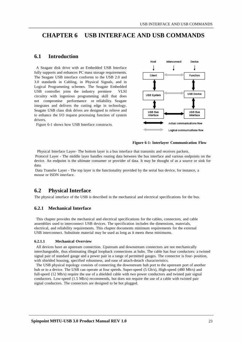
Spinpoint M9TU-USB 3.0 Product Manual REV 1.0 23
USB INTERFACE AND USB COMMANDS
CHAPTER 6 USB INTERFACE AND USB COMMANDS
6.1 Introduction
A Seagate disk drive with an Embedded USB Interface
fully supports and enhances PC mass storage requirements. The Seagate USB interface conforms to the USB 2.0 and 3.0 standards in Cabling, in Physical Signals, and in Logical Programming schemes. The Seagate Embedded USB controller joins the industry premiere VLSI circuitry with ingenious programming skill that does not compromise performance or reliability. Seagate integrates and delivers the cutting edge in technology. Seagate USB class disk drives are designed to relieve and to enhance the I/O request processing function of system drivers.
Figure 6-1 shows how USB Interface constructs.
Figure 6-1: Interlayer Communication Flow
Physical Interface Layer- The bottom layer is a bus interface that transmits and receives packets. Protocol Layer - The middle layer handles routing data between the bus interface and various endpoints on the device. An endpoint is the ultimate consumer or provider of data. It may be thought of as a source or sink for data. Data Transfer Layer - The top layer is the functionality provided by the serial bus device, for instance, a mouse or ISDN interface.
6.2 Physical Interface The physical interface of the USB is described in the mechanical and electrical specifications for the bus. 6.2.1 Mechanical Interface
This chapter provides the mechanical and electrical specifications for the cables, connectors, and cable
assemblies used to interconnect USB devices. The specification includes the dimensions, materials, electrical, and reliability requirements. This chapter documents minimum requirements for the external USB interconnect. Substitute material may be used as long as it meets these minimums.
6.2.1.1 Mechanical Overview All devices have an upstream connection. Upstream and downstream connectors are not mechanically
interchangeable, thus eliminating illegal loopback connections at hubs. The cable has four conductors: a twisted signal pair of standard gauge and a power pair in a range of permitted gauges. The connector is four- position, with shielded housing, specified robustness, and ease of attach-detach characteristics.
The USB physical topology consists of connecting the downstream hub port to the upstream port of another hub or to a device. The USB can operate at four speeds. Super-speed (5 Gb/s), High-speed (480 Mb/s) and full-speed (12 Mb/s) require the use of a shielded cable with two power conductors and twisted pair signal conductors. Low-speed (1.5 Mb/s) recommends, but does not require the use of a cable with twisted pair signal conductors. The connectors are designed to be hot plugged.
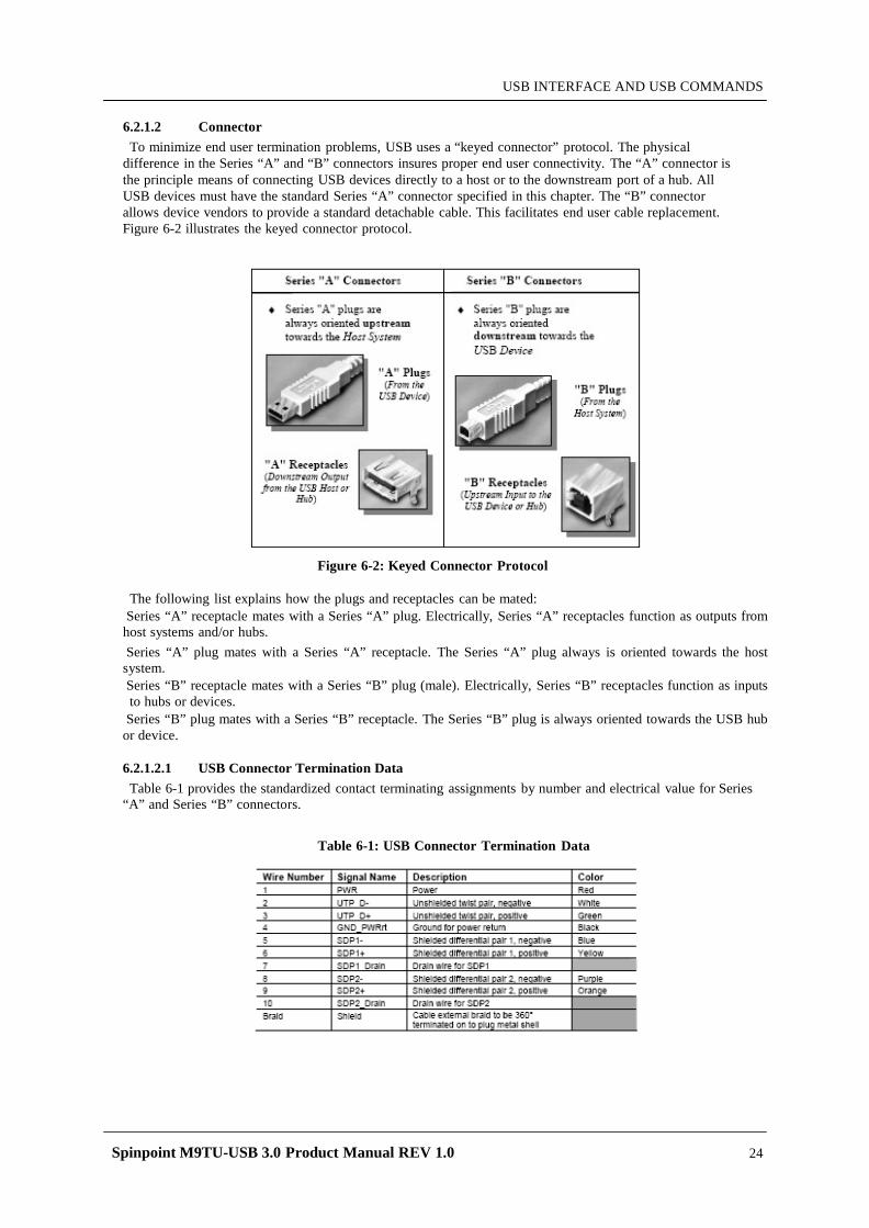
Spinpoint M9TU-USB 3.0 Product Manual REV 1.0 24
USB INTERFACE AND USB COMMANDS
6.2.1.2 Connector To minimize end user termination problems, USB uses a “keyed connector” protocol. The physical
difference in the Series “A” and “B” connectors insures proper end user connectivity. The “A” connector is the principle means of connecting USB devices directly to a host or to the downstream port of a hub. All USB devices must have the standard Series “A” connector specified in this chapter. The “B” connector allows device vendors to provide a standard detachable cable. This facilitates end user cable replacement. Figure 6-2 illustrates the keyed connector protocol.
Figure 6-2: Keyed Connector Protocol
The following list explains how the plugs and receptacles can be mated: Series “A” receptacle mates with a Series “A” plug. Electrically, Series “A” receptacles function as outputs from host systems and/or hubs. Series “A” plug mates with a Series “A” receptacle. The Series “A” plug always is oriented towards the host system. Series “B” receptacle mates with a Series “B” plug (male). Electrically, Series “B” receptacles function as inputs to hubs or devices.
Series “B” plug mates with a Series “B” receptacle. The Series “B” plug is always oriented towards the USB hub or device. 6.2.1.2.1 USB Connector Termination Data Table 6-1 provides the standardized contact terminating assignments by number and electrical value for Series
“A” and Series “B” connectors.
Table 6-1: USB Connector Termination Data
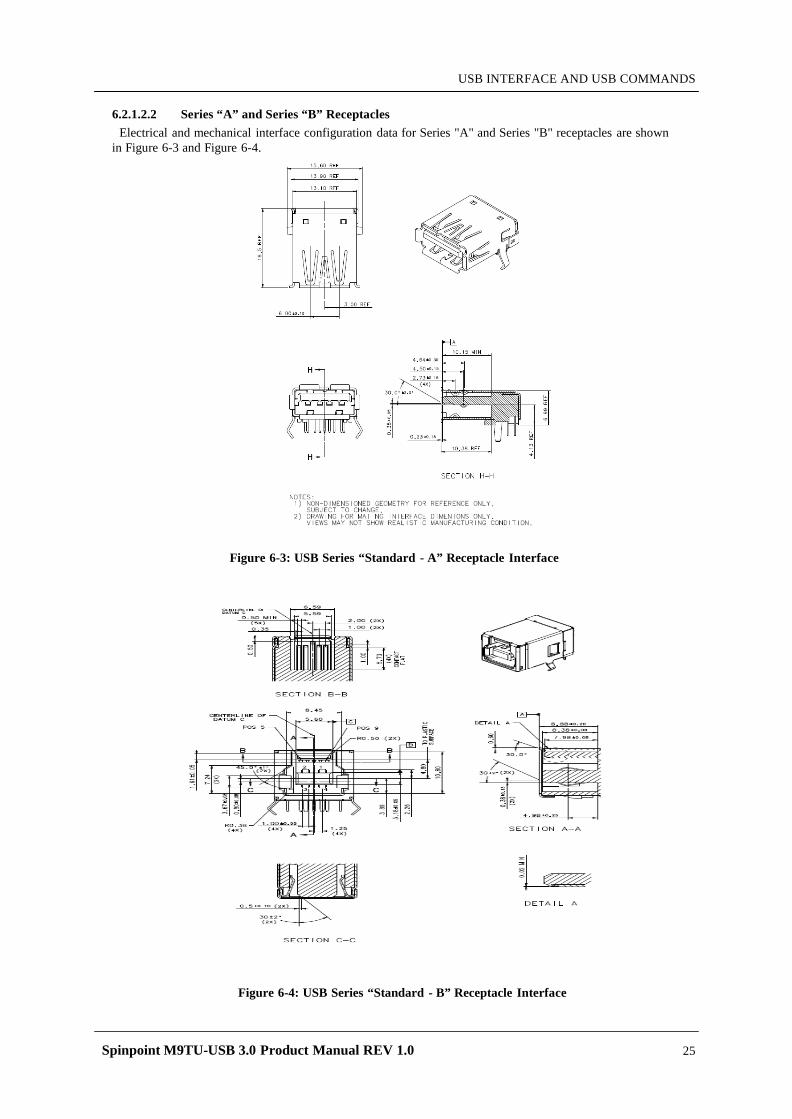
Spinpoint M9TU-USB 3.0 Product Manual REV 1.0 25
USB INTERFACE AND USB COMMANDS
6.2.1.2.2 Series “A” and Series “B” Receptacles
Electrical and mechanical interface configuration data for Series "A" and Series "B" receptacles are shown in Figure 6-3 and Figure 6-4.
Figure 6-3: USB Series “Standard - A” Receptacle Interface
Figure 6-4: USB Series “Standard - B” Receptacle Interface
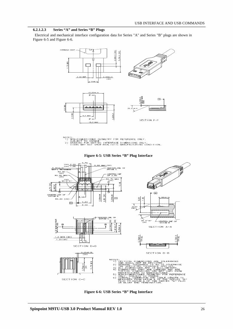
Spinpoint M9TU-USB 3.0 Product Manual REV 1.0 26
USB INTERFACE AND USB COMMANDS
6.2.1.2.3 Series “A” and Series “B” Plugs Electrical and mechanical interface configuration data for Series "A" and Series "B" plugs are shown in
Figure 6-5 and Figure 6-6.
Figure 6-5: USB Series “B” Plug Interface
Figure 6-6: USB Series “B” Plug Interface
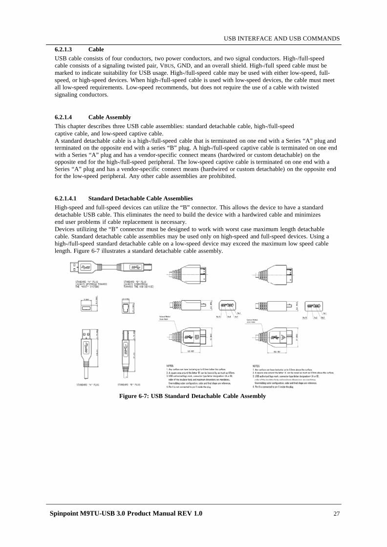
Spinpoint M9TU-USB 3.0 Product Manual REV 1.0 27
USB INTERFACE AND USB COMMANDS
6.2.1.3 Cable USB cable consists of four conductors, two power conductors, and two signal conductors. High-/full-speed cable consists of a signaling twisted pair, VBUS, GND, and an overall shield. High-/full speed cable must be marked to indicate suitability for USB usage. High-/full-speed cable may be used with either low-speed, full- speed, or high-speed devices. When high-/full-speed cable is used with low-speed devices, the cable must meet all low-speed requirements. Low-speed recommends, but does not require the use of a cable with twisted signaling conductors.
6.2.1.4 Cable Assembly This chapter describes three USB cable assemblies: standard detachable cable, high-/full-speed captive cable, and low-speed captive cable. A standard detachable cable is a high-/full-speed cable that is terminated on one end with a Series “A” plug and terminated on the opposite end with a series “B” plug. A high-/full-speed captive cable is terminated on one end with a Series “A” plug and has a vendor-specific connect means (hardwired or custom detachable) on the opposite end for the high-/full-speed peripheral. The low-speed captive cable is terminated on one end with a Series “A” plug and has a vendor-specific connect means (hardwired or custom detachable) on the opposite end for the low-speed peripheral. Any other cable assemblies are prohibited.
6.2.1.4.1 Standard Detachable Cable Assemblies High-speed and full-speed devices can utilize the “B” connector. This allows the device to have a standard detachable USB cable. This eliminates the need to build the device with a hardwired cable and minimizes end user problems if cable replacement is necessary. Devices utilizing the “B” connector must be designed to work with worst case maximum length detachable cable. Standard detachable cable assemblies may be used only on high-speed and full-speed devices. Using a high-/full-speed standard detachable cable on a low-speed device may exceed the maximum low speed cable length. Figure 6-7 illustrates a standard detachable cable assembly.
Figure 6-7: USB Standard Detachable Cable Assembly
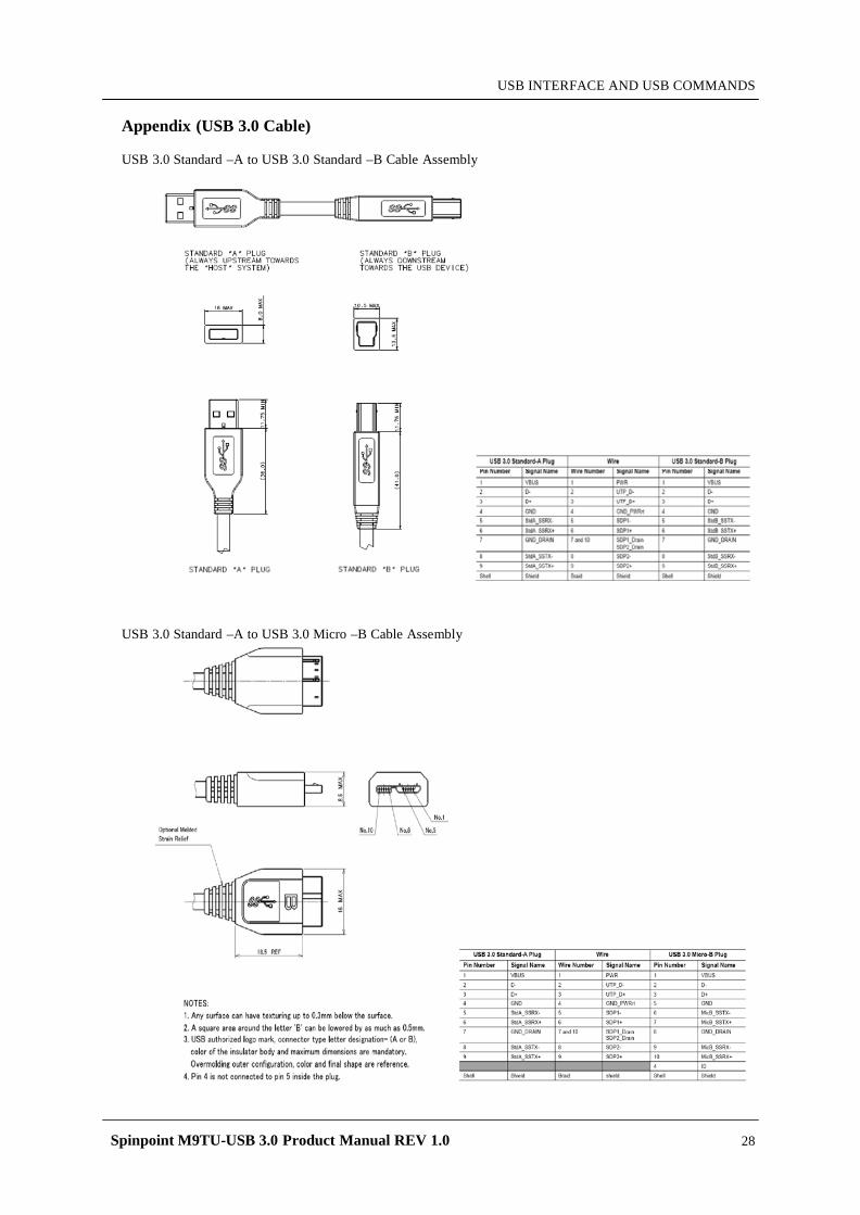
Spinpoint M9TU-USB 3.0 Product Manual REV 1.0 28
USB INTERFACE AND USB COMMANDS
Appendix (USB 3.0 Cable)
USB 3.0 Standard –A to USB 3.0 Standard –B Cable Assembly
USB 3.0 Standard –A to USB 3.0 Micro –B Cable Assembly
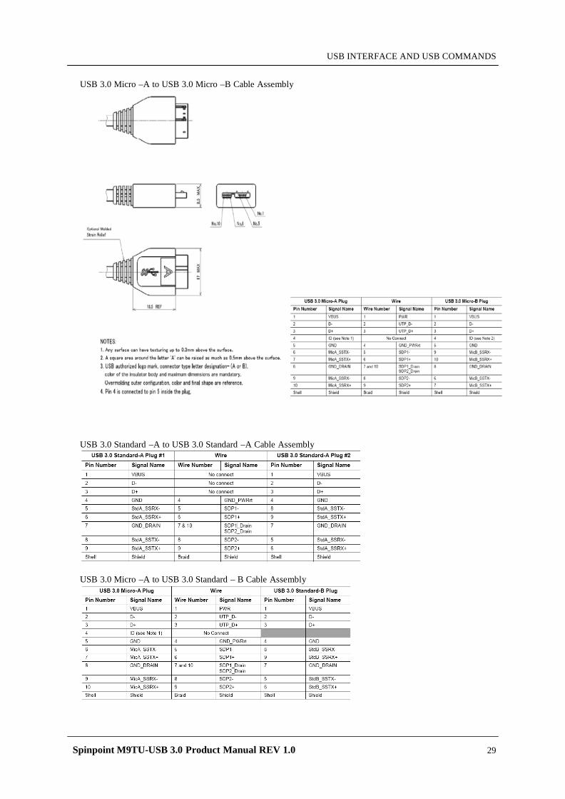
Spinpoint M9TU-USB 3.0 Product Manual REV 1.0 29
USB INTERFACE AND USB COMMANDS
USB 3.0 Micro –A to USB 3.0 Micro –B Cable Assembly
USB 3.0 Standard –A to USB 3.0 Standard –A Cable Assembly
USB 3.0 Micro –A to USB 3.0 Standard – B Cable Assembly
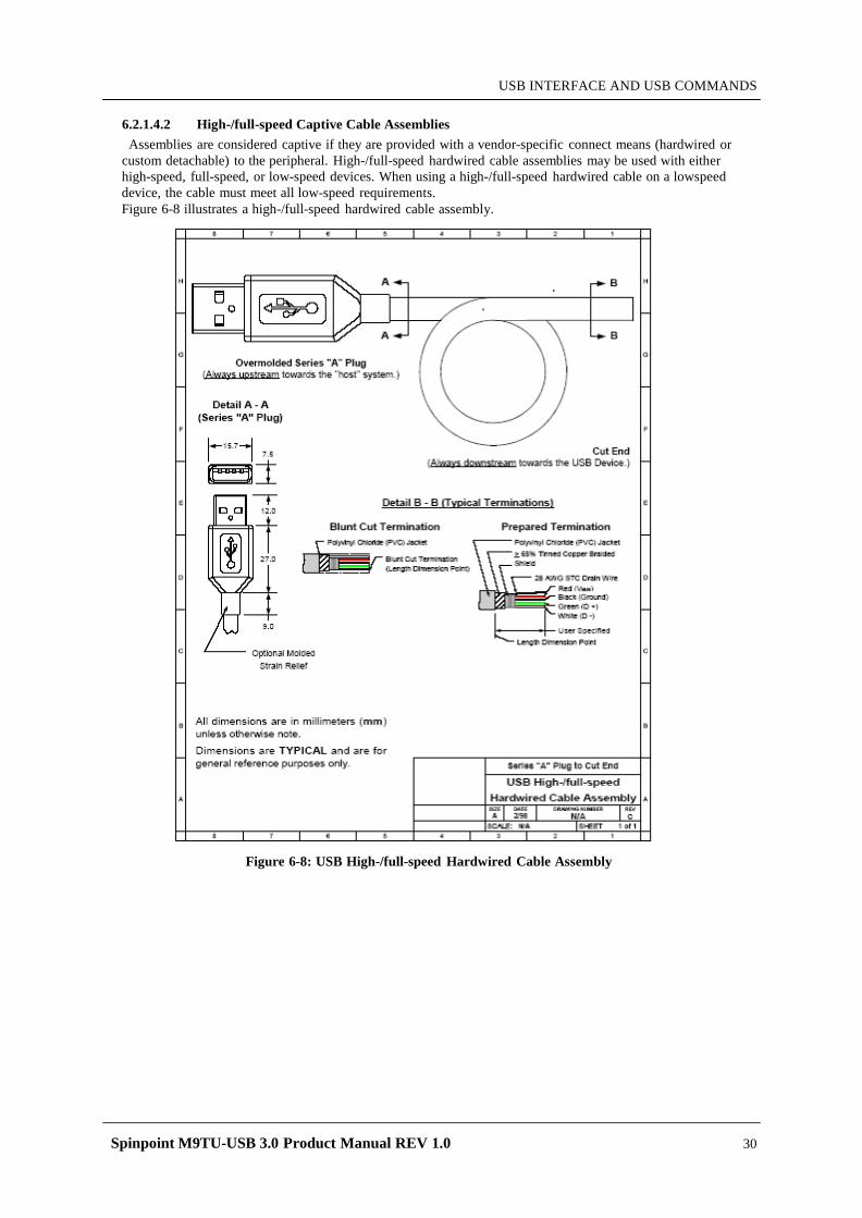
Spinpoint M9TU-USB 3.0 Product Manual REV 1.0 30
USB INTERFACE AND USB COMMANDS
6.2.1.4.2 High-/full-speed Captive Cable Assemblies Assemblies are considered captive if they are provided with a vendor-specific connect means (hardwired or
custom detachable) to the peripheral. High-/full-speed hardwired cable assemblies may be used with either high-speed, full-speed, or low-speed devices. When using a high-/full-speed hardwired cable on a lowspeed device, the cable must meet all low-speed requirements. Figure 6-8 illustrates a high-/full-speed hardwired cable assembly.
Figure 6-8: USB High-/full-speed Hardwired Cable Assembly
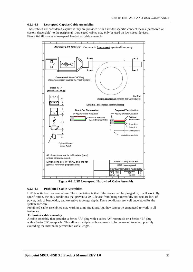
Spinpoint M9TU-USB 3.0 Product Manual REV 1.0 31
USB INTERFACE AND USB COMMANDS
6.2.1.4.3 Low-speed Captive Cable Assemblies Assemblies are considered captive if they are provided with a vendor-specific connect means (hardwired or
custom detachable) to the peripheral. Low-speed cables may only be used on low-speed devices. Figure 6-9 illustrates a low-speed hardwired cable assembly.
Figure 6-9: USB Low-speed Hardwired Cable Assembly
6.2.1.4.4 Prohibited Cable Assemblies USB is optimized for ease of use. The expectation is that if the device can be plugged in, it will work. By specification, the only conditions that prevent a USB device from being successfully utilized are lack of power, lack of bandwidth, and excessive topology depth. These conditions are well understood by the system software. Prohibited cable assemblies may work in some situations, but they cannot be guaranteed to work in all instances. Extension cable assembly A cable assembly that provides a Series “A” plug with a series “A” receptacle or a Series “B” plug with a Series “B” receptacle. This allows multiple cable segments to be connected together, possibly exceeding the maximum permissible cable length.
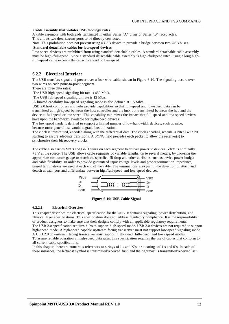
Spinpoint M9TU-USB 3.0 Product Manual REV 1.0 32
USB INTERFACE AND USB COMMANDS
Cable assembly that violates USB topology rules A cable assembly with both ends terminated in either Series “A” plugs or Series “B” receptacles. This allows two downstream ports to be directly connected. Note: This prohibition does not prevent using a USB device to provide a bridge between two USB buses. Standard detachable cables for low-speed devices Low-speed devices are prohibited from using standard detachable cables. A standard detachable cable assembly must be high-/full-speed. Since a standard detachable cable assembly is high-/fullspeed rated, using a long high-/full-speed cable exceeds the capacitive load of low-speed.
6.2.2 Electrical Interface The USB transfers signal and power over a four-wire cable, shown in Figure 6-10. The signaling occurs over two wires on each point-to-point segment. There are three data rates: The USB high-speed signaling bit rate is 480 Mb/s. The USB full-speed signaling bit rate is 12 Mb/s. A limited capability low-speed signaling mode is also defined at 1.5 Mb/s. USB 2.0 host controllers and hubs provide capabilities so that full-speed and low-speed data can be transmitted at high-speed between the host controller and the hub, but transmitted between the hub and the device at full-speed or low-speed. This capability minimizes the impact that full-speed and low-speed devices have upon the bandwidth available for high-speed devices. The low-speed mode is defined to support a limited number of low-bandwidth devices, such as mice, because more general use would degrade bus utilization. The clock is transmitted, encoded along with the differential data. The clock encoding scheme is NRZI with bit stuffing to ensure adequate transitions. A SYNC field precedes each packet to allow the receiver(s) to synchronize their bit recovery clocks.
The cable also carries VBUS and GND wires on each segment to deliver power to devices. VBUS is nominally +5 V at the source. The USB allows cable segments of variable lengths, up to several meters, by choosing the appropriate conductor gauge to match the specified IR drop and other attributes such as device power budget and cable flexibility. In order to provide guaranteed input voltage levels and proper termination impedance, biased terminations are used at each end of the cable. The terminations also permit the detection of attach and detach at each port and differentiate between high/full-speed and low-speed devices.
Figure 6-10: USB Cable Signal
6.2.2.1 Electrical Overview This chapter describes the electrical specification for the USB. It contains signaling, power distribution, and physical layer specifications. This specification does not address regulatory compliance. It is the responsibility of product designers to make sure that their designs comply with all applicable regulatory requirements. The USB 2.0 specification requires hubs to support high-speed mode. USB 2.0 devices are not required to support high-speed mode. A high-speed capable upstream facing transceiver must not support low-speed signaling mode. A USB 2.0 downstream facing transceiver must support high-speed, full-speed, and low- speed modes. To assure reliable operation at high-speed data rates, this specification requires the use of cables that conform to all current cable specifications. In this chapter, there are numerous references to strings of J’s and K’s, or to strings of 1’s and 0’s. In each of these instances, the leftmost symbol is transmitted/received first, and the rightmost is transmitted/received last.
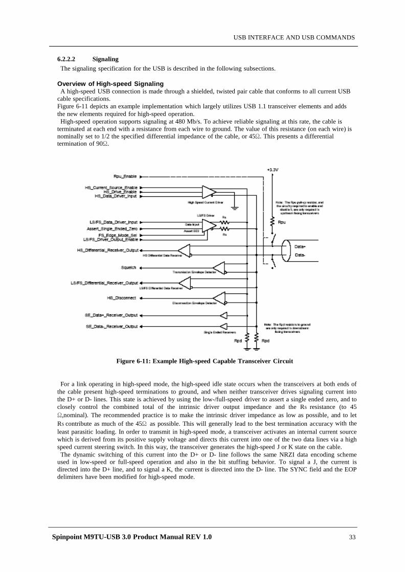
Spinpoint M9TU-USB 3.0 Product Manual REV 1.0 33
USB INTERFACE AND USB COMMANDS
6.2.2.2 Signaling The signaling specification for the USB is described in the following subsections.
Overview of High-speed Signaling A high-speed USB connection is made through a shielded, twisted pair cable that conforms to all current USB
cable specifications. Figure 6-11 depicts an example implementation which largely utilizes USB 1.1 transceiver elements and adds the new elements required for high-speed operation. High-speed operation supports signaling at 480 Mb/s. To achieve reliable signaling at this rate, the cable is
terminated at each end with a resistance from each wire to ground. The value of this resistance (on each wire) is nominally set to 1/2 the specified differential impedance of the cable, or 45Ω. This presents a differential termination of 90Ω.
Figure 6-11: Example High-speed Capable Transceiver Circuit
For a link operating in high-speed mode, the high-speed idle state occurs when the transceivers at both ends of the cable present high-speed terminations to ground, and when neither transceiver drives signaling current into the D+ or D- lines. This state is achieved by using the low-/full-speed driver to assert a single ended zero, and to closely control the combined total of the intrinsic driver output impedance and the RS resistance (to 45 Ω,nominal). The recommended practice is to make the intrinsic driver impedance as low as possible, and to let RS contribute as much of the 45Ω as possible. This will generally lead to the best termination accuracy with the least parasitic loading. In order to transmit in high-speed mode, a transceiver activates an internal current source which is derived from its positive supply voltage and directs this current into one of the two data lines via a high speed current steering switch. In this way, the transceiver generates the high-speed J or K state on the cable.
The dynamic switching of this current into the D+ or D- line follows the same NRZI data encoding scheme used in low-speed or full-speed operation and also in the bit stuffing behavior. To signal a J, the current is directed into the D+ line, and to signal a K, the current is directed into the D- line. The SYNC field and the EOP delimiters have been modified for high-speed mode.
Spinpoint M9TU-USB 3.0 Product Manual REV 1.0 34
USB INTERFACE AND USB COMMANDS
The magnitude of the current source and the value of the termination resistors are controlled to specified tolerances, and together they determine the actual voltage drive levels. The DC resistance from D+ or D- to the device ground is required to be 45Ω ±10% when measured without a load, and the differential output voltage measured across the lines (in either the J or K state) must be ±400 mV ±10% when D+ and D- are terminated with precision 45Ω resistors to ground. The differential voltage developed across the lines is used for three purposes:
-A differential receiver at the receiving end of the cable receives the differential data signal. -A differential envelope detector at the receiving end of the cable determines when the link is in the Squelch state. A receiver uses squelch detection as indication that the signal at its connector is not valid. -In the case of a downstream facing hub transceiver, a differential envelope detector monitors whether the signal at its connector is in the high-speed state. A downstream facing transceiver operating in high-speed mode is required to test for this state at a particular point in time when it is transmitting a SOF packet. This is used to detect device disconnection. In the absence of the far end terminations, the differential voltage will nominally double (as compared to when a high-speed device is present) when a high-speed J or K are continuously driven for a period exceeding the round-trip delay for the cable and board-traces between the two transceivers. USB 2.0 requires that a downstream facing transceiver must be able to operate in low-speed, full-speed, and high-speed signaling modes. An upstream facing high-speed capable transceiver must not operate in low- speed signaling mode, but must be able to operate in full-speed signaling mode. Therefore, a 1.5kΩ pull-up on the D line is not allowed for a high-speed capable device, since a high-speed capable transceiver must never signal low-speed operation to the hub port to which it is attached.
6.2.2.3 High-speed (480Mb/s) Driver Characteristics A high-speed USB connection is made through a shielded, twisted pair cable with a differential characteristic
impedance (Z0) of 90Ω ±15%, a common mode impedance (ZCM) of 30Ω ±30%, and a maximum one-way delay of 26 ns (TFSCBL). The D+ and D- circuit board traces which run between a transceiver and its associated connector should also have a nominal differential impedance of 90Ω, and together they may add an additional 4ns of delay between the transceivers. The differential output impedance of a high-speed capable driver is required to be 90Ω ±10%. When either the D+ or D- lines are driven high, VHSOH (the high-speed mode high-level output voltage driven
on a data line with a precision 45Ω load to GND) must be 400 mV ±10%. On a line which is not driven, either because the transceiver is not transmitting or because the opposite line is being driven high, VHSOL (the high speed mode low-level output voltage driven on a data line with a 45Ω load to GND) must be 0 V ±10mV.
Note: Unless indicated otherwise, all voltage measurements are to be made with respect to the local circuit ground. Note: This specification requires that a high-speed capable transceiver operating in full-speed or low-speed mode must have a driver impedance (ZHSDRV) of 45Ω ±10%. It is recommended that the driver impedances be matched to within 5Ωwithin a transceiver. For upstream facing transceivers which do not support high- speed mode, the driver output impedance (ZDRV) must fall within the range of 28Ω to 44Ω.
On downstream facing ports, RPD resistors (15 kΩ ±5%) must be connected from D+ and D- to ground. When a high-speed capable transceiver transitions to high-speed mode, the high-speed idle state is achieved by driving SE0 with the low-/full-speed drivers at each end of the link (so as to provide the required terminations), and by disconnecting the D+ pull-up resistor in the upstream facing transceiver. In the preferred embodiment, a transceiver activates its high-speed current driver only when transmitting high speed signals. This is a potential design challenge, however, since the signal amplitude and timing specifications must be met even on the first symbol within a packet. As a less efficient alternative, a transceiver may cause its high-speed current source to be continually active while in high-speed mode. When the transceiver is not transmitting, the current may be directed into the device ground rather than through the current steering switch which is used for data signaling. In CMOS implementations, the driver impedance will typically be realized by the combination of the driver’s intrinsic output impedance and RS. To optimally control ZHSDRV and to minimize parasitics, it is preferred the driver impedance be minimized (under 5Ω) and the balance of the 45Ω should be contributed by the RS component.
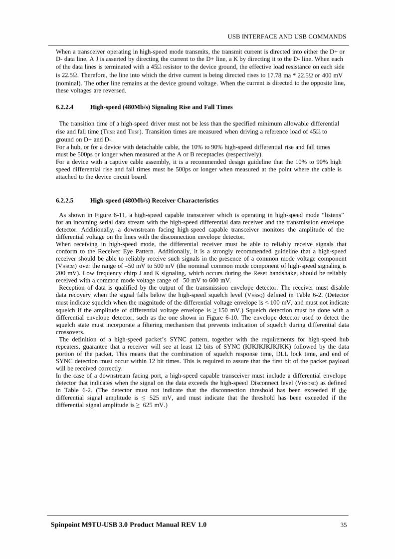
Spinpoint M9TU-USB 3.0 Product Manual REV 1.0 35
USB INTERFACE AND USB COMMANDS
When a transceiver operating in high-speed mode transmits, the transmit current is directed into either the D+ or D- data line. A J is asserted by directing the current to the D+ line, a K by directing it to the D- line. When each of the data lines is terminated with a 45Ω resistor to the device ground, the effective load resistance on each side is 22.5Ω. Therefore, the line into which the drive current is being directed rises to 17.78 ma * 22.5Ω or 400 mV (nominal). The other line remains at the device ground voltage. When the current is directed to the opposite line, these voltages are reversed.
6.2.2.4 High-speed (480Mb/s) Signaling Rise and Fall Times The transition time of a high-speed driver must not be less than the specified minimum allowable differential
rise and fall time (THSR and THSF). Transition times are measured when driving a reference load of 45Ω to ground on D+ and D-. For a hub, or for a device with detachable cable, the 10% to 90% high-speed differential rise and fall times must be 500ps or longer when measured at the A or B receptacles (respectively). For a device with a captive cable assembly, it is a recommended design guideline that the 10% to 90% high speed differential rise and fall times must be 500ps or longer when measured at the point where the cable is attached to the device circuit board.
6.2.2.5 High-speed (480Mb/s) Receiver Characteristics As shown in Figure 6-11, a high-speed capable transceiver which is operating in high-speed mode “listens”
for an incoming serial data stream with the high-speed differential data receiver and the transmission envelope detector. Additionally, a downstream facing high-speed capable transceiver monitors the amplitude of the differential voltage on the lines with the disconnection envelope detector. When receiving in high-speed mode, the differential receiver must be able to reliably receive signals that conform to the Receiver Eye Pattern. Additionally, it is a strongly recommended guideline that a high-speed receiver should be able to reliably receive such signals in the presence of a common mode voltage component (VHSCM) over the range of –50 mV to 500 mV (the nominal common mode component of high-speed signaling is 200 mV). Low frequency chirp J and K signaling, which occurs during the Reset handshake, should be reliably received with a common mode voltage range of –50 mV to 600 mV.
Reception of data is qualified by the output of the transmission envelope detector. The receiver must disable data recovery when the signal falls below the high-speed squelch level (VHSSQ) defined in Table 6-2. (Detector must indicate squelch when the magnitude of the differential voltage envelope is ≤ 100 mV, and must not indicate squelch if the amplitude of differential voltage envelope is ≥ 150 mV.) Squelch detection must be done with a differential envelope detector, such as the one shown in Figure 6-10. The envelope detector used to detect the squelch state must incorporate a filtering mechanism that prevents indication of squelch during differential data crossovers. The definition of a high-speed packet’s SYNC pattern, together with the requirements for high-speed hub
repeaters, guarantee that a receiver will see at least 12 bits of SYNC (KJKJKJKJKJKK) followed by the data portion of the packet. This means that the combination of squelch response time, DLL lock time, and end of SYNC detection must occur within 12 bit times. This is required to assure that the first bit of the packet payload will be received correctly. In the case of a downstream facing port, a high-speed capable transceiver must include a differential envelope detector that indicates when the signal on the data exceeds the high-speed Disconnect level (VHSDSC) as defined in Table 6-2. (The detector must not indicate that the disconnection threshold has been exceeded if the differential signal amplitude is ≤ 525 mV, and must indicate that the threshold has been exceeded if the differential signal amplitude is ≥ 625 mV.)
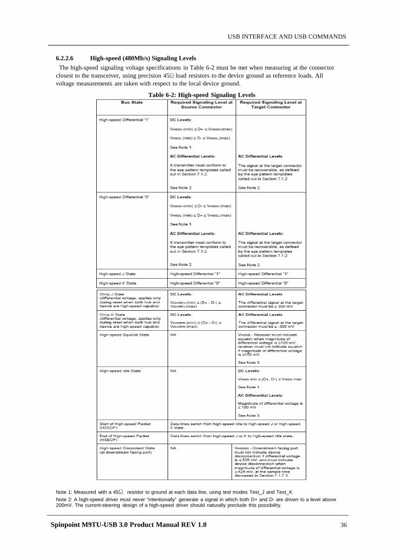
Spinpoint M9TU-USB 3.0 Product Manual REV 1.0 36
USB INTERFACE AND USB COMMANDS
6.2.2.6 High-speed (480Mb/s) Signaling Levels The high-speed signaling voltage specifications in Table 6-2 must be met when measuring at the connector
closest to the transceiver, using precision 45Ω load resistors to the device ground as reference loads. All voltage measurements are taken with respect to the local device ground.
Table 6-2: High-speed Signaling Levels
Note 1: Measured with a 45Ω resistor to ground at each data line, using test modes Test_J and Test_K Note 2: A high-speed driver must never “intentionally” generate a signal in which both D+ and D- are driven to a level above 200mV. The current-steering design of a high-speed driver should naturally preclude this possibility.
Spinpoint M9TU-USB 3.0 Product Manual REV 1.0 37
USB INTERFACE AND USB COMMANDS
6.2.3 Power Distribution This section describes the USB power distribution. Our Storage Device is Bus-powered hubs.
6.2.3.1 Overview The power source and sink requirements of different device classes can be simplified with the introduction of
the concept of a unit load. A unit load is defined to be 100 mA. The number of unit loads a device can draw is an absolute maximum, not an average over time. A device may be either low-power at one unit load or high power, consuming up to five unit loads. All devices default to low-power. The transition to high-power is under software control. It is the responsibility of software to ensure adequate power is available before allowing devices to consume high-power.
Classes of Devices The USB supports a range of power sourcing and power consuming agents; these include the following:
Root port hubs: Are directly attached to the USB Host Controller. Hub power is derived from the same source as the Host Controller. Systems that obtain operating power externally, either AC or DC, must supply at least five unit loads to each port. Such ports are called high-power ports. Battery-powered systems may supply either one or five unit loads. Ports that can supply only one unit load are termed lowpower ports. Bus-powered hubs: Draw all of their power for any internal functions and downstream facing ports from VBUS on the hub’s upstream facing port. Bus-powered hubs may only draw up to one unit load upon power-up and five unit loads after configuration. The configuration power is split between allocations to the hub, any non-removable functions and the external ports. External ports in a bus-powered hub can supply only one unit load per port regardless of the current draw on the other ports of that hub. The hub must be able to supply this port current when the hub is in the Active or Suspend state. Self-powered hubs: Power for the internal functions and downstream facing ports does not come from VBUS. However, the USB interface of the hub may draw up to one unit load from VBUS on its upstream facing port to allow the interface to function when the remainder of the hub is powered down. Hubs that obtain operating power externally (from the USB) must supply five unit loads to each port. Battery powered hubs may supply either one or five unit loads per port. Low-power bus-powered functions: All power to these devices comes from VBUS. They may draw no more than one unit load at any time. High-power bus-powered functions: All power to these devices comes from VBUS. They must draw no more than one unit load upon power-up and may draw up to five unit loads after being configured. Self-powered functions: May draw up to one unit load from VBUS to allow the USB interface to function when the remainder of the function is powered down. All other power comes from an external (to the USB) source. No device shall supply (source) current on VBUS at its upstream facing port at any time. From VBUS on its
upstream facing port, a device may only draw (sink) current. They may not provide power to the pull-up resistor on D+/D- unless VBUS is present. When VBUS is removed, the device must remove power from the D+/D- pull-up resistor within 10 seconds. On power-up, a device needs to ensure that its upstream facing port is not driving the bus, so that the device is able to receive the reset signaling. Devices must also ensure that the maximum operating current drawn by a device is one unit load, until configured. Any device that draws power from the bus must be able to detect lack of activity on the bus, enter the Suspend state, and reduce its current consumption from VBUS.
6.2.3.2 Bus-powered Hubs Bus-powered hub power requirements can be met with a power control circuit such as the one shown in Figure
6-12. Bus-powered hubs often contain at least one non-removable function. Power is always available to the hub’s controller, which permits host access to power management and other configuration registers during the enumeration process. A non-removable function(s) may require that its power be switched, so that upon power-up, the entire device (hub and non-removable functions) draws no more than one unit load.
Power switching on any non-removable function may be implemented either by removing its power or by shutting off the clock. Switching on the non-removable function is not required if the aggregate power drawn by it and the Hub Controller is less than one unit load. However, as long as the hub port associated with the function is in the Power-off state, the function must be logically reset and the device must appear to be not connected. The total current drawn by a bus-powered device is the sum of the current to the Hub Controller, any non-removable function(s), and the downstream facing ports.
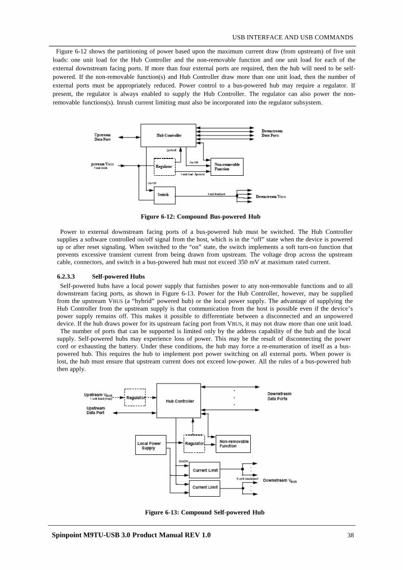
Spinpoint M9TU-USB 3.0 Product Manual REV 1.0 38
USB INTERFACE AND USB COMMANDS
Figure 6-12 shows the partitioning of power based upon the maximum current draw (from upstream) of five unit loads: one unit load for the Hub Controller and the non-removable function and one unit load for each of the external downstream facing ports. If more than four external ports are required, then the hub will need to be self-powered. If the non-removable function(s) and Hub Controller draw more than one unit load, then the number of external ports must be appropriately reduced. Power control to a bus-powered hub may require a regulator. If present, the regulator is always enabled to supply the Hub Controller. The regulator can also power the non-removable functions(s). Inrush current limiting must also be incorporated into the regulator subsystem.
Figure 6-12: Compound Bus-powered Hub
Power to external downstream facing ports of a bus-powered hub must be switched. The Hub Controller supplies a software controlled on/off signal from the host, which is in the “off” state when the device is powered up or after reset signaling. When switched to the “on” state, the switch implements a soft turn-on function that prevents excessive transient current from being drawn from upstream. The voltage drop across the upstream cable, connectors, and switch in a bus-powered hub must not exceed 350 mV at maximum rated current.
6.2.3.3 Self-powered Hubs Self-powered hubs have a local power supply that furnishes power to any non-removable functions and to all
downstream facing ports, as shown in Figure 6-13. Power for the Hub Controller, however, may be supplied from the upstream VBUS (a “hybrid” powered hub) or the local power supply. The advantage of supplying the Hub Controller from the upstream supply is that communication from the host is possible even if the device’s power supply remains off. This makes it possible to differentiate between a disconnected and an unpowered device. If the hub draws power for its upstream facing port from VBUS, it may not draw more than one unit load. The number of ports that can be supported is limited only by the address capability of the hub and the local
supply. Self-powered hubs may experience loss of power. This may be the result of disconnecting the power cord or exhausting the battery. Under these conditions, the hub may force a re-enumeration of itself as a bus- powered hub. This requires the hub to implement port power switching on all external ports. When power is lost, the hub must ensure that upstream current does not exceed low-power. All the rules of a bus-powered hub then apply.
Figure 6-13: Compound Self-powered Hub
Spinpoint M9TU-USB 3.0 Product Manual REV 1.0 39
USB INTERFACE AND USB COMMANDS
6.3 Protocol Layer This chapter presents a bottom-up view of the USB protocol, starting with field and packet definitions. This is followed by a description of packet transaction formats for different transaction types. Link layer flow control and transaction level fault recovery are then covered. The chapter finishes with a discussion of retry synchronization, babble, loss of bus activity recovery, and high-speed PING protocol.
6.3.1 Protocol Layer Overview This chapter describes the USB packets at a byte level including the sync, pid, address, endpoint, CRC fields. Once this has been grasped it moves on to the next protocol layer, USB packets. Unlike RS-232 or similar serial interfaces where the format of data being sent is not defined, USB is made up of several layers of protocols. While this sounds complicated, don’t give up now. Once you understand what is going on, you really only have to worry about the higher level layers. In fact most USB controller I.C.s will take care of the lower layer, thus making it almost invisible to the end designer.
Each USB transaction consists of a • Token Packet (Header defining what it expects to follow), an • Optional Data Packet, (Containing the payload) and a • Status Packet (Used to acknowledge transactions and to provide a means of error correction)
As we have already discussed, USB is a host centric bus. The host initiates all transactions. The first packet, also called a token is generated by the host to describe what is to follow and whether the data transaction will be a read or write and what the device’s address and designated endpoint is. The next packet is generally a data packet carrying the payload and is followed by a handshaking packet, reporting if the data or token was received successfully, or if the endpoint is stalled or not available to accept data.
Frame = SOF + Transaction + Transaction + Transaction Transaction = Setup Packet + Data Packet + Handshake Packet
Byte/Bit Ordering Bits are sent out onto the bus least-significant bit (LSb) first, followed by the next LSb, through to the mostsignificant bit (MSb) last. In the following diagrams, packets are displayed such that both individual bits and fields are represented (in a left to right reading order) as they would move across the bus. Multiple byte fields in standard descriptors, requests, and responses are interpreted as and moved over the bus in little-endian order, i.e., LSB to MSB.
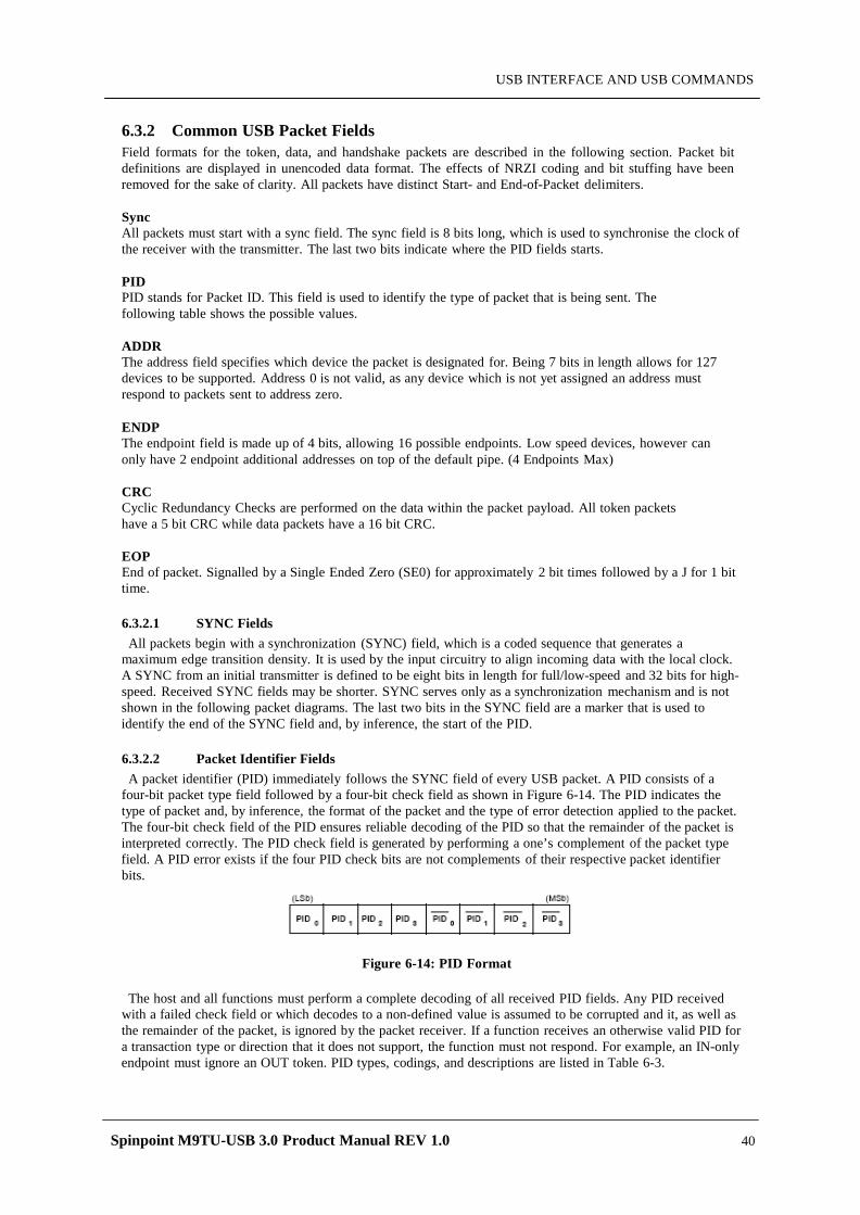
Spinpoint M9TU-USB 3.0 Product Manual REV 1.0 40
USB INTERFACE AND USB COMMANDS
6.3.2 Common USB Packet Fields Field formats for the token, data, and handshake packets are described in the following section. Packet bit definitions are displayed in unencoded data format. The effects of NRZI coding and bit stuffing have been removed for the sake of clarity. All packets have distinct Start- and End-of-Packet delimiters.
Sync All packets must start with a sync field. The sync field is 8 bits long, which is used to synchronise the clock of the receiver with the transmitter. The last two bits indicate where the PID fields starts.
PID PID stands for Packet ID. This field is used to identify the type of packet that is being sent. The following table shows the possible values.
ADDR The address field specifies which device the packet is designated for. Being 7 bits in length allows for 127 devices to be supported. Address 0 is not valid, as any device which is not yet assigned an address must respond to packets sent to address zero.
ENDP The endpoint field is made up of 4 bits, allowing 16 possible endpoints. Low speed devices, however can only have 2 endpoint additional addresses on top of the default pipe. (4 Endpoints Max)
CRC Cyclic Redundancy Checks are performed on the data within the packet payload. All token packets have a 5 bit CRC while data packets have a 16 bit CRC.
EOP End of packet. Signalled by a Single Ended Zero (SE0) for approximately 2 bit times followed by a J for 1 bit time.
6.3.2.1 SYNC Fields All packets begin with a synchronization (SYNC) field, which is a coded sequence that generates a
maximum edge transition density. It is used by the input circuitry to align incoming data with the local clock. A SYNC from an initial transmitter is defined to be eight bits in length for full/low-speed and 32 bits for high-speed. Received SYNC fields may be shorter. SYNC serves only as a synchronization mechanism and is not shown in the following packet diagrams. The last two bits in the SYNC field are a marker that is used to identify the end of the SYNC field and, by inference, the start of the PID.
6.3.2.2 Packet Identifier Fields A packet identifier (PID) immediately follows the SYNC field of every USB packet. A PID consists of a
four-bit packet type field followed by a four-bit check field as shown in Figure 6-14. The PID indicates the type of packet and, by inference, the format of the packet and the type of error detection applied to the packet. The four-bit check field of the PID ensures reliable decoding of the PID so that the remainder of the packet is interpreted correctly. The PID check field is generated by performing a one’s complement of the packet type field. A PID error exists if the four PID check bits are not complements of their respective packet identifier bits.
Figure 6-14: PID Format
The host and all functions must perform a complete decoding of all received PID fields. Any PID received with a failed check field or which decodes to a non-defined value is assumed to be corrupted and it, as well as the remainder of the packet, is ignored by the packet receiver. If a function receives an otherwise valid PID for a transaction type or direction that it does not support, the function must not respond. For example, an IN-only endpoint must ignore an OUT token. PID types, codings, and descriptions are listed in Table 6-3.
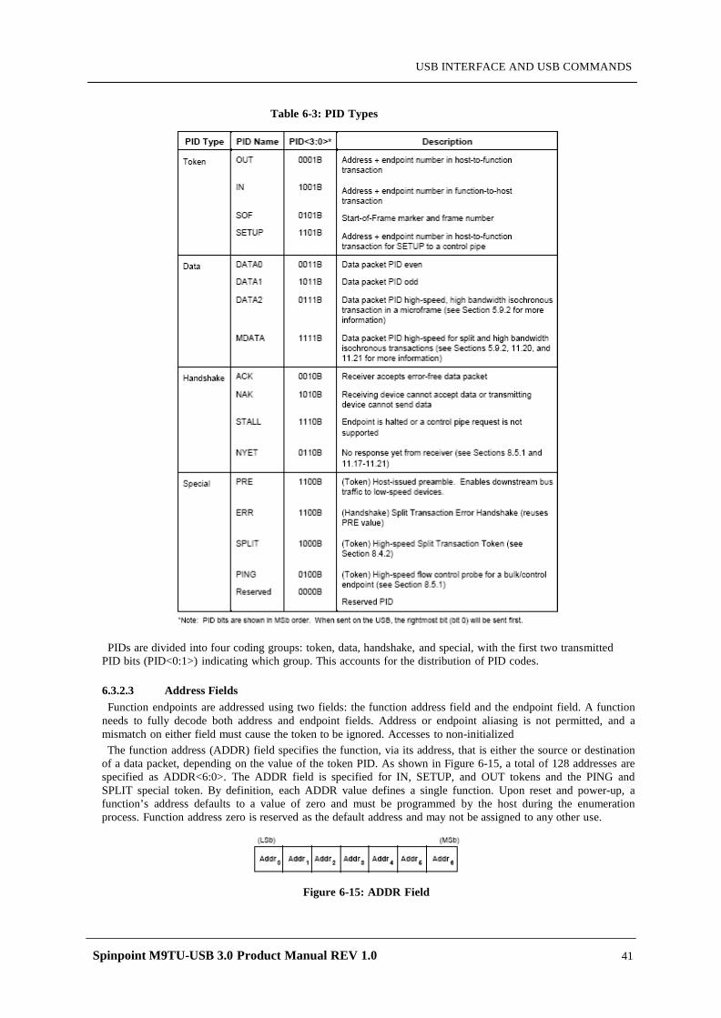
Spinpoint M9TU-USB 3.0 Product Manual REV 1.0 41
USB INTERFACE AND USB COMMANDS
Table 6-3: PID Types
PIDs are divided into four coding groups: token, data, handshake, and special, with the first two transmitted PID bits (PID<0:1>) indicating which group. This accounts for the distribution of PID codes.
6.3.2.3 Address Fields Function endpoints are addressed using two fields: the function address field and the endpoint field. A function
needs to fully decode both address and endpoint fields. Address or endpoint aliasing is not permitted, and a mismatch on either field must cause the token to be ignored. Accesses to non-initialized The function address (ADDR) field specifies the function, via its address, that is either the source or destination
of a data packet, depending on the value of the token PID. As shown in Figure 6-15, a total of 128 addresses are specified as ADDR<6:0>. The ADDR field is specified for IN, SETUP, and OUT tokens and the PING and SPLIT special token. By definition, each ADDR value defines a single function. Upon reset and power-up, a function’s address defaults to a value of zero and must be programmed by the host during the enumeration process. Function address zero is reserved as the default address and may not be assigned to any other use.
Figure 6-15: ADDR Field
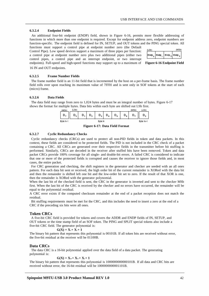
Spinpoint M9TU-USB 3.0 Product Manual REV 1.0 42
USB INTERFACE AND USB COMMANDS
6.3.2.4 Endpoint Fields
An additional four-bit endpoint (ENDP) field, shown in Figure 6-16, permits more flexible addressing of functions in which more than one endpoint is required. Except for endpoint address zero, endpoint numbers are function-specific. The endpoint field is defined for IN, SETUP, and OUT tokens and the PING special token. All functions must support a control pipe at endpoint number zero (the Default Control Pipe). Low speed devices support a maximum of three pipes per function: a control pipe at endpoint number zero plus two additional pipes (either two control pipes, a control pipe and an interrupt endpoint, or two interrupt endpoints). Full-speed and high-speed functions may support up to a maximum of 16 IN and OUT endpoints.
6.3.2.5 Frame Number Fields The frame number field is an 11-bit field that is incremented by the host on a per-frame basis. The frame number
field rolls over upon reaching its maximum value of 7FFH and is sent only in SOF tokens at the start of each (micro) frame.
6.3.2.6 Data Fields The data field may range from zero to 1,024 bytes and must be an integral number of bytes. Figure 6-17
shows the format for multiple bytes. Data bits within each byte are shifted out LSb first.
Figure 6-17: Data Field Format
6.3.2.7 Cyclic Redundancy Checks Cyclic redundancy checks (CRCs) are used to protect all non-PID fields in token and data packets. In this
context, these fields are considered to be protected fields. The PID is not included in the CRC check of a packet containing a CRC. All CRCs are generated over their respective fields in the transmitter before bit stuffing is performed. Similarly, CRCs are decoded in the receiver after stuffed bits have been removed. Token and data packet CRCs provide 100% coverage for all single- and double-bit errors. A failed CRC is considered to indicate that one or more of the protected fields is corrupted and causes the receiver to ignore those fields and, in most cases, the entire packet. For CRC generation and checking, the shift registers in the generator and checker are seeded with an all ones
pattern. For each data bit sent or received, the high order bit of the current remainder is XORed with the data bit and then the remainder is shifted left one bit and the low-order bit set to zero. If the result of that XOR is one, then the remainder is XORed with the generator polynomial. When the last bit of the checked field is sent, the CRC in the generator is inverted and sent to the checker MSb first. When the last bit of the CRC is received by the checker and no errors have occurred, the remainder will be equal to the polynomial residual. A CRC error exists if the computed checksum remainder at the end of a packet reception does not match the residual. Bit stuffing requirements must be met for the CRC, and this includes the need to insert a zero at the end of a
CRC if the preceding six bits were all ones.
Token CRCs A five-bit CRC field is provided for tokens and covers the ADDR and ENDP fields of IN, SETUP, and
OUT tokens or the time stamp field of an SOF token. The PING and SPLIT special tokens also include a five-bit CRC field. The generator polynomial is:
G(X) = X5 + X2 + 1 The binary bit pattern that represents this polynomial is 00101B. If all token bits are received without error, the five-bit residual at the receiver will be 01100B.
Data CRCs The data CRC is a 16-bit polynomial applied over the data field of a data packet. The generating
polynomial is: G(X) = X16 + X15 + X2 + 1
The binary bit pattern that represents this polynomial is 1000000000000101B. If all data and CRC bits are received without error, the 16-bit residual will be 1000000000001101B.
Figure 6-16 Endpoint Field
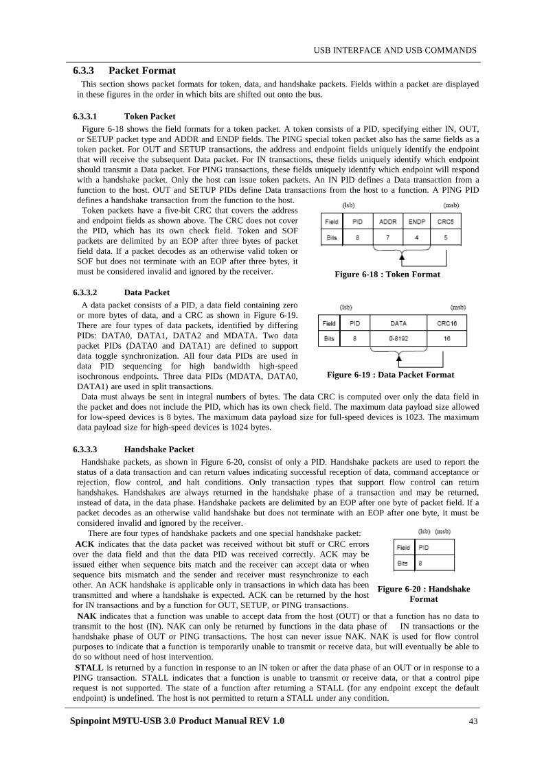
Spinpoint M9TU-USB 3.0 Product Manual REV 1.0 43
USB INTERFACE AND USB COMMANDS
6.3.3 Packet Format This section shows packet formats for token, data, and handshake packets. Fields within a packet are displayed
in these figures in the order in which bits are shifted out onto the bus. 6.3.3.1 Token Packet
Figure 6-18 shows the field formats for a token packet. A token consists of a PID, specifying either IN, OUT, or SETUP packet type and ADDR and ENDP fields. The PING special token packet also has the same fields as a token packet. For OUT and SETUP transactions, the address and endpoint fields uniquely identify the endpoint that will receive the subsequent Data packet. For IN transactions, these fields uniquely identify which endpoint should transmit a Data packet. For PING transactions, these fields uniquely identify which endpoint will respond with a handshake packet. Only the host can issue token packets. An IN PID defines a Data transaction from a function to the host. OUT and SETUP PIDs define Data transactions from the host to a function. A PING PID defines a handshake transaction from the function to the host.
Token packets have a five-bit CRC that covers the address and endpoint fields as shown above. The CRC does not cover the PID, which has its own check field. Token and SOF packets are delimited by an EOP after three bytes of packet field data. If a packet decodes as an otherwise valid token or SOF but does not terminate with an EOP after three bytes, it must be considered invalid and ignored by the receiver.
6.3.3.2 Data Packet
A data packet consists of a PID, a data field containing zero or more bytes of data, and a CRC as shown in Figure 6-19. There are four types of data packets, identified by differing PIDs: DATA0, DATA1, DATA2 and MDATA. Two data packet PIDs (DATA0 and DATA1) are defined to support data toggle synchronization. All four data PIDs are used in data PID sequencing for high bandwidth high-speed isochronous endpoints. Three data PIDs (MDATA, DATA0, DATA1) are used in split transactions. Data must always be sent in integral numbers of bytes. The data CRC is computed over only the data field in
the packet and does not include the PID, which has its own check field. The maximum data payload size allowed for low-speed devices is 8 bytes. The maximum data payload size for full-speed devices is 1023. The maximum data payload size for high-speed devices is 1024 bytes.
6.3.3.3 Handshake Packet
Handshake packets, as shown in Figure 6-20, consist of only a PID. Handshake packets are used to report the status of a data transaction and can return values indicating successful reception of data, command acceptance or rejection, flow control, and halt conditions. Only transaction types that support flow control can return handshakes. Handshakes are always returned in the handshake phase of a transaction and may be returned, instead of data, in the data phase. Handshake packets are delimited by an EOP after one byte of packet field. If a packet decodes as an otherwise valid handshake but does not terminate with an EOP after one byte, it must be considered invalid and ignored by the receiver.
There are four types of handshake packets and one special handshake packet: ACK indicates that the data packet was received without bit stuff or CRC errors over the data field and that the data PID was received correctly. ACK may be issued either when sequence bits match and the receiver can accept data or when sequence bits mismatch and the sender and receiver must resynchronize to each other. An ACK handshake is applicable only in transactions in which data has been transmitted and where a handshake is expected. ACK can be returned by the host for IN transactions and by a function for OUT, SETUP, or PING transactions. NAK indicates that a function was unable to accept data from the host (OUT) or that a function has no data to transmit to the host (IN). NAK can only be returned by functions in the data phase of IN transactions or the handshake phase of OUT or PING transactions. The host can never issue NAK. NAK is used for flow control purposes to indicate that a function is temporarily unable to transmit or receive data, but will eventually be able to do so without need of host intervention. STALL is returned by a function in response to an IN token or after the data phase of an OUT or in response to a PING transaction. STALL indicates that a function is unable to transmit or receive data, or that a control pipe request is not supported. The state of a function after returning a STALL (for any endpoint except the default endpoint) is undefined. The host is not permitted to return a STALL under any condition.
Figure 6-19 : Data Packet Format
Figure 6-18 : Token Format
Figure 6-20 : Handshake Format
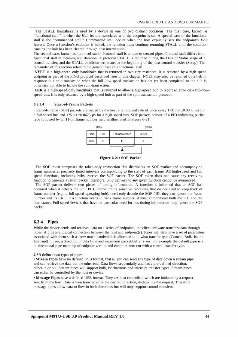
Spinpoint M9TU-USB 3.0 Product Manual REV 1.0 44
USB INTERFACE AND USB COMMANDS
The STALL handshake is used by a device in one of two distinct occasions. The first case, known as “functional stall,” is when the Halt feature associated with the endpoint is set. A special case of the functional stall is the “commanded stall.” Commanded stall occurs when the host explicitly sets the endpoint’s Halt feature. Once a function’s endpoint is halted, the function must continue returning STALL until the condition causing the halt has been cleared through host intervention. The second case, known as “protocol stall,” Protocol stall is unique to control pipes. Protocol stall differs from functional stall in meaning and duration. A protocol STALL is returned during the Data or Status stage of a control transfer, and the STALL condition terminates at the beginning of the next control transfer (Setup). The remainder of this section refers to the general case of a functional stall. NYET is a high-speed only handshake that is returned in two circumstances. It is returned by a high speed endpoint as part of the PING protocol described later in this chapter. NYET may also be returned by a hub in response to a split-transaction when the full-/low-speed transaction has not yet been completed or the hub is otherwise not able to handle the split-transaction. ERR is a high-speed only handshake that is returned to allow a high-speed hub to report an error on a full-/low-speed bus. It is only returned by a high-speed hub as part of the split transaction protocol.
6.3.3.4 Start-of-Frame Packets Start-of-Frame (SOF) packets are issued by the host at a nominal rate of once every 1.00 ms ±0.0005 ms for
a full-speed bus and 125 µs ±0.0625 µs for a high-speed bus. SOF packets consist of a PID indicating packet type followed by an 11-bit frame number field as illustrated in Figure 6-21.
Figure 6-21: SOF Packet
The SOF token comprises the token-only transaction that distributes an SOF marker and accompanying
frame number at precisely timed intervals corresponding to the start of each frame. All high-speed and full speed functions, including hubs, receive the SOF packet. The SOF token does not cause any receiving function to generate a return packet; therefore, SOF delivery to any given function cannot be guaranteed. The SOF packet delivers two pieces of timing information. A function is informed that an SOF has
occurred when it detects the SOF PID. Frame timing sensitive functions, that do not need to keep track of frame number (e.g., a full-speed operating hub), need only decode the SOF PID; they can ignore the frame number and its CRC. If a function needs to track frame number, it must comprehend both the PID and the time stamp. Full-speed devices that have no particular need for bus timing information may ignore the SOF packet.
6.3.4 Pipes While the device sends and receives data on a series of endpoints, the client software transfers data through pipes. A pipe is a logical connection between the host and endpoint(s). Pipes will also have a set of parameters associated with them such as how much bandwidth is allocated to it, what transfer type (Control, Bulk, Iso or Interrupt) it uses, a direction of data flow and maximum packet/buffer sizes. For example the default pipe is a bi-directional pipe made up of endpoint zero in and endpoint zero out with a control transfer type.
USB defines two types of pipes • Stream Pipes have no defined USB format, that is, you can send any type of data down a stream pipe and can retrieve the data out the other end. Data flows sequentially and has a pre-defined direction, either in or out. Stream pipes will support bulk, isochronous and interrupt transfer types. Stream pipes can either be controlled by the host or device. • Message Pipes have a defined USB format. They are host controlled, which are initiated by a request sent from the host. Data is then transferred in the desired direction, dictated by the request. Therefore message pipes allow data to flow in both directions but will only support control transfers.
Spinpoint M9TU-USB 3.0 Product Manual REV 1.0 45
USB INTERFACE AND USB COMMANDS
6.3.5 Transfer/Endpoint Types The Universal Serial Bus specification defines four transfer/endpoint types, • Control Transfers • Interrupt Transfers • Isochronous Transfers • Bulk Transfers
Control Transfer - Packet Length: 8bytes (Low), 8, 16, 32 or 64bytes (High), 64bytes (Full) - Stage
- SetUp Stage: SETUP->DATA 0->ACK Packet - Optional Data Stage: IN (Data transmit), OUT (Control need) Packet - Status Stage: IN/OUT packet for reports the status of the overall
- Command/Status Operation. ex) Device Setup data transfer
Interrupt Transfer - Guaranteed Latency - Stream Pipe - Unidirectional - Error detection and next period retry - Maximum data payload size: 8bytes (Low), 64bytes (Full), 1024bytes (High) ex) Mouse, JoyStick, Keyboard
Isochronous Transfer - Guaranteed access to USB bandwidth - Bounded latency - Stream Pipe - Unidirectional - Error detection via CRC, but no retry or guarantee of delivery - Full & high speed modes only - No data toggling - Maximum data payload size: 1023bytes (Full), 1024bytes (High) ex) Audio, Telephone
Bulk Transfer - Used to transfer large bursty data - Error detection via CRC, with guarantee of delivery - No guarantee of bandwidth or minimum latency - Stream Pipe - Unidirectional - Full & high speed modes only - Maximum bulk packet size - 8, 16, 32 or 64bytes (Full), up to 512bytes (High) - Large Data Operation ex) Print, Scanner, Still Camera
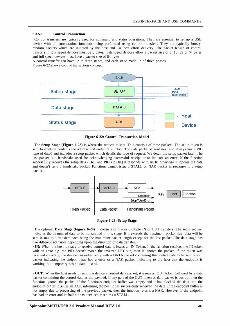
Spinpoint M9TU-USB 3.0 Product Manual REV 1.0 46
USB INTERFACE AND USB COMMANDS
6.3.5.1 Control Transaction Control transfers are typically used for command and status operations. They are essential to set up a USB
device with all enumeration functions being performed using control transfers. They are typically bursty, random packets which are initiated by the host and use best effort delivery. The packet length of control transfers in low speed devices must be 8 bytes, high speed devices allow a packet size of 8, 16, 32 or 64 bytes and full speed devices must have a packet size of 64 bytes. A control transfer can have up to three stages, and each stage made up of three phases. Figure 6-22 shows control transaction concept.
Figure 6-22: Control Transaction Model
The Setup Stage (Figure 6-23) is where the request is sent. This consists of three packets. The setup token is sent first which contains the address and endpoint number. The data packet is sent next and always has a PID type of data0 and includes a setup packet which details the type of request. We detail the setup packet later. The last packet is a handshake used for acknowledging successful receipt or to indicate an error. If the function successfully receives the setup data (CRC and PID etc OK) it responds with ACK, otherwise it ignores the data and doesn’t send a handshake packet. Functions cannot issue a STALL or NAK packet in response to a setup packet.
Figure 6-23: Setup Stage
The optional Data Stage (Figure 6-24) consists of one or multiple IN or OUT transfers. The setup request indicates the amount of data to be transmitted in this stage. If it exceeds the maximum packet size, data will be sent in multiple transfers each being the maximum packet length except for the last packet. The data stage has two different scenarios depending upon the direction of data transfer. • IN: When the host is ready to receive control data it issues an IN Token. If the function receives the IN token with an error e.g. the PID doesn't match the inverted PID bits, then it ignores the packet. If the token was received correctly, the device can either reply with a DATA packet containing the control data to be sent, a stall packet indicating the endpoint has had a error or a NAK packet indicating to the host that the endpoint is working, but temporary has no data to send. • OUT: When the host needs to send the device a control data packet, it issues an OUT token followed by a data packet containing the control data as the payload. If any part of the OUT token or data packet is corrupt then the function ignores the packet. If the function's endpoint buffer was empty and it has clocked the data into the endpoint buffer it issues an ACK informing the host it has successfully received the data. If the endpoint buffer is not empty due to processing of the previous packet, then the function returns a NAK. However if the endpoint has had an error and its halt bit has been set, it returns a STALL.
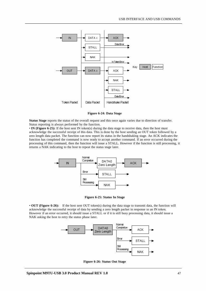
Spinpoint M9TU-USB 3.0 Product Manual REV 1.0 47
USB INTERFACE AND USB COMMANDS
Figure 6-24: Data Stage
Status Stage reports the status of the overall request and this once again varies due to direction of transfer. Status reporting is always performed by the function. • IN (Figure 6-25): If the host sent IN token(s) during the data stage to receive data, then the host must acknowledge the successful receipt of this data. This is done by the host sending an OUT token followed by a zero length data packet. The function can now report its status in the handshaking stage. An ACK indicates the function has completed the command is now ready to accept another command. If an error occurred during the processing of this command, then the function will issue a STALL. However if the function is still processing, it returns a NAK indicating to the host to repeat the status stage later.
Figure 6-25: Status In Stage
• OUT (Figure 6-26): If the host sent OUT token(s) during the data stage to transmit data, the function will acknowledge the successful receipt of data by sending a zero length packet in response to an IN token. However if an error occurred, it should issue a STALL or if it is still busy processing data, it should issue a NAK asking the host to retry the status phase later.
Figure 6-26: Status Out Stage
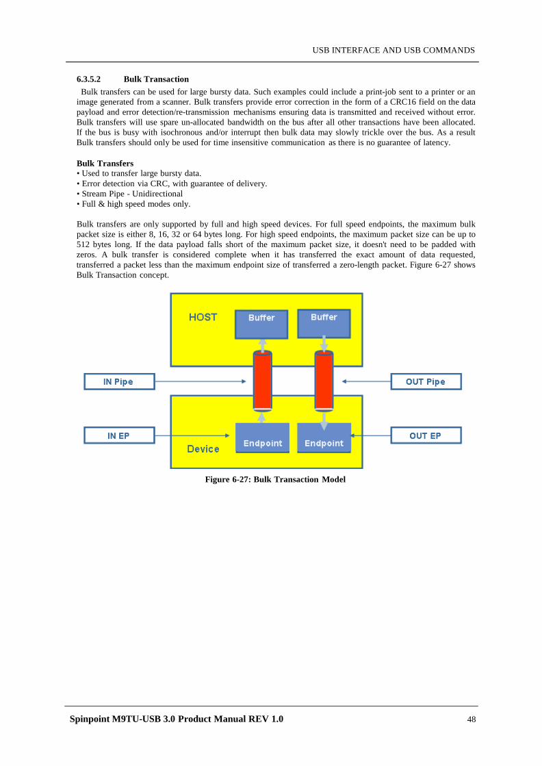
Spinpoint M9TU-USB 3.0 Product Manual REV 1.0 48
USB INTERFACE AND USB COMMANDS
6.3.5.2 Bulk Transaction Bulk transfers can be used for large bursty data. Such examples could include a print-job sent to a printer or an
image generated from a scanner. Bulk transfers provide error correction in the form of a CRC16 field on the data payload and error detection/re-transmission mechanisms ensuring data is transmitted and received without error. Bulk transfers will use spare un-allocated bandwidth on the bus after all other transactions have been allocated. If the bus is busy with isochronous and/or interrupt then bulk data may slowly trickle over the bus. As a result Bulk transfers should only be used for time insensitive communication as there is no guarantee of latency.
Bulk Transfers • Used to transfer large bursty data. • Error detection via CRC, with guarantee of delivery. • Stream Pipe - Unidirectional • Full & high speed modes only.
Bulk transfers are only supported by full and high speed devices. For full speed endpoints, the maximum bulk packet size is either 8, 16, 32 or 64 bytes long. For high speed endpoints, the maximum packet size can be up to 512 bytes long. If the data payload falls short of the maximum packet size, it doesn't need to be padded with zeros. A bulk transfer is considered complete when it has transferred the exact amount of data requested, transferred a packet less than the maximum endpoint size of transferred a zero-length packet. Figure 6-27 shows Bulk Transaction concept.
Figure 6-27: Bulk Transaction Model
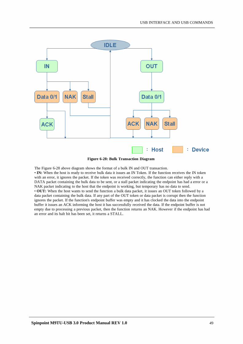
Spinpoint M9TU-USB 3.0 Product Manual REV 1.0 49
USB INTERFACE AND USB COMMANDS
Figure 6-28: Bulk Transaction Diagram
The Figure 6-28 above diagram shows the format of a bulk IN and OUT transaction. • IN: When the host is ready to receive bulk data it issues an IN Token. If the function receives the IN token with an error, it ignores the packet. If the token was received correctly, the function can either reply with a DATA packet containing the bulk data to be sent, or a stall packet indicating the endpoint has had a error or a NAK packet indicating to the host that the endpoint is working, but temporary has no data to send. • OUT: When the host wants to send the function a bulk data packet, it issues an OUT token followed by a data packet containing the bulk data. If any part of the OUT token or data packet is corrupt then the function ignores the packet. If the function's endpoint buffer was empty and it has clocked the data into the endpoint buffer it issues an ACK informing the host it has successfully received the data. If the endpoint buffer is not empty due to processing a previous packet, then the function returns an NAK. However if the endpoint has had an error and its halt bit has been set, it returns a STALL.
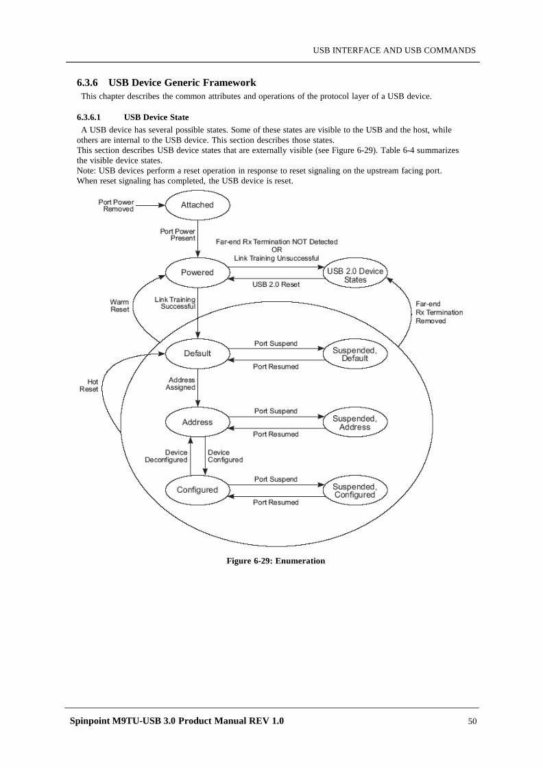
Spinpoint M9TU-USB 3.0 Product Manual REV 1.0 50
USB INTERFACE AND USB COMMANDS
6.3.6 USB Device Generic Framework This chapter describes the common attributes and operations of the protocol layer of a USB device.
6.3.6.1 USB Device State A USB device has several possible states. Some of these states are visible to the USB and the host, while
others are internal to the USB device. This section describes those states. This section describes USB device states that are externally visible (see Figure 6-29). Table 6-4 summarizes the visible device states. Note: USB devices perform a reset operation in response to reset signaling on the upstream facing port. When reset signaling has completed, the USB device is reset.
Figure 6-29: Enumeration
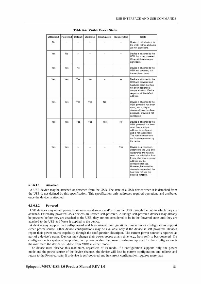
Spinpoint M9TU-USB 3.0 Product Manual REV 1.0 51
USB INTERFACE AND USB COMMANDS
Table 6-4: Visible Device States
6.3.6.1.1 Attached A USB device may be attached or detached from the USB. The state of a USB device when it is detached from
the USB is not defined by this specification. This specification only addresses required operations and attributes once the device is attached.
6.3.6.1.2 Powered USB devices may obtain power from an external source and/or from the USB through the hub to which they are
attached. Externally powered USB devices are termed self-powered. Although self-powered devices may already be powered before they are attached to the USB, they are not considered to be in the Powered state until they are attached to the USB and VBUS is applied to the device.
A device may support both self-powered and bus-powered configurations. Some device configurations support either power source. Other device configurations may be available only if the device is self powered. Devices report their power source capability through the configuration descriptor. The current power source is reported as part of a device’s status. Devices may change their power source at any time, e.g., from self- to bus-powered. If a configuration is capable of supporting both power modes, the power maximum reported for that configuration is the maximum the device will draw from VBUS in either mode.
The device must observe this maximum, regardless of its mode. If a configuration supports only one power mode and the power source of the device changes, the device will lose its current configuration and address and return to the Powered state. If a device is self-powered and its current configuration requires more than
Spinpoint M9TU-USB 3.0 Product Manual REV 1.0 52
USB INTERFACE AND USB COMMANDS
100 mA, then if the device switches to being bus-powered, it must return to the Address state. Self-powered hubs that use VBUS to power the Hub Controller are allowed to remain in the Configured state if local power is lost. A hub port must be powered in order to detect port status changes, including attach and detach. Bus powered
hubs do not provide any downstream power until they are configured, at which point they will provide power as allowed by their configuration and power source. A USB device must be able to be addressed within a specified time period from when power is initially applied. After an attachment to a port has been detected, the host may enable the port, which will also reset the device attached to the port.
6.3.6.1.3 Default After the device has been powered, it must not respond to any bus transactions until it has received a reset from
the bus. After receiving a reset, the device is then addressable at the default address. When the reset process is complete, the USB device is operating at the correct speed (i.e., low-/full-/highspeed). The speed selection for low- and full-speed is determined by the device termination resistors. A device that is
capable of high-speed operation determines whether it will operate at high-speed as a part of the reset process A device capable of high-speed operation must reset successfully at full-speed when in an electrical environment that is operating at full-speed. After the device is successfully reset, the device must also respond successfully to device and configuration descriptor requests and return appropriate information. The device may or may not be able to support its intended functionality when operating at full-speed.
6.3.6.1.4 Address All USB devices use the default address when initially powered or after the device has been reset. Each USB
device is assigned a unique address by the host after attachment or after reset. A USB device maintains its assigned address while suspended. A USB device responds to requests on its default pipe whether the device is currently assigned a unique address
or is using the default address. 6.3.6.1.5 Configured Before a USB device’s function may be used, the device must be configured. From the device’s perspective,
configuration involves correctly processing a SetConfiguration () request with a non-zero configuration value. Configuring a device or changing an alternate setting causes all of the status and configuration values associated with endpoints in the affected interfaces to be set to their default values. This includes setting the data toggle of any endpoint using data toggles to the value DATA0. 6.3.6.1.6 Suspended In order to conserve power, USB devices automatically enter the Suspended state when the device has observed no bus traffic for a specified period. When suspended, the USB device maintains any internal status, including its address and configuration. All devices must suspend if bus activity has not been observed for the length of time. Attached devices must be prepared to suspend at any time they are powered, whether they have been assigned a non-default address or are configured. Bus activity may cease due to the host entering a suspend mode of its own. In addition, a USB device shall also enter the Suspended state when the hub port it is attached to is disabled. This is referred to as selective suspend. A USB device exits suspend mode when there is bus activity. A USB device may also request the host to exit suspend mode or selective suspend by using electrical signaling to indicate remote wakeup. The ability of a device to signal remote wakeup is optional. If a USB device is capable of remote wakeup signaling, the device must support the ability of the host to enable and disable this capability. When the device is reset, remote wakeup signaling must be disabled. 6.3.6.1.7 Bus Enumeration Before an application can communicate with a device, the host needs to learn about what transfer types and endpoint the device support. The host also must assign an address to the device (Figure 6-29) When a USB device is attached to or removed from the USB, the host uses a process known as bus enumeration to identify and manage the device state changes necessary. When a USB device is attached to a powered port, the following actions are taken:
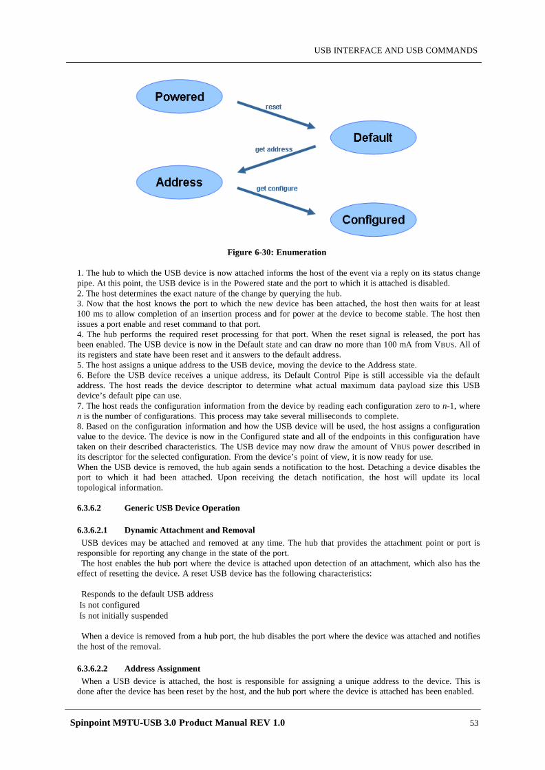
Spinpoint M9TU-USB 3.0 Product Manual REV 1.0 53
USB INTERFACE AND USB COMMANDS
Figure 6-30: Enumeration
1. The hub to which the USB device is now attached informs the host of the event via a reply on its status change pipe. At this point, the USB device is in the Powered state and the port to which it is attached is disabled. 2. The host determines the exact nature of the change by querying the hub. 3. Now that the host knows the port to which the new device has been attached, the host then waits for at least 100 ms to allow completion of an insertion process and for power at the device to become stable. The host then issues a port enable and reset command to that port. 4. The hub performs the required reset processing for that port. When the reset signal is released, the port has been enabled. The USB device is now in the Default state and can draw no more than 100 mA from VBUS. All of its registers and state have been reset and it answers to the default address. 5. The host assigns a unique address to the USB device, moving the device to the Address state. 6. Before the USB device receives a unique address, its Default Control Pipe is still accessible via the default address. The host reads the device descriptor to determine what actual maximum data payload size this USB device’s default pipe can use. 7. The host reads the configuration information from the device by reading each configuration zero to n-1, where n is the number of configurations. This process may take several milliseconds to complete. 8. Based on the configuration information and how the USB device will be used, the host assigns a configuration value to the device. The device is now in the Configured state and all of the endpoints in this configuration have taken on their described characteristics. The USB device may now draw the amount of VBUS power described in its descriptor for the selected configuration. From the device’s point of view, it is now ready for use. When the USB device is removed, the hub again sends a notification to the host. Detaching a device disables the port to which it had been attached. Upon receiving the detach notification, the host will update its local topological information. 6.3.6.2 Generic USB Device Operation 6.3.6.2.1 Dynamic Attachment and Removal USB devices may be attached and removed at any time. The hub that provides the attachment point or port is
responsible for reporting any change in the state of the port. The host enables the hub port where the device is attached upon detection of an attachment, which also has the
effect of resetting the device. A reset USB device has the following characteristics: Responds to the default USB address
Is not configured Is not initially suspended
When a device is removed from a hub port, the hub disables the port where the device was attached and notifies
the host of the removal.
6.3.6.2.2 Address Assignment When a USB device is attached, the host is responsible for assigning a unique address to the device. This is
done after the device has been reset by the host, and the hub port where the device is attached has been enabled.
Spinpoint M9TU-USB 3.0 Product Manual REV 1.0 54
USB INTERFACE AND USB COMMANDS
6.3.6.2.3 Configuration A USB device must be configured before its function(s) may be used. The host is responsible for configuring a
USB device. The host typically requests configuration information from the USB device to determine the device’s capabilities. As part of the configuration process, the host sets the device configuration and, where necessary, selects the
appropriate alternate settings for the interfaces. Within a single configuration, a device may support multiple interfaces. An interface is a related set of endpoints that present a single feature or function of the device to the host. The protocol used to communicate with this related set of endpoints and the purpose of each endpoint within the interface may be specified as part of a device class or vendor-specific definition. In addition, an interface within a configuration may have alternate settings that redefine the number or characteristics of the associated endpoints. If this is the case, the device must support the GetInterface() request to report the current alternate setting for the specified interface and SetInterface() request to select the alternate setting for the specified interface. Within each configuration, each interface descriptor contains fields that identify the interface number and the
alternate setting. Interfaces are numbered from zero to one less than the number of concurrent interfaces supported by the configuration. Alternate settings range from zero to one less than the number of alternate settings for a specific interface. The default setting when a device is initially configured is alternate setting zero.
In support of adaptive device drivers that are capable of managing a related group of USB devices, the device and interface descriptors contain Class, SubClass, and Protocol fields. These fields are used to identify the function(s) provided by a USB device and the protocols used to communicate with the function(s) on the device. A class code is assigned to a group of related devices that has been characterized as a part of a USB Class Specification. A class of devices may be further subdivided into subclasses, and, within a class or subclass, a protocol code may define how the Host Software communicates with the device. Note: The assignment of class, subclass, and protocol codes must be coordinated but is beyond the scope of this
specification.
6.3.6.2.4 Data Transfer Data may be transferred between a USB device endpoint and the host in one of four ways. An endpoint number may be used for different types of data transfers in different alternate settings. However, once an alternate setting is selected (including the default setting of an interface), a USB device endpoint uses only one data transfer method until a different alternate setting is selected.
6.3.6.2.5 Power Management Power Budgeting USB bus power is a limited resource. During device enumeration, a host evaluates a device’s power
requirements. If the power requirements of a particular configuration exceed the power available to the device, Host Software shall not select that configuration. USB devices shall limit the power they consume from VBUS to one unit load or less until configured. Suspended devices, whether configured or not, shall limit their bus power consumption. Depending on the power capabilities of the port to which the device is attached, a USB device may be able to draw up to five unit loads from VBUS after configuration.
Remote WakeUp Remote wakeup allows a suspended USB device to signal a host that may also be suspended. This notifies the
host that it should resume from its suspended mode, if necessary, and service the external event that triggered the suspended USB device to signal the host. A USB device reports its ability to support remote wakeup in a configuration descriptor. If a device supports remote wakeup, it must also allow the capability to be enabled and disabled using the standard USB requests.
6.3.6.2.6 Request Processing With the exception of SetAddress() requests, a device may begin processing of a request as soon as the device
returns the ACK following the Setup. The device is expected to “complete” processing of the request before it allows the Status stage to complete successfully. Some requests initiate operations that take many milliseconds to complete. For requests such as this, the device class is required to define a method other than Status stage completion to indicate that the operation has completed. For example, a reset on a hub port takes at least 10 ms to complete. The SetPortFeature(PORT_RESET) request “completes” when the reset on the port is initiated. Completion of the reset operation is signaled when the port’s status change is set to indicate that the port is now enabled
6.3.6.3 Standard USB Device Requests All USB devices respond to requests from the host on the device’s Default Control Pipe. These requests are
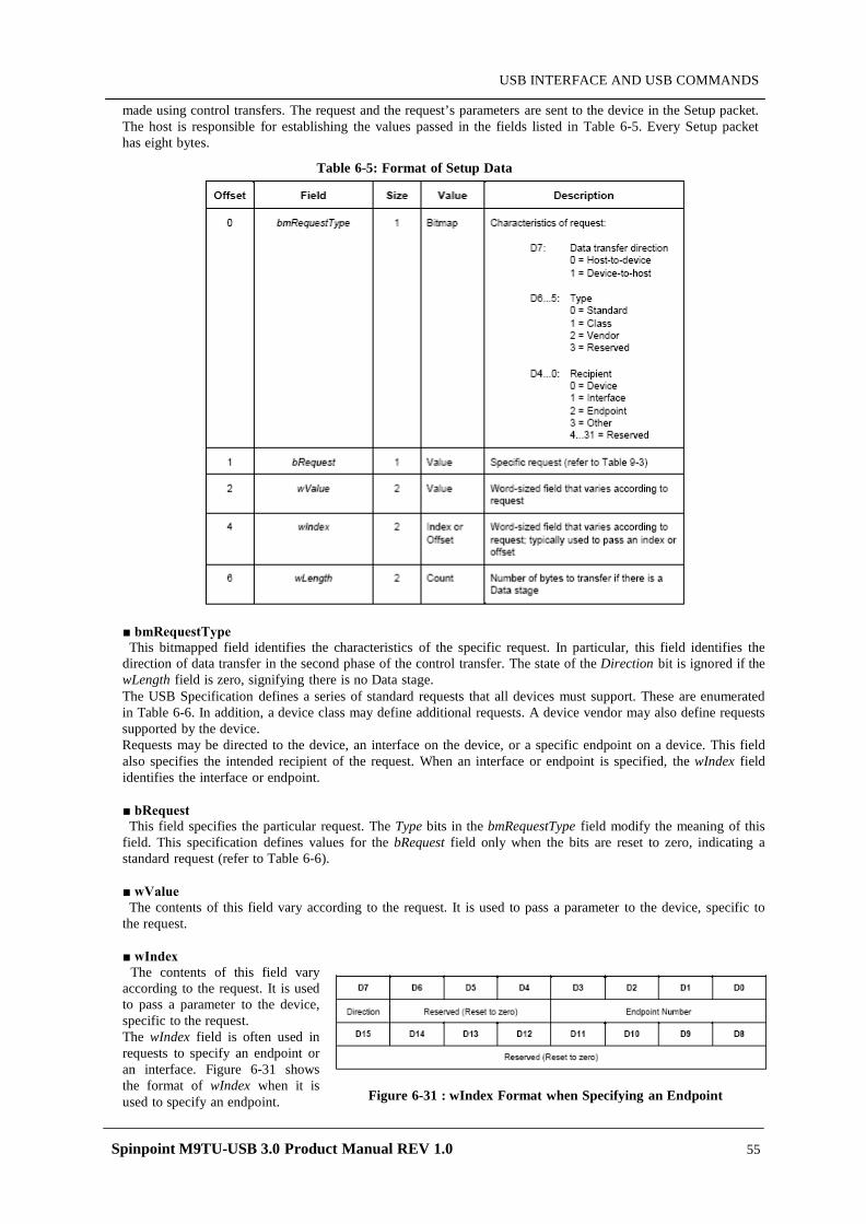
Spinpoint M9TU-USB 3.0 Product Manual REV 1.0 55
USB INTERFACE AND USB COMMANDS
made using control transfers. The request and the request’s parameters are sent to the device in the Setup packet. The host is responsible for establishing the values passed in the fields listed in Table 6-5. Every Setup packet has eight bytes.
Table 6-5: Format of Setup Data
bmRequestType This bitmapped field identifies the characteristics of the specific request. In particular, this field identifies the
direction of data transfer in the second phase of the control transfer. The state of the Direction bit is ignored if the wLength field is zero, signifying there is no Data stage. The USB Specification defines a series of standard requests that all devices must support. These are enumerated in Table 6-6. In addition, a device class may define additional requests. A device vendor may also define requests supported by the device. Requests may be directed to the device, an interface on the device, or a specific endpoint on a device. This field also specifies the intended recipient of the request. When an interface or endpoint is specified, the wIndex field identifies the interface or endpoint.
bRequest This field specifies the particular request. The Type bits in the bmRequestType field modify the meaning of this
field. This specification defines values for the bRequest field only when the bits are reset to zero, indicating a standard request (refer to Table 6-6).
wValue The contents of this field vary according to the request. It is used to pass a parameter to the device, specific to
the request.
wIndex The contents of this field vary
according to the request. It is used to pass a parameter to the device, specific to the request. The wIndex field is often used in requests to specify an endpoint or an interface. Figure 6-31 shows the format of wIndex when it is used to specify an endpoint. Figure 6-31 : wIndex Format when Specifying an Endpoint
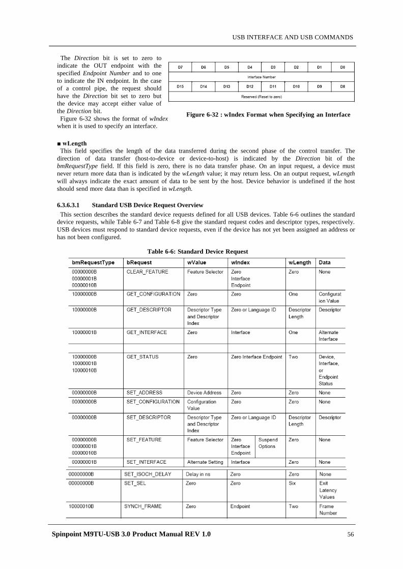
Spinpoint M9TU-USB 3.0 Product Manual REV 1.0 56
USB INTERFACE AND USB COMMANDS
The Direction bit is set to zero to
indicate the OUT endpoint with the specified Endpoint Number and to one to indicate the IN endpoint. In the case of a control pipe, the request should have the Direction bit set to zero but the device may accept either value of the Direction bit. Figure 6-32 shows the format of wIndex
when it is used to specify an interface.
wLength This field specifies the length of the data transferred during the second phase of the control transfer. The
direction of data transfer (host-to-device or device-to-host) is indicated by the Direction bit of the bmRequestType field. If this field is zero, there is no data transfer phase. On an input request, a device must never return more data than is indicated by the wLength value; it may return less. On an output request, wLength will always indicate the exact amount of data to be sent by the host. Device behavior is undefined if the host should send more data than is specified in wLength.
6.3.6.3.1 Standard USB Device Request Overview This section describes the standard device requests defined for all USB devices. Table 6-6 outlines the standard
device requests, while Table 6-7 and Table 6-8 give the standard request codes and descriptor types, respectively. USB devices must respond to standard device requests, even if the device has not yet been assigned an address or has not been configured.
Table 6-6: Standard Device Request
Figure 6-32 : wIndex Format when Specifying an Interface
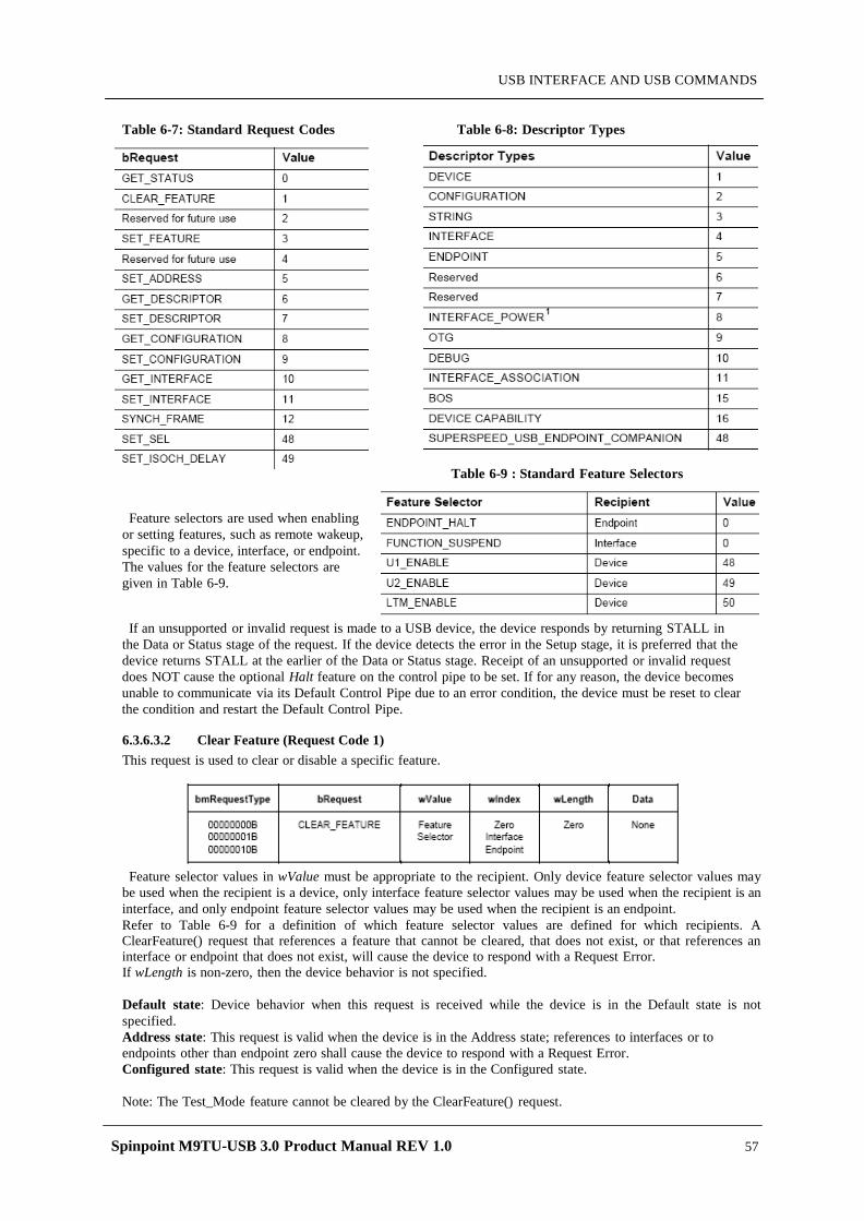
Spinpoint M9TU-USB 3.0 Product Manual REV 1.0 57
USB INTERFACE AND USB COMMANDS
Table 6-7: Standard Request Codes Table 6-8: Descriptor Types
Feature selectors are used when enabling or setting features, such as remote wakeup, specific to a device, interface, or endpoint. The values for the feature selectors are given in Table 6-9.
If an unsupported or invalid request is made to a USB device, the device responds by returning STALL in the Data or Status stage of the request. If the device detects the error in the Setup stage, it is preferred that the device returns STALL at the earlier of the Data or Status stage. Receipt of an unsupported or invalid request does NOT cause the optional Halt feature on the control pipe to be set. If for any reason, the device becomes unable to communicate via its Default Control Pipe due to an error condition, the device must be reset to clear the condition and restart the Default Control Pipe.
6.3.6.3.2 Clear Feature (Request Code 1) This request is used to clear or disable a specific feature.
Feature selector values in wValue must be appropriate to the recipient. Only device feature selector values may
be used when the recipient is a device, only interface feature selector values may be used when the recipient is an interface, and only endpoint feature selector values may be used when the recipient is an endpoint. Refer to Table 6-9 for a definition of which feature selector values are defined for which recipients. A ClearFeature() request that references a feature that cannot be cleared, that does not exist, or that references an interface or endpoint that does not exist, will cause the device to respond with a Request Error. If wLength is non-zero, then the device behavior is not specified.
Default state: Device behavior when this request is received while the device is in the Default state is not specified. Address state: This request is valid when the device is in the Address state; references to interfaces or to endpoints other than endpoint zero shall cause the device to respond with a Request Error. Configured state: This request is valid when the device is in the Configured state.
Note: The Test_Mode feature cannot be cleared by the ClearFeature() request.
Table 6-9 : Standard Feature Selectors
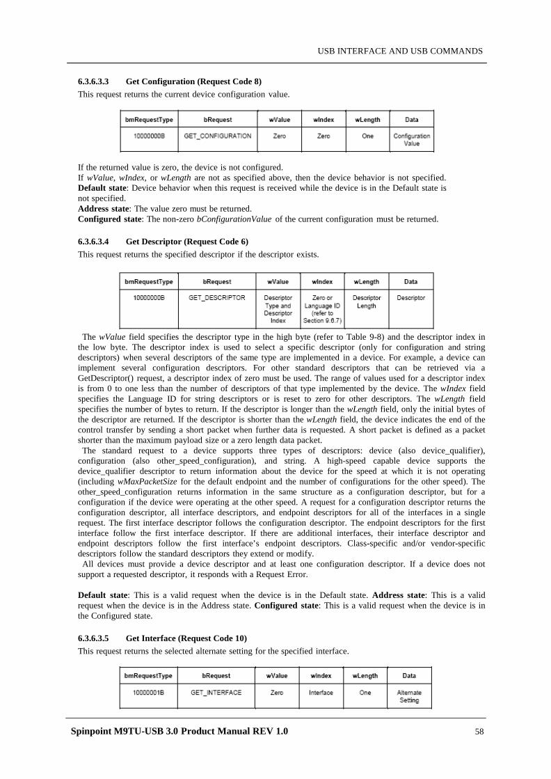
Spinpoint M9TU-USB 3.0 Product Manual REV 1.0 58
USB INTERFACE AND USB COMMANDS
6.3.6.3.3 Get Configuration (Request Code 8) This request returns the current device configuration value.
If the returned value is zero, the device is not configured. If wValue, wIndex, or wLength are not as specified above, then the device behavior is not specified. Default state: Device behavior when this request is received while the device is in the Default state is not specified. Address state: The value zero must be returned. Configured state: The non-zero bConfigurationValue of the current configuration must be returned.
6.3.6.3.4 Get Descriptor (Request Code 6) This request returns the specified descriptor if the descriptor exists.
The wValue field specifies the descriptor type in the high byte (refer to Table 9-8) and the descriptor index in
the low byte. The descriptor index is used to select a specific descriptor (only for configuration and string descriptors) when several descriptors of the same type are implemented in a device. For example, a device can implement several configuration descriptors. For other standard descriptors that can be retrieved via a GetDescriptor() request, a descriptor index of zero must be used. The range of values used for a descriptor index is from 0 to one less than the number of descriptors of that type implemented by the device. The wIndex field specifies the Language ID for string descriptors or is reset to zero for other descriptors. The wLength field specifies the number of bytes to return. If the descriptor is longer than the wLength field, only the initial bytes of the descriptor are returned. If the descriptor is shorter than the wLength field, the device indicates the end of the control transfer by sending a short packet when further data is requested. A short packet is defined as a packet shorter than the maximum payload size or a zero length data packet.
The standard request to a device supports three types of descriptors: device (also device_qualifier), configuration (also other_speed_configuration), and string. A high-speed capable device supports the device_qualifier descriptor to return information about the device for the speed at which it is not operating (including wMaxPacketSize for the default endpoint and the number of configurations for the other speed). The other_speed_configuration returns information in the same structure as a configuration descriptor, but for a configuration if the device were operating at the other speed. A request for a configuration descriptor returns the configuration descriptor, all interface descriptors, and endpoint descriptors for all of the interfaces in a single request. The first interface descriptor follows the configuration descriptor. The endpoint descriptors for the first interface follow the first interface descriptor. If there are additional interfaces, their interface descriptor and endpoint descriptors follow the first interface’s endpoint descriptors. Class-specific and/or vendor-specific descriptors follow the standard descriptors they extend or modify.
All devices must provide a device descriptor and at least one configuration descriptor. If a device does not support a requested descriptor, it responds with a Request Error.
Default state: This is a valid request when the device is in the Default state. Address state: This is a valid request when the device is in the Address state. Configured state: This is a valid request when the device is in the Configured state.
6.3.6.3.5 Get Interface (Request Code 10) This request returns the selected alternate setting for the specified interface.
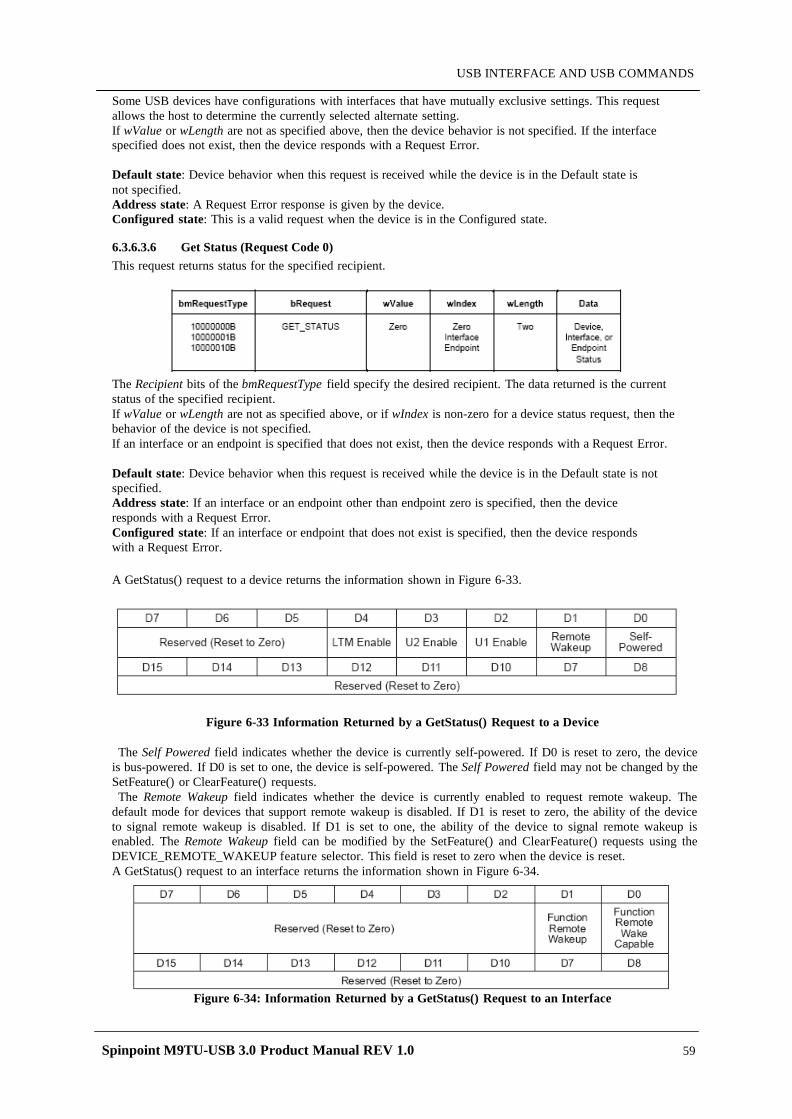
Spinpoint M9TU-USB 3.0 Product Manual REV 1.0 59
USB INTERFACE AND USB COMMANDS
Some USB devices have configurations with interfaces that have mutually exclusive settings. This request allows the host to determine the currently selected alternate setting. If wValue or wLength are not as specified above, then the device behavior is not specified. If the interface specified does not exist, then the device responds with a Request Error.
Default state: Device behavior when this request is received while the device is in the Default state is not specified. Address state: A Request Error response is given by the device. Configured state: This is a valid request when the device is in the Configured state.
6.3.6.3.6 Get Status (Request Code 0) This request returns status for the specified recipient.
The Recipient bits of the bmRequestType field specify the desired recipient. The data returned is the current status of the specified recipient. If wValue or wLength are not as specified above, or if wIndex is non-zero for a device status request, then the behavior of the device is not specified. If an interface or an endpoint is specified that does not exist, then the device responds with a Request Error.
Default state: Device behavior when this request is received while the device is in the Default state is not specified. Address state: If an interface or an endpoint other than endpoint zero is specified, then the device responds with a Request Error. Configured state: If an interface or endpoint that does not exist is specified, then the device responds with a Request Error.
A GetStatus() request to a device returns the information shown in Figure 6-33.
Figure 6-33 Information Returned by a GetStatus() Request to a Device
The Self Powered field indicates whether the device is currently self-powered. If D0 is reset to zero, the device is bus-powered. If D0 is set to one, the device is self-powered. The Self Powered field may not be changed by the SetFeature() or ClearFeature() requests. The Remote Wakeup field indicates whether the device is currently enabled to request remote wakeup. The
default mode for devices that support remote wakeup is disabled. If D1 is reset to zero, the ability of the device to signal remote wakeup is disabled. If D1 is set to one, the ability of the device to signal remote wakeup is enabled. The Remote Wakeup field can be modified by the SetFeature() and ClearFeature() requests using the DEVICE_REMOTE_WAKEUP feature selector. This field is reset to zero when the device is reset. A GetStatus() request to an interface returns the information shown in Figure 6-34.
Figure 6-34: Information Returned by a GetStatus() Request to an Interface
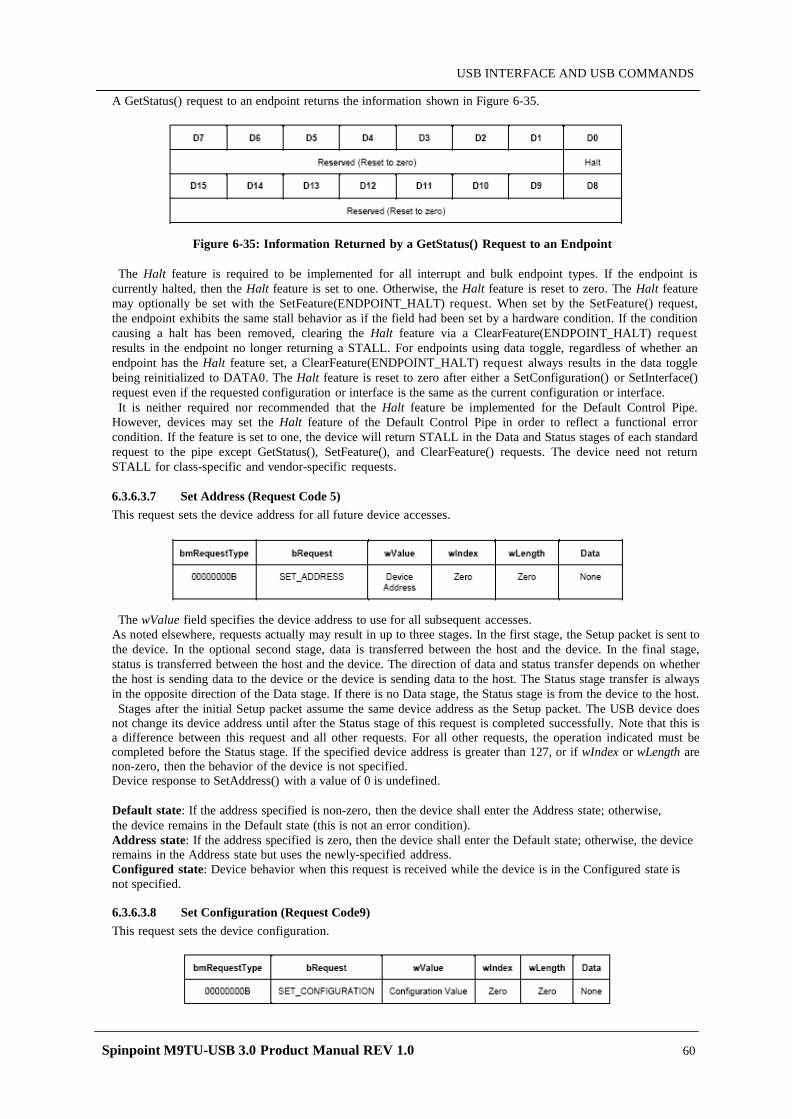
Spinpoint M9TU-USB 3.0 Product Manual REV 1.0 60
USB INTERFACE AND USB COMMANDS
A GetStatus() request to an endpoint returns the information shown in Figure 6-35.
Figure 6-35: Information Returned by a GetStatus() Request to an Endpoint
The Halt feature is required to be implemented for all interrupt and bulk endpoint types. If the endpoint is currently halted, then the Halt feature is set to one. Otherwise, the Halt feature is reset to zero. The Halt feature may optionally be set with the SetFeature(ENDPOINT_HALT) request. When set by the SetFeature() request, the endpoint exhibits the same stall behavior as if the field had been set by a hardware condition. If the condition causing a halt has been removed, clearing the Halt feature via a ClearFeature(ENDPOINT_HALT) request results in the endpoint no longer returning a STALL. For endpoints using data toggle, regardless of whether an endpoint has the Halt feature set, a ClearFeature(ENDPOINT_HALT) request always results in the data toggle being reinitialized to DATA0. The Halt feature is reset to zero after either a SetConfiguration() or SetInterface() request even if the requested configuration or interface is the same as the current configuration or interface. It is neither required nor recommended that the Halt feature be implemented for the Default Control Pipe.
However, devices may set the Halt feature of the Default Control Pipe in order to reflect a functional error condition. If the feature is set to one, the device will return STALL in the Data and Status stages of each standard request to the pipe except GetStatus(), SetFeature(), and ClearFeature() requests. The device need not return STALL for class-specific and vendor-specific requests. 6.3.6.3.7 Set Address (Request Code 5) This request sets the device address for all future device accesses.
The wValue field specifies the device address to use for all subsequent accesses. As noted elsewhere, requests actually may result in up to three stages. In the first stage, the Setup packet is sent to the device. In the optional second stage, data is transferred between the host and the device. In the final stage, status is transferred between the host and the device. The direction of data and status transfer depends on whether the host is sending data to the device or the device is sending data to the host. The Status stage transfer is always in the opposite direction of the Data stage. If there is no Data stage, the Status stage is from the device to the host. Stages after the initial Setup packet assume the same device address as the Setup packet. The USB device does
not change its device address until after the Status stage of this request is completed successfully. Note that this is a difference between this request and all other requests. For all other requests, the operation indicated must be completed before the Status stage. If the specified device address is greater than 127, or if wIndex or wLength are non-zero, then the behavior of the device is not specified. Device response to SetAddress() with a value of 0 is undefined.
Default state: If the address specified is non-zero, then the device shall enter the Address state; otherwise, the device remains in the Default state (this is not an error condition). Address state: If the address specified is zero, then the device shall enter the Default state; otherwise, the device remains in the Address state but uses the newly-specified address. Configured state: Device behavior when this request is received while the device is in the Configured state is not specified.
6.3.6.3.8 Set Configuration (Request Code9) This request sets the device configuration.

Spinpoint M9TU-USB 3.0 Product Manual REV 1.0 61
USB INTERFACE AND USB COMMANDS
The lower byte of the wValue field specifies the desired configuration. This configuration value must be zero or match a configuration value from a configuration descriptor. If the configuration value is zero, the device is placed in its Address state. The upper byte of the wValue field is reserved. If wIndex, wLength, or the upper byte of wValue is non-zero, then the behavior of this request is not specified.
Default state: Device behavior when this request is received while the device is in the Default state is not specified. Address state: If the specified configuration value is zero, then the device remains in the Address state. If the specified configuration value matches the configuration value from a configuration descriptor, then that configuration is selected and the device enters the Configured state. Otherwise, the device responds with a Request Error. Configured state: If the specified configuration value is zero, then the device enters the Address state. If the specified configuration value matches the configuration value from a configuration descriptor, then that configuration is selected and the device remains in the Configured state. Otherwise, the device responds with a Request Error.
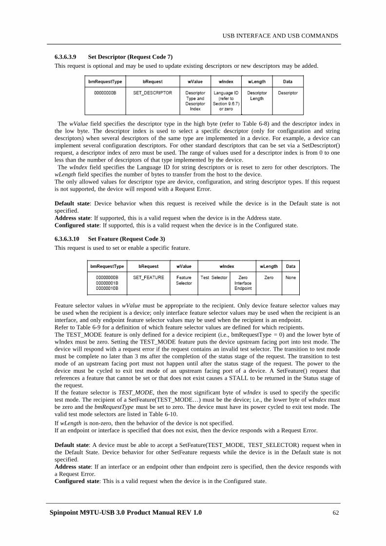
Spinpoint M9TU-USB 3.0 Product Manual REV 1.0 62
USB INTERFACE AND USB COMMANDS
6.3.6.3.9 Set Descriptor (Request Code 7) This request is optional and may be used to update existing descriptors or new descriptors may be added.
The wValue field specifies the descriptor type in the high byte (refer to Table 6-8) and the descriptor index in the low byte. The descriptor index is used to select a specific descriptor (only for configuration and string descriptors) when several descriptors of the same type are implemented in a device. For example, a device can implement several configuration descriptors. For other standard descriptors that can be set via a SetDescriptor() request, a descriptor index of zero must be used. The range of values used for a descriptor index is from 0 to one less than the number of descriptors of that type implemented by the device.
The wIndex field specifies the Language ID for string descriptors or is reset to zero for other descriptors. The wLength field specifies the number of bytes to transfer from the host to the device. The only allowed values for descriptor type are device, configuration, and string descriptor types. If this request is not supported, the device will respond with a Request Error.
Default state: Device behavior when this request is received while the device is in the Default state is not specified. Address state: If supported, this is a valid request when the device is in the Address state. Configured state: If supported, this is a valid request when the device is in the Configured state.
6.3.6.3.10 Set Feature (Request Code 3) This request is used to set or enable a specific feature.
Feature selector values in wValue must be appropriate to the recipient. Only device feature selector values may be used when the recipient is a device; only interface feature selector values may be used when the recipient is an interface, and only endpoint feature selector values may be used when the recipient is an endpoint. Refer to Table 6-9 for a definition of which feature selector values are defined for which recipients. The TEST_MODE feature is only defined for a device recipient (i.e., bmRequestType = 0) and the lower byte of wIndex must be zero. Setting the TEST_MODE feature puts the device upstream facing port into test mode. The device will respond with a request error if the request contains an invalid test selector. The transition to test mode must be complete no later than 3 ms after the completion of the status stage of the request. The transition to test mode of an upstream facing port must not happen until after the status stage of the request. The power to the device must be cycled to exit test mode of an upstream facing port of a device. A SetFeature() request that references a feature that cannot be set or that does not exist causes a STALL to be returned in the Status stage of the request. If the feature selector is TEST_MODE, then the most significant byte of wIndex is used to specify the specific test mode. The recipient of a SetFeature(TEST_MODE…) must be the device; i.e., the lower byte of wIndex must be zero and the bmRequestType must be set to zero. The device must have its power cycled to exit test mode. The valid test mode selectors are listed in Table 6-10. If wLength is non-zero, then the behavior of the device is not specified. If an endpoint or interface is specified that does not exist, then the device responds with a Request Error.
Default state: A device must be able to accept a SetFeature(TEST_MODE, TEST_SELECTOR) request when in the Default State. Device behavior for other SetFeature requests while the device is in the Default state is not specified. Address state: If an interface or an endpoint other than endpoint zero is specified, then the device responds with a Request Error. Configured state: This is a valid request when the device is in the Configured state.
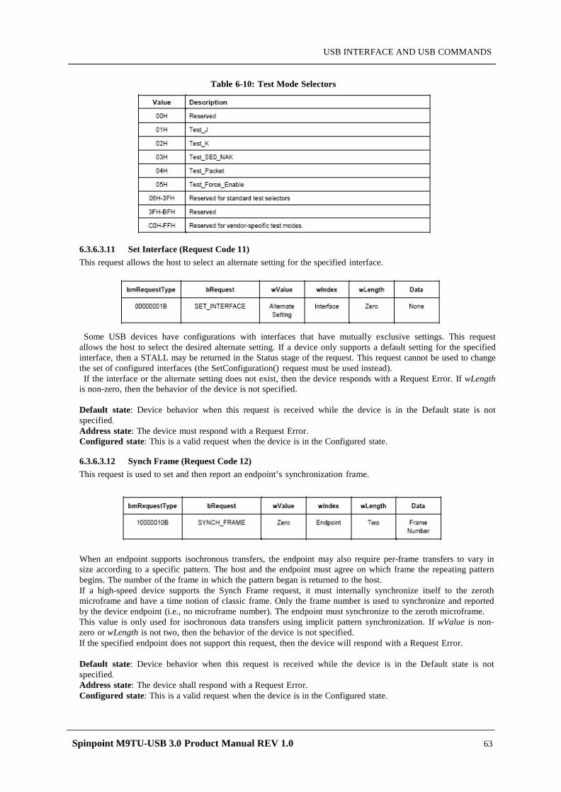
Spinpoint M9TU-USB 3.0 Product Manual REV 1.0 63
USB INTERFACE AND USB COMMANDS
Table 6-10: Test Mode Selectors
6.3.6.3.11 Set Interface (Request Code 11) This request allows the host to select an alternate setting for the specified interface.
Some USB devices have configurations with interfaces that have mutually exclusive settings. This request allows the host to select the desired alternate setting. If a device only supports a default setting for the specified interface, then a STALL may be returned in the Status stage of the request. This request cannot be used to change the set of configured interfaces (the SetConfiguration() request must be used instead). If the interface or the alternate setting does not exist, then the device responds with a Request Error. If wLength
is non-zero, then the behavior of the device is not specified.
Default state: Device behavior when this request is received while the device is in the Default state is not specified. Address state: The device must respond with a Request Error. Configured state: This is a valid request when the device is in the Configured state.
6.3.6.3.12 Synch Frame (Request Code 12) This request is used to set and then report an endpoint’s synchronization frame.
When an endpoint supports isochronous transfers, the endpoint may also require per-frame transfers to vary in size according to a specific pattern. The host and the endpoint must agree on which frame the repeating pattern begins. The number of the frame in which the pattern began is returned to the host. If a high-speed device supports the Synch Frame request, it must internally synchronize itself to the zeroth microframe and have a time notion of classic frame. Only the frame number is used to synchronize and reported by the device endpoint (i.e., no microframe number). The endpoint must synchronize to the zeroth microframe. This value is only used for isochronous data transfers using implicit pattern synchronization. If wValue is non-zero or wLength is not two, then the behavior of the device is not specified. If the specified endpoint does not support this request, then the device will respond with a Request Error.
Default state: Device behavior when this request is received while the device is in the Default state is not specified. Address state: The device shall respond with a Request Error. Configured state: This is a valid request when the device is in the Configured state.
Spinpoint M9TU-USB 3.0 Product Manual REV 1.0 64
USB INTERFACE AND USB COMMANDS
6.3.6.4 Standard USB Descriptor The standard descriptors defined in this specification may only be modified or extended by revision of the
Universal Serial Bus Specification. Note: An extension to the USB 1.0 standard endpoint descriptor has been published in Device Class Specification for Audio Devices Revision 1.0. This is the only extension defined outside USB Specification that is allowed. Future revisions of the USB Specification that extend the standard endpoint descriptor will do so as to not conflict with the extension defined in the Audio Device Class Specification Revision 1.0.
6.3.6.4.1 Standard USB Descriptor Overview USB devices report their attributes using descriptors. A descriptor is a data structure with a defined format. Each
descriptor begins with a byte-wide field that contains the total number of bytes in the descriptor followed by a byte-wide field that identifies the descriptor type. Using descriptors allows concise storage of the attributes of individual configurations because each
configuration may reuse descriptors or portions of descriptors from other configurations that have the same characteristics. In this manner, the descriptors resemble individual data records in a relational database. Where appropriate, descriptors contain references to string descriptors that provide displayable information describing a descriptor in human-readable form. The inclusion of string descriptors is optional. However, the reference fields within descriptors are mandatory. If a device does not support string descriptors, string reference fields must be reset to zero to indicate no string descriptor is available. If a descriptor returns with a value in its length field that is less than defined by this specification, the descriptor
is invalid and should be rejected by the host. If the descriptor returns with a value in its length field that is greater than defined by this specification, the extra bytes are ignored by the host, but the next descriptor is located using the length returned rather than the length expected.
A device may return class- or vendor-specific descriptors in two ways:
1. If the class or vendor specific descriptors use the same format as standard descriptors (e.g., start with a length byte and followed by a type byte), they must be returned interleaved with standard descriptors in the configuration information returned by a GetDescriptor(Configuration) request. In this case, the class or vendor-specific descriptors must follow a related standard descriptor they modify or extend. 2. If the class or vendor specific descriptors are independent of configuration information or use a nonstandard format, a GetDescriptor() request specifying the class or vendor specific descriptor type and index may be used to retrieve the descriptor from the device. A class or vendor specification will define the appropriate way to retrieve these descriptors. 6.3.6.4.2 Device Descriptor A device descriptor describes general information about a USB device. It includes information that applies
globally to the device and all of the device’s configurations. A USB device has only one device descriptor. A high-speed capable device that has different device information for full-speed and high-speed must also have a device_qualifier descriptor.
The DEVICE descriptor of a high-speed capable device has a version number of 2.0 (0200H). If the device is full-speed only or low-speed only, this version number indicates that it will respond correctly to a request for the device_qualifier descriptor (i.e., it will respond with a request error). The bcdUSB field contains a BCD version number. The value of the bcdUSB field is 0xJJMN for version JJ.M.N (JJ – major version number, M – minor version number, N – sub-minor version number), e.g., version 2.1.3 is represented with value 0x0213 and version 2.0 is represented with a value of 0x0200. The bNumConfigurations field indicates the number of configurations at the current operating speed. Configurations for the other operating speed are not included in the count. If there are specific configurations of the device for specific speeds, the bNumConfigurations field only reflects the number of configurations for a single speed, not the total number of configurations for both speeds. If the device is operating at high-speed, the bMaxPacketSize0 field must be 64 indicating a 64 byte maximum packet. High-speed operation does not allow other maximum packet sizes for the control endpoint (endpoint 0). All USB devices have a Default Control Pipe. The maximum packet size of a device’s Default Control Pipe is described in the device descriptor. Endpoints specific to a configuration and its interface(s) are described in the configuration descriptor. A configuration and its interface(s) do not include an endpoint descriptor for the Default Control Pipe. Other than the maximum packet size, the characteristics of the Default Control Pipe are defined by this specification and are the same for all USB devices. The bNumConfigurations field identifies the number of configurations the device supports. Table 6-11 shows the standard device descriptor.
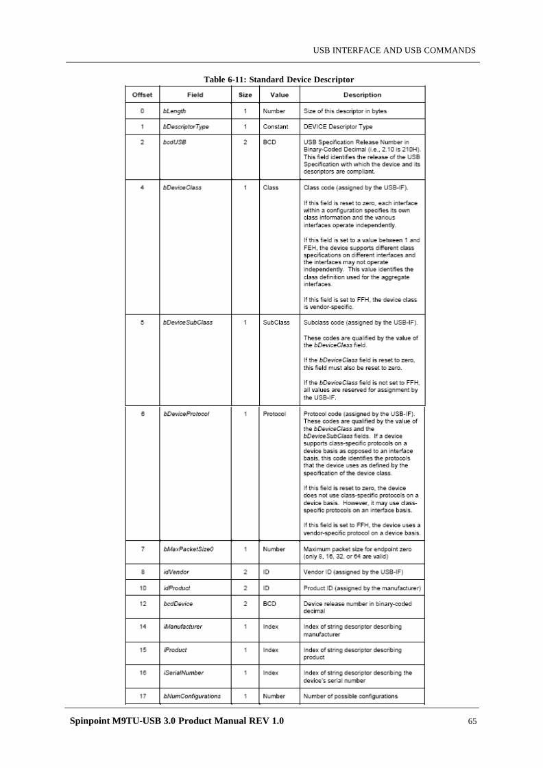
Spinpoint M9TU-USB 3.0 Product Manual REV 1.0 65
USB INTERFACE AND USB COMMANDS
Table 6-11: Standard Device Descriptor
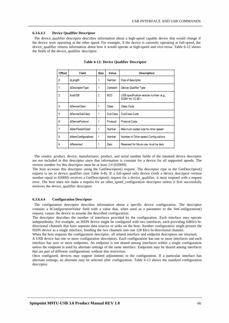
Spinpoint M9TU-USB 3.0 Product Manual REV 1.0 66
USB INTERFACE AND USB COMMANDS
6.3.6.4.3 Device Qualifier Descriptor The device_qualifier descriptor describes information about a high-speed capable device that would change if
the device were operating at the other speed. For example, if the device is currently operating at full-speed, the device_qualifier returns information about how it would operate at high-speed and vice-versa. Table 6-12 shows the fields of the device_qualifier descriptor.
Table 6-12: Device Qualifier Descriptor
The vendor, product, device, manufacturer, product, and serial number fields of the standard device descriptor are not included in this descriptor since that information is constant for a device for all supported speeds. The version number for this descriptor must be at least 2.0 (0200H). The host accesses this descriptor using the GetDescriptor() request. The descriptor type in the GetDescriptor() request is set to device_qualifier (see Table 6-8). If a full-speed only device (with a device descriptor version number equal to 0200H) receives a GetDescriptor() request for a device_qualifier, it must respond with a request error. The host must not make a request for an other_speed_configuration descriptor unless it first successfully retrieves the device_qualifier descriptor.
6.3.6.4.4 Configuration Descriptor The configuration descriptor describes information about a specific device configuration. The descriptor
contains a bConfigurationValue field with a value that, when used as a parameter to the SetConfiguration() request, causes the device to assume the described configuration. The descriptor describes the number of interfaces provided by the configuration. Each interface may operate independently. For example, an ISDN device might be configured with two interfaces, each providing 64Kb/s bi-directional channels that have separate data sources or sinks on the host. Another configuration might present the ISDN device as a single interface, bonding the two channels into one 128 Kb/s bi-directional channel. When the host requests the configuration descriptor, all related interface and endpoint descriptors are returned. A USB device has one or more configuration descriptors. Each configuration has one or more interfaces and each interface has zero or more endpoints. An endpoint is not shared among interfaces within a single configuration unless the endpoint is used by alternate settings of the same interface. Endpoints may be shared among interfaces that are part of different configurations without this restriction. Once configured, devices may support limited adjustments to the configuration. If a particular interface has alternate settings, an alternate may be selected after configuration. Table 6-13 shows the standard configuration descriptor.
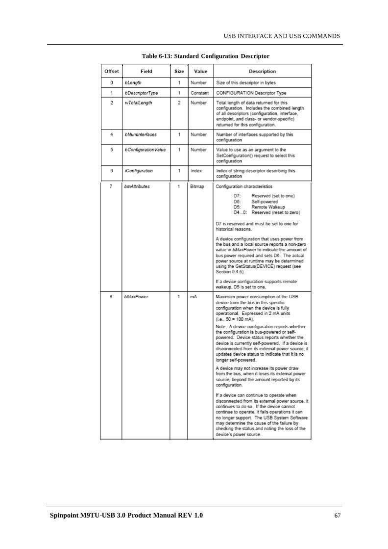
Spinpoint M9TU-USB 3.0 Product Manual REV 1.0 67
USB INTERFACE AND USB COMMANDS
Table 6-13: Standard Configuration Descriptor
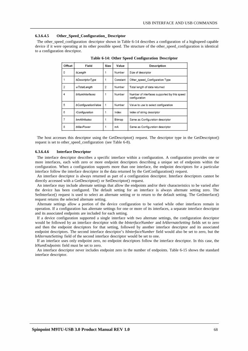
Spinpoint M9TU-USB 3.0 Product Manual REV 1.0 68
USB INTERFACE AND USB COMMANDS
6.3.6.4.5 Other_Speed_Configuration_ Descriptor The other_speed_configuration descriptor shown in Table 6-14 describes a configuration of a highspeed capable
device if it were operating at its other possible speed. The structure of the other_speed_configuration is identical to a configuration descriptor.
Table 6-14: Other Speed Configuration Descriptor
The host accesses this descriptor using the GetDescriptor() request. The descriptor type in the GetDescriptor() request is set to other_speed_configuration (see Table 6-8).
6.3.6.4.6 Interface Descriptor The interface descriptor describes a specific interface within a configuration. A configuration provides one or
more interfaces, each with zero or more endpoint descriptors describing a unique set of endpoints within the configuration. When a configuration supports more than one interface, the endpoint descriptors for a particular interface follow the interface descriptor in the data returned by the GetConfiguration() request.
An interface descriptor is always returned as part of a configuration descriptor. Interface descriptors cannot be directly accessed with a GetDescriptor() or SetDescriptor() request. An interface may include alternate settings that allow the endpoints and/or their characteristics to be varied after
the device has been configured. The default setting for an interface is always alternate setting zero. The SetInterface() request is used to select an alternate setting or to return to the default setting. The GetInterface() request returns the selected alternate setting. Alternate settings allow a portion of the device configuration to be varied while other interfaces remain in
operation. If a configuration has alternate settings for one or more of its interfaces, a separate interface descriptor and its associated endpoints are included for each setting.
If a device configuration supported a single interface with two alternate settings, the configuration descriptor would be followed by an interface descriptor with the bInterfaceNumber and bAlternateSetting fields set to zero and then the endpoint descriptors for that setting, followed by another interface descriptor and its associated endpoint descriptors. The second interface descriptor’s bInterfaceNumber field would also be set to zero, but the bAlternateSetting field of the second interface descriptor would be set to one. If an interface uses only endpoint zero, no endpoint descriptors follow the interface descriptor. In this case, the
bNumEndpoints field must be set to zero. An interface descriptor never includes endpoint zero in the number of endpoints. Table 6-15 shows the standard
interface descriptor.
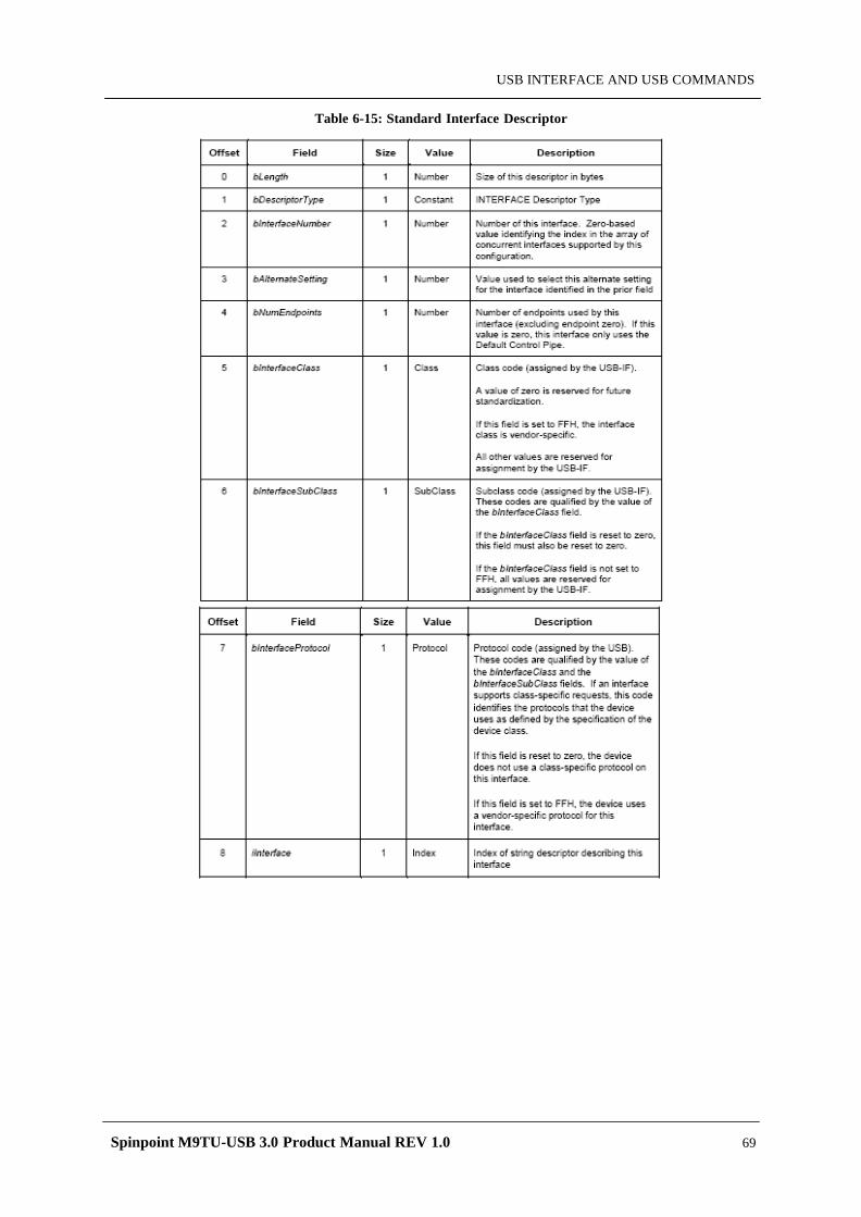
Spinpoint M9TU-USB 3.0 Product Manual REV 1.0 69
USB INTERFACE AND USB COMMANDS
Table 6-15: Standard Interface Descriptor
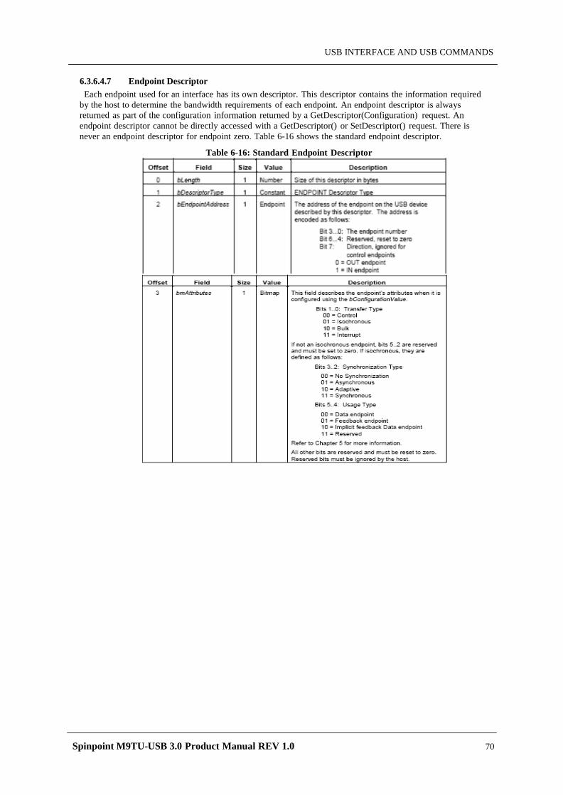
Spinpoint M9TU-USB 3.0 Product Manual REV 1.0 70
USB INTERFACE AND USB COMMANDS
6.3.6.4.7 Endpoint Descriptor Each endpoint used for an interface has its own descriptor. This descriptor contains the information required
by the host to determine the bandwidth requirements of each endpoint. An endpoint descriptor is always returned as part of the configuration information returned by a GetDescriptor(Configuration) request. An endpoint descriptor cannot be directly accessed with a GetDescriptor() or SetDescriptor() request. There is never an endpoint descriptor for endpoint zero. Table 6-16 shows the standard endpoint descriptor.
Table 6-16: Standard Endpoint Descriptor
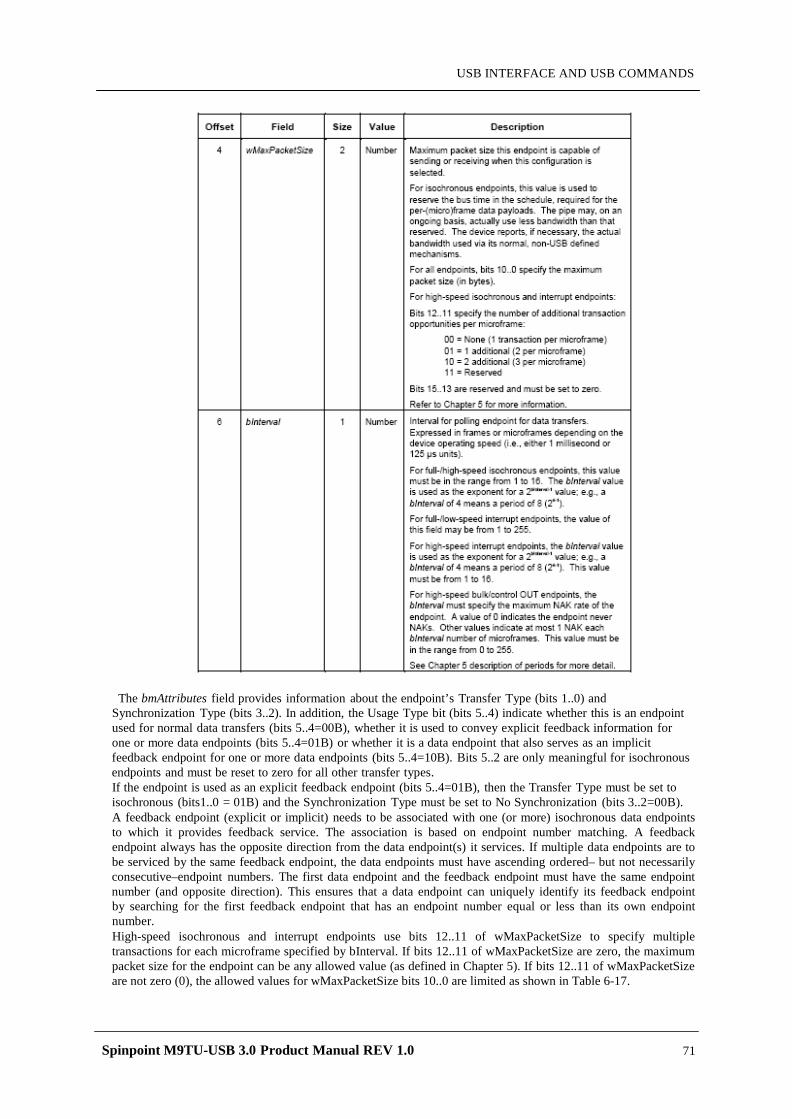
Spinpoint M9TU-USB 3.0 Product Manual REV 1.0 71
USB INTERFACE AND USB COMMANDS
The bmAttributes field provides information about the endpoint’s Transfer Type (bits 1..0) and Synchronization Type (bits 3..2). In addition, the Usage Type bit (bits 5..4) indicate whether this is an endpoint used for normal data transfers (bits 5..4=00B), whether it is used to convey explicit feedback information for one or more data endpoints (bits 5..4=01B) or whether it is a data endpoint that also serves as an implicit feedback endpoint for one or more data endpoints (bits 5..4=10B). Bits 5..2 are only meaningful for isochronous endpoints and must be reset to zero for all other transfer types. If the endpoint is used as an explicit feedback endpoint (bits 5..4=01B), then the Transfer Type must be set to isochronous (bits1..0 = 01B) and the Synchronization Type must be set to No Synchronization (bits 3..2=00B). A feedback endpoint (explicit or implicit) needs to be associated with one (or more) isochronous data endpoints to which it provides feedback service. The association is based on endpoint number matching. A feedback endpoint always has the opposite direction from the data endpoint(s) it services. If multiple data endpoints are to be serviced by the same feedback endpoint, the data endpoints must have ascending ordered– but not necessarily consecutive–endpoint numbers. The first data endpoint and the feedback endpoint must have the same endpoint number (and opposite direction). This ensures that a data endpoint can uniquely identify its feedback endpoint by searching for the first feedback endpoint that has an endpoint number equal or less than its own endpoint number. High-speed isochronous and interrupt endpoints use bits 12..11 of wMaxPacketSize to specify multiple transactions for each microframe specified by bInterval. If bits 12..11 of wMaxPacketSize are zero, the maximum packet size for the endpoint can be any allowed value (as defined in Chapter 5). If bits 12..11 of wMaxPacketSize are not zero (0), the allowed values for wMaxPacketSize bits 10..0 are limited as shown in Table 6-17.

Spinpoint M9TU-USB 3.0 Product Manual REV 1.0 72
USB INTERFACE AND USB COMMANDS
Table 6-17: Allowed wMaxPacketSize Values for Different Numbers of Transaction per Microframe
For high-speed bulk and control OUT endpoints, the bInterval field is only used for compliance purposes; the host controller is not required to change its behavior based on the value in this field.
6.3.6.4.8 String Descriptor String descriptors are optional. As noted previously, if a device does not support string descriptors, all
references to string descriptors within device, configuration, and interface descriptors must be reset to zero. String descriptors use UNICODE encodings as defined by The Unicode Standard, Worldwide Character Encoding, Version 3.0, The Unicode Consortium, Addison-Wesley Publishing Company, Reading, Massachusetts (URL: http://www.unicode.com). The strings in a USB device may support multiple languages. When requesting a string descriptor, the requester specifies the desired language using a sixteenbit language ID (LANGID) defined by the USB-IF. The list of currently defined USB LANGIDs can be found at
http://www.usb.org/developers/docs.html. String index zero for all languages returns a string descriptor that contains an array of two-byte LANGID codes supported by the device. Table 6-18 shows the LANGID code array. A USB device may omit all string descriptors. USB devices that omit all string descriptors must not return an array of LANGID codes. The array of LANGID codes is not NULL-terminated. The size of the array (in bytes) is computed by
subtracting two from the value of the first byte of the descriptor.
Table 6-18: String Descriptor Zero, Specifying Language Supported by the Device
The UNICODE string descriptor (shown in Table 6-19) is not NULL-terminated. The string length is computed by subtracting two from the value of the first byte of the descriptor.
Table 6-19: UNICODE String Descriptor
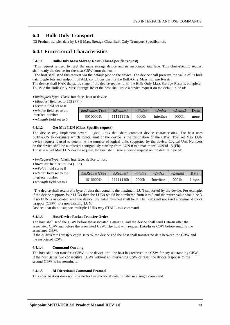
Spinpoint M9TU-USB 3.0 Product Manual REV 1.0 73
USB INTERFACE AND USB COMMANDS
6.4 Bulk-Only Transport N2 Product transfer data by USB Mass Storage Class Bulk Only Transport Specification.
6.4.1 Functional Characteristics
6.4.1.1 Bulk-Only Mass Storage Reset (Class-Specific request) This request is used to reset the mass storage device and its associated interface. This class-specific request
shall ready the device for the next CBW from the host. The host shall send this request via the default pipe to the device. The device shall preserve the value of its bulk
data toggle bits and endpoint STALL conditions despite the Bulk-Only Mass Storage Reset. The device shall NAK the status stage of the device request until the Bulk-Only Mass Storage Reset is complete. To issue the Bulk-Only Mass Storage Reset the host shall issue a device request on the default pipe of:
• bmRequestType: Class, Interface, host to device • bRequest field set to 255 (FFh) • wValue field set to 0 • wIndex field set to the interface number • wLength field set to 0
6.4.1.2 Get Max LUN (Class-Specific request) The device may implement several logical units that share common device characteristics. The host uses bCBWLUN to designate which logical unit of the device is the destination of the CBW. The Get Max LUN device request is used to determine the number of logical units supported by the device. Logical Unit Numbers on the device shall be numbered contiguously starting from LUN 0 to a maximum LUN of 15 (Fh). To issue a Get Max LUN device request, the host shall issue a device request on the default pipe of: • bmRequestType: Class, Interface, device to host • bRequest field set to 254 (FEh) • wValue field set to 0 • wIndex field set to the interface number • wLength field set to 1
The device shall return one byte of data that contains the maximum LUN supported by the device. For example,
if the device supports four LUNs then the LUNs would be numbered from 0 to 3 and the return value would be 3. If no LUN is associated with the device, the value returned shall be 0. The host shall not send a command block wrapper (CBW) to a non-existing LUN. Devices that do not support multiple LUNs may STALL this command.
6.4.1.3 Host/Device Packet Transfer Order The host shall send the CBW before the associated Data-Out, and the device shall send Data-In after the associated CBW and before the associated CSW. The host may request Data-In or CSW before sending the associated CBW. If the dCBWDataTransferLength is zero, the device and the host shall transfer no data between the CBW and the associated CSW.
6.4.1.4 Command Queuing The host shall not transfer a CBW to the device until the host has received the CSW for any outstanding CBW. If the host issues two consecutive CBWs without an intervening CSW or reset, the device response to the second CBW is indeterminate.
6.4.1.5 Bi-Directional Command Protocol This specification does not provide for bi-directional data transfer in a single command.
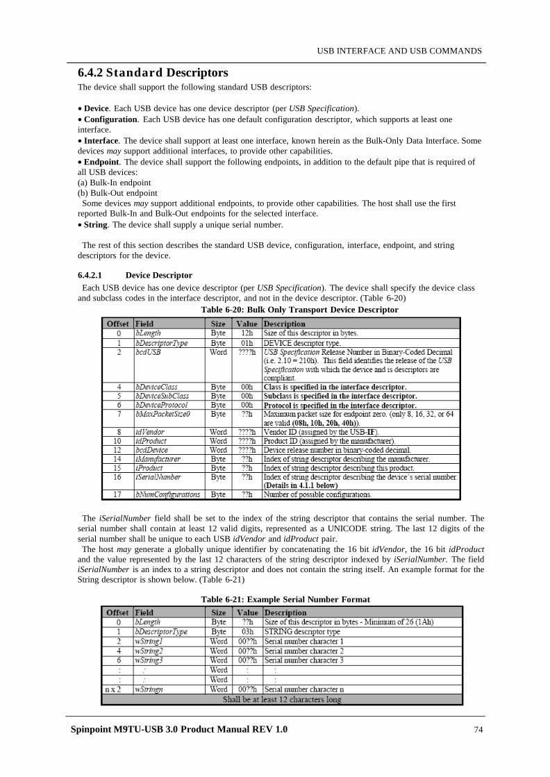
Spinpoint M9TU-USB 3.0 Product Manual REV 1.0 74
USB INTERFACE AND USB COMMANDS
6.4.2 Standard Descriptors The device shall support the following standard USB descriptors:
• Device. Each USB device has one device descriptor (per USB Specification). • Configuration. Each USB device has one default configuration descriptor, which supports at least one interface. • Interface. The device shall support at least one interface, known herein as the Bulk-Only Data Interface. Some devices may support additional interfaces, to provide other capabilities. • Endpoint. The device shall support the following endpoints, in addition to the default pipe that is required of all USB devices: (a) Bulk-In endpoint (b) Bulk-Out endpoint
Some devices may support additional endpoints, to provide other capabilities. The host shall use the first reported Bulk-In and Bulk-Out endpoints for the selected interface. • String. The device shall supply a unique serial number.
The rest of this section describes the standard USB device, configuration, interface, endpoint, and string
descriptors for the device.
6.4.2.1 Device Descriptor Each USB device has one device descriptor (per USB Specification). The device shall specify the device class
and subclass codes in the interface descriptor, and not in the device descriptor. (Table 6-20)
Table 6-20: Bulk Only Transport Device Descriptor
The iSerialNumber field shall be set to the index of the string descriptor that contains the serial number. The
serial number shall contain at least 12 valid digits, represented as a UNICODE string. The last 12 digits of the serial number shall be unique to each USB idVendor and idProduct pair. The host may generate a globally unique identifier by concatenating the 16 bit idVendor, the 16 bit idProduct
and the value represented by the last 12 characters of the string descriptor indexed by iSerialNumber. The field iSerialNumber is an index to a string descriptor and does not contain the string itself. An example format for the String descriptor is shown below. (Table 6-21)
Table 6-21: Example Serial Number Format
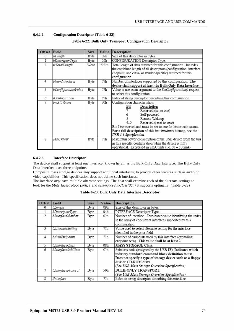
Spinpoint M9TU-USB 3.0 Product Manual REV 1.0 75
USB INTERFACE AND USB COMMANDS
6.4.2.2 Configuration Descriptor (Table 6-22)
Table 6-22: Bulk Only Transport Configuration Descriptor
6.4.2.3 Interface Descriptor The device shall support at least one interface, known herein as the Bulk-Only Data Interface. The Bulk-Only Data Interface uses three endpoints. Composite mass storage devices may support additional interfaces, to provide other features such as audio or video capabilities. This specification does not define such interfaces. The interface may have multiple alternate settings. The host shall examine each of the alternate settings to look for the bInterfaceProtoco (50h) l and bInterfaceSubClass(06h) it supports optimally. (Table 6-23)
Table 6-23: Bulk Only Data Interface Descriptor
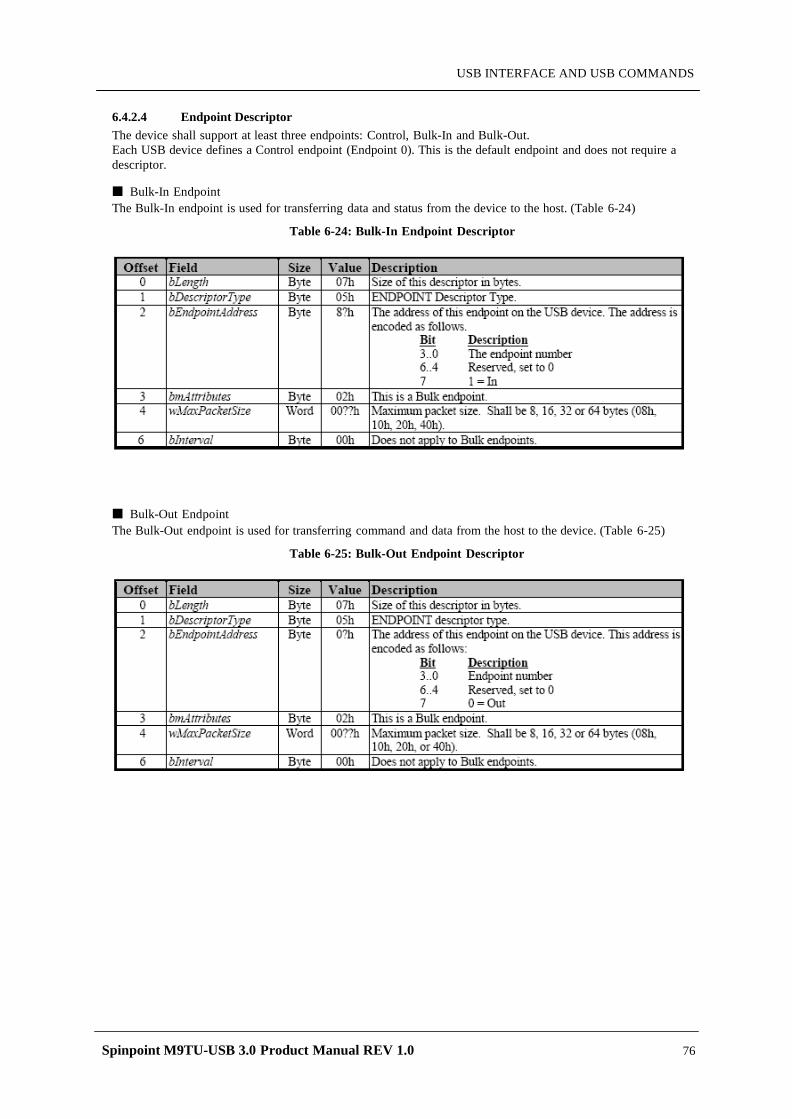
Spinpoint M9TU-USB 3.0 Product Manual REV 1.0 76
USB INTERFACE AND USB COMMANDS
6.4.2.4 Endpoint Descriptor The device shall support at least three endpoints: Control, Bulk-In and Bulk-Out. Each USB device defines a Control endpoint (Endpoint 0). This is the default endpoint and does not require a descriptor.
Bulk-In Endpoint The Bulk-In endpoint is used for transferring data and status from the device to the host. (Table 6-24)
Table 6-24: Bulk-In Endpoint Descriptor
Bulk-Out Endpoint The Bulk-Out endpoint is used for transferring command and data from the host to the device. (Table 6-25)
Table 6-25: Bulk-Out Endpoint Descriptor
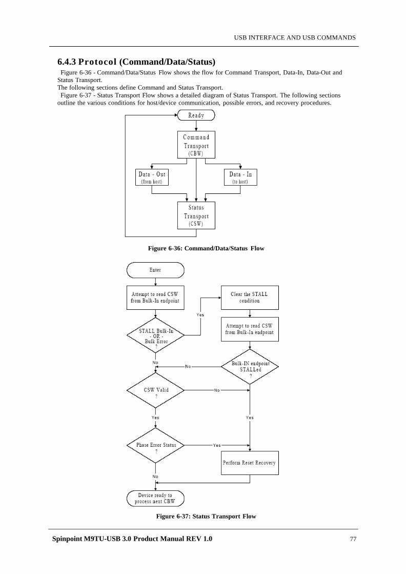
Spinpoint M9TU-USB 3.0 Product Manual REV 1.0 77
USB INTERFACE AND USB COMMANDS
6.4.3 Protocol (Command/Data/Status) Figure 6-36 - Command/Data/Status Flow shows the flow for Command Transport, Data-In, Data-Out and
Status Transport. The following sections define Command and Status Transport. Figure 6-37 - Status Transport Flow shows a detailed diagram of Status Transport. The following sections
outline the various conditions for host/device communication, possible errors, and recovery procedures.
Figure 6-36: Command/Data/Status Flow
Figure 6-37: Status Transport Flow
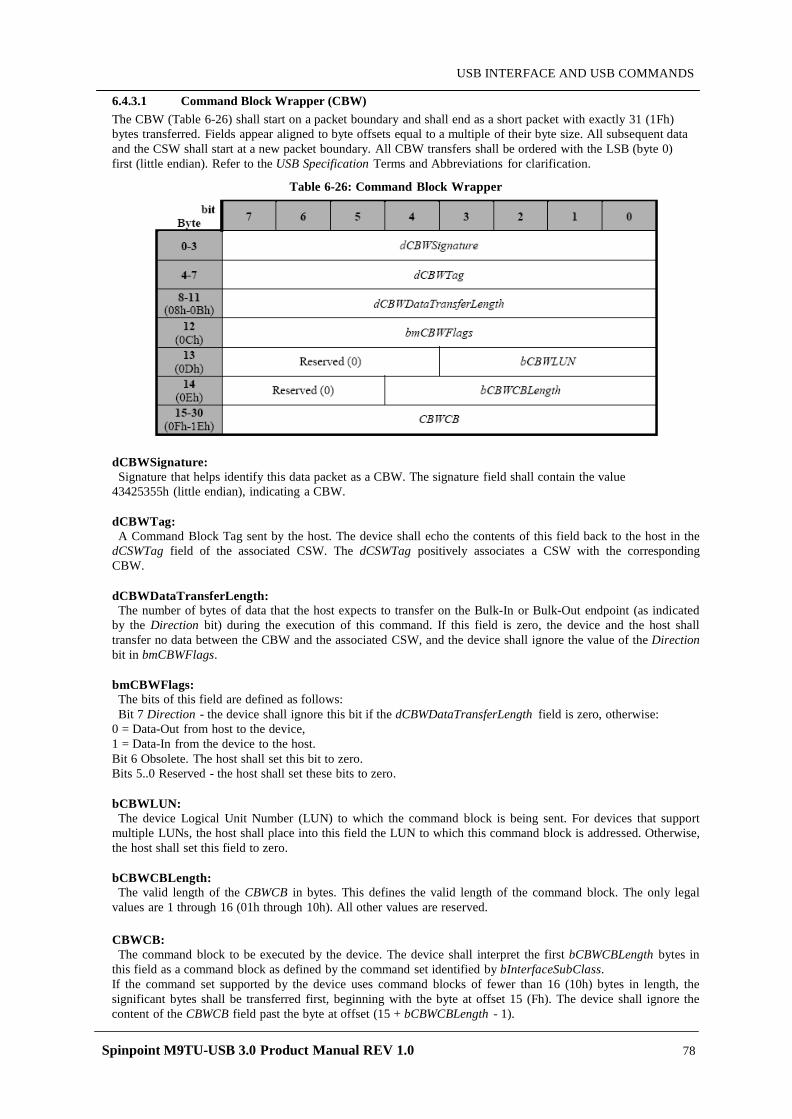
Spinpoint M9TU-USB 3.0 Product Manual REV 1.0 78
USB INTERFACE AND USB COMMANDS
6.4.3.1 Command Block Wrapper (CBW) The CBW (Table 6-26) shall start on a packet boundary and shall end as a short packet with exactly 31 (1Fh) bytes transferred. Fields appear aligned to byte offsets equal to a multiple of their byte size. All subsequent data and the CSW shall start at a new packet boundary. All CBW transfers shall be ordered with the LSB (byte 0) first (little endian). Refer to the USB Specification Terms and Abbreviations for clarification.
Table 6-26: Command Block Wrapper
dCBWSignature: Signature that helps identify this data packet as a CBW. The signature field shall contain the value
43425355h (little endian), indicating a CBW.
dCBWTag: A Command Block Tag sent by the host. The device shall echo the contents of this field back to the host in the
dCSWTag field of the associated CSW. The dCSWTag positively associates a CSW with the corresponding CBW.
dCBWDataTransferLength: The number of bytes of data that the host expects to transfer on the Bulk-In or Bulk-Out endpoint (as indicated
by the Direction bit) during the execution of this command. If this field is zero, the device and the host shall transfer no data between the CBW and the associated CSW, and the device shall ignore the value of the Direction bit in bmCBWFlags.
bmCBWFlags: The bits of this field are defined as follows: Bit 7 Direction - the device shall ignore this bit if the dCBWDataTransferLength field is zero, otherwise:
0 = Data-Out from host to the device, 1 = Data-In from the device to the host. Bit 6 Obsolete. The host shall set this bit to zero. Bits 5..0 Reserved - the host shall set these bits to zero.
bCBWLUN: The device Logical Unit Number (LUN) to which the command block is being sent. For devices that support
multiple LUNs, the host shall place into this field the LUN to which this command block is addressed. Otherwise, the host shall set this field to zero.
bCBWCBLength: The valid length of the CBWCB in bytes. This defines the valid length of the command block. The only legal
values are 1 through 16 (01h through 10h). All other values are reserved. CBWCB: The command block to be executed by the device. The device shall interpret the first bCBWCBLength bytes in
this field as a command block as defined by the command set identified by bInterfaceSubClass. If the command set supported by the device uses command blocks of fewer than 16 (10h) bytes in length, the significant bytes shall be transferred first, beginning with the byte at offset 15 (Fh). The device shall ignore the content of the CBWCB field past the byte at offset (15 + bCBWCBLength - 1).
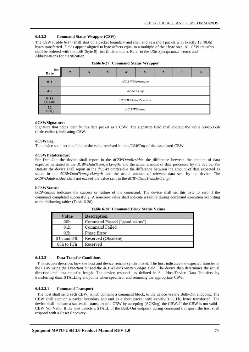
Spinpoint M9TU-USB 3.0 Product Manual REV 1.0 79
USB INTERFACE AND USB COMMANDS
6.4.3.2 Command Status Wrapper (CSW) The CSW (Table 6-27) shall start on a packet boundary and shall end as a short packet with exactly 13 (0Dh) bytes transferred. Fields appear aligned to byte offsets equal to a multiple of their byte size. All CSW transfers shall be ordered with the LSB (byte 0) first (little endian). Refer to the USB Specification Terms and Abbreviations for clarification.
Table 6-27: Command Status Wrapper
dCSWSignature: Signature that helps identify this data packet as a CSW. The signature field shall contain the value 53425355h (little endian), indicating CSW.
dCSWTag: The device shall set this field to the value received in the dCBWTag of the associated CBW.
dCSWDataResidue: For Data-Out the device shall report in the dCSWDataResidue the difference between the amount of data expected as stated in the dCBWDataTransferLength, and the actual amount of data processed by the device. For Data-In the device shall report in the dCSWDataResidue the difference between the amount of data expected as stated in the dCBWDataTransferLength and the actual amount of relevant data sent by the device. The dCSWDataResidue shall not exceed the value sent in the dCBWDataTransferLength.
bCSWStatus: bCSWStatus indicates the success or failure of the command. The device shall set this byte to zero if the command completed successfully. A non-zero value shall indicate a failure during command execution according to the following table: (Table 6-28)
Table 6-28: Command Block Status Values
6.4.3.3 Data Transfer Conditions This section describes how the host and device remain synchronized. The host indicates the expected transfer in
the CBW using the Direction bit and the dCBWDataTransferLength field. The device then determines the actual direction and data transfer length. The device responds as defined in 6 - Host/Device Data Transfers by transferring data, STALLing endpoints when specified, and returning the appropriate CSW.
6.4.3.3.1 Command Transport The host shall send each CBW, which contains a command block, to the device via the Bulk-Out endpoint. The
CBW shall start on a packet boundary and end as a short packet with exactly 31 (1Fh) bytes transferred. The device shall indicate a successful transport of a CBW by accepting (ACKing) the CBW. If the CBW is not valid - CBW Not Valid. If the host detects a STALL of the Bulk-Out endpoint during command transport, the host shall respond with a Reset Recovery.
Spinpoint M9TU-USB 3.0 Product Manual REV 1.0 80
USB INTERFACE AND USB COMMANDS
6.4.3.3.2 Data Transport All data transport shall begin on a packet boundary. The host shall attempt to transfer the exact number of bytes to or from the device as specified by the dCBWDataTransferLength and the Direction bit. The device shall respond as specified in 6 - Host/Device Data Transfers. To report an error before data transport completes and to maximize data integrity, the device may terminate the command by STALLing the endpoint in use (the Bulk-In endpoint during data in, the Bulk-Out endpoint during data out).
6.4.3.3.3 Status Transport The device shall send each CSW to the host via the Bulk-In endpoint. The CSW shall start on a packet boundary and end as a short packet with exactly 13 (Dh) bytes transferred. Figure 6-36 - Status Transport Flow defines the algorithm the host shall use for any CSW transfer. The CSW indicates to the host the status of the execution of the command block from the corresponding CBW. The dCSWDataResidue field indicates how much of the data transferred is to be considered processed or relevant. The host shall ignore any data received beyond that which is relevant.
6.4.3.3.4 Phase Error The host shall perform a Reset Recovery when Phase Error status is returned in the CSW.
6.4.3.3.5 Reset Recovery For Reset Recovery the host shall issue in the following order: (a) a Bulk-Only Mass Storage Reset (b) a Clear Feature HALT to the Bulk-In endpoint (c) a Clear Feature HALT to the Bulk-Out endpoint
6.4.4 Host/Device Data Transfers
6.4.4.1 Overview A Bulk-Only Protocol transaction begins with the host sending a CBW to the device and attempting to make the appropriate data transfer (In, Out or none). The device receives the CBW, checks and interprets it, attempts to satisfy the host's request, and returns status via a CSW. This section describes in more detail this interaction between the host and the device during normal and abnormal Bulk-Only Protocol transactions.
6.4.4.2 Valid and Meaningful CBW The host communicates its intent to the device through the CBW. The device performs two verifications on every CBW received. First, the device verifies that what was received is a valid CBW. Next, the device determines if the data within the CBW is meaningful. The device shall not use the contents of the dCBWTag in any way other than to copy its value to the dCSWTag of the corresponding CSW.
Valid CBW The device shall consider the CBW valid when: • The CBW was received after the device had sent a CSW or after a reset, • the CBW is 31 (1Fh) bytes in length, • and the dCBWSignature is equal to 43425355h.
Meaningful CBW The device shall consider the contents of a valid CBW meaningful when: • no reserved bits are set, • the bCBWLUN contains a valid LUN supported by the device, • and both bCBWCBLength and the content of the CBWCB are in accordance with bInterfaceSubClass.
Spinpoint M9TU-USB 3.0 Product Manual REV 1.0 81
USB INTERFACE AND USB COMMANDS
6.4.4.3 Valid and Meaningful CSW The device generally communicates the results of its attempt to satisfy the host’s request through the CSW. The host performs two verifications on every CSW received. First, the host verifies that what was received is a valid CSW Next, the host determines if the data within the CSW is meaningful.
Valid CSW The host shall consider the CSW valid when: • the CSW is 13 (Dh) bytes in length, • and the dCSWSignature is equal to 53425355h, • the dCSWTag matches the dCBWTag from the corresponding CBW.
Meaningful CSW The host shall consider the contents of the CSW meaningful when: either the bCSWStatus value is 00h or 01h and the dCSWDataResidue is less than or equal to dCBWDataTransferLength.. or the bCSWStatus value is 02h.
6.4.4.4 Device Error Handling The device may not be able to fully satisfy the host's request. At the point when the device discovers that it
cannot fully satisfy the request, there may be a Data-In or Data-Out transfer in progress on the bus, and the host may have other pending requests. The device may cause the host to terminate such transfers by STALLing the appropriate pipe. The response of a device to a CBW that is not meaningful is not specified. Please note that whether or not a STALL handshake actually appears on the bus depends on whether or not there is a transfer in progress at the point in time when the device is ready to STALL the pipe.
6.4.4.5 Host Error Handling If the host receives a CSW which is not valid, then the host shall perform a Reset Recovery. If the host receives
a CSW which is not meaningful, then the host may perform a Reset Recovery.
6.4.4.6 Error Classes In every transaction between the host and the device, there are four possible classes of errors. These classes are
not always independent of each other and may occur at any time during the transaction.
6.4.4.6.1 CBW Not Valid If the CBW is not valid, the device shall STALL the Bulk-In pipe. Also, the device shall either STALL the
Bulk-Out pipe, or the device shall accept and discard any Bulk-Out data. The device shall maintain this state until a Reset Recovery.
6.4.4.6.2 Internal Device Error The device may detect an internal error for which it has no reliable means of recovery other than a reset. The
device shall respond to such conditions by: either STALLing any data transfer in progress and returning a Phase Error status (bCSWStatus = 02h). or STALLing all further requests on the Bulk-In and the Bulk-Out pipes until a Reset Recovery.
6.4.4.6.3 Host/Device Disagreements After recognizing that a CBW is valid and meaningful, and in the absence of internal errors, the device may
detect a condition where it cannot meet the host’s expectation for data transfer, as indicated by the Direction bit of the bmCBWFlags field and the dCBWDataTransferLength field of the CBW. In some of these cases, the device may require a reset to recover. In these cases, the device shall return Phase Error status (bCSWStatus = 02h).
6.4.4.6.4 Command Failure After recognizing that a CBW is valid and meaningful, the device may still fail in its attempt to satisfy the
command. The device shall report this condition by returning a Command Failed status (bCSWStatus = 01h).
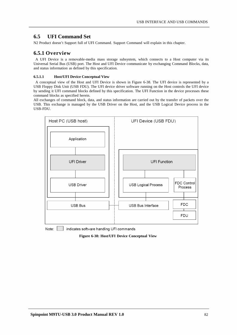
Spinpoint M9TU-USB 3.0 Product Manual REV 1.0 82
USB INTERFACE AND USB COMMANDS
6.5 UFI Command Set N2 Product doesn’t Support full of UFI Command. Support Command will explain in this chapter.
6.5.1 Overview A UFI Device is a removable-media mass storage subsystem, which connects to a Host computer via its
Universal Serial Bus (USB) port. The Host and UFI Device communicate by exchanging Command Blocks, data, and status information as defined by this specification.
6.5.1.1 Host/UFI Device Conceptual View A conceptual view of the Host and UFI Device is shown in Figure 6-38. The UFI device is represented by a
USB Floppy Disk Unit (USB FDU). The UFI device driver software running on the Host controls the UFI device by sending it UFI command blocks defined by this specification. The UFI Function in the device processes these command blocks as specified herein. All exchanges of command block, data, and status information are carried out by the transfer of packets over the USB. This exchange is managed by the USB Driver on the Host, and the USB Logical Device process in the USB-FDU.
Figure 6-38: Host/UFI Device Conceptual View
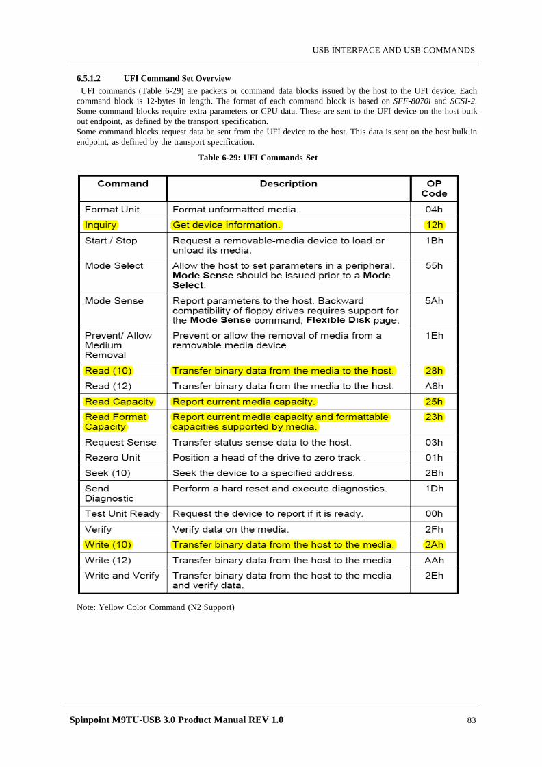
Spinpoint M9TU-USB 3.0 Product Manual REV 1.0 83
USB INTERFACE AND USB COMMANDS
6.5.1.2 UFI Command Set Overview UFI commands (Table 6-29) are packets or command data blocks issued by the host to the UFI device. Each
command block is 12-bytes in length. The format of each command block is based on SFF-8070i and SCSI-2. Some command blocks require extra parameters or CPU data. These are sent to the UFI device on the host bulk out endpoint, as defined by the transport specification. Some command blocks request data be sent from the UFI device to the host. This data is sent on the host bulk in endpoint, as defined by the transport specification.
Table 6-29: UFI Commands Set
Note: Yellow Color Command (N2 Support)
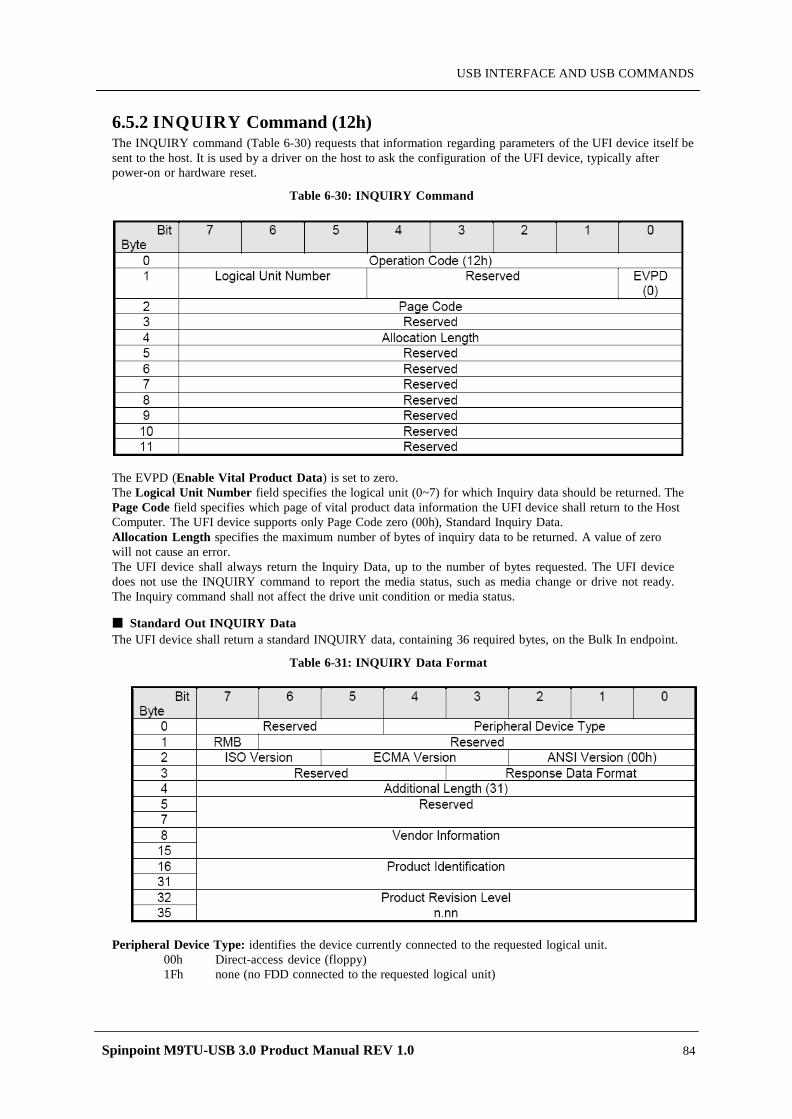
Spinpoint M9TU-USB 3.0 Product Manual REV 1.0 84
USB INTERFACE AND USB COMMANDS
6.5.2 INQUIRY Command (12h) The INQUIRY command (Table 6-30) requests that information regarding parameters of the UFI device itself be sent to the host. It is used by a driver on the host to ask the configuration of the UFI device, typically after power-on or hardware reset.
Table 6-30: INQUIRY Command
The EVPD (Enable Vital Product Data) is set to zero. The Logical Unit Number field specifies the logical unit (0~7) for which Inquiry data should be returned. The Page Code field specifies which page of vital product data information the UFI device shall return to the Host Computer. The UFI device supports only Page Code zero (00h), Standard Inquiry Data. Allocation Length specifies the maximum number of bytes of inquiry data to be returned. A value of zero will not cause an error. The UFI device shall always return the Inquiry Data, up to the number of bytes requested. The UFI device does not use the INQUIRY command to report the media status, such as media change or drive not ready. The Inquiry command shall not affect the drive unit condition or media status.
Standard Out INQUIRY Data The UFI device shall return a standard INQUIRY data, containing 36 required bytes, on the Bulk In endpoint.
Table 6-31: INQUIRY Data Format
Peripheral Device Type: identifies the device currently connected to the requested logical unit.
00h Direct-access device (floppy) 1Fh none (no FDD connected to the requested logical unit)

Spinpoint M9TU-USB 3.0 Product Manual REV 1.0 85
USB INTERFACE AND USB COMMANDS
RMB: Removable Media Bit: this shall be set to one to indicate removable media. ISO/ECMA: These fields shall be zero for the UFI device. ANSI Version: must contain a zero to comply with this version of the Specification. Response Data Format: a value of 01h shall be used for UFI device The Additional Length field shall specify the length in bytes of the parameters. If the Allocation Length of the Command Packet is too small to transfer all of the parameters, the Additional Length shall not be adjusted to reflect the truncation. The UFI device shall set this field to 1Fh. The Vendor Identification field contains 8 bytes of ASCII data identifying the vendor of the product. The data shall be left aligned within this field. The Product Identification field contains 16 bytes of ASCII data as defined by the vendor. The data shall be left-aligned within this field. The Product Revision Level field contains 4 bytes of ASCII data as defined by the vendor. The data shall be left-aligned within this field. For a UFI device, this field indicates the firmware revision number.
6.5.3 READ (10) Command (28h) The READ (10) command (Table 6-32) requests that the UFI device transfer data to the host. The most recent data value written in the addressed logical block shall be returned.
Table 6-32: READ (10) Command
DPO: This bit should be set to zero. FUA: This bit should be set zero. RelAdr: This bit should be set to zero.
6.5.4 READ CAPACITY Command (25h) The READ CAPACITIY command (Table 6-33) allows the host to request capacities of the currently installed medium.
Table 6-33: READ CAPACITY Command
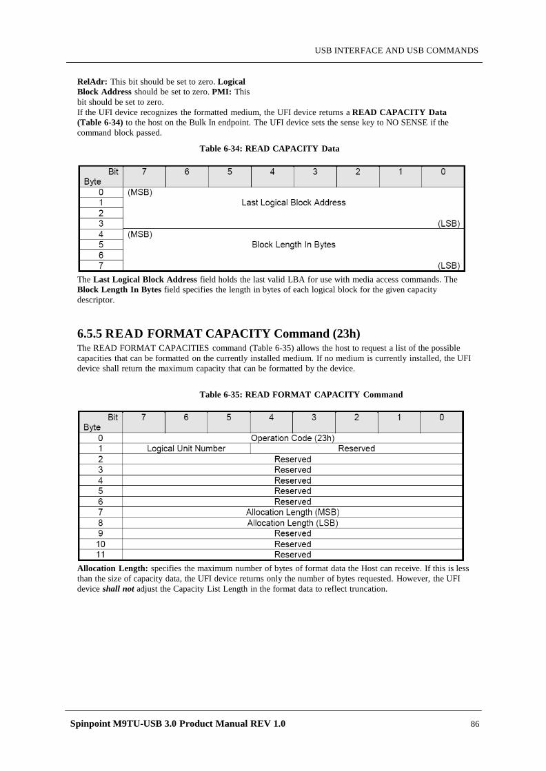
Spinpoint M9TU-USB 3.0 Product Manual REV 1.0 86
USB INTERFACE AND USB COMMANDS
RelAdr: This bit should be set to zero. Logical Block Address should be set to zero. PMI: This bit should be set to zero. If the UFI device recognizes the formatted medium, the UFI device returns a READ CAPACITY Data (Table 6-34) to the host on the Bulk In endpoint. The UFI device sets the sense key to NO SENSE if the command block passed.
Table 6-34: READ CAPACITY Data
The Last Logical Block Address field holds the last valid LBA for use with media access commands. The Block Length In Bytes field specifies the length in bytes of each logical block for the given capacity descriptor.
6.5.5 READ FORMAT CAPACITY Command (23h) The READ FORMAT CAPACITIES command (Table 6-35) allows the host to request a list of the possible capacities that can be formatted on the currently installed medium. If no medium is currently installed, the UFI device shall return the maximum capacity that can be formatted by the device.
Table 6-35: READ FORMAT CAPACITY Command
Allocation Length: specifies the maximum number of bytes of format data the Host can receive. If this is less than the size of capacity data, the UFI device returns only the number of bytes requested. However, the UFI device shall not adjust the Capacity List Length in the format data to reflect truncation.

Spinpoint M9TU-USB 3.0 Product Manual REV 1.0 87
USB INTERFACE AND USB COMMANDS
6.5.5.1 Capacity List Upon receipt of this command block, the UFI device returns a Capacity List (Table 6-36) to the host on the Bulk In endpoint. - No media in FDU: Capacity List Header + Maximum Capacity Header - Media in FDU: Capacity List Header + Current Capacity Header + Formattable Capacity Descriptors
Table 6-36: Capacity List
The Capacity List Header (Table 6-37) gives the length of the descriptor data to follow.
Table 6-37: Capacity List Header
The Capacity List Length field specifies the length in bytes of the Capacity Descriptors that follow. Each Capacity Descriptor is eight bytes in length, making the Capacity List Length equal to eight times the number of descriptors. The Current/Maximum Capacity Descriptor (Table 6-38) describes the current medium capacity if media is mounted in the UFI device and the format is known, else the maximum capacity that can be formatted by the UFI device if no media is mounted, or if the mounted media is unformatted, or if the format of the mounted media is unknown.
Table 6-38: Current/Maximum Capacity Descriptor
The Number of Blocks field indicates the total number of addressable blocks for the descriptor’s media type. The Descriptor Code (Table 6-39) field specifies the type of descriptor returned to the Host.

Spinpoint M9TU-USB 3.0 Product Manual REV 1.0 88
USB INTERFACE AND USB COMMANDS
Table 6-39: Descriptor Code Definition
Table 6-40: Formattable Capacity Descriptor
The Number of Blocks field indicates the maximum (or fixed) number of addressable blocks for the given capacity descriptor. The Block Length specifies the length in bytes of each logical block for the given capacity descriptor.
6.5.6 WRITE (10) Command (2Ah) The WRITE (10) command (Table 6-41) requests that the UFI device write the data transferred by the host to the medium.
Table 6-41: WRITE (10) Command
DPO: This bit should be set to zero. FUA: This bit should be set to zero. RelAdr: This bit should be set to zero.
Spinpoint M9TU-USB 3.0 Product Manual REV 1.0 89
MAINTENANCE
CHAPTER 7 MAINTENANCE
7.1 General Information
Seagate's Spinpoint M9TU-USB 3.0 hard disk drive achieves high reliability through their mechanical design and extensive use of microelectronics. Their design allows fast, easy sub-assembly r e p l a c e m e n t w i t h o u t adjustments, greatly reducing the amount of downtime required for unscheduled repairs.
7.2 Maintenance Precautions
When servicing a drive, the service technician should observe the following precautions to avoid damage to the drive or personal injury.
(1) Do not attempt to open the sealed compartment of the Spinpoint M9TU-USB 3.0 hard disk
drive, as this will void the warranty and contaminate the media.
(2) Do not lift the Spinpoint M9TU-USB 3.0 hard disk drive by the PCB.
(3) Please handle HDD by side surfaces Please see the Fig. 9-1
(4) Avoid static discharge when handling the Spinpoint M9TU-USB 3.0 hard disk drive.
(5) Do not touch cover and the components on the PCB. Please see the Fig. 9-2
(6) Do not stack the HDDs in column
Please see the Fig. 9-3
(7) Avoid harsh shocks or vibration to the drive at all times. Please see the Fig. 9-4
(8) Observe the environmental limits specified for this product, as listed in section 3.6.
(9) If it becomes necessary to move your computer system, turn off the power to automatically
park the heads. Parking the heads moves the heads to a safe, non-data landing zone and locks the heads in place. This helps prevent the media and the heads from accidental damage due to vibration, moving or shipping. Do not move the drive for 20 seconds after removing DC power to ensure that the actuator is completely locked.
Back up your data regularly. Seagate assumes no responsibility for loss of data. For information about back- up and restore procedures, consult your DOS manual. There are also a number of utility programs available that you can use to back up your data.
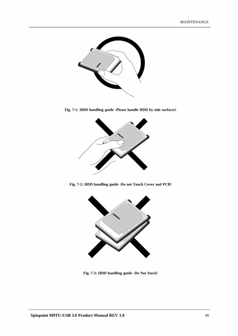
Spinpoint M9TU-USB 3.0 Product Manual REV 1.0 90
MAINTENANCE
Fig. 7-1: HDD handling guide -Please handle HDD by side surfaces!
Fig. 7-2: HDD handling guide -Do not Touch Cover and PCB!
Fig. 7-3: HDD handling guide -Do Not Stack!
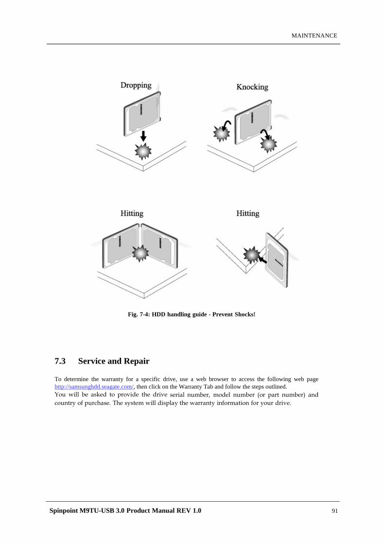
Spinpoint M9TU-USB 3.0 Product Manual REV 1.0 91
MAINTENANCE
Fig. 7-4: HDD handling guide - Prevent Shocks!
7.3 Service and Repair
To determine the warranty for a specific drive, use a web browser to access the following web page http://samsunghdd.seagate.com/, then click on the Warranty Tab and follow the steps outlined. You will be asked to provide the drive serial number, model number (or part number) and country of purchase. The system will display the warranty information for your drive.