Embed Size (px)
Citation preview

M9310/VA9310 Series
Electric Non-Spring Return Actuators

3
FEATURES BENEFITS
Automatic Signal Input Detection, On/Off, Floating,
and Proportional Control with Adjustable Span and
Offset
Increases availability at distributors and simplifies retrofits.
Easy Conversion to Valve Operation - Same Actuator
Used for Dampers or ValvesIncreases availability at distributors with only one actuator to learn.
Optional Accessory Kit
Increases availability at distributors. The auxiliary switch kit provides two line-voltage-capable single-pole, double-throw (SPDT) switches with continuously adjustable switch points, and the auxiliary potentiometer kit provides several potentiometer feedback options. Facilitates safety interfacing or signaling.
Backward Compatible Auxiliary Switch Kits and
Auxiliary PotentiometerAllows for a seamless retrofit without the need to replace the controller.
88 lb·in (10 N·m) Rated TorqueProvides high torque in a compact package size to expand the range of applications in HVAC systems.
Self-Calibrating Input Signal to Adjust StrokeEliminates the need for a complex calibration procedure when adjusting stops.
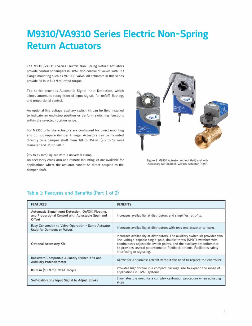
M9310/VA9310 Series Electric Non-Spring
Return Actuators
The M9310/VA9310 Series Electric Non-Spring Return Actuators provide control of dampers in HVAC also control of valves with ISO Flange mounting such as VG1000 valve. All actuators in this series provide 88 lb·in (10 N·m) rated torque.
The series provides Automatic Signal Input Detection, which allows automatic recognition of input signals for on/off, floating, and proportional control.
An optional line voltage auxiliary switch kit can be field installed to indicate an end-stop position or perform switching functions within the selected rotation range. For M9310 only, the actuators are configured for direct mounting and do not require damper linkage. Actuators can be mounted directly to a damper shaft from 3/8 to 3/4 in. (9.5 to 19 mm) diameter and 3/8 to 5/8 in.
(9.5 to 15 mm) square with a universal clamp.An accessory crank arm and remote mounting kit are available for applications where the actuator cannot be direct-coupled to the damper shaft.
Table 1: Features and Benefits (Part 1 of 2)
Figure 1: M9310 Actuator without (left) and with Accessory Kit (middle), VA9310 Actuator (right)

4
FEATURES BENEFITS
Electronic Stall Detection
Protects from overload at all angles of rotation. The actuator may be stalled anywhere in its rotation range without the need for mechanical end switches.
Microprocessor-Controlled Brushless DC MotorProvides constant runtime independent of torque and increases lifecycle by reducing wear.
Mode Configuration SwitchesPermits calibration, input signal range selection, and control logic reversal for proportional control.
Integral Cables with Colored and Numbered
ConductorsSimplify installation and field wiring.
Small FootprintAllows application in smaller spaces than the M9106/M9109 and M9108 actuators.
M9106, M9109, and M9108 Series Actuators
ReplacementSimplifies product selection and logistics.
100,000 Cycles and 2.5 Million Repositions Assure long time reliability.
NEMA5/IP54 Enclosure Enhances the range of application environments.
Underwriters Laboratories Inc.® (UL), CE Mark, and
RCM ComplianceProvides internationally recognized regulatory agency approvals.
Manufactured under International Standards
Organization (ISO) 9001 Quality Control StandardsEnsures quality.
Position Indicator Handle (VA9310) Allows intuitive indication of valve position
Bottom-Mounted Coupler (M9310) Simplifies short shaft damper applications.
Same Weathershield as M9203 and M9208 Series
ActuatorsKeeps logistics simple and assures quick delivery time.
5-Year Warranty Protects consumer investment.
Table 1: Features and Benefits (Part 2 of 2)
Product Details
M9310/VA9310 Series Actuators operate with 24 VAC/DC to provide 88 lb·in. (10 N·m) rated torque. The actuators can be used with on/off, floating, or proportional controllers in HVAC systems that are controlled by an electronic controller or positioner.
Floating control is provided from a triac or relay. On/off control can be provided from a manual switch, controller, auxiliary switch from a fan motor contactor, or similar device.
The actuators have 90-second constant runtime for 90° rotation, independent of supply voltage frequency and load.
When the M9310/VA9310 Series Actuators are in proportional mode, the actuator responds to 0 to 10 VDC or 2 to 10 VDC
control signals. With the addition of a 500 ohm resistor, the actuator responds to a 0 to 20 mA or 4 to 20 mA signal. A 0 to 10 VDC or 2 to 10 VDC feedback signal indicates position.

5
M9310/VA9310-HGA-3 Actuators Wiring Diagrams
IMPORTANT: Use these M9310 Series Electric Non-Spring Return Actuators only to control equipment under normal operating conditions. Where failure or malfunction of the electric actuator could lead to personal injury or property damage to the controlled equipment or other property, additional precautions must be designed into the control system. Incorporate and maintain other devices, such as supervisory or alarm systems or safety or limit controls, intended to warn of or protect against failure or malfunction of the electric actuator.
RED
RED
RED
RED
GRY
GRY
GRY
GRY
BLK
BLK
BLK
BLK
COM
COM
COM
COM
500 ohm, 1.4 W
OR
N
OR
NO
RN
OR
N (
+)
0
to 1
0 V
DC
(+)
0
to
10 V
DC
(+)
0
to
10 V
DC
(+)
0
to
10 V
DC
24 V
AC/
DC 24
V A
C/D
C24
V A
C/D
C
24 V
AC/
DC
24 V
AC/
DC
(+)
0
to
10 V
DC
(+
)
0 (4
) to
20
mA
FIG
:Flo
atin
g 24
V A
pplic
atio
ns
FIG
:Pro
port
iona
l 24V
App
licat
ions
FIG
:Con
trol
with
Ext
erna
l Res
isto
r
FIG
:On/
Off
24V
App
licat
ions
Figure 2: Floating 24 V Applications
Figure 3: On/Off 24 V Applications
Figure 4: Proportional 24 V Applications
Figure 5: Proportional 24 V Applications - 0 (4) to 20 mA with External Resistor

6
Mounting Options
Operation
Auto-Calibration Mode
DIP Switches and Status LEDs
M9310 Series Damper Actuators can be converted into VA9310 Series Valve Actuators using the M9310-500 valve linkage.
VA9310 Series Actuators are mounted directly to the valve or with the M9000-561 thermal barrier when the high temperature fluid or low pressure steam are used or additional spacing for insulation is needed.
VA9310 Series Actuators can be easily converted into M9310 Series Actuators using the M9310-600 coupler.
M9310/VA9310 Series Actuators use a brushless DC motor controlled by a microprocessor. The microprocessor drives the motor at constant speed, independent of torque. The actuator slows down before it reaches its stop position allowing it to coast, further reducing gear wear. The microprocessor also monitors the brushless DC motor’s rotation to prevent damage to the actuator in a stall condition. The actuator can be stalled anywhere within its rotation range without the need for mechanical end switches.
The actuator self-calibrates the control signal when an end stop is adjusted on the stroke. An auto-calibration has to be performed to change the feedback of the actuator.
The auto-calibration mode identifies the available range of travel of the coupler. During the auto-calibration mode, the actuator moves the coupler to the maximum and minimum end stops to identify the range of travel.
The actuators allow easy setting of the proportional input signals. See the installation instruction for details.

7
Ordering Information
1. Feedback is only available when 0 (2) to 10 V proportional input is used.2. Order separately M9300-100 (quantity 5).3. Order separately M9300-1 or M9300-2.
Code NumberRotation
Time For 90°Power Requirement Input Signal
Position
Feedback
Electrical
Connection
Auxiliary
SwitchesR
unni
ng (
Seco
nds)
24 V
AC
(19.
2 to
28.
8 VA
C) a
t 50
/60,
Cla
ss 2
(N
orth
Am
eric
a)
or S
ELV
(Eu
rope
), 4.
7 VA
run
ning
.
24 V
DC
(21.
6 to
28.
8 V
DC)
Cla
ss 2
(N
orth
Am
eric
a)
or S
ELV
(Eu
rope
), 1.
3 W
run
ning
.
On/
Off
OnF
loat
ing
0 (2
) to
10
VD
C
Adj
usta
ble
Span
and
Off
set
0 (2
) to
10
VD
C
50 in
. (1.
27m
) 18
AW
G H
alog
en-f
ree
Cabl
e
1/2
in. N
PSM
(13
mm
) Th
read
ed C
ondu
it Co
nnec
tors
1 x
SPD
T or
2 x
SPD
TM9310-HGA-3,VA9310-HGA-3
90 X X X X X X1 X Optional2 Optional3
Table 2: Selection Chart

8
PICTURE CODE NUMBER DESCRIPTION
M9000-322M9310 only
NEMA 4x, IP66/67 Weathershield Kit for damper application of M9104, M9310, M9203, and M9208 Series Electric Actuators
M9000-342VA9310 only
NEMA 4X, IP66/67 Weathershield Kit for VG1000 Series Ball application of VA9104, VA9310, VA9203, andVA9208 Series Electric Actuators (quantity 1)
M9000-561VA9310 only
Thermal Barrier Kit. Extends the VA9104, VA9310, VA9203, and VA9208 Series Electric Actuators applications to include low pressure steam
M9000-604M9310 only
Replacement Anti-Rotation Bracket Kit for M9310, M9203, M9208, M9210, and M9220 Series Electric Actuators
M9000-606M9310 only
Position indicator (quantity 5)
M9300-1 Auxiliary Switch Kit (one single-pole, double-throw)
M9300-2 Auxiliary Switch Kit (two single-pole, double-throw)
M9300-100 Threaded Conduit Adapters for 1/2 in. electrician’s fittings (quantity 5)
M9300-140 External Auxiliary Feedback Potentiometer 140 ohm
M9000-151M9310 only
Remote Mounting Kit, with crank arm and damper linkage for M9108 (16) (24), and M9300 Series Actuators
M9300-1K External Auxiliary Feedback Potentiometer 1k ohm
M9300-2K External Auxiliary Feedback Potentiometer 2k ohm
M9300-10K External Auxiliary Feedback Potentiometer 10k ohm
M9310-500M9310 only
Ball Valve Linkage Kit for converting M9310 actuators to VA9310 actuators for operating VG1000 ball valves
M9310-600Standard Coupler Kit, M9310 Series (round 3/8 to 3/4 in. [9 to 19 mm], square 3/8 to 5/8
in. [9 to 16 mm])
Table 3: Accessories (Order Separately)
9
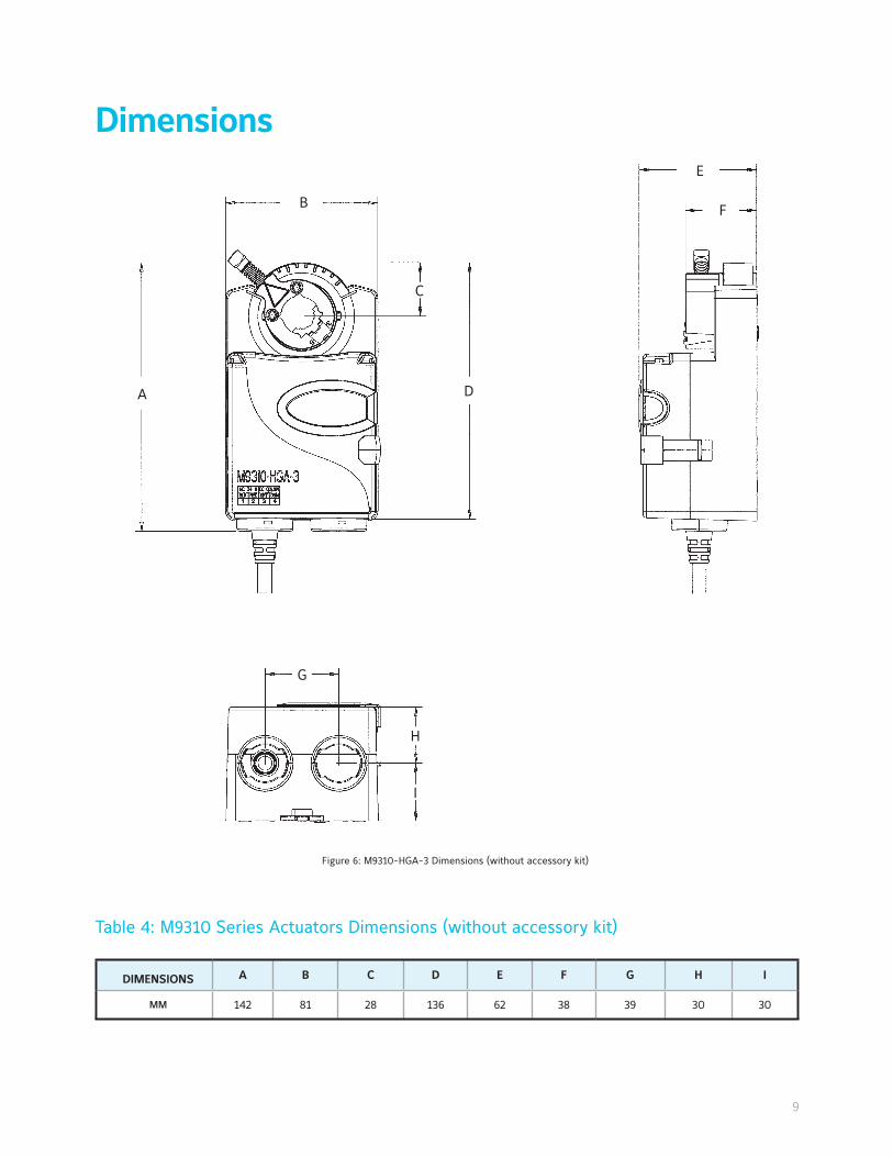
DIMENSIONS A B C D E F G H I
MM 142 81 28 136 62 38 39 30 30
Dimensions
Figure 6: M9310-HGA-3 Dimensions (without accessory kit)
Table 4: M9310 Series Actuators Dimensions (without accessory kit)
A
B
C
D
E
F
G
H
I

10
Figure 7: VA9310 Series Electric Non-Spring Return Actuator and Valve Dimensions (with Optional M9000-561 Thermal Barrier)
Table 5: VA9310 Actuated VG1205, VG1805 Series Ball Valve Dimensions, (mm)
VALVE SIZE
A
(With
Thermal
Barrier)
A
(Without
Thermal
Barrier)
B C D E F G
DN15 146 111 17 31 163 64 9 32
DN20 146 111 17 31 163 71 9 36
DN25 148 113 19 33 163 87 9 43
DN32 159 124 26 44 163 100 9 50
DN40 163 128 29 48 163 110 9 55
DN50 168 133 37 53 163 123 9 62

11
Product DescriptionM9310-HGA-3: On/Off and floating modeVA9310-HGA-3: On/Off and floating mode
M9310-HGA-3: Proportional modeVA9310-HGA-3: Proportional mode
Power Requirements24 VAC (19.2 to 28.8 VAC) at 50/60, Class 2 (North America) or SELV (Europe), 4.7 VA running. 24 VDC (21.6 to 28.8 VDC) Class 2 (North America) or SELV (Europe), 1.3 W running.
Transformer Sizing Requirements <6 VA
Input Signal/Adjustments
19.2 to 28.8 VAC at 50/60 Hz or 24 VDC ±10% Class 2 (North America) or SELV (Europe)
0 (2) to 10 VDC or 0 (4) to 20 mA with field furnished 500 ohm 1/4 W resistorOffset: 0 to 10 VDC SPAN: 2 to 10 VDC
Control Impedance 4.7k ohm 100k ohm
Feedback Signal - 0 (2) to 10 VDC
Running Torque 88 lb·in (10 N·m)
Rotation Range M9310 only Mechanically limited 35° to 95° ±3° in 5° increments
Rotation Time for 90° of Travel 90 seconds
Rotation Time Auto-calibration 35 seconds
Cycles 100,000 full stroke cycles; 2,500,000 repositions
Audible Noise <35 dBA at 0 to 88 lb·in (10 N·m) load, at a distance of 39-13/32 in. (1 m)
Electrical Connections 50 in. (1.27 m) UL Halogen-free cable with 18 AWG cable (0.82 mm²)
Conduit Connections1/2 in. NPSM (13 mm) threaded conduit connectors with M9300-100 conduit connector (optional)
Mechanical Connections M9310 only Round 3/8 in. to 3/4 in. (centered on 1/2 in.) Square 3/8 in. to 5/8 in.
Ambient ConditionsOperating: -22 to 140°F (-30 to 60°C), 90% RH, noncondensingStorage: -40 to 185°F (-40 to 85°C), 95% RH, noncondensing
Fluid Temperature Limits (Actuator
and Valve Assembly) VA9310 only
VG12x1 and VG18x1 Series: 23 to 203°F (5 to 95°C) VG12x5 and VG18x5 Series: -22 to 212°F (-30 to 100°C)VG12x5 and VG18x5 Series with M9000-561 Thermal Barrier Installed:
-22 to 284°F (-30 to 140°C) water; 15 psig (103 kPA) at 250°F (121°C) saturated steam
Enclosure IP54
Shipping Weight 2 lb (0.9 kg)
Compliance
United States: UL Listed, CCN XAPX, File E27734; to UL 60730-1: Automatic Electrical Controls for Household and Similar Use, Part 1; and UL 60730-2-14: Part 2, Particular Requirements for Electric Actuators. Plenum Rated (UL 2043). Suitable for use in Other Environmental Air Space (Plenum) in accordance with section 300.22 (c) of the National Electrical Code.Canada: UL Listed, CCN XAPX7, File E27734; to CAN/CSA E60730-1:02: Automatic Electrical Controls for Household and Similar Use, Part 1; and CAN/CSA-E60730-2-14, Particular Requirements for Electric Actuators.
Europe: CE Mark – Johnson Controls, Inc. declares that this product is in compliance with the essential requirements and other relevant provisions of the EMC Directive and Low Voltage Directive.IEC 60730-1: Automatic Electrical Controls for Household and Similar Use, Part 1: General Requirements and IEC 60730-2-14, Automatic Electrical Controls for Household and Similar Use; Part 2 - Particular Requirements for Electric Actuators
Australia and New Zealand: RCM, Australia/NZ Emissions Compliant
M9310/VA9310 Series Electric Non-Spring Return Actuator
Technical Specifications
The performance specifications are nominal and conform to acceptable industry standard. For application at conditions beyond these specifications, consult the local Johnson Controls office. Johnson Controls, Inc. shall not be liable for damages resulting from misapplication or misuse of its products.

Johnson Controls (JCI) is a global diversified technology and industrial leader serving customers in
more than 150 countries. Our 150,000 employees create quality products, services and solutions to optimize
energy and operational efficiencies of buildings; lead-acid automotive batteries and advanced batteries for
hybrid and electric vehicles; and seating components and systems for automobiles. Our commitment to
sustainability dates back to our roots in 1885, with the invention of the first electric room thermostat.
Johnson Controls Building Efficiency delivers products, services and solutions that increase energy
efficiency and lower operating costs in buildings for more than one million customers worldwide. Operating
from 500 locations globally, the company is committed to growing the BE business. In 2014, we acquired
Air Distribution Technologies and in 2015, we obtained a majority stake in the joint venture with Hitachi
Appliances.
Australia (Melbourne)
Tel : +61 (3) 9751 5000Fax: +61 (3) 9755 7566
Indonesia (Jakarta)
Tel : +62 (21) 5366 8500Fax: +61 (21) 5366 8300
Malaysia (Kuala Lumpur)
Tel : +60 (3) 7628 4300Fax: +60 (3) 7874 1180
© 2016 Johnson Controls, Inc. PUBL-8006(0416)www.johnsoncontrols.com
Printed on recycled paper
India (Mumbai)
Tel : +91 (22) 6683 7000Fax: +91 (22) 6683 7002
Macau
Tel : +853 2875 1820Fax: +853 2875 1825
Thailand (Bangkok)
Tel : +66 (2) 717 1260-80Fax: +66 (2) 717 1325-8
Hong Kong
Tel : +852 2590 0012Fax: +852 2516 5648
Korea (Seoul)
Tel : +822 554 5935Fax: +822 554 5739
Singapore
Tel : +65 6748 0202Fax: +65 6743 4420
China (Shanghai)
Tel : +86 (21) 6276 6509Fax: +86 (21) 6277 3543
Japan (Tokyo)
Tel : +81 (3) 5738 6100Fax: +81 (3) 5738 6298
New Zealand (Auckland)
Tel : +64 (9) 444 6434Fax: +64 (9) 444 2092