Embed Size (px)
Citation preview
m908 User Manual, Rev. D
m908 multi channel monitor controlleruser manual
Revision D / 11/05/2019
ACU Firmware version: 0.9.3
RCU Firmware version 0.9.3
Please visit https://gracedesign.com/support-documents/ for the latest m908 firmware anddocumentation. See the Firmware Update Procedure section of this manual for details.
Grace Design, Lyons, CO / 1.303.823.8100
www.gracedesign.com / [email protected]
Page 1 of 127 Table Of Contents
m908 User Manual, Rev. D
Table of Contents 1 Welcome...................................................................4 2 Important Safety Information...................................4
2.1 General...................................................................4 2.2 Safety Marking Symbols.......................................4 2.3 Service Information...............................................4 2.4 California Proposition 65 Warning........................5 2.5 Support...................................................................5
3 Overview And Features............................................5 3.1 Features..................................................................5 3.2 ACU Description...................................................6 3.3 ACU Front Panel Connections and Controls........8 3.4 ACU Rear Panel Connections...............................8 3.5 RCU Description.................................................11 3.6 RCU Front Panel Controls...................................11 3.7 RCU Rear Panel Connections.............................13 3.8 RCU Tilting Base................................................13 3.9 PSU Description..................................................14 3.10 PSU Front Panel Controls and Indicators.........14 3.11 PSU Rear Panel Connections............................14
4 Installation..............................................................15 4.1 Unboxing your m908...........................................15
4.1.1 Open and inspect your box.........................15 4.1.2 Your box will contain..................................15 4.1.3 REGISTER YOUR UNIT...........................16
4.2 Connecting the m908...........................................16 4.2.1 Power Connections.....................................16 4.2.2 Audio Connections......................................16 4.2.3 Optional ADC Module Connections...........17 4.2.4 Clock and Control Connections..................18 4.2.5 Thermal Management.................................18
5 Operation................................................................19 5.1 Manual conventions............................................19 5.2 Power Up.............................................................20 5.3 Home Screen.......................................................20
5.3.1 1 Input Selection.........................................21 5.3.2 2 Control Room Speakers Layout Icons.....21 5.3.3 3 Control Room Speaker Output................22 5.3.4 4 Control Room Monitor Level..................22 5.3.5 5 Headphone Crossfeed..............................22 5.3.6 6 Headphone Monitor Level.......................22 5.3.7 7 SPL Meter................................................23
5.3.8 8 Clock Source and Status..........................23 5.3.9 9 System Sample Rate................................23
5.4 INPUT SELECT..................................................23 5.4.1 Input Summing Mode.................................24
5.5 DIM......................................................................26 5.6 X-FEED...............................................................27 5.7 MONO / (L-R).....................................................28 5.8 MON>CUE..........................................................29 5.9 MUTE..................................................................29 5.10 CR1, CR2, CR3.................................................29 5.11 BASS MANAGEMENT...................................29 5.12 ROOM CORRECTION....................................31 5.13 CUE...................................................................32 5.14 TALKBACK......................................................33 5.15 SOLO/MUTE....................................................35 5.16 VOLUME (push for phones).............................36 5.17 A B C User Switches.........................................37 5.18 Meter Outputs....................................................37 5.19 Downmix...........................................................38 5.20 Headphone Source Select..................................42 5.21 Clocking.............................................................43 5.22 Word Clock In and Out......................................46 5.23 Error Messages..................................................47
5.23.1 ACU Over Temperature............................47 5.23.2 PSU Error..................................................48 5.23.3 Communication Error...............................48 5.23.4 Cooling Fan Error.....................................49
6 System Setup..........................................................49 6.1 Introduction.........................................................49 6.2 Workflow Setup...................................................51
6.2.1 Workflow Setup Main Screen.....................51 6.2.2 Select Workflow To Edit Screen.................52 6.2.3 Editing Workflow Screen............................53 6.2.4 Workflow Channel Setup Screen................54 6.2.5 Editing Workflow Rename Screen..............56 6.2.6 Editing Workflow Save and Exit................56 6.2.7 Editing Workflow Cancel............................58 6.2.8 Workflow Load...........................................59 6.2.9 Workflow Copy...........................................60 6.2.10 Workflow New..........................................60 6.2.11 Workflow Import From USB....................62
Page 2 of 127 Table Of Contents
m908 User Manual, Rev. D
6.2.12 Workflow export to USB..........................64 6.2.13 Workflow delete........................................67
6.3 Setup....................................................................68 6.3.1 Navigating and Using the Setup Menus.....68 6.3.2 Standard Parameter Editing........................70 6.3.3 Standard Name Editing...............................71 6.3.4 Standard Channel Routing..........................73 6.3.5 Input Setup..................................................75 6.3.6 Dim setup....................................................78 6.3.7 CR1, CR2, CR3 Speaker setup...................79 6.3.8 Bass Management setup..............................82 6.3.9 SOLO/MUTE Setup....................................82 6.3.10 Room Correction setup.............................84 6.3.11 Monitor Control setup...............................85 6.3.12 MONO setup.............................................87 6.3.13 (L-R) setup................................................88 6.3.14 CUE setup.................................................89 6.3.15 MUTE setup..............................................91 6.3.16 User A B C Switches Setup.......................92 6.3.17 Downmix setup.........................................93 6.3.18 Meter Output setup...................................93 6.3.19 Talkback setup...........................................95 6.3.20 SPL Meter setup........................................97
6.3.21 Clock Source Setup...................................98 6.3.22 Word Clock Termination Setup.................99 6.3.23 Word Clock Output Setup.........................99 6.3.24 GPIO Setup...............................................99 6.3.25 System Setup...........................................102
7 Option Modules....................................................104 7.1 ADC Option Module.........................................104 7.2 Dante Option Module........................................105 7.3 DigiLink Option Module...................................106 7.4 Phono Preamp Option Module..........................109
8 USB Audio Setup.................................................110 8.1 Computer Audio Requirements.........................110 8.2 Windows USB ASIO Driver..............................111
8.2.1 Installing USB ADIO Driver.....................111 8.2.2 Using The USB ASIO Driver....................113
9 Firmware Upgrades..............................................115 9.1.1 Firmware Update Procedure.....................116
10 Electrical Specifications.....................................118 11 Block Diagrams..................................................118 12 Cable and Connector Diagrams..........................119 13 Dimensions.........................................................123 14 Illustrations Index...............................................125 15 Manual Revision History....................................127
List of TablesSpeaker Channels for Downmix Operation................39Center Downmix Level..............................................42Surround Downmix Level..........................................42Clock Status...............................................................45Sample Rate Status.....................................................46Speaker Names...........................................................54Workflow Templates..................................................62Control Room Out Hardware Conflicts......................81
GPIO Functions........................................................100GPIO Voltage Configuration (Factory Default is 5V).................................................................................101Dante Channel Count...............................................106DB25 Digital AES3 (Tascam Pinout).......................119DB25 Analog (Tascam Pinout).................................120DB15 RCU and ACU Connectors............................121Manual Revision History..........................................127
Page 3 of 127 Table Of Contents
m908 User Manual, Rev. D
1 WelcomeThanks for purchasing the m908 multi-channel monitor controller. It has been carefully
designed and built to provide you with a beautiful sounding, configurable and reliable monitoringsystem. Please familiarize yourself with the setup and operational details contained in this manual. And as always with this or any other Grace Design products, please don't hesitate to reach out if you have any questions. We are available by telephone Monday – Friday, 9AM to 5PM MST, or by email at [email protected]. Also, other information including technical documents and firmware can always be found on our website – www.gracedesign.com. Thanks for reading and enjoy your m908!
2 Important Safety Information 2.1 General• Indoor use only
• Ordinary Protection: This equipment should not be exposed to dripping or splashing.
• Avoid placing objects filled with liquids, such as vases or glasses, on this equipment.
• Class I Equipment (grounded type)
• Electrical rating: 90-240V~ 50-60Hz 40W
• Mains supply voltage fluctuations are not to exceed ±10% of the nominal supply voltage.
• Pollution Degree 2
• Installation (Over voltage) Category II for transient overvoltages.
• Maximum Relative Humidity: <80%
• Operation temperature range: 10 °C to 40 °C
• Storage and transportation temperature range –40 °C to 70 °C
• Maximum altitude: 3000m (9843 ft)
• Equipment suitable for continuous operation
2.2 Safety Marking SymbolsThis symbol, located on the equipment and in this manual, refers to important instructions. Read this manual thoroughly before operating this equipment.
This symbol, located on the equipment and in this manual, indicates the potential for electrical shock hazard.
2.3 Service Information
Page 4 of 127 Table Of Contents
m908 User Manual, Rev. D
The Grace Design m908 contains no user serviceable components. Contact Grace Design for repair and upgrade information. In the event that your Grace Design m908 needs to be returned to the factory, contact us for a return authorization number.
2.4 California Proposition 65 WarningThis product may contain metallic nickel, a chemical known to the State of California to cause
cancer and birth defects or other reproductive harm. Wash hands after handling.
2.5 SupportThe m908 is a powerful and complex monitoring system. If you have any problems
configuring or operating it please do not hesitate to email or call our customer service department.
service@gracedes ign.com
303-82308100 x105
The current version of this manual, related documents, and the latest m908 firmware can be found at:
https://gracedesign.com/support-documents/
3 Overview And Features 3.1 Features• 24 Channel DSP for immersive surround formats such as ATMOS™, DTS:X™ and Auro 3D™
• Manage playback systems from mono through 22.2
• 16 User definable input sources
• Summing of up to 3 input sources
• 3 user definable Control Room speaker outputs
• Our latest generation of AD and DA converters
• Powerful and ergonomic remote control unit for access to all system controls
• 4th generation s-Lock pll clocking system for vanishingly low jitter
• High resolution volume control
• Up to 1 second sync delay
• Room correction EQ
• Full bass management
• Speaker channel level and delay calibration
• Comprehensive downmix control
• 16 channel analog out / 24 channel AES3 digital I/O
Page 5 of 127 Table Of Contents
m908 User Manual, Rev. D
• 16 channel ADAT Lightpipe In / USB 24 channel In
• AES3, S/PDIF, and TOSLINK Stereo In
• Optional Dante™, DigiLink™ or MADI module for additional 32 channel I/O
• Optional 8 channel ADC module for 8 or 16 channel analog inputs
• Optional high performance RIAA phono preamplifier for MC and MM cartridges.
• Flexible Meter outputs
• Built in SPL meter
• Dual redundant external power supply
• Reference quality headphone amplifier with cross-feed.
• Flexible talkback system with built-in mic on remote control and mic input for external talkback mics
• Up to 8 stereo CUE paths
• 4 General Purpose Input and Output pins for interfacing to external systems.
The m908 consists of three components: ACU (Audio Control Unit), RCU (Remote Control Unit), and PSU (Power Supply Unit) Below is a description of the connections, controls, and indicators for each component.
3.2 ACU DescriptionThe 2U ACU chassis houses all of the analog and digital audio IO, DSP processing, and
control IO. The audio signal processor is a 1GHz 32 bit floating point unit which allows for highly accurate and low latency signal processing. 2GB of DDR2 ram allows for ample sync delay across 24 channels at sample rates up to 192kHz. Audio routing, AES and ADAT encoding and decoding is handled by an Artix-7 FPGA. The system is managed by an ARM Cortex-A15 processor running embedded Linux.
The m908 system clock is based on our 4th generation s-Lock PLL technology. This is an incredibly low jitter PLL that provides exceptional ADC and DAC sample clocking accuracy.
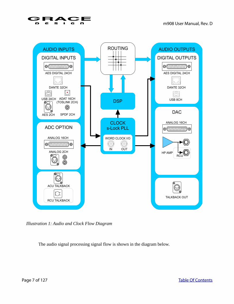
The Audio and Clock flow is shown in the simplified block diagram below.
Page 6 of 127 Table Of Contents
m908 User Manual, Rev. D
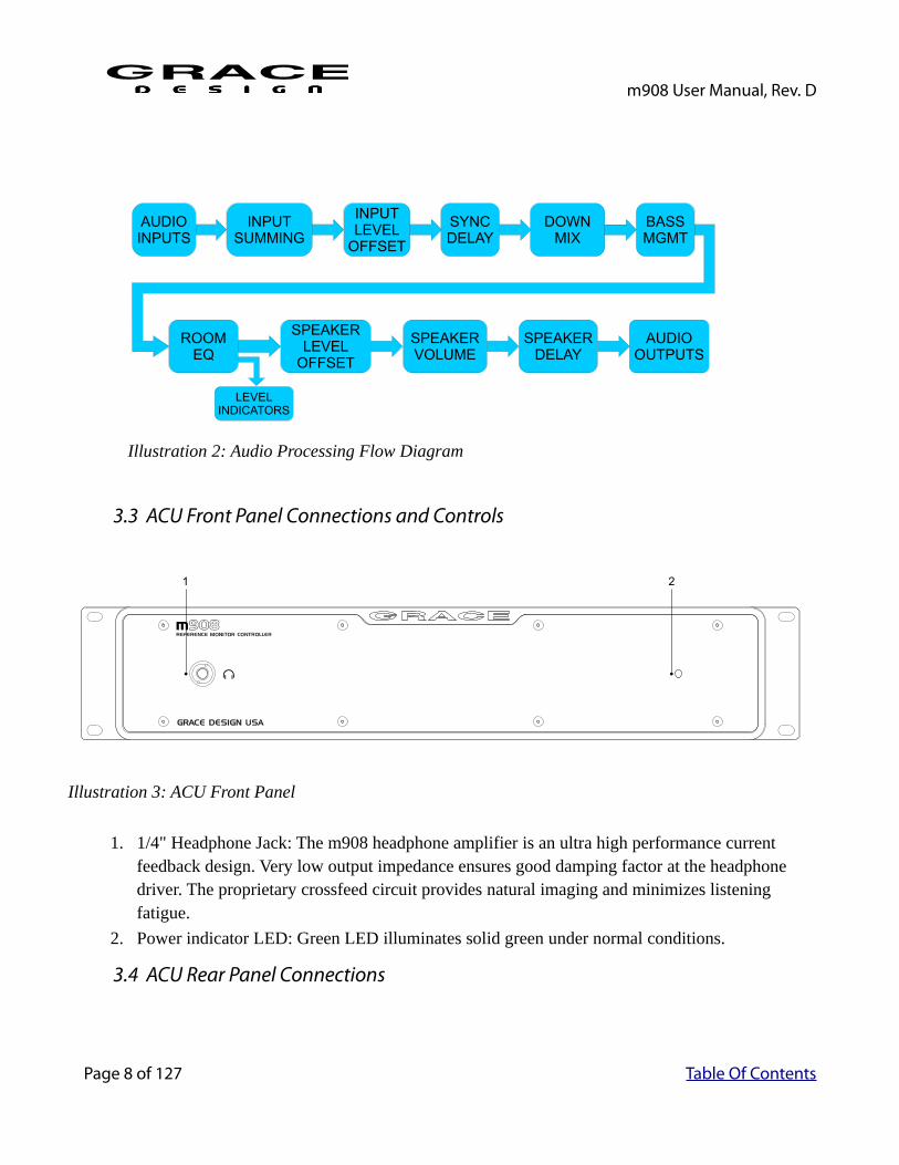
The audio signal processing signal flow is shown in the diagram below.
Page 7 of 127 Table Of Contents
AUDIO INPUTS ROUTING
DSP
ADC OPTION
ANALOG 16CH
ANALOG 2CH
AUDIO OUTPUTS
DAC
ANALOG 16CH
HP AMPRCU
DIGITAL OUTPUTS
AES DIGITAL 24CH
USB 8CH
DANTE 32CH
CLOCKs-Lock PLL
WORD CLOCK I/O
IN OUT
ACU TALKBACK
RCU TALKBACK
DIGITAL INPUTS
AES DIGITAL 24CH
USB 24CH ADAT 16CH(TOSLINK 2CH)
DANTE 32CH
SPDF 2CHAES 2CH
TALKBACK OUT
Illustration 1: Audio and Clock Flow Diagram
m908 User Manual, Rev. D
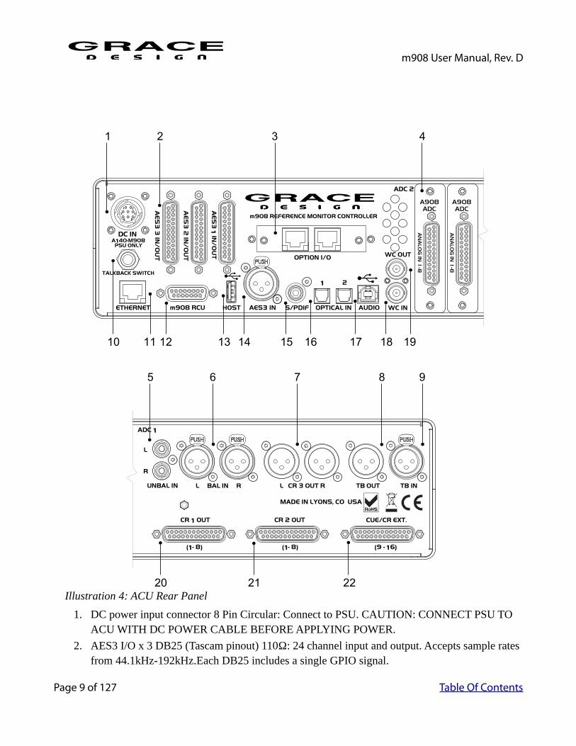
3.3 ACU Front Panel Connections and Controls
1. 1/4" Headphone Jack: The m908 headphone amplifier is an ultra high performance current feedback design. Very low output impedance ensures good damping factor at the headphone driver. The proprietary crossfeed circuit provides natural imaging and minimizes listening fatigue.
2. Power indicator LED: Green LED illuminates solid green under normal conditions.
3.4 ACU Rear Panel Connections
Page 8 of 127 Table Of Contents
1 2
Illustration 3: ACU Front Panel
AUDIOINPUTS
SYNCDELAY
INPUTLEVEL
OFFSET
BASSMGMT
SPEAKERDELAY
INPUTSUMMING
AUDIOOUTPUTS
SPEAKERVOLUME
SPEAKERLEVEL
OFFSET
ROOMEQ
DOWNMIX
LEVELINDICATORS
Illustration 2: Audio Processing Flow Diagram
m908 User Manual, Rev. D
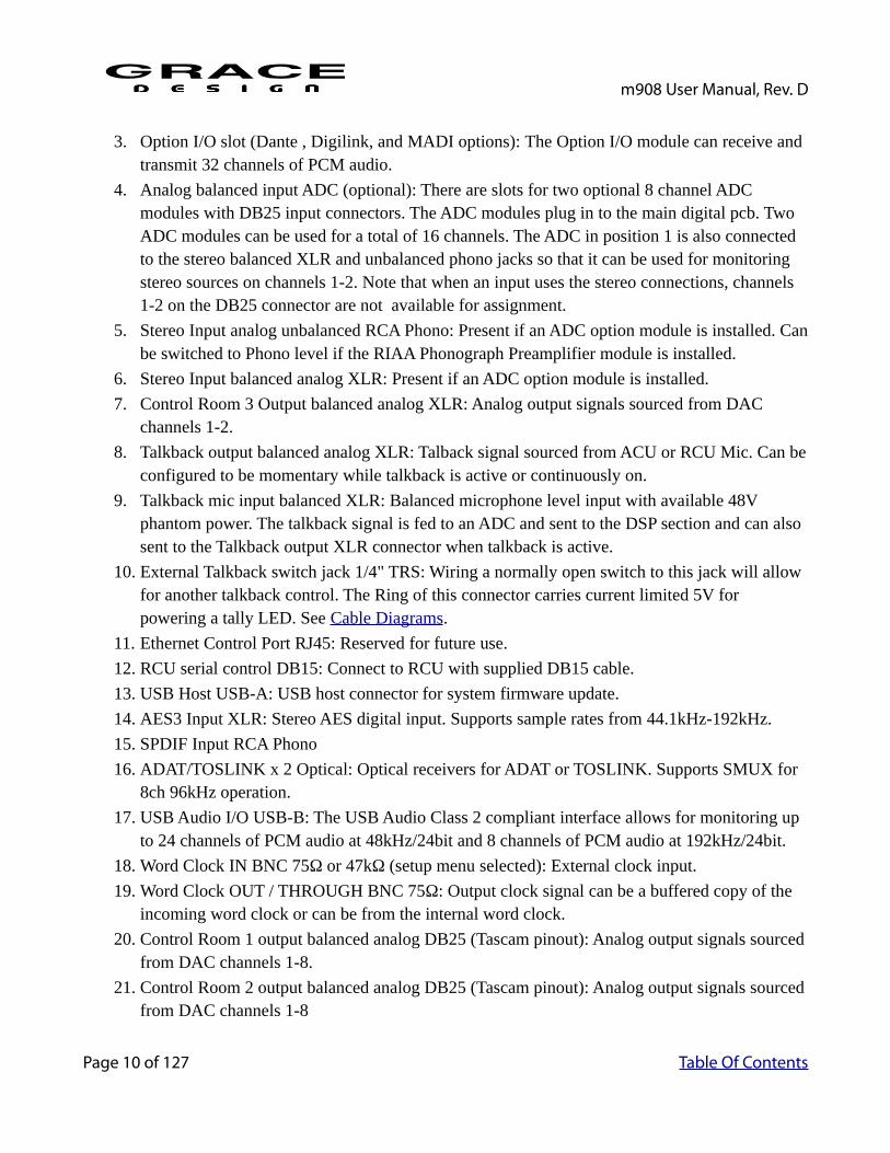
1. DC power input connector 8 Pin Circular: Connect to PSU. CAUTION: CONNECT PSU TO ACU WITH DC POWER CABLE BEFORE APPLYING POWER.
2. AES3 I/O x 3 DB25 (Tascam pinout) 110Ω: 24 channel input and output. Accepts sample rates from 44.1kHz-192kHz.Each DB25 includes a single GPIO signal.
Page 9 of 127 Table Of Contents
5 6 7 8 9
20 21 22
1 2
10 11
3 4
12 13 14 15 16 17 18 19
TB INTB OUT
(1- 8)
BAL INUNBAL IN
R
L
L L
ADC 1
R CR 3 OUT R
MADE IN LYONS, CO USA
CUE/CR EXT.CR 1 OUT CR 2 OUT
(1- 8) (9 - 16)
14
1
14
1
14
1
m908 RCU
AE
S3
1 IN/O
UT
DC INA140-M908
ETHERNET AES3 IN S/PDIF OPTICAL IN AUDIO WC IN
WC OUTOPTION I/O
AE
S3
3 IN
/OU
T
AE
S3
2 IN
/OU
T
HOST
TALKBACK SWITCH
ADC 2
m908 REFERENCE MONITOR CONTROLLER
PSU ONLY
1 2
A908
AN
ALO
G IN
1-8
ADCA908
AN
ALO
G IN
1-8
ADC
14
1 14
1 14
1
9
1
14
1 14
1
86
5
21
3
Illustration 4: ACU Rear Panel
m908 User Manual, Rev. D
3. Option I/O slot (Dante , Digilink, and MADI options): The Option I/O module can receive and transmit 32 channels of PCM audio.
4. Analog balanced input ADC (optional): There are slots for two optional 8 channel ADC modules with DB25 input connectors. The ADC modules plug in to the main digital pcb. Two ADC modules can be used for a total of 16 channels. The ADC in position 1 is also connected to the stereo balanced XLR and unbalanced phono jacks so that it can be used for monitoring stereo sources on channels 1-2. Note that when an input uses the stereo connections, channels 1-2 on the DB25 connector are not available for assignment.
5. Stereo Input analog unbalanced RCA Phono: Present if an ADC option module is installed. Canbe switched to Phono level if the RIAA Phonograph Preamplifier module is installed.
6. Stereo Input balanced analog XLR: Present if an ADC option module is installed.
7. Control Room 3 Output balanced analog XLR: Analog output signals sourced from DAC channels 1-2.
8. Talkback output balanced analog XLR: Talback signal sourced from ACU or RCU Mic. Can beconfigured to be momentary while talkback is active or continuously on.
9. Talkback mic input balanced XLR: Balanced microphone level input with available 48V phantom power. The talkback signal is fed to an ADC and sent to the DSP section and can also sent to the Talkback output XLR connector when talkback is active.
10. External Talkback switch jack 1/4" TRS: Wiring a normally open switch to this jack will allow for another talkback control. The Ring of this connector carries current limited 5V for powering a tally LED. See Cable Diagrams.
11. Ethernet Control Port RJ45: Reserved for future use.
12. RCU serial control DB15: Connect to RCU with supplied DB15 cable.
13. USB Host USB-A: USB host connector for system firmware update.
14. AES3 Input XLR: Stereo AES digital input. Supports sample rates from 44.1kHz-192kHz.
15. SPDIF Input RCA Phono
16. ADAT/TOSLINK x 2 Optical: Optical receivers for ADAT or TOSLINK. Supports SMUX for 8ch 96kHz operation.
17. USB Audio I/O USB-B: The USB Audio Class 2 compliant interface allows for monitoring up to 24 channels of PCM audio at 48kHz/24bit and 8 channels of PCM audio at 192kHz/24bit.
18. Word Clock IN BNC 75Ω or 47kΩ (setup menu selected): External clock input.
19. Word Clock OUT / THROUGH BNC 75Ω: Output clock signal can be a buffered copy of the incoming word clock or can be from the internal word clock.
20. Control Room 1 output balanced analog DB25 (Tascam pinout): Analog output signals sourcedfrom DAC channels 1-8.
21. Control Room 2 output balanced analog DB25 (Tascam pinout): Analog output signals sourcedfrom DAC channels 1-8
Page 10 of 127 Table Of Contents
m908 User Manual, Rev. D
22. CUE/WIDE OUT balanced analog DB25 (Tascam pinout): Analog output signals sourced fromDAC channels 9-16. These outputs can be for speakers in immersive playback systems or for CUE outputs. CUE outputs have level control, assignable talkback summing, and MON>CUE routing. MON>CUE sends the Left and Right signal from the current monitor signal to the CUE output. In the case of multi-channel monitoring the Left and Right signal or a stereo downmix can be sent to the CUE output.
3.5 RCU DescriptionThe Remote Control Unit is designed to be a seamless interface between the user and the
audio system being controlled. We have carefully selected the display, switches, and encoder to be long life and provide excellent tactile feedback. All of the necessary information is displayed on the 1/4WVGA display while the most used functions have dedicated switches. There is a 1/4" headphone jack on the rear of the RCU for convenient access to the m908s high performance headphone amplifier.
The RCU sits on a tilting base so it can be adjusted to the most comfortable angle. The built intalkback microphone on the RCU also doubles as an accurate sound pressure level (SPL) meter.
The RCU is powered from the ACU via the DB15 cable.
3.6 RCU Front Panel ControlsMany of the most used monitoring functions are directly accessed through the push button
switches on the RCU front panel. Primary functions are accessed with a press-release. Where a switch has more than one function the primary function is indicated with large upper case letters. The secondary function is indicated in small letters and is accessed with a push-hold of the switch. Some switches can have secondary functions assigned to them by the user. These switches do not have lower case labeling.
Page 11 of 127 Table Of Contents
m908 User Manual, Rev. D
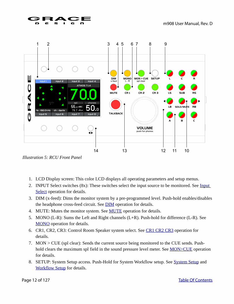
1. LCD Display screen: This color LCD displays all operating parameters and setup menus.
2. INPUT Select switches (8x): These switches select the input source to be monitored. See Input Select operation for details.
3. DIM (x-feed): Dims the monitor system by a pre-programmed level. Push-hold enables/disablesthe headphone cross-feed circuit. See DIM operation for details.
4. MUTE: Mutes the monitor system. See MUTE operation for details.
5. MONO (L-R): Sums the Left and Right channels (L+R). Push-hold for difference (L-R). See MONO operation for details.
6. CR1, CR2, CR3: Control Room Speaker system select. See CR1 CR2 CR3 operation for details.
7. MON > CUE (spl clear): Sends the current source being monitored to the CUE sends. Push-hold clears the maximum spl field in the sound pressure level meter. See MON>CUE operation for details.
8. SETUP: System Setup access. Push-Hold for System Workflow setup. See System Setup and Workflow Setup for details.
Page 12 of 127 Table Of Contents
TALKBACK
VOLUMEpush for phones
MUTE
SETUPMON > CUE
CR 2 CR 3
MONOx-feedDIM
spl clearL - RL C R
RSLS SUB
RBSOLO/MUTE
A
LB
B C
CR 1
21 3 4 7 8 9
10111213
5 6
14
Illustration 5: RCU Front Panel
m908 User Manual, Rev. D
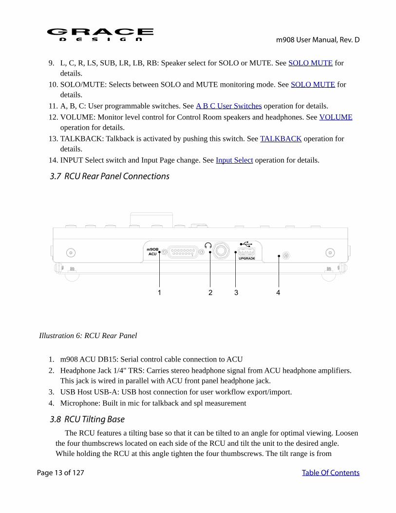
9. L, C, R, LS, SUB, LR, LB, RB: Speaker select for SOLO or MUTE. See SOLO MUTE for details.
10. SOLO/MUTE: Selects between SOLO and MUTE monitoring mode. See SOLO MUTE for details.
11. A, B, C: User programmable switches. See A B C User Switches operation for details.
12. VOLUME: Monitor level control for Control Room speakers and headphones. See VOLUME operation for details.
13. TALKBACK: Talkback is activated by pushing this switch. See TALKBACK operation for details.
14. INPUT Select switch and Input Page change. See Input Select operation for details.
3.7 RCU Rear Panel Connections
1. m908 ACU DB15: Serial control cable connection to ACU
2. Headphone Jack 1/4" TRS: Carries stereo headphone signal from ACU headphone amplifiers. This jack is wired in parallel with ACU front panel headphone jack.
3. USB Host USB-A: USB host connection for user workflow export/import.
4. Microphone: Built in mic for talkback and spl measurement
3.8 RCU Tilting BaseThe RCU features a tilting base so that it can be tilted to an angle for optimal viewing. Loosen
the four thumbscrews located on each side of the RCU and tilt the unit to the desired angle. While holding the RCU at this angle tighten the four thumbscrews. The tilt range is from
Page 13 of 127 Table Of Contents
m908ACU
1 2 3 4
Illustration 6: RCU Rear Panel
m908 User Manual, Rev. D
horizontal to 30º.
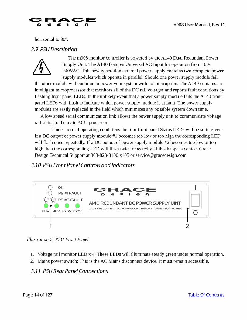
3.9 PSU DescriptionThe m908 monitor controller is powered by the A140 Dual Redundant Power
Supply Unit. The A140 features Universal AC Input for operation from 100-240VAC. This new generation external power supply contains two complete powersupply modules which operate in parallel. Should one power supply module fail
the other module will continue to power your system with no interruption. The A140 contains an intelligent microprocessor that monitors all of the DC rail voltages and reports fault conditions byflashing front panel LEDs. In the unlikely event that a power supply module fails the A140 front panel LEDs with flash to indicate which power supply module is at fault. The power supply modules are easily replaced in the field which minimizes any possible system down time.
A low speed serial communication link allows the power supply unit to communicate voltage rail status to the main ACU processor.
Under normal operating conditions the four front panel Status LEDs will be solid green. If a DC output of power supply module #1 becomes too low or too high the corresponding LED will flash once repeatedly. If a DC output of power supply module #2 becomes too low or too high then the corresponding LED will flash twice repeatedly. If this happens contact Grace Design Technical Support at 303-823-8100 x105 or [email protected]
3.10 PSU Front Panel Controls and Indicators
1. Voltage rail monitor LED x 4: These LEDs will illuminate steady green under normal operation.
2. Mains power switch: This is the AC Mains disconnect device. It must remain accessible.
3.11 PSU Rear Panel Connections
Page 14 of 127 Table Of Contents
A140 REDUNDANT DC POWER SUPPLY UINT
OK
PS #1 FAULT
PS #2 FAULT
CAUTION: CONNECT DC POWER CORD BEFORE TURNING ON POWER+18V +6.5V +50V-18V
1 2
Illustration 7: PSU Front Panel
m908 User Manual, Rev. D
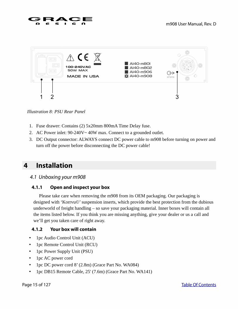
1. Fuse drawer: Contains (2) 5x20mm 800mA Time Delay fuse.
2. AC Power inlet: 90-240V~ 40W max. Connect to a grounded outlet.
3. DC Output connector: ALWAYS connect DC power cable to m908 before turning on power andturn off the power before disconnecting the DC power cable!
4 Installation 4.1 Unboxing your m908
4.1.1 Open and inspect your box
Please take care when removing the m908 from its OEM packaging. Our packaging is designed with ‘Korrvu©’ suspension inserts, which provide the best protection from the dubious underworld of freight handling – so save your packaging material. Inner boxes will contain all the items listed below. If you think you are missing anything, give your dealer or us a call and we’ll get you taken care of right away.
4.1.2 Your box will contain
• 1pc Audio Control Unit (ACU)
• 1pc Remote Control Unit (RCU)
• 1pc Power Supply Unit (PSU)
• 1pc AC power cord
• 1pc DC power cord 8’ (2.8m) (Grace Part No. WA084)
• 1pc DB15 Remote Cable, 25' (7.6m) (Grace Part No. WA141)
Page 15 of 127 Table Of Contents
A140-m801A140-m802A140-m906A140-m908MADE IN USA
100-240VAC50W MAX
2 31
Illustration 8: PSU Rear Panel
m908 User Manual, Rev. D
• 1pc USB 2.0 Cable, Type A to Type B, 6 foot (Grace Part No. WA551)
• 2pc spare fuses. 800mA 250V~ Time Delay 5x20mm (Grace Part No. F101, Littlefuse 0239.800HXP or equivalent)
• 4pc Adhesive backed rubber feet, 0.12" thick (Grace Part No. H560)
• 4pc Adhesive backed rubber feet, 0.23" thick (Grace Part No. H580)
• 4pc 10-32 X 3/4 Truss Head Phillips rack mount screw (Grace Part No. H455)
• 1pc USB flash drive with m908 User Manual
4.1.3 REGISTER YOUR UNIT
We strongly urge you to fill out your warranty registration card. The m908 is covered by a 5 year transferable warranty. Registering your unit will help us contact you if there are important updates and simplifies warranty service. So please take a few minutes to complete and send in the enclosed card, or simply fill out the warranty registration form on our website. We always keep your information private. Thank you!
4.2 Connecting the m908
4.2.1 Power Connections
A DC power cord is supplied to connect the PSU to the ACU. This cord can be identified by the 8 pin circular connectors at each end.
Please note that the DC power cord should be connected before the AC power is turned on. This prevents incorrect power sequencing which can cause damage to the audio circuits. To avoid any interference with the low level audio circuitry, the power supply should be located at least 3’ (1m) from the ACU.
WARNING: A damaged DC power cord can create a shock hazard as voltages of 72VDC can be present.
Do not operate the m908 with a damaged DC power cord. If damage occurs, please contact Grace Design for a replacement. A standard AC power cable is included. For safety, the power supply cord must be connected to a grounded outlet.
4.2.2 Audio Connections
Talkback Microphone Input: Female XLR, pin 2 positive, pin 3 negative and pin 1 ground. 48V phantom power is supplied on pins 2 and 3. With a gain range +11dB and +19-74dB in 1dB steps this input can be used for any type of microphone.
Talkback Microphone Output: Male XLR, balanced, pin 2 positive, pin 3 negative and pin 1ground. Provides a direct output of the talkback signal when talkback is active. See the Talkback setup section of this manual for details.
Page 16 of 127 Table Of Contents
m908 User Manual, Rev. D
Analog Balanced Control Room Outputs: DB25 Tascam pinout (See CABLE DIAGRAMS). These outputs are defined in the setup menus for your Control Room speaker system.
Analog Balanced CUE/WIDE Outputs: DB25 Tascam pinout (See CABLE DIAGRAMS). Depending on your workflow these outputs are defined in the setup menus for your additional surround/overhead speakers or CUE outputs.
Analog Balanced Stereo Control Room Output: Male XLR, balanced, pin 2 positive, pin 3 negative and pin 1 ground. These outputs are defined in the setup menus for your Control Room speaker system.
AES3 Digital I/O: DB25 Tascam pinout, 110Ω (See CABLE DIAGRAMS)
ADAT Lightpipe / TOSLINK Inputs: In ADAT Lightpipe Mode these optical jacks provide 8 channels of audio data on each (at 44.1kHz and 48kHz). With ADAT S-MUX enabled 88.2kHz or 96kHz sample rate audio channels 1-4 are received on OPTICAL input 1, while channels 5-8 are received on OPTICAL input 2. 176.4kHz and 192kHz sample rates are not supported over theADAT interface. In TOSLINK mode stereo signals up to 96kHz can be received on each connector. See the System Setup section of this manual for details on configuring the optical input connectors.
SPDIF Digital Stereo Input: RCA Phono jack, 75Ω. This input will receive PCM audio signal sample rates from 44.1kHz to 192kHz.
USB Class 2 Audio Interface: USB Type B jack. This interface is capable of 24 channel input from host computer and 8 channel output to the host computer. Use a standard USB type A -to- type B cable (included with your m908). The type A connector is to be plugged in to the HOST computer and the type B connector to the m908 input. PCM 44.1kHz – 192kHz/24 bit is supported. Please refer to USB Audio Setup.
4.2.3 Optional ADC Module Connections
Analog Balanced 8 Channel Line Inputs: DB25 Tascam Pinout (see CABLE DIAGRAMS).8 channel ADC module balanced inputs. See ADC option details in the ADC Option Module section of this manual.
Analog Balanced Stereo Line Input: Female XLR, balanced, pin 2 positive, pin 3 negative and pin 1 ground. Supplied with ADC Option Module. Allows for the connection of balanced stereo sources to the ADC. Left channel is connected to ADC 1 channel 1 and Right channel is connected to ADC 1 channel 2.
Analog Unbalanced Stereo Line Input: RCA Phono. Supplied with ADC Option Module. Allows for the connection of unbalanced stereo sources to the ADC. Left channel is connected to ADC 1 channel 1 and Right channel is connected to ADC 1 channel 2.
Page 17 of 127 Table Of Contents
m908 User Manual, Rev. D
4.2.4 Clock and Control Connections
REMOTE CONNECTOR: DB15 The m908 RCU handles all system control. Connection to the m908 RCU is via this DB15 connector, which carries RS485 serial data, DC power and headphone signals. The m908 ships with a high quality 25’ cable. Custom cables can be assembled by the user according to the diagrams in the Cable Diagram section of this manual. While the serial data can travel over 1000 feet we do not recommend cables longer than 50’ for headphone use. If you need a longer, cable contact your Grace Design dealer or us directly. Do NOT use an off the shelf DB15 cable as the pinout will be incompatible and may cause damage to your system.
WORD CLOCK IN: BNC 75Ω or 47kΩ (setup menu selected). The m908 can accept a standard 5V/75Ω word clock signal from an external clock generating unit. This might be a stand-alone clock source or via, for example, the word clock output from your digital audio workstation. The m908 locks to the incoming word clock with an ultra low jitter PLL. The PLL has a fast lock mode which rapidly acquires lock and then switches to a high jitter rejection modewith a loop bandwidth of 0.5Hz. This provides exceptional jitter rejection for the DAC and ADC sample clocks. In the event of a dropout or loss of incoming word clock signal, the intelligent PLL will remain at the last known valid frequency. When the signal is restored the PLL will smoothly re-acquire lock.
WORD CLOCK OUT: BNC 75Ω. The word clock output allows the user to synchronize other digital audio equipment to the m908. When the system menu setting "clock output" is set toexternal, this connector output is a buffered copy of the signal on the word clock IN jack. This mode is useful for "daisy chaining" to other units in a system. When "clock output" is set to system clock this connector outputs a buffered copy of the internal m908 word clock. The output is buffered and is designed to drive a 75Ω line.
ETHERNET: RJ45. This is a standard 1000 Base-T Ethernet interface. Currently it is reserved for factory diagnostics.
USB HOST: USB A connector. This host connector is intended for firmware upgrades.
EXT. TALKBACK: 1/4" TRS Jack. External talkback control. This input allows the connection of an external switch, such as a footswitch, for remotely activating the ACU talkback mic input, or the built in talkback mic on the RCU. The input is a TRS jack and is used with a “normally open” switching device. Note that when using this jack the associated talkback function can be assigned in talkback setup. See the remote talkback cable diagram at the end of this manual for connection details.
4.2.5 Thermal Management
The m908 ACU requires adequate ventilation to maintain proper operating temperature.
Under normal operating conditions the m908 will dissipate 30-35W of power depending on user settings and hardware options. To protect the m908 from excessively high internal
Page 18 of 127 Table Of Contents
m908 User Manual, Rev. D
temperatures, and to ensure long term reliability, it is equipped with a 40mm variable speed fan. Whether or not this fan turns on is dependent on several variables. These are: ambient temperature, whether there is air movement around the m908, and if the m908 is mounted directly above or below other heat generating equipment.
The variable speed fan comes on to cool the internal circuits if the main circuit board temperature rises above 55ºC (131ºF). The fan has three speed ranges which are triggered by the following pcb temperature thresholds:
1. Low: 55ºC (131ºF)
2. Med: 60ºC (140ºF)
3. High: 65ºC (149ºF)
If the m908 is mounted without space above and below and it is adjacent to heat generating devices then the internal temperature can rise above 55ºC and the fan will come on.
If the m908 is being used in an area where fan noise is undesirable it is recommended that the m908 be mounted such that it has space below and above the chassis and where the ambient temperature does not exceed 30ºC (86ºF).
5 OperationOut of the box the m908 comes with a many factory presets that will allow for quickly
connecting the most common input sources, cue, and speaker systems. If your installation requires customization, then see the Workflow Setup and Setup sections of this manual. Otherwise read this section for the basics on operating the m908.
The m908 uses a closed loop control system to ensure that the status reported on the RCU matches the actual hardware setting in the ACU. Any changes made to the configuration of the system are transmitted to the ACU, where they are processed and reported back to the RCU for confirmation. The following sections detail all of the controls and features of the normal operation mode.
5.1 Manual conventionsThroughout the Operation and Setup sections of this manual references to screen elements and
setup menu parameters will use the following formatting:
• Hardware controls and connectors will be in ALL CAPITAL LETTERS
• Switches with secondary functions will be (in parentheses)
• Setup menu screen names will have the First Letter capitalized
• Setup parameter names will be in bold lower case
• Setup parameter values will be <enclosed>
Page 19 of 127 Table Of Contents
m908 User Manual, Rev. D
• "push" refers to a quick push and release of a switch.
• "push-hold" refers to a 1/2 second push and hold of a switch.
• "push long-hold" refers to a 3 second push and hold of a switch.
5.2 Power UpAfter making the appropriate power and signal connections turn on the m908 PSU.
NOTE: It is always recommended that power amplifiers and powered monitor speaker be turned on after the m908 to avoid any transients reaching the loudspeakers.
The illuminated switches on the RCU will go through a test sequence and then the LCD display will indicate that the system firmware is loading. This process takes approximately 1 minute.
Once the system has loaded the RCU will display the Home Screen and the m908 will be operational.
5.3 Home Screen
Page 20 of 127 Table Of Contents
Illustration 9: m908 System Load Splash Screen
m908 User Manual, Rev. D
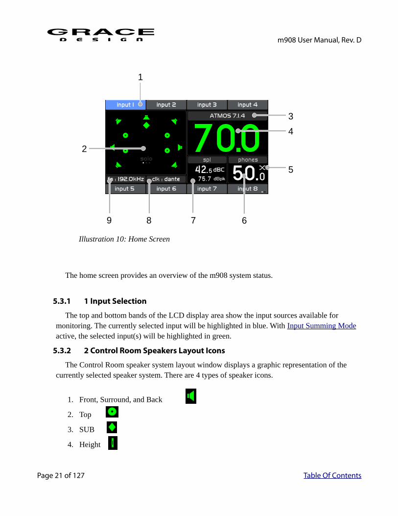
The home screen provides an overview of the m908 system status.
5.3.1 1 Input Selection
The top and bottom bands of the LCD display area show the input sources available for monitoring. The currently selected input will be highlighted in blue. With Input Summing Mode active, the selected input(s) will be highlighted in green.
5.3.2 2 Control Room Speakers Layout Icons
The Control Room speaker system layout window displays a graphic representation of the currently selected speaker system. There are 4 types of speaker icons.
1. Front, Surround, and Back
2. Top
3. SUB
4. Height
Page 21 of 127 Table Of Contents
Illustration 10: Home Screen
1
2
3
4
5
8 7 69
m908 User Manual, Rev. D
Each icon also acts as a signal level indicator. The level is monitored after bass management, room EQ, and downmix processing and before speaker volume control and output delay..
• White No signal present.
• Green Signal greater than -50dBFS
• Yellow Signal greater than -6dBFS
• Red Signal OVER
In the lower center area of the speaker system layout window is the solo/mute page and status.The word "solo" will be visible in gray when the system is in solo mode. The word solo will be visible in white when there is a speaker in solo mode.
The word "mute" will be visible in gray when the system is in mute mode. The word "mute" will be visible in white when there is one or more speaker in mute mode.
The speaker system can be configured in the Speaker Output setup
5.3.3 3 Control Room Speaker Output
The name of the currently selected Control Room speaker system is displayed directly above the Control Room Monitor Level.
5.3.4 4 Control Room Monitor Level
The current Control Room monitor level is displayed in large numbers which will be green when the encoder is controlling the Control Room level. The default volume range is 0-100 in 0.5dB steps. 0 is mute and 96 is unity gain.
The Control Room Monitor Level can also be displayed with a user defined reference level. This way the volume readout can be calibrated to SPL.
See Monitor Control setup for details on configuring the Control Room Monitor Level display.
5.3.5 5 Headphone Crossfeed
The Headphone Crossfeed circuit status is displayed in the upper right corner of the headphones volume display window. See the X-FEED section of this manual for details.
5.3.6 6 Headphone Monitor Level
The current headphone monitor level is displayed in small numbers which will be green when the encoder is controlling the headphone level. If headphones are disabled in the system workflow then the Headphone Monitor Level display will read: HEADPHONES DISABLED. However, the headphone amplifier can still be used for low latency cue monitoring. See the CUE setup section of this manual for details.
When enabled, the headphone amplifier signal source can be set to monitor the Left and Right channels of the current Control Room output, any of the CUE paths that are enabled, or the HP/CUE Downmixer.
Page 22 of 127 Table Of Contents
m908 User Manual, Rev. D
See Monitor Control setup for details on configuring the Headphone Monitoring.
5.3.7 7 SPL Meter
Using the internal m908 RCU microphone, the m908 computes the real-time sound pressure level based on the system configuration. The current and peak SPL levels are displayed along with the filter mode in this section of the display. The peak spl value can be cleared at any time with a push-hold of the MON>CUE (spl-clear) switch. The SPL measurement settings are configured in SPL Meter setup.
When talkback is activated on the RCU, SPL monitoring will be suspended and the built in microphone will switch to become the talback mic. The SPL Display area will indicate TALKBACK ACTIVE. Upon exiting Talkback the SPL meter will return to normal operation.
5.3.8 8 Clock Source and Status
The clock status window displays the current clock source and indicates it's status by changingthe color of the text. See the Clocking section of this manual for details.
5.3.9 9 System Sample Rate
The sample rate display indicates the sample rate detected on the input connector. If the input data or sample rate are invalid then the sample rate display will be blank (--).
5.4 INPUT SELECTThe m908 features a total of 16 input sources which are accessed with 8 dedicated INPUT
Select switches, in 2 rows of 4, above and below the LCD display. Each INPUT Select switch is located adjacent to it's name area in the upper and lower bands of the display area. Pushing any of these switches will select the associated input source and connect it to the monitoring path. When an input is selected for monitoring it's name area background will be blue. Inactive inputs will have a gray background in the name area.
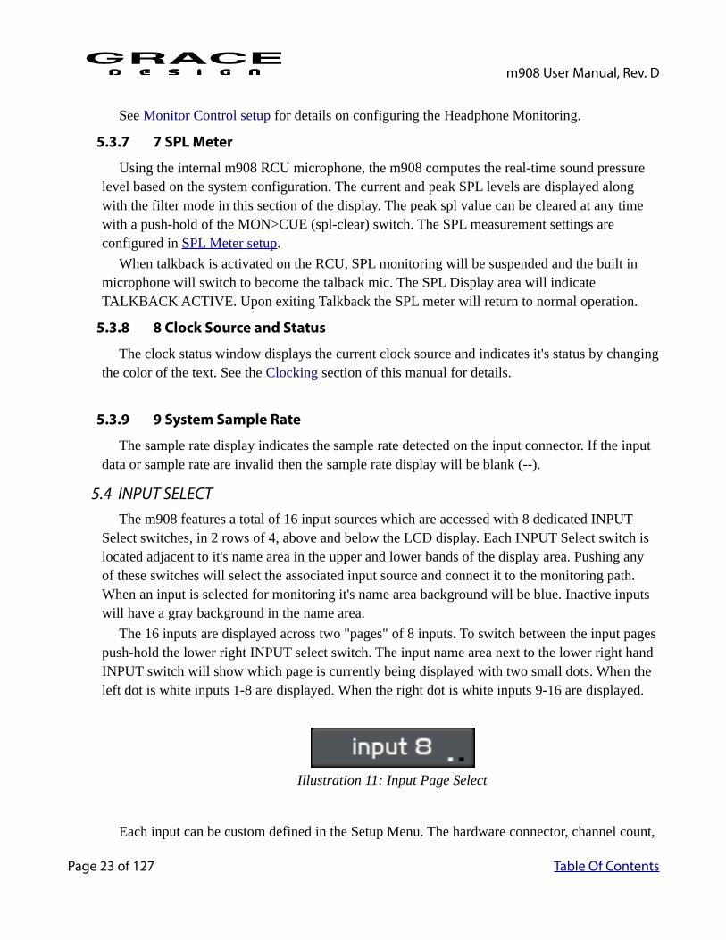
The 16 inputs are displayed across two "pages" of 8 inputs. To switch between the input pagespush-hold the lower right INPUT select switch. The input name area next to the lower right hand INPUT switch will show which page is currently being displayed with two small dots. When the left dot is white inputs 1-8 are displayed. When the right dot is white inputs 9-16 are displayed.
Each input can be custom defined in the Setup Menu. The hardware connector, channel count,
Page 23 of 127 Table Of Contents
Illustration 11: Input Page Select
m908 User Manual, Rev. D
level offset, sync delay, clock override mode, and name can be configured. See the Input Setup section of this manual for details.
5.4.1 Input Summing Mode
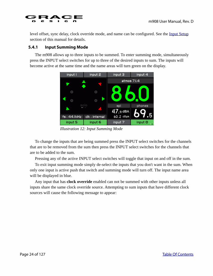
The m908 allows up to three inputs to be summed. To enter summing mode, simultaneously press the INPUT select switches for up to three of the desired inputs to sum. The inputs will become active at the same time and the name areas will turn green on the display.
To change the inputs that are being summed press the INPUT select switches for the channels that are to be removed from the sum then press the INPUT select switches for the channels that are to be added to the sum.
Pressing any of the active INPUT select switches will toggle that input on and off in the sum.
To exit input summing mode simply de-select the inputs that you don't want in the sum. When only one input is active push that switch and summing mode will turn off. The input name area will be displayed in blue.
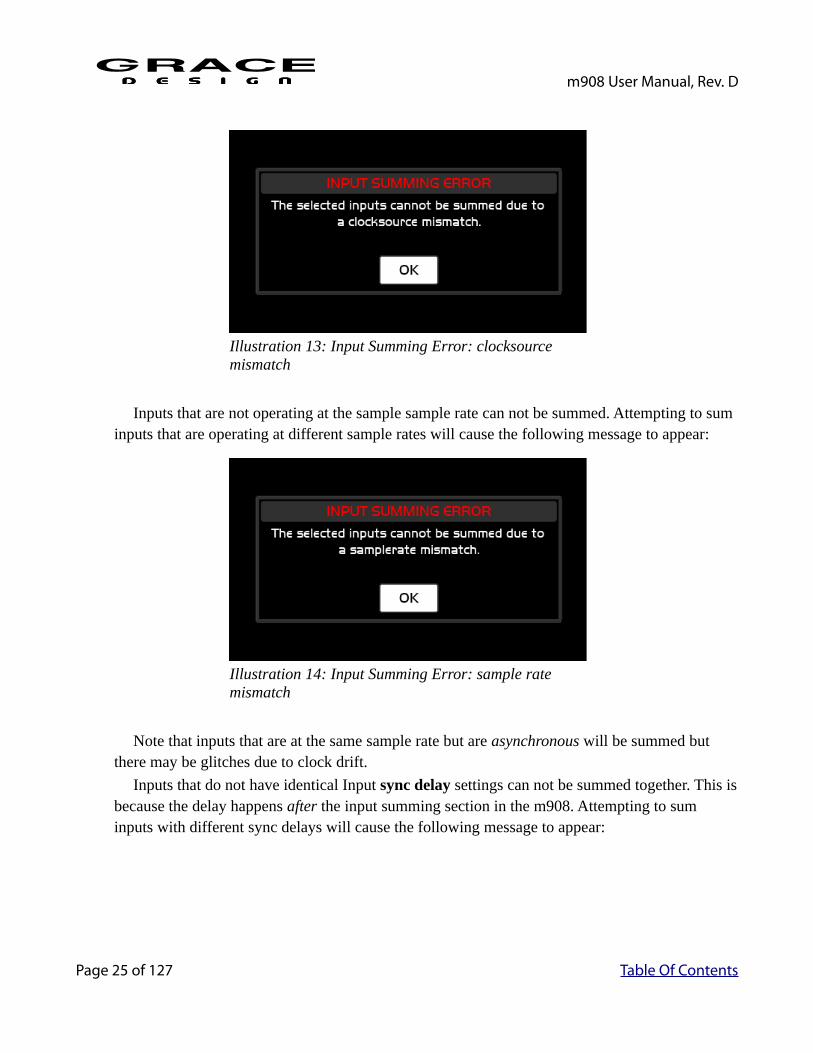
Any input that has clock override enabled can not be summed with other inputs unless all inputs share the same clock override source. Attempting to sum inputs that have different clock sources will cause the following message to appear:
Page 24 of 127 Table Of Contents
Illustration 12: Input Summing Mode
m908 User Manual, Rev. D
Inputs that are not operating at the sample sample rate can not be summed. Attempting to sum inputs that are operating at different sample rates will cause the following message to appear:
Note that inputs that are at the same sample rate but are asynchronous will be summed but there may be glitches due to clock drift.
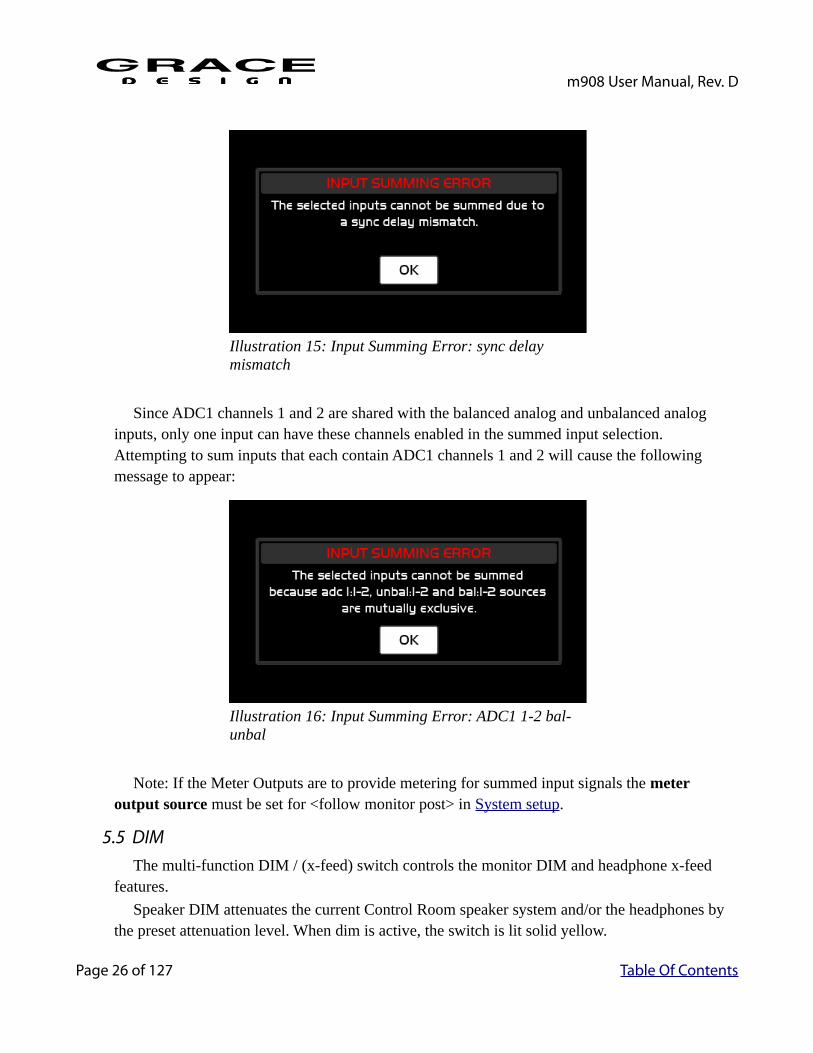
Inputs that do not have identical Input sync delay settings can not be summed together. This isbecause the delay happens after the input summing section in the m908. Attempting to sum inputs with different sync delays will cause the following message to appear:
Page 25 of 127 Table Of Contents
Illustration 13: Input Summing Error: clocksource mismatch
Illustration 14: Input Summing Error: sample rate mismatch
m908 User Manual, Rev. D
Since ADC1 channels 1 and 2 are shared with the balanced analog and unbalanced analog inputs, only one input can have these channels enabled in the summed input selection. Attempting to sum inputs that each contain ADC1 channels 1 and 2 will cause the following message to appear:
Note: If the Meter Outputs are to provide metering for summed input signals the meter output source must be set for <follow monitor post> in System setup.
5.5 DIMThe multi-function DIM / (x-feed) switch controls the monitor DIM and headphone x-feed
features.
Speaker DIM attenuates the current Control Room speaker system and/or the headphones by the preset attenuation level. When dim is active, the switch is lit solid yellow.
Page 26 of 127 Table Of Contents
Illustration 15: Input Summing Error: sync delay mismatch
Illustration 16: Input Summing Error: ADC1 1-2 bal-unbal
m908 User Manual, Rev. D
DIM level and which outputs it affects can be configured in Dim setup.
5.6 X-FEEDPress-hold of the DIM / (x-feed) switch engages the Headphone cross-feed circuit in the
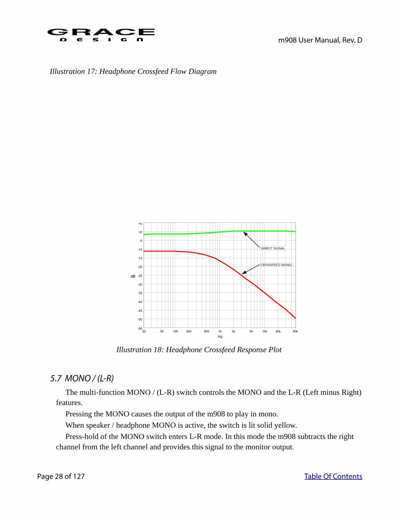
headphone output. When x-feed is active it is indicated on the headphone status display. X-feed (cross-feed) simulates the acoustics of a loudspeaker listening environment which can significantly improve imaging while reducing listening fatigue when using headphones. This feature employs carefully designed signal cross-feed, filtering and delay circuits to simulate hrtf (head related transfer functions).
Press-hold the DIM (x-feed) switch to toggle Headphone Crossfeed on and off. Crossfeed is indicated in the upper right corner the phones volume window.
When listening to loudspeakers in a room, your left ear hears sound primarily from the left speaker (and vice versa) but also receives a signal from the right speaker at a lower level and with some time delay compared to the right ear. As well, the right speaker sound that reaches the left ear does not have a flat frequency response as the sound waves have traveled around the shape of your head before reaching your left ear. The brain uses delay, level and frequency response characteristics to process the location of a sound and hence, create an aural image.
When listening to a stereo (or down-mixed) signal through headphones, each ear only hears the sound from one transducer and the mixing of signals between the ears does not exist. In this situation the brain is left without many of the psycho acoustic clues required to generate a properly distributed image and an accurate sound stage. The result is that sounds seem to cluster in the far left, far right or center of your head. Since the vital clues are absent, the brain has a difficult time deciding how to process the sounds coming from the headphone, which can result in listening fatigue when listening for extended periods of time. The m908 contains circuitry which electronically simulates the signal cross-feed that occurs in a real acoustic space and helps the brain establish instrument locations across the entire sound stage. While it is difficult to perfectly model the very complex level, delay and frequency response characteristics of the head,the cross-feed circuitry in the m908 gives the brain some of the basic clues it needs and the resultis a very pleasing simulation of an acoustic space. We chose the parameters of the cross-feed circuit to find a good compromise between accurate imaging and tonal neutrality. For recreationallistening there could be more aggressive modeling of the head related transfer function (HRTF) but this is usually at the expense of adding tone color. For critical monitoring during the recording/editing/mixing process the user will find that the m908 cross-feed circuit provides a sonically neutral character.
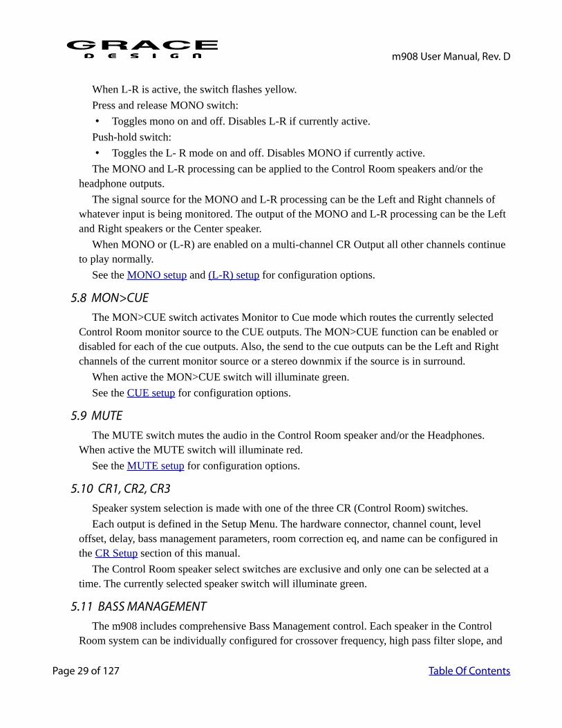
Below is a flow diagram and frequency response plot showing the response of the m908 crossfeed circuit. In this graph one channel of the headphone amplifier is driven. The two traces show the direct channel and the opposite (cross-feed) channel.
Page 27 of 127 Table Of Contents
m908 User Manual, Rev. D
5.7 MONO / (L-R)The multi-function MONO / (L-R) switch controls the MONO and the L-R (Left minus Right)
features.
Pressing the MONO causes the output of the m908 to play in mono.
When speaker / headphone MONO is active, the switch is lit solid yellow.
Press-hold of the MONO switch enters L-R mode. In this mode the m908 subtracts the right channel from the left channel and provides this signal to the monitor output.
Page 28 of 127 Table Of Contents
Illustration 17: Headphone Crossfeed Flow Diagram
-55
+5
-50
-45
-40
-35
-30
-25
-20
-15
-10
-5
+0
dB
20 50k50 100 200 500 1k 2k 5k 10k 20k
Hz
DIRECT SIGNAL
CROSSFEED SIGNAL
Illustration 18: Headphone Crossfeed Response Plot
m908 User Manual, Rev. D
When L-R is active, the switch flashes yellow.
Press and release MONO switch:
• Toggles mono on and off. Disables L-R if currently active.
Push-hold switch:
• Toggles the L- R mode on and off. Disables MONO if currently active.
The MONO and L-R processing can be applied to the Control Room speakers and/or the headphone outputs.
The signal source for the MONO and L-R processing can be the Left and Right channels of whatever input is being monitored. The output of the MONO and L-R processing can be the Left and Right speakers or the Center speaker.
When MONO or (L-R) are enabled on a multi-channel CR Output all other channels continue to play normally.
See the MONO setup and (L-R) setup for configuration options.
5.8 MON>CUEThe MON>CUE switch activates Monitor to Cue mode which routes the currently selected
Control Room monitor source to the CUE outputs. The MON>CUE function can be enabled or disabled for each of the cue outputs. Also, the send to the cue outputs can be the Left and Right channels of the current monitor source or a stereo downmix if the source is in surround.
When active the MON>CUE switch will illuminate green.
See the CUE setup for configuration options.
5.9 MUTEThe MUTE switch mutes the audio in the Control Room speaker and/or the Headphones.
When active the MUTE switch will illuminate red.
See the MUTE setup for configuration options.
5.10 CR1, CR2, CR3Speaker system selection is made with one of the three CR (Control Room) switches.
Each output is defined in the Setup Menu. The hardware connector, channel count, level offset, delay, bass management parameters, room correction eq, and name can be configured in the CR Setup section of this manual.
The Control Room speaker select switches are exclusive and only one can be selected at a time. The currently selected speaker switch will illuminate green.
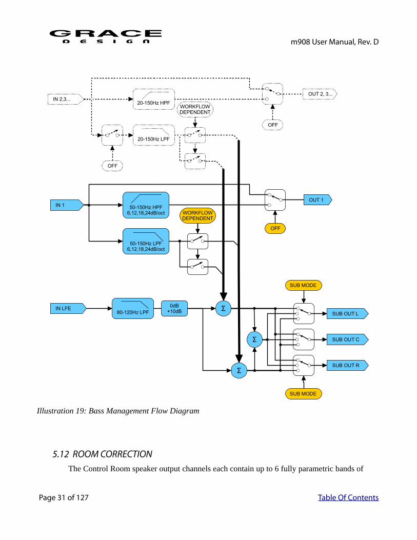
5.11 BASS MANAGEMENTThe m908 includes comprehensive Bass Management control. Each speaker in the Control
Room system can be individually configured for crossover frequency, high pass filter slope, and
Page 29 of 127 Table Of Contents
m908 User Manual, Rev. D
low pass filter slope. The internal summing of the LPF signals is done in stereo. All left channel speakers are added to the Left sub bus, right channel speakers are added to the Right sub bus, andcenter speakers are added to both busses equally. The user can decide to use stereo sub woofers or use a mono sum of the stereo bus.
The high pass and low pass filter slope options are:
• 24dB/octave Linkwitz-Riley
• 18dB/octave Butterworth
• 12dB/octave Linkwitz Riley (LPF Output inverted)
• 6dB/octave
The high pass filter can be bypassed so a full range signal is sent to the speaker. As well, the low pass filter can be turned off so that no signal is sent to the sub woofers.
The Bass Management system can be bypassed from the Monitor Control setup screen.
The LFE input channel contains a variable low pass filter and a 0 or +10dB gain setting. Theseare system level settings which are contained in the Monitor Control setup.
See the Monitor Control setup section of this manual for configuration details.
CAUTION: When enabling or disabling Bass Management in Monitor Control Setup it is recommended that you turn your Control Room volume down to 0.
Page 30 of 127 Table Of Contents
m908 User Manual, Rev. D
5.12 ROOM CORRECTIONThe Control Room speaker output channels each contain up to 6 fully parametric bands of
Page 31 of 127 Table Of Contents
Σ
IN 1OUT 1
50-150Hz LPF6,12,18,24dB/oct
SUB OUT LIN LFE
80-120Hz LPF
IN 2,3...OUT 2, 3...
ΣSUB OUT R
20-150Hz LPF
20-150Hz HPF
OFF
50-150Hz HPF6,12,18,24dB/oct
OFF
OFF
Σ SUB OUT C
SUB MODE
SUB MODE
WORKFLOWDEPENDENT
WORKFLOWDEPENDENT
0dB+10dB
Illustration 19: Bass Management Flow Diagram
m908 User Manual, Rev. D
equalization for correcting minor frequency response aberrations in your control room.
The SUB speakers will have 6 bands of eq per speaker (up to 3 subs can be used). The remaining speaker channels have 3 bands.
Each band of eq can be set for high pass, low pass, high shelf, low shelf, and peak response.
All room correction equalizers can be bypassed from the Monitor Control setup screen.
See the Room Correction setup section of this manual for details.
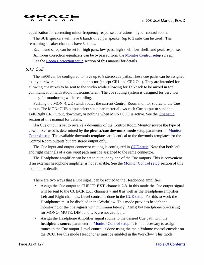
5.13 CUEThe m908 can be configured to have up to 8 stereo cue paths. These cue paths can be assigned
to any hardware input and output connector (except CR1 and CR2 Out). They are intended for allowing cue mixes to be sent to the studio while allowing for Talkback to be mixed in for communication with studio musicians/talent. The cue routing system is designed for very low latency for monitoring while recording.
Pushing the MON>CUE switch routes the current Control Room monitor source to the Cue output. The MON>CUE output select setup parameter allows each Cue output to send the Left/Right CR Output, downmix, or nothing when MON>CUE is active. See the Cue setup section of this manual for details.
If a Cue output is set to receive a downmix of the Control Room Monitor source the type of downmixer used is determined by the phones/cue downmix mode setup parameter in Monitor Control setup. The available downmix templates are identical to the downmix templates for the Control Room outputs but are stereo output only.
The Cue input and output connector routing is configured in CUE setup. Note that both left and right channels of a cue input path must be assigned to the same connector.
The Headphone amplifier can be set to output any one of the Cue outputs. This is convenient if an external headphone amplifier is not available. See the Monitor Control setup section of this manual for details.
There are two ways that a Cue signal can be routed to the Headphone amplifier:
• Assign the Cue output to CUE/CR EXT. channels 7-8. In this mode the Cue output signal will be sent to the CUE/CR EXT channels 7 and 8 as well as the Headphone amplifier Left and Right channels. Level control is done in the CUE setup. For this to work the Headphones must be disabled in the Workflow. This mode provides headphone monitoring of the cue signals with minimum latency (<1ms) but headphone processing for MONO, MUTE, DIM, and L-R are not available.
• Assign the Headphone Amplifier signal source to the desired Cue path with the headphone source parameter in Monitor Control setup. It is not necessary to assign routes to the Cue output. Level control is done using the main Volume control encoder on the RCU. For this mode Headphones must be enabled in the Workflow. This mode
Page 32 of 127 Table Of Contents
m908 User Manual, Rev. D
provides headphone monitoring of the cue signal and maintains RCU VOLUME control, MONO, MUTE, DIM, and L-R processing. However, there will be 4ms of latency from Cue in to headphones out.
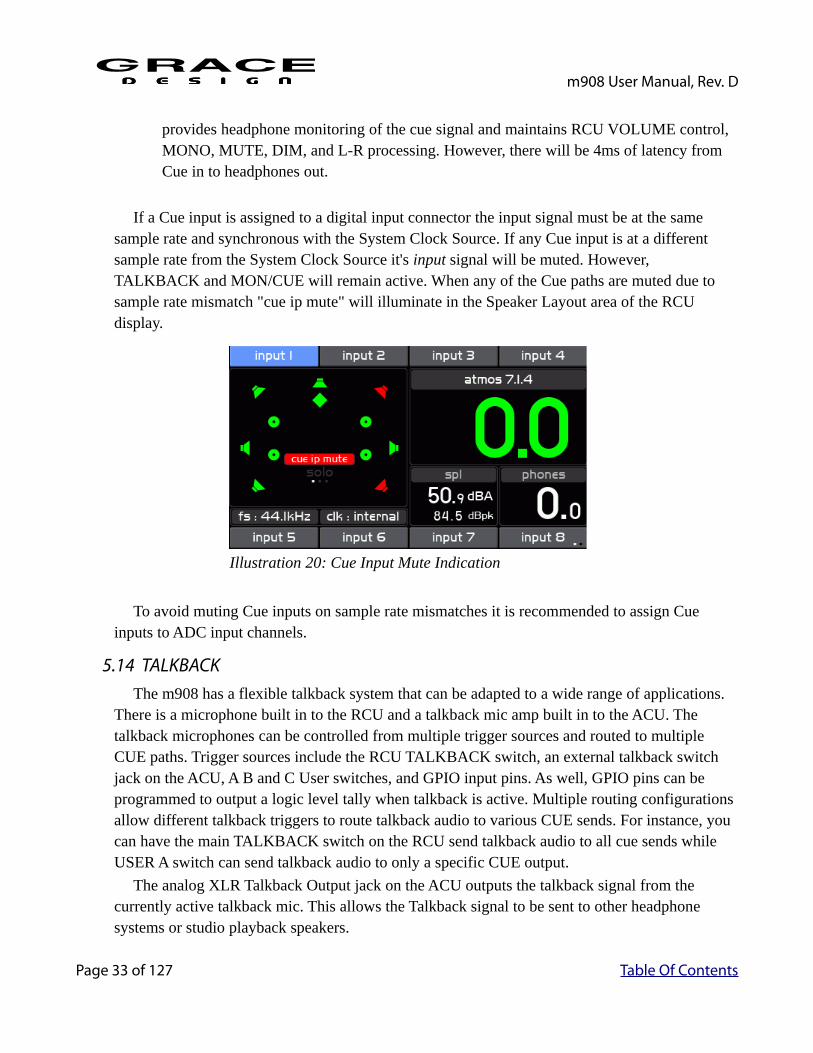
If a Cue input is assigned to a digital input connector the input signal must be at the same sample rate and synchronous with the System Clock Source. If any Cue input is at a different sample rate from the System Clock Source it's input signal will be muted. However, TALKBACK and MON/CUE will remain active. When any of the Cue paths are muted due to sample rate mismatch "cue ip mute" will illuminate in the Speaker Layout area of the RCU display.
To avoid muting Cue inputs on sample rate mismatches it is recommended to assign Cue inputs to ADC input channels.
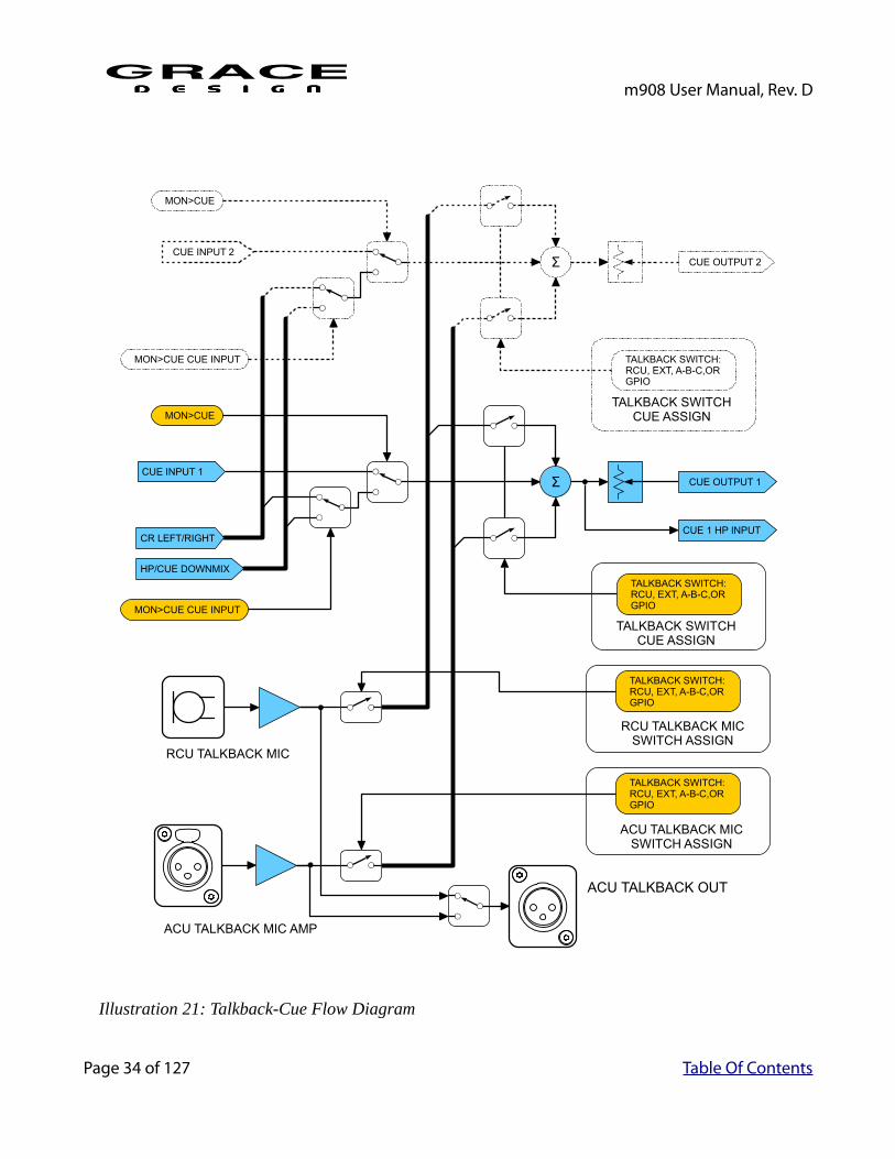
5.14 TALKBACKThe m908 has a flexible talkback system that can be adapted to a wide range of applications.
There is a microphone built in to the RCU and a talkback mic amp built in to the ACU. The talkback microphones can be controlled from multiple trigger sources and routed to multiple CUE paths. Trigger sources include the RCU TALKBACK switch, an external talkback switch jack on the ACU, A B and C User switches, and GPIO input pins. As well, GPIO pins can be programmed to output a logic level tally when talkback is active. Multiple routing configurations allow different talkback triggers to route talkback audio to various CUE sends. For instance, you can have the main TALKBACK switch on the RCU send talkback audio to all cue sends while USER A switch can send talkback audio to only a specific CUE output.
The analog XLR Talkback Output jack on the ACU outputs the talkback signal from the currently active talkback mic. This allows the Talkback signal to be sent to other headphone systems or studio playback speakers.
Page 33 of 127 Table Of Contents
Illustration 20: Cue Input Mute Indication
m908 User Manual, Rev. D
Page 34 of 127 Table Of Contents
CUE INPUT 1CUE OUTPUT 1
CUE INPUT 2CUE OUTPUT 2
RCU TALKBACK MIC
ACU TALKBACK MIC AMP
MON>CUE
MON>CUE
CR LEFT/RIGHT
Σ
TALKBACK SWITCHCUE ASSIGN
TALKBACK SWITCH:RCU, EXT, A-B-C,ORGPIO
RCU TALKBACK MICSWITCH ASSIGN
TALKBACK SWITCH:RCU, EXT, A-B-C,ORGPIO
ACU TALKBACK MICSWITCH ASSIGN
TALKBACK SWITCH:RCU, EXT, A-B-C,ORGPIO
TALKBACK SWITCHCUE ASSIGN
TALKBACK SWITCH:RCU, EXT, A-B-C,ORGPIO
Σ
ACU TALKBACK OUT
CUE 1 HP INPUT
HP/CUE DOWNMIX
MON>CUE CUE INPUT
MON>CUE CUE INPUT
Illustration 21: Talkback-Cue Flow Diagram
m908 User Manual, Rev. D
The TALKBACK, ABC, and external talkback switches use an automatic latch/momentary operation. A quick press-release will latch the talback mic on. Press-release again to turn talkbackoff. Pushing and holding the talkback switch will activate talkback only while the switch is being held down (momentary mode). When Talkback is activated by pressing the TALKBACK switch it will illuminate red. If Talkback has been activated by the ABC switches, External Talkback switch or a GPIO pin, the TALKBACK switch will flash RED.
See the Talkback setup section of this manual for configuration details
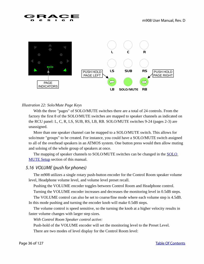
5.15 SOLO/MUTEThe nine bi-colored SOLO/MUTE switches are used to solo or mute any individual channel or
group of channels being monitored. Eight of the switches engage solo or mute for the relevant channel, while the solo/mute switch is used to toggle between solo or mute mode.
When in Solo mode the SOLO/MUTE switch will illuminate green. Pushing any of the 8 SOLO/MUTE switches will toggle solo mode on and off for that channel. In the speaker layout window the word "solo" will appear in green and channels that are not soloed will be grayed out.
When in Mute mode the SOLO/MUTE switch will illuminate red. Pushing any of the 8 SOLO/MUTE switches will toggle mute mode on and off for that channel. In the speaker layout window the word "mute" will appear in red and channels that are muted will be grayed out.
The SOLO/MUTE switches handle a complete 7.1 speaker system. However, if your speaker system has more than 8 channels the SOLO/MUTE switches can "page" to the higher order channels.
To page to higher order channels push-hold the RB switch. To page to lower order channels push-hold the LB switch. The current solo/mute page is indicated in the group of 3 small dots in the middle area of the speaker layout section of the LCD display. The current solo or mute mode is indicated right above the page dots.
Page 35 of 127 Table Of Contents
m908 User Manual, Rev. D
With the three "pages" of SOLO/MUTE switches there are a total of 24 controls. From the factory the first 8 of the SOLO/MUTE switches are mapped to speaker channels as indicated on the RCU panel: L, C, R, LS, SUB, RS, LB, RB. SOLO/MUTE switches 9-24 (pages 2-3) are unassigned.
More than one speaker channel can be mapped to a SOLO/MUTE switch. This allows for solo/mute "groups" to be created. For instance, you could have a SOLO/MUTE switch assigned to all of the overhead speakers in an ATMOS system. One button press would then allow muting and soloing of the whole group of speakers at once.
The mapping of speaker channels to SOLO/MUTE switches can be changed in the SOLO MUTE Setup section of this manual.
5.16 VOLUME (push for phones)The m908 utilizes a single rotary push-button encoder for the Control Room speaker volume
level, Headphone volume level, and volume level preset recall.
Pushing the VOLUME encoder toggles between Control Room and Headphone control.
Turning the VOLUME encoder increases and decreases the monitoring level in 0.5dB steps.
The VOLUME control can also be set to coarse/fine mode where each volume step is 4.5dB. In this mode pushing and turning the encoder knob will make 0.5dB steps.
The volume control is speed sensitive, so the turning the knob at a higher velocity results in faster volume changes with larger step sizes.
With Control Room Speaker control active:
Push-hold of the VOLUME encoder will set the monitoring level to the Preset Level.
There are two modes of level display for the Control Room level:
Page 36 of 127 Table Of Contents
L C R
RSLS SUB
RBSOLO/MUTELB
PAGEINDICATORS
PUSH HOLDPAGE LEFT
PUSH HOLDPAGE RIGHT
Illustration 22: Solo/Mute Page Keys
m908 User Manual, Rev. D
• Standard Mode The Control Room level range is 0-100 with 0 being mute and 96 being unity gain. With 0.5dB steps this is a 99.5dB attenuation range.
• Reference Mode The Control Room level readout can be scaled so that a calibrated monitoring level can be displayed as 0dB.
With Headphone control active:
Push-hold of the VOLUME encoder will set the monitoring level to the Preset Level.
See the Monitor Control setup section of this manual for configuration details.
5.17 A B C User SwitchesThe ABC User Switches are software definable and can be configured to control a variety of
system commands.
Available uses are additional talkback triggers, downmix control, and GPIO triggers.
See the A B C User Switches Setup section of this manual for configuration details.
When configured for Talkback the User switches will behave just like the dedicated Talkback switch and will illuminate RED when active.
When configured to be GPIO triggers the User switches will toggle on and off and illuminate GREEN when active.
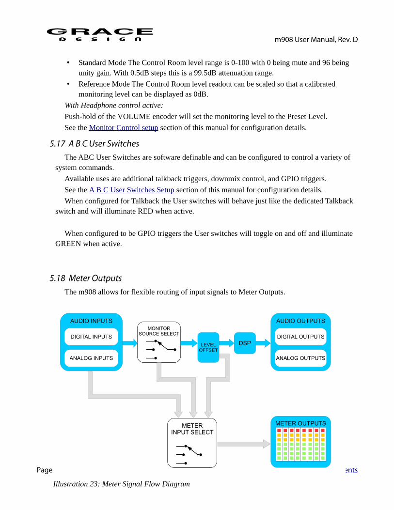
5.18 Meter OutputsThe m908 allows for flexible routing of input signals to Meter Outputs.
Page 37 of 127 Table Of Contents
AUDIO INPUTS
DIGITAL INPUTS
ANALOG INPUTS
MONITORSOURCE SELECT
DSP
METER OUTPUTSMETERINPUT SELECT
AUDIO OUTPUTS
DIGITAL OUTPUTS
ANALOG OUTPUTS
LEVELOFFSET
Illustration 23: Meter Signal Flow Diagram
m908 User Manual, Rev. D
The meter source options are:
• Audio Input source
This option fixes the Meter source to a specific input. The signal level is identical to the incoming signal level.
• Follow monitoring source selector pre level offset
This option allows the Meter source to follow whatever is being monitored on the ControlRoom speakers. The signal level is identical to the incoming signal level.
• Follow monitoring source selector post level offset
This option allows the Meter source to follow whatever is being monitored on the ControlRoom speakers. The signal level follows whatever input level offset is set for the currently selected input.
The Meter outputs can be assigned to any hardware output connector that is not being used by a Control Room speaker or a Cue output.
Note: CR1, CR2, and CR3 OUT can not be used for meter outputs.
See the Meter Output setup section of this manual for details on Meter Output routing.
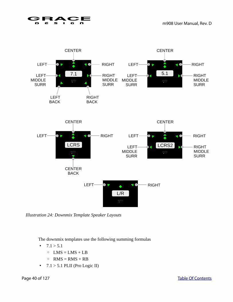
5.19 DownmixThe m908 contains two downmixers and a predefined set of downmix templates. The first
downmixer processes the input signal and outputs to the CR Outputs. The second downmixer processes the input signals and is available as a source to feed the Headphone and Cue outputs. This downmixer uses only stereo out templates and allows these stereo Cue and Headphone outputs to monitor a surround input source while simultaneously monitoring in surround on the CR Outputs. Each stereo output template contains downmix level parameters. These parameters are set to default Dolby metadata values in most cases. Downmix templates are accessed by configuring one of the A,B, or C User switches to activate a downmix.
To enable a downmix mixer one of the A, B, or C User switches must be assigned to downmixmode with a downmix template selected. See the A B C User Switches Setup section of this manual for details.
Up to three downmix templates can be used by assigning each A, B, and C switches to a downmix template.
The CR Output downmix templates can be activated by assigning one of the ABC switches to the downmix function. See the A B C User Switches Setup section of this manual for details.
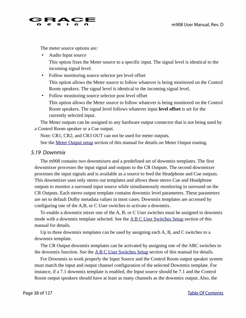
For Downmix to work properly the Input Source and the Control Room output speaker systemmust match the input and output channel configuration of the selected Downmix template. For instance, if a 7.1 downmix template is enabled, the Input source should be 7.1 and the Control Room output speakers should have at least as many channels as the downmix output. Also, the
Page 38 of 127 Table Of Contents
m908 User Manual, Rev. D
Workflow must contain a speaker layout using the names below. The INPUT and CR output mustbe routed to these speaker names.
Speaker Channels for Downmix OperationSpeaker Name AbbreviationLEFT L
CENTER CRIGHT R
LEFT MIDDLE SURR LMSRIGHT MIDDLE SURR RMS
LEFT BACK LBRIGHT BACK RB
CENTER BACK CB
Page 39 of 127 Table Of Contents
m908 User Manual, Rev. D
The downmix templates use the following summing formulas
• 7.1 > 5.1
LMS = LMS + LB
RMS = RMS + RB
• 7.1 > 5.1 PLII (Pro Logic II)
Page 40 of 127 Table Of Contents
CENTER
LEFT RIGHT
CENTERBACK
LCRS
CENTER
LEFT RIGHT
RIGHTMIDDLESURR
LEFTMIDDLE
SURR
LCRS2
RIGHT
L/R
LEFT
7.1
CENTER
LEFT RIGHT
RIGHTMIDDLESURR
LEFTBACK
RIGHTBACK
LEFTMIDDLE
SURR
5.1
CENTER
LEFT RIGHT
RIGHTMIDDLESURR
LEFTMIDDLE
SURR
Illustration 24: Downmix Template Speaker Layouts
m908 User Manual, Rev. D
LMS = LMS + (–1.2dB x LB) + (–6.2dB x RB)
RMS = RMS + (–6.2dB x LB) + (–1.2dB x RB)
• 7.1 to LCRS
CB = (-3dB x (LMS + LB)) +(-3dB x (RMS + RB))
• 7.1 to LCRS2
LMS = (-6dB x (LMS + LB)) +(-6dB x (RMS + RB))
RMS = (-6dB x (LMS + LB)) +(-6dB x (RMS + RB))
• 7.1 > Lt/Rt
L = L + (–3 dB x C) – (–3 dB x (LMS + LB)) – (–3 dB x (RMS + RB))
R = R + (–3 dB x C) + (–3 dB x (LMS + LB)) + (–3 dB x (RMS + RB))
• 7.1 > Lt/Rt PLII (Pro Logic II)
L = L + (–3 dB x C) – (–1.2 dB x (LMS + LB)) – (–6.2 dB x (RMS + RB))
R = R + (–3 dB x C) + (–6.2 dB x (LMS + LB)) + (–1.2dB x (RMS + RB))
• 7.1 > Lo/Ro
L = L + (–3 dB x C) + (–3 dB x (LMS + LB))
R = R + (–3 dB x C) + (–3 dB x (RMS + RB))
• 5.1 to LCRS
CB = (-3dB x LMS) + (-3dB x RMS)
• 5.1 to LCRS2
LMS = (-6dB x LMS) + (-6dB x RMS)
RMS = (-6dB x LMS) + (-6dB x RMS)
• 5.1 to Lt/Rt:
L = L + (–3 dB x C) – (–3 dB x LMS) – (–3 dB x RMS)
R = R + (–3 dB x C) + (–3 dB x LMS) + (–3 dB x RMS)
• 5.1 to Lt/Rt (Pro Logic II)
L = L + (–3 dB x C) – (–1.2 dB x LMS) – (–6.2 dB x RMS)
R = R + (–3 dB x C) + (–6.2 dB x LMS) + (–1.2 dB x RMS)
• 5.1 to Lo/Ro
L = L + (–3 dB x C) + (–3 dB x LMS)
R = R + (–3 dB x C) + (–3 dB x RMS)
• LCRS to L/R
L = L + (–3 dB x C) + (–3 dB x CB)
R = R + (–3 dB x C) + (–3 dB x CB)
• LCRS2 to L/R
L = L + (–3 dB x C) + (–3 dB x LMS)
Page 41 of 127 Table Of Contents
m908 User Manual, Rev. D
R = R + (–3 dB x C) + (–3 dB x RMS)
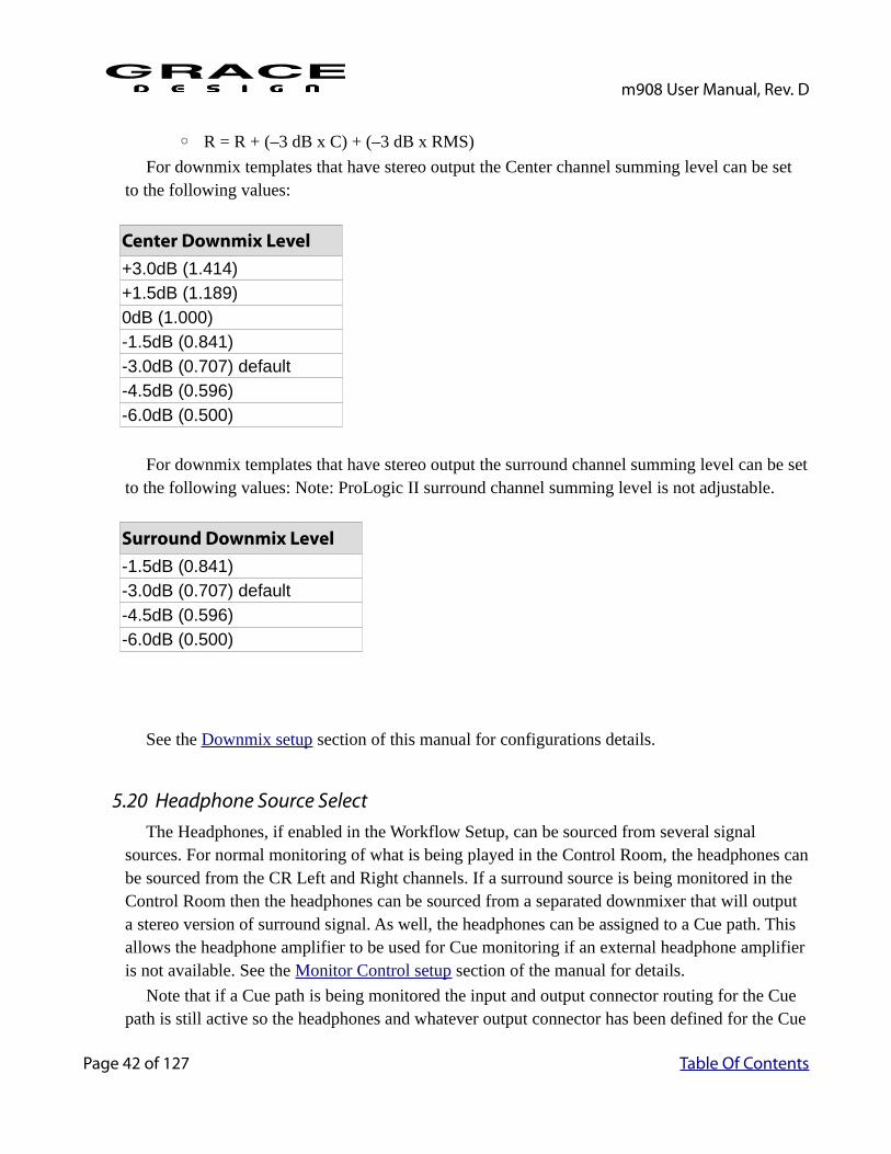
For downmix templates that have stereo output the Center channel summing level can be set to the following values:
Center Downmix Level+3.0dB (1.414)+1.5dB (1.189)
0dB (1.000)-1.5dB (0.841)
-3.0dB (0.707) default-4.5dB (0.596)
-6.0dB (0.500)
For downmix templates that have stereo output the surround channel summing level can be setto the following values: Note: ProLogic II surround channel summing level is not adjustable.
Surround Downmix Level-1.5dB (0.841)-3.0dB (0.707) default
-4.5dB (0.596)-6.0dB (0.500)
See the Downmix setup section of this manual for configurations details.
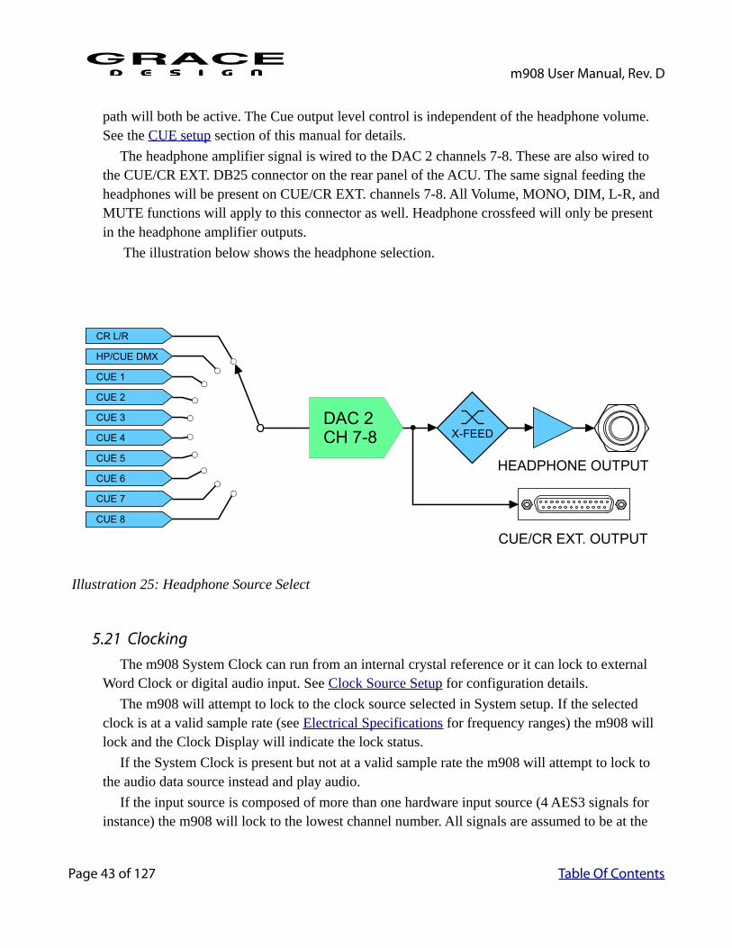
5.20 Headphone Source SelectThe Headphones, if enabled in the Workflow Setup, can be sourced from several signal
sources. For normal monitoring of what is being played in the Control Room, the headphones canbe sourced from the CR Left and Right channels. If a surround source is being monitored in the Control Room then the headphones can be sourced from a separated downmixer that will output a stereo version of surround signal. As well, the headphones can be assigned to a Cue path. This allows the headphone amplifier to be used for Cue monitoring if an external headphone amplifieris not available. See the Monitor Control setup section of the manual for details.
Note that if a Cue path is being monitored the input and output connector routing for the Cue path is still active so the headphones and whatever output connector has been defined for the Cue
Page 42 of 127 Table Of Contents
m908 User Manual, Rev. D
path will both be active. The Cue output level control is independent of the headphone volume. See the CUE setup section of this manual for details.
The headphone amplifier signal is wired to the DAC 2 channels 7-8. These are also wired to the CUE/CR EXT. DB25 connector on the rear panel of the ACU. The same signal feeding the headphones will be present on CUE/CR EXT. channels 7-8. All Volume, MONO, DIM, L-R, and MUTE functions will apply to this connector as well. Headphone crossfeed will only be present in the headphone amplifier outputs.
The illustration below shows the headphone selection.
5.21 ClockingThe m908 System Clock can run from an internal crystal reference or it can lock to external
Word Clock or digital audio input. See Clock Source Setup for configuration details.
The m908 will attempt to lock to the clock source selected in System setup. If the selected clock is at a valid sample rate (see Electrical Specifications for frequency ranges) the m908 will lock and the Clock Display will indicate the lock status.
If the System Clock is present but not at a valid sample rate the m908 will attempt to lock to the audio data source instead and play audio.
If the input source is composed of more than one hardware input source (4 AES3 signals for instance) the m908 will lock to the lowest channel number. All signals are assumed to be at the
Page 43 of 127 Table Of Contents
DAC 2CH 7-8
HEADPHONE OUTPUT
CR L/R
HP/CUE DMX
CUE 1
CUE 2
CUE 3
CUE 4
CUE 5
CUE 6
CUE 7
CUE 8
CUE/CR EXT. OUTPUT
X-FEED
Illustration 25: Headphone Source Select
m908 User Manual, Rev. D
same sample rate and synchronous to each other. If there are mismatched sample rates among theinput signals for the input source then audio will be muted and the system clock status will flash red.
The m908 does not contain a sample rate converter. If the clock source is set to a connector that is not the same as the audio data source then it is assumed that the audio data will be at the same sample rate and be synchronous to the clock source.
If the m908 system clock source is set to one of the Internal sample rates then the m908 is the clock master. Any digital audio source connected to the m908 will need to be synchronized to them908 word clock output.
If there is a digital input source that can not be synchronized to an external clock (CD player for instance) then set the override clock in the Input Setup for that device. When that input is selected for monitoring, the System Clock will switch the clock source to that input audio stream automatically. See the Input Setup section of this manual for details.
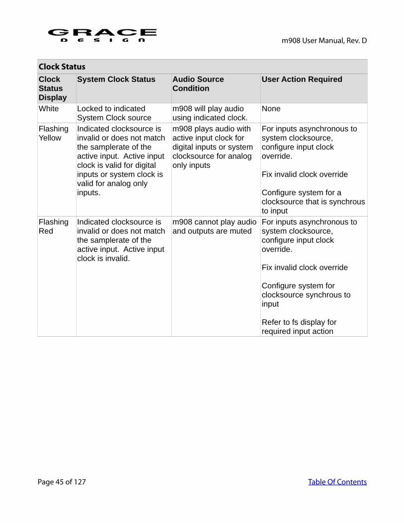
Below are two tables that summarize the various clock and sample rate states that are indicated by the fs: and clk: displays on the RCU.
Page 44 of 127 Table Of Contents
m908 User Manual, Rev. D
Clock StatusClock Status Display
System Clock Status Audio Source Condition
User Action Required
White Locked to indicated System Clock source
m908 will play audio using indicated clock.
None
Flashing Yellow
Indicated clocksource is invalid or does not match the samplerate of the active input. Active input clock is valid for digital inputs or system clock is valid for analog only inputs.
m908 plays audio with active input clock for digital inputs or system clocksource for analog only inputs
For inputs asynchronous to system clocksource, configure input clock override.
Fix invalid clock override
Configure system for a clocksource that is synchrousto input
Flashing Red
Indicated clocksource is invalid or does not match the samplerate of the active input. Active input clock is invalid.
m908 cannot play audio and outputs are muted
For inputs asynchronous to system clocksource, configure input clock override.
Fix invalid clock override
Configure system for clocksource synchrous to input
Refer to fs display for required input action
Page 45 of 127 Table Of Contents
m908 User Manual, Rev. D
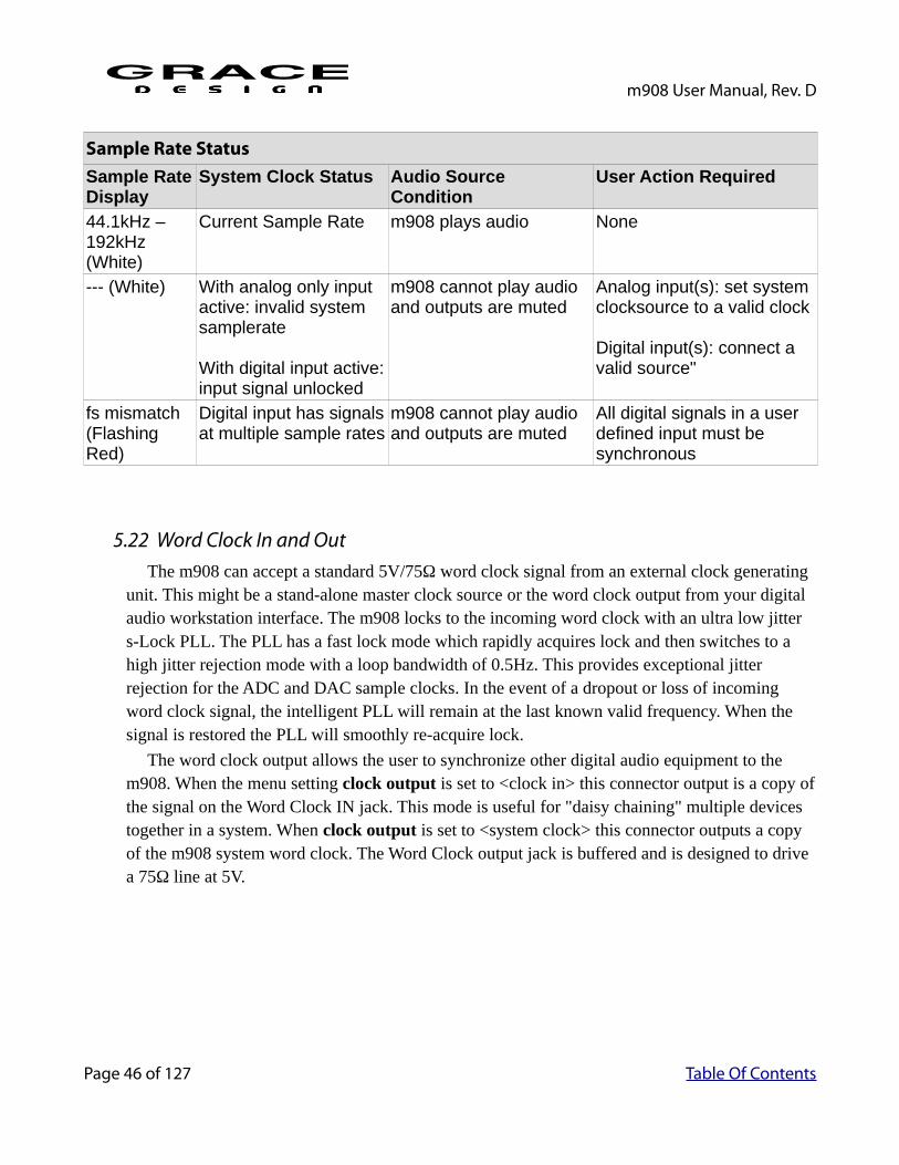
Sample Rate StatusSample RateDisplay
System Clock Status Audio Source Condition
User Action Required
44.1kHz – 192kHz (White)
Current Sample Rate m908 plays audio None
--- (White) With analog only input active: invalid system samplerate
With digital input active:input signal unlocked
m908 cannot play audio and outputs are muted
Analog input(s): set system clocksource to a valid clock
Digital input(s): connect a valid source"
fs mismatch (Flashing Red)
Digital input has signalsat multiple sample rates
m908 cannot play audio and outputs are muted
All digital signals in a user defined input must be synchronous
5.22 Word Clock In and OutThe m908 can accept a standard 5V/75Ω word clock signal from an external clock generating
unit. This might be a stand-alone master clock source or the word clock output from your digital audio workstation interface. The m908 locks to the incoming word clock with an ultra low jitter s-Lock PLL. The PLL has a fast lock mode which rapidly acquires lock and then switches to a high jitter rejection mode with a loop bandwidth of 0.5Hz. This provides exceptional jitter rejection for the ADC and DAC sample clocks. In the event of a dropout or loss of incoming word clock signal, the intelligent PLL will remain at the last known valid frequency. When the signal is restored the PLL will smoothly re-acquire lock.
The word clock output allows the user to synchronize other digital audio equipment to the m908. When the menu setting clock output is set to <clock in> this connector output is a copy ofthe signal on the Word Clock IN jack. This mode is useful for "daisy chaining" multiple devices together in a system. When clock output is set to <system clock> this connector outputs a copy of the m908 system word clock. The Word Clock output jack is buffered and is designed to drive a 75Ω line at 5V.
Page 46 of 127 Table Of Contents
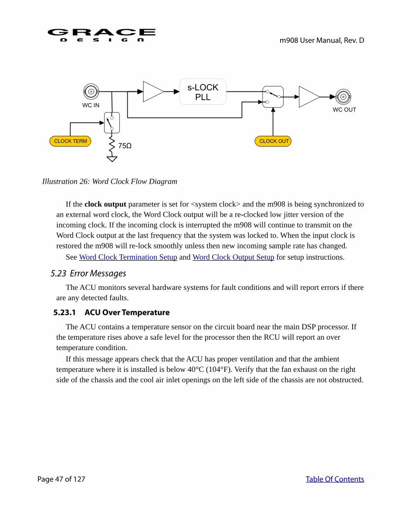
m908 User Manual, Rev. D
If the clock output parameter is set for <system clock> and the m908 is being synchronized toan external word clock, the Word Clock output will be a re-clocked low jitter version of the incoming clock. If the incoming clock is interrupted the m908 will continue to transmit on the Word Clock output at the last frequency that the system was locked to. When the input clock is restored the m908 will re-lock smoothly unless then new incoming sample rate has changed.
See Word Clock Termination Setup and Word Clock Output Setup for setup instructions.
5.23 Error MessagesThe ACU monitors several hardware systems for fault conditions and will report errors if there
are any detected faults.
5.23.1 ACU Over Temperature
The ACU contains a temperature sensor on the circuit board near the main DSP processor. If the temperature rises above a safe level for the processor then the RCU will report an over temperature condition.
If this message appears check that the ACU has proper ventilation and that the ambient temperature where it is installed is below 40°C (104°F). Verify that the fan exhaust on the right side of the chassis and the cool air inlet openings on the left side of the chassis are not obstructed.
Page 47 of 127 Table Of Contents
Illustration 26: Word Clock Flow Diagram
WC INWC OUT
75ΩCLOCK TERM CLOCK OUT
s-LOCKPLL
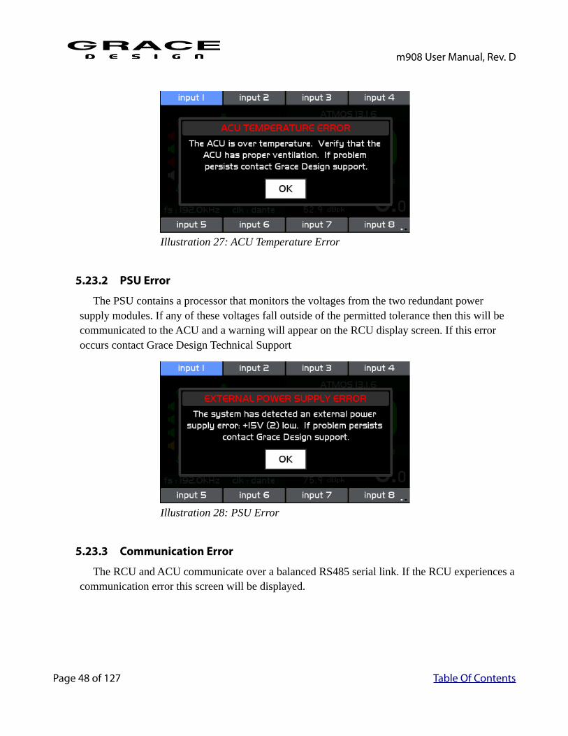
m908 User Manual, Rev. D
5.23.2 PSU Error
The PSU contains a processor that monitors the voltages from the two redundant power supply modules. If any of these voltages fall outside of the permitted tolerance then this will be communicated to the ACU and a warning will appear on the RCU display screen. If this error occurs contact Grace Design Technical Support
5.23.3 Communication Error
The RCU and ACU communicate over a balanced RS485 serial link. If the RCU experiences acommunication error this screen will be displayed.
Page 48 of 127 Table Of Contents
Illustration 27: ACU Temperature Error
Illustration 28: PSU Error
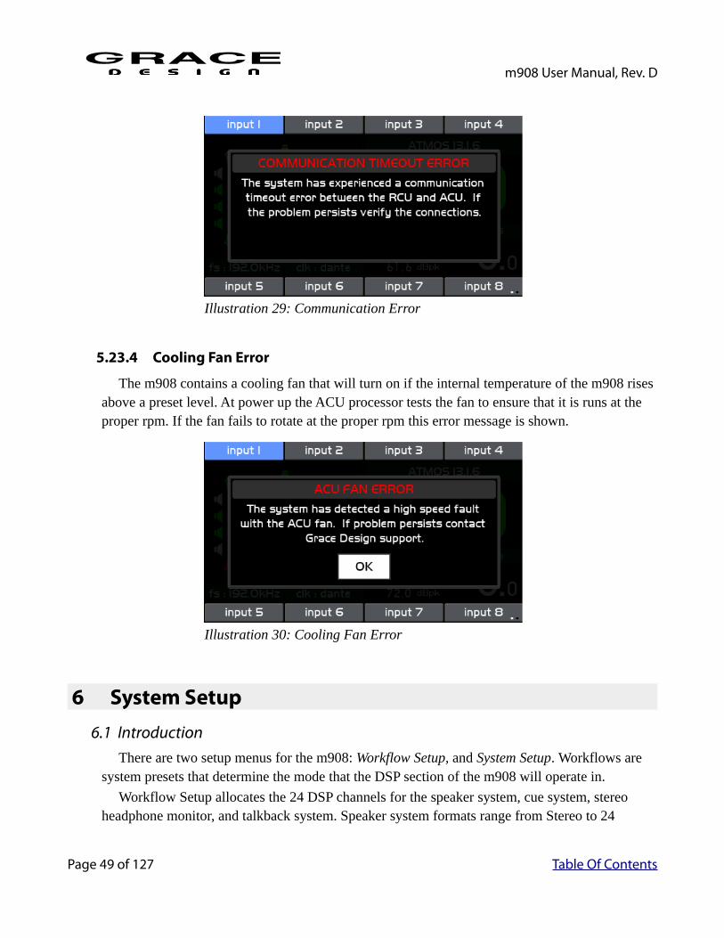
m908 User Manual, Rev. D
5.23.4 Cooling Fan Error
The m908 contains a cooling fan that will turn on if the internal temperature of the m908 rises above a preset level. At power up the ACU processor tests the fan to ensure that it is runs at the proper rpm. If the fan fails to rotate at the proper rpm this error message is shown.
6 System Setup 6.1 Introduction
There are two setup menus for the m908: Workflow Setup, and System Setup. Workflows are system presets that determine the mode that the DSP section of the m908 will operate in.
Workflow Setup allocates the 24 DSP channels for the speaker system, cue system, stereo headphone monitor, and talkback system. Speaker system formats range from Stereo to 24
Page 49 of 127 Table Of Contents
Illustration 29: Communication Error
Illustration 30: Cooling Fan Error
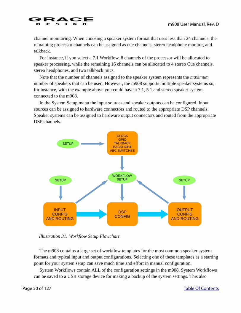
m908 User Manual, Rev. D
channel monitoring. When choosing a speaker system format that uses less than 24 channels, the remaining processor channels can be assigned as cue channels, stereo headphone monitor, and talkback.
For instance, if you select a 7.1 Workflow, 8 channels of the processor will be allocated to speaker processing, while the remaining 16 channels can be allocated to 4 stereo Cue channels, stereo headphones, and two talkback mics.
Note that the number of channels assigned to the speaker system represents the maximum number of speakers that can be used. However, the m908 supports multiple speaker systems so, for instance, with the example above you could have a 7.1, 5.1 and stereo speaker system connected to the m908.
In the System Setup menu the input sources and speaker outputs can be configured. Input sources can be assigned to hardware connectors and routed to the appropriate DSP channels. Speaker systems can be assigned to hardware output connectors and routed from the appropriate DSP channels.
The m908 contains a large set of workflow templates for the most common speaker system formats and typical input and output configurations. Selecting one of these templates as a startingpoint for your system setup can save much time and effort in manual configuration.
System Workflows contain ALL of the configuration settings in the m908. System Workflows can be saved to a USB storage device for making a backup of the system settings. This also
Page 50 of 127 Table Of Contents
INPUTCONFIG
AND ROUTING
DSPCONFIG
OUTPUTCONFIG
AND ROUTING
WORKFLOWSETUPSETUP SETUP
CLOCKGPIO
TALKBACKBACKLIGHT
ABC SWITCHES
SETUP
Illustration 31: Workflow Setup Flowchart
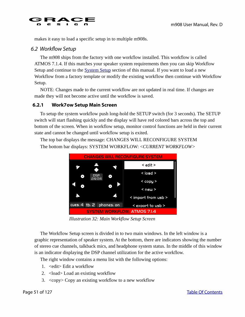
m908 User Manual, Rev. D
makes it easy to load a specific setup in to multiple m908s.
6.2 Workfow SetupThe m908 ships from the factory with one workflow installed. This workflow is called
ATMOS 7.1.4. If this matches your speaker system requirements then you can skip Workflow Setup and continue to the System Setup section of this manual. If you want to load a new Workflow from a factory template or modify the existing workflow then continue with WorkflowSetup.
NOTE: Changes made to the current workflow are not updated in real time. If changes are made they will not become active until the workflow is saved.
6.2.1 Workfow Setup Main Screen
To setup the system workflow push long-hold the SETUP switch (for 3 seconds). The SETUP switch will start flashing quickly and the display will have red colored bars across the top and bottom of the screen. When in workflow setup, monitor control functions are held in their currentstate and cannot be changed until workflow setup is exited.
The top bar displays the message: CHANGES WILL RECONFIGURE SYSTEM
The bottom bar displays: SYSTEM WORKFLOW: <CURRENT WORKFLOW>
The Workflow Setup screen is divided in to two main windows. In the left window is a graphic representation of speaker system. At the bottom, there are indicators showing the numberof stereo cue channels, talkback mics, and headphone system status. In the middle of this windowis an indicator displaying the DSP channel utilization for the active workflow.
The right window contains a menu list with the following options:
1. <edit> Edit a workflow
2. <load> Load an existing workflow
3. <copy> Copy an existing workflow to a new workflow
Page 51 of 127 Table Of Contents
Illustration 32: Main Workflow Setup Screen
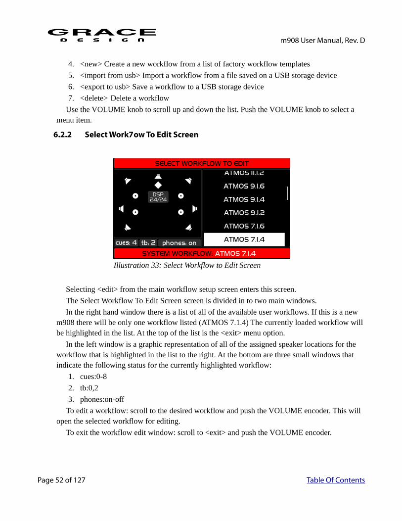
m908 User Manual, Rev. D
4. <new> Create a new workflow from a list of factory workflow templates
5. <import from usb> Import a workflow from a file saved on a USB storage device
6. <export to usb> Save a workflow to a USB storage device
7. <delete> Delete a workflow
Use the VOLUME knob to scroll up and down the list. Push the VOLUME knob to select a menu item.
6.2.2 Select Workfow To Edit Screen
Selecting <edit> from the main workflow setup screen enters this screen.
The Select Workflow To Edit Screen screen is divided in to two main windows.
In the right hand window there is a list of all of the available user workflows. If this is a new m908 there will be only one workflow listed (ATMOS 7.1.4) The currently loaded workflow will be highlighted in the list. At the top of the list is the <exit> menu option.
In the left window is a graphic representation of all of the assigned speaker locations for the workflow that is highlighted in the list to the right. At the bottom are three small windows that indicate the following status for the currently highlighted workflow:
1. cues:0-8
2. tb:0,2
3. phones:on-off
To edit a workflow: scroll to the desired workflow and push the VOLUME encoder. This will open the selected workflow for editing.
To exit the workflow edit window: scroll to <exit> and push the VOLUME encoder.
Page 52 of 127 Table Of Contents
Illustration 33: Select Workflow to Edit Screen
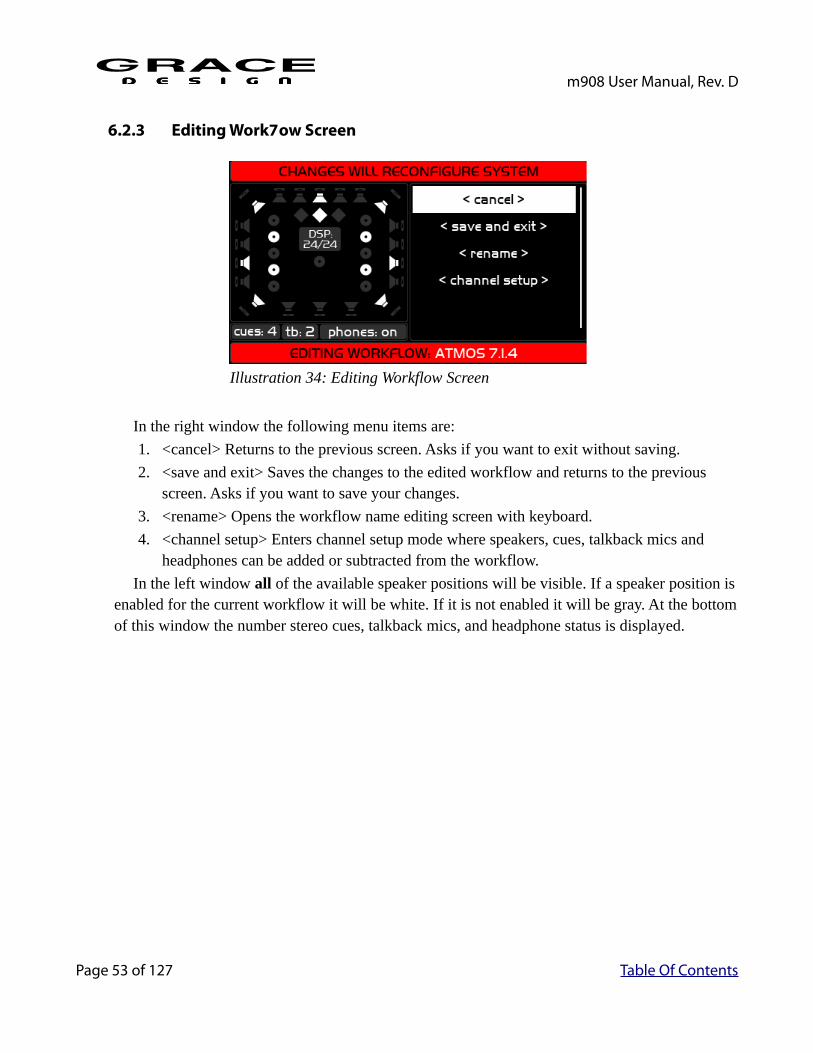
m908 User Manual, Rev. D
6.2.3 Editing Workfow Screen
In the right window the following menu items are:
1. <cancel> Returns to the previous screen. Asks if you want to exit without saving.
2. <save and exit> Saves the changes to the edited workflow and returns to the previous screen. Asks if you want to save your changes.
3. <rename> Opens the workflow name editing screen with keyboard.
4. <channel setup> Enters channel setup mode where speakers, cues, talkback mics and headphones can be added or subtracted from the workflow.
In the left window all of the available speaker positions will be visible. If a speaker position isenabled for the current workflow it will be white. If it is not enabled it will be gray. At the bottomof this window the number stereo cues, talkback mics, and headphone status is displayed.
Page 53 of 127 Table Of Contents
Illustration 34: Editing Workflow Screen
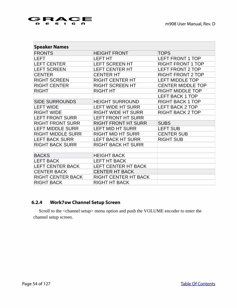
m908 User Manual, Rev. D
Speaker NamesFRONTS HEIGHT FRONT TOPS LEFT LEFT HT LEFT FRONT 1 TOP LEFT CENTER LEFT SCREEN HT RIGHT FRONT 1 TOPLEFT SCREEN LEFT CENTER HT LEFT FRONT 2 TOP CENTER CENTER HT RIGHT FRONT 2 TOPRIGHT SCREEN RIGHT CENTER HT LEFT MIDDLE TOP RIGHT CENTER RIGHT SCREEN HT CENTER MIDDLE TOPRIGHT RIGHT HT RIGHT MIDDLE TOP
LEFT BACK 1 TOPSIDE SURROUNDS HEIGHT SURROUND RIGHT BACK 1 TOPLEFT WIDE LEFT WIDE HT SURR LEFT BACK 2 TOPRIGHT WIDE RIGHT WIDE HT SURR RIGHT BACK 2 TOPLEFT FRONT SURR LEFT FRONT HT SURRRIGHT FRONT SURR RIGHT FRONT HT SURR SUBS LEFT MIDDLE SURR LEFT MID HT SURR LEFT SUBRIGHT MIDDLE SURR RIGHT MID HT SURR CENTER SUBLEFT BACK SURR LEFT BACK HT SURR RIGHT SUBRIGHT BACK SURR RIGHT BACK HT SURR
BACKS HEIGHT BACK LEFT BACK LEFT HT BACKLEFT CENTER BACK LEFT CENTER HT BACKCENTER BACK CENTER HT BACKRIGHT CENTER BACK RIGHT CENTER HT BACKRIGHT BACK RIGHT HT BACK
6.2.4 Workfow Channel Setup Screen
Scroll to the <channel setup> menu option and push the VOLUME encoder to enter the channel setup screen.
Page 54 of 127 Table Of Contents
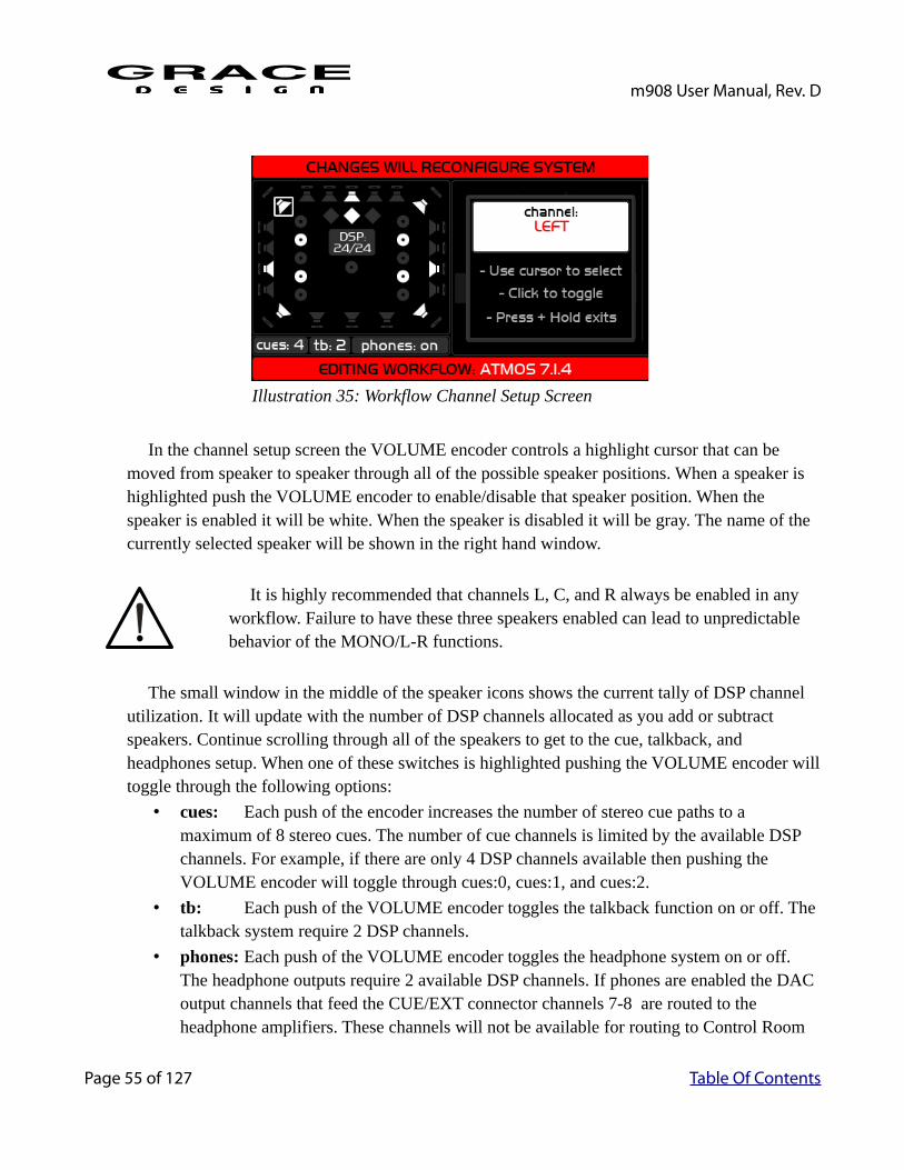
m908 User Manual, Rev. D
In the channel setup screen the VOLUME encoder controls a highlight cursor that can be moved from speaker to speaker through all of the possible speaker positions. When a speaker is highlighted push the VOLUME encoder to enable/disable that speaker position. When the speaker is enabled it will be white. When the speaker is disabled it will be gray. The name of the currently selected speaker will be shown in the right hand window.
It is highly recommended that channels L, C, and R always be enabled in any workflow. Failure to have these three speakers enabled can lead to unpredictable behavior of the MONO/L-R functions.
The small window in the middle of the speaker icons shows the current tally of DSP channel utilization. It will update with the number of DSP channels allocated as you add or subtract speakers. Continue scrolling through all of the speakers to get to the cue, talkback, and headphones setup. When one of these switches is highlighted pushing the VOLUME encoder willtoggle through the following options:
• cues: Each push of the encoder increases the number of stereo cue paths to a maximum of 8 stereo cues. The number of cue channels is limited by the available DSP channels. For example, if there are only 4 DSP channels available then pushing the VOLUME encoder will toggle through cues:0, cues:1, and cues:2.
• tb: Each push of the VOLUME encoder toggles the talkback function on or off. The talkback system require 2 DSP channels.
• phones: Each push of the VOLUME encoder toggles the headphone system on or off. The headphone outputs require 2 available DSP channels. If phones are enabled the DAC output channels that feed the CUE/EXT connector channels 7-8 are routed to the headphone amplifiers. These channels will not be available for routing to Control Room
Page 55 of 127 Table Of Contents
Illustration 35: Workflow Channel Setup Screen
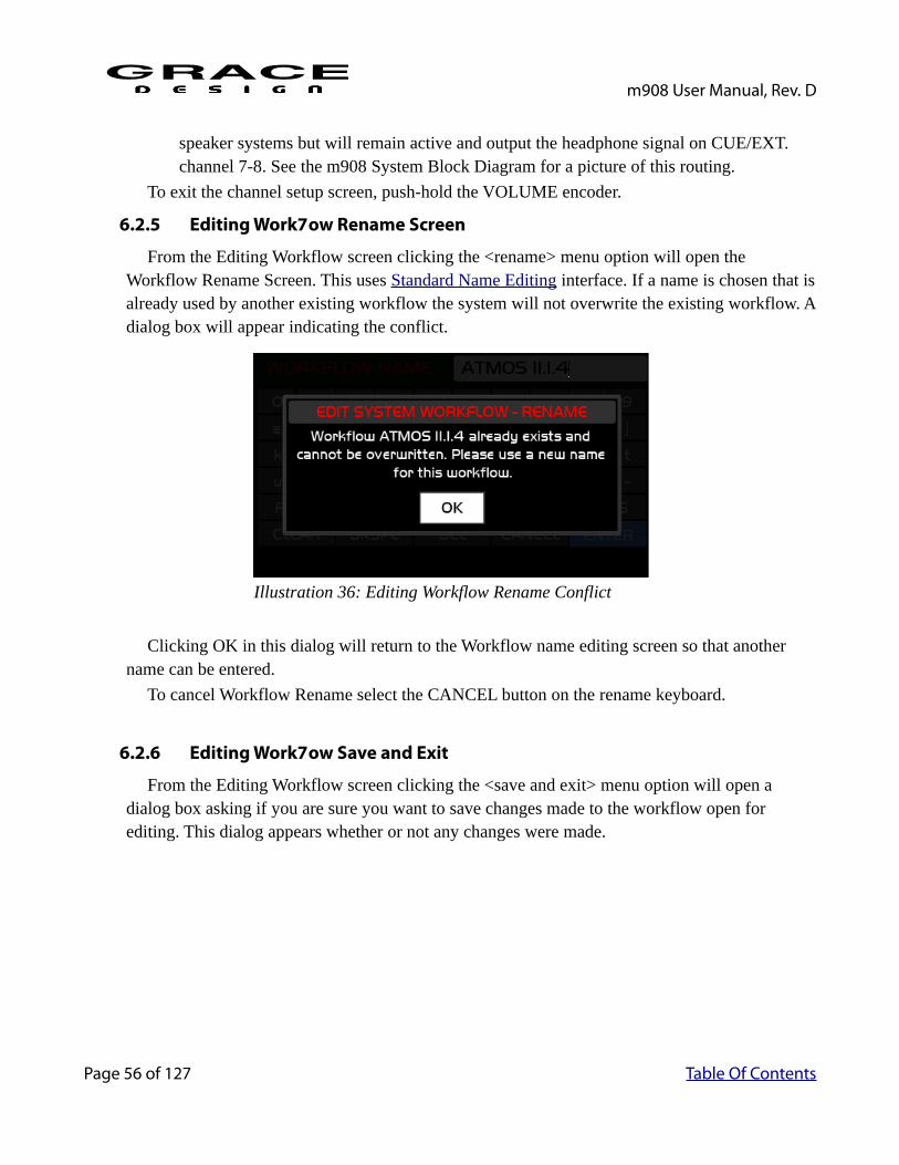
m908 User Manual, Rev. D
speaker systems but will remain active and output the headphone signal on CUE/EXT. channel 7-8. See the m908 System Block Diagram for a picture of this routing.
To exit the channel setup screen, push-hold the VOLUME encoder.
6.2.5 Editing Workfow Rename Screen
From the Editing Workflow screen clicking the <rename> menu option will open the Workflow Rename Screen. This uses Standard Name Editing interface. If a name is chosen that isalready used by another existing workflow the system will not overwrite the existing workflow. Adialog box will appear indicating the conflict.
Clicking OK in this dialog will return to the Workflow name editing screen so that another name can be entered.
To cancel Workflow Rename select the CANCEL button on the rename keyboard.
6.2.6 Editing Workfow Save and Exit
From the Editing Workflow screen clicking the <save and exit> menu option will open a dialog box asking if you are sure you want to save changes made to the workflow open for editing. This dialog appears whether or not any changes were made.
Page 56 of 127 Table Of Contents
Illustration 36: Editing Workflow Rename Conflict
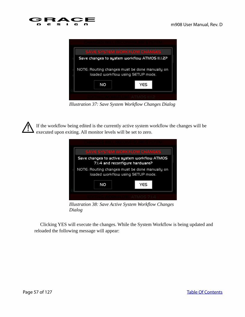
m908 User Manual, Rev. D
If the workflow being edited is the currently active system workflow the changes will be executed upon exiting. All monitor levels will be set to zero.
Clicking YES will execute the changes. While the System Workflow is being updated and reloaded the following message will appear:
Page 57 of 127 Table Of Contents
Illustration 37: Save System Workflow Changes Dialog
Illustration 38: Save Active System Workflow Changes Dialog
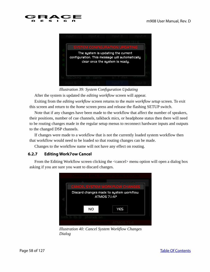
m908 User Manual, Rev. D
After the system is updated the editing workflow screen will appear.
Exiting from the editing workflow screen returns to the main workflow setup screen. To exit this screen and return to the home screen press and release the flashing SETUP switch.
Note that if any changes have been made to the workflow that affect the number of speakers, their positions, number of cue channels, talkback mics, or headphone status then there will need to be routing changes made in the regular setup menus to reconnect hardware inputs and outputs to the changed DSP channels.
If changes were made to a workflow that is not the currently loaded system workflow then that workflow would need to be loaded so that routing changes can be made.
Changes to the workflow name will not have any effect on routing.
6.2.7 Editing Workfow Cancel
From the Editing Workflow screen clicking the <cancel> menu option will open a dialog box asking if you are sure you want to discard changes.
Page 58 of 127 Table Of Contents
Illustration 40: Cancel System Workflow Changes Dialog
Illustration 39: System Configuration Updating
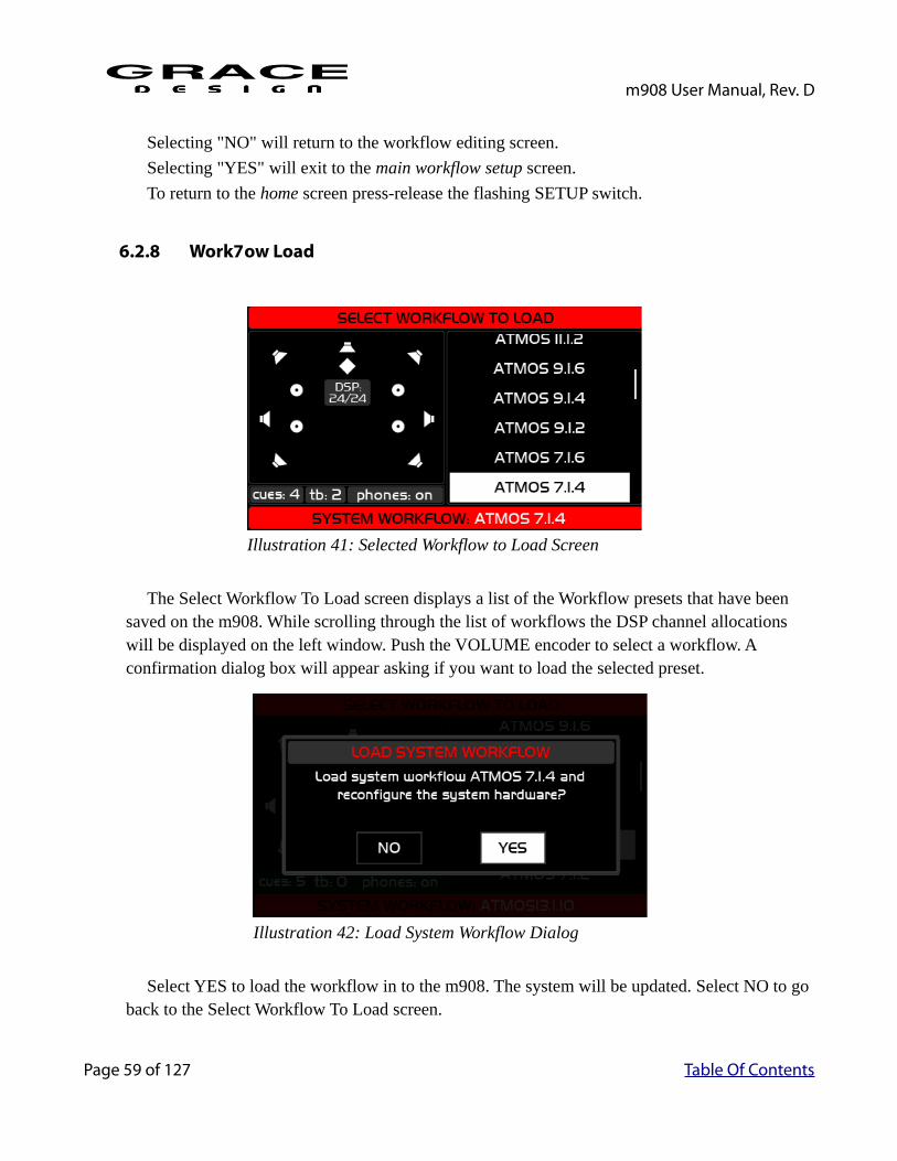
m908 User Manual, Rev. D
Selecting "NO" will return to the workflow editing screen.
Selecting "YES" will exit to the main workflow setup screen.
To return to the home screen press-release the flashing SETUP switch.
6.2.8 Workfow Load
The Select Workflow To Load screen displays a list of the Workflow presets that have been saved on the m908. While scrolling through the list of workflows the DSP channel allocations will be displayed on the left window. Push the VOLUME encoder to select a workflow. A confirmation dialog box will appear asking if you want to load the selected preset.
Select YES to load the workflow in to the m908. The system will be updated. Select NO to go back to the Select Workflow To Load screen.
Page 59 of 127 Table Of Contents
Illustration 41: Selected Workflow to Load Screen
Illustration 42: Load System Workflow Dialog
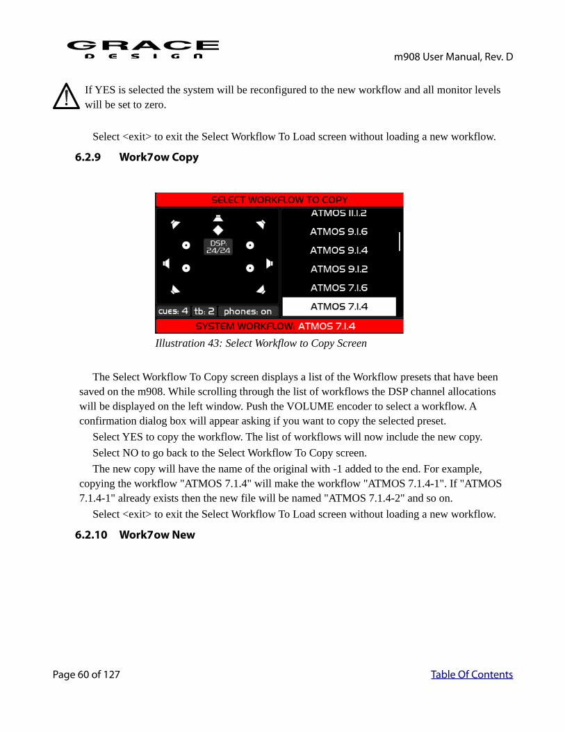
m908 User Manual, Rev. D
If YES is selected the system will be reconfigured to the new workflow and all monitor levels will be set to zero.
Select <exit> to exit the Select Workflow To Load screen without loading a new workflow.
6.2.9 Workfow Copy
The Select Workflow To Copy screen displays a list of the Workflow presets that have been saved on the m908. While scrolling through the list of workflows the DSP channel allocations will be displayed on the left window. Push the VOLUME encoder to select a workflow. A confirmation dialog box will appear asking if you want to copy the selected preset.
Select YES to copy the workflow. The list of workflows will now include the new copy.
Select NO to go back to the Select Workflow To Copy screen.
The new copy will have the name of the original with -1 added to the end. For example, copying the workflow "ATMOS 7.1.4" will make the workflow "ATMOS 7.1.4-1". If "ATMOS 7.1.4-1" already exists then the new file will be named "ATMOS 7.1.4-2" and so on.
Select <exit> to exit the Select Workflow To Load screen without loading a new workflow.
6.2.10 Workfow New
Page 60 of 127 Table Of Contents
Illustration 43: Select Workflow to Copy Screen
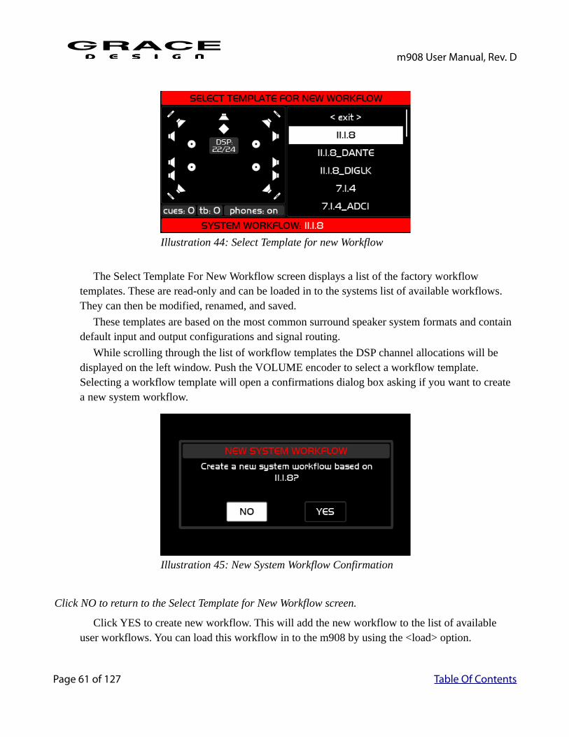
m908 User Manual, Rev. D
The Select Template For New Workflow screen displays a list of the factory workflow templates. These are read-only and can be loaded in to the systems list of available workflows. They can then be modified, renamed, and saved.
These templates are based on the most common surround speaker system formats and contain default input and output configurations and signal routing.
While scrolling through the list of workflow templates the DSP channel allocations will be displayed on the left window. Push the VOLUME encoder to select a workflow template. Selecting a workflow template will open a confirmations dialog box asking if you want to create a new system workflow.
Click NO to return to the Select Template for New Workflow screen.
Click YES to create new workflow. This will add the new workflow to the list of available user workflows. You can load this workflow in to the m908 by using the <load> option.
Page 61 of 127 Table Of Contents
Illustration 44: Select Template for new Workflow
Illustration 45: New System Workflow Confirmation
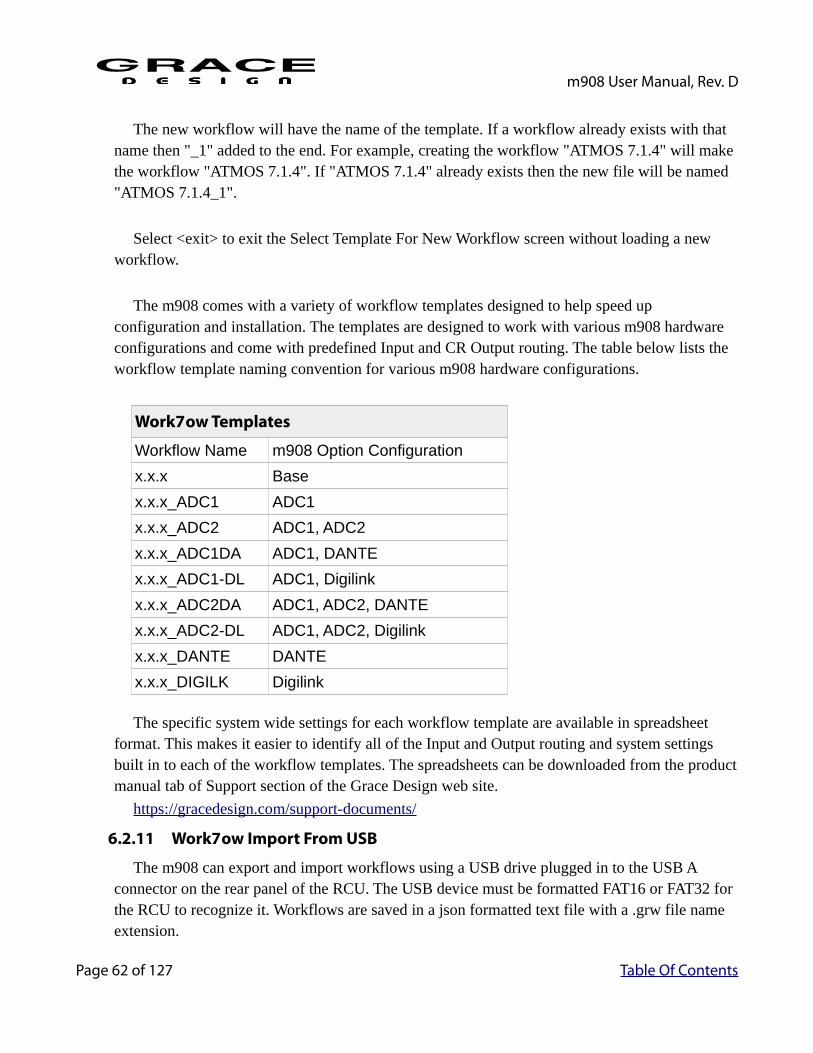
m908 User Manual, Rev. D
The new workflow will have the name of the template. If a workflow already exists with that name then "_1" added to the end. For example, creating the workflow "ATMOS 7.1.4" will make the workflow "ATMOS 7.1.4". If "ATMOS 7.1.4" already exists then the new file will be named "ATMOS 7.1.4_1".
Select <exit> to exit the Select Template For New Workflow screen without loading a new workflow.
The m908 comes with a variety of workflow templates designed to help speed up configuration and installation. The templates are designed to work with various m908 hardware configurations and come with predefined Input and CR Output routing. The table below lists the workflow template naming convention for various m908 hardware configurations.
Workfow Templates
Workflow Name m908 Option Configuration
x.x.x Base
x.x.x_ADC1 ADC1
x.x.x_ADC2 ADC1, ADC2
x.x.x_ADC1DA ADC1, DANTE
x.x.x_ADC1-DL ADC1, Digilink
x.x.x_ADC2DA ADC1, ADC2, DANTE
x.x.x_ADC2-DL ADC1, ADC2, Digilink
x.x.x_DANTE DANTE
x.x.x_DIGILK Digilink
The specific system wide settings for each workflow template are available in spreadsheet format. This makes it easier to identify all of the Input and Output routing and system settings built in to each of the workflow templates. The spreadsheets can be downloaded from the productmanual tab of Support section of the Grace Design web site.
https://gracedesign.com/support-documents/
6.2.11 Workfow Import From USm
The m908 can export and import workflows using a USB drive plugged in to the USB A connector on the rear panel of the RCU. The USB device must be formatted FAT16 or FAT32 for the RCU to recognize it. Workflows are saved in a json formatted text file with a .grw file name extension.
Page 62 of 127 Table Of Contents
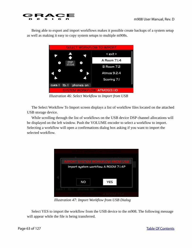
m908 User Manual, Rev. D
Being able to export and import workflows makes it possible create backups of a system setupas well as making it easy to copy system setups to multiple m908s.
The Select Workflow To Import screen displays a list of workflow files located on the attachedUSB storage device.
While scrolling through the list of workflows on the USB device DSP channel allocations willbe displayed on the left window. Push the VOLUME encoder to select a workflow to import. Selecting a workflow will open a confirmations dialog box asking if you want to import the selected workflow.
Select YES to import the workflow from the USB device to the m908. The following message will appear while the file is being transferred.
Page 63 of 127 Table Of Contents
Illustration 46: Select Workflow to Import from USB
Illustration 47: Import Workflow from USB Dialog
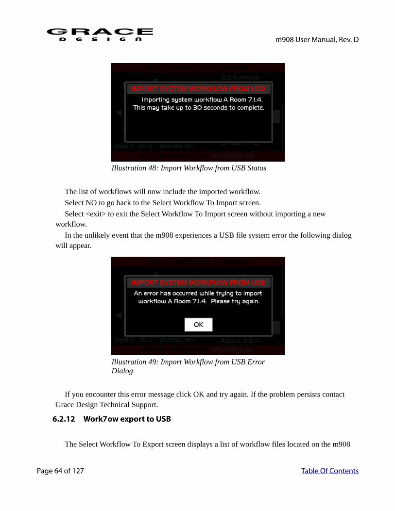
m908 User Manual, Rev. D
The list of workflows will now include the imported workflow.
Select NO to go back to the Select Workflow To Import screen.
Select <exit> to exit the Select Workflow To Import screen without importing a new workflow.
In the unlikely event that the m908 experiences a USB file system error the following dialog will appear.
If you encounter this error message click OK and try again. If the problem persists contact Grace Design Technical Support.
6.2.12 Workfow export to USm
The Select Workflow To Export screen displays a list of workflow files located on the m908
Page 64 of 127 Table Of Contents
Illustration 49: Import Workflow from USB Error Dialog
Illustration 48: Import Workflow from USB Status
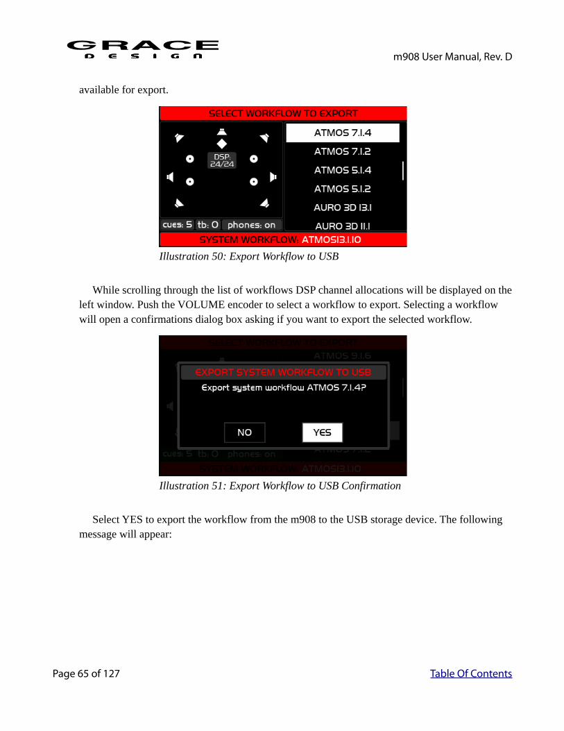
m908 User Manual, Rev. D
available for export.
While scrolling through the list of workflows DSP channel allocations will be displayed on theleft window. Push the VOLUME encoder to select a workflow to export. Selecting a workflow will open a confirmations dialog box asking if you want to export the selected workflow.
Select YES to export the workflow from the m908 to the USB storage device. The following message will appear:
Page 65 of 127 Table Of Contents
Illustration 51: Export Workflow to USB Confirmation
Illustration 50: Export Workflow to USB
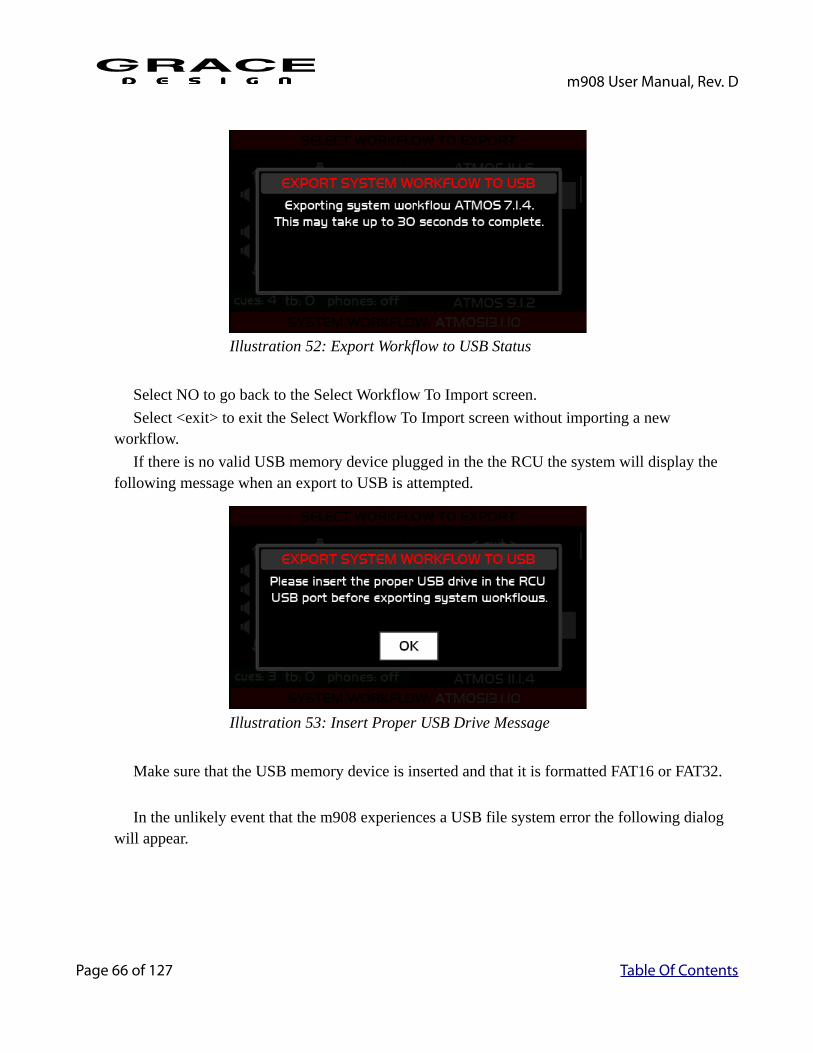
m908 User Manual, Rev. D
Select NO to go back to the Select Workflow To Import screen.
Select <exit> to exit the Select Workflow To Import screen without importing a new workflow.
If there is no valid USB memory device plugged in the the RCU the system will display the following message when an export to USB is attempted.
Make sure that the USB memory device is inserted and that it is formatted FAT16 or FAT32.
In the unlikely event that the m908 experiences a USB file system error the following dialog will appear.
Page 66 of 127 Table Of Contents
Illustration 53: Insert Proper USB Drive Message
Illustration 52: Export Workflow to USB Status
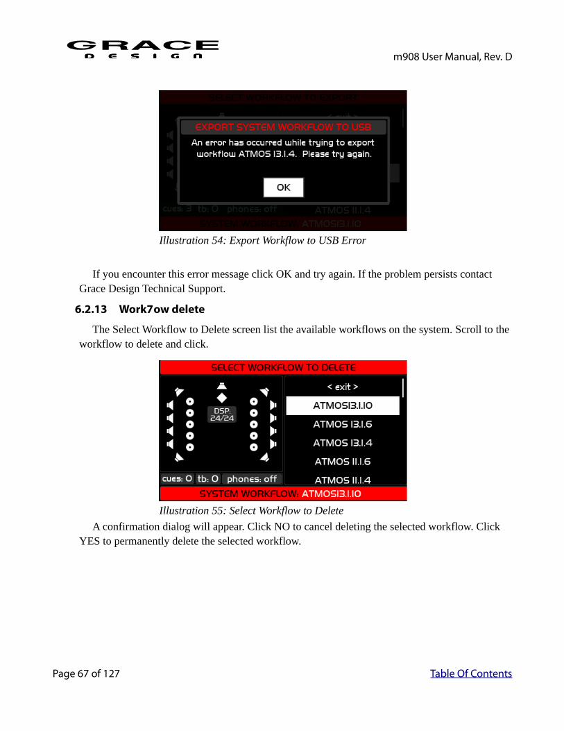
m908 User Manual, Rev. D
If you encounter this error message click OK and try again. If the problem persists contact Grace Design Technical Support.
6.2.13 Workfow delete
The Select Workflow to Delete screen list the available workflows on the system. Scroll to theworkflow to delete and click.
A confirmation dialog will appear. Click NO to cancel deleting the selected workflow. Click YES to permanently delete the selected workflow.
Page 67 of 127 Table Of Contents
Illustration 55: Select Workflow to Delete
Illustration 54: Export Workflow to USB Error
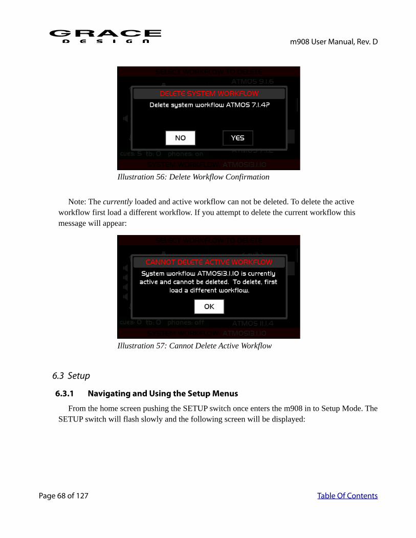
m908 User Manual, Rev. D
Note: The currently loaded and active workflow can not be deleted. To delete the active workflow first load a different workflow. If you attempt to delete the current workflow this message will appear:
6.3 Setup
6.3.1 Navigating and Using the Setup Menus
From the home screen pushing the SETUP switch once enters the m908 in to Setup Mode. TheSETUP switch will flash slowly and the following screen will be displayed:
Page 68 of 127 Table Of Contents
Illustration 57: Cannot Delete Active Workflow
Illustration 56: Delete Workflow Confirmation
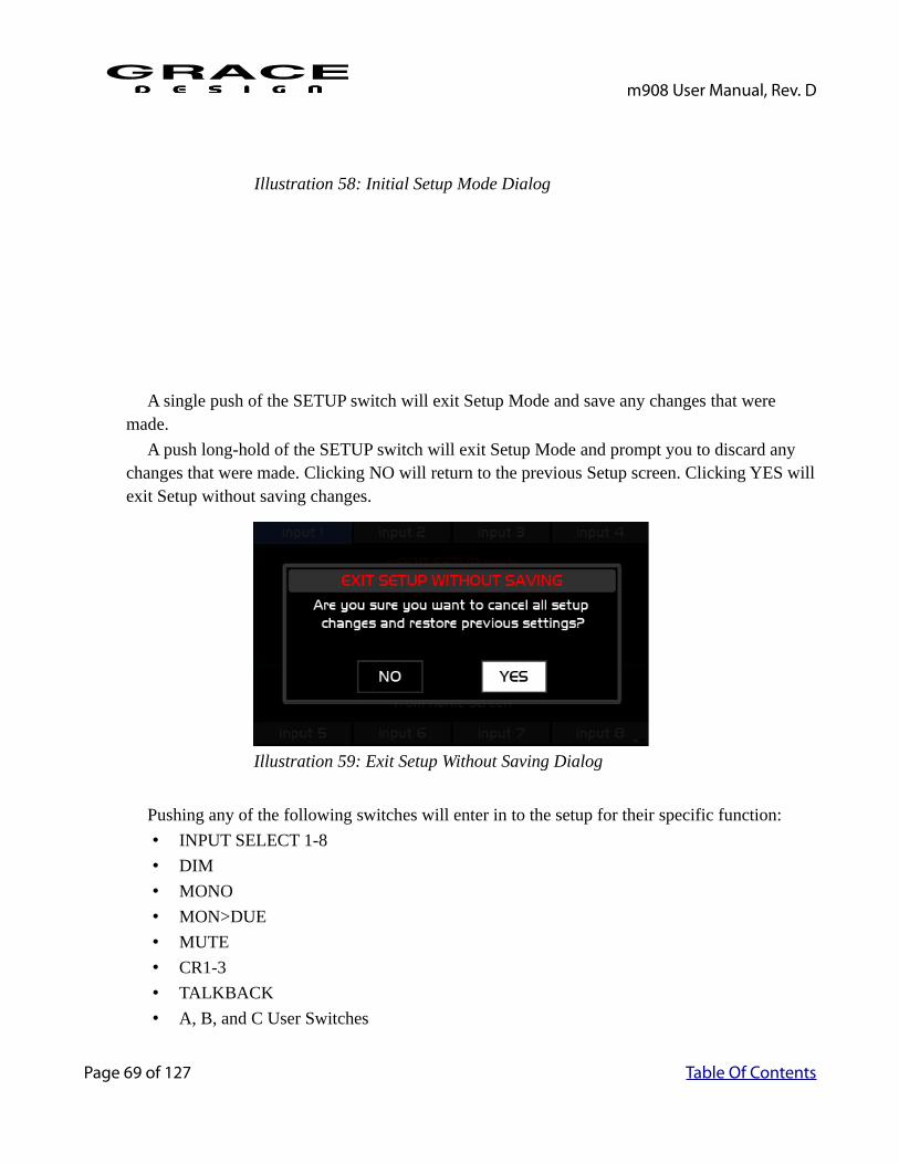
m908 User Manual, Rev. D
A single push of the SETUP switch will exit Setup Mode and save any changes that were made.
A push long-hold of the SETUP switch will exit Setup Mode and prompt you to discard any changes that were made. Clicking NO will return to the previous Setup screen. Clicking YES willexit Setup without saving changes.
Pushing any of the following switches will enter in to the setup for their specific function:
• INPUT SELECT 1-8
• DIM
• MONO
• MON>DUE
• MUTE
• CR1-3
• TALKBACK
• A, B, and C User Switches
Page 69 of 127 Table Of Contents
Illustration 58: Initial Setup Mode Dialog
Illustration 59: Exit Setup Without Saving Dialog
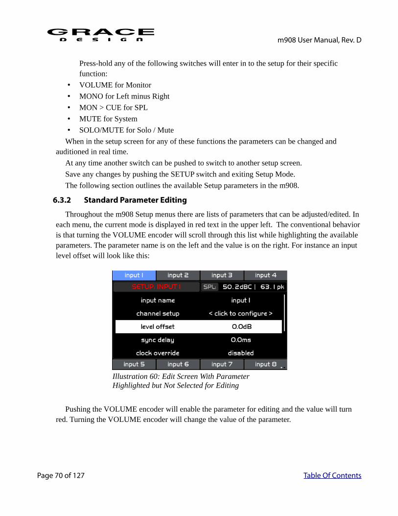
m908 User Manual, Rev. D
Press-hold any of the following switches will enter in to the setup for their specific function:
• VOLUME for Monitor
• MONO for Left minus Right
• MON > CUE for SPL
• MUTE for System
• SOLO/MUTE for Solo / Mute
When in the setup screen for any of these functions the parameters can be changed and auditioned in real time.
At any time another switch can be pushed to switch to another setup screen.
Save any changes by pushing the SETUP switch and exiting Setup Mode.
The following section outlines the available Setup parameters in the m908.
6.3.2 Standard Parameter Editing
Throughout the m908 Setup menus there are lists of parameters that can be adjusted/edited. In each menu, the current mode is displayed in red text in the upper left. The conventional behavioris that turning the VOLUME encoder will scroll through this list while highlighting the available parameters. The parameter name is on the left and the value is on the right. For instance an input level offset will look like this:
Pushing the VOLUME encoder will enable the parameter for editing and the value will turn red. Turning the VOLUME encoder will change the value of the parameter.
Page 70 of 127 Table Of Contents
Illustration 60: Edit Screen With Parameter Highlighted but Not Selected for Editing
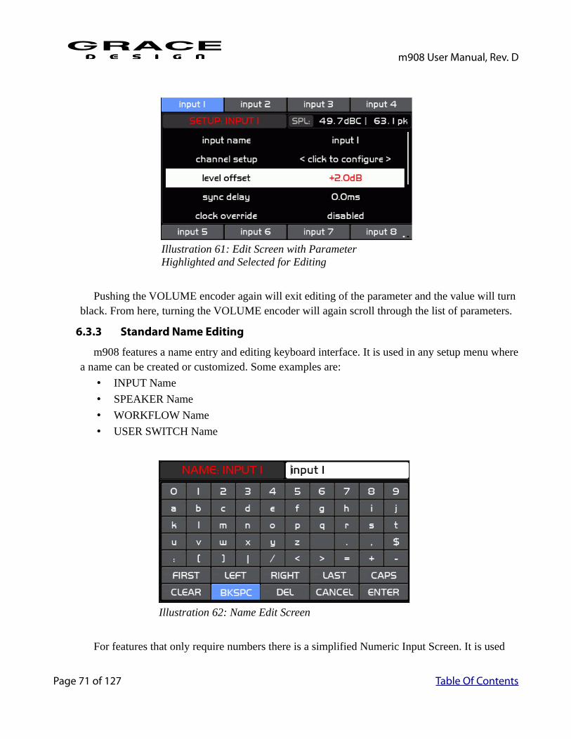
m908 User Manual, Rev. D
Pushing the VOLUME encoder again will exit editing of the parameter and the value will turn black. From here, turning the VOLUME encoder will again scroll through the list of parameters.
6.3.3 Standard Name Editing
m908 features a name entry and editing keyboard interface. It is used in any setup menu wherea name can be created or customized. Some examples are:
• INPUT Name
• SPEAKER Name
• WORKFLOW Name
• USER SWITCH Name
For features that only require numbers there is a simplified Numeric Input Screen. It is used
Page 71 of 127 Table Of Contents
Illustration 61: Edit Screen with Parameter Highlighted and Selected for Editing
Illustration 62: Name Edit Screen
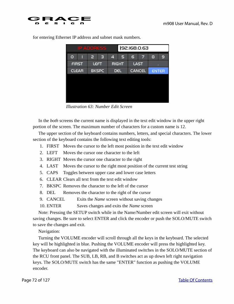
m908 User Manual, Rev. D
for entering Ethernet IP address and subnet mask numbers.
In the both screens the current name is displayed in the text edit window in the upper right portion of the screen. The maximum number of characters for a custom name is 12.
The upper section of the keyboard contains numbers, letters, and special characters. The lowersection of the keyboard contains the following text editing tools:
1. FIRST Moves the cursor to the left most position in the text edit window
2. LEFT Moves the cursor one character to the left
3. RIGHT Moves the cursor one character to the right
4. LAST Moves the cursor to the right most position of the current test string
5. CAPS Toggles between upper case and lower case letters
6. CLEAR Clears all text from the text edit window
7. BKSPC Removes the character to the left of the cursor
8. DEL Removes the character to the right of the cursor
9. CANCEL Exits the Name screen without saving changes
10. ENTER Saves changes and exits the Name screen
Note: Pressing the SETUP switch while in the Name/Number edit screen will exit without saving changes. Be sure to select ENTER and click the encoder or push the SOLO/MUTE switchto save the changes and exit.
Navigation:
Turning the VOLUME encoder will scroll through all the keys in the keyboard. The selected key will be highlighted in blue. Pushing the VOLUME encoder will press the highlighted key. The keyboard can also be navigated with the illuminated switches in the SOLO/MUTE section ofthe RCU front panel. The SUB, LB, RB, and B switches act as up down left right navigation keys. The SOLO/MUTE switch has the same "ENTER" function as pushing the VOLUME encoder.
Page 72 of 127 Table Of Contents
Illustration 63: Number Edit Screen
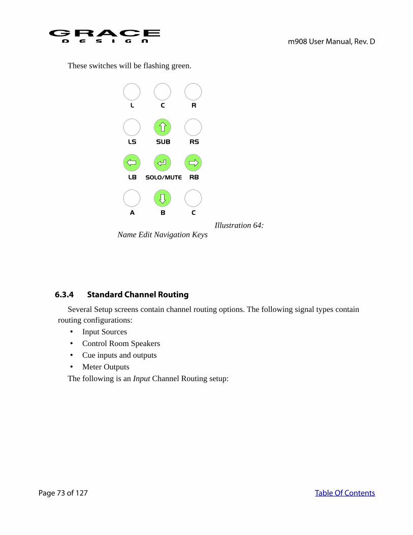
m908 User Manual, Rev. D
These switches will be flashing green.
6.3.4 Standard Channel Routing
Several Setup screens contain channel routing options. The following signal types contain routing configurations:
• Input Sources
• Control Room Speakers
• Cue inputs and outputs
• Meter Outputs
The following is an Input Channel Routing setup:
Page 73 of 127 Table Of Contents
L C R
RSLS SUB
RBSOLO/MUTE
A
LB
B C
Illustration 64:Name Edit Navigation Keys
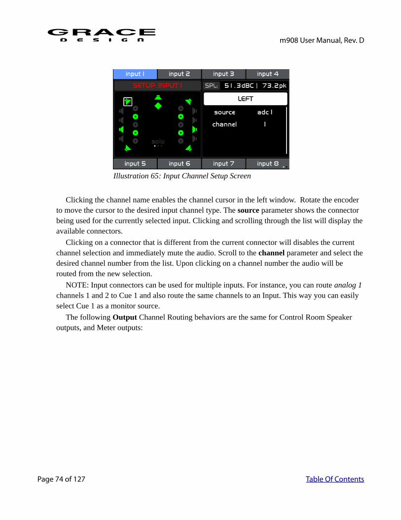
m908 User Manual, Rev. D
Clicking the channel name enables the channel cursor in the left window. Rotate the encoder to move the cursor to the desired input channel type. The source parameter shows the connector being used for the currently selected input. Clicking and scrolling through the list will display theavailable connectors.
Clicking on a connector that is different from the current connector will disables the current channel selection and immediately mute the audio. Scroll to the channel parameter and select thedesired channel number from the list. Upon clicking on a channel number the audio will be routed from the new selection.
NOTE: Input connectors can be used for multiple inputs. For instance, you can route analog 1 channels 1 and 2 to Cue 1 and also route the same channels to an Input. This way you can easily select Cue 1 as a monitor source.
The following Output Channel Routing behaviors are the same for Control Room Speaker outputs, and Meter outputs:
Page 74 of 127 Table Of Contents
Illustration 65: Input Channel Setup Screen
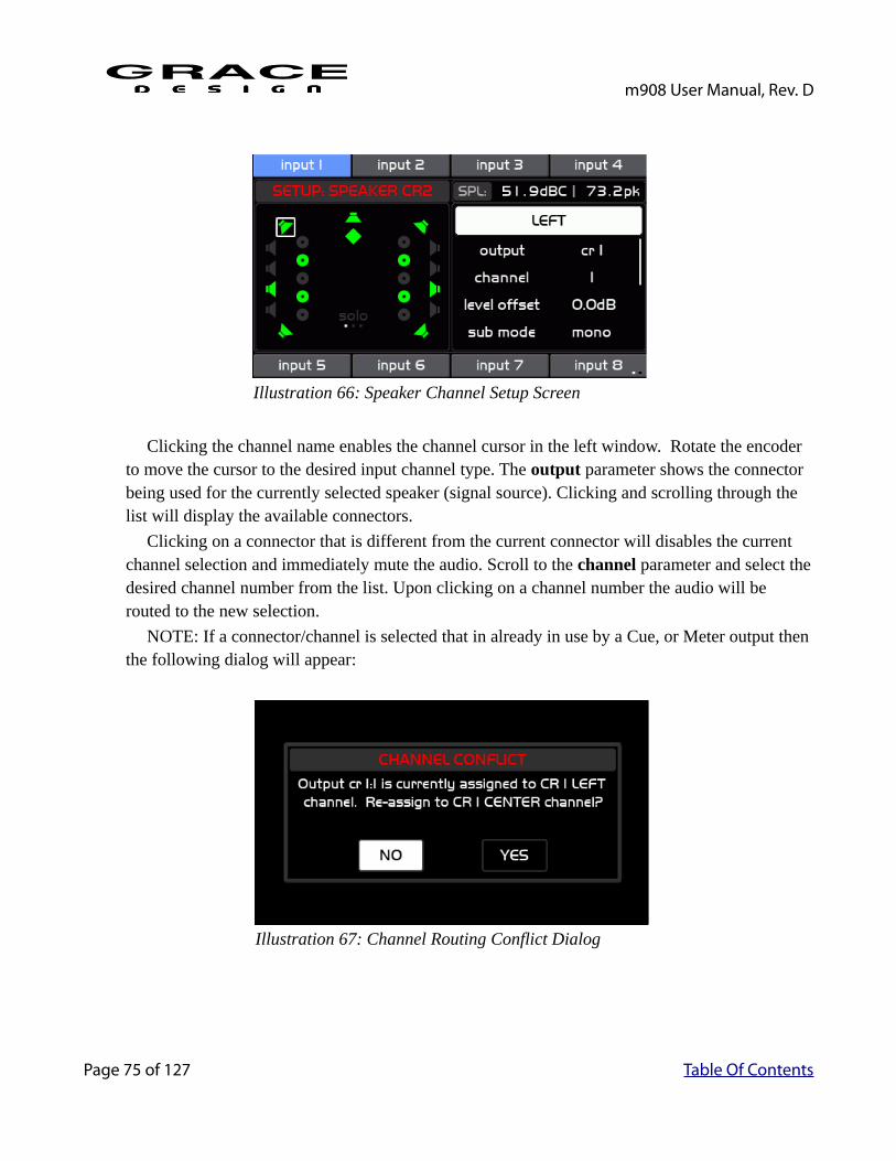
m908 User Manual, Rev. D
Clicking the channel name enables the channel cursor in the left window. Rotate the encoder to move the cursor to the desired input channel type. The output parameter shows the connector being used for the currently selected speaker (signal source). Clicking and scrolling through the list will display the available connectors.
Clicking on a connector that is different from the current connector will disables the current channel selection and immediately mute the audio. Scroll to the channel parameter and select thedesired channel number from the list. Upon clicking on a channel number the audio will be routed to the new selection.
NOTE: If a connector/channel is selected that in already in use by a Cue, or Meter output then the following dialog will appear:
Page 75 of 127 Table Of Contents
Illustration 66: Speaker Channel Setup Screen
Illustration 67: Channel Routing Conflict Dialog
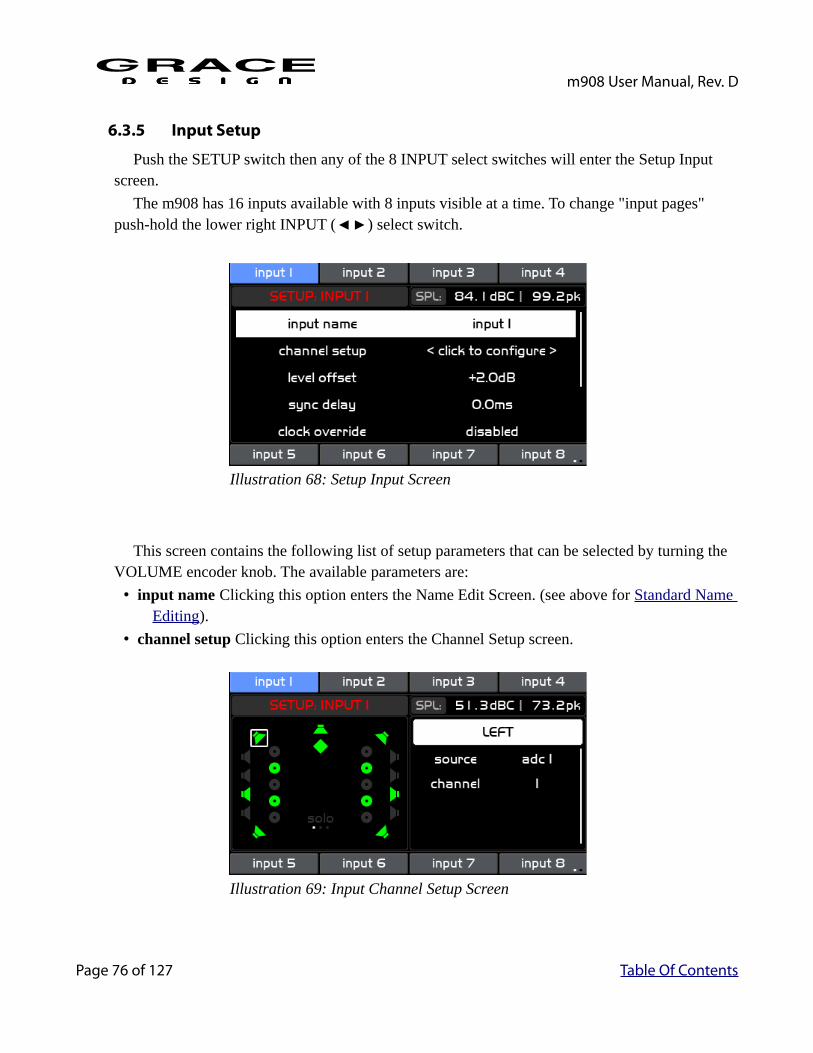
m908 User Manual, Rev. D
6.3.5 Input Setup
Push the SETUP switch then any of the 8 INPUT select switches will enter the Setup Input screen.
The m908 has 16 inputs available with 8 inputs visible at a time. To change "input pages" push-hold the lower right INPUT () select switch.
This screen contains the following list of setup parameters that can be selected by turning the VOLUME encoder knob. The available parameters are:
• input name Clicking this option enters the Name Edit Screen. (see above for Standard Name Editing).
• channel setup Clicking this option enters the Channel Setup screen.
Page 76 of 127 Table Of Contents
Illustration 68: Setup Input Screen
Illustration 69: Input Channel Setup Screen
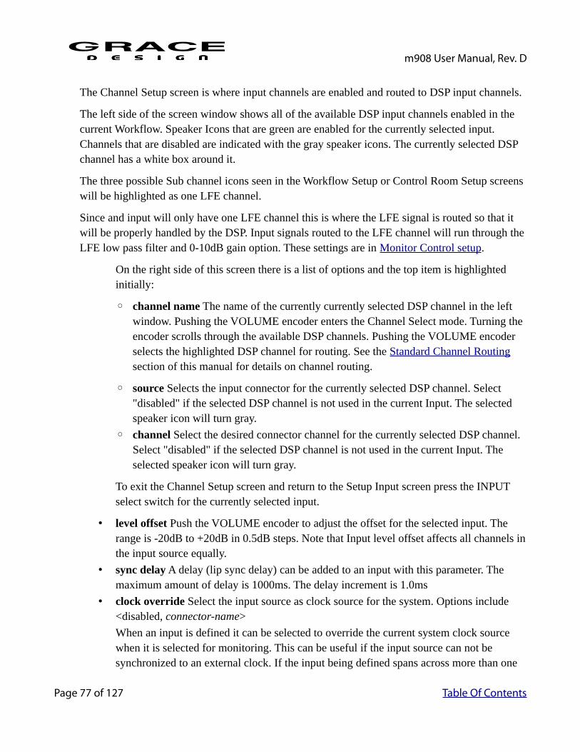
m908 User Manual, Rev. D
The Channel Setup screen is where input channels are enabled and routed to DSP input channels.
The left side of the screen window shows all of the available DSP input channels enabled in the current Workflow. Speaker Icons that are green are enabled for the currently selected input. Channels that are disabled are indicated with the gray speaker icons. The currently selected DSP channel has a white box around it.
The three possible Sub channel icons seen in the Workflow Setup or Control Room Setup screens will be highlighted as one LFE channel.
Since and input will only have one LFE channel this is where the LFE signal is routed so that it will be properly handled by the DSP. Input signals routed to the LFE channel will run through theLFE low pass filter and 0-10dB gain option. These settings are in Monitor Control setup.
On the right side of this screen there is a list of options and the top item is highlighted initially:
channel name The name of the currently currently selected DSP channel in the left window. Pushing the VOLUME encoder enters the Channel Select mode. Turning the encoder scrolls through the available DSP channels. Pushing the VOLUME encoder selects the highlighted DSP channel for routing. See the Standard Channel Routing section of this manual for details on channel routing.
source Selects the input connector for the currently selected DSP channel. Select "disabled" if the selected DSP channel is not used in the current Input. The selected speaker icon will turn gray.
channel Select the desired connector channel for the currently selected DSP channel. Select "disabled" if the selected DSP channel is not used in the current Input. The selected speaker icon will turn gray.
To exit the Channel Setup screen and return to the Setup Input screen press the INPUT select switch for the currently selected input.
• level offset Push the VOLUME encoder to adjust the offset for the selected input. The range is -20dB to +20dB in 0.5dB steps. Note that Input level offset affects all channels inthe input source equally.
• sync delay A delay (lip sync delay) can be added to an input with this parameter. The maximum amount of delay is 1000ms. The delay increment is 1.0ms
• clock override Select the input source as clock source for the system. Options include <disabled, connector-name>
When an input is defined it can be selected to override the current system clock source when it is selected for monitoring. This can be useful if the input source can not be synchronized to an external clock. If the input being defined spans across more than one
Page 77 of 127 Table Of Contents
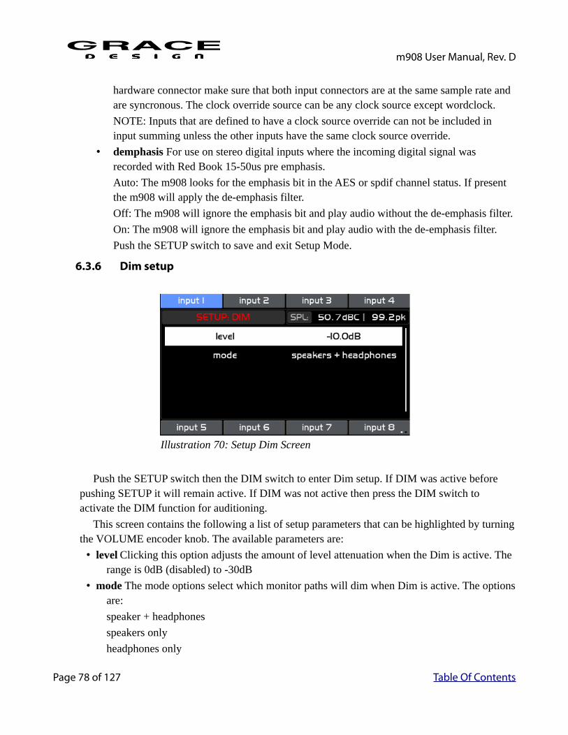
m908 User Manual, Rev. D
hardware connector make sure that both input connectors are at the same sample rate and are syncronous. The clock override source can be any clock source except wordclock.
NOTE: Inputs that are defined to have a clock source override can not be included in input summing unless the other inputs have the same clock source override.
• demphasis For use on stereo digital inputs where the incoming digital signal was recorded with Red Book 15-50us pre emphasis.
Auto: The m908 looks for the emphasis bit in the AES or spdif channel status. If present the m908 will apply the de-emphasis filter.
Off: The m908 will ignore the emphasis bit and play audio without the de-emphasis filter.
On: The m908 will ignore the emphasis bit and play audio with the de-emphasis filter.
Push the SETUP switch to save and exit Setup Mode.
6.3.6 Dim setup
Push the SETUP switch then the DIM switch to enter Dim setup. If DIM was active before pushing SETUP it will remain active. If DIM was not active then press the DIM switch to activate the DIM function for auditioning.
This screen contains the following a list of setup parameters that can be highlighted by turningthe VOLUME encoder knob. The available parameters are:
• level Clicking this option adjusts the amount of level attenuation when the Dim is active. The range is 0dB (disabled) to -30dB
• mode The mode options select which monitor paths will dim when Dim is active. The optionsare:
speaker + headphones
speakers only
headphones only
Page 78 of 127 Table Of Contents
Illustration 70: Setup Dim Screen
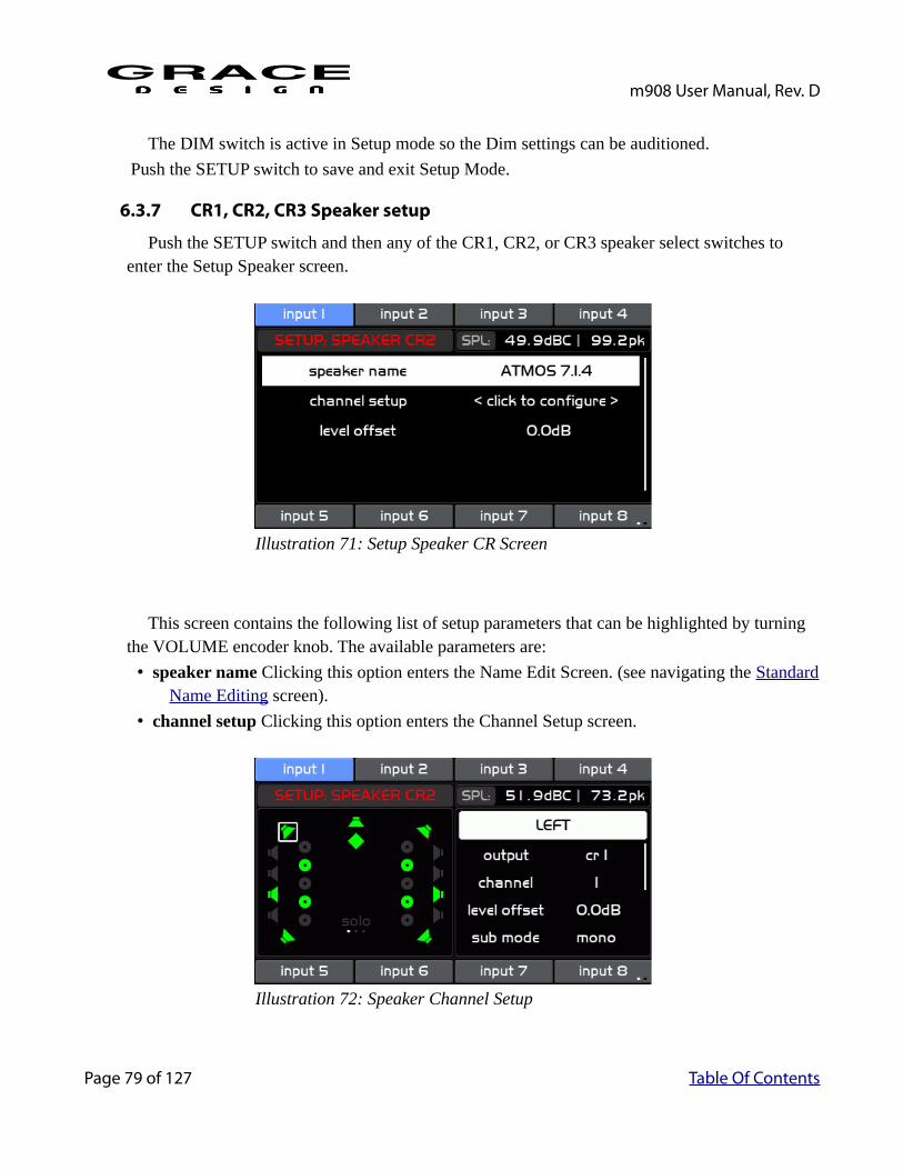
m908 User Manual, Rev. D
The DIM switch is active in Setup mode so the Dim settings can be auditioned.
Push the SETUP switch to save and exit Setup Mode.
6.3.7 CR1, CR2, CR3 Speaker setup
Push the SETUP switch and then any of the CR1, CR2, or CR3 speaker select switches to enter the Setup Speaker screen.
This screen contains the following list of setup parameters that can be highlighted by turning the VOLUME encoder knob. The available parameters are:
• speaker name Clicking this option enters the Name Edit Screen. (see navigating the StandardName Editing screen).
• channel setup Clicking this option enters the Channel Setup screen.
Page 79 of 127 Table Of Contents
Illustration 71: Setup Speaker CR Screen
Illustration 72: Speaker Channel Setup
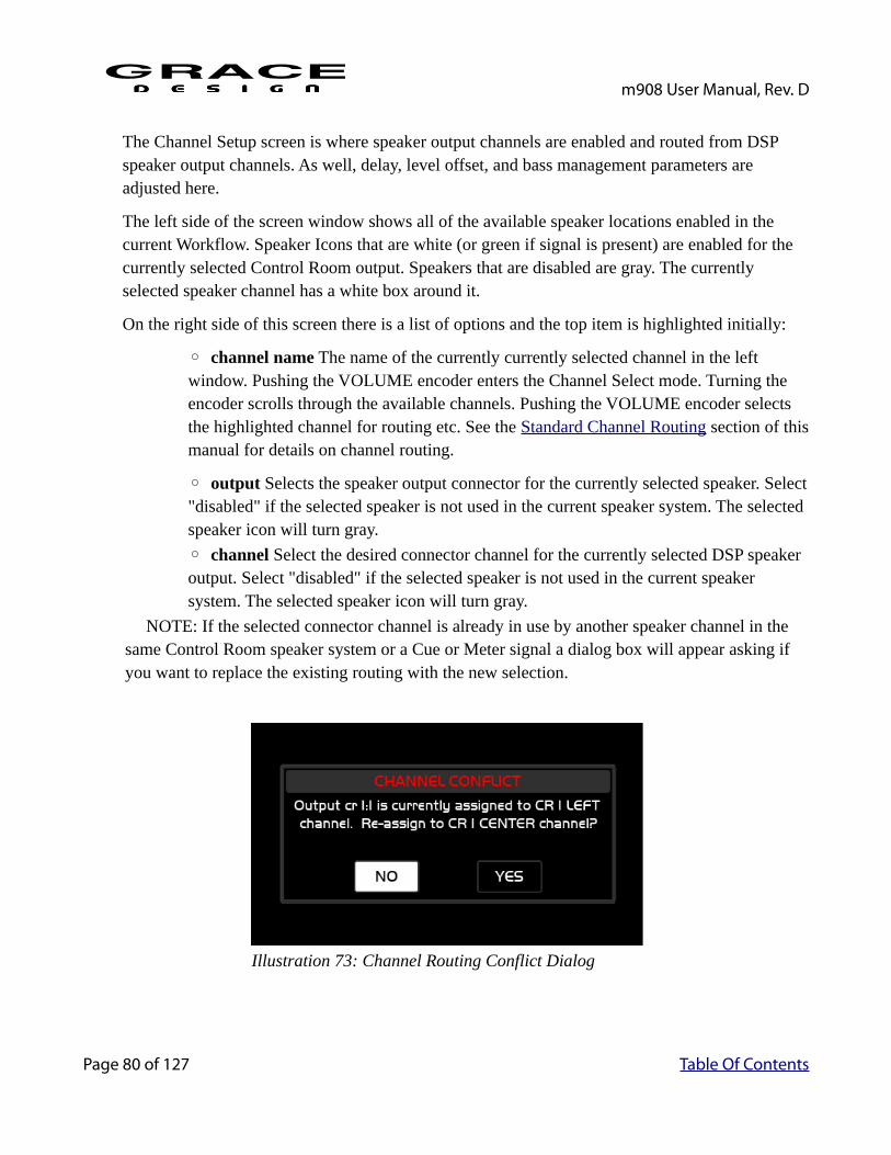
m908 User Manual, Rev. D
The Channel Setup screen is where speaker output channels are enabled and routed from DSP speaker output channels. As well, delay, level offset, and bass management parameters are adjusted here.
The left side of the screen window shows all of the available speaker locations enabled in the current Workflow. Speaker Icons that are white (or green if signal is present) are enabled for the currently selected Control Room output. Speakers that are disabled are gray. The currently selected speaker channel has a white box around it.
On the right side of this screen there is a list of options and the top item is highlighted initially:
channel name The name of the currently currently selected channel in the left window. Pushing the VOLUME encoder enters the Channel Select mode. Turning the encoder scrolls through the available channels. Pushing the VOLUME encoder selects the highlighted channel for routing etc. See the Standard Channel Routing section of thismanual for details on channel routing.
output Selects the speaker output connector for the currently selected speaker. Select"disabled" if the selected speaker is not used in the current speaker system. The selected speaker icon will turn gray.
channel Select the desired connector channel for the currently selected DSP speaker output. Select "disabled" if the selected speaker is not used in the current speaker system. The selected speaker icon will turn gray.
NOTE: If the selected connector channel is already in use by another speaker channel in the same Control Room speaker system or a Cue or Meter signal a dialog box will appear asking if you want to replace the existing routing with the new selection.
Page 80 of 127 Table Of Contents
Illustration 73: Channel Routing Conflict Dialog
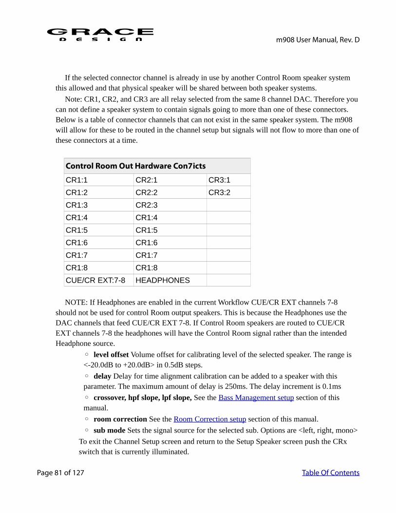
m908 User Manual, Rev. D
If the selected connector channel is already in use by another Control Room speaker system this allowed and that physical speaker will be shared between both speaker systems.
Note: CR1, CR2, and CR3 are all relay selected from the same 8 channel DAC. Therefore youcan not define a speaker system to contain signals going to more than one of these connectors. Below is a table of connector channels that can not exist in the same speaker system. The m908 will allow for these to be routed in the channel setup but signals will not flow to more than one ofthese connectors at a time.
Control Room Out Hardware Conficts
CR1:1 CR2:1 CR3:1
CR1:2 CR2:2 CR3:2
CR1:3 CR2:3
CR1:4 CR1:4
CR1:5 CR1:5
CR1:6 CR1:6
CR1:7 CR1:7
CR1:8 CR1:8
CUE/CR EXT:7-8 HEADPHONES
NOTE: If Headphones are enabled in the current Workflow CUE/CR EXT channels 7-8 should not be used for control Room output speakers. This is because the Headphones use the DAC channels that feed CUE/CR EXT 7-8. If Control Room speakers are routed to CUE/CR EXT channels 7-8 the headphones will have the Control Room signal rather than the intended Headphone source.
level offset Volume offset for calibrating level of the selected speaker. The range is <-20.0dB to +20.0dB> in 0.5dB steps.
delay Delay for time alignment calibration can be added to a speaker with this parameter. The maximum amount of delay is 250ms. The delay increment is 0.1ms
crossover, hpf slope, lpf slope, See the Bass Management setup section of this manual.
room correction See the Room Correction setup section of this manual.
sub mode Sets the signal source for the selected sub. Options are <left, right, mono>
To exit the Channel Setup screen and return to the Setup Speaker screen push the CRx switch that is currently illuminated.
Page 81 of 127 Table Of Contents
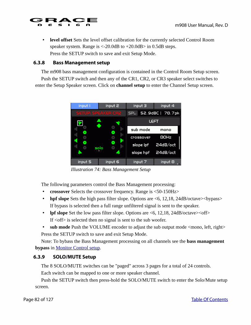
m908 User Manual, Rev. D
• level offset Sets the level offset calibration for the currently selected Control Room speaker system. Range is <-20.0dB to +20.0dB> in 0.5dB steps.
Press the SETUP switch to save and exit Setup Mode.
6.3.8 mass Management setup
The m908 bass management configuration is contained in the Control Room Setup screen.
Push the SETUP switch and then any of the CR1, CR2, or CR3 speaker select switches to enter the Setup Speaker screen. Click on channel setup to enter the Channel Setup screen.
The following parameters control the Bass Management processing:
• crossover Selects the crossover frequency. Range is <50-150Hz>
• hpf slope Sets the high pass filter slope. Options are <6, 12,18, 24dB/octave><bypass>
If bypass is selected then a full range unfiltered signal is sent to the speaker.
• lpf slope Set the low pass filter slope. Options are <6, 12,18, 24dB/octave><off>
If <off> is selected then no signal is sent to the sub woofer.
• sub mode Push the VOLUME encoder to adjust the sub output mode <mono, left, right>
Press the SETUP switch to save and exit Setup Mode.
Note: To bybass the Bass Management processing on all channels see the bass management bypass in Monitor Control setup.
6.3.9 SOLO/MUTE Setup
The 8 SOLO/MUTE switches can be "paged" across 3 pages for a total of 24 controls.
Each switch can be mapped to one or more speaker channel.
Push the SETUP switch then press-hold the SOLO/MUTE switch to enter the Solo/Mute setupscreen.
Page 82 of 127 Table Of Contents
Illustration 74: Bass Management Setup
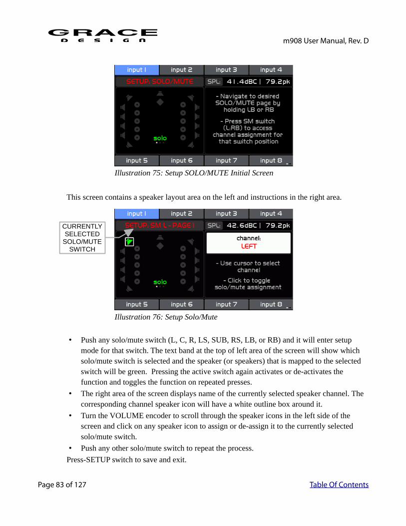
m908 User Manual, Rev. D
This screen contains a speaker layout area on the left and instructions in the right area.
• Push any solo/mute switch (L, C, R, LS, SUB, RS, LB, or RB) and it will enter setup mode for that switch. The text band at the top of left area of the screen will show which solo/mute switch is selected and the speaker (or speakers) that is mapped to the selected switch will be green. Pressing the active switch again activates or de-activates the function and toggles the function on repeated presses.
• The right area of the screen displays name of the currently selected speaker channel. The corresponding channel speaker icon will have a white outline box around it.
• Turn the VOLUME encoder to scroll through the speaker icons in the left side of the screen and click on any speaker icon to assign or de-assign it to the currently selected solo/mute switch.
• Push any other solo/mute switch to repeat the process.
Press-SETUP switch to save and exit.
Page 83 of 127 Table Of Contents
Illustration 75: Setup SOLO/MUTE Initial Screen
Illustration 76: Setup Solo/Mute
CURRENTLYSELECTED
SOLO/MUTE SWITCH
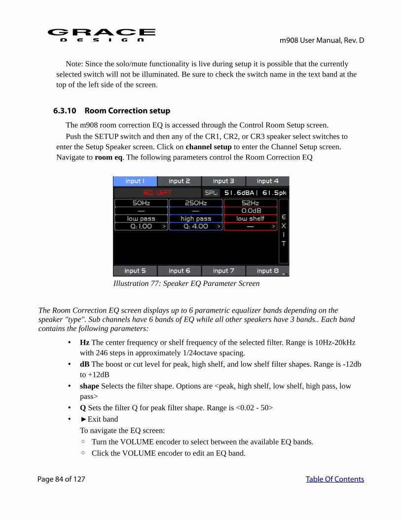
m908 User Manual, Rev. D
Note: Since the solo/mute functionality is live during setup it is possible that the currently selected switch will not be illuminated. Be sure to check the switch name in the text band at the top of the left side of the screen.
6.3.10 Room Correction setup
The m908 room correction EQ is accessed through the Control Room Setup screen.
Push the SETUP switch and then any of the CR1, CR2, or CR3 speaker select switches to enter the Setup Speaker screen. Click on channel setup to enter the Channel Setup screen. Navigate to room eq. The following parameters control the Room Correction EQ
The Room Correction EQ screen displays up to 6 parametric equalizer bands depending on the speaker "type". Sub channels have 6 bands of EQ while all other speakers have 3 bands.. Each band contains the following parameters:
• Hz The center frequency or shelf frequency of the selected filter. Range is 10Hz-20kHz with 246 steps in approximately 1/24octave spacing.
• dB The boost or cut level for peak, high shelf, and low shelf filter shapes. Range is -12db to +12dB
• shape Selects the filter shape. Options are <peak, high shelf, low shelf, high pass, low pass>
• Q Sets the filter Q for peak filter shape. Range is <0.02 - 50>
• Exit band
To navigate the EQ screen:
Turn the VOLUME encoder to select between the available EQ bands.
Click the VOLUME encoder to edit an EQ band.
Page 84 of 127 Table Of Contents
Illustration 77: Speaker EQ Parameter Screen
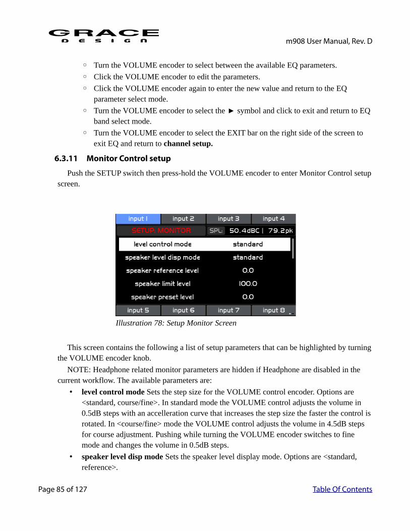
m908 User Manual, Rev. D
Turn the VOLUME encoder to select between the available EQ parameters.
Click the VOLUME encoder to edit the parameters.
Click the VOLUME encoder again to enter the new value and return to the EQ parameter select mode.
Turn the VOLUME encoder to select the symbol and click to exit and return to EQband select mode.
Turn the VOLUME encoder to select the EXIT bar on the right side of the screen to exit EQ and return to channel setup.
6.3.11 Monitor Control setup
Push the SETUP switch then press-hold the VOLUME encoder to enter Monitor Control setupscreen.
This screen contains the following a list of setup parameters that can be highlighted by turningthe VOLUME encoder knob.
NOTE: Headphone related monitor parameters are hidden if Headphone are disabled in the current workflow. The available parameters are:
• level control mode Sets the step size for the VOLUME control encoder. Options are <standard, course/fine>. In standard mode the VOLUME control adjusts the volume in 0.5dB steps with an accelleration curve that increases the step size the faster the control isrotated. In <course/fine> mode the VOLUME control adjusts the volume in 4.5dB steps for course adjustment. Pushing while turning the VOLUME encoder switches to fine mode and changes the volume in 0.5dB steps.
• speaker level disp mode Sets the speaker level display mode. Options are <standard, reference>.
Page 85 of 127 Table Of Contents
Illustration 78: Setup Monitor Screen
m908 User Manual, Rev. D
• speaker reference level Adjusts the speaker reference level. Range is <0 to 100> in 0.5dB steps. This parameter represents the reference level that is displayed (when speaker level display mode = reference level) at the current volume setting. Available range is the current volume setting +/- 100 in 0.5 steps. This parameter is the same for all speaker outputs.
The following is an example of how the reference level may be configured for an 82dBSPL reference listening level:
Play and monitor a nominal level noise source.
Adjust the speaker level until the SPL measurement at the listening position equals 82dBSPL.
Enter SETUP then push-hold the VOLUME encoder to enter the Setup Monitor screen and navigate to speaker reference level parameter. Adjust it to 82.
Set speaker level disp mode to <reference>
• speaker limit level Sets the maximum volume level that the Control Room speaker can be set to.
• speaker preset level Sets the level that the speaker system will go when on push-hold of the VOLUME encoder while in the Home screen.
• speaker power-up level Sets the volume level that the speaker system will go to after power up.
• lfe input lpf freq Enables and sets the LFE channel low pass filter cutoff frequency. Options are <bypass, 80-120hZ>
• lfe input gain Sets the LFE channel gain. Options are <0db, +10dB>
• bass management Enables or disables bass management. Options are: <bypassed, enabled>
• room equalization Enables or disables all room correction equalizers. Options are: <bypassed, enabled>
• headphone source Selects the stereo signal source for the headphone amplifier. Options are <left/right, downmix, cue 1-8>.
left/right: the headphone source is the same signal feeding Control Room left and right with mono,l-r and mute behavior as configured in setup menus. If downmix is active in the CR Outputs the headphones will receive the downmixed signal.
downmix: Inserts the stereo output phones/cue downmixer for monitoring in stereo when the CR Outputs are monitoring in surround.
cue 1-8: Routes one of the Cue outputs to the headphone amplifier. When a cue is being monitored on headphones the Cue output routing is still active.
• headphone gain Adjusts the gain of the headphone system to match the sensitivity of your headphones. Adjustment range is -20dB to +20dB in 0.5dB steps.
Page 86 of 127 Table Of Contents
m908 User Manual, Rev. D
• headphone balance Adjusts the Left-Right balance of the headphones. Depending on the direction the VOLUME encoder is turned the Left or Right channel can be attenuated up to 20dB in 0.5dB steps.
• headphone limit level Sets the maximum volume level for the headphone amplifier.
• headphone preset level Sets the level that the headphones will go to on push-hold of the VOLUME encoder.
• headphone power-up level Sets the volume level that the headphones will go to after power up.
• exclusive output mode Sets the exclusive output mode of the m908. Options are: <off, standard, mute speakers, mute headphones>
off: Speaker system and headphones are on all of the time.
standard: Headphones are muted when speaker Volume Control is active. Speaker system is muted when the headphone Volume Control is active.
mute speakers: Speaker system is muted when the headphone Volume Control is active. Headphones and speakers are on when speaker Volume Control is active.
mute headphones: Headphones are muted when speaker Volume Control is active. Headphones and speakers are on when headphone Volume Control is active.
• phones/cue downmix mode Selects the stereo output downmix template for Headphones and Cue outputs. Options are: <7.1>LtRt, 7.1>LtRtPLII, 7.1>LoRo, 5.1>LtRt, 5.1>LtRtPLII, 5.1>LoRo, LCRS>LR>
• center to left/right Adjusts the center mix in the Left and Right outputs. Range is: <-6.0dB-+3.0dB, off> Parameter is available only when non-PLII downmix template is selected.
• surround to left/right Adjusts the surround mix in the Left and Right outputs. Range is: <-6.0dB-+3.0dB, off> Parameter is available only when non-PLII downmix template is selected.
Push the SETUP switch to save and exit Setup Mode.
6.3.12 MONO setup
Push the SETUP switch then the MONO / (L-R) switch to enter the Setup Mono screen. If MONO was active before pushing SETUP it will remain active. If MONO was not active then press the MONO switch to activate the MONO function for auditioning.
Page 87 of 127 Table Of Contents
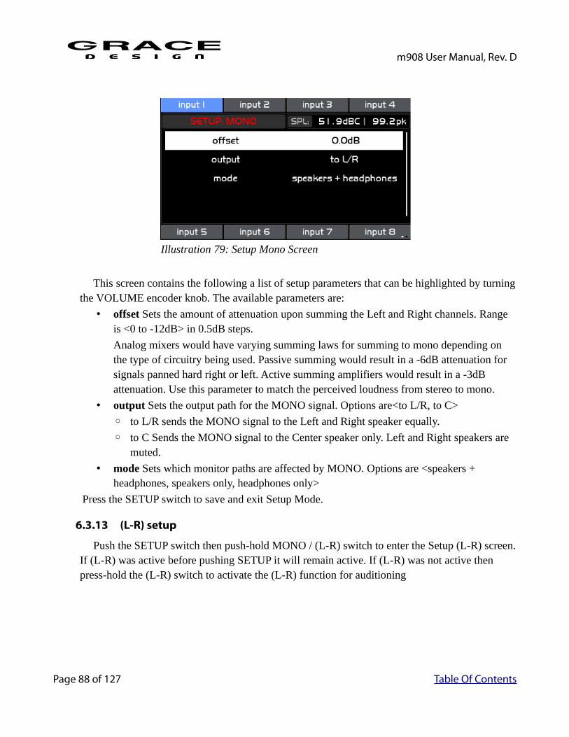
m908 User Manual, Rev. D
This screen contains the following a list of setup parameters that can be highlighted by turningthe VOLUME encoder knob. The available parameters are:
• offset Sets the amount of attenuation upon summing the Left and Right channels. Range is <0 to -12dB> in 0.5dB steps.
Analog mixers would have varying summing laws for summing to mono depending on the type of circuitry being used. Passive summing would result in a -6dB attenuation for signals panned hard right or left. Active summing amplifiers would result in a -3dB attenuation. Use this parameter to match the perceived loudness from stereo to mono.
• output Sets the output path for the MONO signal. Options are<to L/R, to C>
to L/R sends the MONO signal to the Left and Right speaker equally.
to C Sends the MONO signal to the Center speaker only. Left and Right speakers are muted.
• mode Sets which monitor paths are affected by MONO. Options are <speakers + headphones, speakers only, headphones only>
Press the SETUP switch to save and exit Setup Mode.
6.3.13 (L-R) setup
Push the SETUP switch then push-hold MONO / (L-R) switch to enter the Setup (L-R) screen.If (L-R) was active before pushing SETUP it will remain active. If (L-R) was not active then press-hold the (L-R) switch to activate the (L-R) function for auditioning
Page 88 of 127 Table Of Contents
Illustration 79: Setup Mono Screen
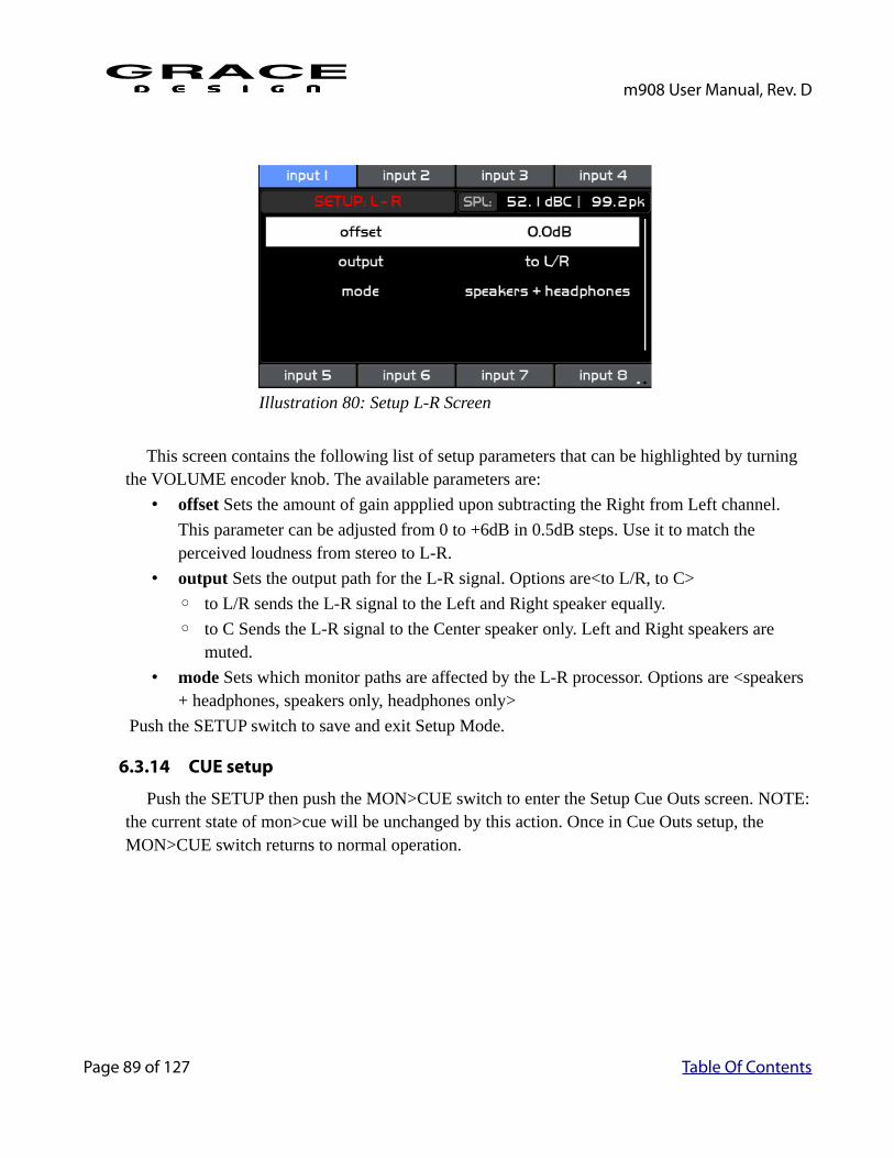
m908 User Manual, Rev. D
This screen contains the following list of setup parameters that can be highlighted by turning the VOLUME encoder knob. The available parameters are:
• offset Sets the amount of gain appplied upon subtracting the Right from Left channel.
This parameter can be adjusted from 0 to +6dB in 0.5dB steps. Use it to match the perceived loudness from stereo to L-R.
• output Sets the output path for the L-R signal. Options are<to L/R, to C>
to L/R sends the L-R signal to the Left and Right speaker equally.
to C Sends the L-R signal to the Center speaker only. Left and Right speakers are muted.
• mode Sets which monitor paths are affected by the L-R processor. Options are <speakers + headphones, speakers only, headphones only>
Push the SETUP switch to save and exit Setup Mode.
6.3.14 CUE setup
Push the SETUP then push the MON>CUE switch to enter the Setup Cue Outs screen. NOTE:the current state of mon>cue will be unchanged by this action. Once in Cue Outs setup, the MON>CUE switch returns to normal operation.
Page 89 of 127 Table Of Contents
Illustration 80: Setup L-R Screen
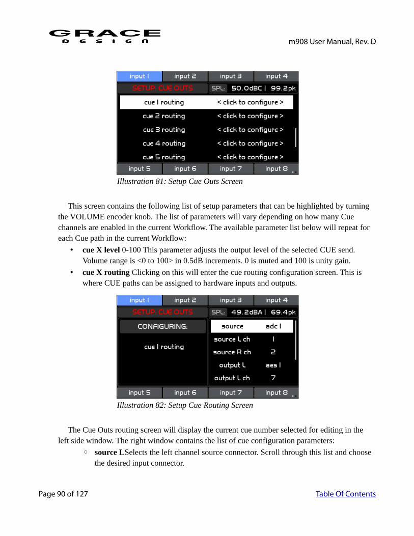
m908 User Manual, Rev. D
This screen contains the following list of setup parameters that can be highlighted by turning the VOLUME encoder knob. The list of parameters will vary depending on how many Cue channels are enabled in the current Workflow. The available parameter list below will repeat for each Cue path in the current Workflow:
• cue X level 0-100 This parameter adjusts the output level of the selected CUE send. Volume range is <0 to 100> in 0.5dB increments. 0 is muted and 100 is unity gain.
• cue X routing Clicking on this will enter the cue routing configuration screen. This is where CUE paths can be assigned to hardware inputs and outputs.
The Cue Outs routing screen will display the current cue number selected for editing in the left side window. The right window contains the list of cue configuration parameters:
source LSelects the left channel source connector. Scroll through this list and choose the desired input connector.
Page 90 of 127 Table Of Contents
Illustration 81: Setup Cue Outs Screen
Illustration 82: Setup Cue Routing Screen
m908 User Manual, Rev. D
source L ch Selects the left channel source connector channel. Scroll through this list and choose the desired input connector channel.
source R Selects the right channel source connector. Scroll through this list and choose the desired input connector.
source R ch Selects the right channel source connector channel. Scroll through this list and choose the desired input connector channel.
output L Selects the left channel output connector. Scroll through this list and choose the desired output connector.
output L ch Selects the left channel output connector channel. Scroll through this list and choose the desired output connector channel.
output R Selects the right channel output connector.
output R ch Selects the right channel output connector channel.
• mon>cue controls mon>cue function for this cue output.
disabled: the cue source is always the cue input regardless of the state of MON>CUE
left / right: When MON>CUE is activated, the cue source is switched to the left and right channels of the selected Control Room monitor source.
downmix: When MON>CUE is activated, the cue source is switched to a stereo downmix of the selected Control Room monitor source.
NOTE: To use the headphones for monitoring a Cue path when headphones are not enabled in the system workflow simply route the Cue outputs to CUE/CR EXT channels 7 and 8. The DAC channels that feed this connector also feed the headphone amplifier. The headphone volume is controlled by the Cue level in Setup>Cue.
Push the SETUP switch to save and exit Setup Mode.
6.3.15 MUTE setup
Push the SETUP switch then the MUTE switch to enter the Setup Mute screen.If MUTE was active before pushing SETUP it will remain active. If MUTE was not active then press the MUTE switch to activate the MUTE function for auditioning.
Page 91 of 127 Table Of Contents
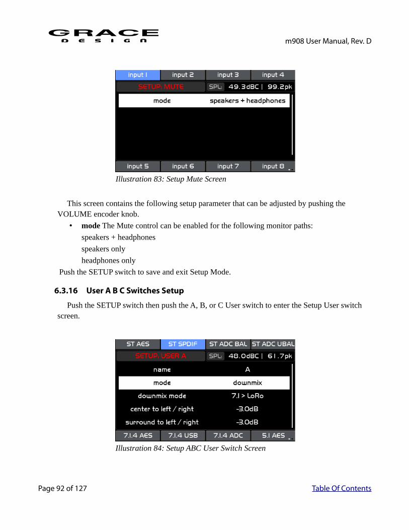
m908 User Manual, Rev. D
This screen contains the following setup parameter that can be adjusted by pushing the VOLUME encoder knob.
• mode The Mute control can be enabled for the following monitor paths:
speakers + headphones
speakers only
headphones only
Push the SETUP switch to save and exit Setup Mode.
6.3.16 User A m C Switches Setup
Push the SETUP switch then push the A, B, or C User switch to enter the Setup User switch screen.
Page 92 of 127 Table Of Contents
Illustration 83: Setup Mute Screen
Illustration 84: Setup ABC User Switch Screen
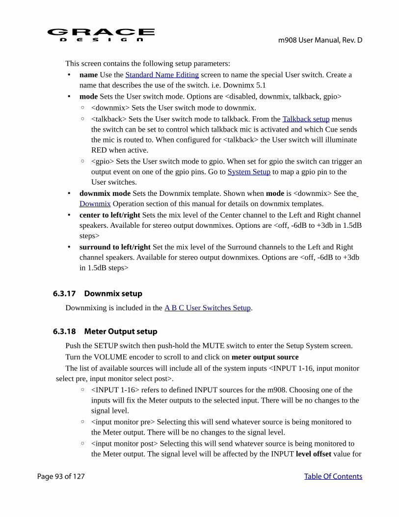
m908 User Manual, Rev. D
This screen contains the following setup parameters:
• name Use the Standard Name Editing screen to name the special User switch. Create a name that describes the use of the switch. i.e. Downimx 5.1
• mode Sets the User switch mode. Options are <disabled, downmix, talkback, gpio>
<downmix> Sets the User switch mode to downmix.
<talkback> Sets the User switch mode to talkback. From the Talkback setup menus the switch can be set to control which talkback mic is activated and which Cue sends the mic is routed to. When configured for <talkback> the User switch will illuminate RED when active.
<gpio> Sets the User switch mode to gpio. When set for gpio the switch can trigger anoutput event on one of the gpio pins. Go to System Setup to map a gpio pin to the User switches.
• downmix mode Sets the Downmix template. Shown when mode is <downmix> See the Downmix Operation section of this manual for details on downmix templates.
• center to left/right Sets the mix level of the Center channel to the Left and Right channelspeakers. Available for stereo output downmixes. Options are <off, -6dB to +3db in 1.5dBsteps>
• surround to left/right Set the mix level of the Surround channels to the Left and Right channel speakers. Available for stereo output downmixes. Options are <off, -6dB to +3db in 1.5dB steps>
6.3.17 Downmix setup
Downmixing is included in the A B C User Switches Setup.
6.3.18 Meter Output setup
Push the SETUP switch then push-hold the MUTE switch to enter the Setup System screen.
Turn the VOLUME encoder to scroll to and click on meter output source
The list of available sources will include all of the system inputs <INPUT 1-16, input monitor select pre, input monitor select post>.
<INPUT 1-16> refers to defined INPUT sources for the m908. Choosing one of the inputs will fix the Meter outputs to the selected input. There will be no changes to the signal level.
<input monitor pre> Selecting this will send whatever source is being monitored to the Meter output. There will be no changes to the signal level.
<input monitor post> Selecting this will send whatever source is being monitored to the Meter output. The signal level will be affected by the INPUT level offset value for
Page 93 of 127 Table Of Contents
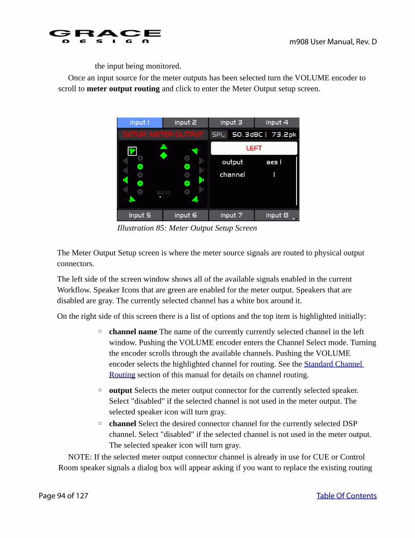
m908 User Manual, Rev. D
the input being monitored.
Once an input source for the meter outputs has been selected turn the VOLUME encoder to scroll to meter output routing and click to enter the Meter Output setup screen.
The Meter Output Setup screen is where the meter source signals are routed to physical output connectors.
The left side of the screen window shows all of the available signals enabled in the current Workflow. Speaker Icons that are green are enabled for the meter output. Speakers that are disabled are gray. The currently selected channel has a white box around it.
On the right side of this screen there is a list of options and the top item is highlighted initially:
channel name The name of the currently currently selected channel in the left window. Pushing the VOLUME encoder enters the Channel Select mode. Turningthe encoder scrolls through the available channels. Pushing the VOLUME encoder selects the highlighted channel for routing. See the Standard Channel Routing section of this manual for details on channel routing.
output Selects the meter output connector for the currently selected speaker. Select "disabled" if the selected channel is not used in the meter output. The selected speaker icon will turn gray.
channel Select the desired connector channel for the currently selected DSP channel. Select "disabled" if the selected channel is not used in the meter output. The selected speaker icon will turn gray.
NOTE: If the selected meter output connector channel is already in use for CUE or Control Room speaker signals a dialog box will appear asking if you want to replace the existing routing
Page 94 of 127 Table Of Contents
Illustration 85: Meter Output Setup Screen
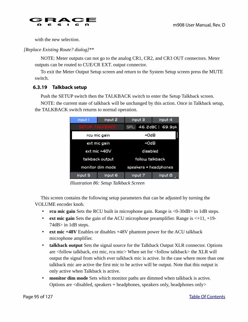
m908 User Manual, Rev. D
with the new selection.
[Replace Existing Route? dialog]**
NOTE: Meter outputs can not go to the analog CR1, CR2, and CR3 OUT connectors. Meter outputs can be routed to CUE/CR EXT. output connector.
To exit the Meter Output Setup screen and return to the System Setup screen press the MUTE switch.
6.3.19 Talkback setup
Push the SETUP switch then the TALKBACK switch to enter the Setup Talkback screen.
NOTE: the current state of talkback will be unchanged by this action. Once in Talkback setup, the TALKBACK switch returns to normal operation.
This screen contains the following setup parameters that can be adjusted by turning the VOLUME encoder knob.
• rcu mic gain Sets the RCU built in microphone gain. Range is <0-30dB> in 1dB steps.
• ext mic gain Sets the gain of the ACU microphone preamplifier. Range is <+11, +19-74dB> in 1dB steps.
• ext mic +48V Enables or disables +48V phantom power for the ACU talkback microphone amplifier.
• talkback output Sets the signal source for the Talkback Output XLR connector. Options are <follow talkback, ext mic, rcu mic> When set for <follow talkback> the XLR will output the signal from which ever talkback mic is active. In the case where more than onetalkback mic are active the first mic to be active will be output. Note that this output is only active when Talkback is active.
• monitor dim mode Sets which monitor paths are dimmed when talkback is active. Options are <disabled, speakers + headphones, speakers only, headphones only>
Page 95 of 127 Table Of Contents
Illustration 86: Setup Talkback Screen
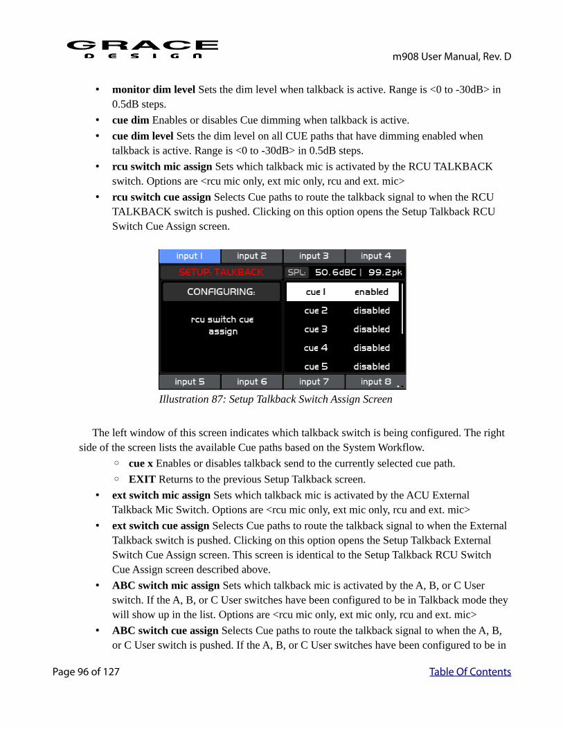
m908 User Manual, Rev. D
• monitor dim level Sets the dim level when talkback is active. Range is <0 to -30dB> in 0.5dB steps.
• cue dim Enables or disables Cue dimming when talkback is active.
• cue dim level Sets the dim level on all CUE paths that have dimming enabled when talkback is active. Range is <0 to -30dB> in 0.5dB steps.
• rcu switch mic assign Sets which talkback mic is activated by the RCU TALKBACK switch. Options are <rcu mic only, ext mic only, rcu and ext. mic>
• rcu switch cue assign Selects Cue paths to route the talkback signal to when the RCU TALKBACK switch is pushed. Clicking on this option opens the Setup Talkback RCU Switch Cue Assign screen.
The left window of this screen indicates which talkback switch is being configured. The right side of the screen lists the available Cue paths based on the System Workflow.
cue x Enables or disables talkback send to the currently selected cue path.
EXIT Returns to the previous Setup Talkback screen.
• ext switch mic assign Sets which talkback mic is activated by the ACU External Talkback Mic Switch. Options are <rcu mic only, ext mic only, rcu and ext. mic>
• ext switch cue assign Selects Cue paths to route the talkback signal to when the External Talkback switch is pushed. Clicking on this option opens the Setup Talkback External Switch Cue Assign screen. This screen is identical to the Setup Talkback RCU Switch Cue Assign screen described above.
• ABC switch mic assign Sets which talkback mic is activated by the A, B, or C User switch. If the A, B, or C User switches have been configured to be in Talkback mode they will show up in the list. Options are <rcu mic only, ext mic only, rcu and ext. mic>
• ABC switch cue assign Selects Cue paths to route the talkback signal to when the A, B, or C User switch is pushed. If the A, B, or C User switches have been configured to be in
Page 96 of 127 Table Of Contents
Illustration 87: Setup Talkback Switch Assign Screen
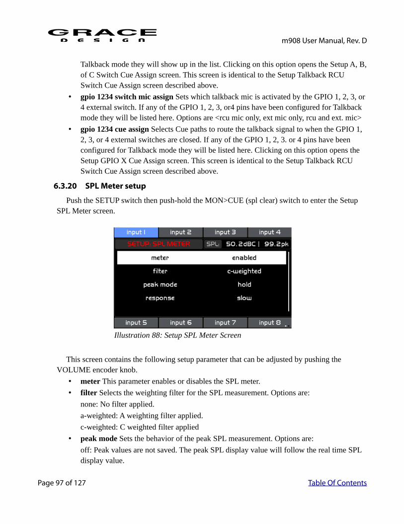
m908 User Manual, Rev. D
Talkback mode they will show up in the list. Clicking on this option opens the Setup A, B,of C Switch Cue Assign screen. This screen is identical to the Setup Talkback RCU Switch Cue Assign screen described above.
• gpio 1234 switch mic assign Sets which talkback mic is activated by the GPIO 1, 2, 3, or4 external switch. If any of the GPIO 1, 2, 3, or4 pins have been configured for Talkback mode they will be listed here. Options are <rcu mic only, ext mic only, rcu and ext. mic>
• gpio 1234 cue assign Selects Cue paths to route the talkback signal to when the GPIO 1, 2, 3, or 4 external switches are closed. If any of the GPIO 1, 2, 3. or 4 pins have been configured for Talkback mode they will be listed here. Clicking on this option opens the Setup GPIO X Cue Assign screen. This screen is identical to the Setup Talkback RCU Switch Cue Assign screen described above.
6.3.20 SPL Meter setup
Push the SETUP switch then push-hold the MON>CUE (spl clear) switch to enter the Setup SPL Meter screen.
This screen contains the following setup parameter that can be adjusted by pushing the VOLUME encoder knob.
• meter This parameter enables or disables the SPL meter.
• filter Selects the weighting filter for the SPL measurement. Options are:
none: No filter applied.
a-weighted: A weighting filter applied.
c-weighted: C weighted filter applied
• peak mode Sets the behavior of the peak SPL measurement. Options are:
off: Peak values are not saved. The peak SPL display value will follow the real time SPL display value.
Page 97 of 127 Table Of Contents
Illustration 88: Setup SPL Meter Screen
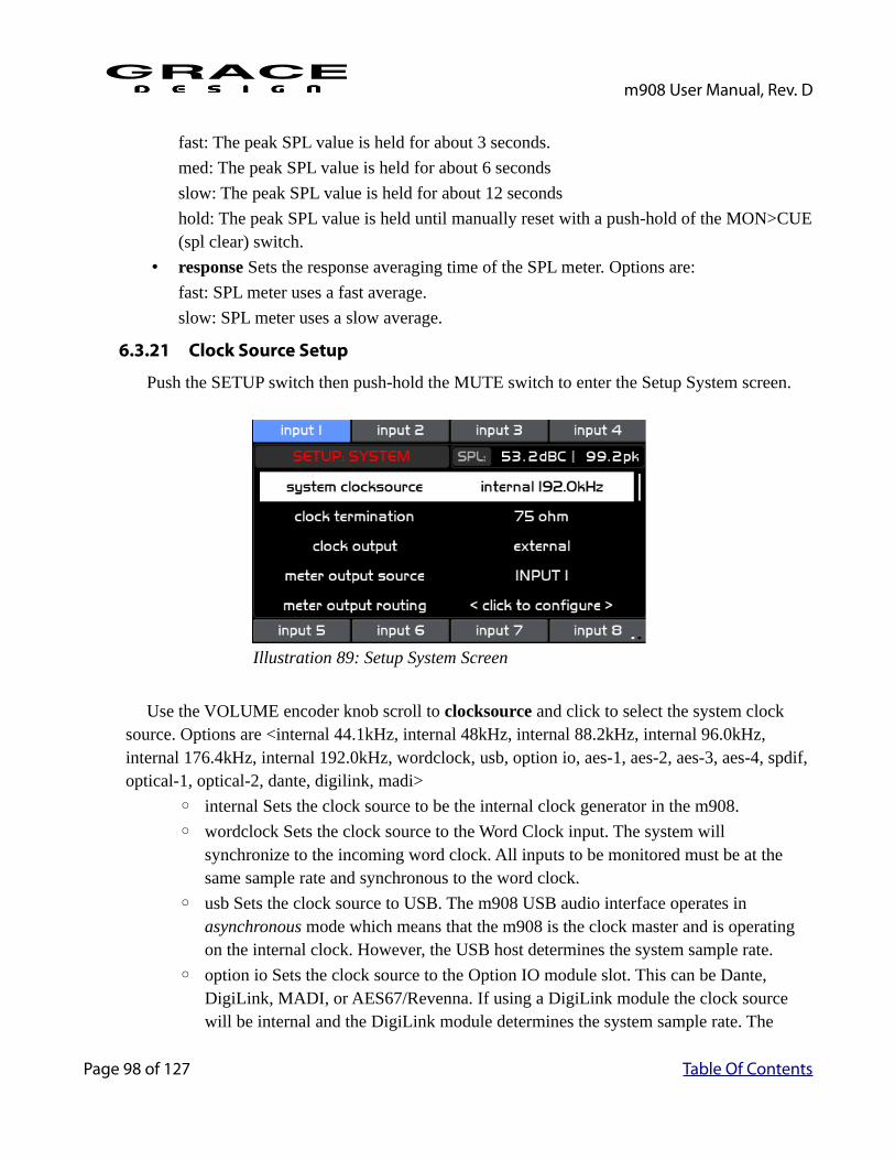
m908 User Manual, Rev. D
fast: The peak SPL value is held for about 3 seconds.
med: The peak SPL value is held for about 6 seconds
slow: The peak SPL value is held for about 12 seconds
hold: The peak SPL value is held until manually reset with a push-hold of the MON>CUE(spl clear) switch.
• response Sets the response averaging time of the SPL meter. Options are:
fast: SPL meter uses a fast average.
slow: SPL meter uses a slow average.
6.3.21 Clock Source Setup
Push the SETUP switch then push-hold the MUTE switch to enter the Setup System screen.
Use the VOLUME encoder knob scroll to clocksource and click to select the system clock source. Options are <internal 44.1kHz, internal 48kHz, internal 88.2kHz, internal 96.0kHz, internal 176.4kHz, internal 192.0kHz, wordclock, usb, option io, aes-1, aes-2, aes-3, aes-4, spdif, optical-1, optical-2, dante, digilink, madi>
internal Sets the clock source to be the internal clock generator in the m908.
wordclock Sets the clock source to the Word Clock input. The system will synchronize to the incoming word clock. All inputs to be monitored must be at the same sample rate and synchronous to the word clock.
usb Sets the clock source to USB. The m908 USB audio interface operates in asynchronous mode which means that the m908 is the clock master and is operating on the internal clock. However, the USB host determines the system sample rate.
option io Sets the clock source to the Option IO module slot. This can be Dante, DigiLink, MADI, or AES67/Revenna. If using a DigiLink module the clock source will be internal and the DigiLink module determines the system sample rate. The
Page 98 of 127 Table Of Contents
Illustration 89: Setup System Screen
m908 User Manual, Rev. D
system will slave to all other types of IO modules.
aes-1-3 Sets one of the AES3 inputs as the clock source. AES3 1-3 are 8 channel interfaces which each contain 4 AES3 signals. The system will synchronize to the lowest numbered valid signal. All four signals must be at the same sample rate and must be synchronous to each other.
aes-4 Sets the aes-4 (XLR) as the clock source.
spdif Sets the clock source to the SPDIF coaxial input.
optical-1 Sets the clock source to the optical connector 1 (can be ADAT or TOSLINK)
optical-2 Sets the clock source to the optical connector 2 (can be ADAT or TOSLINK)
6.3.22 Word Clock Termination Setup
Push the SETUP switch then push-hold the MUTE switch to enter the Setup System screen.
Turn the VOLUME encoder to scroll to and click on clock termination
Options are <48kΩ , 75Ω>.
Push the Setup switch to save changes and exit Setup Mode.
6.3.23 Word Clock Output Setup
Push the SETUP switch then push-hold the MUTE switch to enter the Setup System screen.
Turn the VOLUME encoder to scroll to and click on clock output
Options are <external, system clock,>
<external> the signal on the word clock output BNC connector will be a buffered copy of the signal on the word clock input BNC.
<system clock> the signal on the word clock output BNC connector will be the internal system clock source.
Note: If the system clock source is set to word clock and the word clock output is set to system clock, then the output clock signal will be a re-clocked version of the input clock.
Push the Setup switch to save changes and exit Setup Mode.
6.3.24 GPIO Setup
The m908 has 4 GPIO (General Purpose Input/Output) pins on various rear panel connectors. These pins can be configured as logic level inputs or outputs and can be mapped to various functions. The GPIO pins can be programmed to operate at 3.3V or 5.0V by moving jumpers on the PCB. Built in pull up resistors allow for the use of external switch closures to trigger input events.
GPIO configuration is accessed in the System Setup screen.
The table below contains the available input and output functions.
Page 99 of 127 Table Of Contents
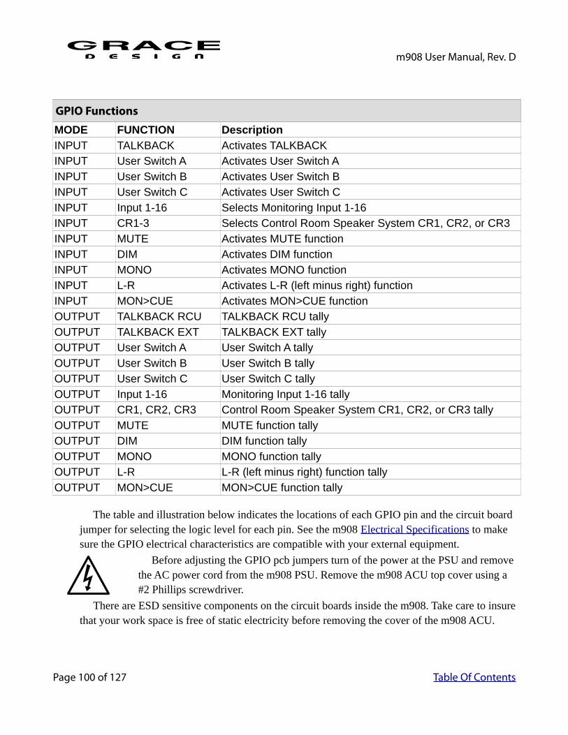
m908 User Manual, Rev. D
GPIO Functions
MODE FUNCTION Description
INPUT TALKBACK Activates TALKBACKINPUT User Switch A Activates User Switch A
INPUT User Switch B Activates User Switch BINPUT User Switch C Activates User Switch C
INPUT Input 1-16 Selects Monitoring Input 1-16INPUT CR1-3 Selects Control Room Speaker System CR1, CR2, or CR3
INPUT MUTE Activates MUTE functionINPUT DIM Activates DIM function
INPUT MONO Activates MONO functionINPUT L-R Activates L-R (left minus right) function
INPUT MON>CUE Activates MON>CUE functionOUTPUT TALKBACK RCU TALKBACK RCU tally
OUTPUT TALKBACK EXT TALKBACK EXT tallyOUTPUT User Switch A User Switch A tally
OUTPUT User Switch B User Switch B tallyOUTPUT User Switch C User Switch C tally
OUTPUT Input 1-16 Monitoring Input 1-16 tallyOUTPUT CR1, CR2, CR3 Control Room Speaker System CR1, CR2, or CR3 tally
OUTPUT MUTE MUTE function tallyOUTPUT DIM DIM function tally
OUTPUT MONO MONO function tallyOUTPUT L-R L-R (left minus right) function tally
OUTPUT MON>CUE MON>CUE function tally
The table and illustration below indicates the locations of each GPIO pin and the circuit board jumper for selecting the logic level for each pin. See the m908 Electrical Specifications to make sure the GPIO electrical characteristics are compatible with your external equipment.
Before adjusting the GPIO pcb jumpers turn of the power at the PSU and removethe AC power cord from the m908 PSU. Remove the m908 ACU top cover using a #2 Phillips screwdriver.
There are ESD sensitive components on the circuit boards inside the m908. Take care to insurethat your work space is free of static electricity before removing the cover of the m908 ACU.
Page 100 of 127 Table Of Contents
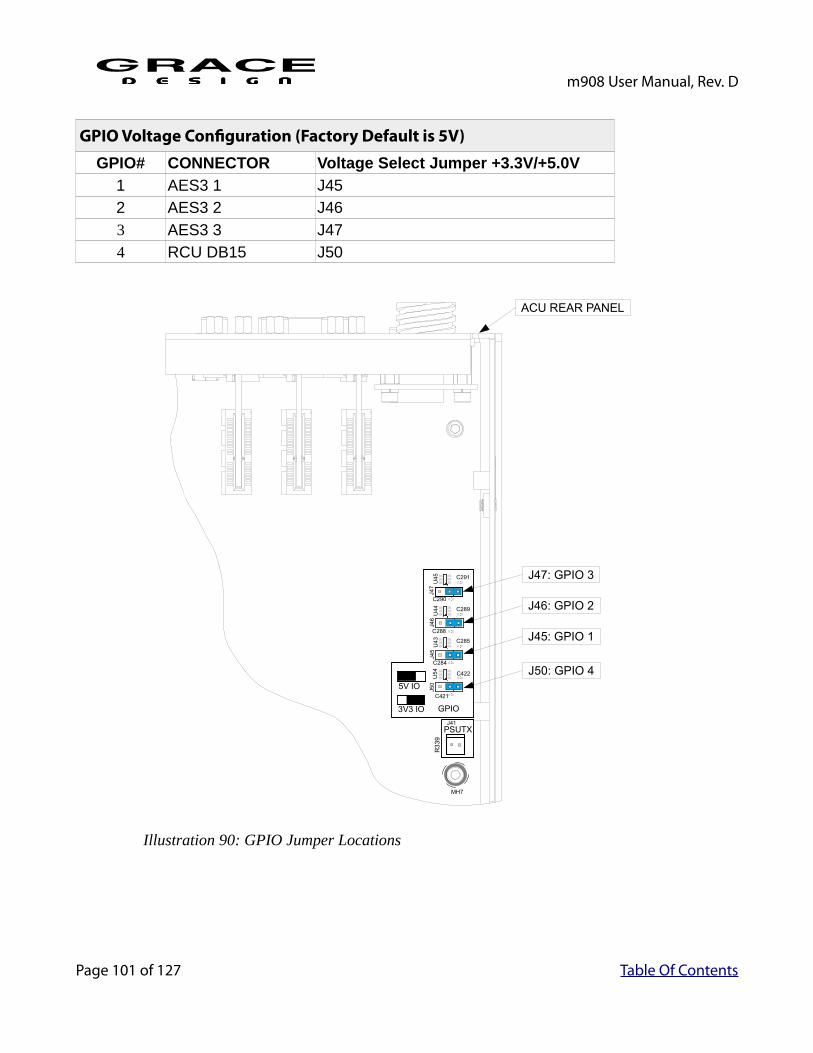
m908 User Manual, Rev. D
GPIO Voltage Confguration (Factory Default is 5V)
GPIO# CONNECTOR Voltage Select Jumper +3.3V/+5.0V
1 AES3 1 J452 AES3 2 J463 AES3 3 J474 RCU DB15 J50
Page 101 of 127 Table Of Contents
R3
39
MH7
5V IO
3V3 IO
J50
C421
J45
C284
U5
4U
43
J46
C288
U4
4
PSUTXJ41
GPIO
C422
C285
C289
J47
C290
U4
5 C291
ACU REAR PANEL
J47: GPIO 3
J46: GPIO 2
J45: GPIO 1
J50: GPIO 4
Illustration 90: GPIO Jumper Locations
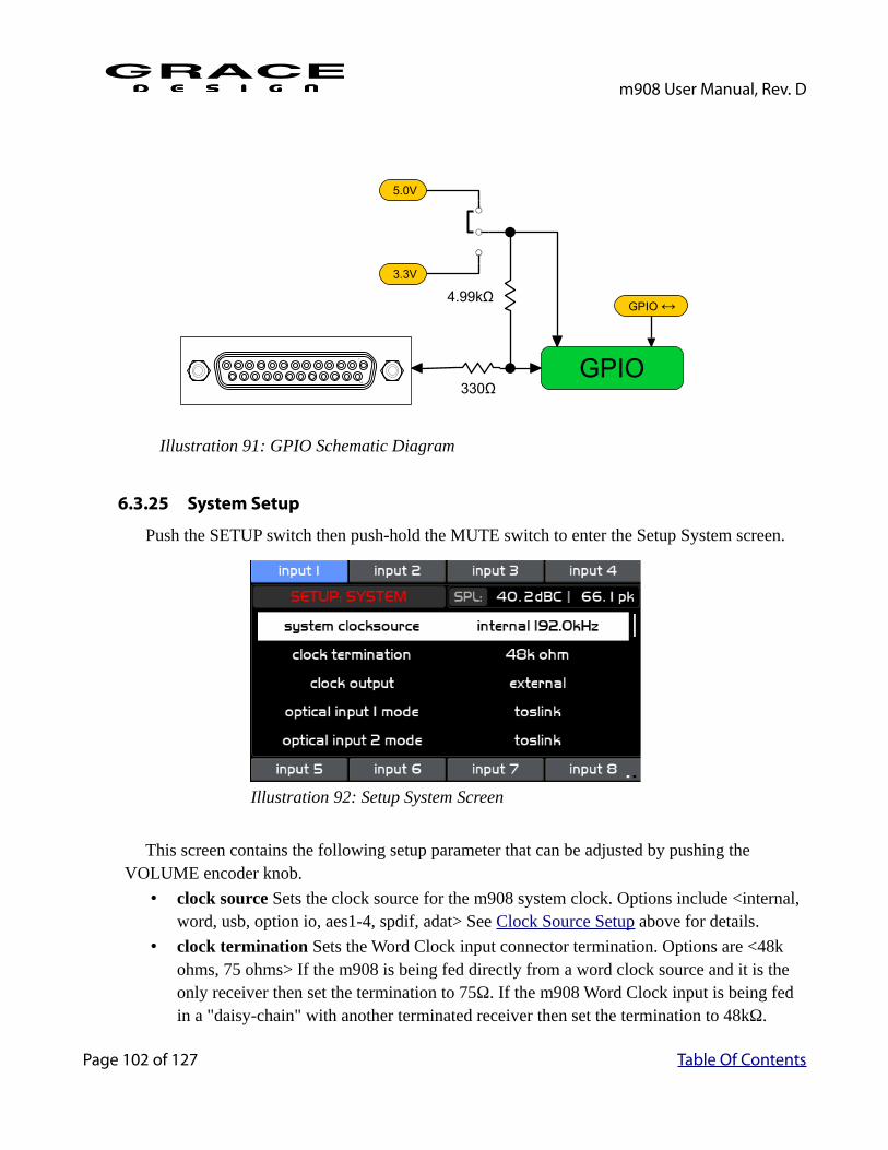
m908 User Manual, Rev. D
6.3.25 System Setup
Push the SETUP switch then push-hold the MUTE switch to enter the Setup System screen.
This screen contains the following setup parameter that can be adjusted by pushing the VOLUME encoder knob.
• clock source Sets the clock source for the m908 system clock. Options include <internal, word, usb, option io, aes1-4, spdif, adat> See Clock Source Setup above for details.
• clock termination Sets the Word Clock input connector termination. Options are <48k ohms, 75 ohms> If the m908 is being fed directly from a word clock source and it is the only receiver then set the termination to 75Ω. If the m908 Word Clock input is being fed in a "daisy-chain" with another terminated receiver then set the termination to 48kΩ.
Page 102 of 127 Table Of Contents
330Ω
GPIO ↔
14
1
GPIO
5.0V
3.3V
4.99kΩ
Illustration 91: GPIO Schematic Diagram
Illustration 92: Setup System Screen
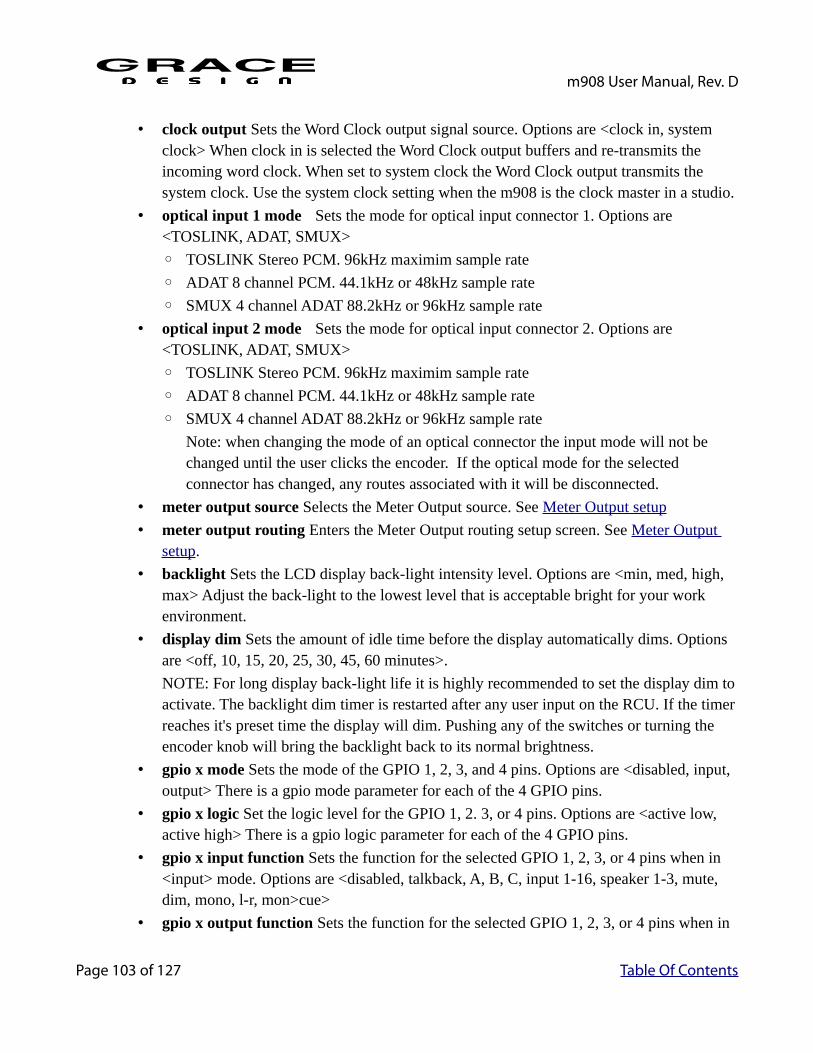
m908 User Manual, Rev. D
• clock output Sets the Word Clock output signal source. Options are <clock in, system clock> When clock in is selected the Word Clock output buffers and re-transmits the incoming word clock. When set to system clock the Word Clock output transmits the system clock. Use the system clock setting when the m908 is the clock master in a studio.
• optical input 1 mode Sets the mode for optical input connector 1. Options are <TOSLINK, ADAT, SMUX>
TOSLINK Stereo PCM. 96kHz maximim sample rate
ADAT 8 channel PCM. 44.1kHz or 48kHz sample rate
SMUX 4 channel ADAT 88.2kHz or 96kHz sample rate
• optical input 2 mode Sets the mode for optical input connector 2. Options are <TOSLINK, ADAT, SMUX>
TOSLINK Stereo PCM. 96kHz maximim sample rate
ADAT 8 channel PCM. 44.1kHz or 48kHz sample rate
SMUX 4 channel ADAT 88.2kHz or 96kHz sample rate
Note: when changing the mode of an optical connector the input mode will not be changed until the user clicks the encoder. If the optical mode for the selected connector has changed, any routes associated with it will be disconnected.
• meter output source Selects the Meter Output source. See Meter Output setup
• meter output routing Enters the Meter Output routing setup screen. See Meter Output setup.
• backlight Sets the LCD display back-light intensity level. Options are <min, med, high, max> Adjust the back-light to the lowest level that is acceptable bright for your work environment.
• display dim Sets the amount of idle time before the display automatically dims. Options are <off, 10, 15, 20, 25, 30, 45, 60 minutes>.
NOTE: For long display back-light life it is highly recommended to set the display dim toactivate. The backlight dim timer is restarted after any user input on the RCU. If the timerreaches it's preset time the display will dim. Pushing any of the switches or turning the encoder knob will bring the backlight back to its normal brightness.
• gpio x mode Sets the mode of the GPIO 1, 2, 3, and 4 pins. Options are <disabled, input, output> There is a gpio mode parameter for each of the 4 GPIO pins.
• gpio x logic Set the logic level for the GPIO 1, 2. 3, or 4 pins. Options are <active low, active high> There is a gpio logic parameter for each of the 4 GPIO pins.
• gpio x input function Sets the function for the selected GPIO 1, 2, 3, or 4 pins when in <input> mode. Options are <disabled, talkback, A, B, C, input 1-16, speaker 1-3, mute, dim, mono, l-r, mon>cue>
• gpio x output function Sets the function for the selected GPIO 1, 2, 3, or 4 pins when in
Page 103 of 127 Table Of Contents
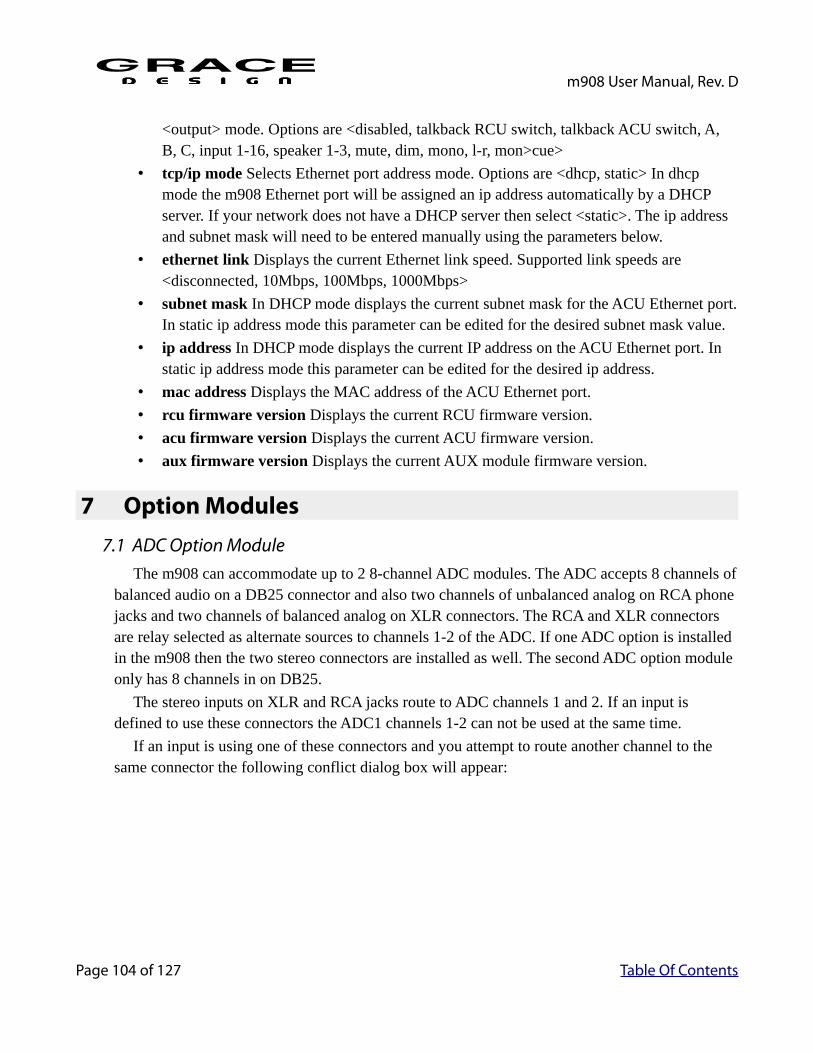
m908 User Manual, Rev. D
<output> mode. Options are <disabled, talkback RCU switch, talkback ACU switch, A, B, C, input 1-16, speaker 1-3, mute, dim, mono, l-r, mon>cue>
• tcp/ip mode Selects Ethernet port address mode. Options are <dhcp, static> In dhcp mode the m908 Ethernet port will be assigned an ip address automatically by a DHCP server. If your network does not have a DHCP server then select <static>. The ip address and subnet mask will need to be entered manually using the parameters below.
• ethernet link Displays the current Ethernet link speed. Supported link speeds are <disconnected, 10Mbps, 100Mbps, 1000Mbps>
• subnet mask In DHCP mode displays the current subnet mask for the ACU Ethernet port.In static ip address mode this parameter can be edited for the desired subnet mask value.
• ip address In DHCP mode displays the current IP address on the ACU Ethernet port. In static ip address mode this parameter can be edited for the desired ip address.
• mac address Displays the MAC address of the ACU Ethernet port.
• rcu firmware version Displays the current RCU firmware version.
• acu firmware version Displays the current ACU firmware version.
• aux firmware version Displays the current AUX module firmware version.
7 Option Modules 7.1 ADC Option Module
The m908 can accommodate up to 2 8-channel ADC modules. The ADC accepts 8 channels ofbalanced audio on a DB25 connector and also two channels of unbalanced analog on RCA phone jacks and two channels of balanced analog on XLR connectors. The RCA and XLR connectors are relay selected as alternate sources to channels 1-2 of the ADC. If one ADC option is installed in the m908 then the two stereo connectors are installed as well. The second ADC option module only has 8 channels in on DB25.
The stereo inputs on XLR and RCA jacks route to ADC channels 1 and 2. If an input is defined to use these connectors the ADC1 channels 1-2 can not be used at the same time.
If an input is using one of these connectors and you attempt to route another channel to the same connector the following conflict dialog box will appear:
Page 104 of 127 Table Of Contents
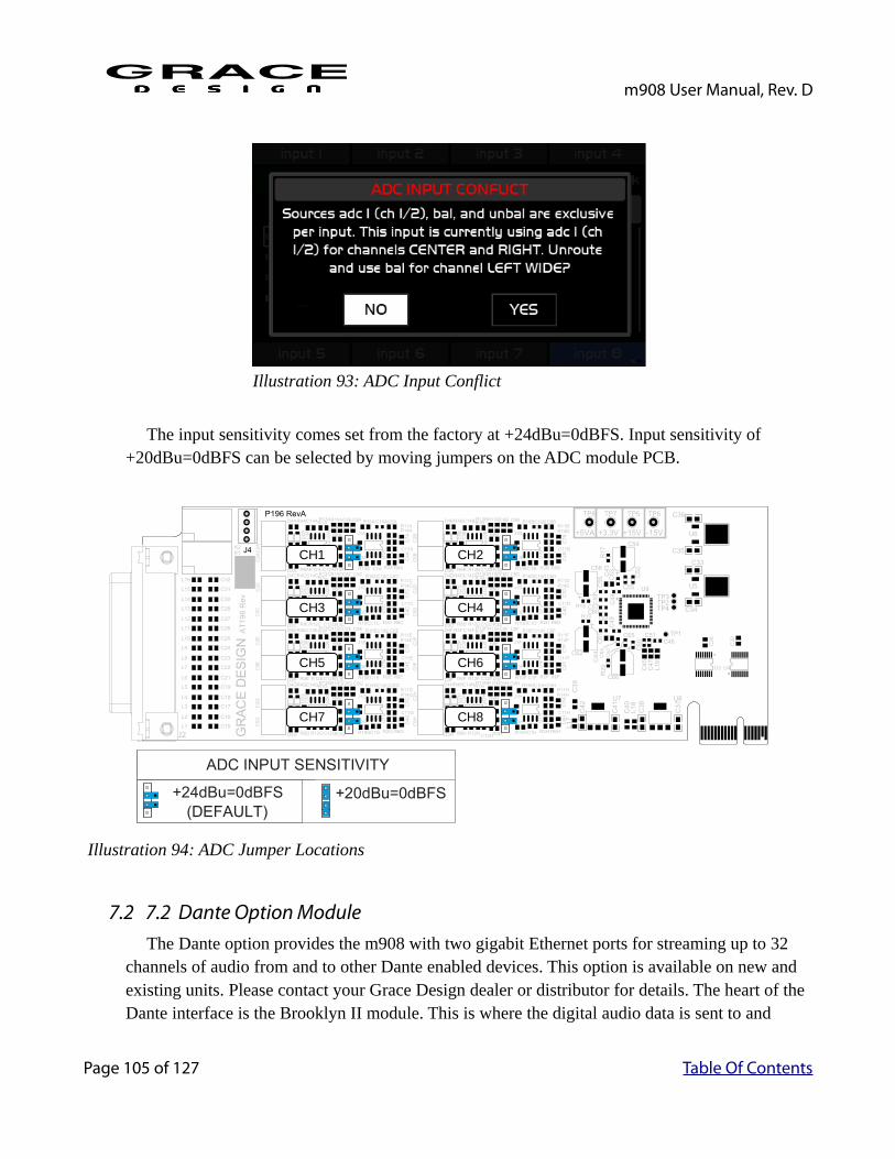
m908 User Manual, Rev. D
The input sensitivity comes set from the factory at +24dBu=0dBFS. Input sensitivity of +20dBu=0dBFS can be selected by moving jumpers on the ADC module PCB.
7.2 7.2 Dante Option ModuleThe Dante option provides the m908 with two gigabit Ethernet ports for streaming up to 32
channels of audio from and to other Dante enabled devices. This option is available on new and existing units. Please contact your Grace Design dealer or distributor for details. The heart of the Dante interface is the Brooklyn II module. This is where the digital audio data is sent to and
Page 105 of 127 Table Of Contents
+5VA
TP8
C60C57
C58
R1GR13G
R1E
R1C
R1A
R13E
R13CC12A
R13A
C12G
C12E
C12C
U1
C
R5
C
R4H
R8H
R4F
R8F
R8D
R5
D
U1
D R18
R4D
R4B
R8B
R5
G
R3G
R7
GU
2G R9G
R15GR3E
C8G
R10G
C13G
C1G R2G
U1
G
J1G
C9GR10E
R16GC10G
C1E R2E
R5
ER
7E
U2
E R9E
R15ER3C
C8E
C13E
J1E
U1
E
R16EC9ER10C
C13C
C10E C6E
C1C R2C
R6G
C5
H
C4
G
C11G
C6G
R6E
C7
G C2
HR14GR11G
D3H
D4HD3F
C5
F
C4
E
C11E
C7
E
R6C
R14ER11E
C2
F
C4
C
C5
D
D4FD3D
D1
H
R12H
R5
H
D2
HC
3H
C14HR12F
R7
HU
2H
R1HR13H
C12HR3H
C13H
R9H
R15HC12F R3F
C8H C9H
D1
FD
2F
C3
F
R5
FU
2F
OPA1662
D1
D
C14FR12D
R1FR13F
R7
F
R9F
C13F
R15FC8FR3DC12D
C9F
C13D
R10HC1H R2H
U1
H
J1H
R16H
R10F C1F
C10H
R2F
R6H
L17C
4H
C11H
C6H
R6F
C7
H
C42
R14HR11H C
39
U1
F
J1F
R10D
R16FC10F
C1D R2D
R14FR11F
C4
F
C11F
C7
F
C62
C6F
R6D
C4
D
R19
D2
DC
3D
U2
D
C14DR12B
R1DR13D
R7
D
R9D
R15DR3BC12B
C8D
D1
BD
2B
C3
B
C14BR1B
R5
BR
7B
U2
B
R13BR15B
R9B
C8B
J1D
C9DR10B
C10DR16D
C1B R2B
C11D
C6D
C7
D
R14DR11D
R6B
C13B U1
BJ1B
C9B R16B
C4
B
C11B
C10B C6B
C7
B
R11BR14B
R7
CU
2C R9C
R15CR3A
C8C
J1C
C9CR10A
R16CC10C
C1A
R5
AR
7A
U2
A R9A
R15A
C13A
J1A
C8A R16AC9A C10A
C11C
C7
C
R2A
C6CR11C
C2
DR14C
R6A
C5
B
D4DD3B
U1
A
C4
A
C6A
C7
A
R11A
C11A
C2
B
R14A
D4B
AT
19
6 R
ev
L1
14
J2
L2
1
L3
L4
L5
L6
L7
L8
L9
L10
L11
L12
L13
C15
C21
C5
GC16
C17 C2
G
C18
GR
AC
E D
ES
IGN
C19
C22
C23
C5
E
C24
C25
C2
E
C26
C27
C5
CC29
D3G
D4GD3E
D1
G
R8G R12G
D2
G
R4GR8E
C3
G
C14GR12E
D4ED3C
D1
ED
2E
C3
E
R4ER8C
D1
C
C14ER12C
C30
C31 C2
C
C32D4C
K1K2
C5
AC
2A
J4
D3A
D4A
D2
CC
3C
R4CC14CR8A
D1
A
R12A
D2
A
R4A
C3
A
C14A
25 13
Q1
L14
L15
L16
TP4
U4
R2
0
C41
C66
C4
4C
64C
67
C4
0
U7
C61
C63
C4
9
C65L1
8C
38C
45
L19
C47
C3
7
U8
U3
C50
C51C46
TP1
C28
C34
C20
C59
C48
C56
C55
C5
3C
43R
17
TP7
+3.3V +15V
TP5
TP2TP3
U9
C52
U5
C54C35
TP6
-15V
C36
C33
U6
P196 RevA
CH4
CH5 CH6
CH7 CH8
CH3
CH2CH1
ADC INPUT SENSITIVITY
+20dBu=0dBFS(DEFAULT)
+24dBu=0dBFS
Illustration 94: ADC Jumper Locations
Illustration 93: ADC Input Conflict
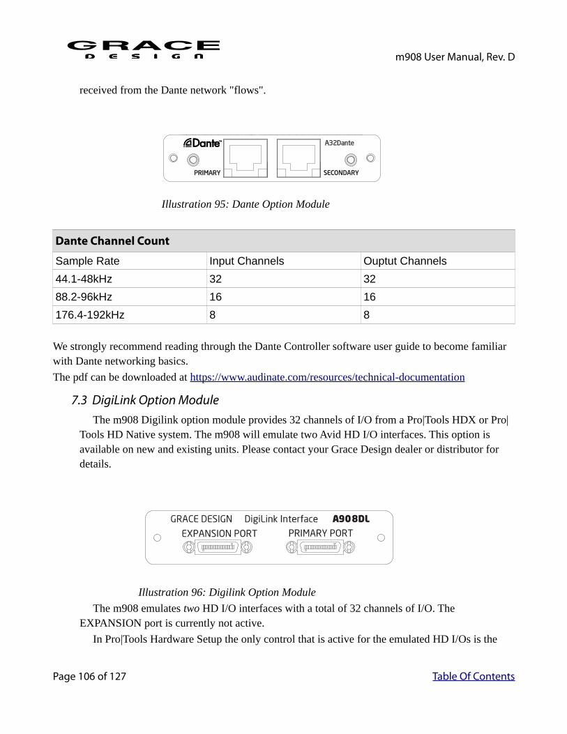
m908 User Manual, Rev. D
received from the Dante network "flows".
Dante Channel Count
Sample Rate Input Channels Ouptut Channels
44.1-48kHz 32 32
88.2-96kHz 16 16
176.4-192kHz 8 8
We strongly recommend reading through the Dante Controller software user guide to become familiar with Dante networking basics.
The pdf can be downloaded at https://www.audinate.com/resources/technical-documentation
7.3 DigiLink Option ModuleThe m908 Digilink option module provides 32 channels of I/O from a Pro|Tools HDX or Pro|
Tools HD Native system. The m908 will emulate two Avid HD I/O interfaces. This option is available on new and existing units. Please contact your Grace Design dealer or distributor for details.
The m908 emulates two HD I/O interfaces with a total of 32 channels of I/O. The EXPANSION port is currently not active.
In Pro|Tools Hardware Setup the only control that is active for the emulated HD I/Os is the
Page 106 of 127 Table Of Contents
Illustration 95: Dante Option Module
Illustration 96: Digilink Option Module
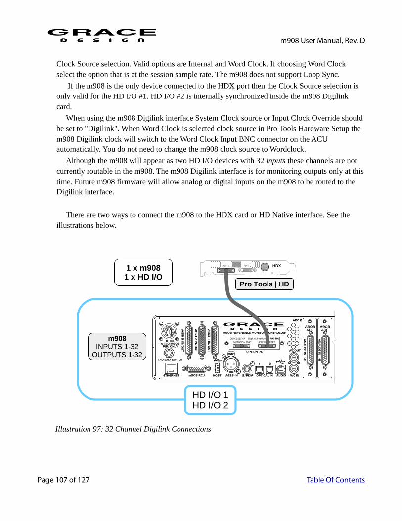
m908 User Manual, Rev. D
Clock Source selection. Valid options are Internal and Word Clock. If choosing Word Clock select the option that is at the session sample rate. The m908 does not support Loop Sync.
If the m908 is the only device connected to the HDX port then the Clock Source selection is only valid for the HD I/O #1. HD I/O #2 is internally synchronized inside the m908 Digilink card.
When using the m908 Digilink interface System Clock source or Input Clock Override should be set to "Digilink". When Word Clock is selected clock source in Pro|Tools Hardware Setup the m908 Digilink clock will switch to the Word Clock Input BNC connector on the ACU automatically. You do not need to change the m908 clock source to Wordclock.
Although the m908 will appear as two HD I/O devices with 32 inputs these channels are not currently routable in the m908. The m908 Digilink interface is for monitoring outputs only at thistime. Future m908 firmware will allow analog or digital inputs on the m908 to be routed to the Digilink interface.
There are two ways to connect the m908 to the HDX card or HD Native interface. See the illustrations below.
Page 107 of 127 Table Of Contents
m908INPUTS 1-32
OUTPUTS 1-32
m908 RCU
AE
S3
1 IN
/OU
T
DC INA140-M908
ETHERNET AES3 IN S/PDIF OPTICAL IN AUDIO WC IN
WC OUTOPTION I/O
AE
S3
3 IN
/OU
T
AE
S3
2 IN
/OU
T
HOST
TALKBACK SWITCH
ADC 2
m908 REFERENCE MONITOR CONTROLLER
PSU ONLY
1 2
A908
AN
ALO
G IN
1-8
ADCA908
AN
ALO
G IN
1-8
ADC
14
1 14
1 14
1
9
1
14
1 14
1
865
213
1 x m9081 x HD I/O
PORT 1 PORT 2 HDX
Pro Tools | HD
HD I/O 1HD I/O 2
Illustration 97: 32 Channel Digilink Connections
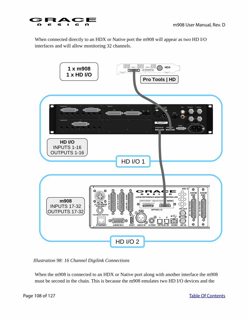
m908 User Manual, Rev. D
When connected directly to an HDX or Native port the m908 will appear as two HD I/O interfaces and will allow monitoring 32 channels.
When the m908 is connected to an HDX or Native port along with another interface the m908 must be second in the chain. This is because the m908 emulates two HD I/O devices and the
Page 108 of 127 Table Of Contents
m908INPUTS 17-32
OUTPUTS 17-32
m908 RCU
AE
S3
1 IN
/OU
T
DC INA140-M908
ETHERNET AES3 IN S/PDIF OPTICAL IN AUDIO WC IN
WC OUTOPTION I/O
AE
S3
3 IN
/OU
T
AE
S3
2 IN
/OU
T
HOST
TALKBACK SWITCH
ADC 2
m908 REFERENCE MONITOR CONTROLLER
PSU ONLY
1 2
A908
AN
ALO
G IN
1-8
ADCA908
AN
ALO
G IN
1-8
ADC
14
1 14
1 14
1
9
1
14
1 14
1
865
213
964530300294856
WORD CLOCK LOOP SYNC
PRIMARY PORTEXPANSION PORT
IN
OUT
AC ~ 100-240V;50-60HZ; A
S/PDIF
IN
OUT
AES/EBUINPUT
AES/EBUOUTPUT
OPTICAL
IN OUT
ACCESSORY
1 2 3 4 5 6 7 8
ANALOG INPUT+4 dBu BALANCED -10 dBV BALANCED
1 2 3 4 5 6 7 8
ANALOG OUTPUT
BALANCED
DIGITAL I/O
AES/EBUADAT
IN
TDIF I/OADATOUT
HD I/OINPUTS 1-16
OUTPUTS 1-16
1 x m9081 x HD I/O
PORT 1 PORT 2 HDX
Pro Tools | HD
HD I/O 1
HD I/O 2
Illustration 98: 16 Channel Digilink Connections
m908 User Manual, Rev. D
EXPANSION port is not active.
When the m908 is connected in the second position it will show up in Pro|Tools Hardware Setup as HD I/O #2 and receive audio from Pro|Tools on the first 16 channels of the m908 Digilink interface.
7.4 Phono Preamp Option ModuleThe m908 phono module is a high performance RIAA preamplifier. This option is available on
new and existing units. Please contact your Grace Design dealer or distributor for details.
The phono amplifier can be optimized for a wide range of phono cartridges via a number of internal jumper settings. Moving magnet cartridges can be accommodated with the 40dB gain setting and 47k Ω input impedance. Low output moving coil cartridges can be accommodated with the 60dB gain setting and 100 Ω input impedance. The phono module also provides variableinput loading from 0-500 Ω with VR1 and VR2. Connect an Ohm meter to the unbalanced input jacks to set the input loading to the cartridge recommended setting.
To access these jumpers, remove the top cover of the m908 and refer to the Jumper Location diagram below. Be sure to unplug the AC power cord before removing the m908 top cover.
Page 109 of 127 Table Of Contents
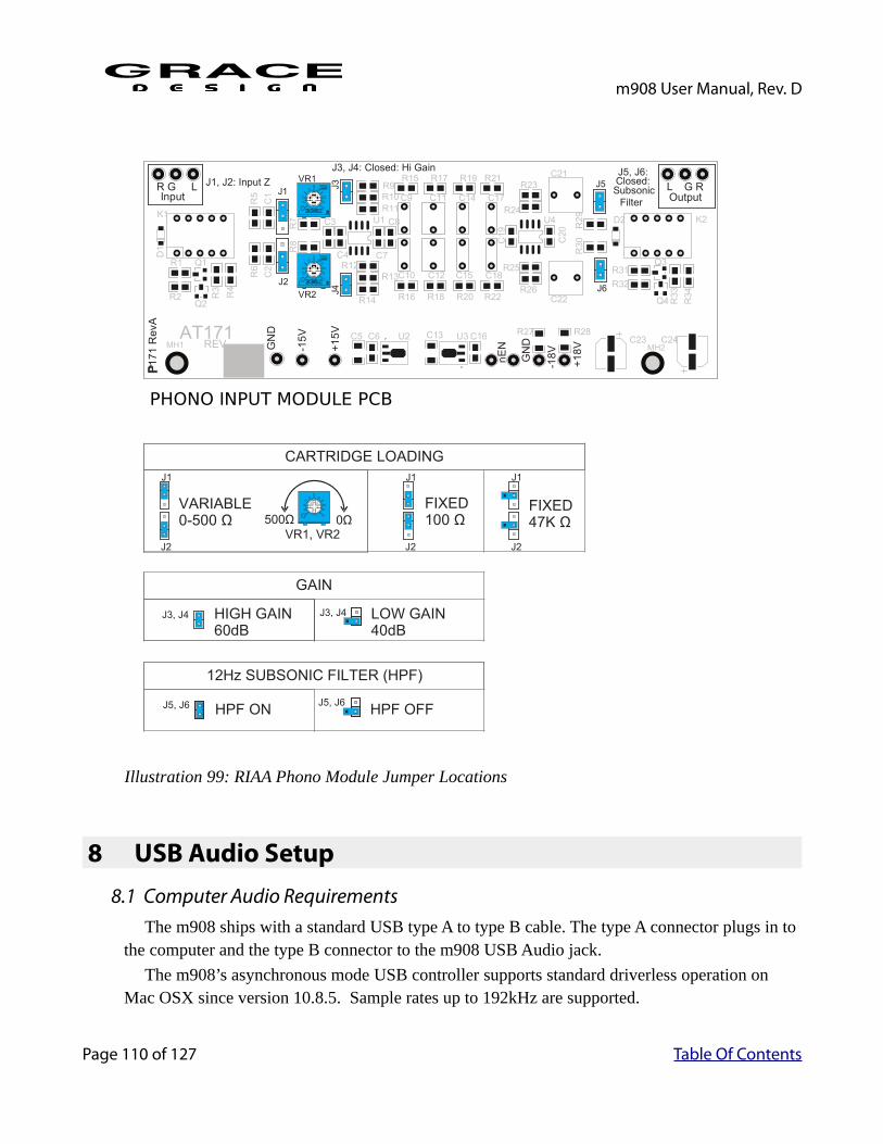
m908 User Manual, Rev. D
8 USm Audio Setup 8.1 Computer Audio Requirements
The m908 ships with a standard USB type A to type B cable. The type A connector plugs in to the computer and the type B connector to the m908 USB Audio jack.
The m908’s asynchronous mode USB controller supports standard driverless operation on Mac OSX since version 10.8.5. Sample rates up to 192kHz are supported.
Page 110 of 127 Table Of Contents
GAIN
J3, J4 HIGH GAIN60dB
J3, J4 LOW GAIN40dB
12Hz SUBSONIC FILTER (HPF)
J5, J6 HPF ON HPF OFFJ5, J6
R14
C6
J3, J4: Closed: Hi Gain
-18
V
+1
8V
R9 R23
C22
U4
J5C21
L G R
U2
R16
R13C10
C13
R18
U3
R20
C12 C15
C7
U1R11R10
C8
C9 C11
C16
nE
N
R22
C18
GN
D
R27
R26
R25
C19
C14 C17R24
R28
R30
J6 R32
R31
C20
R29 D2
C23MH2
Q4
C24
R33
R34
Q3
K2
Output
R15 R17 R19 R21
AT171
R GInput
L J3 J1, J2: Input Z VR1
D1
K1
MH1
R2
R1
Q2
R3
REV GN
D
R4
R6
C2
J2
Q1R
5
R8
C1
R7
J1
-15
VVR2 J4
+1
5V
C4
C5
R12
C3
P1
71
Re
vA
J5, J6:Closed:Subsonic
Filter
CARTRIDGE LOADING
J2
J1
VARIABLE0-500 Ω
FIXED100 Ω
J2
J1
FIXED47K Ω
J2
J1
500Ω 0ΩVR1, VR2
PHONO INPUT MODULE PCB
Illustration 99: RIAA Phono Module Jumper Locations
m908 User Manual, Rev. D
For Windows 7, 8, 8.1, and 10 PC computers, users will need to download and install the Grace Design m908 USB ASIO audio driver. This driver can be found on our website:
http://www.gracedesign.com/support/support.htm
For Windows 7 make sure that your computer has the latest updates from Microsoft or driver installation may fail.
Installation and operation instructions can be found in the following chapter: Windows USB ASIO Driver.
On Mac computers driver-less operation basically means the m908 will automatically show upin your computer’s list of supported audio devices as ‘m908’. The m908 will provide 8 input channels and 24 output channels. In most cases, simply choose the m908 as your audio recording or playback device and the system will work.
In the event that you have any setup issues which aren’t addressed by these resources, feel freeto contact us directly at 303.823.8100, Monday through Friday 9 – 5, MST.
8.2 Windows USB ASIO Driver
8.2.1 Installing USm ADIO Driver
The m908 USB ASIO driver is necessary for operating the m908 as an I/O device on a Windows computer.
1. Connect the m908 to you computer.
2. Download the installer .zip package from our website: http://www.gracedesign.com/support/support.htm Extract the .zip file, and run the installer .exe file.“GraceDesign_TUSBAudio_v4.0.0_2017-04-24_setup.exe”
3. Follow the steps illustrated below (It may take a few moments for the user prompts to appear once the program is running).
4. Depending on the version of Windows your computer is running you may see a security window similar to one of the images shown above. When prompted whether or not you want to allow the program to make changes or if you want to run this file - click “Yes” or “Run” to continue.:
Page 111 of 127 Table Of Contents
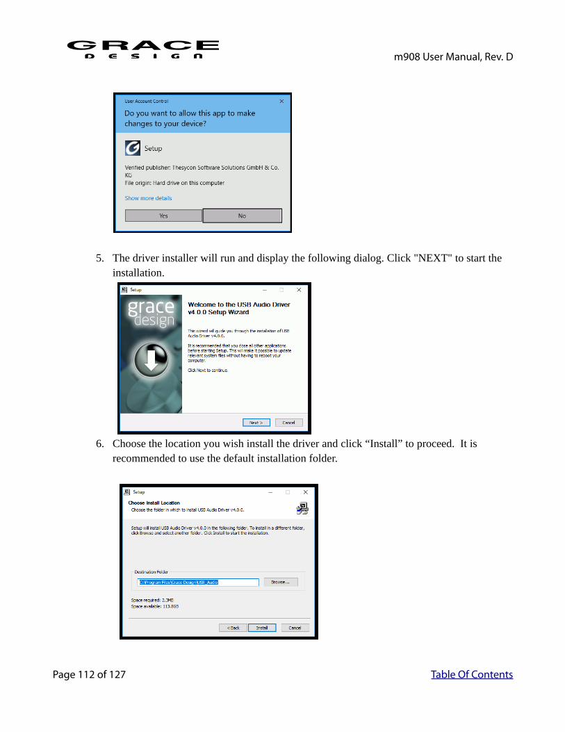
m908 User Manual, Rev. D
5. The driver installer will run and display the following dialog. Click "NEXT" to start the installation.
6. Choose the location you wish install the driver and click “Install” to proceed. It is recommended to use the default installation folder.
Page 112 of 127 Table Of Contents
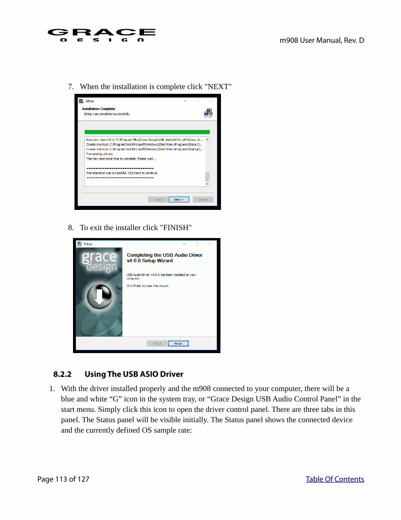
m908 User Manual, Rev. D
7. When the installation is complete click "NEXT"
8. To exit the installer click "FINISH"
8.2.2 Using The USm ASIO Driver
1. With the driver installed properly and the m908 connected to your computer, there will be a blue and white “G” icon in the system tray, or “Grace Design USB Audio Control Panel” in the start menu. Simply click this icon to open the driver control panel. There are three tabs in this panel. The Status panel will be visible initially. The Status panel shows the connected device and the currently defined OS sample rate:
Page 113 of 127 Table Of Contents
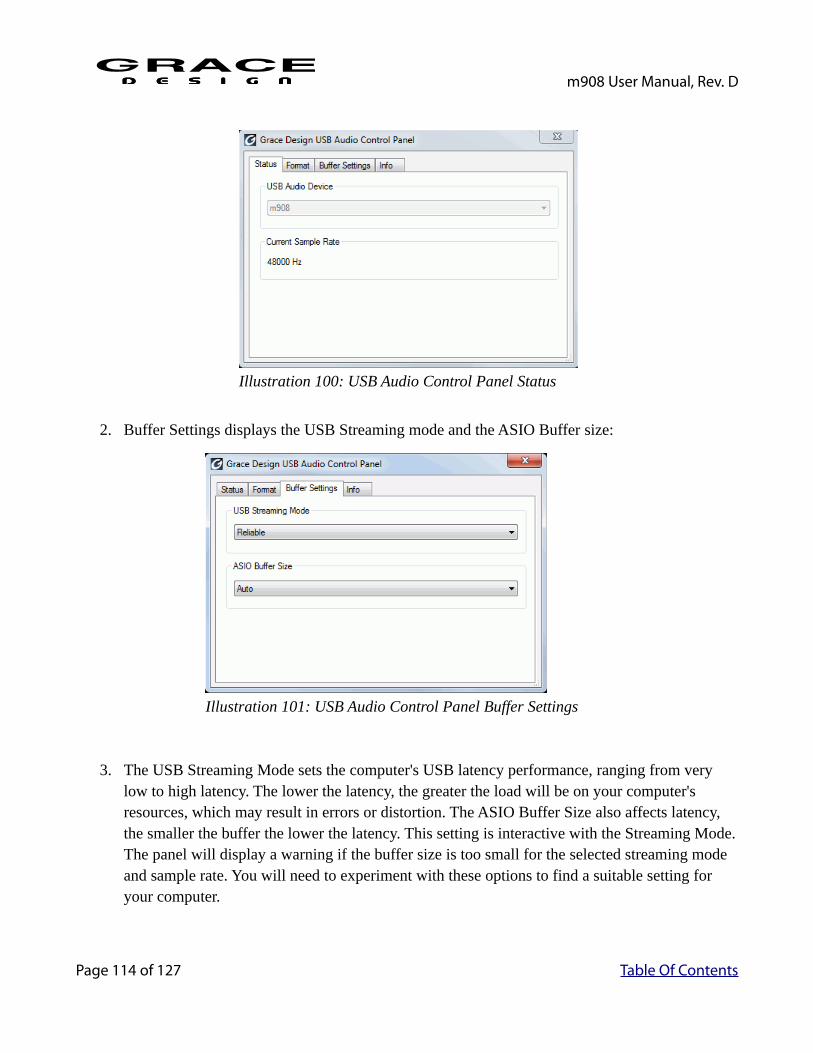
m908 User Manual, Rev. D
2. Buffer Settings displays the USB Streaming mode and the ASIO Buffer size:
3. The USB Streaming Mode sets the computer's USB latency performance, ranging from very low to high latency. The lower the latency, the greater the load will be on your computer's resources, which may result in errors or distortion. The ASIO Buffer Size also affects latency, the smaller the buffer the lower the latency. This setting is interactive with the Streaming Mode.The panel will display a warning if the buffer size is too small for the selected streaming mode and sample rate. You will need to experiment with these options to find a suitable setting for your computer.
Page 114 of 127 Table Of Contents
Illustration 101: USB Audio Control Panel Buffer Settings
Illustration 100: USB Audio Control Panel Status
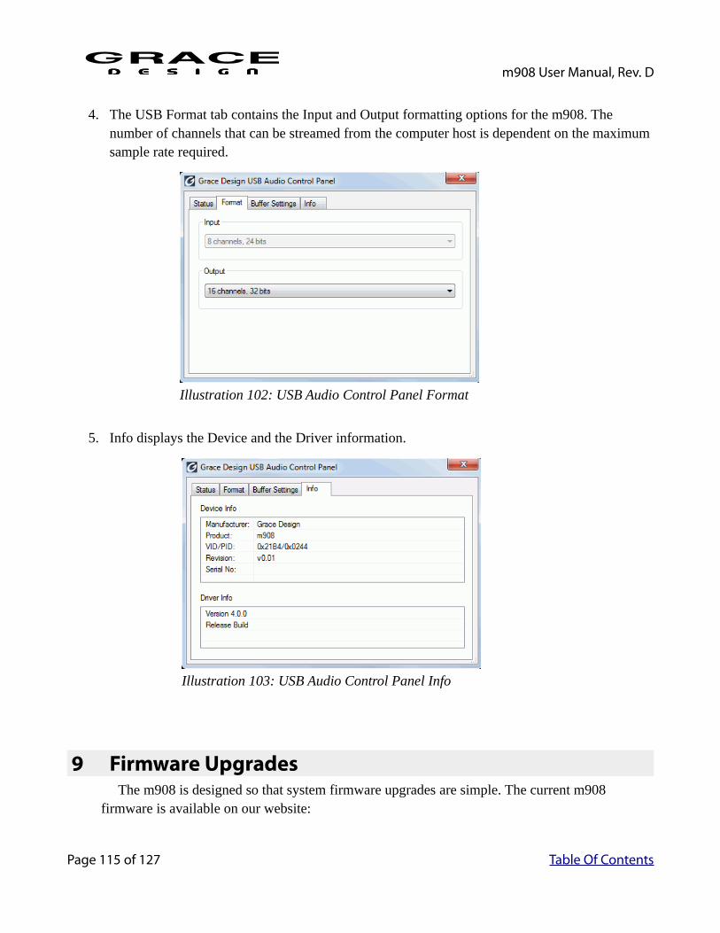
m908 User Manual, Rev. D
4. The USB Format tab contains the Input and Output formatting options for the m908. The number of channels that can be streamed from the computer host is dependent on the maximum sample rate required.
5. Info displays the Device and the Driver information.
9 Firmware UpgradesThe m908 is designed so that system firmware upgrades are simple. The current m908
firmware is available on our website:
Page 115 of 127 Table Of Contents
Illustration 102: USB Audio Control Panel Format
Illustration 103: USB Audio Control Panel Info
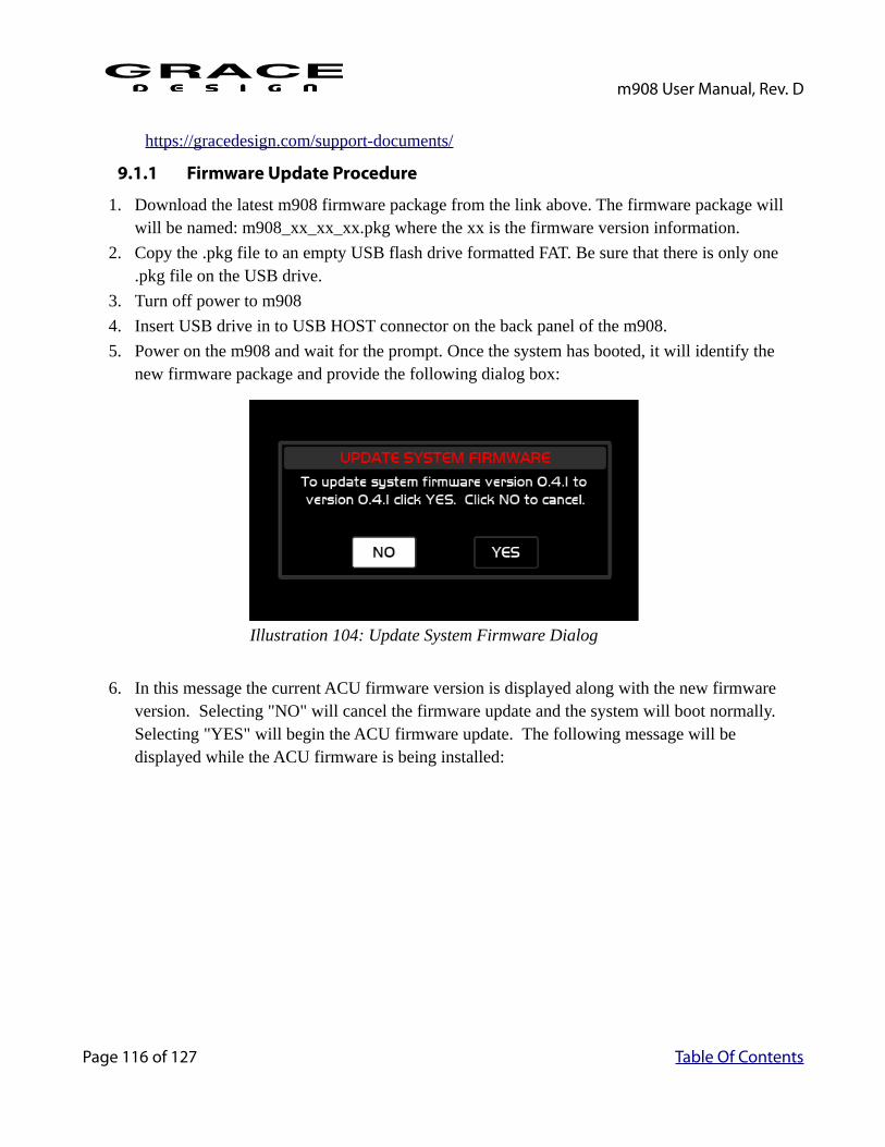
m908 User Manual, Rev. D
https://gracedesign.com/support-documents/
9.1.1 Firmware Update Procedure
1. Download the latest m908 firmware package from the link above. The firmware package will will be named: m908_xx_xx_xx.pkg where the xx is the firmware version information.
2. Copy the .pkg file to an empty USB flash drive formatted FAT. Be sure that there is only one .pkg file on the USB drive.
3. Turn off power to m908
4. Insert USB drive in to USB HOST connector on the back panel of the m908.
5. Power on the m908 and wait for the prompt. Once the system has booted, it will identify the new firmware package and provide the following dialog box:
6. In this message the current ACU firmware version is displayed along with the new firmware version. Selecting "NO" will cancel the firmware update and the system will boot normally. Selecting "YES" will begin the ACU firmware update. The following message will be displayed while the ACU firmware is being installed:
Page 116 of 127 Table Of Contents
Illustration 104: Update System Firmware Dialog
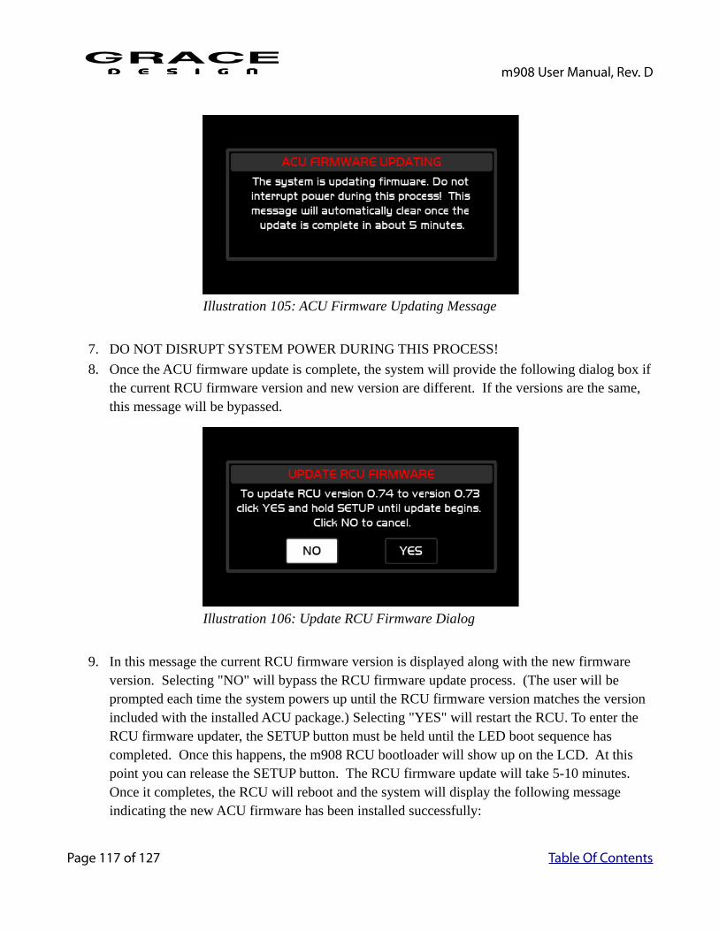
m908 User Manual, Rev. D
7. DO NOT DISRUPT SYSTEM POWER DURING THIS PROCESS!
8. Once the ACU firmware update is complete, the system will provide the following dialog box ifthe current RCU firmware version and new version are different. If the versions are the same, this message will be bypassed.
9. In this message the current RCU firmware version is displayed along with the new firmware version. Selecting "NO" will bypass the RCU firmware update process. (The user will be prompted each time the system powers up until the RCU firmware version matches the version included with the installed ACU package.) Selecting "YES" will restart the RCU. To enter the RCU firmware updater, the SETUP button must be held until the LED boot sequence has completed. Once this happens, the m908 RCU bootloader will show up on the LCD. At this point you can release the SETUP button. The RCU firmware update will take 5-10 minutes. Once it completes, the RCU will reboot and the system will display the following message indicating the new ACU firmware has been installed successfully:
Page 117 of 127 Table Of Contents
Illustration 106: Update RCU Firmware Dialog
Illustration 105: ACU Firmware Updating Message
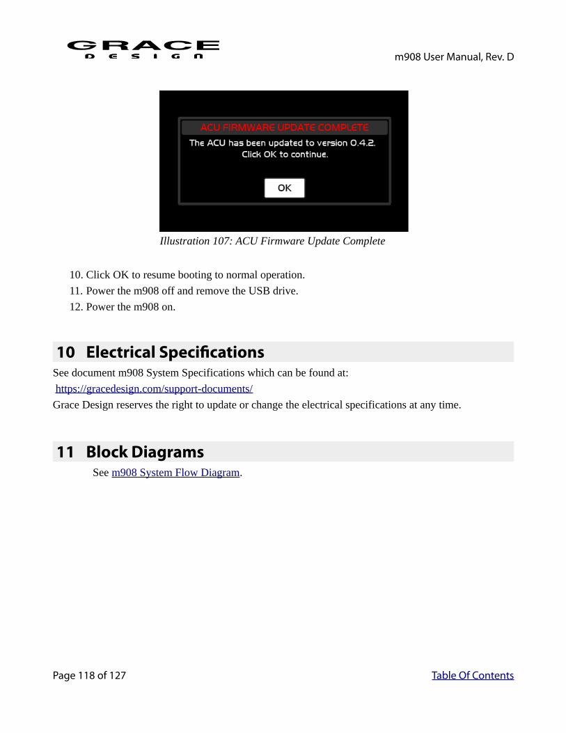
m908 User Manual, Rev. D
10. Click OK to resume booting to normal operation.
11. Power the m908 off and remove the USB drive.
12. Power the m908 on.
10 Electrical SpecifcationsSee document m908 System Specifications which can be found at:
https://gracedesign.com/support-documents/
Grace Design reserves the right to update or change the electrical specifications at any time.
11 mlock DiagramsSee m908 System Flow Diagram.
Page 118 of 127 Table Of Contents
Illustration 107: ACU Firmware Update Complete
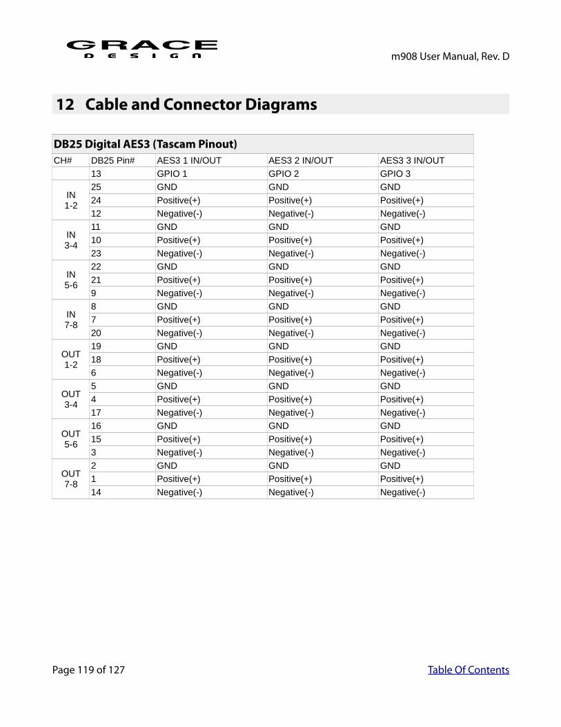
m908 User Manual, Rev. D
12 Cable and Connector Diagrams
Dm25 Digital AES3 (Tascam Pinout)CH# DB25 Pin# AES3 1 IN/OUT AES3 2 IN/OUT AES3 3 IN/OUT
13 GPIO 1 GPIO 2 GPIO 3
IN1-2
25 GND GND GND
24 Positive(+) Positive(+) Positive(+)
12 Negative(-) Negative(-) Negative(-)
IN3-4
11 GND GND GND
10 Positive(+) Positive(+) Positive(+)
23 Negative(-) Negative(-) Negative(-)
IN5-6
22 GND GND GND
21 Positive(+) Positive(+) Positive(+)
9 Negative(-) Negative(-) Negative(-)
IN7-8
8 GND GND GND
7 Positive(+) Positive(+) Positive(+)
20 Negative(-) Negative(-) Negative(-)
OUT1-2
19 GND GND GND
18 Positive(+) Positive(+) Positive(+)
6 Negative(-) Negative(-) Negative(-)
OUT3-4
5 GND GND GND
4 Positive(+) Positive(+) Positive(+)
17 Negative(-) Negative(-) Negative(-)
OUT5-6
16 GND GND GND
15 Positive(+) Positive(+) Positive(+)
3 Negative(-) Negative(-) Negative(-)
OUT7-8
2 GND GND GND
1 Positive(+) Positive(+) Positive(+)
14 Negative(-) Negative(-) Negative(-)
Page 119 of 127 Table Of Contents
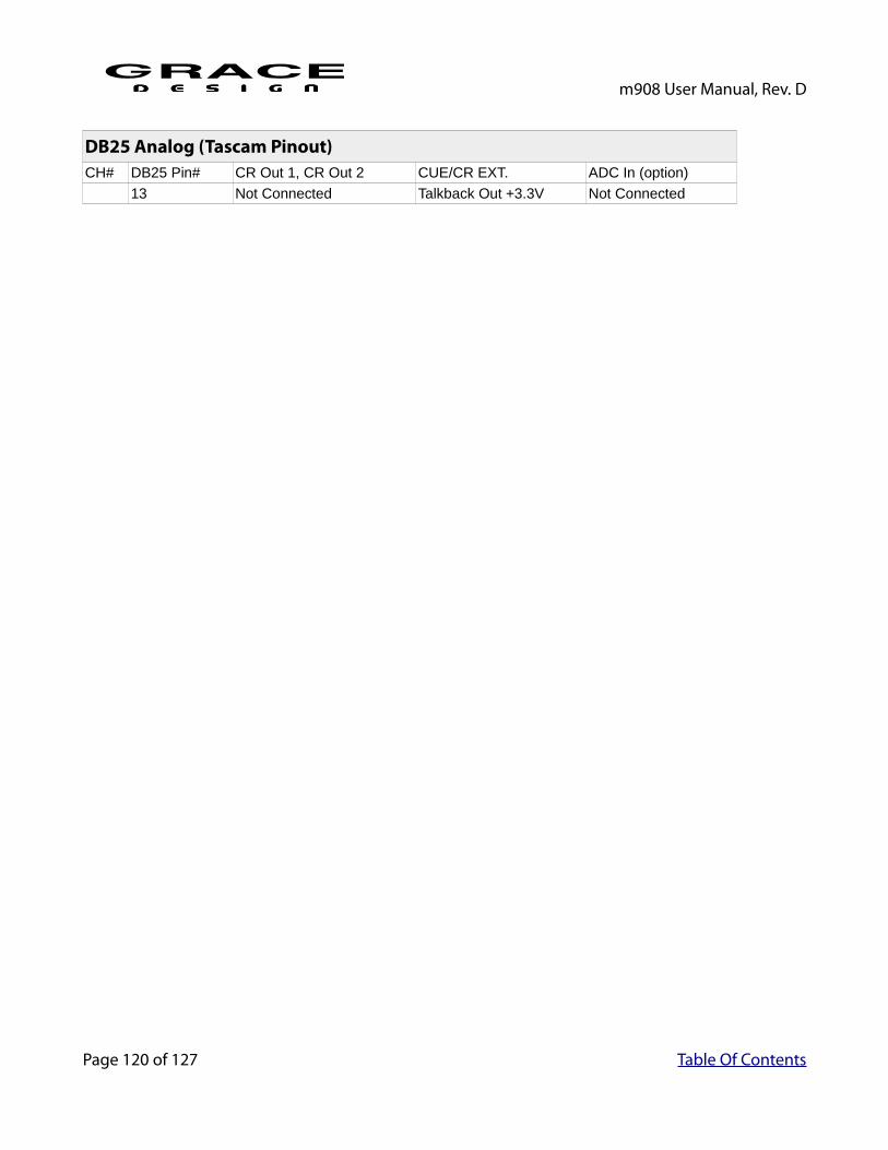
m908 User Manual, Rev. D
Dm25 Analog (Tascam Pinout)CH# DB25 Pin# CR Out 1, CR Out 2 CUE/CR EXT. ADC In (option)
13 Not Connected Talkback Out +3.3V Not Connected
Page 120 of 127 Table Of Contents
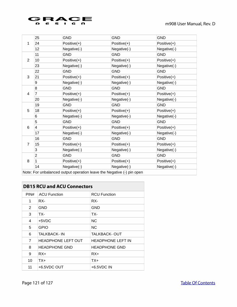
m908 User Manual, Rev. D
1
25 GND GND GND
24 Positive(+) Positive(+) Positive(+)
12 Negative(-) Negative(-) Negative(-)
2
11 GND GND GND
10 Positive(+) Positive(+) Positive(+)
23 Negative(-) Negative(-) Negative(-)
3
22 GND GND GND
21 Positive(+) Positive(+) Positive(+)
9 Negative(-) Negative(-) Negative(-)
4
8 GND GND GND
7 Positive(+) Positive(+) Positive(+)
20 Negative(-) Negative(-) Negative(-)
5
19 GND GND GND
18 Positive(+) Positive(+) Positive(+)
6 Negative(-) Negative(-) Negative(-)
6
5 GND GND GND
4 Positive(+) Positive(+) Positive(+)
17 Negative(-) Negative(-) Negative(-)
7
16 GND GND GND
15 Positive(+) Positive(+) Positive(+)
3 Negative(-) Negative(-) Negative(-)
8
2 GND GND GND
1 Positive(+) Positive(+) Positive(+)
14 Negative(-) Negative(-) Negative(-)
Note: For unbalanced output operation leave the Negative (-) pin open
Dm15 RCU and ACU ConnectorsPIN# ACU Function RCU Function
1 RX- RX-
2 GND GND
3 TX- TX-
4 +5VDC NC
5 GPIO NC
6 TALKBACK- IN TALKBACK- OUT
7 HEADPHONE LEFT OUT HEADPHONE LEFT IN
8 HEADPHONE GND HEADPHONE GND
9 RX+ RX+
10 TX+ TX+
11 +6.5VDC OUT +6.5VDC IN
Page 121 of 127 Table Of Contents
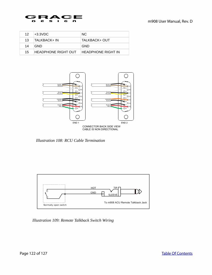
m908 User Manual, Rev. D
12 +3.3VDC NC
13 TALKBACK+ IN TALKBACK+ OUT
14 GND GND
15 HEADPHONE RIGHT OUT HEADPHONE RIGHT IN
Page 122 of 127 Table Of Contents
HOT
GND
TIP
SLEEVE
Normally open switchTo m908 ACU Remote Talkback Jack
Illustration 109: Remote Talkback Switch Wiring
19
210
311
412
513
614
715
8
BLACKORANGE
CONNECTOR BACK SIDE VIEWCABLE IS NON DIRECTIONAL
END 1
BLACK
BLACK
BLACK
BROWN
YELLOW
RED
19
210
311
412
513
614
715
8
BLACKORANGE
BLACK
BLACK
BLACK
BROWN
YELLOW
RED
END 2
Illustration 108: RCU Cable Termination
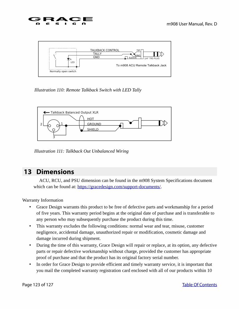
m908 User Manual, Rev. D
13 DimensionsACU, RCU, and PSU dimension can be found in the m908 System Specifications document
which can be found at: https://gracedesign.com/support-documents/.
Warranty Information
• Grace Design warrants this product to be free of defective parts and workmanship for a period of five years. This warranty period begins at the original date of purchase and is transferable to any person who may subsequently purchase the product during this time.
• This warranty excludes the following conditions: normal wear and tear, misuse, customer negligence, accidental damage, unauthorized repair or modification, cosmetic damage and damage incurred during shipment.
• During the time of this warranty, Grace Design will repair or replace, at its option, any defectiveparts or repair defective workmanship without charge, provided the customer has appropriate proof of purchase and that the product has its original factory serial number.
• In order for Grace Design to provide efficient and timely warranty service, it is important that you mail the completed warranty registration card enclosed with all of our products within 10
Page 123 of 127 Table Of Contents
TALLYTALKBACK CONTROL
GND 1/4" TRS PLUG
TIP
SLEEVE
LED
Normally open switch
To m908 ACU Remote Talkback Jack
RING
Illustration 110: Remote Talkback Switch with LED Tally
12
3
SHIELD
HOT
GROUND
Talkback Balanced Output XLR
Illustration 111: Talkback Out Unbalanced Wiring
m908 User Manual, Rev. D
days of the original date of purchase. You may also register your product directly with Grace Design by telephone (303-823-8100 Monday-Friday 9:00am to 5:00pm MST), or you can register your product online at www.gracedesign.com.
• This warranty is in lieu of all other warranties whether written, expressed, or implied, INCLUDING ANY WARRANTIES OF MERCHANTABILITY OR FITNESS FOR A PARTICULAR PURPOSE.
• In no event will Grace Design be liable for lost profits or any other incidental, consequential or Exemplary damages, even if Grace Design is aware of the possibility of such damages. In no event will Grace Design’s liability exceed the purchase price of the product.
• This warranty gives the customer specific legal rights. The customer may also have other rights,which vary from state to state. Some states do not allow limitations on implied warranties or consequential damages, so some of the limitations of the above may not apply to a particular customer.
Page 124 of 127 Table Of Contents
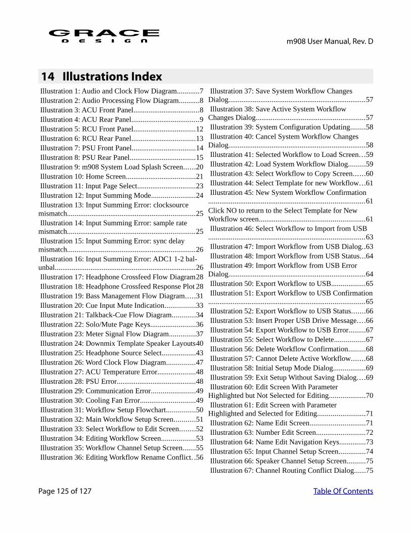
m908 User Manual, Rev. D
14 Illustrations Index Illustration 1: Audio and Clock Flow Diagram............7 Illustration 2: Audio Processing Flow Diagram...........8 Illustration 3: ACU Front Panel...................................8 Illustration 4: ACU Rear Panel....................................9 Illustration 5: RCU Front Panel.................................12 Illustration 6: RCU Rear Panel..................................13 Illustration 7: PSU Front Panel..................................14 Illustration 8: PSU Rear Panel...................................15 Illustration 9: m908 System Load Splash Screen......20 Illustration 10: Home Screen.....................................21 Illustration 11: Input Page Select...............................23 Illustration 12: Input Summing Mode.......................24 Illustration 13: Input Summing Error: clocksource mismatch....................................................................25 Illustration 14: Input Summing Error: sample rate mismatch....................................................................25 Illustration 15: Input Summing Error: sync delay mismatch....................................................................26 Illustration 16: Input Summing Error: ADC1 1-2 bal-unbal...........................................................................26 Illustration 17: Headphone Crossfeed Flow Diagram28 Illustration 18: Headphone Crossfeed Response Plot 28 Illustration 19: Bass Management Flow Diagram.....31 Illustration 20: Cue Input Mute Indication................33 Illustration 21: Talkback-Cue Flow Diagram............34 Illustration 22: Solo/Mute Page Keys........................36 Illustration 23: Meter Signal Flow Diagram..............37 Illustration 24: Downmix Template Speaker Layouts40 Illustration 25: Headphone Source Select..................43 Illustration 26: Word Clock Flow Diagram...............47 Illustration 27: ACU Temperature Error....................48 Illustration 28: PSU Error..........................................48 Illustration 29: Communication Error.......................49 Illustration 30: Cooling Fan Error.............................49 Illustration 31: Workflow Setup Flowchart...............50 Illustration 32: Main Workflow Setup Screen...........51 Illustration 33: Select Workflow to Edit Screen........52 Illustration 34: Editing Workflow Screen..................53 Illustration 35: Workflow Channel Setup Screen.......55 Illustration 36: Editing Workflow Rename Conflict. .56
Illustration 37: Save System Workflow Changes Dialog.........................................................................57 Illustration 38: Save Active System Workflow Changes Dialog..........................................................57 Illustration 39: System Configuration Updating........58 Illustration 40: Cancel System Workflow Changes Dialog.........................................................................58 Illustration 41: Selected Workflow to Load Screen. . .59 Illustration 42: Load System Workflow Dialog.........59 Illustration 43: Select Workflow to Copy Screen......60 Illustration 44: Select Template for new Workflow...61 Illustration 45: New System Workflow Confirmation...................................................................................61Click NO to return to the Select Template for New Workflow screen........................................................61 Illustration 46: Select Workflow to Import from USB...................................................................................63 Illustration 47: Import Workflow from USB Dialog..63 Illustration 48: Import Workflow from USB Status...64 Illustration 49: Import Workflow from USB Error Dialog.........................................................................64 Illustration 50: Export Workflow to USB..................65 Illustration 51: Export Workflow to USB Confirmation...................................................................................65 Illustration 52: Export Workflow to USB Status.......66 Illustration 53: Insert Proper USB Drive Message....66 Illustration 54: Export Workflow to USB Error.........67 Illustration 55: Select Workflow to Delete................67 Illustration 56: Delete Workflow Confirmation.........68 Illustration 57: Cannot Delete Active Workflow.......68 Illustration 58: Initial Setup Mode Dialog.................69 Illustration 59: Exit Setup Without Saving Dialog....69 Illustration 60: Edit Screen With Parameter Highlighted but Not Selected for Editing...................70 Illustration 61: Edit Screen with Parameter Highlighted and Selected for Editing.........................71 Illustration 62: Name Edit Screen.............................71 Illustration 63: Number Edit Screen..........................72 Illustration 64: Name Edit Navigation Keys..............73 Illustration 65: Input Channel Setup Screen..............74 Illustration 66: Speaker Channel Setup Screen..........75 Illustration 67: Channel Routing Conflict Dialog......75
Page 125 of 127 Table Of Contents
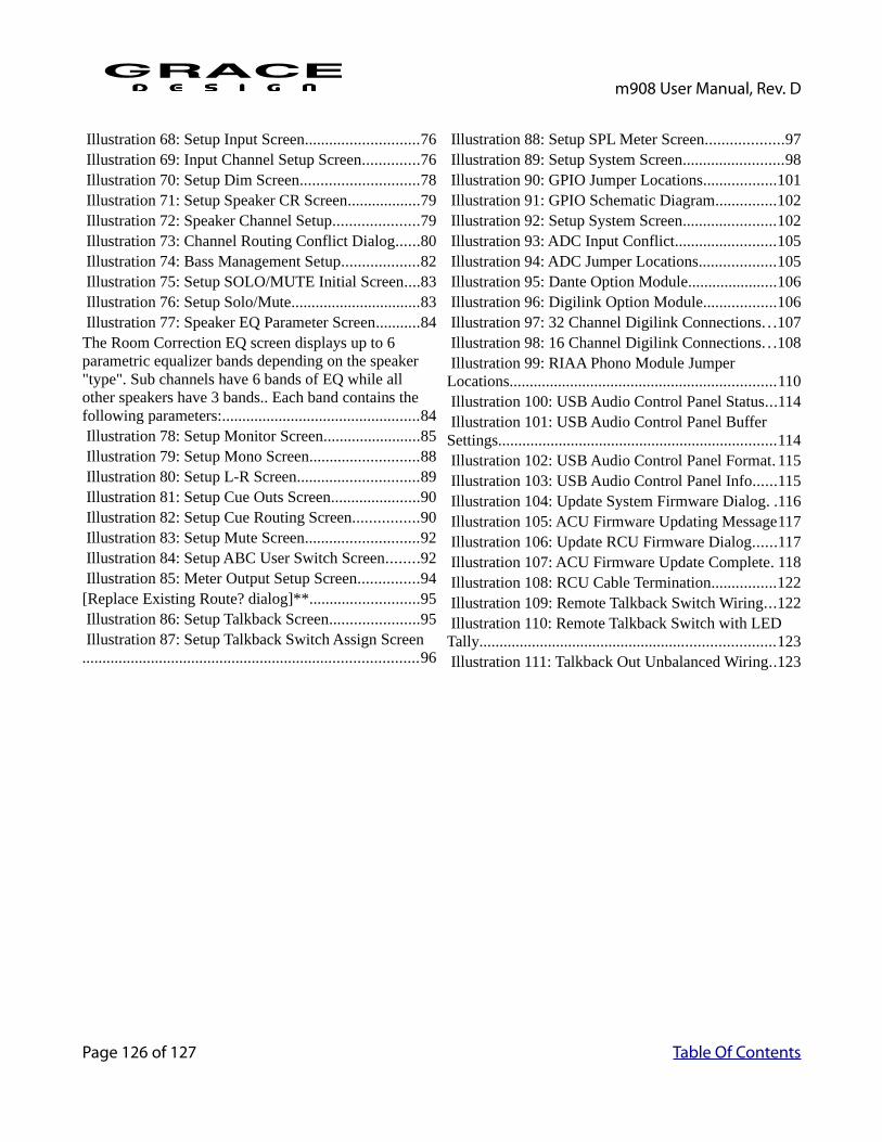
m908 User Manual, Rev. D
Illustration 68: Setup Input Screen............................76 Illustration 69: Input Channel Setup Screen..............76 Illustration 70: Setup Dim Screen.............................78 Illustration 71: Setup Speaker CR Screen..................79 Illustration 72: Speaker Channel Setup.....................79 Illustration 73: Channel Routing Conflict Dialog......80 Illustration 74: Bass Management Setup...................82 Illustration 75: Setup SOLO/MUTE Initial Screen....83 Illustration 76: Setup Solo/Mute................................83 Illustration 77: Speaker EQ Parameter Screen...........84The Room Correction EQ screen displays up to 6 parametric equalizer bands depending on the speaker "type". Sub channels have 6 bands of EQ while all other speakers have 3 bands.. Each band contains the following parameters:.................................................84 Illustration 78: Setup Monitor Screen........................85 Illustration 79: Setup Mono Screen...........................88 Illustration 80: Setup L-R Screen..............................89 Illustration 81: Setup Cue Outs Screen......................90 Illustration 82: Setup Cue Routing Screen................90 Illustration 83: Setup Mute Screen............................92 Illustration 84: Setup ABC User Switch Screen........92 Illustration 85: Meter Output Setup Screen...............94[Replace Existing Route? dialog]**...........................95 Illustration 86: Setup Talkback Screen......................95 Illustration 87: Setup Talkback Switch Assign Screen...................................................................................96
Illustration 88: Setup SPL Meter Screen...................97 Illustration 89: Setup System Screen.........................98 Illustration 90: GPIO Jumper Locations..................101 Illustration 91: GPIO Schematic Diagram...............102 Illustration 92: Setup System Screen.......................102 Illustration 93: ADC Input Conflict.........................105 Illustration 94: ADC Jumper Locations...................105 Illustration 95: Dante Option Module......................106 Illustration 96: Digilink Option Module..................106 Illustration 97: 32 Channel Digilink Connections. . .107 Illustration 98: 16 Channel Digilink Connections. . .108 Illustration 99: RIAA Phono Module Jumper Locations..................................................................110 Illustration 100: USB Audio Control Panel Status...114 Illustration 101: USB Audio Control Panel Buffer Settings.....................................................................114 Illustration 102: USB Audio Control Panel Format. 115 Illustration 103: USB Audio Control Panel Info......115 Illustration 104: Update System Firmware Dialog. .116 Illustration 105: ACU Firmware Updating Message117 Illustration 106: Update RCU Firmware Dialog......117 Illustration 107: ACU Firmware Update Complete. 118 Illustration 108: RCU Cable Termination................122 Illustration 109: Remote Talkback Switch Wiring...122 Illustration 110: Remote Talkback Switch with LED Tally.........................................................................123 Illustration 111: Talkback Out Unbalanced Wiring..123
Page 126 of 127 Table Of Contents
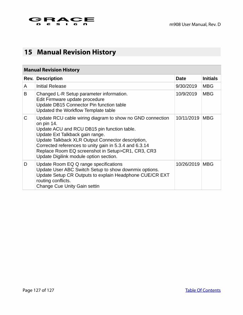
m908 User Manual, Rev. D
15 Manual Revision History
Manual Revision History
Rev. Description Date Initials
A Initial Release 9/30/2019 MBG
B Changed L-R Setup parameter information.Edit Firmware update procedureUpdate DB15 Connector Pin function tableUpdated the Workflow Template table
10/9/2019 MBG
C Update RCU cable wiring diagram to show no GND connection on pin 14.Update ACU and RCU DB15 pin function table.Update Ext Talkback gain range.Update Talkback XLR Output Connector description,Corrected references to unity gain in 5.3.4 and 6.3.14Replace Room EQ screenshot in Setup>CR1, CR3, CR3Update Digilink module option section.
10/11/2019 MBG
D Update Room EQ Q range specificationsUpdate User ABC Switch Setup to show downmix options.Update Setup CR Outputs to explain Headphone CUE/CR EXT routing conflicts.Change Cue Unity Gain settin
10/26/2019 MBG
Page 127 of 127 Table Of Contents