Embed Size (px)
DESCRIPTION
SsangYong automatic transmission
Citation preview
Contents
1. M78 Auto T/M 2. Appendix I
- CDPF- Locking Differential
3. Appendix II- Trouble shooting- S/Bulletin (2006~2008)- T/Information (2006~2008)

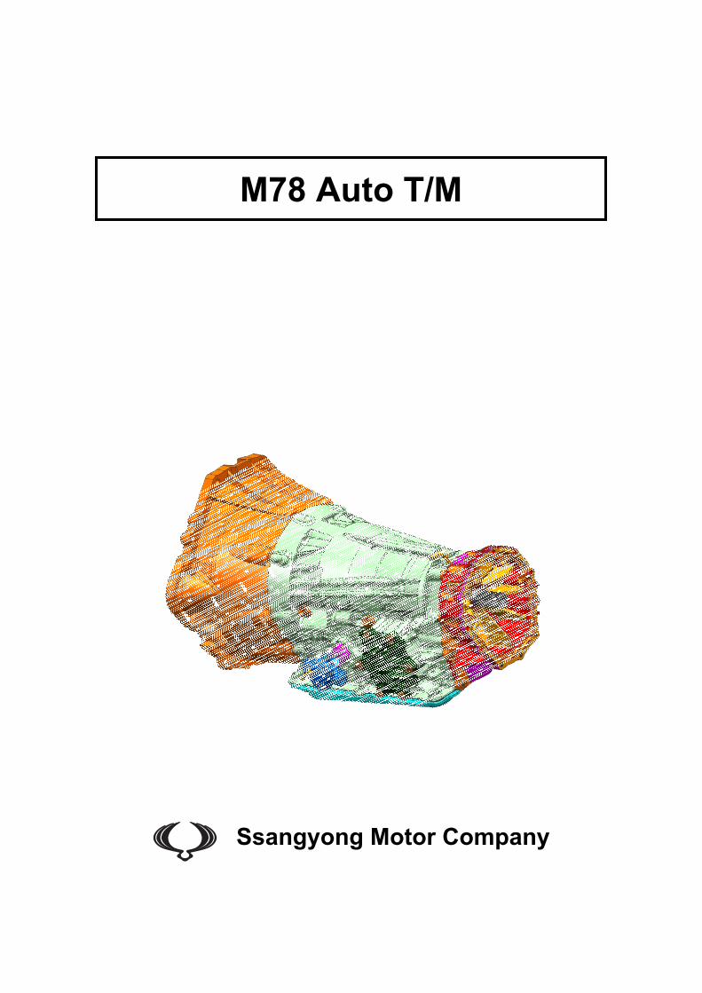
M78 Auto T/M
Ssangyong Motor Company
M78 Automatic Transmission Page–2
Ssangyong Motor Company
Table of Contents M78 Automatic transmission ..........................................................................................................................1
1 System Operation...................................................................................................................................4 1.1 General Description............................................................................................................................................... 4 1.2 Advanced Six Speed Features.............................................................................................................................. 5
Early Downshifts with Hard Braking and Skip Shifts ......................................................................................... 5 Gear Hold Going Uphill/Downhill.......................................................................................................................... 5 Upshift Prevention with Fast-off Accelerator Pedal............................................................................................ 5 Drive and Reverse Engagement ........................................................................................................................... 5 Converter Clutch Lock-Up In All Gears................................................................................................................ 5 Embedded Memory Module .................................................................................................................................. 5
1.3 Transmission Cooling ........................................................................................................................................... 6 1.4 Shift Strategy.......................................................................................................................................................... 6
Gear Change........................................................................................................................................................... 6 Coastdown.............................................................................................................................................................. 6 Torque Demand...................................................................................................................................................... 6 Range Mode (Manual Mode).................................................................................................................................. 6
1st Gear State ..........................................................................................................................................................................6 2nd Gear State .........................................................................................................................................................................6 3rd Gear State..........................................................................................................................................................................6 4th Gear State ..........................................................................................................................................................................6 5th Gear State ..........................................................................................................................................................................6 6th Gear State ..........................................................................................................................................................................6
1.5 Transmission Components................................................................................................................................... 7 Gear Train............................................................................................................................................................... 7 Single Planetary Gear-set ..................................................................................................................................... 8 Double Planetary.................................................................................................................................................... 8 Clutches and Brake Bands.................................................................................................................................... 9 Torque Converter................................................................................................................................................... 9 Torque Converter Lock-up Clutch...................................................................................................................... 10 Fluid Pump ........................................................................................................................................................... 11
1.6 Hydraulic Schematics.......................................................................................................................................... 12 Overall Hydraulic Circuit ..................................................................................................................................... 12 Gear Fluid Flow Schematics ............................................................................................................................... 14
1st Gear Power Path — Ratio 3.53:1.....................................................................................................................................14 Manual 1st Gear Power Path — Ratio 3.53:1 ........................................................................................................................14 2nd Gear Power Path — Ratio 2.14:1 ....................................................................................................................................14 3rd Gear Power Path — Ratio 1.48:1.....................................................................................................................................15 4th Gear Power Path — Ratio 1.16:1.....................................................................................................................................15 5th Gear Power Path — Ratio 0.87:1.....................................................................................................................................15 6th Gear Power Path — Ratio 0.68:1.....................................................................................................................................16 Reverse Gear Power Path — Ratio 3.09:1 ...........................................................................................................................16 Neutral...................................................................................................................................................................................16 Park.......................................................................................................................................................................................17
1.7 Transmission Electronic Control System.......................................................................................................... 17 Transmission Control Unit .................................................................................................................................. 17 Communication Network..................................................................................................................................... 18 Embedded Memory Module ................................................................................................................................ 18 Solenoid Valves and Variable Bleed Solenoids ................................................................................................ 19 Sensor Inputs....................................................................................................................................................... 20
Brake Pedal Position Switch .................................................................................................................................................20 Engine Intake Temperature Sensor ......................................................................................................................................20 Barometric Pressure Sensor .................................................................................................................................................20 Accelerator Pedal Position Sensor........................................................................................................................................20 Input Shaft Speed Sensor .....................................................................................................................................................20 Output Shaft Speed Sensor ..................................................................................................................................................20 Transmission Fluid Temperature Sensor ..............................................................................................................................21 Inhibitor Switch......................................................................................................................................................................21
Transmission Control Monitoring System......................................................................................................... 21 Supply Monitoring .................................................................................................................................................................21
M78 Automatic Transmission Page–3
Ssangyong Motor Company
Solenoid Supply Monitoring ..................................................................................................................................................21 Gear Ratio Monitoring ...........................................................................................................................................................21 Torque Converter Monitoring ................................................................................................................................................22
Shift Energy Management ................................................................................................................................... 22 Pressure Modulation .............................................................................................................................................................22
Shift Map Selection.............................................................................................................................................. 22 Normal Mode.........................................................................................................................................................................22 Uphill and Downhill Mode......................................................................................................................................................22 Altitude Mode ........................................................................................................................................................................22 Winter Mode..........................................................................................................................................................................22 Low Range Schedule ............................................................................................................................................................22 Warm up Schedule................................................................................................................................................................22 Hot Mode...............................................................................................................................................................................23 Cruise....................................................................................................................................................................................23
2 Diagnosis and Testing .........................................................................................................................24 2.1 Wiring Diagram .................................................................................................................................................... 24 2.2 Wire Harness Connector Chart........................................................................................................................... 25 2.3 Unit Connector Description ................................................................................................................................ 25
Transmission Control Unit .................................................................................................................................. 25 Connector J1.........................................................................................................................................................................25 Connector J2.........................................................................................................................................................................25 Connector J3.........................................................................................................................................................................25
Transmission........................................................................................................................................................ 26 Connector J4.........................................................................................................................................................................26
Inhibitor Switch .................................................................................................................................................... 26 Connector J5.........................................................................................................................................................................26
2.4 Trouble Code Diagnosis...................................................................................................................................... 27 Diagnostic Trouble Code List ............................................................................................................................. 27 Sub-System .......................................................................................................................................................... 29
TCU.......................................................................................................................................................................................29 Inhibitor Switch Assembly .....................................................................................................................................................31 Transmission Cooling............................................................................................................................................................33 Transmission Oil Temperature Sensor .................................................................................................................................34 Input Speed Sensor ..............................................................................................................................................................37 Transmission Gear Select Lever...........................................................................................................................................41 Output Speed Sensor............................................................................................................................................................44 Gear Engagement.................................................................................................................................................................47 Torque Converter Control .....................................................................................................................................................49 Steering Wheel......................................................................................................................................................................50 Variable Bleed Solenoids ......................................................................................................................................................53 On/Off Solenoids...................................................................................................................................................................60 CAN Network ........................................................................................................................................................................64 TCU Calibration.....................................................................................................................................................................66
3 Maintenance Operations......................................................................................................................68 3.1 Stall Test............................................................................................................................................................... 68 3.2 Transmission Reset Procedure (Replacement Transmission) ........................................................................ 68
Green Offset Reset .............................................................................................................................................. 68 Adaptive Reset ..................................................................................................................................................... 68 Green Offset Reset Procedure............................................................................................................................ 68 Adaptive Reset Procedure .................................................................................................................................. 68
3.3 Fluid Level Inspection ......................................................................................................................................... 69 3.4 Transmission Cooler and Hydraulic Line Flushing Procedure (New Transmission)..................................... 70
4 Lubrication............................................................................................................................................71
5 Torque Specifications..........................................................................................................................72
M78 Automatic Transmission Page–4
Ssangyong Motor Company
1 System Operation
1.1 General Description
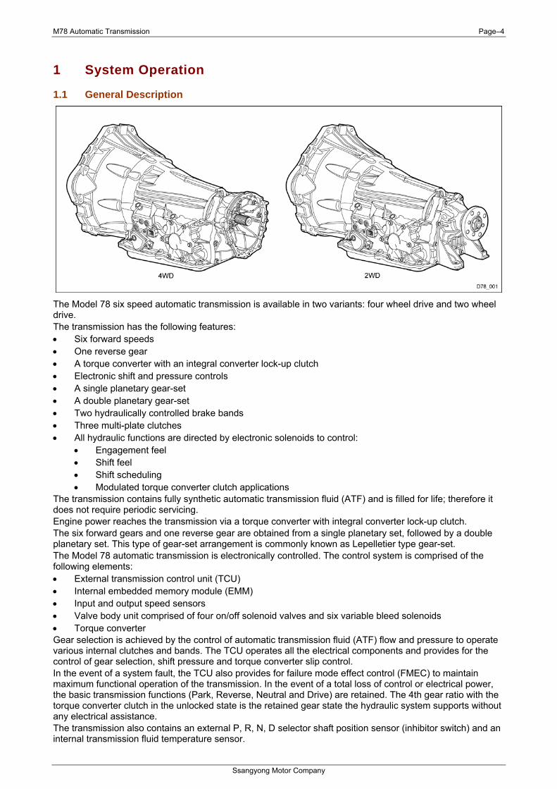
The Model 78 six speed automatic transmission is available in two variants: four wheel drive and two wheel drive. The transmission has the following features: • Six forward speeds • One reverse gear • A torque converter with an integral converter lock-up clutch • Electronic shift and pressure controls • A single planetary gear-set • A double planetary gear-set • Two hydraulically controlled brake bands • Three multi-plate clutches • All hydraulic functions are directed by electronic solenoids to control:
• Engagement feel • Shift feel • Shift scheduling • Modulated torque converter clutch applications
The transmission contains fully synthetic automatic transmission fluid (ATF) and is filled for life; therefore it does not require periodic servicing. Engine power reaches the transmission via a torque converter with integral converter lock-up clutch. The six forward gears and one reverse gear are obtained from a single planetary set, followed by a double planetary set. This type of gear-set arrangement is commonly known as Lepelletier type gear-set. The Model 78 automatic transmission is electronically controlled. The control system is comprised of the following elements: • External transmission control unit (TCU) • Internal embedded memory module (EMM) • Input and output speed sensors • Valve body unit comprised of four on/off solenoid valves and six variable bleed solenoids • Torque converter Gear selection is achieved by the control of automatic transmission fluid (ATF) flow and pressure to operate various internal clutches and bands. The TCU operates all the electrical components and provides for the control of gear selection, shift pressure and torque converter slip control. In the event of a system fault, the TCU also provides for failure mode effect control (FMEC) to maintain maximum functional operation of the transmission. In the event of a total loss of control or electrical power, the basic transmission functions (Park, Reverse, Neutral and Drive) are retained. The 4th gear ratio with the torque converter clutch in the unlocked state is the retained gear state the hydraulic system supports without any electrical assistance. The transmission also contains an external P, R, N, D selector shaft position sensor (inhibitor switch) and an internal transmission fluid temperature sensor.
M78 Automatic Transmission Page–5
Ssangyong Motor Company
With manual mode applications, the TCU also requires information from the transmission gear selector (TGS) shift knob to determine when the driver has initiated a manual gear selection. The TCU communicates with other vehicle electronic control modules by the controller area network (CAN). If a major fault develops, the transmission may automatically operate in a “limp home” (failure) mode to enable the vehicle to be driven to an authorised dealer for repair. During “limp home” mode, the MIL indicator on instrument cluster will be set and the transmission will operate with limited functionality. The level of functionality is dependant on the fault detected. When in limp home mode, the transmission indicator light on the instrument cluster will flash. Limp home mode may also be engaged if the battery charge falls below 8V. If the transmission overheats, the shift patterns will automatically change to enable improved transmission cooling. During transmission overheat, the instrument cluster transmission selector position display and the over temperature condition is indicated by flashing the “WINTER” indicator on the instrument cluster until normal transmission operating temperature is reached. Under extreme over-temperature conditions, the transmission will disable all shifting and remain in a neutral state until it has cooled to a safe level. The TCU also provides for transmission diagnostics, which meet the requirements of OBD II legislation, monitoring all components which may effect vehicle emissions. Additional diagnostic functions are also supported to ensure fast repairs of all failures in the service environment. In the event of a vehicle breakdown, the vehicle can be towed, providing the main driveshaft has been removed prior to towing. Failure to do this will lead to a failed transmission due to insufficient lubrication to transmission bearings.
1.2 Advanced Six Speed Features
Early Downshifts with Hard Braking and Skip Shifts When heavy braking is detected, the transmission downshifts early and skips gears to provide increased engine braking to provide gear selection for tip-in.
Gear Hold Going Uphill/Downhill If the accelerator pedal is released when travelling uphill, upshifts are prevented to reduce busyness on grades. If the accelerator pedal is released when travelling downhill, upshifts are prevented to enhance engine braking.
Upshift Prevention with Fast-off Accelerator Pedal Upshifts are prevented when the throttle is backed off very quickly to reduce busyness in sporty driving.
Drive and Reverse Engagement A soft engagement feature avoids harsh take up of drive when selecting Drive or Reverse. This is achieved by limiting engine speed and engine torque which results in a rapid, but progressive engagement of either Drive or Reverse when moving from the Park or Neutral positions. Drive and Reverse engagements from either Park or Neutral are performed in less than 2.2 seconds. There is no drive engagement prevention strategy implemented on the transmission system as there is sufficient engine strategy to protect the system. However, reverse engagement is prevented until engine speed is less than 1400 rpm and the accelerator pedal position is less than 12% and vehicle speed is less than 10 km/h.
Converter Clutch Lock-Up In All Gears The transmission features converter clutch lock-up in all gears. This feature provides improved fuel economy and vehicle performance. It also improves transmission cooling efficiency when towing heavy loads at low speeds, e.g. in city driving or hill terrain.
Embedded Memory Module The embedded memory module (EMM) is matched to the transmission’s valve bodies during transmission assembly to ensure refined shift quality. The EMM is integrated into the input speed sensor which is mounted on the valve body in the transmission. The EMM is used to store data such as valve body calibration data and valve body serial number. Upon installation, the TCU will download the data from the EMM and utilise this data in the operation of the transmission.
M78 Automatic Transmission Page–6
Ssangyong Motor Company
1.3 Transmission Cooling The transmission cooling system ensures rapid warm-up and constant operating temperature resulting in reduced fuel consumption and refined shift quality. It also includes a cooler by-pass within the hydraulic system to allow sufficient cooling and lubrication to the transmission drivetrain in the event of a blockage in the transmission cooler.
1.4 Shift Strategy
Gear Change Transmission gear change is controlled by the TCU. The TCU receives inputs from various engine and vehicle sensors to select shift schedules and to control the shift feel and torque converter clutch (TCC) operation at each gear change.
Coastdown Coastdown downshifts occur at 0% pedal when the vehicle is coasting down to a stop.
Torque Demand Torque demand downshifts occur (automatically) when the driver demand for torque is greater than the engine can provide at that gear ratio. If applied, the transmission will disengage the TCC to provide added acceleration.
Range Mode (Manual Mode) This allows the driver to define the highest possible gear by selecting “+” or “–” on the gear selector when the lever is in the “M” position. When the lever is first moved to the manual “M” position the transmission will select the lowest possible gear. When maximum engine rpm is reached the transmission will upshift automatically regardless of the driver selected limit. 4WD models with low range will not automatically upshift when low range is selected.
1st Gear State The 1st gear state will display on the instrument cluster. Unlike the normal 1st gear, engine braking will be available in this manual 1st state.
2nd Gear State The 2nd gear state will display on the instrument cluster. 2–1 automatic kick-down shifts are available. 2nd gear has engine braking available.
3rd Gear State The 3rd gear state will display on the instrument cluster. 3–2 and 3–1 automatic kick-down shifts are available. 3rd gear has engine braking available.
4th Gear State The 4th gear state will display on the instrument cluster. 4–3, 4–2 and 4–1 automatic kick-down shifts are available. 4th gear has engine braking available.
5th Gear State The 5th gear state will display on the instrument cluster. 5–4, 5–3 automatic kick-down shifts are available. 5th gear has engine braking available.
6th Gear State The 6th gear state will display on the instrument cluster. 6–5, 6–4 automatic kick-down shifts are available. 6th gear has engine braking available.
M78 Automatic Transmission Page–7
Ssangyong Motor Company
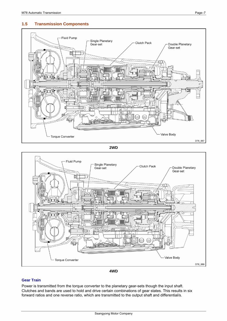
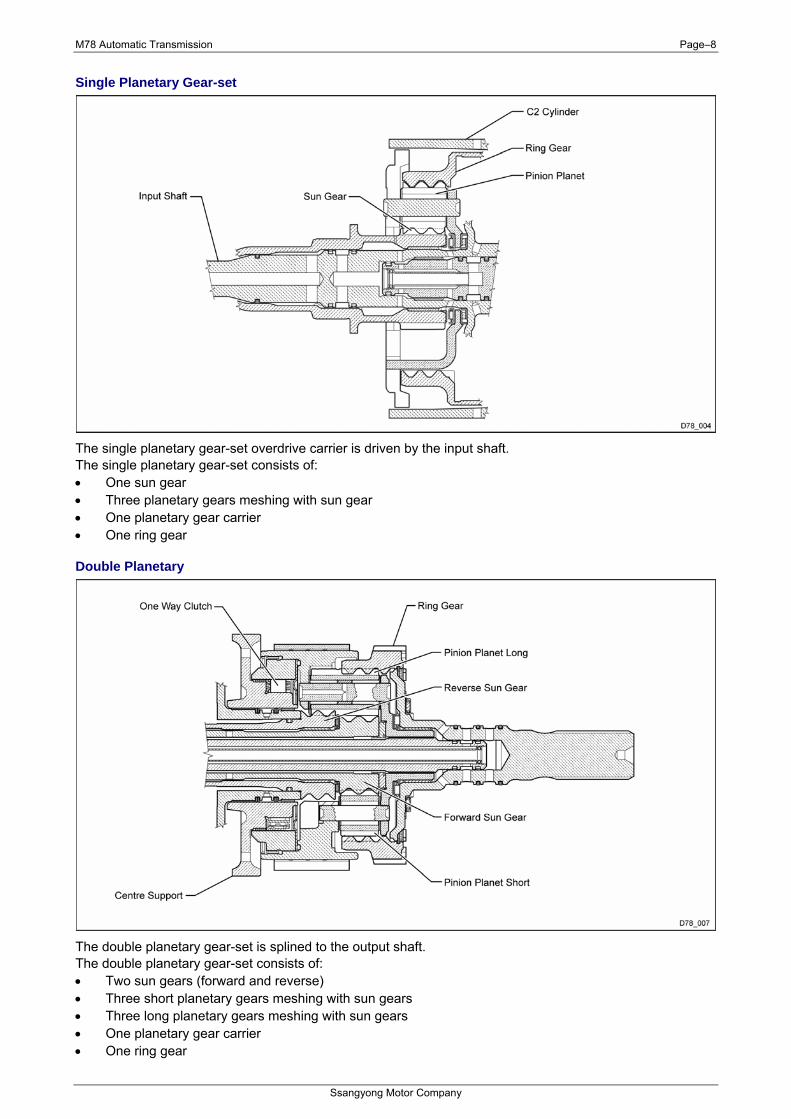
1.5 Transmission Components
2WD
4WD
Gear Train Power is transmitted from the torque converter to the planetary gear-sets though the input shaft. Clutches and bands are used to hold and drive certain combinations of gear states. This results in six forward ratios and one reverse ratio, which are transmitted to the output shaft and differential/s.
M78 Automatic Transmission Page–8
Ssangyong Motor Company
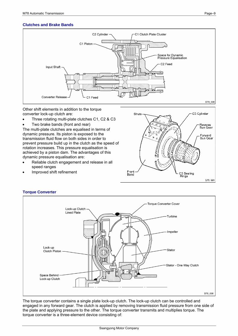
Single Planetary Gear-set
The single planetary gear-set overdrive carrier is driven by the input shaft. The single planetary gear-set consists of: • One sun gear • Three planetary gears meshing with sun gear • One planetary gear carrier • One ring gear
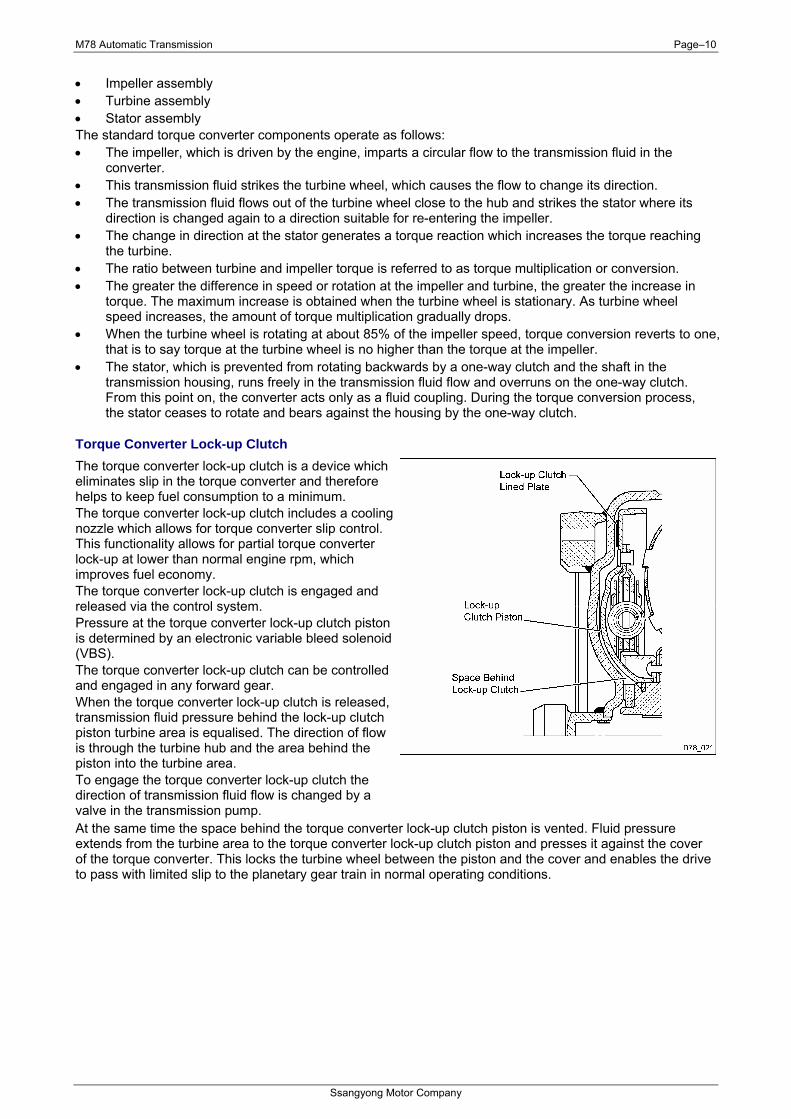
Double Planetary
The double planetary gear-set is splined to the output shaft. The double planetary gear-set consists of: • Two sun gears (forward and reverse) • Three short planetary gears meshing with sun gears • Three long planetary gears meshing with sun gears • One planetary gear carrier • One ring gear
M78 Automatic Transmission Page–9
Ssangyong Motor Company
Clutches and Brake Bands
Other shift elements in addition to the torque converter lock-up clutch are: • Three rotating multi-plate clutches C1, C2 & C3 • Two brake bands (front and rear) The multi-plate clutches are equalised in terms of dynamic pressure. Its piston is exposed to the transmission fluid flow on both sides in order to prevent pressure build up in the clutch as the speed ofrotation increases. This pressure equalisation is achieved by a piston dam. The advantages of this dynamic pressure equalisation are: • Reliable clutch engagement and release in all
speed ranges • Improved shift refinement
Torque Converter
The torque converter contains a single plate lock-up clutch. The lock-up clutch can be controlled and engaged in any forward gear. The clutch is applied by removing transmission fluid pressure from one side of the plate and applying pressure to the other. The torque converter transmits and multiplies torque. The torque converter is a three-element device consisting of:
M78 Automatic Transmission Page–10
Ssangyong Motor Company
• Impeller assembly • Turbine assembly • Stator assembly The standard torque converter components operate as follows: • The impeller, which is driven by the engine, imparts a circular flow to the transmission fluid in the
converter. • This transmission fluid strikes the turbine wheel, which causes the flow to change its direction. • The transmission fluid flows out of the turbine wheel close to the hub and strikes the stator where its
direction is changed again to a direction suitable for re-entering the impeller. • The change in direction at the stator generates a torque reaction which increases the torque reaching
the turbine. • The ratio between turbine and impeller torque is referred to as torque multiplication or conversion. • The greater the difference in speed or rotation at the impeller and turbine, the greater the increase in
torque. The maximum increase is obtained when the turbine wheel is stationary. As turbine wheel speed increases, the amount of torque multiplication gradually drops.
• When the turbine wheel is rotating at about 85% of the impeller speed, torque conversion reverts to one, that is to say torque at the turbine wheel is no higher than the torque at the impeller.
• The stator, which is prevented from rotating backwards by a one-way clutch and the shaft in the transmission housing, runs freely in the transmission fluid flow and overruns on the one-way clutch. From this point on, the converter acts only as a fluid coupling. During the torque conversion process, the stator ceases to rotate and bears against the housing by the one-way clutch.
Torque Converter Lock-up Clutch The torque converter lock-up clutch is a device which eliminates slip in the torque converter and therefore helps to keep fuel consumption to a minimum. The torque converter lock-up clutch includes a cooling nozzle which allows for torque converter slip control. This functionality allows for partial torque converter lock-up at lower than normal engine rpm, which improves fuel economy. The torque converter lock-up clutch is engaged and released via the control system. Pressure at the torque converter lock-up clutch piston is determined by an electronic variable bleed solenoid (VBS). The torque converter lock-up clutch can be controlled and engaged in any forward gear. When the torque converter lock-up clutch is released, transmission fluid pressure behind the lock-up clutch piston turbine area is equalised. The direction of flow is through the turbine hub and the area behind the piston into the turbine area. To engage the torque converter lock-up clutch the direction of transmission fluid flow is changed by a valve in the transmission pump. At the same time the space behind the torque converter lock-up clutch piston is vented. Fluid pressure extends from the turbine area to the torque converter lock-up clutch piston and presses it against the cover of the torque converter. This locks the turbine wheel between the piston and the cover and enables the drive to pass with limited slip to the planetary gear train in normal operating conditions.
M78 Automatic Transmission Page–11
Ssangyong Motor Company
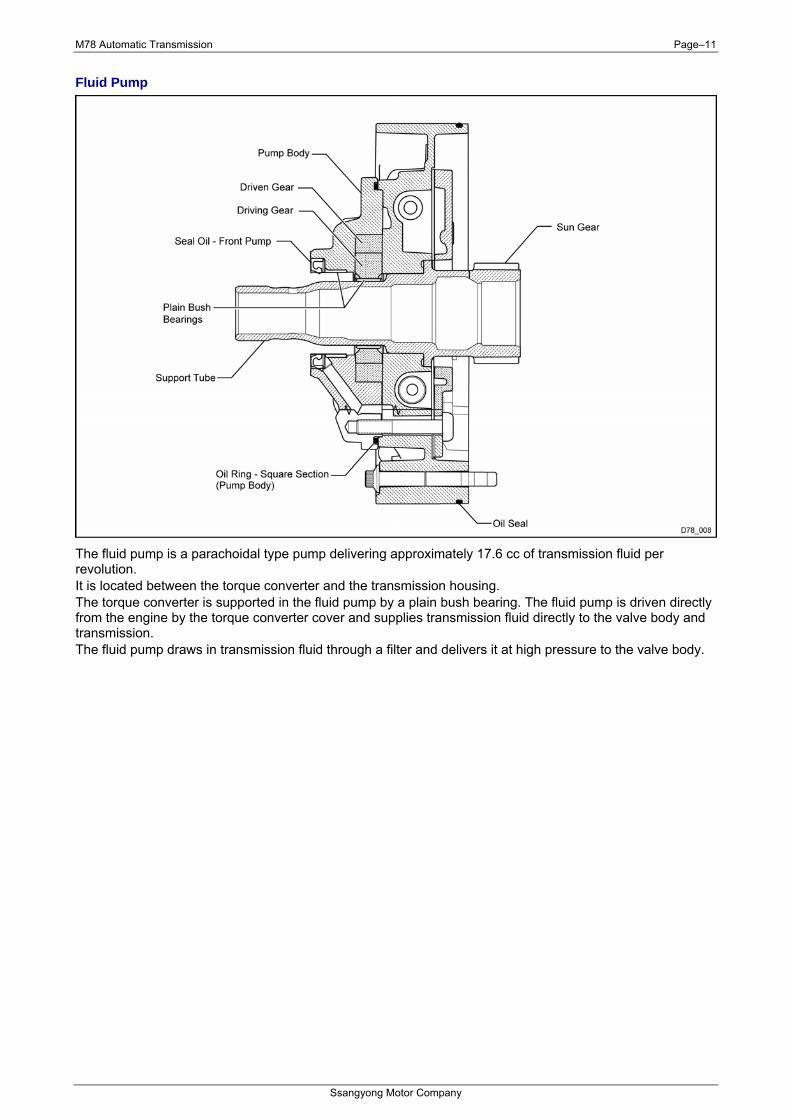
Fluid Pump
The fluid pump is a parachoidal type pump delivering approximately 17.6 cc of transmission fluid per revolution. It is located between the torque converter and the transmission housing. The torque converter is supported in the fluid pump by a plain bush bearing. The fluid pump is driven directly from the engine by the torque converter cover and supplies transmission fluid directly to the valve body and transmission. The fluid pump draws in transmission fluid through a filter and delivers it at high pressure to the valve body.
M78 Automatic Transmission Page–12
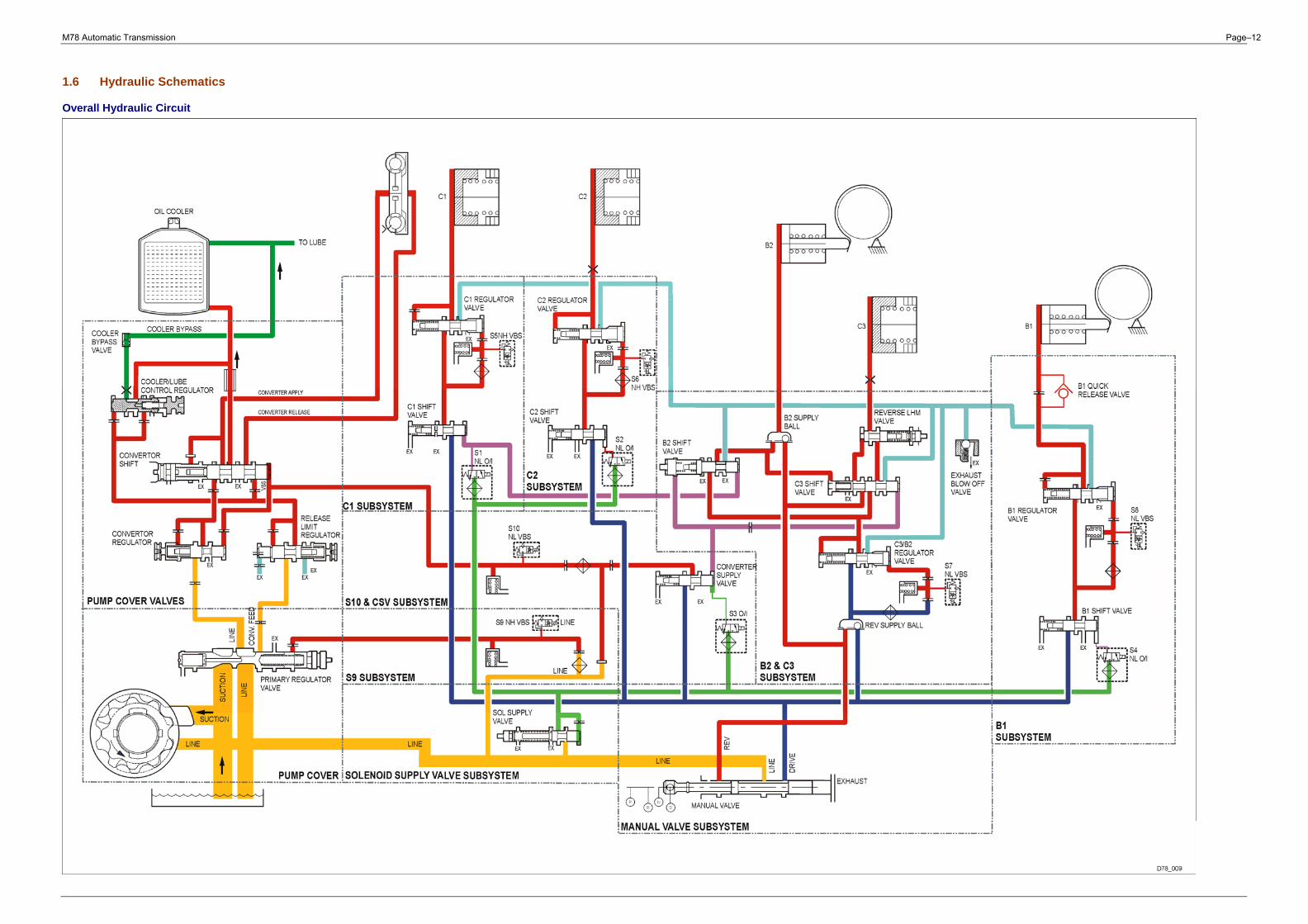
1.6 Hydraulic Schematics
Overall Hydraulic Circuit
M78 Automatic Transmission Page–13
Page intentionally left blank
M78 Automatic Transmission Page–14
Ssangyong Motor Company
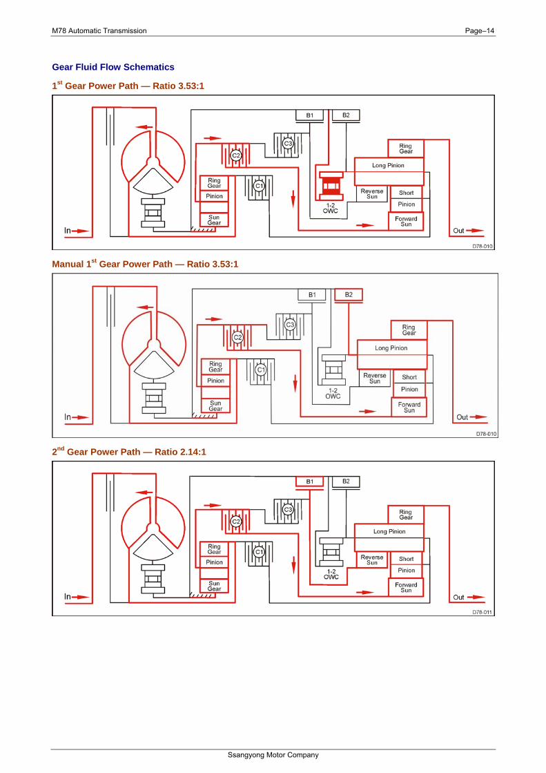
Gear Fluid Flow Schematics
1st Gear Power Path — Ratio 3.53:1
Manual 1st Gear Power Path — Ratio 3.53:1
2nd Gear Power Path — Ratio 2.14:1
M78 Automatic Transmission Page–15
Ssangyong Motor Company
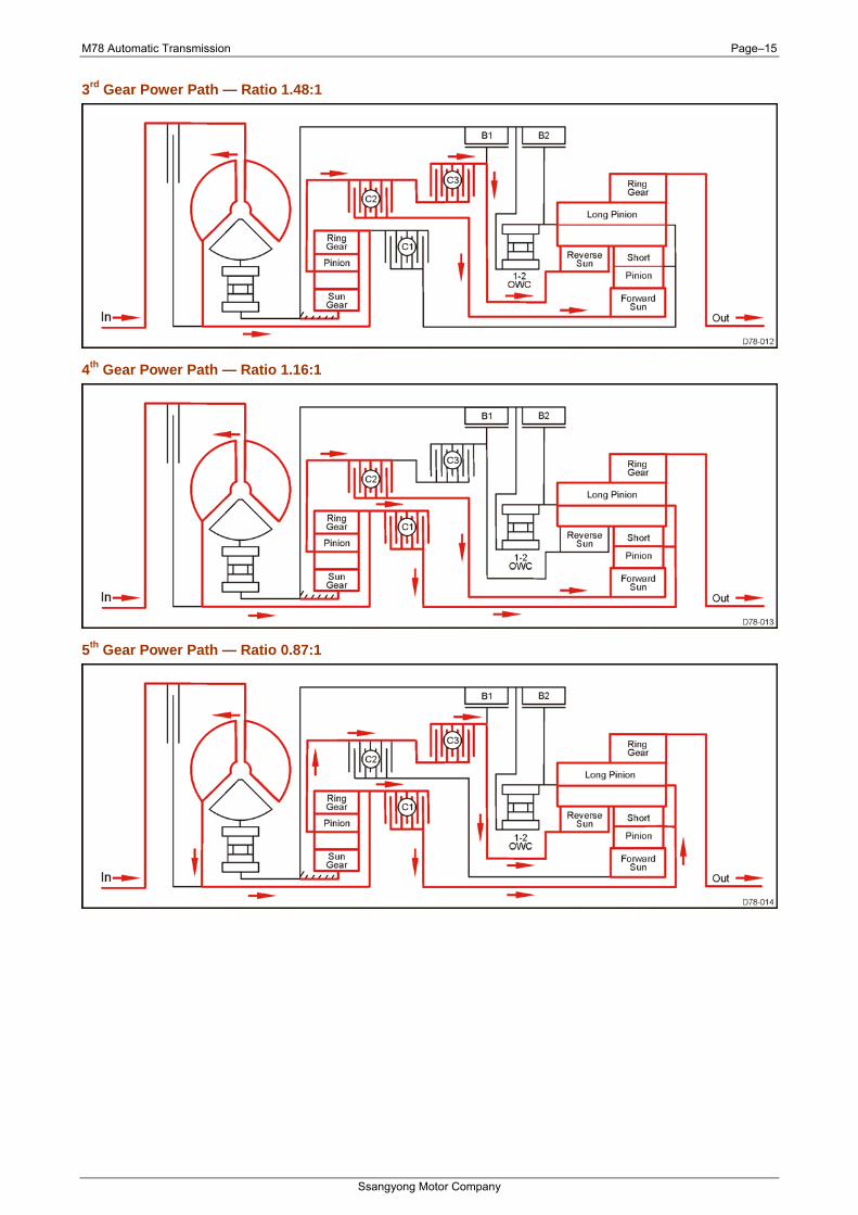
3rd Gear Power Path — Ratio 1.48:1
4th Gear Power Path — Ratio 1.16:1
5th Gear Power Path — Ratio 0.87:1
M78 Automatic Transmission Page–16
Ssangyong Motor Company
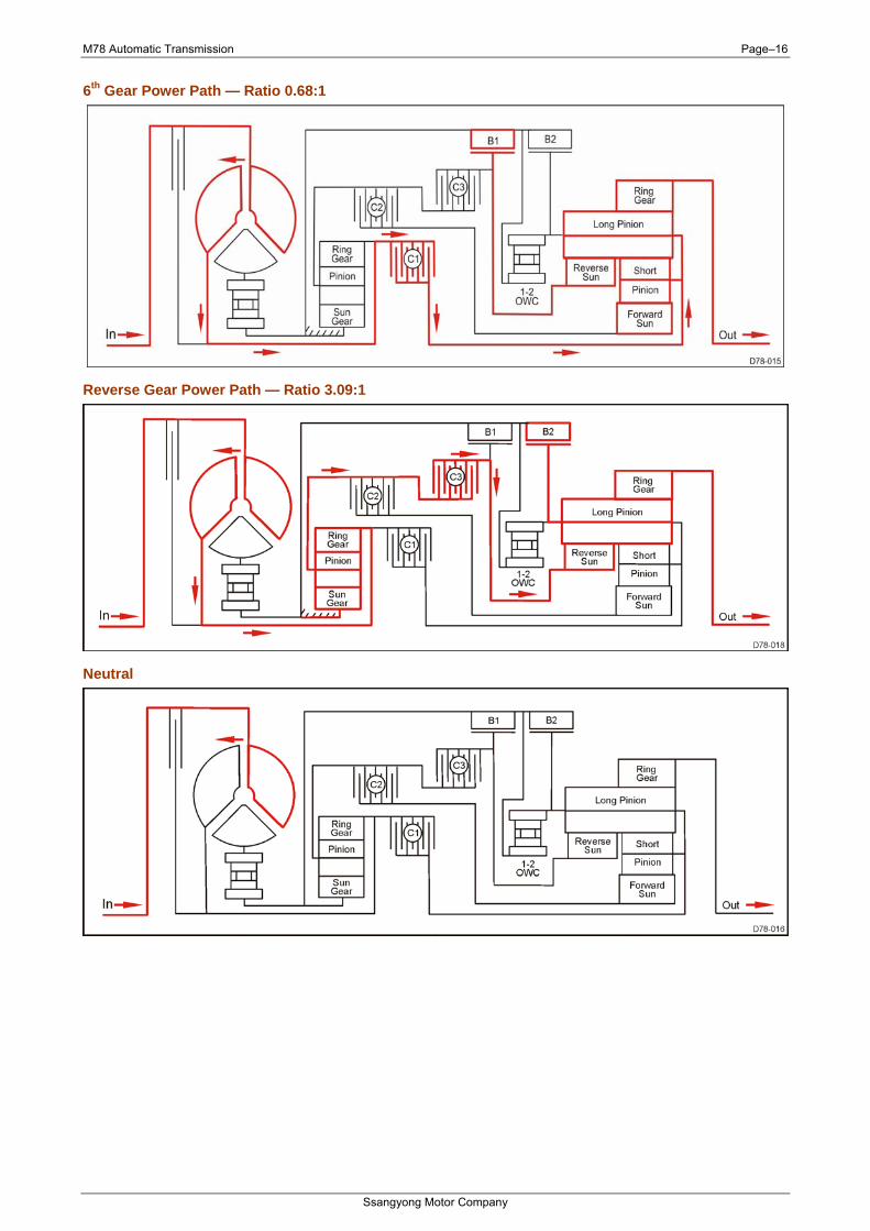
6th Gear Power Path — Ratio 0.68:1
Reverse Gear Power Path — Ratio 3.09:1
Neutral
M78 Automatic Transmission Page–17
Ssangyong Motor Company
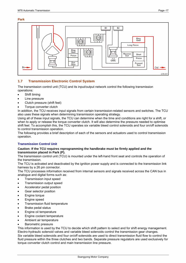
Park
1.7 Transmission Electronic Control System The transmission control unit (TCU) and its input/output network control the following transmission operations: • Shift timing • Line pressure • Clutch pressure (shift feel) • Torque converter clutch In addition, the TCU receives input signals from certain transmission-related sensors and switches. The TCU also uses these signals when determining transmission operating strategy. Using all of these input signals, the TCU can determine when the time and conditions are right for a shift, or when to apply or release the torque converter clutch. It will also determine the pressure needed to optimise shift feel. To accomplish this, the TCU operates six variable bleed control solenoids and four on/off solenoids to control transmission operation. The following provides a brief description of each of the sensors and actuators used to control transmission operation.
Transmission Control Unit Caution: If the TCU requires reprogramming the handbrake must be firmly applied and the transmission placed in Park (P). The transmission control unit (TCU) is mounted under the left-hand front seat and controls the operation of the transmission. The TCU is activated and deactivated by the ignition power supply and is connected to the transmission link harness by a 26 pin connector. The TCU processes information received from internal sensors and signals received across the CAN bus in analogue and digital forms such as: • Transmission input speed • Transmission output speed • Accelerator pedal position • Gear selector position • Engine torque • Engine speed • Transmission fluid temperature • Brake pedal status • Engine oil temperature • Engine coolant temperature • Ambient air temperature • Barometric pressure This information is used by the TCU to decide which shift pattern to select and for shift energy management. Electro-hydraulic solenoid valves and variable bleed solenoids control the transmission gear changes. Six variable bleed solenoids and four on/off solenoids are used to direct transmission fluid flow to control the fluid pressure within the three clutches and two bands. Separate pressure regulators are used exclusively for torque converter clutch control and main transmission line pressure.
M78 Automatic Transmission Page–18
Ssangyong Motor Company
The TCU monitors all TCU inputs and outputs to confirm correct system operation. If a fault occurs the TCU is able to perform default action and inform the driver of the problem through the instrument cluster warning lights. Detailed information is available via trouble codes which can be read with the service tool.
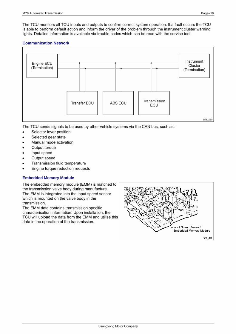
Communication Network
The TCU sends signals to be used by other vehicle systems via the CAN bus, such as: • Selector lever position • Selected gear state • Manual mode activation • Output torque • Input speed • Output speed • Transmission fluid temperature • Engine torque reduction requests
Embedded Memory Module The embedded memory module (EMM) is matched to the transmission valve body during manufacture. The EMM is integrated into the input speed sensor which is mounted on the valve body in the transmission. The EMM data contains transmission specific characterisation information. Upon installation, the TCU will upload the data from the EMM and utilise this data in the operation of the transmission.
M78 Automatic Transmission Page–19
Ssangyong Motor Company
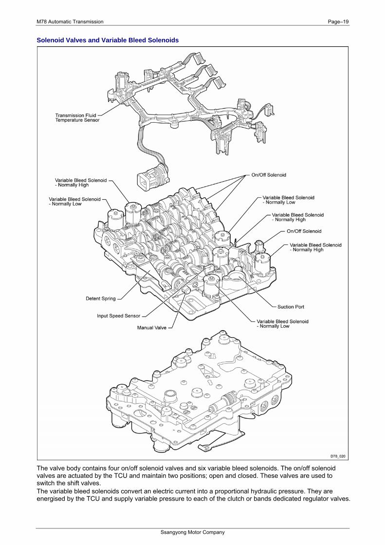
Solenoid Valves and Variable Bleed Solenoids
The valve body contains four on/off solenoid valves and six variable bleed solenoids. The on/off solenoid valves are actuated by the TCU and maintain two positions; open and closed. These valves are used to switch the shift valves. The variable bleed solenoids convert an electric current into a proportional hydraulic pressure. They are energised by the TCU and supply variable pressure to each of the clutch or bands dedicated regulator valves.
M78 Automatic Transmission Page–20
Ssangyong Motor Company
Sensor Inputs
Brake Pedal Position Switch The brake pedal position (BPP) switch tells the TCU when the brakes are applied. The BPP is also used to disengage the transmission gear selector (TGS) interlock when moving out of the Park position and as part of the shifting strategy.
Engine Intake Temperature Sensor The engine intake temperature (EIT) sensor detects intake air temperature and supplies the information to the TCU.
Barometric Pressure Sensor The barometric pressure (BARO) sensor detects the current air pressure and supplies the information to the TCU.
Accelerator Pedal Position Sensor The accelerator pedal position (APP) sensor is a potentiometer mounted on the accelerator pedal. The APP sensor detects the position of the accelerator pedal and sends this information to the TCU. The APP sensor signal is used for shift scheduling and TCC lock-up.
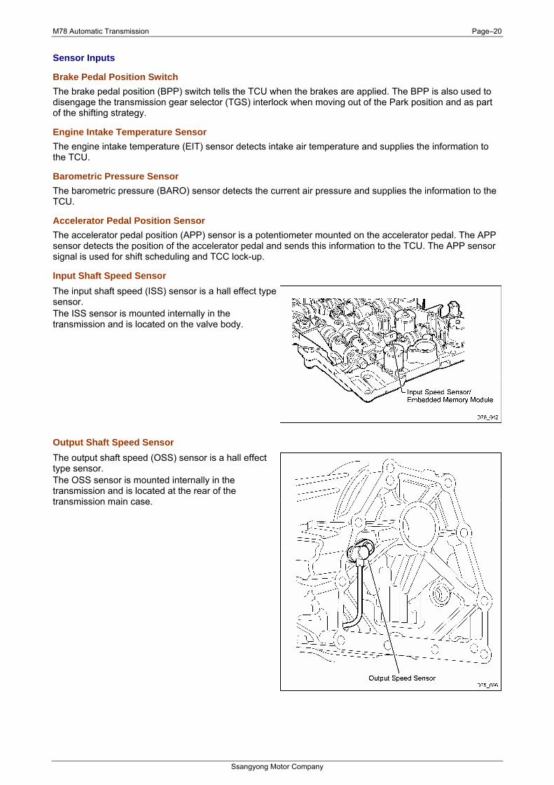
Input Shaft Speed Sensor The input shaft speed (ISS) sensor is a hall effect type sensor. The ISS sensor is mounted internally in the transmission and is located on the valve body.
Output Shaft Speed Sensor The output shaft speed (OSS) sensor is a hall effect type sensor. The OSS sensor is mounted internally in the transmission and is located at the rear of the transmission main case.
M78 Automatic Transmission Page–21
Ssangyong Motor Company
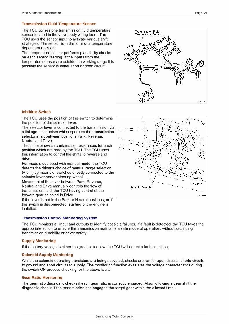
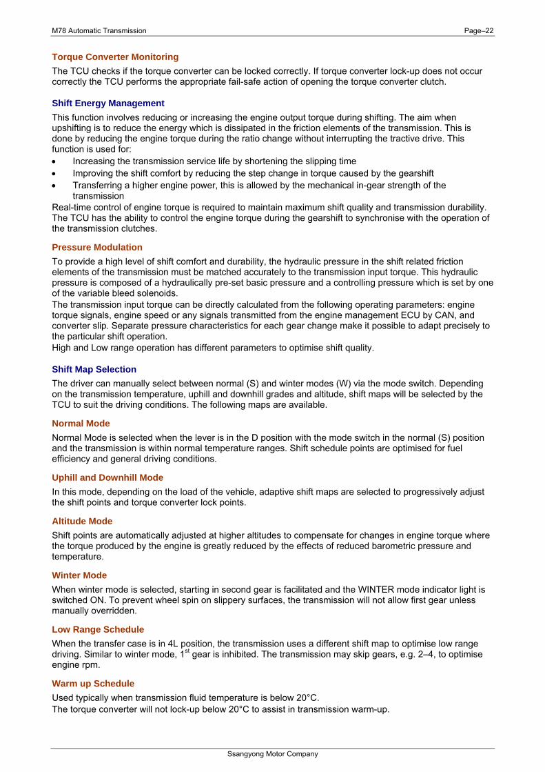
Transmission Fluid Temperature Sensor The TCU utilises one transmission fluid temperature sensor located in the valve body wiring loom. The TCU uses the sensor input to activate various shift strategies. The sensor is in the form of a temperature dependant resistor. The temperature sensor performs plausibility checks on each sensor reading. If the inputs from the temperature sensor are outside the working range it is possible the sensor is either short or open circuit.
Inhibitor Switch The TCU uses the position of this switch to determine the position of the selector lever. The selector lever is connected to the transmission via a linkage mechanism which operates the transmission selector shaft between positions Park, Reverse, Neutral and Drive. The inhibitor switch contains set resistances for each position which are read by the TCU. The TCU uses this information to control the shifts to reverse and drive. For models equipped with manual mode, the TCU detects the driver’s choice of manual range selection (+ or -) by means of switches directly connected to the selector lever and/or steering wheel. Movement of the lever between Park, Reverse, Neutral and Drive manually controls the flow of transmission fluid, the TCU having control of the forward gear selected in Drive. If the lever is not in the Park or Neutral positions, or if the switch is disconnected, starting of the engine is inhibited.
Transmission Control Monitoring System The TCU monitors all input and outputs to identify possible failures. If a fault is detected, the TCU takes the appropriate action to ensure the transmission maintains a safe mode of operation, without sacrificing transmission durability or driver safety.
Supply Monitoring If the battery voltage is either too great or too low, the TCU will detect a fault condition.
Solenoid Supply Monitoring While the solenoid operating transistors are being activated, checks are run for open circuits, shorts circuits to ground and short circuits to supply. The monitoring function evaluates the voltage characteristics during the switch ON process checking for the above faults.
Gear Ratio Monitoring The gear ratio diagnostic checks if each gear ratio is correctly engaged. Also, following a gear shift the diagnostic checks if the transmission has engaged the target gear within the allowed time.
M78 Automatic Transmission Page–22
Ssangyong Motor Company
Torque Converter Monitoring The TCU checks if the torque converter can be locked correctly. If torque converter lock-up does not occur correctly the TCU performs the appropriate fail-safe action of opening the torque converter clutch.
Shift Energy Management This function involves reducing or increasing the engine output torque during shifting. The aim when upshifting is to reduce the energy which is dissipated in the friction elements of the transmission. This is done by reducing the engine torque during the ratio change without interrupting the tractive drive. This function is used for: • Increasing the transmission service life by shortening the slipping time • Improving the shift comfort by reducing the step change in torque caused by the gearshift • Transferring a higher engine power, this is allowed by the mechanical in-gear strength of the
transmission Real-time control of engine torque is required to maintain maximum shift quality and transmission durability. The TCU has the ability to control the engine torque during the gearshift to synchronise with the operation of the transmission clutches.
Pressure Modulation To provide a high level of shift comfort and durability, the hydraulic pressure in the shift related friction elements of the transmission must be matched accurately to the transmission input torque. This hydraulic pressure is composed of a hydraulically pre-set basic pressure and a controlling pressure which is set by one of the variable bleed solenoids. The transmission input torque can be directly calculated from the following operating parameters: engine torque signals, engine speed or any signals transmitted from the engine management ECU by CAN, and converter slip. Separate pressure characteristics for each gear change make it possible to adapt precisely to the particular shift operation. High and Low range operation has different parameters to optimise shift quality.
Shift Map Selection The driver can manually select between normal (S) and winter modes (W) via the mode switch. Depending on the transmission temperature, uphill and downhill grades and altitude, shift maps will be selected by the TCU to suit the driving conditions. The following maps are available.
Normal Mode Normal Mode is selected when the lever is in the D position with the mode switch in the normal (S) position and the transmission is within normal temperature ranges. Shift schedule points are optimised for fuel efficiency and general driving conditions.
Uphill and Downhill Mode In this mode, depending on the load of the vehicle, adaptive shift maps are selected to progressively adjust the shift points and torque converter lock points.
Altitude Mode Shift points are automatically adjusted at higher altitudes to compensate for changes in engine torque where the torque produced by the engine is greatly reduced by the effects of reduced barometric pressure and temperature.
Winter Mode When winter mode is selected, starting in second gear is facilitated and the WINTER mode indicator light is switched ON. To prevent wheel spin on slippery surfaces, the transmission will not allow first gear unless manually overridden.
Low Range Schedule When the transfer case is in 4L position, the transmission uses a different shift map to optimise low range driving. Similar to winter mode, 1st gear is inhibited. The transmission may skip gears, e.g. 2–4, to optimise engine rpm.
Warm up Schedule Used typically when transmission fluid temperature is below 20°C. The torque converter will not lock-up below 20°C to assist in transmission warm-up.
M78 Automatic Transmission Page–23
Ssangyong Motor Company
Hot Mode The hot mode is progressively applied between temperatures of 110° – 145°C. The torque converter lock-up is increased to prevent heat generation by the torque converter. As additional assistance to the hot mode, the following are activated: • Above 110°C – the electrical radiator fans are switch ON • Above 130°C – the engine torque will be reduced and the WINTER light on the instrument cluster will
flash • Above 145°C – the transmission will neutralise until the fluid temperature falls below 120°C as a final
protection. Activation of the hot mode inhibits other transmission performance features including uphill and downhill compensation and altitude compensation. Some degradation in shift feel may be experienced as the torque converter is not unlocked during shifting. The fluid temperature must be below 105°C to exit all hot modes.
Cruise When cruise control is activated the engine ECU may request the transmission to downshift under trailing throttle conditions to increase engine braking.

M78 Automatic Transmission Page–24
Ssangyong Motor Company
2 Diagnosis and Testing
2.1 Wiring Diagram
M78 Automatic Transmission Page–25
Ssangyong Motor Company
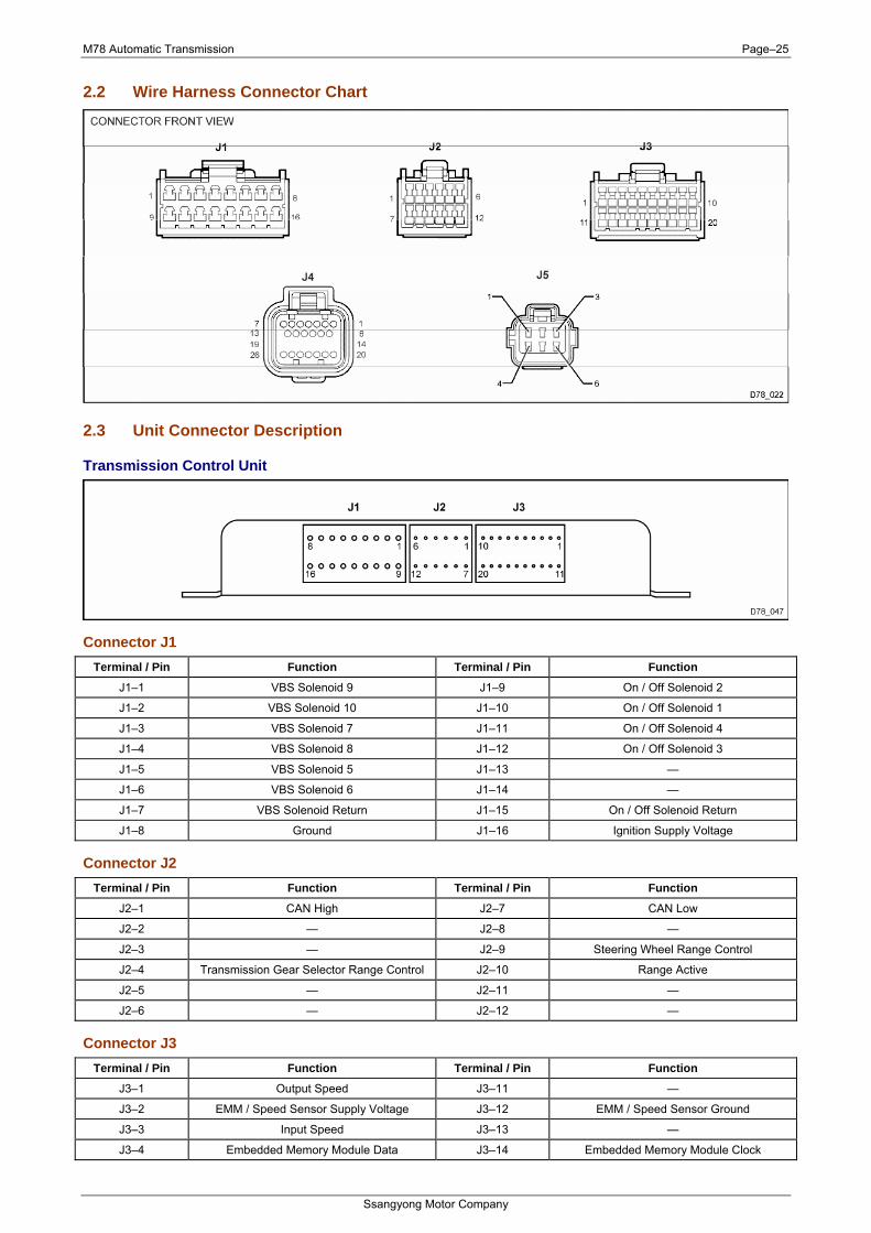
2.2 Wire Harness Connector Chart
2.3 Unit Connector Description
Transmission Control Unit
Connector J1 Terminal / Pin Function Terminal / Pin Function
J1–1 VBS Solenoid 9 J1–9 On / Off Solenoid 2
J1–2 VBS Solenoid 10 J1–10 On / Off Solenoid 1
J1–3 VBS Solenoid 7 J1–11 On / Off Solenoid 4
J1–4 VBS Solenoid 8 J1–12 On / Off Solenoid 3
J1–5 VBS Solenoid 5 J1–13 —
J1–6 VBS Solenoid 6 J1–14 —
J1–7 VBS Solenoid Return J1–15 On / Off Solenoid Return
J1–8 Ground J1–16 Ignition Supply Voltage
Connector J2 Terminal / Pin Function Terminal / Pin Function
J2–1 CAN High J2–7 CAN Low
J2–2 — J2–8 —
J2–3 — J2–9 Steering Wheel Range Control
J2–4 Transmission Gear Selector Range Control J2–10 Range Active
J2–5 — J2–11 —
J2–6 — J2–12 —
Connector J3 Terminal / Pin Function Terminal / Pin Function
J3–1 Output Speed J3–11 —
J3–2 EMM / Speed Sensor Supply Voltage J3–12 EMM / Speed Sensor Ground
J3–3 Input Speed J3–13 —
J3–4 Embedded Memory Module Data J3–14 Embedded Memory Module Clock

M78 Automatic Transmission Page–26
Ssangyong Motor Company
J3–5 — J3–15 Switch Ground
J3–6 Mode J3–16 —
J3–7 Gear Lever J3–17 Gear Lever Ground
J3–8 Transmission Fluid Temperature J3–18 Transmission Fluid Temperature Return
J3–9 — J3–19 —
J3–10 — J3–20 —
Transmission
Connector J4 Terminal / Pin Function Terminal / Pin Function
J4–1 VBS Solenoid Return J4–14 —
J4–2 VBS Solenoid 5 J4–15 —
J4–3 VBS Solenoid 6 J4–16 —
J4–4 VBS Solenoid 7 J4–17 —
J4–5 VBS Solenoid 8 J4–18 —
J4–6 VBS Solenoid 9 J4–19 —
J4–7 VBS Solenoid 10 J4–20 On/Off Solenoid Return
J4–8 EMM Data / Speed Sensor Ground J4–21 On/Off Solenoid
J4–9 EMM / Speed Sensor Supply Voltage J4–22 On/Off Solenoid
J4–10 Output Speed J4–23 On/Off Solenoid
J4–11 Input Speed J4–24 On/Off Solenoid
J4–12 Embedded Memory Module Data J4–25 Transmission Fluid Temperature Return
J4–13 Embedded Memory Module Clock J4–26 Transmission Fluid Temperature Input
Inhibitor Switch
Connector J5 Terminal / Pin Function Terminal / Pin Function
J5–1 Reverse Circuit J5–4 Gear Lever Ground
J5–2 Starter Circuit J5–5 Gear Lever
J5–3 Starter Circuit J5–6 Reverse Circuit
M78 Automatic Transmission Page–27
Ssangyong Motor Company
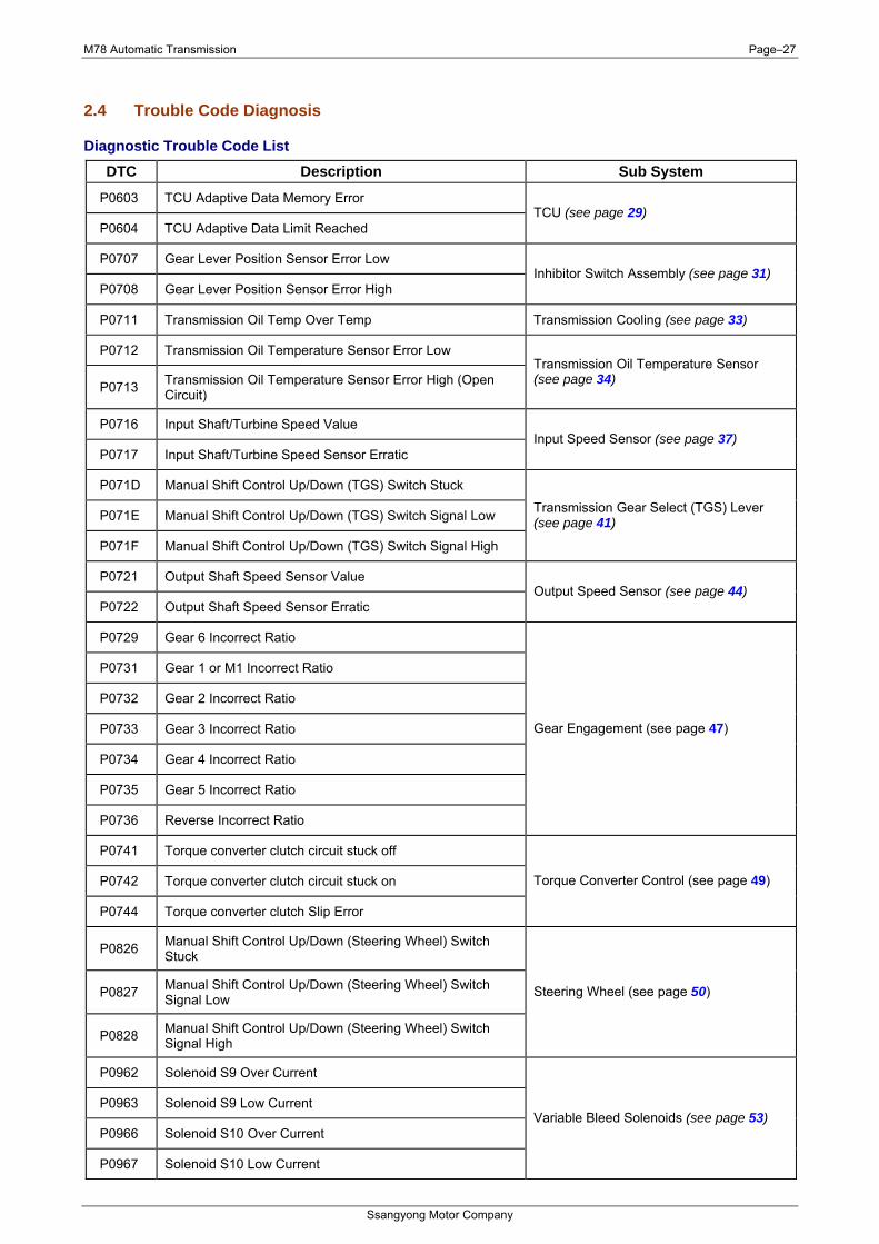
2.4 Trouble Code Diagnosis
Diagnostic Trouble Code List DTC Description Sub System
P0603 TCU Adaptive Data Memory Error
P0604 TCU Adaptive Data Limit Reached TCU (see page 29)
P0707 Gear Lever Position Sensor Error Low
P0708 Gear Lever Position Sensor Error High Inhibitor Switch Assembly (see page 31)
P0711 Transmission Oil Temp Over Temp Transmission Cooling (see page 33)
P0712 Transmission Oil Temperature Sensor Error Low
P0713 Transmission Oil Temperature Sensor Error High (Open Circuit)
Transmission Oil Temperature Sensor (see page 34)
P0716 Input Shaft/Turbine Speed Value
P0717 Input Shaft/Turbine Speed Sensor Erratic Input Speed Sensor (see page 37)
P071D Manual Shift Control Up/Down (TGS) Switch Stuck
P071E Manual Shift Control Up/Down (TGS) Switch Signal Low
P071F Manual Shift Control Up/Down (TGS) Switch Signal High
Transmission Gear Select (TGS) Lever (see page 41)
P0721 Output Shaft Speed Sensor Value
P0722 Output Shaft Speed Sensor Erratic Output Speed Sensor (see page 44)
P0729 Gear 6 Incorrect Ratio
P0731 Gear 1 or M1 Incorrect Ratio
P0732 Gear 2 Incorrect Ratio
P0733 Gear 3 Incorrect Ratio
P0734 Gear 4 Incorrect Ratio
P0735 Gear 5 Incorrect Ratio
P0736 Reverse Incorrect Ratio
Gear Engagement (see page 47)
P0741 Torque converter clutch circuit stuck off
P0742 Torque converter clutch circuit stuck on
P0744 Torque converter clutch Slip Error
Torque Converter Control (see page 49)
P0826 Manual Shift Control Up/Down (Steering Wheel) Switch Stuck
P0827 Manual Shift Control Up/Down (Steering Wheel) Switch Signal Low
P0828 Manual Shift Control Up/Down (Steering Wheel) Switch Signal High
Steering Wheel (see page 50)
P0962 Solenoid S9 Over Current
P0963 Solenoid S9 Low Current
P0966 Solenoid S10 Over Current
P0967 Solenoid S10 Low Current
Variable Bleed Solenoids (see page 53)
M78 Automatic Transmission Page–28
Ssangyong Motor Company
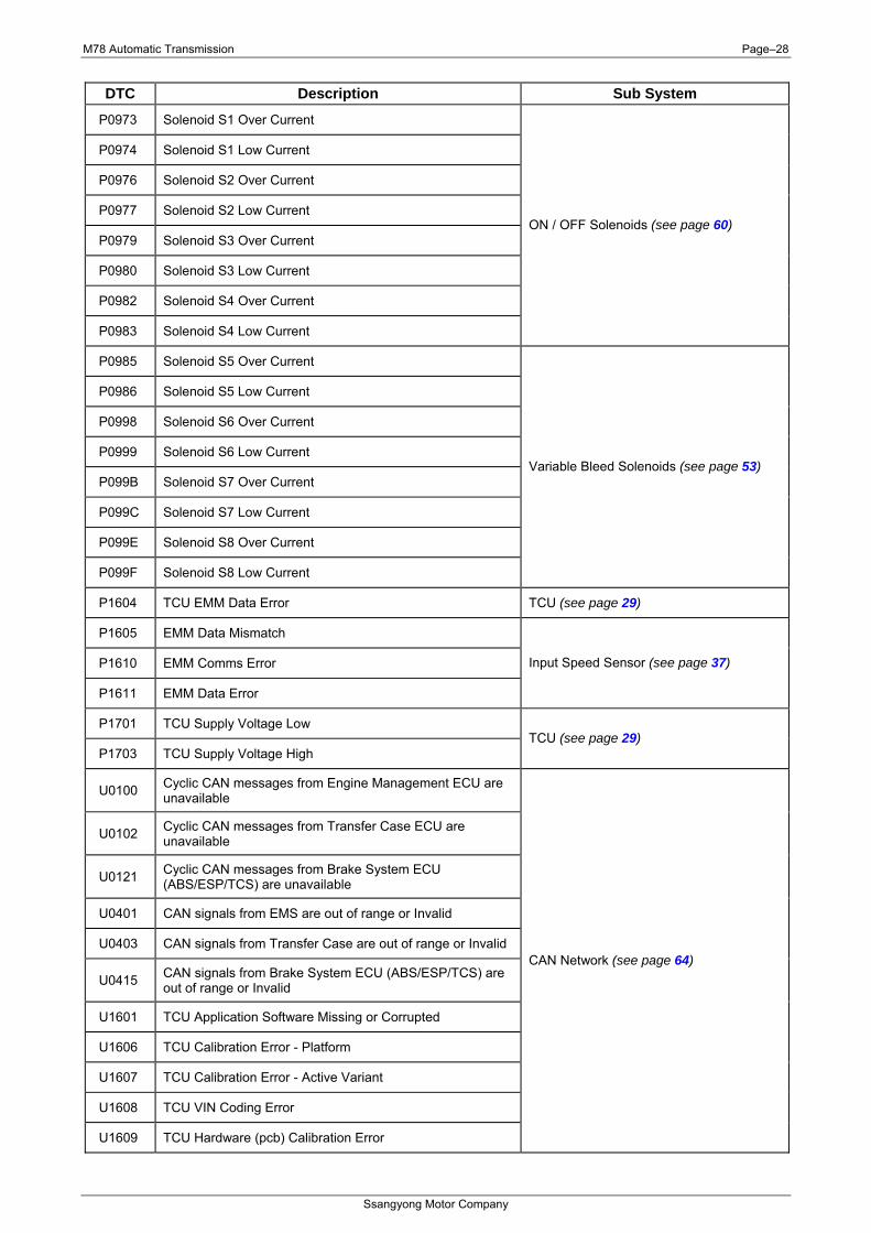
DTC Description Sub System
P0973 Solenoid S1 Over Current
P0974 Solenoid S1 Low Current
P0976 Solenoid S2 Over Current
P0977 Solenoid S2 Low Current
P0979 Solenoid S3 Over Current
P0980 Solenoid S3 Low Current
P0982 Solenoid S4 Over Current
P0983 Solenoid S4 Low Current
ON / OFF Solenoids (see page 60)
P0985 Solenoid S5 Over Current
P0986 Solenoid S5 Low Current
P0998 Solenoid S6 Over Current
P0999 Solenoid S6 Low Current
P099B Solenoid S7 Over Current
P099C Solenoid S7 Low Current
P099E Solenoid S8 Over Current
P099F Solenoid S8 Low Current
Variable Bleed Solenoids (see page 53)
P1604 TCU EMM Data Error TCU (see page 29)
P1605 EMM Data Mismatch
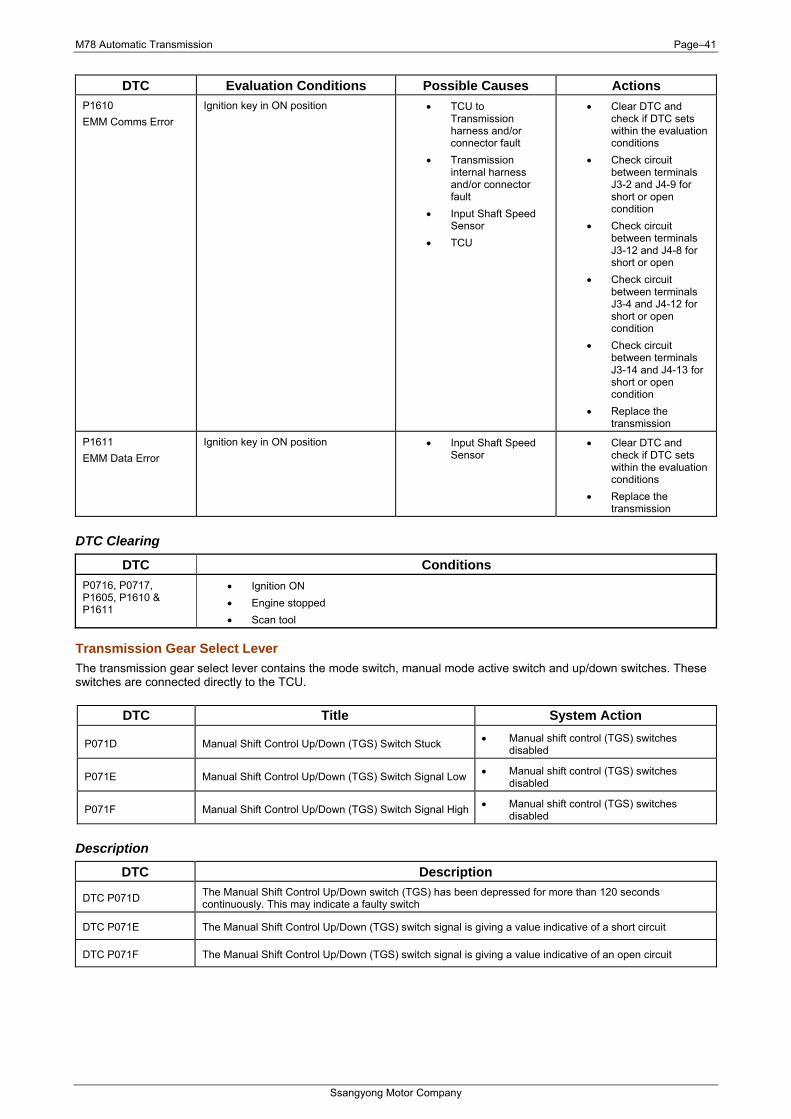
P1610 EMM Comms Error
P1611 EMM Data Error
Input Speed Sensor (see page 37)
P1701 TCU Supply Voltage Low
P1703 TCU Supply Voltage High TCU (see page 29)
U0100 Cyclic CAN messages from Engine Management ECU are unavailable
U0102 Cyclic CAN messages from Transfer Case ECU are unavailable
U0121 Cyclic CAN messages from Brake System ECU (ABS/ESP/TCS) are unavailable
U0401 CAN signals from EMS are out of range or Invalid
U0403 CAN signals from Transfer Case are out of range or Invalid
U0415 CAN signals from Brake System ECU (ABS/ESP/TCS) are out of range or Invalid
U1601 TCU Application Software Missing or Corrupted
U1606 TCU Calibration Error - Platform
U1607 TCU Calibration Error - Active Variant
U1608 TCU VIN Coding Error
U1609 TCU Hardware (pcb) Calibration Error
CAN Network (see page 64)
M78 Automatic Transmission Page–29
Ssangyong Motor Company
Sub-System
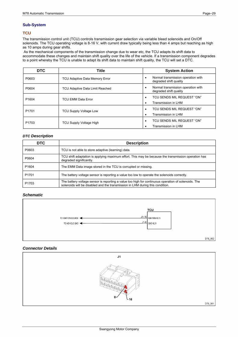
TCU The transmission control unit (TCU) controls transmission gear selection via variable bleed solenoids and On/Off solenoids. The TCU operating voltage is 8-16 V, with current draw typically being less than 4 amps but reaching as high as 10 amps during gear shifts. As the mechanical components of the transmission change due to wear etc, the TCU adapts its shift data to accommodate these changes and maintain shift quality over the life of the vehicle. If a transmission component degrades to a point whereby the TCU is unable to adapt its shift data to maintain shift quality, the TCU will set a DTC.
DTC Title System Action
P0603 TCU Adaptive Data Memory Error • Normal transmission operation with degraded shift quality
P0604 TCU Adaptive Data Limit Reached • Normal transmission operation with degraded shift quality
P1604 TCU EMM Data Error • TCU SENDS MIL REQUEST “ON”
• Transmission in LHM
P1701 TCU Supply Voltage Low • TCU SENDS MIL REQUEST “ON”
• Transmission in LHM
P1703 TCU Supply Voltage High • TCU SENDS MIL REQUEST “ON”
• Transmission in LHM
DTC Description
DTC Description P0603 TCU is not able to store adaptive (learning) data.
P0604 TCU shift adaptation is applying maximum effort. This may be because the transmission operation has degraded significantly.
P1604 The EMM Data image stored in the TCU is corrupted or missing.
P1701 The battery voltage sensor is reporting a value too low to operate the solenoids correctly.
P1703 The battery voltage sensor is reporting a value too high for continuous operation of solenoids. The solenoids will be disabled and the transmission in LHM during this condition.
Schematic
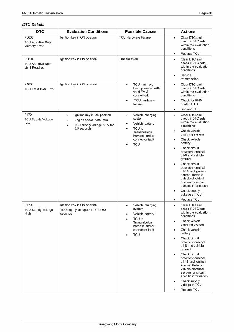
Connector Details
M78 Automatic Transmission Page–30
Ssangyong Motor Company
DTC Details
DTC Evaluation Conditions Possible Causes Actions P0603 TCU Adaptive Data Memory Error
Ignition key in ON position TCU Hardware Failure • Clear DTC and check if DTC sets within the evaluation conditions
• Replace TCU
P0604 TCU Adaptive Data Limit Reached
Ignition key in ON position Transmission • Clear DTC and check if DTC sets within the evaluation conditions
• Service transmission
P1604 TCU EMM Data Error
Ignition key in ON position • TCU has never been powered with valid EMM connected.
• TCU hardware failure.
• Clear DTC and check if DTC sets within the evaluation conditions
• Check for EMM related DTC.
• Replace TCU
P1701 TCU Supply Voltage Low
• Ignition key in ON position • Engine speed >300 rpm • TCU supply voltage <8 V for
0.5 seconds
• Vehicle charging system
• Vehicle battery • TCU to
Transmission harness and/or connector fault
• TCU
• Clear DTC and check if DTC sets within the evaluation conditions
• Check vehicle charging system
• Check vehicle battery
• Check circuit between terminal J1-8 and vehicle ground
• Check circuit between terminal J1-16 and ignition source. Refer to vehicle electrical section for circuit specific information
• Check supply voltage at TCU
• Replace TCU
P1703 TCU Supply Voltage High
Ignition key in ON position TCU supply voltage >17 V for 60 seconds
• Vehicle charging system
• Vehicle battery • TCU to
Transmission harness and/or connector fault
• TCU
• Clear DTC and check if DTC sets within the evaluation conditions
• Check vehicle charging system
• Check vehicle battery
• Check circuit between terminal J1-8 and vehicle ground
• Check circuit between terminal J1-16 and ignition source. Refer to vehicle electrical section for circuit specific information
• Check supply voltage at TCU
• Replace TCU
M78 Automatic Transmission Page–31
Ssangyong Motor Company
DTC Clearing
DTC Conditions P0603, P0604, P1604, P1701 & P1703
• Ignition ON • Engine stopped • Scan tool
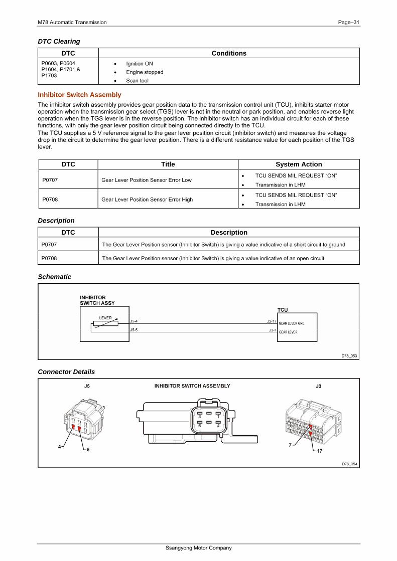
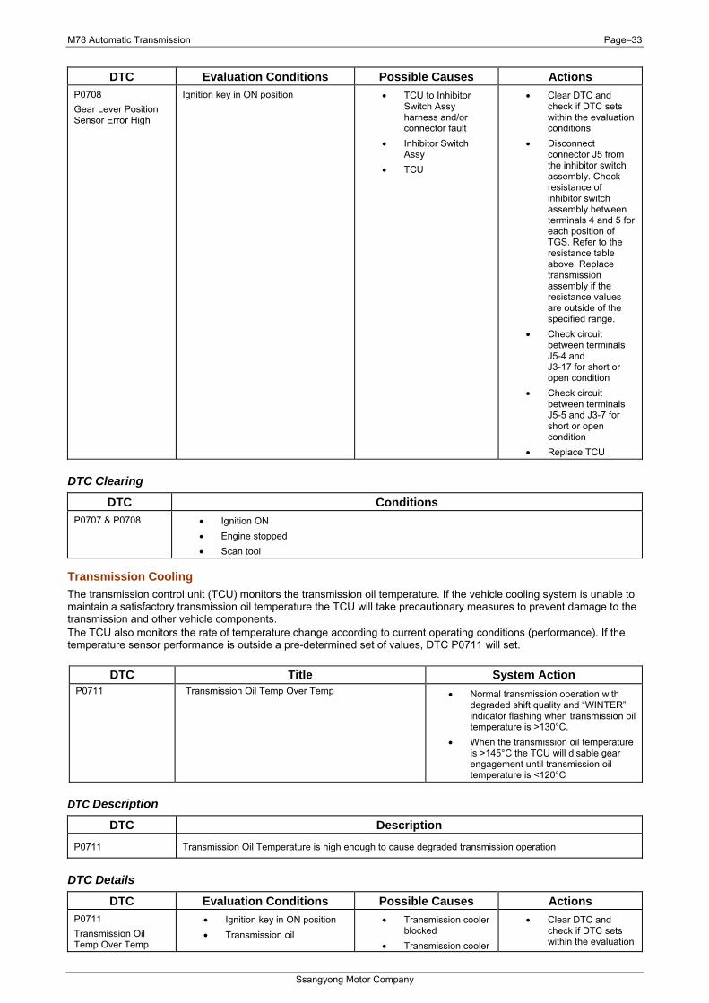
Inhibitor Switch Assembly The inhibitor switch assembly provides gear position data to the transmission control unit (TCU), inhibits starter motor operation when the transmission gear select (TGS) lever is not in the neutral or park position, and enables reverse light operation when the TGS lever is in the reverse position. The inhibitor switch has an individual circuit for each of these functions, with only the gear lever position circuit being connected directly to the TCU. The TCU supplies a 5 V reference signal to the gear lever position circuit (inhibitor switch) and measures the voltage drop in the circuit to determine the gear lever position. There is a different resistance value for each position of the TGS lever.
DTC Title System Action
P0707 Gear Lever Position Sensor Error Low • TCU SENDS MIL REQUEST “ON”
• Transmission in LHM
P0708 Gear Lever Position Sensor Error High • TCU SENDS MIL REQUEST “ON”
• Transmission in LHM
Description
DTC Description
P0707 The Gear Lever Position sensor (Inhibitor Switch) is giving a value indicative of a short circuit to ground
P0708 The Gear Lever Position sensor (Inhibitor Switch) is giving a value indicative of an open circuit
Schematic
Connector Details
M78 Automatic Transmission Page–32
Ssangyong Motor Company
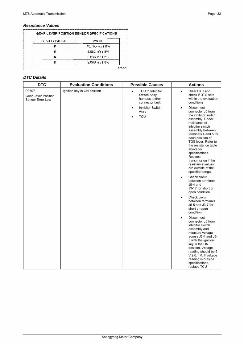
Resistance Values
DTC Details
DTC Evaluation Conditions Possible Causes Actions P0707 Gear Lever Position Sensor Error Low
Ignition key in ON position • TCU to Inhibitor Switch Assy harness and/or connector fault
• Inhibitor Switch Assy
• TCU
• Clear DTC and check if DTC sets within the evaluation conditions
• Disconnect connector J5 from the inhibitor switch assembly. Check resistance of inhibitor switch assembly between terminals 4 and 5 for each position of TGS lever. Refer to the resistance table above for specifications. Replace transmission if the resistance values are outside of the specified range.
• Check circuit between terminals J5-4 and J3-17 for short or open condition
• Check circuit between terminals J5-5 and J3-7 for short or open condition
• Disconnect connector J5 from inhibitor switch assembly and measure voltage across J5-4 and J5-5 with the ignition key in the ON position. Voltage reading should be 5 V ± 0.1 V. If voltage reading is outside specifications, replace TCU
M78 Automatic Transmission Page–33
Ssangyong Motor Company
DTC Evaluation Conditions Possible Causes Actions P0708 Gear Lever Position Sensor Error High
Ignition key in ON position • TCU to Inhibitor Switch Assy harness and/or connector fault
• Inhibitor Switch Assy
• TCU
• Clear DTC and check if DTC sets within the evaluation conditions
• Disconnect connector J5 from the inhibitor switch assembly. Check resistance of inhibitor switch assembly between terminals 4 and 5 for each position of TGS. Refer to the resistance table above. Replace transmission assembly if the resistance values are outside of the specified range.
• Check circuit between terminals J5-4 and J3-17 for short or open condition
• Check circuit between terminals J5-5 and J3-7 for short or open condition
• Replace TCU
DTC Clearing
DTC Conditions P0707 & P0708 • Ignition ON
• Engine stopped • Scan tool
Transmission Cooling The transmission control unit (TCU) monitors the transmission oil temperature. If the vehicle cooling system is unable to maintain a satisfactory transmission oil temperature the TCU will take precautionary measures to prevent damage to the transmission and other vehicle components. The TCU also monitors the rate of temperature change according to current operating conditions (performance). If the temperature sensor performance is outside a pre-determined set of values, DTC P0711 will set.
DTC Title System Action P0711 Transmission Oil Temp Over Temp • Normal transmission operation with
degraded shift quality and “WINTER” indicator flashing when transmission oil temperature is >130°C.
• When the transmission oil temperature is >145°C the TCU will disable gear engagement until transmission oil temperature is <120°C
DTC Description
DTC Description
P0711 Transmission Oil Temperature is high enough to cause degraded transmission operation
DTC Details
DTC Evaluation Conditions Possible Causes Actions P0711 Transmission Oil Temp Over Temp
• Ignition key in ON position • Transmission oil
• Transmission cooler blocked
• Transmission cooler
• Clear DTC and check if DTC sets within the evaluation
M78 Automatic Transmission Page–34
Ssangyong Motor Company
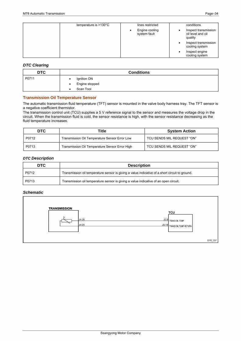
temperature is >130°C lines restricted • Engine cooling
system fault
conditions • Inspect transmission
oil level and oil quality
• Inspect transmission cooling system
• Inspect engine cooling system
DTC Clearing
DTC Conditions P0711 • Ignition ON
• Engine stopped • Scan Tool
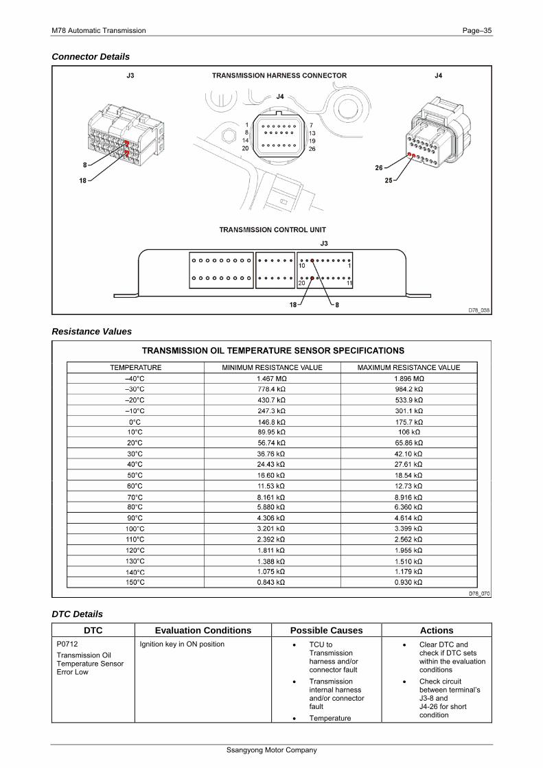
Transmission Oil Temperature Sensor The automatic transmission fluid temperature (TFT) sensor is mounted in the valve body harness tray. The TFT sensor is a negative coefficient thermistor. The transmission control unit (TCU) supplies a 5 V reference signal to the sensor and measures the voltage drop in the circuit. When the transmission fluid is cold, the sensor resistance is high, with the sensor resistance decreasing as the fluid temperature increases.
DTC Title System Action P0712 Transmission Oil Temperature Sensor Error Low TCU SENDS MIL REQUEST “ON”
P0713 Transmission Oil Temperature Sensor Error High TCU SENDS MIL REQUEST “ON”
DTC Description
DTC Description
P0712 Transmission oil temperature sensor is giving a value indicative of a short circuit to ground.
P0713 Transmission oil temperature sensor is giving a value indicative of an open circuit.
Schematic
M78 Automatic Transmission Page–35
Ssangyong Motor Company
Connector Details
Resistance Values
DTC Details
DTC Evaluation Conditions Possible Causes Actions P0712 Transmission Oil Temperature Sensor Error Low
Ignition key in ON position • TCU to Transmission harness and/or connector fault
• Transmission internal harness and/or connector fault
• Temperature
• Clear DTC and check if DTC sets within the evaluation conditions
• Check circuit between terminal’s J3-8 and J4-26 for short condition
M78 Automatic Transmission Page–36
Ssangyong Motor Company
DTC Evaluation Conditions Possible Causes Actions sensor.
• TCU • Check circuit
between terminal’s J3-18 and J4-25 for short condition
• Disconnect transmission connector J4. Check resistance of transmission oil temp. sensor between terminals J4-25 and J4-26. Refer to the resistance table above for specifications. Replace transmission assembly if the resistance values are outside of the specified range
• Disconnect connector J3 from the TCU and measure voltage across TCU terminals (TCU side) J3-8 and J3-18 with the ignition key in the ON position. Voltage reading should be 5 V ± 0.1 V. If voltage reading is outside specifications, replace TCU
P0713 Transmission Oil Temperature Sensor Error High
Ignition key in ON position • TCU to Transmission harness and/or connector fault
• Transmission internal harness and/or connector fault
• Temperature sensor• TCU
• Clear DTC and check if DTC sets within the evaluation conditions
• Check circuit between terminal’s J3-8 and J4-26 for open condition
• Check circuit between terminal’s J3-18 and J4-25 for open condition
• Disconnect transmission connector J4. Check resistance of transmission oil temp. sensor between terminals J4-25 and J4-26. Refer to the resistance table above for specifications. Replace transmission assembly if the resistance values are outside of the specified range
• Disconnect connector J3 from the TCU and measure voltage across TCU terminals (TCU side) J3-8 and J3-18 with
M78 Automatic Transmission Page–37
Ssangyong Motor Company
DTC Evaluation Conditions Possible Causes Actions the ignition key in the ON position. Voltage reading should be 5 V ± 0.1 V. If voltage reading is outside specifications, replace TCU
DTC Clearing
DTC Conditions P0712 & P0713 • Ignition ON
• Engine stopped • Scan tool
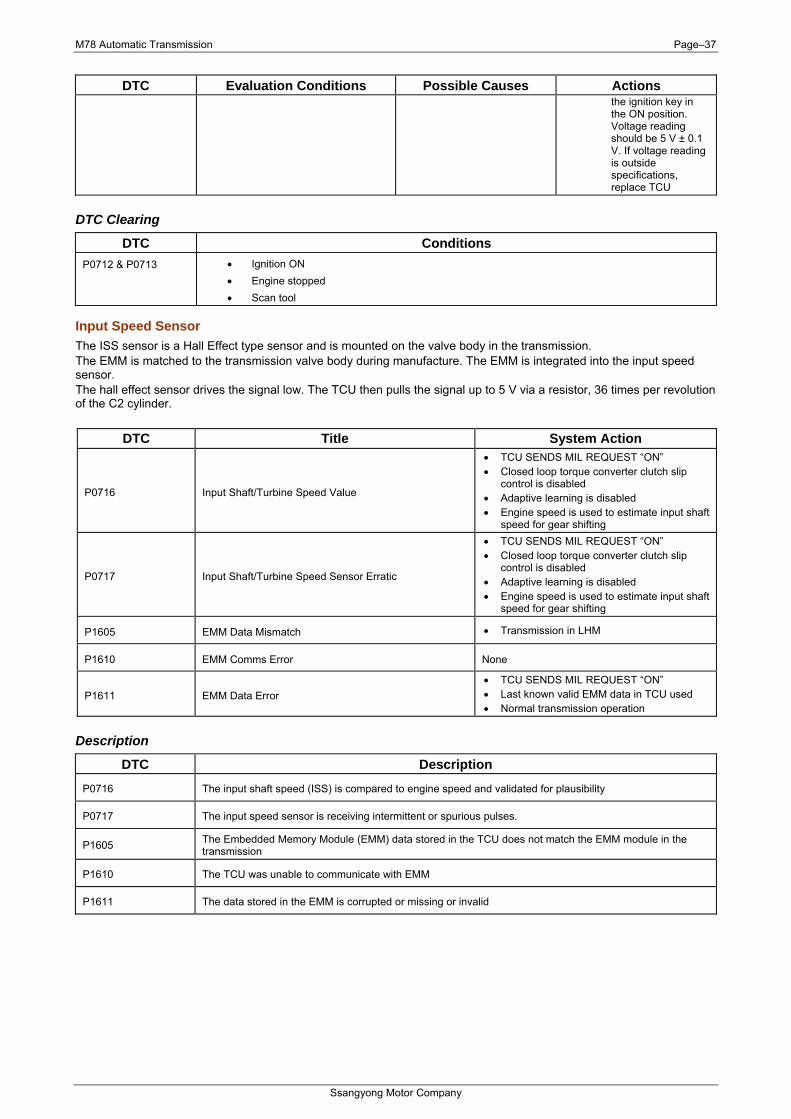
Input Speed Sensor The ISS sensor is a Hall Effect type sensor and is mounted on the valve body in the transmission. The EMM is matched to the transmission valve body during manufacture. The EMM is integrated into the input speed sensor. The hall effect sensor drives the signal low. The TCU then pulls the signal up to 5 V via a resistor, 36 times per revolution of the C2 cylinder.
DTC Title System Action
P0716 Input Shaft/Turbine Speed Value
• TCU SENDS MIL REQUEST “ON” • Closed loop torque converter clutch slip
control is disabled • Adaptive learning is disabled • Engine speed is used to estimate input shaft
speed for gear shifting
P0717 Input Shaft/Turbine Speed Sensor Erratic
• TCU SENDS MIL REQUEST “ON” • Closed loop torque converter clutch slip
control is disabled • Adaptive learning is disabled • Engine speed is used to estimate input shaft
speed for gear shifting
P1605 EMM Data Mismatch • Transmission in LHM
P1610 EMM Comms Error None
P1611 EMM Data Error • TCU SENDS MIL REQUEST “ON” • Last known valid EMM data in TCU used • Normal transmission operation
Description
DTC Description
P0716 The input shaft speed (ISS) is compared to engine speed and validated for plausibility
P0717 The input speed sensor is receiving intermittent or spurious pulses.
P1605 The Embedded Memory Module (EMM) data stored in the TCU does not match the EMM module in the transmission
P1610 The TCU was unable to communicate with EMM
P1611 The data stored in the EMM is corrupted or missing or invalid
M78 Automatic Transmission Page–38
Ssangyong Motor Company
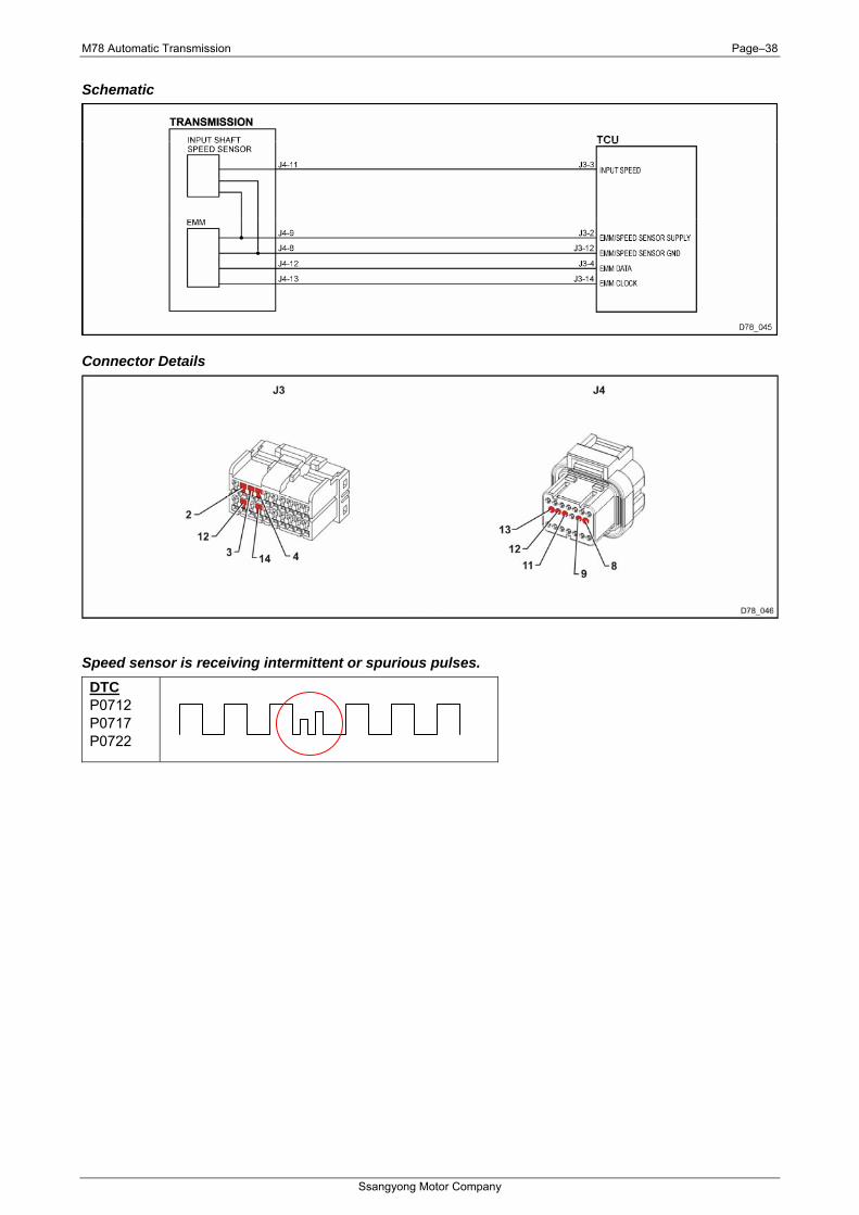
Schematic
Connector Details
Speed sensor is receiving intermittent or spurious pulses. DTC P0712 P0717 P0722
M78 Automatic Transmission Page–39
Ssangyong Motor Company
DTC Details
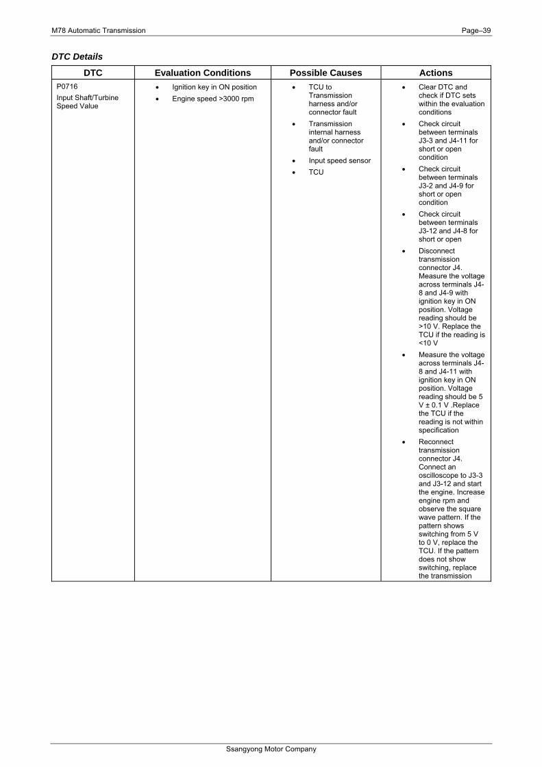
DTC Evaluation Conditions Possible Causes Actions P0716 Input Shaft/Turbine Speed Value
• Ignition key in ON position • Engine speed >3000 rpm
• TCU to Transmission harness and/or connector fault
• Transmission internal harness and/or connector fault
• Input speed sensor • TCU
• Clear DTC and check if DTC sets within the evaluation conditions
• Check circuit between terminals J3-3 and J4-11 for short or open condition
• Check circuit between terminals J3-2 and J4-9 for short or open condition
• Check circuit between terminals J3-12 and J4-8 for short or open
• Disconnect transmission connector J4. Measure the voltage across terminals J4-8 and J4-9 with ignition key in ON position. Voltage reading should be >10 V. Replace the TCU if the reading is <10 V
• Measure the voltage across terminals J4-8 and J4-11 with ignition key in ON position. Voltage reading should be 5 V ± 0.1 V .Replace the TCU if the reading is not within specification
• Reconnect transmission connector J4. Connect an oscilloscope to J3-3 and J3-12 and start the engine. Increase engine rpm and observe the square wave pattern. If the pattern shows switching from 5 V to 0 V, replace the TCU. If the pattern does not show switching, replace the transmission
M78 Automatic Transmission Page–40
Ssangyong Motor Company
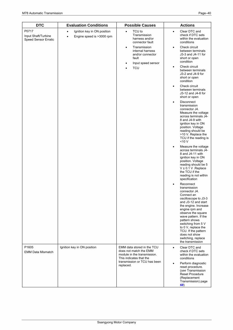
DTC Evaluation Conditions Possible Causes Actions P0717 Input Shaft/Turbine Speed Sensor Erratic
• Ignition key in ON position • Engine speed is >3000 rpm
• TCU to Transmission harness and/or connector fault
• Transmission internal harness and/or connector fault
• Input speed sensor • TCU
• Clear DTC and check if DTC sets within the evaluation conditions
• Check circuit between terminals J3-3 and J4-11 for short or open condition
• Check circuit between terminals J3-2 and J4-9 for short or open condition
• Check circuit between terminals J3-12 and J4-8 for short or open
• Disconnect transmission connector J4. Measure the voltage across terminals J4-8 and J4-9 with ignition key in ON position. Voltage reading should be >10 V. Replace the TCU if the reading is <10 V
• Measure the voltage across terminals J4-8 and J4-11 with ignition key in ON position. Voltage reading should be 5 V ± 0.1 V .Replace the TCU if the reading is not within specification
• Reconnect transmission connector J4. Connect an oscilloscope to J3-3 and J3-12 and start the engine. Increase engine rpm and observe the square wave pattern. If the pattern shows switching from 5 V to 0 V, replace the TCU. If the pattern does not show switching, replace the transmission
P1605 EMM Data Mismatch
Ignition key in ON position EMM data stored in the TCU does not match the EMM module in the transmission. This indicates that the transmission or TCU has been replaced.
• Clear DTC and check if DTC sets within the evaluation conditions
• Perform diagnostic reset procedure. (see Transmission Reset Procedure (Replacement Transmission) page 68)
M78 Automatic Transmission Page–41
Ssangyong Motor Company
DTC Evaluation Conditions Possible Causes Actions P1610 EMM Comms Error
Ignition key in ON position • TCU to Transmission harness and/or connector fault
• Transmission internal harness and/or connector fault
• Input Shaft Speed Sensor
• TCU
• Clear DTC and check if DTC sets within the evaluation conditions
• Check circuit between terminals J3-2 and J4-9 for short or open condition
• Check circuit between terminals J3-12 and J4-8 for short or open
• Check circuit between terminals J3-4 and J4-12 for short or open condition
• Check circuit between terminals J3-14 and J4-13 for short or open condition
• Replace the transmission
P1611 EMM Data Error
Ignition key in ON position • Input Shaft Speed Sensor
• Clear DTC and check if DTC sets within the evaluation conditions
• Replace the transmission
DTC Clearing
DTC Conditions P0716, P0717, P1605, P1610 & P1611
• Ignition ON • Engine stopped • Scan tool
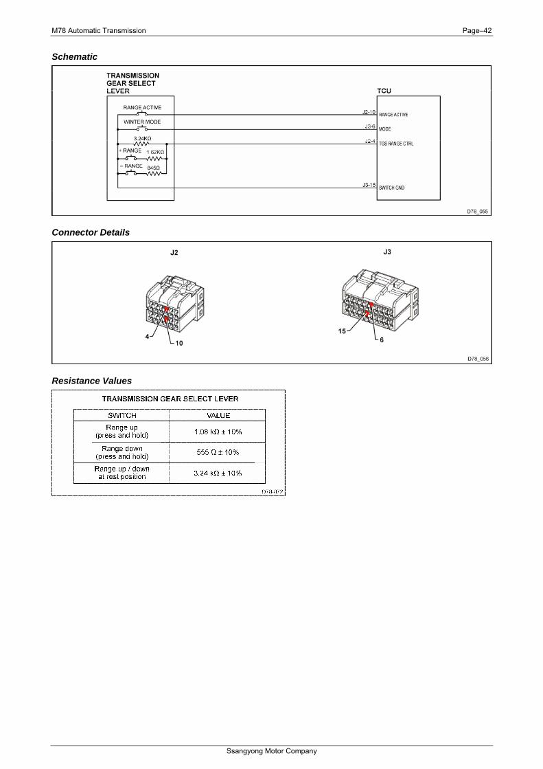
Transmission Gear Select Lever The transmission gear select lever contains the mode switch, manual mode active switch and up/down switches. These switches are connected directly to the TCU.
DTC Title System Action
P071D Manual Shift Control Up/Down (TGS) Switch Stuck • Manual shift control (TGS) switches disabled
P071E Manual Shift Control Up/Down (TGS) Switch Signal Low • Manual shift control (TGS) switches disabled
P071F Manual Shift Control Up/Down (TGS) Switch Signal High • Manual shift control (TGS) switches disabled
Description
DTC Description
DTC P071D The Manual Shift Control Up/Down switch (TGS) has been depressed for more than 120 seconds continuously. This may indicate a faulty switch
DTC P071E The Manual Shift Control Up/Down (TGS) switch signal is giving a value indicative of a short circuit
DTC P071F The Manual Shift Control Up/Down (TGS) switch signal is giving a value indicative of an open circuit
M78 Automatic Transmission Page–42
Ssangyong Motor Company
Schematic
Connector Details
Resistance Values
M78 Automatic Transmission Page–43
Ssangyong Motor Company
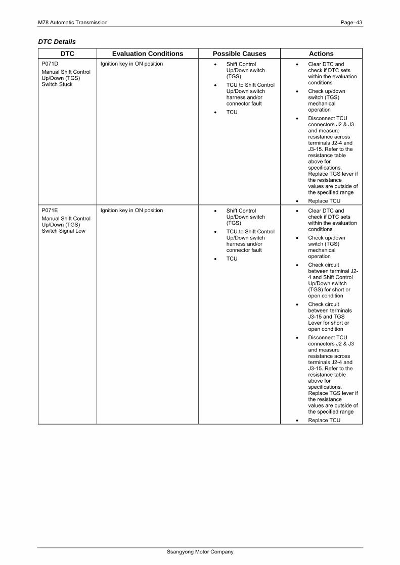
DTC Details
DTC Evaluation Conditions Possible Causes Actions P071D Manual Shift Control Up/Down (TGS) Switch Stuck
Ignition key in ON position • Shift Control Up/Down switch (TGS)
• TCU to Shift Control Up/Down switch harness and/or connector fault
• TCU
• Clear DTC and check if DTC sets within the evaluation conditions
• Check up/down switch (TGS) mechanical operation
• Disconnect TCU connectors J2 & J3 and measure resistance across terminals J2-4 and J3-15. Refer to the resistance table above for specifications. Replace TGS lever if the resistance values are outside of the specified range
• Replace TCU
P071E Manual Shift Control Up/Down (TGS) Switch Signal Low
Ignition key in ON position • Shift Control Up/Down switch (TGS)
• TCU to Shift Control Up/Down switch harness and/or connector fault
• TCU
• Clear DTC and check if DTC sets within the evaluation conditions
• Check up/down switch (TGS) mechanical operation
• Check circuit between terminal J2-4 and Shift Control Up/Down switch (TGS) for short or open condition
• Check circuit between terminals J3-15 and TGS Lever for short or open condition
• Disconnect TCU connectors J2 & J3 and measure resistance across terminals J2-4 and J3-15. Refer to the resistance table above for specifications. Replace TGS lever if the resistance values are outside of the specified range
• Replace TCU
M78 Automatic Transmission Page–44
Ssangyong Motor Company
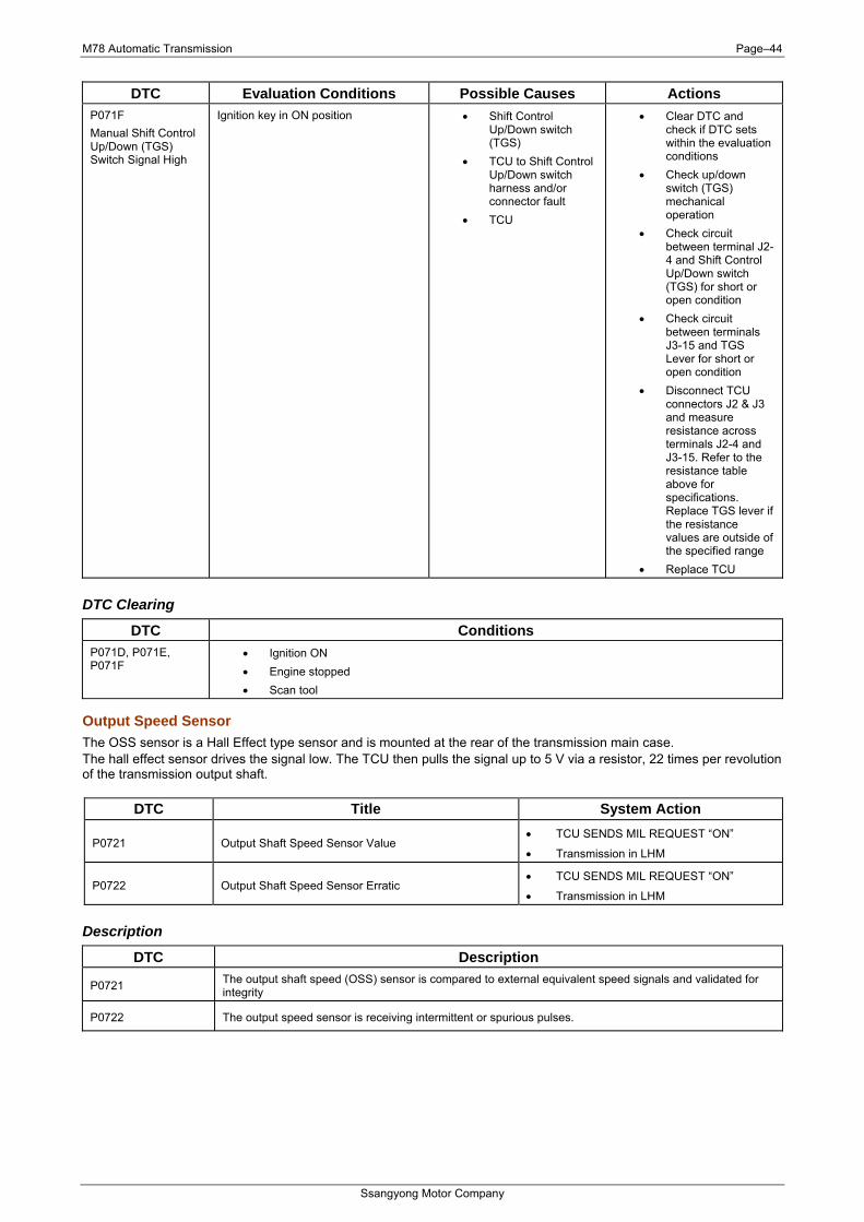
DTC Evaluation Conditions Possible Causes Actions P071F Manual Shift Control Up/Down (TGS) Switch Signal High
Ignition key in ON position • Shift Control Up/Down switch (TGS)
• TCU to Shift Control Up/Down switch harness and/or connector fault
• TCU
• Clear DTC and check if DTC sets within the evaluation conditions
• Check up/down switch (TGS) mechanical operation
• Check circuit between terminal J2-4 and Shift Control Up/Down switch (TGS) for short or open condition
• Check circuit between terminals J3-15 and TGS Lever for short or open condition
• Disconnect TCU connectors J2 & J3 and measure resistance across terminals J2-4 and J3-15. Refer to the resistance table above for specifications. Replace TGS lever if the resistance values are outside of the specified range
• Replace TCU
DTC Clearing
DTC Conditions P071D, P071E, P071F
• Ignition ON • Engine stopped • Scan tool
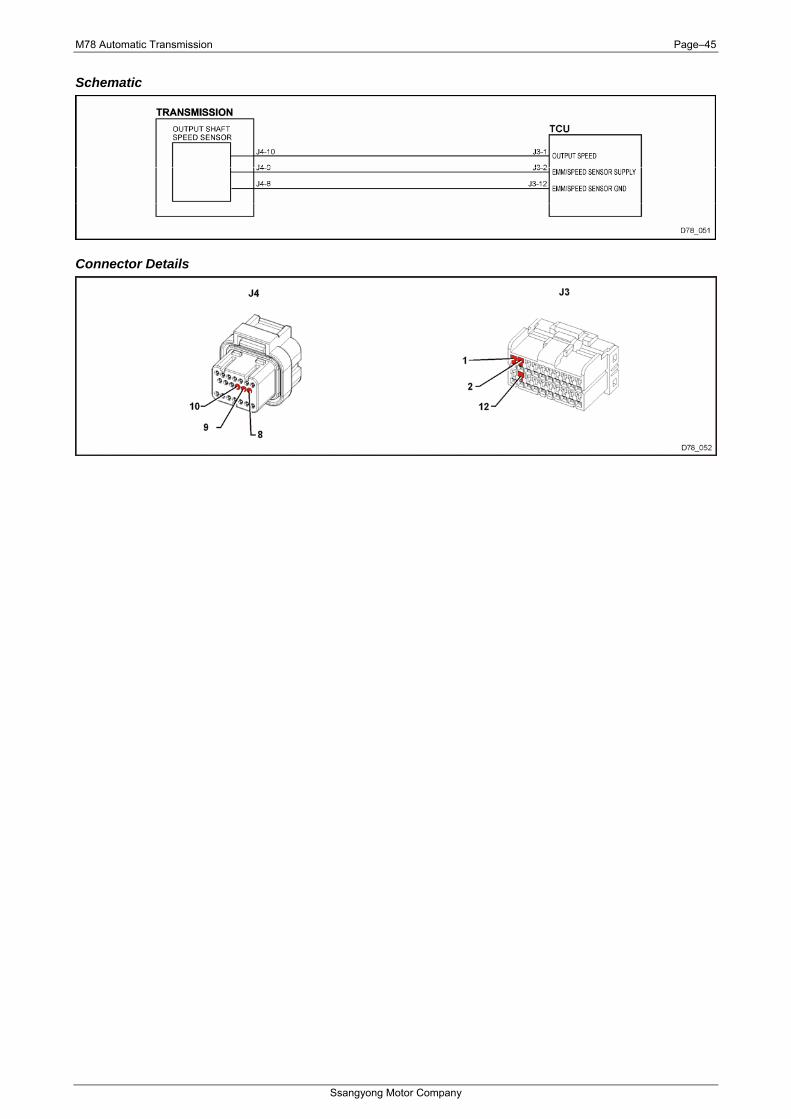
Output Speed Sensor The OSS sensor is a Hall Effect type sensor and is mounted at the rear of the transmission main case. The hall effect sensor drives the signal low. The TCU then pulls the signal up to 5 V via a resistor, 22 times per revolution of the transmission output shaft.
DTC Title System Action
P0721 Output Shaft Speed Sensor Value • TCU SENDS MIL REQUEST “ON”
• Transmission in LHM
P0722 Output Shaft Speed Sensor Erratic • TCU SENDS MIL REQUEST “ON”
• Transmission in LHM
Description
DTC Description
P0721 The output shaft speed (OSS) sensor is compared to external equivalent speed signals and validated for integrity
P0722 The output speed sensor is receiving intermittent or spurious pulses.
M78 Automatic Transmission Page–45
Ssangyong Motor Company
Schematic
Connector Details
M78 Automatic Transmission Page–46
Ssangyong Motor Company
DTC Details
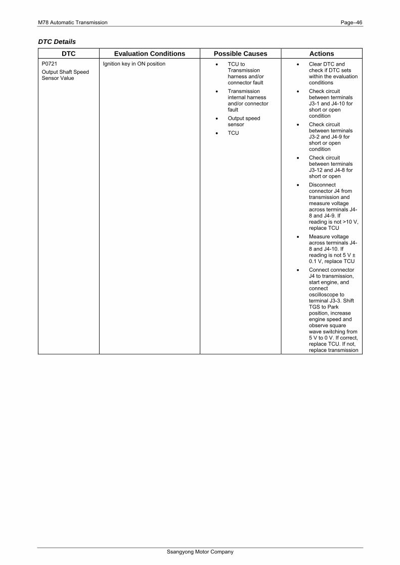
DTC Evaluation Conditions Possible Causes Actions P0721 Output Shaft Speed Sensor Value
Ignition key in ON position • TCU to Transmission harness and/or connector fault
• Transmission internal harness and/or connector fault
• Output speed sensor
• TCU
• Clear DTC and check if DTC sets within the evaluation conditions
• Check circuit between terminals J3-1 and J4-10 for short or open condition
• Check circuit between terminals J3-2 and J4-9 for short or open condition
• Check circuit between terminals J3-12 and J4-8 for short or open
• Disconnect connector J4 from transmission and measure voltage across terminals J4-8 and J4-9. If reading is not >10 V, replace TCU
• Measure voltage across terminals J4-8 and J4-10. If reading is not 5 V ± 0.1 V, replace TCU
• Connect connector J4 to transmission, start engine, and connect oscilloscope to terminal J3-3. Shift TGS to Park position, increase engine speed and observe square wave switching from 5 V to 0 V. If correct, replace TCU. If not, replace transmission
M78 Automatic Transmission Page–47
Ssangyong Motor Company
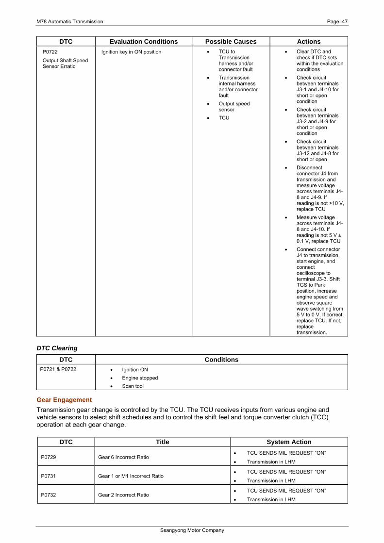
DTC Evaluation Conditions Possible Causes Actions P0722 Output Shaft Speed Sensor Erratic
Ignition key in ON position • TCU to Transmission harness and/or connector fault
• Transmission internal harness and/or connector fault
• Output speed sensor
• TCU
• Clear DTC and check if DTC sets within the evaluation conditions
• Check circuit between terminals J3-1 and J4-10 for short or open condition
• Check circuit between terminals J3-2 and J4-9 for short or open condition
• Check circuit between terminals J3-12 and J4-8 for short or open
• Disconnect connector J4 from transmission and measure voltage across terminals J4-8 and J4-9. If reading is not >10 V, replace TCU
• Measure voltage across terminals J4-8 and J4-10. If reading is not 5 V ± 0.1 V, replace TCU
• Connect connector J4 to transmission, start engine, and connect oscilloscope to terminal J3-3. Shift TGS to Park position, increase engine speed and observe square wave switching from 5 V to 0 V. If correct, replace TCU. If not, replace transmission.
DTC Clearing
DTC Conditions P0721 & P0722 • Ignition ON
• Engine stopped • Scan tool
Gear Engagement Transmission gear change is controlled by the TCU. The TCU receives inputs from various engine and vehicle sensors to select shift schedules and to control the shift feel and torque converter clutch (TCC) operation at each gear change.
DTC Title System Action
P0729 Gear 6 Incorrect Ratio • TCU SENDS MIL REQUEST “ON”
• Transmission in LHM
P0731 Gear 1 or M1 Incorrect Ratio • TCU SENDS MIL REQUEST “ON”
• Transmission in LHM
P0732 Gear 2 Incorrect Ratio • TCU SENDS MIL REQUEST “ON”
• Transmission in LHM
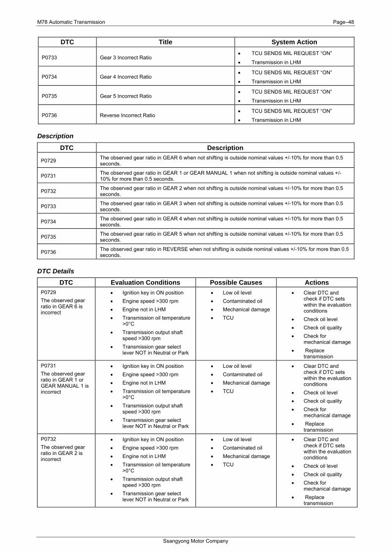
M78 Automatic Transmission Page–48
Ssangyong Motor Company
DTC Title System Action
P0733 Gear 3 Incorrect Ratio • TCU SENDS MIL REQUEST “ON”
• Transmission in LHM
P0734 Gear 4 Incorrect Ratio • TCU SENDS MIL REQUEST “ON”
• Transmission in LHM
P0735 Gear 5 Incorrect Ratio • TCU SENDS MIL REQUEST “ON”
• Transmission in LHM
P0736 Reverse Incorrect Ratio • TCU SENDS MIL REQUEST “ON”
• Transmission in LHM
Description
DTC Description
P0729 The observed gear ratio in GEAR 6 when not shifting is outside nominal values +/-10% for more than 0.5 seconds.
P0731 The observed gear ratio in GEAR 1 or GEAR MANUAL 1 when not shifting is outside nominal values +/-10% for more than 0.5 seconds.
P0732 The observed gear ratio in GEAR 2 when not shifting is outside nominal values +/-10% for more than 0.5 seconds.
P0733 The observed gear ratio in GEAR 3 when not shifting is outside nominal values +/-10% for more than 0.5 seconds.
P0734 The observed gear ratio in GEAR 4 when not shifting is outside nominal values +/-10% for more than 0.5 seconds.
P0735 The observed gear ratio in GEAR 5 when not shifting is outside nominal values +/-10% for more than 0.5 seconds.
P0736 The observed gear ratio in REVERSE when not shifting is outside nominal values +/-10% for more than 0.5 seconds.
DTC Details DTC Evaluation Conditions Possible Causes Actions
P0729 The observed gear ratio in GEAR 6 is incorrect
• Ignition key in ON position • Engine speed >300 rpm • Engine not in LHM • Transmission oil temperature
>0°C • Transmission output shaft
speed >300 rpm • Transmission gear select
lever NOT in Neutral or Park
• Low oil level • Contaminated oil • Mechanical damage • TCU
• Clear DTC and check if DTC sets within the evaluation conditions
• Check oil level • Check oil quality • Check for
mechanical damage • Replace
transmission
P0731 The observed gear ratio in GEAR 1 or GEAR MANUAL 1 is incorrect
• Ignition key in ON position • Engine speed >300 rpm • Engine not in LHM • Transmission oil temperature
>0°C • Transmission output shaft
speed >300 rpm • Transmission gear select
lever NOT in Neutral or Park
• Low oil level • Contaminated oil • Mechanical damage • TCU
• Clear DTC and check if DTC sets within the evaluation conditions
• Check oil level • Check oil quality • Check for
mechanical damage • Replace
transmission
P0732 The observed gear ratio in GEAR 2 is incorrect
• Ignition key in ON position • Engine speed >300 rpm • Engine not in LHM • Transmission oil temperature
>0°C • Transmission output shaft
speed >300 rpm • Transmission gear select
lever NOT in Neutral or Park
• Low oil level • Contaminated oil • Mechanical damage • TCU
• Clear DTC and check if DTC sets within the evaluation conditions
• Check oil level • Check oil quality • Check for
mechanical damage • Replace
transmission
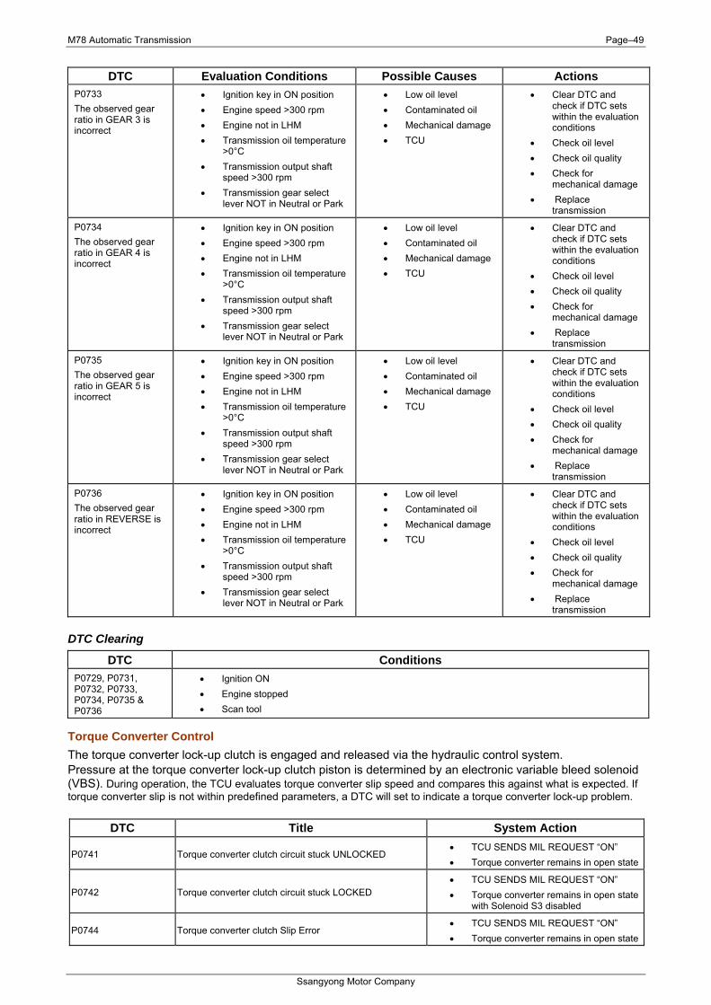
M78 Automatic Transmission Page–49
Ssangyong Motor Company
DTC Evaluation Conditions Possible Causes Actions P0733 The observed gear ratio in GEAR 3 is incorrect
• Ignition key in ON position • Engine speed >300 rpm • Engine not in LHM • Transmission oil temperature
>0°C • Transmission output shaft
speed >300 rpm • Transmission gear select
lever NOT in Neutral or Park
• Low oil level • Contaminated oil • Mechanical damage • TCU
• Clear DTC and check if DTC sets within the evaluation conditions
• Check oil level • Check oil quality • Check for
mechanical damage • Replace
transmission
P0734 The observed gear ratio in GEAR 4 is incorrect
• Ignition key in ON position • Engine speed >300 rpm • Engine not in LHM • Transmission oil temperature
>0°C • Transmission output shaft
speed >300 rpm • Transmission gear select
lever NOT in Neutral or Park
• Low oil level • Contaminated oil • Mechanical damage • TCU
• Clear DTC and check if DTC sets within the evaluation conditions
• Check oil level • Check oil quality • Check for
mechanical damage • Replace
transmission
P0735 The observed gear ratio in GEAR 5 is incorrect
• Ignition key in ON position • Engine speed >300 rpm • Engine not in LHM • Transmission oil temperature
>0°C • Transmission output shaft
speed >300 rpm • Transmission gear select
lever NOT in Neutral or Park
• Low oil level • Contaminated oil • Mechanical damage • TCU
• Clear DTC and check if DTC sets within the evaluation conditions
• Check oil level • Check oil quality • Check for
mechanical damage • Replace
transmission
P0736 The observed gear ratio in REVERSE is incorrect
• Ignition key in ON position • Engine speed >300 rpm • Engine not in LHM • Transmission oil temperature
>0°C • Transmission output shaft
speed >300 rpm • Transmission gear select
lever NOT in Neutral or Park
• Low oil level • Contaminated oil • Mechanical damage • TCU
• Clear DTC and check if DTC sets within the evaluation conditions
• Check oil level • Check oil quality • Check for
mechanical damage • Replace
transmission
DTC Clearing
DTC Conditions P0729, P0731, P0732, P0733, P0734, P0735 & P0736
• Ignition ON • Engine stopped • Scan tool
Torque Converter Control The torque converter lock-up clutch is engaged and released via the hydraulic control system. Pressure at the torque converter lock-up clutch piston is determined by an electronic variable bleed solenoid (VBS). During operation, the TCU evaluates torque converter slip speed and compares this against what is expected. If torque converter slip is not within predefined parameters, a DTC will set to indicate a torque converter lock-up problem.
DTC Title System Action
P0741 Torque converter clutch circuit stuck UNLOCKED • TCU SENDS MIL REQUEST “ON” • Torque converter remains in open state
P0742 Torque converter clutch circuit stuck LOCKED • TCU SENDS MIL REQUEST “ON” • Torque converter remains in open state
with Solenoid S3 disabled
P0744 Torque converter clutch Slip Error • TCU SENDS MIL REQUEST “ON” • Torque converter remains in open state
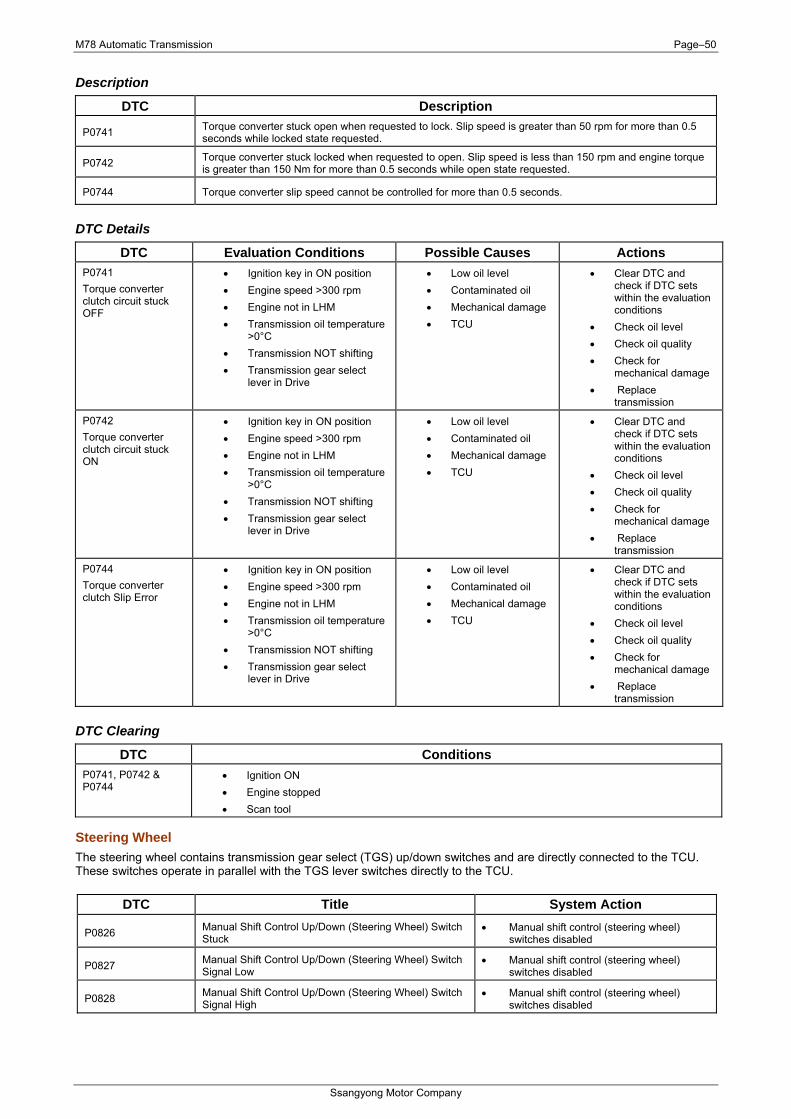
M78 Automatic Transmission Page–50
Ssangyong Motor Company
Description
DTC Description
P0741 Torque converter stuck open when requested to lock. Slip speed is greater than 50 rpm for more than 0.5 seconds while locked state requested.
P0742 Torque converter stuck locked when requested to open. Slip speed is less than 150 rpm and engine torque is greater than 150 Nm for more than 0.5 seconds while open state requested.
P0744 Torque converter slip speed cannot be controlled for more than 0.5 seconds.
DTC Details
DTC Evaluation Conditions Possible Causes Actions P0741 Torque converter clutch circuit stuck OFF
• Ignition key in ON position • Engine speed >300 rpm • Engine not in LHM • Transmission oil temperature
>0°C • Transmission NOT shifting • Transmission gear select
lever in Drive
• Low oil level • Contaminated oil • Mechanical damage • TCU
• Clear DTC and check if DTC sets within the evaluation conditions
• Check oil level • Check oil quality • Check for
mechanical damage • Replace
transmission
P0742 Torque converter clutch circuit stuck ON
• Ignition key in ON position • Engine speed >300 rpm • Engine not in LHM • Transmission oil temperature
>0°C • Transmission NOT shifting • Transmission gear select
lever in Drive
• Low oil level • Contaminated oil • Mechanical damage • TCU
• Clear DTC and check if DTC sets within the evaluation conditions
• Check oil level • Check oil quality • Check for
mechanical damage • Replace
transmission
P0744 Torque converter clutch Slip Error
• Ignition key in ON position • Engine speed >300 rpm • Engine not in LHM • Transmission oil temperature
>0°C • Transmission NOT shifting • Transmission gear select
lever in Drive
• Low oil level • Contaminated oil • Mechanical damage • TCU
• Clear DTC and check if DTC sets within the evaluation conditions
• Check oil level • Check oil quality • Check for
mechanical damage • Replace
transmission
DTC Clearing
DTC Conditions P0741, P0742 & P0744
• Ignition ON • Engine stopped • Scan tool
Steering Wheel The steering wheel contains transmission gear select (TGS) up/down switches and are directly connected to the TCU. These switches operate in parallel with the TGS lever switches directly to the TCU.
DTC Title System Action
P0826 Manual Shift Control Up/Down (Steering Wheel) Switch Stuck
• Manual shift control (steering wheel) switches disabled
P0827 Manual Shift Control Up/Down (Steering Wheel) Switch Signal Low
• Manual shift control (steering wheel) switches disabled
P0828 Manual Shift Control Up/Down (Steering Wheel) Switch Signal High
• Manual shift control (steering wheel) switches disabled
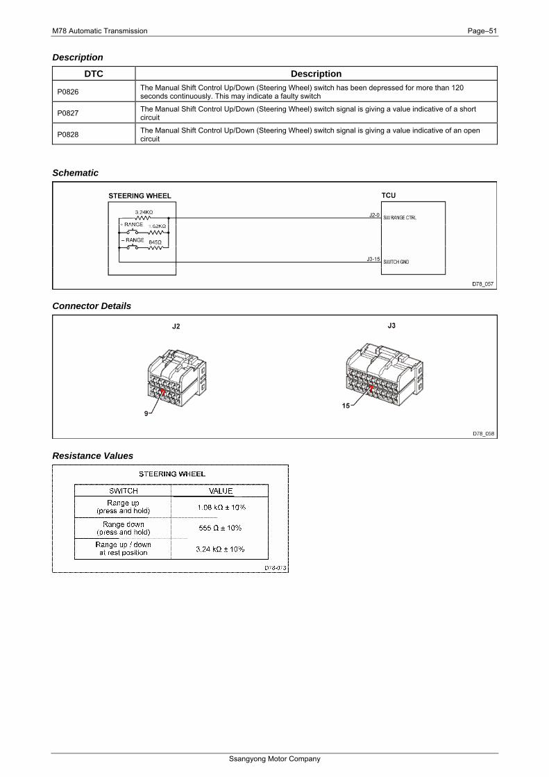
M78 Automatic Transmission Page–51
Ssangyong Motor Company
Description
DTC Description
P0826 The Manual Shift Control Up/Down (Steering Wheel) switch has been depressed for more than 120 seconds continuously. This may indicate a faulty switch
P0827 The Manual Shift Control Up/Down (Steering Wheel) switch signal is giving a value indicative of a short circuit
P0828 The Manual Shift Control Up/Down (Steering Wheel) switch signal is giving a value indicative of an open circuit
Schematic
Connector Details
Resistance Values
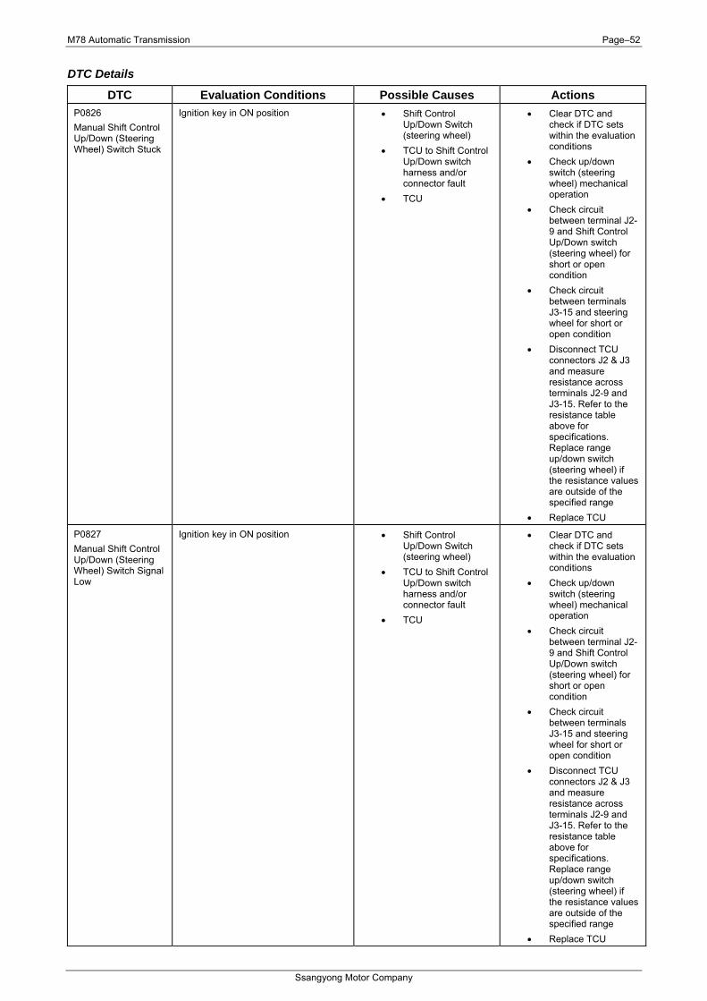
M78 Automatic Transmission Page–52
Ssangyong Motor Company
DTC Details
DTC Evaluation Conditions Possible Causes Actions P0826 Manual Shift Control Up/Down (Steering Wheel) Switch Stuck
Ignition key in ON position • Shift Control Up/Down Switch (steering wheel)
• TCU to Shift Control Up/Down switch harness and/or connector fault
• TCU
• Clear DTC and check if DTC sets within the evaluation conditions
• Check up/down switch (steering wheel) mechanical operation
• Check circuit between terminal J2-9 and Shift Control Up/Down switch (steering wheel) for short or open condition
• Check circuit between terminals J3-15 and steering wheel for short or open condition
• Disconnect TCU connectors J2 & J3 and measure resistance across terminals J2-9 and J3-15. Refer to the resistance table above for specifications. Replace range up/down switch (steering wheel) if the resistance values are outside of the specified range
• Replace TCU
P0827 Manual Shift Control Up/Down (Steering Wheel) Switch Signal Low
Ignition key in ON position • Shift Control Up/Down Switch (steering wheel)
• TCU to Shift Control Up/Down switch harness and/or connector fault
• TCU
• Clear DTC and check if DTC sets within the evaluation conditions
• Check up/down switch (steering wheel) mechanical operation
• Check circuit between terminal J2-9 and Shift Control Up/Down switch (steering wheel) for short or open condition
• Check circuit between terminals J3-15 and steering wheel for short or open condition
• Disconnect TCU connectors J2 & J3 and measure resistance across terminals J2-9 and J3-15. Refer to the resistance table above for specifications. Replace range up/down switch (steering wheel) if the resistance values are outside of the specified range
• Replace TCU
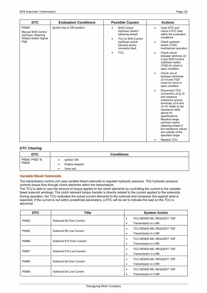
M78 Automatic Transmission Page–53
Ssangyong Motor Company
DTC Evaluation Conditions Possible Causes Actions P0828 Manual Shift Control Up/Down (Steering Wheel) Switch Signal High
Ignition key in ON position • Shift Control Up/Down Switch (steering wheel)
• TCU to Shift Control Up/Down switch harness and/or connector fault
• TCU
• Clear DTC and check if DTC sets within the evaluation conditions
• Check up/down switch (TGS) mechanical operation
• Check circuit between terminal J2-4 and Shift Control Up/Down switch (TGS) for short or open condition
• Check circuit between terminals J3-15 and TGS Lever for short or open condition
• Disconnect TCU connectors J2 & J3 and measure resistance across terminals J2-9 and J3-15. Refer to the resistance table above for specifications. Replace range up/down switch (steering wheel) if the resistance values are outside of the specified range
• Replace TCU
DTC Clearing
DTC Conditions P0826, P0827 & P0828
• Ignition ON • Engine stopped • Scan tool
Variable Bleed Solenoids The transmission control unit uses variable bleed solenoids to regulate hydraulic pressure. This hydraulic pressure controls torque flow through clutch elements within the transmission. The TCU is able to vary the amount of torque applied to the clutch elements by controlling the current to the variable bleed solenoid windings. The clutch element torque transfer is directly related to the current applied to the solenoids. During operation, the TCU evaluates the actual current delivered to the solenoid and compares this against what is expected. If the current is not within predefined parameters, a DTC will be set to indicate the load on the TCU is abnormal.
DTC Title System Action
P0962 Solenoid S9 Over Current • TCU SENDS MIL REQUEST “ON”
• Transmission in LHM
P0963 Solenoid S9 Low Current • TCU SENDS MIL REQUEST “ON”
• Transmission in LHM
P0966 Solenoid S10 Over Current • TCU SENDS MIL REQUEST “ON”
• Transmission in LHM
P0967 Solenoid S10 Low Current • TCU SENDS MIL REQUEST “ON”
• Transmission in LHM
P0985 Solenoid S5 Over Current • TCU SENDS MIL REQUEST “ON”
• Transmission in LHM
P0986 Solenoid S5 Low Current • TCU SENDS MIL REQUEST “ON”
• Transmission in LHM
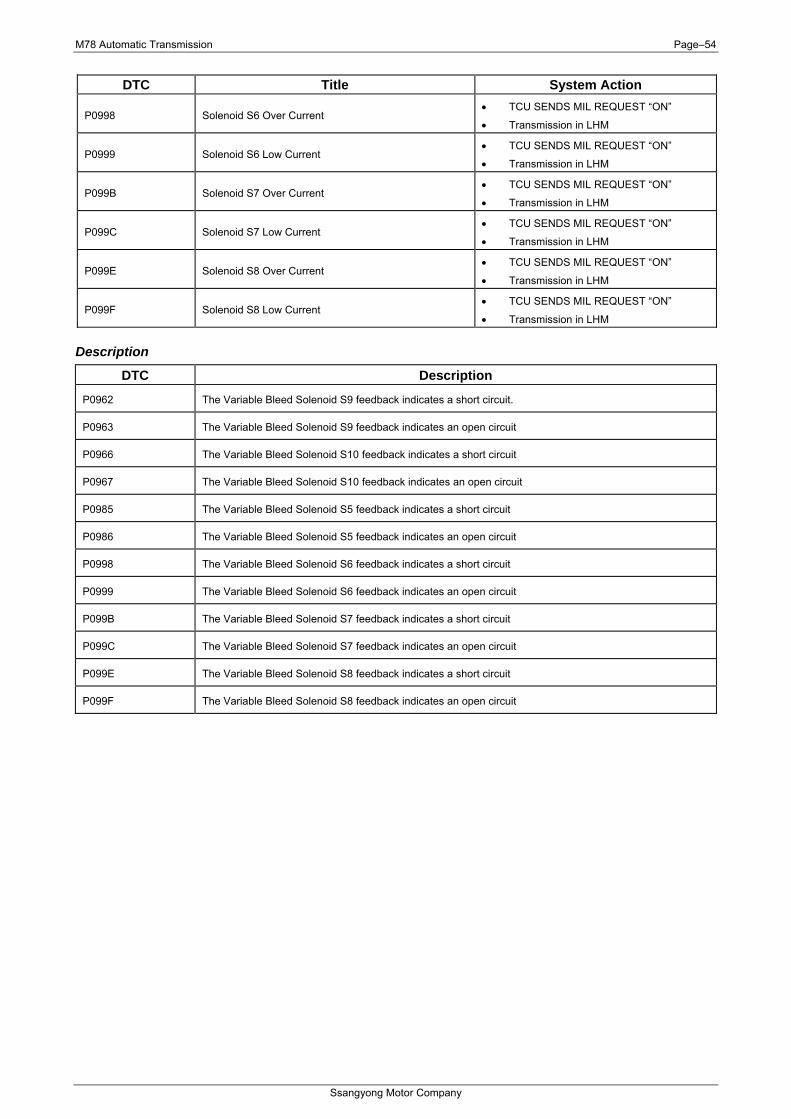
M78 Automatic Transmission Page–54
Ssangyong Motor Company
DTC Title System Action
P0998 Solenoid S6 Over Current • TCU SENDS MIL REQUEST “ON”
• Transmission in LHM
P0999 Solenoid S6 Low Current • TCU SENDS MIL REQUEST “ON”
• Transmission in LHM
P099B Solenoid S7 Over Current • TCU SENDS MIL REQUEST “ON”
• Transmission in LHM
P099C Solenoid S7 Low Current • TCU SENDS MIL REQUEST “ON”
• Transmission in LHM
P099E Solenoid S8 Over Current • TCU SENDS MIL REQUEST “ON”
• Transmission in LHM
P099F Solenoid S8 Low Current • TCU SENDS MIL REQUEST “ON”
• Transmission in LHM
Description
DTC Description
P0962 The Variable Bleed Solenoid S9 feedback indicates a short circuit.
P0963 The Variable Bleed Solenoid S9 feedback indicates an open circuit
P0966 The Variable Bleed Solenoid S10 feedback indicates a short circuit
P0967 The Variable Bleed Solenoid S10 feedback indicates an open circuit
P0985 The Variable Bleed Solenoid S5 feedback indicates a short circuit
P0986 The Variable Bleed Solenoid S5 feedback indicates an open circuit
P0998 The Variable Bleed Solenoid S6 feedback indicates a short circuit
P0999 The Variable Bleed Solenoid S6 feedback indicates an open circuit
P099B The Variable Bleed Solenoid S7 feedback indicates a short circuit
P099C The Variable Bleed Solenoid S7 feedback indicates an open circuit
P099E The Variable Bleed Solenoid S8 feedback indicates a short circuit
P099F The Variable Bleed Solenoid S8 feedback indicates an open circuit
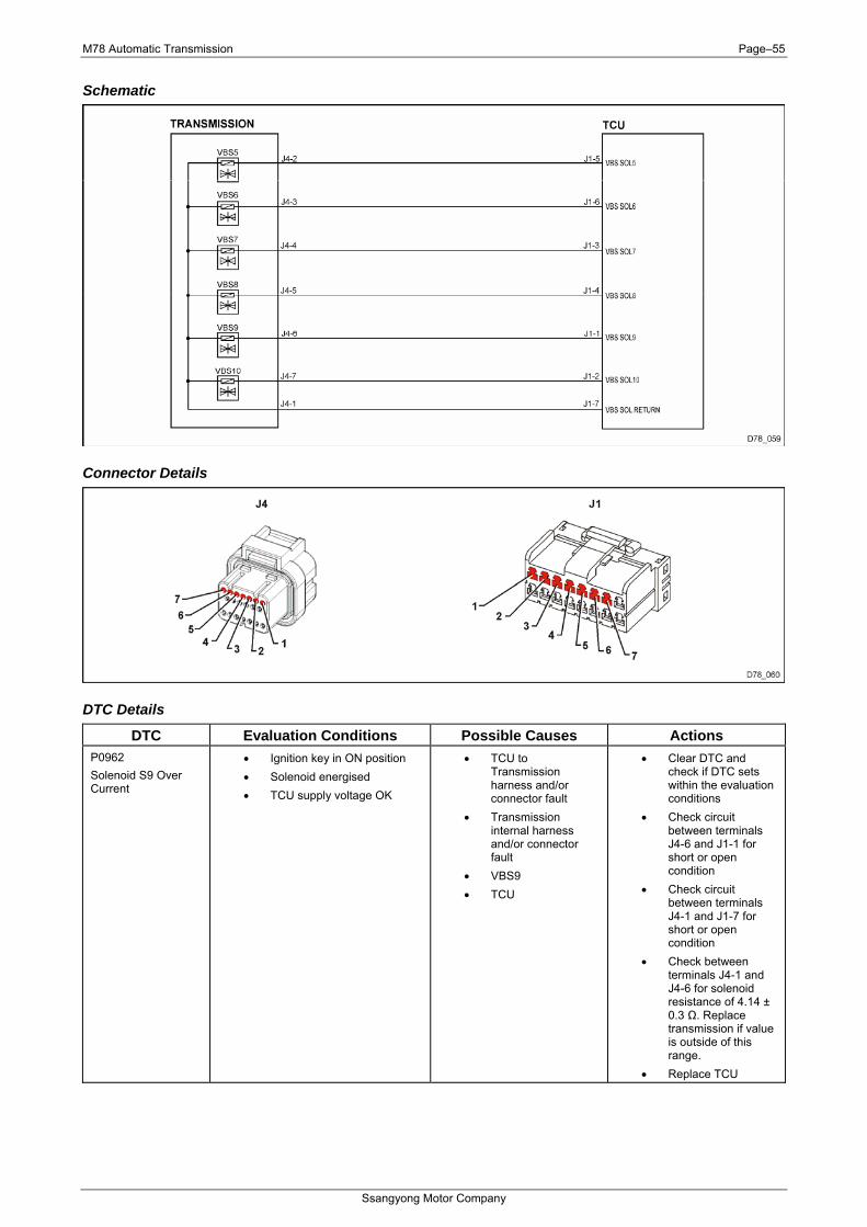
M78 Automatic Transmission Page–55
Ssangyong Motor Company
Schematic
Connector Details
DTC Details
DTC Evaluation Conditions Possible Causes Actions P0962 Solenoid S9 Over Current
• Ignition key in ON position • Solenoid energised • TCU supply voltage OK
• TCU to Transmission harness and/or connector fault
• Transmission internal harness and/or connector fault
• VBS9 • TCU
• Clear DTC and check if DTC sets within the evaluation conditions
• Check circuit between terminals J4-6 and J1-1 for short or open condition
• Check circuit between terminals J4-1 and J1-7 for short or open condition
• Check between terminals J4-1 and J4-6 for solenoid resistance of 4.14 ± 0.3 Ω. Replace transmission if value is outside of this range.
• Replace TCU

M78 Automatic Transmission Page–56
Ssangyong Motor Company
DTC Evaluation Conditions Possible Causes Actions P0963 Solenoid S9 Low Current
• Ignition key in ON position • Solenoid energised • TCU supply voltage OK
• TCU to Transmission harness and/or connector fault
• Transmission internal harness and/or connector fault
• VBS9 • TCU
• Clear DTC and check if DTC sets within the evaluation conditions
• Check circuit between terminals J4-6 and J1-1 for short or open condition
• Check circuit between terminals J4-1 and J1-7 for short or open condition
• Check between terminals J4-1 and J4-6 for solenoid resistance of 4.14 ± 0.3 Ω. Replace transmission if value is outside of this range.
• Replace TCU
P0966 Solenoid S10 Over Current
• Ignition key in ON position • Solenoid energised • TCU supply voltage OK
• TCU to Transmission harness and/or connector fault
• Transmission internal harness and/or connector fault
• VBS10 • TCU
• Clear DTC and check if DTC sets within the evaluation conditions
• Check circuit between terminals J4-7 and J1-2 for short or open condition
• Check circuit between terminals J4-1 and J1-7 for short or open condition
• Check between terminals J4-1 and J4-7 for solenoid resistance of 4.14 ± 0.3 Ω. Replace transmission if value is outside of this range.
• Replace TCU
P0967 Solenoid S10 Low Current
• Ignition key in ON position • Solenoid energised • TCU supply voltage OK
• TCU to Transmission harness and/or connector fault
• Transmission internal harness and/or connector fault
• VBS10 • TCU
• Clear DTC and check if DTC sets within the evaluation conditions
• Check circuit between terminals J4-7 and J1-2 for short or open condition
• Check circuit between terminals J4-1 and J1-7 for short or open condition
• Check between terminals J4-1 and J4-7 for solenoid resistance of 4.14 ± 0.3 Ω. Replace transmission if value is outside of this range.
• Replace TCU

M78 Automatic Transmission Page–57
Ssangyong Motor Company
DTC Evaluation Conditions Possible Causes Actions P0985 Solenoid S5 Over Current
• Ignition key in ON position • Solenoid energised • TCU supply voltage OK
• TCU to Transmission harness and/or connector fault
• Transmission internal harness and/or connector fault
• VBS5 • TCU
• Clear DTC and check if DTC sets within the evaluation conditions
• Check circuit between terminals J4-2 and J1-5 for short or open condition
• Check circuit between terminals J4-1 and J1-7 for short or open condition
• Check between terminals J4-1 and J4-2 for solenoid resistance of 4.14 ± 0.3 Ω. Replace transmission if value is outside of this range.
• Replace TCU
P0986 Solenoid S5 Low Current
• Ignition key in ON position • Solenoid energised • TCU supply voltage OK
• TCU to Transmission harness and/or connector fault
• Transmission internal harness and/or connector fault
• VBS5 • TCU
• Clear DTC and check if DTC sets within the evaluation conditions
• Check circuit between terminals J4-2 and J1-5 for short or open condition
• Check circuit between terminals J4-1 and J1-7 for short or open condition
• Check between terminals J4-1 and J4-2 for solenoid resistance of 4.14 ± 0.3 Ω. Replace transmission if value is outside of this range.
• Replace TCU
P0998 Solenoid S6 Over Current
• Ignition key in ON position • Solenoid energised • TCU supply voltage OK
• TCU to Transmission harness and/or connector fault
• Transmission internal harness and/or connector fault
• VBS6 • TCU
• Clear DTC and check if DTC sets within the evaluation conditions
• Check circuit between terminals J4-3 and J1-6 for short or open condition
• Check circuit between terminals J4-1 and J1-7 for short or open condition
• Check between terminals J4-1 and J4-3 for solenoid resistance of 4.14 ± 0.3 Ω. Replace transmission if value is outside of this range.
• Replace TCU

M78 Automatic Transmission Page–58
Ssangyong Motor Company
DTC Evaluation Conditions Possible Causes Actions P0999 Solenoid S6 Low Current
• Ignition key in ON position • Solenoid energised • TCU supply voltage OK
• TCU to Transmission harness and/or connector fault
• Transmission internal harness and/or connector fault
• VBS6 • TCU
• Clear DTC and check if DTC sets within the evaluation conditions
• Check circuit between terminals J4-3 and J1-6 for short or open condition
• Check circuit between terminals J4-1 and J1-7 for short or open condition
• Check between terminals J4-1 and J4-3 for solenoid resistance of 4.14 ± 0.3 Ω. Replace transmission if value is outside of this range.
• Replace TCU
P099B Solenoid S7 Over Current
• Ignition key in ON position • Solenoid energised • TCU supply voltage OK
• TCU to Transmission harness and/or connector fault
• Transmission internal harness and/or connector fault
• VBS7 • TCU
• Clear DTC and check if DTC sets within the evaluation conditions
• Check circuit between terminals J4-4 and J1-3 for short or open condition
• Check circuit between terminals J4-1 and J1-7 for short or open condition
• Check between terminals J4-1 and J4-4 for solenoid resistance of 4.14 ± 0.3 Ω. Replace transmission if value is outside of this range.
• Replace TCU
P099C Solenoid S7 Low Current
• Ignition key in ON position • Solenoid energised • TCU supply voltage OK
• TCU to Transmission harness and/or connector fault
• Transmission internal harness and/or connector fault
• VBS7 • TCU
• Clear DTC and check if DTC sets within the evaluation conditions
• Check circuit between terminals J4-4 and J1-3 for short or open condition
• Check circuit between terminals J4-1 and J1-7 for short or open condition
• Check between terminals J4-1 and J4-4 for solenoid resistance of 4.14 ± 0.3 Ω. Replace transmission if value is outside of this range.
• Replace TCU
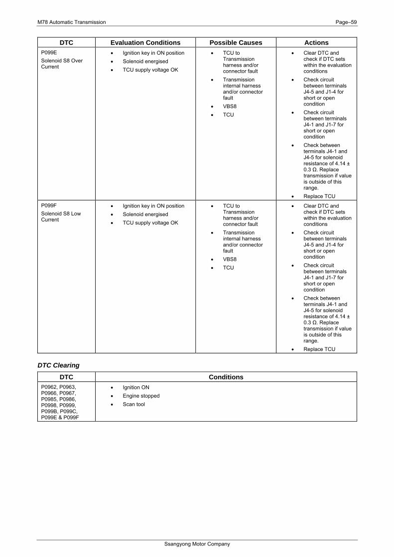
M78 Automatic Transmission Page–59
Ssangyong Motor Company
DTC Evaluation Conditions Possible Causes Actions P099E Solenoid S8 Over Current
• Ignition key in ON position • Solenoid energised • TCU supply voltage OK
• TCU to Transmission harness and/or connector fault
• Transmission internal harness and/or connector fault
• VBS8 • TCU
• Clear DTC and check if DTC sets within the evaluation conditions
• Check circuit between terminals J4-5 and J1-4 for short or open condition
• Check circuit between terminals J4-1 and J1-7 for short or open condition
• Check between terminals J4-1 and J4-5 for solenoid resistance of 4.14 ± 0.3 Ω. Replace transmission if value is outside of this range.
• Replace TCU
P099F Solenoid S8 Low Current
• Ignition key in ON position • Solenoid energised • TCU supply voltage OK
• TCU to Transmission harness and/or connector fault
• Transmission internal harness and/or connector fault
• VBS8 • TCU
• Clear DTC and check if DTC sets within the evaluation conditions
• Check circuit between terminals J4-5 and J1-4 for short or open condition
• Check circuit between terminals J4-1 and J1-7 for short or open condition
• Check between terminals J4-1 and J4-5 for solenoid resistance of 4.14 ± 0.3 Ω. Replace transmission if value is outside of this range.
• Replace TCU
DTC Clearing
DTC Conditions P0962, P0963, P0966, P0967, P0985, P0986, P0998, P0999, P099B, P099C, P099E & P099F
• Ignition ON • Engine stopped • Scan tool
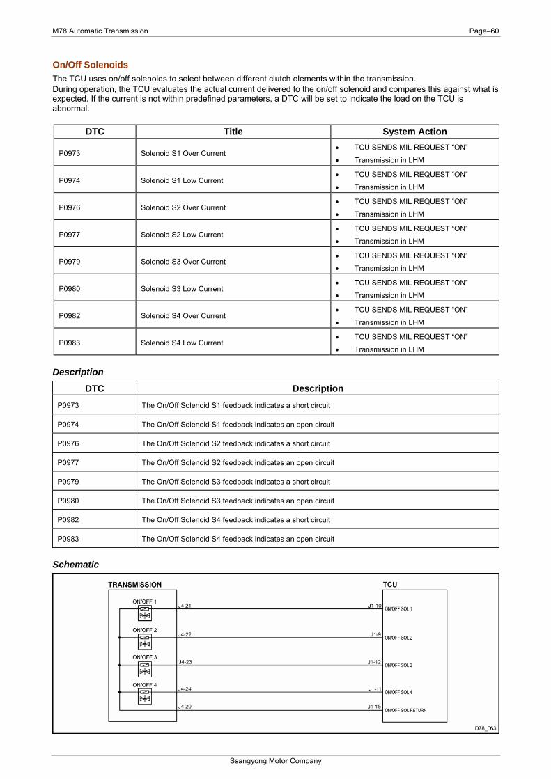
M78 Automatic Transmission Page–60
Ssangyong Motor Company
On/Off Solenoids The TCU uses on/off solenoids to select between different clutch elements within the transmission. During operation, the TCU evaluates the actual current delivered to the on/off solenoid and compares this against what is expected. If the current is not within predefined parameters, a DTC will be set to indicate the load on the TCU is abnormal.
DTC Title System Action
P0973 Solenoid S1 Over Current • TCU SENDS MIL REQUEST “ON”
• Transmission in LHM
P0974 Solenoid S1 Low Current • TCU SENDS MIL REQUEST “ON”
• Transmission in LHM
P0976 Solenoid S2 Over Current • TCU SENDS MIL REQUEST “ON”
• Transmission in LHM
P0977 Solenoid S2 Low Current • TCU SENDS MIL REQUEST “ON”
• Transmission in LHM
P0979 Solenoid S3 Over Current • TCU SENDS MIL REQUEST “ON”
• Transmission in LHM
P0980 Solenoid S3 Low Current • TCU SENDS MIL REQUEST “ON”
• Transmission in LHM
P0982 Solenoid S4 Over Current • TCU SENDS MIL REQUEST “ON”
• Transmission in LHM
P0983 Solenoid S4 Low Current • TCU SENDS MIL REQUEST “ON”
• Transmission in LHM
Description
DTC Description
P0973 The On/Off Solenoid S1 feedback indicates a short circuit
P0974 The On/Off Solenoid S1 feedback indicates an open circuit
P0976 The On/Off Solenoid S2 feedback indicates a short circuit
P0977 The On/Off Solenoid S2 feedback indicates an open circuit
P0979 The On/Off Solenoid S3 feedback indicates a short circuit
P0980 The On/Off Solenoid S3 feedback indicates an open circuit
P0982 The On/Off Solenoid S4 feedback indicates a short circuit
P0983 The On/Off Solenoid S4 feedback indicates an open circuit
Schematic
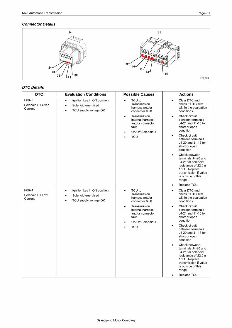
M78 Automatic Transmission Page–61
Ssangyong Motor Company
Connector Details
DTC Details
DTC Evaluation Conditions Possible Causes Actions P0973 Solenoid S1 Over Current
• Ignition key in ON position • Solenoid energised • TCU supply voltage OK
• TCU to Transmission harness and/or connector fault
• Transmission internal harness and/or connector fault
• On/Off Solenoid 1 • TCU
• Clear DTC and check if DTC sets within the evaluation conditions
• Check circuit between terminals J4-21 and J1-10 for short or open condition
• Check circuit between terminals J4-20 and J1-15 for short or open condition
• Check between terminals J4-20 and J4-21 for solenoid resistance of 22.0 ± 1.2 Ω. Replace transmission if value is outside of this range.
• Replace TCU
P0974 Solenoid S1 Low Current
• Ignition key in ON position • Solenoid energised • TCU supply voltage OK
• TCU to Transmission harness and/or connector fault
• Transmission internal harness and/or connector fault
• On/Off Solenoid 1 • TCU
• Clear DTC and check if DTC sets within the evaluation conditions
• Check circuit between terminals J4-21 and J1-10 for short or open condition
• Check circuit between terminals J4-20 and J1-15 for short or open condition
• Check between terminals J4-20 and J4-21 for solenoid resistance of 22.0 ± 1.2 Ω. Replace transmission if value is outside of this range.
• Replace TCU

M78 Automatic Transmission Page–62
Ssangyong Motor Company
DTC Evaluation Conditions Possible Causes Actions P0976 Solenoid S2 Over Current
• Ignition key in ON position • Solenoid energised • TCU supply voltage OK
• TCU to Transmission harness and/or connector fault
• Transmission internal harness and/or connector fault
• On/Off Solenoid 2 • TCU
• Clear DTC and check if DTC sets within the evaluation conditions
• Check circuit between terminals J4-22 and J1-9 for short or open condition
• Check circuit between terminals J4-20 and J1-15 for short or open condition
• Check between terminals J4-20 and J4-22 for solenoid resistance of 22.0 ± 1.2 Ω. Replace transmission if value is outside of this range.
• Replace TCU
P0977 Solenoid S2 Low Current
• Ignition key in ON position • Solenoid energised • TCU supply voltage OK
• TCU to Transmission harness and/or connector fault
• Transmission internal harness and/or connector fault
• On/Off Solenoid 2 • TCU
• Clear DTC and check if DTC sets within the evaluation conditions
• Check circuit between terminals J4-22 and J1-9 for short or open condition
• Check circuit between terminals J4-20 and J1-15 for short or open condition
• Check between terminals J4-20 and J4-22 for solenoid resistance of 22.0 ± 1.2 Ω. Replace transmission if value is outside of this range.
• Replace TCU
P0979 Solenoid S3 Over Current
• Ignition key in ON position • Solenoid energised • TCU supply voltage OK
• TCU to Transmission harness and/or connector fault
• Transmission internal harness and/or connector fault
• On/Off Solenoid 3 • TCU
• Clear DTC and check if DTC sets within the evaluation conditions
• Check circuit between terminals J4-23 and J1-12 for short or open condition
• Check circuit between terminals J4-20 and J1-15 for short or open condition
• Check between terminals J4-20 and J4-23 for solenoid resistance of 22.0 ± 1.2 Ω. Replace transmission if value is outside of this range.
• Replace TCU
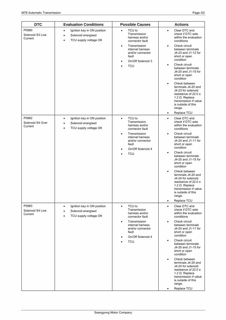
M78 Automatic Transmission Page–63
Ssangyong Motor Company
DTC Evaluation Conditions Possible Causes Actions P0980 Solenoid S3 Low Current
• Ignition key in ON position • Solenoid energised • TCU supply voltage OK
• TCU to Transmission harness and/or connector fault
• Transmission internal harness and/or connector fault
• On/Off Solenoid 3 • TCU
• Clear DTC and check if DTC sets within the evaluation conditions
• Check circuit between terminals J4-23 and J1-12 for short or open condition
• Check circuit between terminals J4-20 and J1-15 for short or open condition
• Check between terminals J4-20 and J4-23 for solenoid resistance of 22.0 ± 1.2 Ω. Replace transmission if value is outside of this range.
• Replace TCU
P0982 Solenoid S4 Over Current
• Ignition key in ON position • Solenoid energised • TCU supply voltage OK
• TCU to Transmission harness and/or connector fault
• Transmission internal harness and/or connector fault
• On/Off Solenoid 4 • TCU
• Clear DTC and check if DTC sets within the evaluation conditions
• Check circuit between terminals J4-24 and J1-11 for short or open condition
• Check circuit between terminals J4-20 and J1-15 for short or open condition
• Check between terminals J4-20 and J4-24 for solenoid resistance of 22.0 ± 1.2 Ω. Replace transmission if value is outside of this range.
• Replace TCU
P0983 Solenoid S4 Low Current
• Ignition key in ON position • Solenoid energised • TCU supply voltage OK
• TCU to Transmission harness and/or connector fault
• Transmission internal harness and/or connector fault
• On/Off Solenoid 4 • TCU
• Clear DTC and check if DTC sets within the evaluation conditions
• Check circuit between terminals J4-24 and J1-11 for short or open condition
• Check circuit between terminals J4-20 and J1-15 for short or open condition
• Check between terminals J4-20 and J4-24 for solenoid resistance of 22.0 ± 1.2 Ω. Replace transmission if value is outside of this range.
• Replace TCU
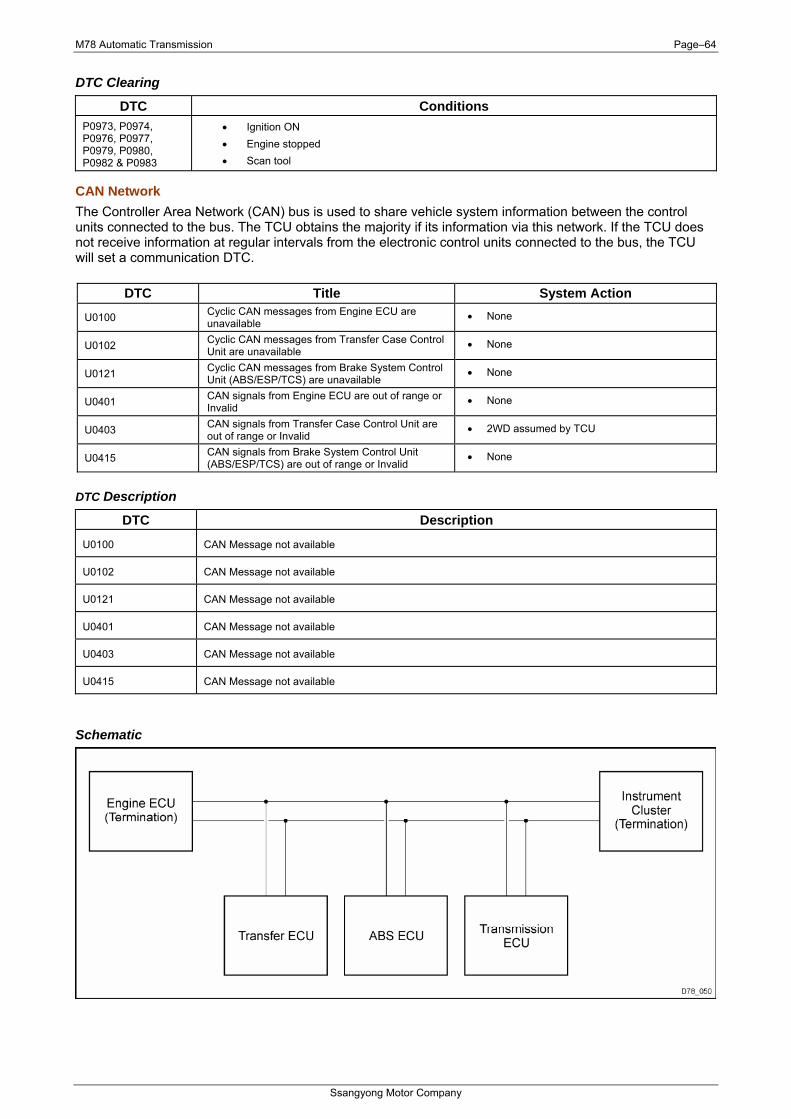
M78 Automatic Transmission Page–64
Ssangyong Motor Company
DTC Clearing
DTC Conditions P0973, P0974, P0976, P0977, P0979, P0980, P0982 & P0983
• Ignition ON • Engine stopped • Scan tool
CAN Network The Controller Area Network (CAN) bus is used to share vehicle system information between the control units connected to the bus. The TCU obtains the majority if its information via this network. If the TCU does not receive information at regular intervals from the electronic control units connected to the bus, the TCU will set a communication DTC.
DTC Title System Action
U0100 Cyclic CAN messages from Engine ECU are unavailable
• None
U0102 Cyclic CAN messages from Transfer Case Control Unit are unavailable
• None
U0121 Cyclic CAN messages from Brake System Control Unit (ABS/ESP/TCS) are unavailable
• None
U0401 CAN signals from Engine ECU are out of range or Invalid
• None
U0403 CAN signals from Transfer Case Control Unit are out of range or Invalid
• 2WD assumed by TCU
U0415 CAN signals from Brake System Control Unit (ABS/ESP/TCS) are out of range or Invalid
• None
DTC Description
DTC Description
U0100 CAN Message not available
U0102 CAN Message not available
U0121 CAN Message not available
U0401 CAN Message not available
U0403 CAN Message not available
U0415 CAN Message not available
Schematic
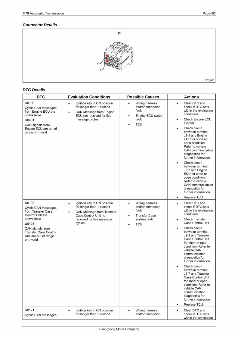
M78 Automatic Transmission Page–65
Ssangyong Motor Company
Connector Details
DTC Details
DTC Evaluation Conditions Possible Causes Actions U0100 Cyclic CAN messages from Engine ECU are unavailable U0401 CAN signals from Engine ECU are out of range or Invalid
• Ignition key in ON position for longer than 1 second
• CAN Message from Engine ECU not received for five message cycles
• Wiring harness and/or connector fault
• Engine ECU system fault
• TCU
• Clear DTC and check if DTC sets within the evaluation conditions
• Check Engine ECU system
• Check circuit between terminal J2-1 and Engine ECU for short or open condition. Refer to vehicle CAN communication diagnostics for further information
• Check circuit between terminal J2-7 and Engine ECU for short or open condition. Refer to vehicle CAN communication diagnostics for further information
• Replace TCU
U0102 Cyclic CAN messages from Transfer Case Control Unit are unavailable U0403 CAN signals from Transfer Case Control Unit are out of range or Invalid
• Ignition key in ON position for longer than 1 second
• CAN Message from Transfer Case Control Unit not received for five message cycles
• Wiring harness and/or connector fault
• Transfer Case system fault
• TCU
• Clear DTC and check if DTC sets within the evaluation conditions
• Check Transfer Case Control Unit
• Check circuit between terminal J2-1 and Transfer Case Control Unit for short or open condition. Refer to vehicle CAN communication diagnostics for further information
• Check circuit between terminal J2-7 and Transfer Case Control Unit for short or open condition. Refer to vehicle CAN communication diagnostics for further information
• Replace TCU
U0121 Cyclic CAN messages
• Ignition key in ON position for longer than 1 second
• Wiring harness and/or connector
• Clear DTC and check if DTC sets within the evaluation
M78 Automatic Transmission Page–66
Ssangyong Motor Company
DTC Evaluation Conditions Possible Causes Actions from Brake System Control Unit (ABS/ESP/TCS) are unavailable U0415 CAN signals from Brake System Control Unit (ABS/ESP/TCS) are out of range or Invalid
• CAN Message from Brake System Control Unit not received for five message cycles
fault • Brake system fault • TCU
conditions • Check Brake
System Control Unit DTC’s
• Check circuit between terminal J2-1 and Brake System Control Unit for short or open condition. Refer to vehicle CAN communication diagnostics for further information
• Check circuit between terminal J2-7 and Brake System Control Unit for short or open condition. Refer to vehicle CAN communication diagnostics for further information
• Replace TCU
DTC Clearing
DTC Conditions U0100, U0102, U0121, U0401, U0403, & U0415
• Ignition ON • Engine stopped • Scan tool
TCU Calibration TCU software or calibration may be upgraded at service. These DTC’s protect the TCU against corrupted files being loaded into the TCU. They also ensure only the correct calibration parameters are used with the software version currently loaded into the TCU.
DTC Title System Action U1601 TCU Application Software Missing or Corrupted • Transmission in LHM
U1606 TCU Calibration Error – Platform • TCU SENDS MIL REQUEST “ON”
U1607 TCU Calibration Error - Active Variant • TCU SENDS MIL REQUEST “ON”
U1608 TCU VIN Coding Error • TCU SENDS MIL REQUEST “ON”
U1609 TCU Hardware (pcb) Calibration Error • TCU SENDS MIL REQUEST “ON”
DTC Description
DTC Description
U1601 During initialisation, the TCU software was found to be missing or corrupted. In this condition the TCU will not operate, and the transmission will be in LHM
U1606 Platform calibration data CRC check failed at initialisation of TCU. This is normal for a development TCU
U1607 Active Variant calibration data CRC check failed at initialisation of TCU. This is normal for a development TCU
U1608 VIN based variant could not be determined. TCU will use default VIN calibration
U1609 Calibration for TCU hardware (pcb) is missing or corrupted. TCU will use default calibration
M78 Automatic Transmission Page–67
Ssangyong Motor Company
DTC Details DTC Evaluation Conditions Possible Causes Actions
U1601 TCU Application Software Missing or Corrupted
• Ignition key in ON position • CRC not Valid
• Corrupt application • Clear DTC and check if DTC sets within the evaluation conditions
• Update TCU calibration software. Refer to vehicle scan tool documentation for further information
• Replace TCU
U1606 TCU Calibration Error – Platform U1607 TCU Calibration Error - Active Variant
• Ignition key in ON position • CRC not valid
• TCU calibration • Clear DTC and check if DTC sets within the evaluation conditions
• Update TCU calibration software. Refer to vehicle scan tool documentation for further information
• Replace TCU
U1608 TCU VIN Coding Error
• Ignition key in ON position • VIN not compatible with
calibration
• TCU calibration • TCU replaced but
VIN code not set.
• Clear DTC and check if DTC sets within the evaluation conditions
• Update TCU calibration software. Refer to vehicle scan tool documentation for further information
U1609 TCU Hardware (pcb) Calibration Error
• Ignition key in ON position • TCU manufacturing
information not present
• TCU • Clear DTC and check if DTC sets within the evaluation conditions
• Replace TCU
DTC Clearing
DTC Conditions U1601, U1606, U1607, U1608 & U1609
• Ignition ON • Engine stopped • Scan tool
M78 Automatic Transmission Page–68
Ssangyong Motor Company
3 Maintenance Operations
3.1 Stall Test Stall testing can be performed on the Model 78 6 speed automatic transmission to determine whether the transmission clutches can hold the full engine torque without slipping. Stall testing should be performed for a period no longer then 10 seconds. • Apply Hand Brake • Start Engine • Press Brake Pedal • Shift to “DRIVE” • Press Accelerator Pedal to 100 % for 6 seconds • Observe Engine speed • Release Accelerator Pedal • Shift To Reverse • Press Accelerator Pedal to 100 % for 6 seconds • Observe Engine speed If engine speed is observed > 3000 rpm; transmission hardware failure
3.2 Transmission Reset Procedure (Replacement Transmission) It is necessary to reset the adaptive data stored within the transmission control unit (TCU) when the transmission and or TCU have been replaced.
Green Offset Reset Carried out when a replacement transmission has been installed in a vehicle.
Adaptive Reset Carried out when one of the following has occurred:
• Replace transmission • Replace TCU
Green Offset Reset Procedure To perform a green offset reset procedure, proceed as follows:
1. Connect the vehicle’s diagnostic scan tool to the vehicles diagnostic connector. Refer to the vehicle repair manual for information on connecting the scan tool.
2. With the transmission gear select (TGS) lever in Park, turn the ignition key to the ON position (engine not running).
3. Using the scan tool, set the parameter Set Km Travelled to 0Km. 4. Run the task Activate Adaptive Green Offset. 5. Turn the ignition key to the OFF position. 6. Start the vehicle and check for normal operation.
Adaptive Reset Procedure To perform an adaptive reset procedure, proceed as follows:
1. Connect the vehicle’s diagnostic scan tool to the vehicles diagnostic connector. Refer to the vehicle repair manual for information on connecting the scan tool.
2. With the transmission gear select (TGS) lever in Park, turn the ignition key to the ON position (engine not running).
3. Set the parameter Set Km Travelled to 0 Km. 4. Run the task Reset Adaptive Data. 5. Turn the ignition key to the OFF position. 6. Start the vehicle and check for normal operation.
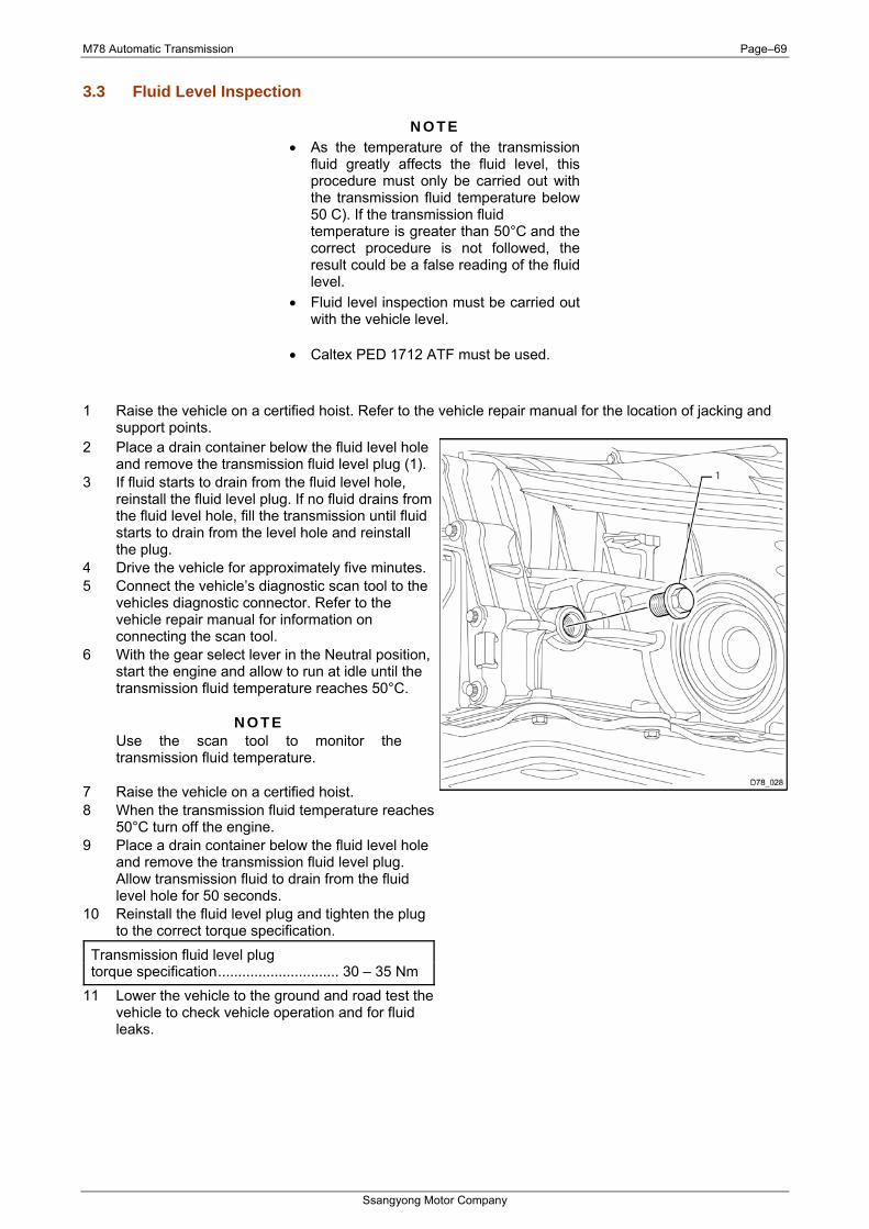
M78 Automatic Transmission Page–69
Ssangyong Motor Company
3.3 Fluid Level Inspection
N O T E • As the temperature of the transmission
fluid greatly affects the fluid level, this procedure must only be carried out with the transmission fluid temperature below 50 C). If the transmission fluid temperature is greater than 50°C and the correct procedure is not followed, the result could be a false reading of the fluid level.
• Fluid level inspection must be carried out with the vehicle level.
• Caltex PED 1712 ATF must be used. 1 Raise the vehicle on a certified hoist. Refer to the vehicle repair manual for the location of jacking and
support points. 2 Place a drain container below the fluid level hole
and remove the transmission fluid level plug (1).3 If fluid starts to drain from the fluid level hole,
reinstall the fluid level plug. If no fluid drains from the fluid level hole, fill the transmission until fluid starts to drain from the level hole and reinstall the plug.
4 Drive the vehicle for approximately five minutes.5 Connect the vehicle’s diagnostic scan tool to the
vehicles diagnostic connector. Refer to the vehicle repair manual for information on connecting the scan tool.
6 With the gear select lever in the Neutral position, start the engine and allow to run at idle until the transmission fluid temperature reaches 50°C.
N O T E Use the scan tool to monitor the transmission fluid temperature.
7 Raise the vehicle on a certified hoist. 8 When the transmission fluid temperature reaches
50°C turn off the engine. 9 Place a drain container below the fluid level hole
and remove the transmission fluid level plug. Allow transmission fluid to drain from the fluid level hole for 50 seconds.
10 Reinstall the fluid level plug and tighten the plug to the correct torque specification.
Transmission fluid level plug torque specification.............................. 30 – 35 Nm
11 Lower the vehicle to the ground and road test the vehicle to check vehicle operation and for fluid leaks.
M78 Automatic Transmission Page–70
Ssangyong Motor Company
3.4 Transmission Cooler and Hydraulic Line Flushing Procedure (New Transmission)
N O T E To prevent transmission damage due to contaminants being present in the transmission cooler and/or hydraulic lines, the cooler and lines must be flushed.
1 Raise the vehicle on a certified hoist. Refer to the vehicle repair manual for the location of jacking and support points.
2 Using compressed air, clear the cooler lines of any residual fluid. 3 Connect the front transmission cooler line to the transmission.
Front transmission cooler line to transmission fitting torque specification.............................. 25 – 35 Nm
4 Connect one end of a rubber hose to the end of the rear cooler line and place the other end in a suitable container to collect the transmission fluid as it is pumped out.
5 Start the engine and run for approximately 30 seconds at idle. (With ATF at 50°C temperature, a minimum of 2.5litres oil flow after 30 seconds.)
6 Whist the engine is running, have an assistant pump transmission fluid into the transmission fluid level hole.
7 Connect the rear transmission cooler line to the transmission. Rear transmission cooler line to transmission fitting torque specification.............................. 25 – 35 Nm
8 Check the transmission fluid level; refer to Fluid Level Inspection on page 69.
M78 Automatic Transmission Page–71
Ssangyong Motor Company
4 Lubrication Automatic transmission fluid ................................................... Caltex PED 1712 ATF
M78 Automatic Transmission Page–72
Ssangyong Motor Company
5 Torque Specifications Transmission fluid level plug.................................................................... 30 – 35 Nm Front transmission cooler line to transmission connector........................ 25 – 35 Nm Rear transmission cooler line to transmission cooler connector.............. 25 – 35 Nm Torque converter to drive plate bolt ......................................................... 40 – 42 Nm Transmission selector lever to cross shaft nut......................................... 14 – 20 Nm
Appendix I
Ssangyong Motor Company
CDPFL/Differential

CDPF(Catalyst & Diesel Particulate Filter)
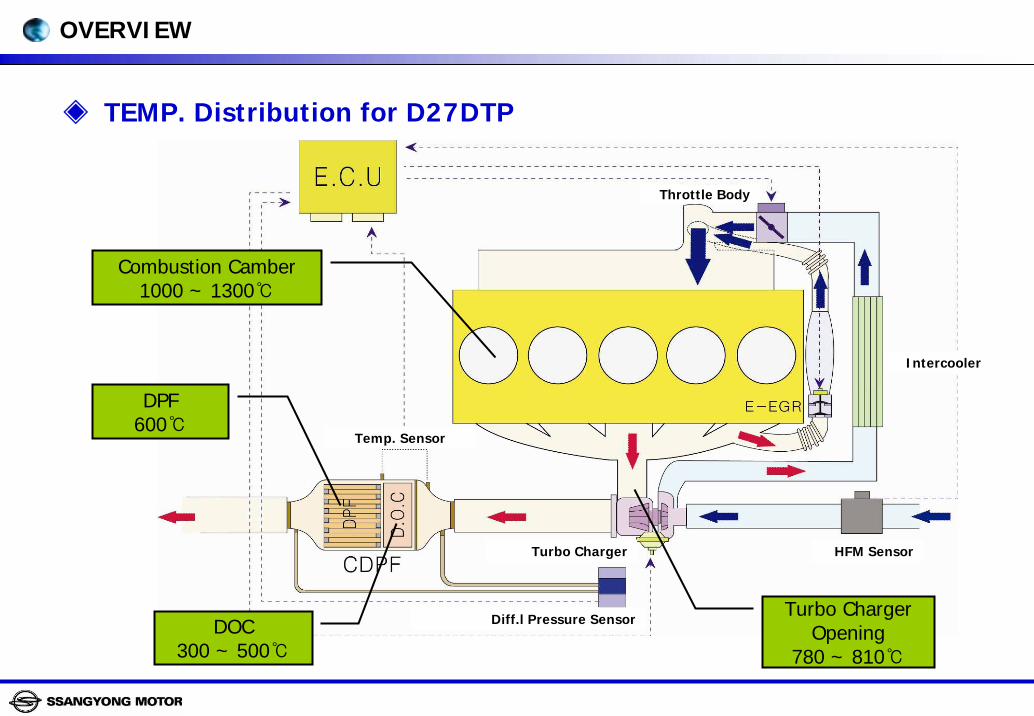
OVERVIEW
TEMP. Distribution for D27DTP
Combustion Camber1000 ~ 1300
Turbo Charger Opening
780 ~ 810
DOC300 ~ 500
DPF600
Temp. Sensor
Turbo Charger
Diff.l Pressure Sensor
HFM Sensor
Intercooler
Throttle Body
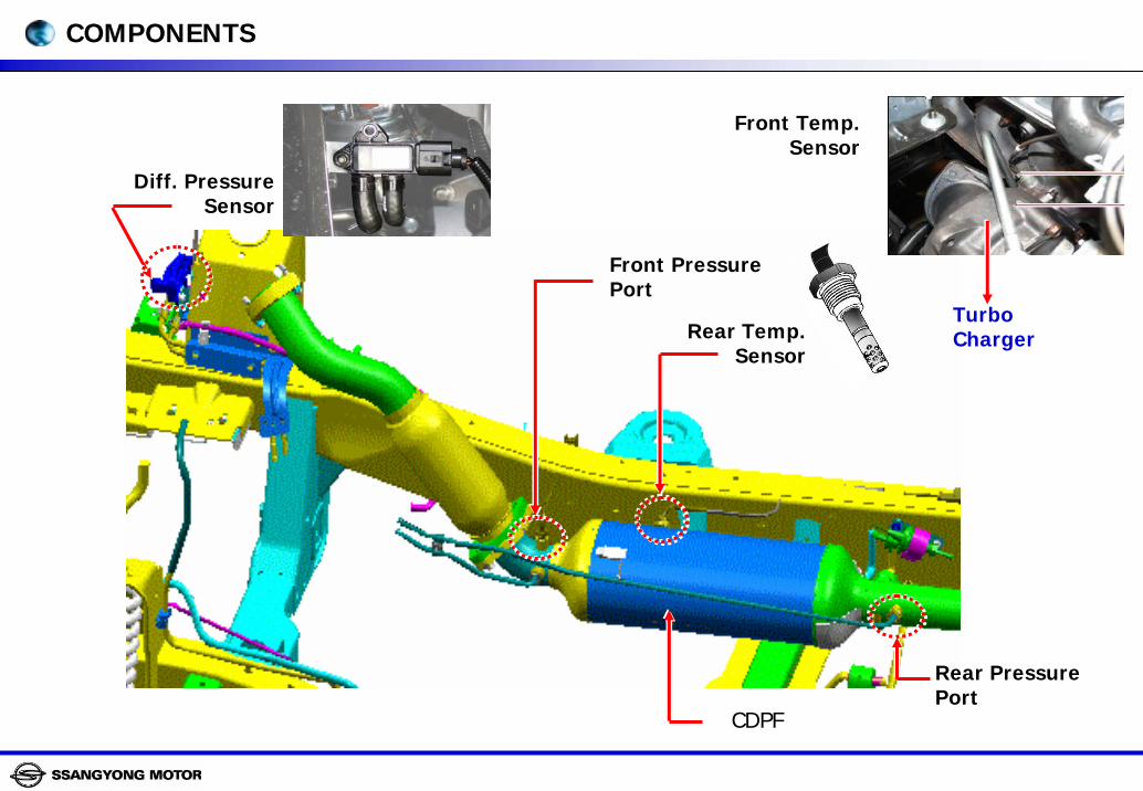
Diff. Pressure Sensor
Front Pressure Port
Rear Temp. Sensor
CDPF
Rear Pressure Port
Front Temp. Sensor
Turbo Charger
COMPONENTS
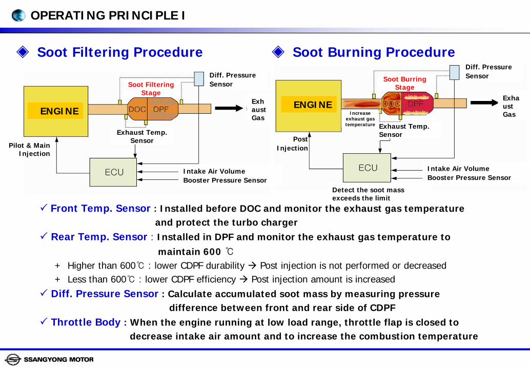
Front Temp. Sensor : Installed before DOC and monitor the exhaust gas temperature and protect the turbo charger
Rear Temp. Sensor : Installed in DPF and monitor the exhaust gas temperature tomaintain 600
+ Higher than 600 : lower CDPF durability Post injection is not performed or decreased+ Less than 600 : lower CDPF efficiency Post injection amount is increased
Diff. Pressure Sensor : Calculate accumulated soot mass by measuring pressure difference between front and rear side of CDPF
Throttle Body : When the engine running at low load range, throttle flap is closed todecrease intake air amount and to increase the combustion temperature
Soot Filtering Procedure Soot Burning Procedure
ENGINE
Intake Air VolumeBooster Pressure Sensor
Diff. PressureSensor
Exhaust Temp. Sensor
Soot Burring Stage
Exhaust Gas
Detect the soot mass exceeds the limit
Increase exhaust gas temperature
Post Injection
ENGINE
Exhaust Temp. Sensor
Intake Air VolumeBooster Pressure Sensor
Soot Filtering Stage
Diff. PressureSensor
Exhaust Gas
Pilot & Main Injection
OPERATING PRINCIPLE I
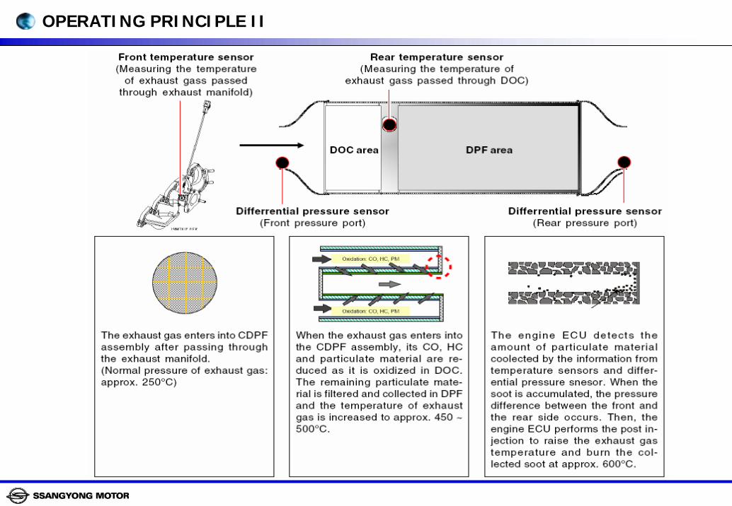
OPERATING PRINCIPLE II
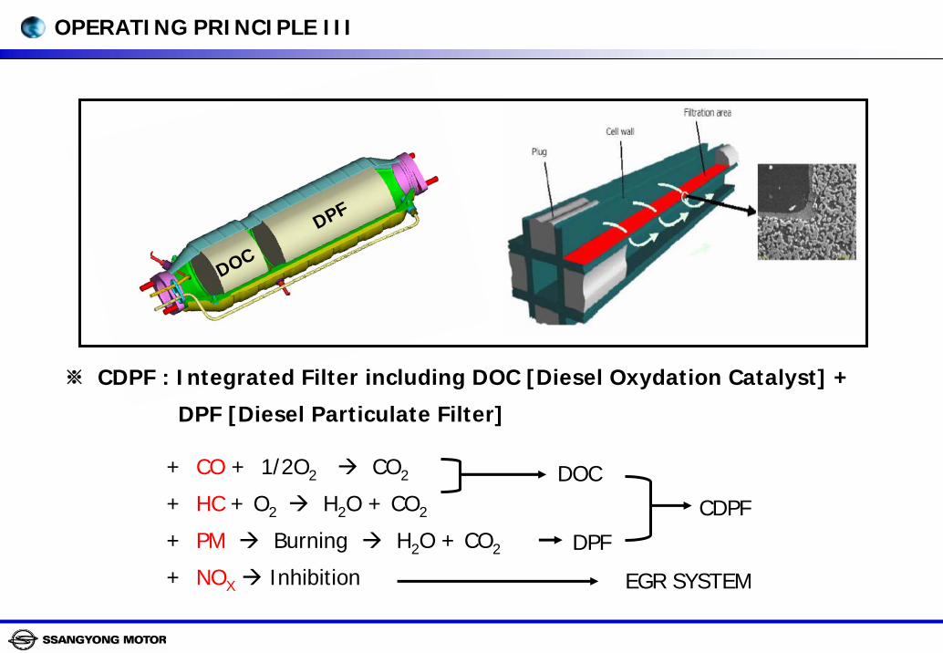
※ CDPF : Integrated Filter including DOC [Diesel Oxydation Catalyst] +
DPF [Diesel Particulate Filter]
+ CO + 1/2O2 CO2
+ HC + O2 H2O + CO2
+ PM Burning H2O + CO2
+ NOX Inhibition
DOC
DPF
EGR SYSTEM
CDPF
DOC
DPF
OPERATING PRINCIPLE III
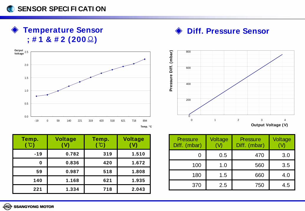
0.0
0.5
1.0
1.5
2.0
2.5
-19 0 59 140 221 319 420 518 621 718 894
Temp. °C
OutputVoltage
Temperature Sensor; #1 & #2 (200Ω)
Temp.()
Voltage(V)
Temp.()
0.782 319
420
518
140 1.168 621 1.935
718
0.836
0.987
1.334
Voltage(V)
-19 1.510
0 1.672
59 1.808
221 2.043
0
200
400
600
800
0 1 2 3 4
Output Voltage (V)
Pre
ssu
re D
iff.
(m
bar)
PressureDiff. (mbar)
Voltage(V)
PressureDiff. (mbar)
0.5 470
560
660
370 2.5 750 4.5
1.0
1.5
Voltage(V)
0 3.0
100 3.5
180 4.0
Diff. Pressure Sensor
SENSOR SPECIFICATION
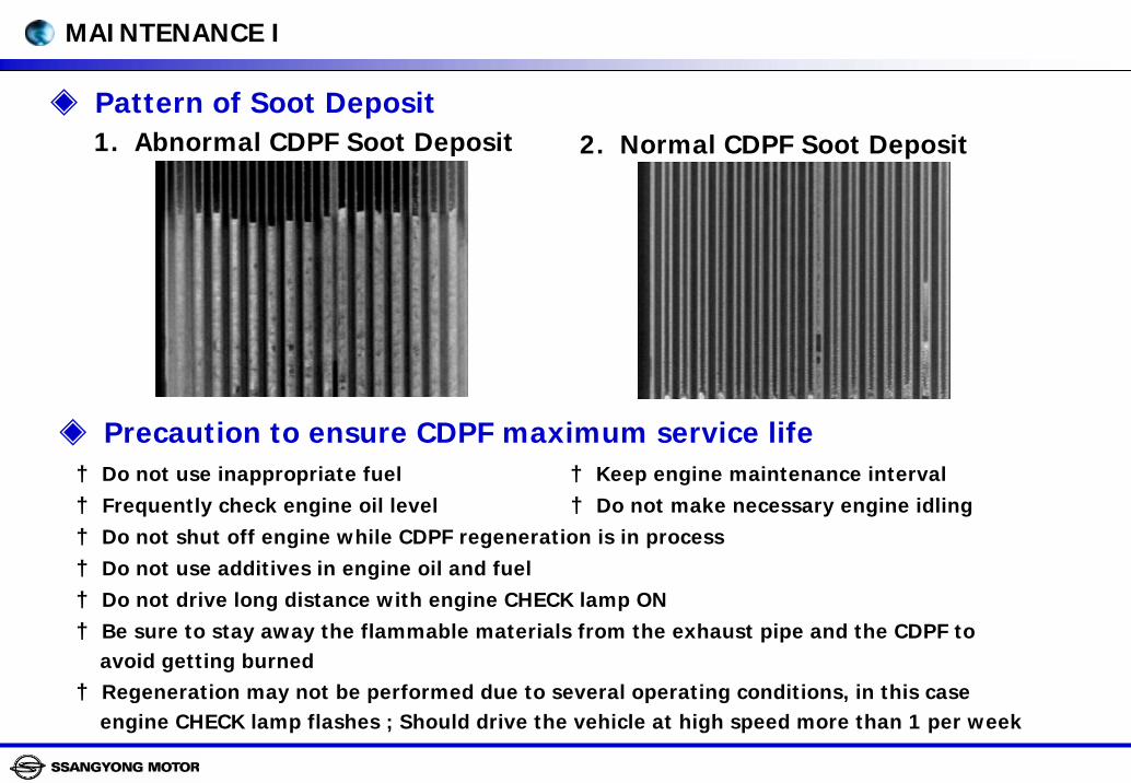
Pattern of Soot Deposit1. Abnormal CDPF Soot Deposit 2. Normal CDPF Soot Deposit
Precaution to ensure CDPF maximum service life† Do not use inappropriate fuel † Keep engine maintenance interval† Frequently check engine oil level † Do not make necessary engine idling† Do not shut off engine while CDPF regeneration is in process† Do not use additives in engine oil and fuel † Do not drive long distance with engine CHECK lamp ON† Be sure to stay away the flammable materials from the exhaust pipe and the CDPF to
avoid getting burned† Regeneration may not be performed due to several operating conditions, in this case
engine CHECK lamp flashes ; Should drive the vehicle at high speed more than 1 per week
MAINTENANCE I
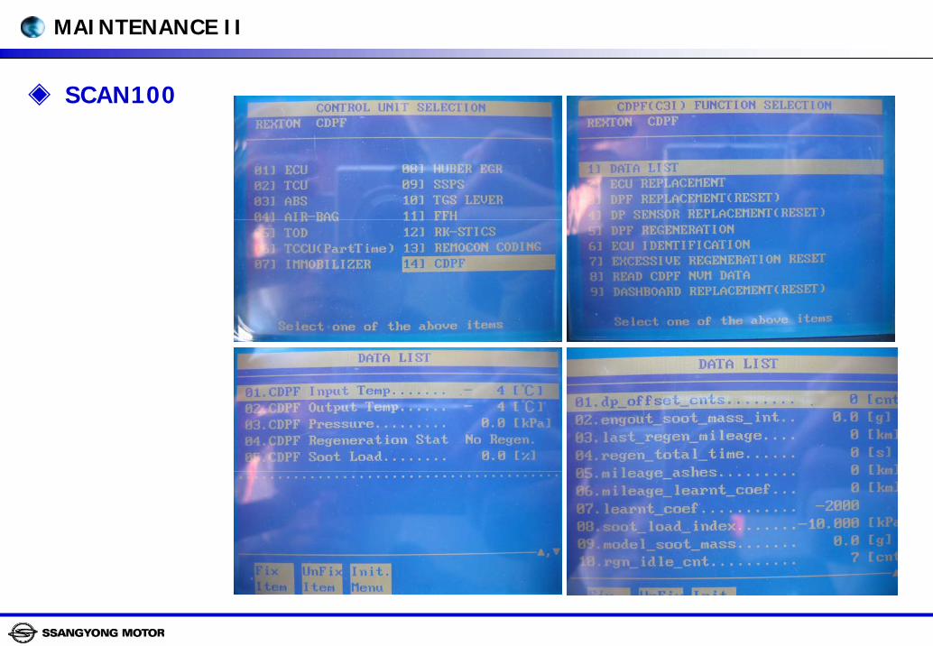
SCAN100
MAINTENANCE II
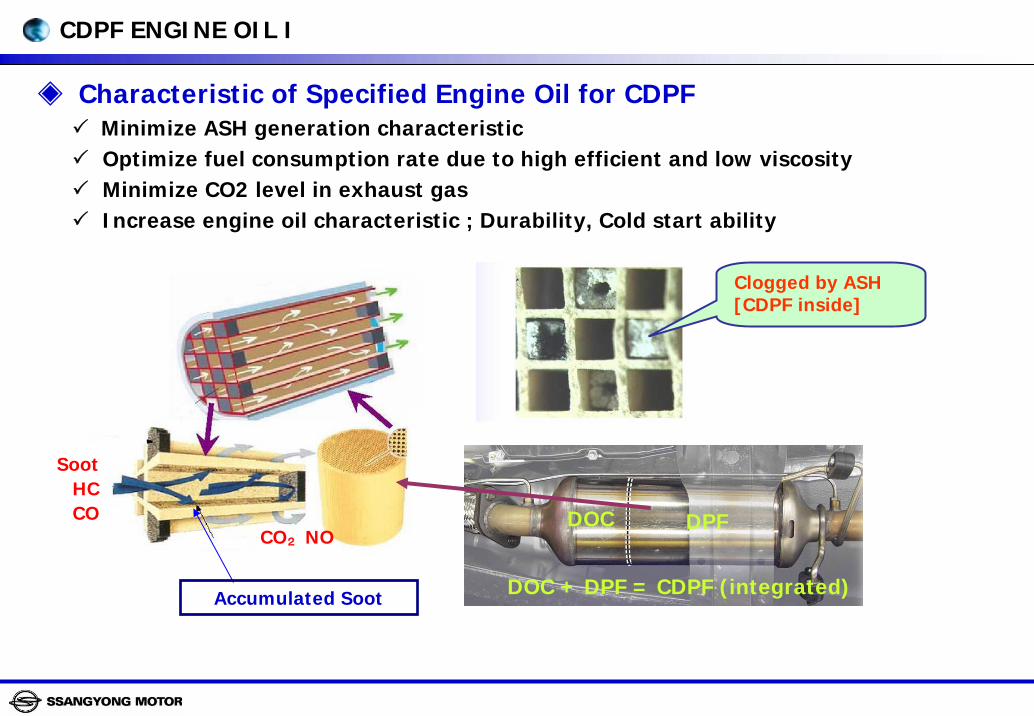
Characteristic of Specified Engine Oil for CDPFMinimize ASH generation characteristic Optimize fuel consumption rate due to high efficient and low viscosityMinimize CO2 level in exhaust gasIncrease engine oil characteristic ; Durability, Cold start ability
Clogged by ASH[CDPF inside]
Accumulated Soot
SootHCCO
CO₂NODOC DPF
DOC + DPF = CDPF (integrated)
CDPF ENGINE OIL I
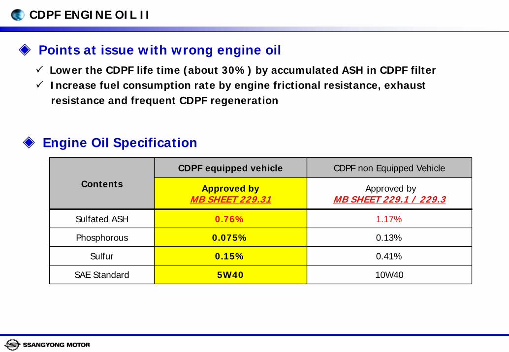
Points at issue with wrong engine oilLower the CDPF life time (about 30%) by accumulated ASH in CDPF filter Increase fuel consumption rate by engine frictional resistance, exhaustresistance and frequent CDPF regeneration
Engine Oil Specification
CDPF equipped vehicle CDPF non Equipped Vehicle
Approved byMB SHEET 229.31
Approved byMB SHEET 229.1 / 229.3
Sulfated ASH 0.76% 1.17%
Phosphorous 0.075% 0.13%
Sulfur 0.15% 0.41%
SAE Standard 5W40 10W40
Contents
CDPF ENGINE OIL II

LD(Locking Differential)

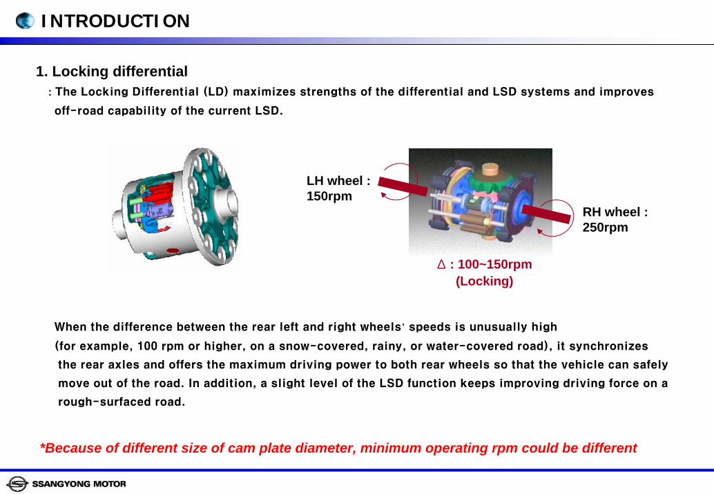
1. Locking differential: The Locking Differential (LD) maximizes strengths of the differential and LSD systems and improves
off-road capability of the current LSD.
When the difference between the rear left and right wheels’ speeds is unusually high
(for example, 100 rpm or higher, on a snow-covered, rainy, or water-covered road), it synchronizes
the rear axles and offers the maximum driving power to both rear wheels so that the vehicle can safely
move out of the road. In addition, a slight level of the LSD function keeps improving driving force on a
rough-surfaced road.
*Because of different size of cam plate diameter, minimum operating rpm could be different
INTRODUCTION
RH wheel : 250rpm
LH wheel : 150rpm
Δ : 100~150rpm (Locking)
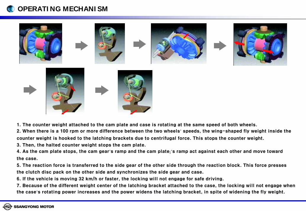
1. The counter weight attached to the cam plate and case is rotating at the same speed of both wheels.
2. When there is a 100 rpm or more difference between the two wheels’ speeds, the wing-shaped fly weight inside the
counter weight is hooked to the latching brackets due to centrifugal force. This stops the counter weight.
3. Then, the halted counter weight stops the cam plate.
4. As the cam plate stops, the cam gear’s ramp and the cam plate¡’s ramp act against each other and move toward
the case.
5. The reaction force is transferred to the side gear of the other side through the reaction block. This force presses
the clutch disc pack on the other side and synchronizes the side gear and case.
6. If the vehicle is moving 32 km/h or faster, the locking will not engage for safe driving.
7. Because of the different weight center of the latching bracket attached to the case, the locking will not engage when
the case’s rotating power increases and the power widens the latching bracket, in spite of widening the fly weight.
① ② ③
④⑤
OPERATING MECHANISM
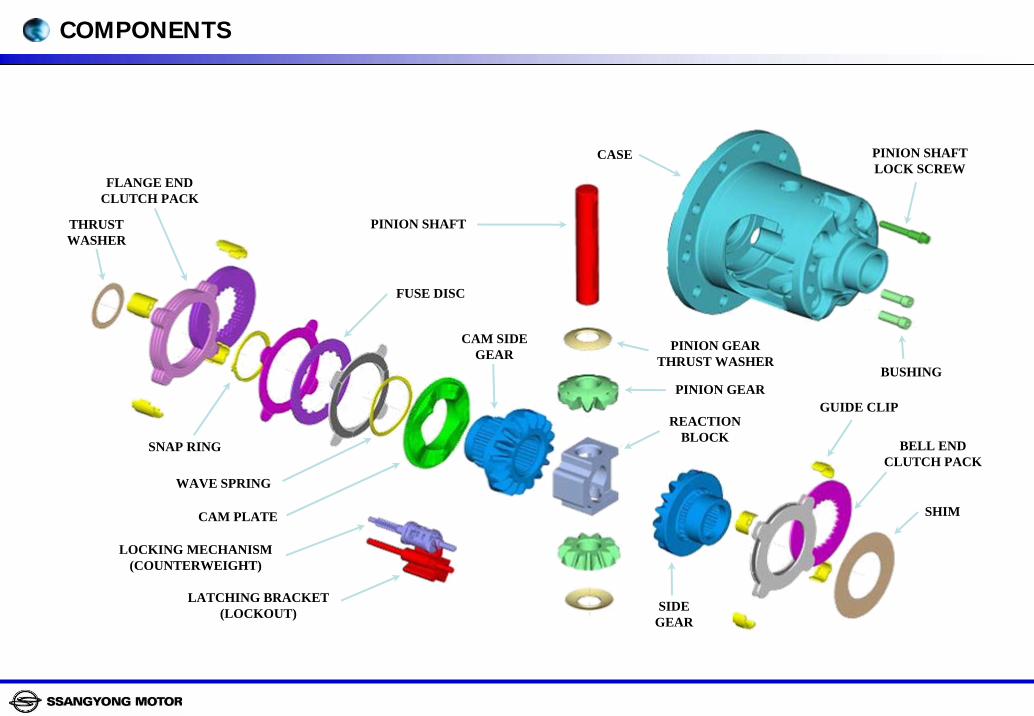
SHIM
GUIDE CLIP
CASE PINION SHAFTLOCK SCREW
BUSHING
PINION SHAFT
PINION GEARTHRUST WASHER
PINION GEAR
REACTIONBLOCK
SIDEGEAR
BELL ENDCLUTCH PACK
CAM SIDEGEAR
LATCHING BRACKET(LOCKOUT)
LOCKING MECHANISM(COUNTERWEIGHT)
CAM PLATE
WAVE SPRING
FUSE DISC
THRUSTWASHER
SNAP RING
FLANGE ENDCLUTCH PACK
COMPONENTS

![-EnmEEEEEEEEEm · 2014. 9. 27. · Ju1]M78/ Prepared for Agency for Defense Development "I Republic of Korea Prepared by BLOCK ENGINEERING, INC. ... Transmission cable length 2000](https://img.pdfslide.us/doc/110x75/6124acedab6f8b434977f58a/enmeeeeeeeeem-2014-9-27-ju1m78-prepared-for-agency-for-defense-development.jpg)


![Functional Encryption for Regular Languages · PDF fileFunctional Encryption for Regular Languages Brent Waters . 2 Public Key Encryption [DH76,M78,RSA78,GM84] Avoid Prior Secret Exchange](https://img.pdfslide.us/doc/110x75/5aa494807f8b9ac8748c2249/functional-encryption-for-regular-languages-encryption-for-regular-languages-brent.jpg)