Embed Size (px)
Citation preview
Venkatesh . N.Int. Journal of Engineering Research and Applications www.ijera.com
ISSN : 2248-9622, Vol. 5, Issue 5, ( Part -6) May 2015, pp.89-95
www.ijera.com 89 | P a g e
Numerical Investigation Of Compression Performance Of
Different Blade Configuration In Co-Rotor Turbo-Propeller
Venkatesh . N *, Balaji .S ** *(Department of Aeronautical Engineering, Anna University, Chennai.)
** (Department of Aeronautical Engineering, Anna University, Chennai)
ABSTRACT This project work is to investigate the compression efficiency of different configuration of Turbo-Prop Co-
Rotor Blade System of Subsonic Axial Flow Compressor. By this method the highly compressed air can be
passed over the intake of the engine to the compressor with high mass flow rate in change of low velocity and
high pressure ratio. The length of the small rotor is varied in terms of large rotor length by 25,50 & 75% . Each
will have three space configuration in terms of diameter of rotor and in the percentage of 5,10,15%. A total of
12 configurations will be simulated to arrive optimum blade configuration. The blades are made in the shape of
an airfoil like wing of an aircraft. The engine rotates the propeller blades, which produce lift. This lift is called
thrust and moves the aircraft forward. Blades are usually made of high lift airfoil which allows more rotation to
generate high pressure for engine. ANSYS- Fluent is commercial software which is robust for most of the fluid
dynamic problems and it is used in this project work to evaluate the different configurations of co-rotor
propeller system to arrive the best.
Keywords- compression efficiency, high mass flow rate, high pressure ratio, ANSYS - Fluent.
I. INTRODUCTION Aircraft propellers or airscrews convert rotary
motion from piston engines, turboprops or electric
motors to provide propulsive force. They may be
fixed or variable pitch. Early aircraft propellers were
carved by hand from solid or laminated wood with
later propellers being constructed from metal. The
most modern propeller designs use high-technology
composite materials. The propeller is usually
attached to the crankshaft of a piston engine, either
directly or through a reduction unit. Light aircraft
engines often do not require the complexity of
gearing but on larger engines and turboprop aircraft
it is essential. Propellers are made of airfoil with
high life and low drag. The blades are made in the
shape of an airfoil like wing of an aircraft.
When the engine rotates the propeller blades, the
blades produce lift. This lift is called thrust and
moves the aircraft forward. Most aircraft have
propellers that pull the aircraft through the air.
Blades are usually made of high lift airfoil which
allows more rotation to generate high pressure for
engine.
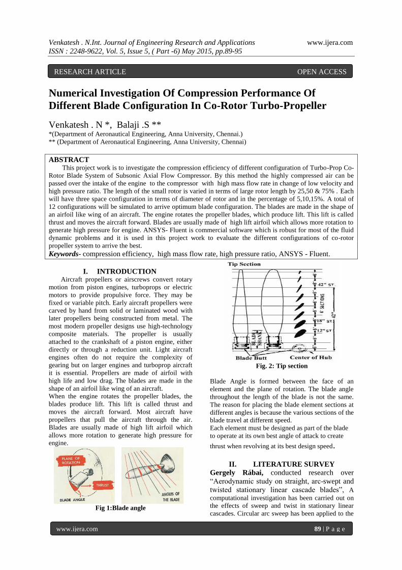
Fig 1:Blade angle
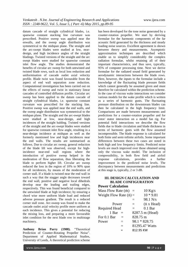
Fig. 2: Tip section
Blade Angle is formed between the face of an
element and the plane of rotation. The blade angle
throughout the length of the blade is not the same.
The reason for placing the blade element sections at
different angles is because the various sections of the
blade travel at different speed.
Each element must be designed as part of the blade
to operate at its own best angle of attack to create
thrust when revolving at its best design speed.
II. LITERATURE SURVEY Gergely Rábai, conducted research over
“Aerodynamic study on straight, arc-swept and
twisted stationary linear cascade blades”, A
computational investigation has been carried out on
the effects of sweep and twist in stationary linear
cascades. Circular arc sweep has been applied to the
RESEARCH ARTICLE OPEN ACCESS
Venkatesh . N.Int. Journal of Engineering Research and Applications www.ijera.com
ISSN : 2248-9622, Vol. 5, Issue 5, ( Part -6) May 2015, pp.89-95
www.ijera.com 90 | P a g e
datum cascade of straight cylindrical blades, i.e.
spanwise constant stacking line curvature was
prescribed. Positive sweep was applied near the
enwalls, and the sweep angle distribution was
symmetrical to the midspan plane. The straight and
the arc-swept blades were studied at low, near-
design, and high incidence angles of the straight
bladings. Twisted versions of the straight and the arc
swept blades were studied for spanwise constant
inlet flow angle. The studies demonstrated the
benefits of circular arc sweep for both untwisted and
twisted blade rows, such as local loss reduction and
uniformisation of cascade outlet axial velocity
profile. Blade twist was found favourable from the
aspect of end wall separation zone reduction.
Computational investigation has been carried out on
the effects of sweep and twist in stationary linear
cascades of controlled diffusion profile. Circular arc
sweep has been applied to the datum cascade of
straight cylindrical blades, i.e. spanwise constant
curvature was prescribed for the stacking line.
Positive sweep was applied near the end walls, and
the sweep angle distribution was symmetrical to the
midspan plane. The straight and the arc-swept blades
were studied at low, near-design, and high
incidences of the straight balding. Twisted versions
of the straight and the arc-swept blades were studied
for spanwise constant inlet flow angle, resulting in a
near-design incidence at midspan as well as the
formerly mentioned low and high incidences near
the end walls. The results are summarised as
follows. Due to circular arc sweep, general reduction
of the blade lift was observed, except for high-
incidence near-end wall regions where the
introduction of positive sweep helped in the
moderation of flow separation, thus liberating the
blade to perform higher lift. Circular arc sweep
reduced the loss in the region of 10% to 90% span
for all incidences, by means of the moderation of
corner stall. If a blade is twisted near the end wall in
such a way that the stagger angle decreases toward
the end wall, positive and negative local dihedrals
develop near the leading and trailing edges,
respectively. This was found beneficial compared to
the untwisted blade at high incidence; by ensuring a
chord wise more uniform blade load and reduced
adverse pressure gradient. The result is a reduced
corner stall zone. Arc-sweep was found to make the
cascade outlet axial velocity profile more uniform at
each incidence. This gives a potential for reducing
the mixing loss, and preparing a more favourable
inlet condition for the next blade row in multistage
machinery.
Anthony Brian Parry (1988). “Theoretical
Prediction of Counter-Rotating Propeller Noise”.
Department of Applied Mathematical Studies,
University of Leeds, A theoretical prediction scheme
has been developed for the tone noise generated by a
counter-rotation propeller. We start by deriving
formulae for the harmonic components of the far
acoustic field generated by the thickness and steady
loading noise sources. Excellent agreement is shown
between theory and measurements. Asymptotic
approximation techniques are described which
enable us to simplify considerably the complex
radiation formulae, whilst retaining all of their
important characteristics, and thus save, typically,
95% of computer processing time. Next we derive
formulae for the radiated sound field generated by
aerodynamic interactions between the blade rows.
Here, however, the inputs to the formulae include a
knowledge of the fluctuating blade pressure fields
which cannot generally be assumed given and must
therefore be calculated within the prediction scheme.
In the case of viscous wake interactions we consider
various models for the wake profile which is written
as a series of harmonic gusts. The fluctuating
pressure distribution on the downstream blades can
then be calculated in the high frequency limit.
Comparisons are made between measurements and
predictions for a counter-rotation propeller and for
rotor/ stator interaction on a model fan rig. For
potential field interactions we describe the flow
fields due to blade circulation and blade thickness in
terms of harmonic gusts with the flow assumed
incompressible. The blade response is calculated for
both finite and semi-infinite airfoils. Some important
differences between these two cases are noted in
both high and low frequency limits. Predicted noise
levels are much improved over those obtained using
only the viscous wake model. The inclusion of
compressibility, in both flow field and airfoil
response calculations, provides a further
improvement in the predicted noise levels. The
discrepancy between measurements and predictions
at this stage is, typically, 2 or 3 dB.
III. DESIGN CALCULATION AND
BLADE CONFIGURATION
Power Calculation
Mass Flow Rate (ṁ) = 10 Kg/s
Weight Flow Rate (ṅ) = 10 * 9.81
= 98.1 N/s
Power = (ṅ x Head)
Required Head = 0.1 Bar
1 Bar = 8287.5 m (Head)
For 0.1 Bar = 828.75 m
Power = 98.1 * 828.75
= 81295.47 Watts = 812.95 KW

Venkatesh . N.Int. Journal of Engineering Research and Applications www.ijera.com
ISSN : 2248-9622, Vol. 5, Issue 5, ( Part -6) May 2015, pp.89-95
www.ijera.com 91 | P a g e
Fig.3: Blade Configuration
Model Parameters Rotor diameter = 200 mm Hub Diameter = 67 mm Blade Height = 67 mm
Airfoil = NACA 65A010 Angle of Attack= 10°
IV. PROPELLER DESIGN
Fig. 4: Straight Sweep Co-Rotor Configuration
40%, 60% & 80% Ratio
Fig. 5: Arc Sweep Co-Rotor Configuration 40%,
60% & 80% Ratio
Fig. 6: Twisted Swept Co-Rotor Configuration
40%, 60% & 80% Ratio
Fig. 7: Twisted Arc Swept Co-Rotor Configuration
40%, 60% & 80% Ratio
Fig. 8: Diameter Vs RPM
V. SIMULATION RESULTS AND
DISCUSSION
SSB 40% Configuration
F
ig. 9 : Pressure & Total Pressure
Fi
g. 10 - Temperature & Density
SSB 60% Configuration

Venkatesh . N.Int. Journal of Engineering Research and Applications www.ijera.com
ISSN : 2248-9622, Vol. 5, Issue 5, ( Part -6) May 2015, pp.89-95
www.ijera.com 92 | P a g e
Fig. 11 : Pressure & Total Pressure
Fig. 12: Temperature & Density
SSB 80% Configuration
Fig. 13 : Pressure & Total Pressure
Fig. 14 - Temperature & Density
ASB 40% Configuration
Fig. 15 : Pressure & Total Pressure
Fig. 16: Temperature & Density
ASB 60% Configuration
Fig. 17 : Pressure & Total Pressure
Fig. 18: Temperature & Density
ASB 80% Configuration

Venkatesh . N.Int. Journal of Engineering Research and Applications www.ijera.com
ISSN : 2248-9622, Vol. 5, Issue 5, ( Part -6) May 2015, pp.89-95
www.ijera.com 93 | P a g e
Fig. 19 : Pressure & Total Pressure
Fig. 20: Temperature & Density
TSB 40% Configuration
Fig. 21 : Pressure & Total Pressure
Fig. 22: Temperature & Density
TSB 60% Configuration
Fig. 23 : Pressure & Total Pressure
Fig. 24: Temperature & Density
TSB 80% Configuration
Fig. 25 : Pressure & Total Pressure
Fig. 26: Temperature & Density
ATSB 40% Configuration

Venkatesh . N.Int. Journal of Engineering Research and Applications www.ijera.com
ISSN : 2248-9622, Vol. 5, Issue 5, ( Part -6) May 2015, pp.89-95
www.ijera.com 94 | P a g e
Fig. 27 : Pressure & Total Pressure
Fig. 28: Temperature & Density
ATSB 60% Configuration
Fig. 29 : Pressure & Total Pressure
Fig. 30: Temperature & Density
ATSB 80% Configuration
Fig. 31 : Pressure & Total Pressure
Fig. 32: Temperature & Density
The 12 different configuration of the co-rotor
propeller is designed and analysed using CFD
simulation. For a single design with different blade
configuration the improvement is good and the
single blade model showed a variation from 10 to 40
Kg/s from a designed 10 Kg/s and the co-rotor
models showed mixed-response and the Arc Twisted
Swept Blade with 80% co-rotor model is crowned
the best model of all configuration.
Model Single Co-Rotor
40% 60% 80%
SSB 23.320 44.040 23.000 27.830
ASB 30.140 27.830 3.400 5.781
TSB 10.000 4.401 4.610 4.720
ATSB 41.370 13.800 31.800 42.575
Fig.33 Results Details
Fig.34 Chart Results

Venkatesh . N.Int. Journal of Engineering Research and Applications www.ijera.com
ISSN : 2248-9622, Vol. 5, Issue 5, ( Part -6) May 2015, pp.89-95
www.ijera.com 95 | P a g e
VI. CONCLUSION The initial phase covered objective formulation
followed by detailed literature review which
provided details of propeller design, method,
development over years, standard documents for
propeller design and modelling, different types and
their advantages and limitations from this research
gap is found out and a solution is proposed and a
methodology is formulated for research work and
the same is followed to successfully complete this
work.
In the final phase 12 different configuration of the
propeller model is designed and modelled and
analysed for its improvement from the design point
and from the result discussion it is found that the arc
twisted swept blade with 80% radius configuration
has got the maximum advantage and is better of the
all.
As a further proceeding the final design can be
manufactured and tested in the wind tunnel to a
access more precious characters of the propeller
blade and implement in turbo prop-engines.
REFERENCE [1] Gergely Rábai, et.al.(2009). “Aerodynamic
study on straight, arc-swept and twisted
stationary linear cascade blades”, Rperiodica
polytechnica, Mechanical Engineering, 53/1
(2009) 33–40,doi: 10.3311/pp.me.2009-1.05.
[2] Anthony Brian Parry (1988). “Theoretical
Prediction of Counter-Rotating Propeller
Noise”. Department of Applied Mathematical
Studies, University of Leeds.


