Embed Size (px)
Citation preview

M4RTU/M4 I/OUSER’S GUIDE
Form 676-020322 — March, 2002
43044 Business Park Drive, Temecula, CA 92590-3614Phone: 800-321-OPTO (6786) or 951-695-3000
Fax: 800-832-OPTO (6786) or 951-695-2712www.opto22.com
Product Support Services:800-TEK-OPTO (835-6786) or 951-695-3080
Fax: 951-695-3017E-mail: [email protected]
Web: support.opto22.com

2 M4RTU/M4 I/O User’s Guide
M4RTU/M4 I/O User’s GuideForm 676-020322— March, 2002
All rights reserved.Printed in the United States of America.
The information in this manual has been checked carefully and is believed to be accurate; however, Opto 22assumes no responsibility for possible inaccuracies or omissions. Specifications are subject to change withoutnotice.
Opto 22 warrants all of its products to be free from defects in material or workmanship for 30 months from themanufacturing date code. This warranty is limited to the original cost of the unit only and does not coverinstallation, labor, or any other contingent costs. Opto 22 I/O modules and solid-state relays with date codes of1/96 or later are guaranteed for life. This lifetime warranty excludes reed relay, SNAP serial communicationmodules, SNAP PID modules, and modules that contain mechanical contacts or switches. Opto 22 does notwarrant any product, components, or parts not manufactured by Opto 22; for these items, the warranty from theoriginal manufacturer applies. These products include, but are not limited to, the OptoTerminal-G70,OptoTerminal-G75, and Sony Ericsson GT-48; see the product data sheet for specific warranty information. Referto Opto 22 form number 1042 for complete warranty information.
Opto 22 FactoryFloor, Cyrano, Optomux, and Pamux are registered trademarks of Opto 22. Generation 4,ioControl, ioDisplay, ioManager, ioProject, ioUtilities, mistic, Nvio, Nvio.net Web Portal, OptoConnect,OptoControl, OptoDisplay, OptoENETSniff, OptoOPCServer, OptoScript, OptoServer, OptoTerminal, OptoUtilities,SNAP Ethernet I/O, SNAP I/O, SNAP OEM I/O, SNAP Simple I/O, SNAP Ultimate I/O, and SNAP Wireless LAN I/O aretrademarks of Opto 22.
ActiveX, JScript, Microsoft, MS-DOS, VBScript, Visual Basic, Visual C++, and Windows are either registeredtrademarks or trademarks of Microsoft Corporation in the United States and other countries. Linux is a registeredtrademark of Linus Torvalds. Unicenter is a registered trademark of Computer Associates International, Inc.ARCNET is a registered trademark of Datapoint Corporation. Modbus is a registered trademark of SchneiderElectric. Wiegand is a registered trademark of Sensor Engineering Corporation. Nokia, Nokia M2M Platform,Nokia M2M Gateway Software, and Nokia 31 GSM Connectivity Terminal are trademarks or registered trademarksof Nokia Corporation. Sony is a trademark of Sony Corporation. Ericsson is a trademark of TelefonaktiebolagetLM Ericsson.
All other brand or product names are trademarks or registered trademarks of their respective companies ororganizations.

M4RTU/M4 I/O User’s Guide 3
TABLE OF CONTENTS
Welcome................................................................................................... 7About the M4RTU/M4 I/O .............................................................................................................. 7About this Manual ........................................................................................................................... 7
Chapter 1: Introduction ......................................................................... 9Overview –M4RTU/M4 I/O Remote Telemetry Unit .................................................................. 9
Available Options .................................................................................................................... 11Software ................................................................................................................................... 11
Possible Applications ..................................................................................................................... 12Basic Architecture .......................................................................................................................... 16Hardware Diagrams ........................................................................................................................ 17
M4RTU/M4 I/O Base Unit Overview ................................................................................... 17
Chapter 2: Quick Start .........................................................................19Overview ........................................................................................................................................... 19Packing List ...................................................................................................................................... 20
Component Use ...................................................................................................................... 20Installing the Power Supply ......................................................................................................... 21Connecting the Battery................................................................................................................. 22Checking Configuration Jumpers ............................................................................................... 23Installing Daughter Cards and/or I/O Extender ....................................................................... 23Mounting the M4RTU/m4 I/O ..................................................................................................... 24Connecting to a Host PC .............................................................................................................. 25
Wiring ....................................................................................................................................... 25Communication Configuration ................................................................................................... 27Verifying Communications........................................................................................................... 28
Chapter 3: Installation and Setup ....................................................... 29Overview ........................................................................................................................................... 29Installing the Power Supply ......................................................................................................... 31Connecting the Backup Battery .................................................................................................. 33Setting Configuration Jumpers and Switches ......................................................................... 34
I/O Board Jumpers .................................................................................................................. 34Processor Board Jumpers ...................................................................................................... 37Serial Port Switches (COM1) ................................................................................................ 39
Installing Expansion Cards ............................................................................................................ 40

4 M4RTU/M4 I/O User’s Guide
Connecting the M4RTUXCAB Cable to the M4RTU/M4 I/O Base Unit ............................... 41Mounting the M4RTU/M4 I/O Base Unit .................................................................................. 42Connecting Power to the M4RTU/M4 I/O ................................................................................. 44Installing I/O Modules ................................................................................................................... 45Connecting Field Wiring ............................................................................................................... 46
Digital Modules ....................................................................................................................... 47Analog Modules ...................................................................................................................... 47
Connecting to a Host PC or Modem .......................................................................................... 48Wiring ....................................................................................................................................... 48RS-232 COM0 Pin Connections .......................................................................................... 48
Pin Connections/Descriptions ...................................................................................................... 49RS-485 COM1 Pin Connections .......................................................................................... 49Wiring to a Host PC ............................................................................................................... 50
Wiring to a Modem (a DCE device) ............................................................................................ 52Connecting to Opto 22 I/O Units ................................................................................................ 54LED Indicators .................................................................................................................................. 56
Chapter 4: Software and Firmware.....................................................57Overview ........................................................................................................................................... 57OptoControl ..................................................................................................................................... 58
Configuring Communications to the M4RTU/M4 I/O .................................................... 58Configuring the M4RTU/M4 I/O and M4RTUX ................................................................ 58Configuring M4RTU/M4 I/O and M4RTUX I/O Units ...................................................... 58Configuring Additional I/O Units ........................................................................................ 58Configuring the I/O Points ................................................................................................... 59Storing User Strategies into M4RTU/M4 I/O Flash EEPROM ........................................ 59
OptoDisplay and OptoServer ....................................................................................................... 59Updating the M4RTU/M4 I/O Firmware .................................................................................... 60
Chapter 5: Field Wiring ....................................................................... 61Overview ........................................................................................................................................... 61Field Wiring Terminals ................................................................................................................... 63Connecting Field Wiring ............................................................................................................... 64Wiring Digital Modules ................................................................................................................. 65
Input Modules ......................................................................................................................... 65Output Modules ...................................................................................................................... 65Quadrature Input Module .................................................................................................... 67
Wiring Analog Modules ................................................................................................................ 68
TABLE OF CONTENTS

M4RTU/M4 I/O User’s Guide 5
Voltage Input and Output Modules ................................................................................... 68Milliamp Current Input and Output Modules ................................................................. 690 to 5 Amp AC/DC Current Input ....................................................................................... 70Velocity Input .......................................................................................................................... 70Thermocouple Input .............................................................................................................. 70ICTD Temperature Input Module ......................................................................................... 71100-Ohm RTD Input Module ............................................................................................... 72Rate Module ............................................................................................................................ 72Time Proportional Output Module ..................................................................................... 73
Appendix A: Troubleshooting ...............................................................75
Appendix B: Cable and Connector Specifications .............................. 77Serial Communication Cables ...................................................................................................... 77
Two-Pair: .................................................................................................................................. 77Three-Pair: ................................................................................................................................ 77Four-Pair: .................................................................................................................................. 77
M4RTU/M4 I/O Connectors .......................................................................................................... 78
Appendix C: Product Specifications .................................................... 79
Appendix D: Address Jumper Configuration ....................................... 81
Appendix E: Upgrading RAM and Flash EEPROM .............................. 83Overview ........................................................................................................................................... 83
Appendix F: Worksheets ...................................................................... 87Worksheet Instructions ......................................................................................................... 87
Field Wiring Worksheet ................................................................................................................. 90Worksheet Instructions ......................................................................................................... 90
M4RTU/M4 I/O Power Consumption Worksheet..................................................................... 93Instructions .............................................................................................................................. 93
Appendix G: Product Support .............................................................. 95
Index .......................................................................................................97
TABLE OF CONTENTS

6 M4RTU/M4 I/O User’s Guide
TABLE OF CONTENTS

M4RTU/M4 I/O User’s Guide 7
WELCOME
ABOUT THE M4RTU/M4 I/O
Thank you for purchasing an Opto 22 Modular M4RTU or M4 I/O Controller. The M4RTU/M4 I/O delivers thefunctionality and robustness of a remote telemetry unit with the power of a distributed automation system, allin one controller. The M4RTU/M4 I/O consolidates two powerful processors on a single processor board.Program control and host communications are handled by a powerful 32-bit microprocessor, while anotherprocessor handles I/O interfacing and control. This dual-processor board is combined with a digital/analogI/O board, a 3-slot vertical expansion bus board (M4BUS), and a modular power supply into a compact aluminumextrusion package that can be mounted horizontally or vertically. A complete line of modular adapter cards areavailable, providing a wide range of communication options.
ABOUT THIS MANUAL
This reference manual provides complete specifications and instructions to set up and install a M4RTU or M4I/O controller.
In this manual you’ll find:
• Chapter 1: Introduction — General information about the M4RTU/M4 I/O, its possible applications,basic architecture, and hardware diagrams.
• Chapter 2: Quick Start — A brief explanation of how to quickly get the M4RTU/M4 I/O up andrunning.
• Chapter 3: Installation and Setup — Descriptions of jumper settings, communication connections,and installation procedures.
• Chapter 4: Software and Firmware — General software and firmware overviews andcommunication procedures.
• Chapter 5: Field Wiring — Detailed information on digital and analog field wiring, includingexamples.
• Appendix A: Troubleshooting — Tips for resolving problems you may encounter.
• Appendix B: Cable and Connector Specifications — A list of recommended communicationcables and connectors.

8 M4RTU/M4 I/O User’s Guide
• Appendix C: Product Specifications — A list of specifications for the M4RTU/M4 I/O.
• Appendix D: Address Jumper Configuration — Jumper settings for all addresses.
• Appendix E: Upgrading RAM and Flash EEPROM — Instructions for replacing RAM and FlashEEPROM upgrade chips.
• Appendix F: Worksheets: — Worksheets that can be used to plan field wiring installation and powerconsumption.
• Appendix G: Product Support: — Details on how to reach Opto 22’s Product Support team.
WELCOME
M4RTU/M4 I/O User’s Guide 9
INTRODUCTION
OVERVIEW – M4RTU/M4 I/O REMOTE TELEMETRY UNIT
The M4RTU/M4 I/O combines the features and functions of a Remote Telemetry Unit (RTU) with the power ofa distributed automation system all in a single controller. The M4RTU/M4 I/O is the heart of Opto 22’s distributedcontrol hardware platform. This advanced hardware/software solution is built to be deployed in any type ofnetwork or remote control environment. The M4RTU/M4 I/O was designed specifically for industrial fieldapplications, such as wastewater treatment, well monitoring, tank farms, substation automation, and gas/petrochemical applications.
The M4RTU/M4 I/O is fully supported with FactoryFloor, Opto 22’s suite of Windows™ 32-bit software thatdelivers total control to industrial automation customers. FactoryFloor consists of four integrated components:
• OptoControl™, a graphical, flowchart-based development environment for control solutions.
• OptoDisplay™, a graphical, multimedia operator interface package.
• OptoServer™, a robust data server that connects the controller network with the PC-based FactoryFloornetwork.
• Plus OptoConnect™, a drag-and-drop database utility that makes building SQL Server and Accessdatabases a snap.
The M4RTU/M4 I/O is part of Opto 22’s Modular line of controllers. These units feature a powerful, yet easy-to-use modular design that incorporates Opto 22’s M4 bus technology (M4BUS). This technology lets customerstailor their controller and interface hardware to the scale of the project at hand. The M4BUS allows users tocreate custom interface configurations by simply plugging in one or more of the modular interface cards. Theseopen options allow customers to share real-time plant floor data with telemetry or network-based control andinformation systems. All modular interface cards for serial communications or network connectivity are supportedas standard selections in the FactoryFloor software.
CHAPTER 1

10 M4RTU/M4 I/O User’s Guide
The M4RTU/M4 I/O consolidates two powerful processors on a single processor board. Program control andhost communications are handled by a powerful 32-bit 68020 microprocessor, while a 16-bit 80C196 processorhandles I/O interfacing and control. This dual-processor board is combined with a digital/analog I/O board,a 3-slot vertical expansion bus board (M4BUS), and a modular power supply into a compact aluminum extrusionpackage that can be mounted horizontally or vertically.
The M4RTU/M4 I/O base unit has two serial ports: RS-232 and RS-485/422. The RS-485/422 port can be usedto support I/O expansion using standard Opto 22 digital or analog I/O units. These serial ports can communicateat up to 115 K baud, and the RS-485/422 port logically supports up to 4,096 remote I/O channels as a remotebus.
The M4RTU/M4 I/O comes standard with 1 MB of battery-backed RAM and 256 KB of flash memory. The RAMcan be used to store a user’s control strategy (program) and data. The flash memory stores a kernel (operatingsystem) and can be used to store a user’s control strategy permanently. The use of flash technology throughoutthe M4RTU/M4 I/O allows the user to remotely download new kernels offered by Opto 22. This avoids theneed to visit an M4RTU/M4 I/O site to download a new kernel that offers features required for a given application.
The M4RTU/M4 I/O base unit accommodates a total of eight digital and four analog Generation 4® (G4) I/Omodules. The G4 digital I/O modules provide optical isolation, come in a variety of DC and AC voltages, featurean integral status LED as well as fused outputs, and offer an optional integral automatic/manual diagnosticswitch. The G4 analog I/O modules provide both optical and transformer isolation, eliminating ground loopsand channel-to-channel interference. Analog modules come in a variety of field input and output types, includingcurrent loop, voltage, thermocouple, RTD, ICTD, and TPOs. Analog current modules include the option to powerthe current loop, eliminating costly power supplies and wiring.
For safety and convenience, the M4RTU/M4 I/O has system monitors for temperature, AC operation, and lowbattery, and includes such features as a real-time clock and watchdog timers. Removable connector technologyis integrated throughout the unit for easy maintenance and wiring removal. Expansion options are available foradding I/O channels as well as for communicating with SCADA systems, industrial PCs, other controllers orintelligent equipment devices.
INTRODUCTION
Figure 1-1: M4RTU/M4 I/O Base Unit

M4RTU/M4 I/O User’s Guide 11
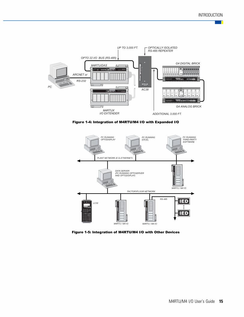
Available OptionsThe M4RTU/M4 I/O accommodates eight digital and four analog G4 I/O modules. For applications requiringadditional I/O modules, the Modular Controller product line includes a Modular Controller I/O Extender, calledthe M4RTUX, which connects to the M4RTU/M4 I/O base unit using an Opto 22 shielded 25-pin M4RTUXCABcable. The M4RTUX provides an additional eight digital and four analog I/O channels. With the M4RTUX optionconnected to the M4RTU/M4 I/O base unit, up to 24 G4 I/O modules can be installed. Additional I/O can beconnected via an RS-485 serial link.
To accommodate a wide variety of applications, seven power supplies are available for the M4RTU/M4 I/O:four wide-input-range DC (12V, 24V, 48V, 125V), two wide-input-range AC (120V, 220V), and one line filter basefor connecting user-supplied power supplies. These fuse-protected power supplies feature input-to-outputisolation protection, a built-in EMI filter, and an on/off switch. They supply enough power to operate the M4RTU/M4 I/O base unit, three M4BUS expansion options, and I/O modules for both the base unit and the Modular M4Controller I/O Extender. They can also supply the current loop for analog current modules.
The M4BUS technology provides a variety of communication interface cards. M4RTU/M4 I/O options includeEthernet interface cards (M4SENETU and M4SENETC), an ARCNET® interface card (M4SARC), a serial (RS-232and RS-422/RS-485) interface card (M4SSER), a fiber optic ARCNET®card (M4SARCF) and a fiber optic ARCNET®
repeater card (M4SARCFR). These open options allow customers to share real-time data with telemetry-basedSCADA systems or network-based control and information systems. The available serial ports communicate atup to 115 K baud. These ports can be used to support additional I/O units, perform host communications,interface to a modem or transmit data to and from third-party devices. The Ethernet and ARCNET optionsenable you to connect the M4RTU/M4 I/O to other major system components using plantwide informationnetworks. All modular interface cards for serial communications or network connectivity are supported asstandard selections in the FactoryFloor software.
SoftwareM4RTU/M4 I/O configuration and program development are performed on a PC workstation through OptoControl,Opto 22’s PC-based graphical, flowchart language. OptoControl is easy to learn, easy to use, and is designed toharness all the power of Opto 22’s distributed, control hardware platform. One of the fundamental advantagesof OptoControl is its usability. Six months after you write an OptoControl program, you can come back to it andunderstand it. Four key features of OptoControl are:
• OptoControl’s flowchart programming environment, which provides a precise, graphical view of yourcontrol process.
• OptoControl’s “Strategy Tree,” which provides a graphical tree-like view of your control systemconfiguration.
• OptoControl’s animated debugger, which makes it easy to step through your process and see what’shappening at every point in your control program.
• OptoControl flowcharts, which can be packaged as subroutines to provide extensive code reusability.
INTRODUCTION

12 M4RTU/M4 I/O User’s Guide
Tank Farm
INTRODUCTION
All these tools can be live on your workstation at the same time, thanks to Window’s multitasking. This self-documenting control environment is further enhanced by the use of a plain English command set, and a longtagname database that is shared by all FactoryFloor components.
During development of your application, you can download your control strategy to the M4RTU/M4 I/O anddebug the program using the OptoControl debug mode. OptoDisplay, Opto 22’s operator interface package,uses the long tagname database generated by OptoControl to easily develop a graphical display of your process.
OptoControl’s built-in Software Developers Kit (SDK) allows custom software developers a direct interface toOpto 22 controllers from high level programming languages. OptoControl also provides open access to thedatabase for third-parties and custom developers through the use of OptoServer, and the communications-enabling technologies inherent in Windows. Using OptoServer, the data server that connects the controllernetwork with the PC-based FactoryFloor network, you can develop client/server architectures supporting anyDDE or OPC aware third-party applications.
The FactoryFloor software environment supports modems (direct, lease, and radio), two-way dial-up capability(host to M4RTU/M4 I/O, M4RTU/M4 I/O to host), and peer-to-peer communications. It also supports remotekernel downloading to flash memory, remote program downloading and debugging, and remote data uploadingand downloading.
POSSIBLE APPLICATIONS
Flexibility is a key feature of Opto 22’s Modular controllers. This flexibility enables the M4RTU/M4 I/O to beused in a wide range of applications, including SCADA, remote, distributive, stand alone, process control,tooling, communication, data acquisition, and OEM applications.
The following diagrams depict two common applications for the M4RTU/M4 I/O: a tank farm and a remoteplant management system. Both applications typically require process control and data acquisition to beperformed remotely.

M4RTU/M4 I/O User’s Guide 13
Remote Plant Management
INTRODUCTION
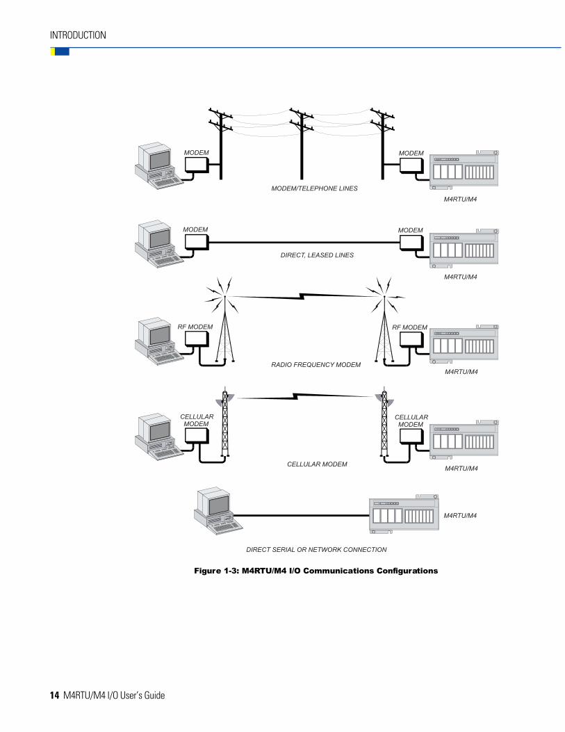
The M4RTU/M4 I/O is designed to be easy to configure in a variety of communication configurations, includingmodems connected to standard telephone lines, leased lines, radio frequency transceivers, and direct serialconnections to PC hardware.
The design of the M4RTU/M4 I/O is also conducive to integration with Opto 22’s digital and analog I/O systemsas well as with other intelligent equipment devices, such as industrial PCs, additional M4RTUs or other Opto 22controllers, subsystem automation gear, wastewater equipment, and various gas/petrochemical devices.See Figures 1-4 and 1-5.
Figure 1-2: Examples of M4RTU/M4 I/O Applications
14 M4RTU/M4 I/O User’s Guide
INTRODUCTION
Figure 1-3: M4RTU/M4 I/O Communications Configurations
M4RTU/M4 I/O User’s Guide 15
Figure 1-4: Integration of M4RTU/M4 I/O with Expanded I/O
Figure 1-5: Integration of M4RTU/M4 I/O with Other Devices
INTRODUCTION

16 M4RTU/M4 I/O User’s Guide
INTRODUCTION
BASIC ARCHITECTURE
The M4RTU/M4 I/O consolidates two powerful processors on a single processor board. Program control andhost communications are handled by a powerful 32-bit 68020 microprocessor, while a 16-bit 80C 196 processorhandles I/O interfacing and control. This dual-processor board is combined with a digital/analog I/O board,a 3-slot vertical expansion bus board (M4BUS), and a modular power supply into a compact aluminum extrusionpackage that can be mounted horizontally or vertically.
A block diagram of the M4RTU/M4 I/O is shown in Figure 1-6.
Figure 1-6: Block Diagram of M4RTU/M4 I/O
The powerful two-processor architecture allows the main processor to off-load onto the I/O processor suchtasks as counting, frequency and pulse measurement, latching, totalizing, time proportional output control,pulse generation, linearization, ramping, engineering unit conversion, averaging, peak and valley measurement,PID control, and event/reactions, to name a few. I/O control can continue even if the main processor fails orneeds to be reset.
Sophisticated reset circuitry and watchdog timer capability permit a user to develop intelligent, robust errorrecovery.
Finally, the M4BUS lays the foundation for intelligent coprocessor daughter cards. Armed with a processor,these daughter cards have the capability to interface to various industry hardware and software protocolswithout degrading overall real-time performance.

M4RTU/M4 I/O User’s Guide 17
INTRODUCTION
HARDWARE DIAGRAMS
M4RTU/M4 I/O Base Unit OverviewFigure 1-7 shows the basic components of the M4RTU/M4 I/O as viewed from the end of the unit with theexpansion slot and serial connector.
Figure1-7: M4RTU/M4 I/O as Viewed from End withExpansion Slot and Serial Connector

18 M4RTU/M4 I/O User’s Guide
INTRODUCTION
Figure 1-8 shows the basic components of the M4RTU/M4 I/O as viewed from the end of the unit with thepower supply and M4RTUX expansion connector.
Figure 1-8: M4RTU/M4 I/O as Viewed from End withPower Supply and M4RTUX Connectors
M4RTU/M4 I/O User’s Guide 19
QUICK START
OVERVIEW
This chapter provides a brief explanation of how to get the M4RTU/M4 I/O up and running. You may need torefer to the OptoControl User‘s Guide for detailed instructions. Also refer to appropriate chapters in this manualfor field wiring and communication setup instructions and diagrams.
A quick start installation consists of the following steps:
1. Unpacking the M4RTU/M4 I/O and power supply.
2. Installing the power supply.
3. Connecting the battery.
4. Checking configuration jumpers.
5. Installing optional expansion daughter cards and/or connecting cable to the I/O extender, as needed.
6. Mounting the M4RTU/M4 I/O.
7. Connecting to a host PC.
8. Verifying communications.
CHAPTER 2
20 M4RTU/M4 I/O User’s Guide
PACKING LIST
When removing the M4RTU/M4 I/O from its packaging, make sure the M4RTU/M4 I/O and the followingcomponents are included:
Component: Use:
• A bag of extra jumpers Can be installed as M4RTU/M4 I/Oconfiguration jumpers
• Two RS-485/RS-232 Connect wiring to serial ports7-position connectors
• Connector key disk, con- Prevents non-keyed connectors from pluggingtaining six connector keys into the serial port
• Mounting template Serves as a guide for preparing a mounting sitefor the M4RTU/M4 I/O
• Floppy disk (P/N 8886) Contains OptoControl firmware
• 2-Floppy disks (P/N 8848) Contains OptoUtilities, 32-bit utility used todownload OptoControl firmware
• Floppy disk (P/N 8887) Contains Cyrano firmware and DOS-utility todownload firmware
• Customer update sheet Contains latest product information
Note: If any of the above items is missing or damaged, contact Opto 22 immediately at 1-800-321-6786.
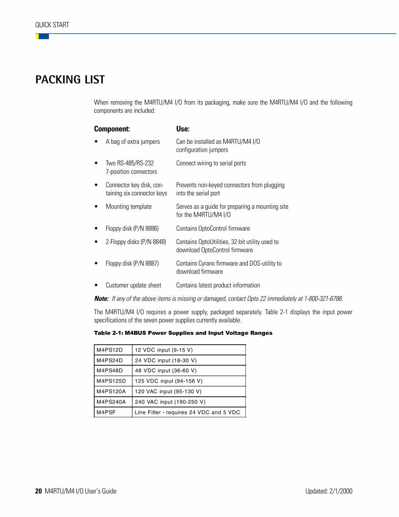
The M4RTU/M4 I/O requires a power supply, packaged separately. Table 2-1 displays the input powerspecifications of the seven power supplies currently available.
Table 2-1: M4BUS Power Supplies and Input Voltage Ranges
M4PS12D 12 VDC input (9-15 V)
M4PS24D 24 VDC input (18-30 V)
M4PS48D 48 VDC input (36-60 V)
M4PS125D 125 VDC input (94-156 V)
M4PS120A 120 VAC input (95-130 V)
M4PS240A 240 VAC input (190-250 V)
M4PSF Line Filter - requires 24 VDC and 5 VDC
QUICK START
Updated: 2/1/2000
M4RTU/M4 I/O User’s Guide 21
QUICK START
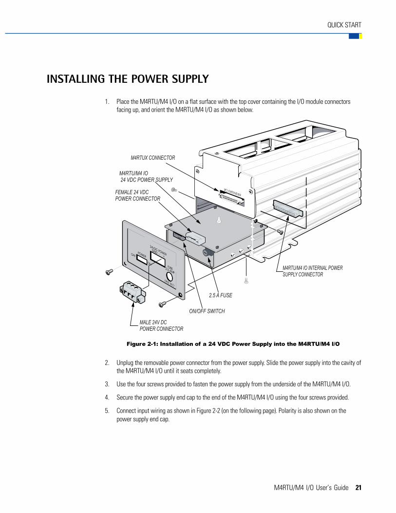
INSTALLING THE POWER SUPPLY
1. Place the M4RTU/M4 I/O on a flat surface with the top cover containing the I/O module connectorsfacing up, and orient the M4RTU/M4 I/O as shown below.
2. Unplug the removable power connector from the power supply. Slide the power supply into the cavity ofthe M4RTU/M4 I/O until it seats completely.
3. Use the four screws provided to fasten the power supply from the underside of the M4RTU/M4 I/O.
4. Secure the power supply end cap to the end of the M4RTU/M4 I/O using the four screws provided.
5. Connect input wiring as shown in Figure 2-2 (on the following page). Polarity is also shown on thepower supply end cap.
Figure 2-1: Installation of a 24 VDC Power Supply into the M4RTU/M4 I/O

22 M4RTU/M4 I/O User’s Guide
CONNECTING THE BATTERY
To save battery power, the M4RTU/M4 I/O backup battery is not connected at the factory. You will need toconnect it yourself. Refer to Figure 2-3 below to determine the location of the battery and its connection. Fordetailed information on connecting the battery, see Chapter 3.
QUICK START
Figure 2-2: VDC or VAC Power Connections on the M4RTU/M4 I/O
Figure 2-3: Location of Backup Battery on M4RTU/M4 I/O

M4RTU/M4 I/O User’s Guide 23
CHECKING CONFIGURATION JUMPERS
The M4RTU/M4 I/O configuration jumpers are already configured by the factory for connection to a host PCusing the M4RTU’s COM0 RS-232 serial port, set at a baud rate of 38.4 Kbps. The M4RTU/M4 I/O’s defaultaddress is 1and the default communication mode is binary. Refer to the figure below for the default configurationof all jumpers.
For a complete explanation of all configuration jumpers and switches, see “Setting Configuration Jumpers andSwitches” in Chapter 3. For a chart of address jumper configurations, see Appendix D.
INSTALLING DAUGHTER CARDS AND/OR I/O EXTENDER
If you have purchased optional expansion daughter cards for the M4RTU/M4 I/O, you will now need to installthem. Refer to the appropriate document listed below for detailed installation instructions:
• M4SSER — see M4 Serial Adapter Card Data Sheet (form 664)
• M4SARC — see M4 ARCNET Adapter Data Sheet (form 631)
• M4SARCF/M4SARCFR — see M4 ARCNET Adapter Fiber Optic Data Sheet and M4 ARCNET RepeaterFiber Optic Data Sheet (form 673)
• M4SENETU/M4SENETC — see M4SENETC and M4SENETU Data Sheet (form 718)
• M4DUALARC — see M4DUALARC Data Sheet (form 990)
In addition, if you have purchased the M4RTUX I/O Extender, it is advisable to install the M4RTUXCAB extendercable after installing daughter cards — but before mounting the M4RTU/M4 I/O. See Opto 22 Modular ControllerI/O Extender Data Sheet (form 671) for detailed instructions.
QUICK START
Figure 2-4: M4RTU/M4 I/O Configuration Jumpers

24 M4RTU/M4 I/O User’s Guide
QUICK START
MOUNTING THE M4RTU/M4 I/O
Affix the M4RTU/M4 I/O to an enclosure or panel, either vertically or horizontally, using the mountingflanges shown in Figure 2-5 below. Use the mounting template provided to prepare the mounting site.Using user-supplied 1/4-20 screws, fasten the M4RTU/M4 I/O via flanges to the panel.
Figure 2-5: M4RTU/M4 I/O Dimensions and Mounting Information

M4RTU/M4 I/O User’s Guide 25
CONNECTING TO A HOST PC
Wiring
RS-232 Pin Connections
The following diagram shows the pin positions for the M4RTU/M4 I/O COM0 serial port:
Refer to the table below to determine the function of each COM0 pin connection.
Table 2-2: Pin Connections for the M4RTU/M4 I/O COM0 Serial Port
1 Data Carrier Detect (DCD)
2 Transmit (TX)
3 Receive (RX)
4 Request-to-Send (RTS)
5 Clear-to-Send (CTS)
6 Data Terminal Ready (DTR)
7 Ground (GND)
QUICK START
Figure 2-6: RS-232 COM0 Pin Positions

26 M4RTU/M4 I/O User’s Guide
RS-232 Wiring Scheme
Use the default host port (COM0) of the M4RTU/M4 I/O to connect to the host PC. Follow the diagram below towire the M4RTU/M4 I/O RS-232 serial port to the serial connector on the PC. Verify that the pin connections atthe host PC are the same as those called out in the diagram.
Important: If RTS and CTS are not used, be sure to connect RTS to CTS on the M4RTU/M4 I/O as shownbelow.
Figure 2-7: RS-232 Wiring Scheme
QUICK START
M4RTU/M4 I/O User’s Guide 27
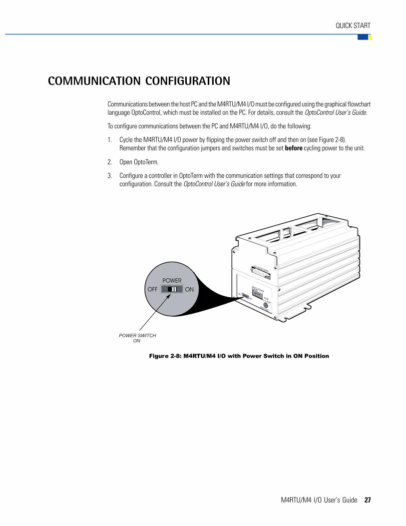
COMMUNICATION CONFIGURATION
Communications between the host PC and the M4RTU/M4 I/O must be configured using the graphical flowchartlanguage OptoControl, which must be installed on the PC. For details, consult the OptoControl User’s Guide.
To configure communications between the PC and M4RTU/M4 I/O, do the following:
1. Cycle the M4RTU/M4 I/O power by flipping the power switch off and then on (see Figure 2-8).Remember that the configuration jumpers and switches must be set before cycling power to the unit.
2. Open OptoTerm.
3. Configure a controller in OptoTerm with the communication settings that correspond to yourconfiguration. Consult the OptoControl User’s Guide for more information.
QUICK START
Figure 2-8: M4RTU/M4 I/O with Power Switch in ON Position

28 M4RTU/M4 I/O User’s Guide
VERIFYING COMMUNICATIONS
To verify communications between the M4RTU/M4I/O and the host PC, use the OptoTerm utility which isincluded with FactoryFloor. In OptoTerm, highlight the controller to communicate with, and then select VIEWand then STATUS from the menu bar. If the PC can successfully communicate with the M4 controller, a windowwill pop up on the PC screen which displays information about the M4 controller. Information such as the M4controller’s kernel version, the name of the current strategy, and the controller’s current date and time. If thecommunication is working correctly the time should update every one or two seconds, which can be verified byobserving the seconds portion of the time field.
If you have not established successful communications between the two devices:
• Make sure you powered down and powered up the M4RTU/M4 I/O after changing any configurationjumpers. Refer to Chapter 3 — Installation and Setup to verify wiring connections and jumper setting.
• Check PC hardware and the physical connection between the M4RTU/M4 I/O and the PC.
QUICK START
M4RTU/M4 I/O User’s Guide 29
INSTALLATION AND SETUP
OVERVIEW
This chapter expands upon the quick start information in Chapter 2 with detailed instructions on installing andconfiguring the base M4RTU/M4 I/O. It also introduces procedures for installing optional expansion cards andconnecting the optional M4RTUX Extender I/O unit. Detailed instructions on installing these optional units areprovided in each unit’s data sheet.
After unpacking the M4RTU/M4 I/O and power supply, review the packing list in Chapter 2 to ensure that allcomponents are included. You may then proceed through the installation procedures below, as detailed in thischapter:
• Installing the power supply
• Connecting the backup battery
• Setting configuration jumpers and switches
• (Optional) Installing expansion cards
• (Optional) Connecting the M4RTUXCAB cable to the M4RTU/M4 I/O base unit
• Mounting the M4RTU/M4 I/O base unit
• Connecting power to the M4RTU/M4 I/O
• Installing I/O modules
• Connecting field wiring
• Connecting to a host PC or modem
• (Optional) Connecting to Opto 22 I/O.
CHAPTER 3

30 M4RTU/M4 I/O User’s Guide
INSTALLATION AND SETUP
Figures 3-1 and 3-2 provide two views of the M4RTU/M4 I/O base unit, with all components clearly labeled.
Figure 3-2: M4RTU/M4 I/O as Viewed from End with Power Supplyand M4RTUX Connectors
Figure 3-1: M4RTU/M4 I/O as Viewed from End with Expansion Slotand Serial Connector
M4RTU/M4 I/O User’s Guide 31
INSTALLATION AND SETUP
INSTALLING THE POWER SUPPLY
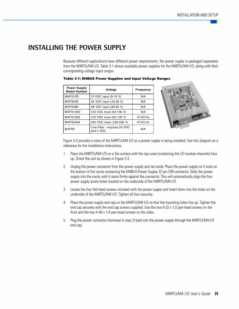
Because different applications have different power requirements, the power supply is packaged separatelyfrom the M4RTU/M4 I/O. Table 3-1 shows available power supplies for the M4RTU/M4 I/O, along with theircorresponding voltage input ranges.
Table 3-1: M4BUS Power Supplies and Input Voltage Ranges
Figure 3-3 provides a view of the M4RTU/M4 I/O as a power supply is being installed. Use this diagram as areference for the installation instructions.
1. Place the M4RTU/M4 I/O on a flat surface with the top cover (containing the I/O module channels) faceup. Orient the unit as shown in Figure 3-3.
2. Unplug the power connector from the power supply and set aside. Place the power supply so it rests onthe bottom of the cavity containing the M4BUS Power Supply 32-pin DIN connector. Slide the powersupply into the cavity until it seats firmly against the connector. This will automatically align the fourpower supply screw holes located on the underside of the M4RTU/M4 I/O.
3. Locate the four flat-head screws included with the power supply and insert them into the holes on theunderside of the M4RTU/M4 I/O. Tighten all four securely.
4. Place the power supply end cap on the M4RTU/M4 I/O so that the mounting holes line up. Tighten theend cap securely with the end cap screws supplied. Use the two 8-32 x 1/2 pan-head screws on thefront and the two 4-40 x 1/4 pan-head screws on the sides.
5. Plug the power connector (removed in step 2) back into the power supply through the M4RTU/M4 I/Oend cap.
Power SupplyModel Number
Voltage Frequency
M4PS12D 12 VDC input (9-15 V) N/A
M4PS24D 24 VDC input (18-30 V) N/A
M4PS48D 48 VDC input (36-60 V) N/A
M4PS125D 125 VDC input (94-156 V) N/A
M4PS120A 120 VDC input (95-130 V) 47-63 Hz
M4PS240A 240 VDC input (190-250 V) 47-63 Hz
M4PSFLine Filter - requires 24 VDCand 5 VDC
N/A

32 M4RTU/M4 I/O User’s Guide
INSTALLATION AND SETUP
Figure 3-3: Installing the Power Supply on the M4RTU/M4 I/O

M4RTU/M4 I/O User’s Guide 33
INSTALLATION AND SETUP
CONNECTING THE BACKUP BATTERY
The M4RTU/M4 I/O includes a RAM backup battery. This 3.6-volt lithium battery features a shelf life of up to10 years and an operational life of two to five years.
To maintain operational life, the battery is not connected at the factory. You will need to connect it yourself.To do so, remove the top cover of the M4RTU/M4 I/O by removing the four corner screws. The battery is locatedat the far right of the unit. Attach the battery connection wire to the battery connection labeled J2. The connectionwire will attach in one direction only, with the red wire connecting to the positive lead. Refer to Figure 3-4 toconfirm battery and battery connection locations.
The Battery Service Record stamp adjacent to the J2 battery connection includes the Opto 22 part number ofthe battery (G4BATT32), the date the battery was installed, and the date the battery should be replaced(five years after installation). If the M4RTU/M4 I/O is subjected to temperature extremes, you should replacethe battery after as little as two years.
To comply with Factory Mutual, section 3.2.7, replacement of the lithium battery must be done by the factory.
Figure 3-4: M4RTU/M4 I/O Backup Battery Location

34 M4RTU/M4 I/O User’s Guide
INSTALLATION AND SETUP
SETTING CONFIGURATION JUMPERS AND SWITCHES
The M4RTU/M4 I/O includes jumpers and switches that allow you to configure the M4RTU/M4 I/O based onyour individual application requirements. This section describes these configuration jumpers and switches.
I/O Board JumpersFigure 3-5 shows the location of 18 of the 21 M4RTU/M4 I/O jumpers. To access these jumpers, remove the topcover of the M4RTU/M4 I/O by removing the four corner screws. Note that a sticker is affixed to the undersideof the cover to summarize the function of these jumpers.
Table 3-2 describes the use and default settings of all I/O board jumpers. When a jumper is installed, thesetting corresponding to the “In” position is in effect. When a jumper is not installed, the setting correspondingto the “Out” position is in effect.
Each jumper is described in detail on the following pages.
Figure 3-5: Configuration Jumpers on the M4RTU/M4 I/O Board
M4RTU/M4 I/O User’s Guide 35
INSTALLATION AND SETUP
Table 3-2: M4RTU/M4 I/O Board Jumpers (factory defaults are highlighted)
Jumper(s) Description Position Setting
E/R EEPROM/RAM
In Run from RAM
OutRun fromEEPROM
Auto Autoboot
In Autoboot enabled
Out Autobootdisabled
X0 CommunicationIn Binary
Out ASCII
X1 Boot LoaderIn Boot to kernel
Out Boot to loader
H0, H1 Host Port
H0 H1
In In COM0
Out In COM1
In Out ARCNET
Out Out Ethernet
Baud 0-3 Baud Rate
0 1 2 3
Out In In In 115.2 KBd
In Out In In 76.8 KBd
Out Out In In 57.6 KBd
In In Out In 38.4 KBd
Out In Out In 19.2 KBd
In Out Out In 9600 Bd
Out Out Out In 4800 Bd
In In In Out 2400 Bd
Out In In Out 1200 Bd
In Out In Out 600 Bd
Out Out In Out 300 Bd
Address 0-7 Address Bits
Bit 0 In 1
Bit 1 In 2
Bit 2 In 4
Bit 3 In 8
Bit 4 In 16
Bit 5 In 32
Bit 6 In 64
Bit 7 In 128

36 M4RTU/M4 I/O User’s Guide
INSTALLATION AND SETUP
EEPROM/RAM Jumper (E/R)
Use this jumper to choose the source of the M4RTU/M4 I/O’s control program. When the jumper is in(the default), the control program will run from RAM; when the jumper is out, the control program is copied fromFlash EEPROM into RAM and run from RAM.
Normally, application programs are downloaded from your PC workstation to battery-backed CMOS RAM in theM4RTU/M4 I/O. The programs are then executed from RAM. Unless application programs are stored in FlashEEPROM, the E/R jumper should be installed to allow the control program in RAM to run.
Autoboot Jumper (AUTO)
Use this jumper to determine whether autoboot mode will be enabled (jumper in) or disabled (jumper out,the default).
When autoboot mode is enabled, at power-up the M4RTU/M4 I/O automatically executes the resident userprogram (RAM or Flash). Otherwise, it waits to receive a command to run the resident program.
Communication Mode Jumper (X0)
Use this jumper to select whether communication between the host computer and the controller will be inbinary mode (jumper in, the default) or ASCII mode (jumper out). Generally, ASCII mode is used in applicationsrequiring a modem. For ARCNET or Ethernet this jumper is ignored. For more detailed information, refer to theOptoControl Command Reference Manual — Communications Overview.
Boot Loader Jumper (X1)
Use this jumper to set the controller to either boot to the downloaded kernel (jumper in, the default) or boot toloader (jumper out). This jumper should always remain in place for normal operations. For more information,see Appendix A (Troubleshooting).
Host Port Jumpers (H0, H1)
Use these jumpers to determine the primary host port used by the M4RTU/M4 I/O upon power-up or reset.Select from COM0 (both jumpers in, the default), COM1 (H0 jumper out, H1 jumper in), ARCNET (H0 jumper in,H1 jumper out), or Ethernet (both jumpers out).
COM0 is dedicated for RS-232 communications and COM1 is dedicated for RS-485 communications. SelectARCNET only if an optional M4SARC, M4SARCF, or M4SARCFR ARCNET expansion card is installed. SelectEthernet only if an optional M4SENETU or M4SENETC expansion card is installed.
Baud Rate Jumpers (BAUD 0–3)
Use these jumpers to set the baud rate for the host serial port (COM0 or COM1) on power-up or reset. Select theappropriate jumper settings based on the baud rates in Table 3-2. (These baud rates also appear on the stickeron the underside of the M4RTU/M4 I/O’s top cover.) The default baud rate is 38.4 Kbps.
Note that if an optional ARCNET or Ethernet expansion card is installed and ARCNET or Ethernet is configuredas the host, the baud rate jumper settings are irrelevant.

M4RTU/M4 I/O User’s Guide 37
INSTALLATION AND SETUP
Use the Configure Controllers - Setup Controller Ports dialog box in OptoControl to set the baud rate for anyM4RTU/M4 I/O serial port that is not being used as the primary host port. Consult the OptoControl User’s Guidefor more information.
Address Jumpers (ADDRESS 0–7)
Use these jumpers to select an 8-bit address from one to 255 (one to FF hexadecimal). The factory default is one(jumper zero in, all others out). The most significant bit is seven and the least significant bit is zero; address zerois reserved and should not used. Refer to Figure 3-6.
Processor Board JumpersFour additional jumpers are located on the main processor board, as shown below. For details on accessingthese jumpers, see Appendix E (Upgrading RAM and Flash EEPROM).
Table 3-3 describes the use and default settings of all jumpers. When a jumper is installed, the settingcorresponding to the “In” position is in effect. When a jumper is not installed, the setting corresponding to the“Out” position is in effect.
Each jumper is described in detail on the following pages.
Figure 3-6: Address Jumper Setting
38 M4RTU/M4 I/O User’s Guide
INSTALLATION AND SETUP
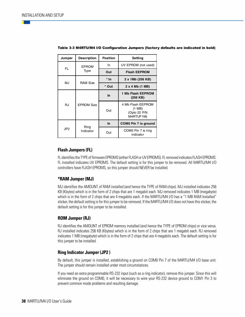
Table 3-3 M4RTU/M4 I/O Configuration Jumpers (factory defaults are indicated in bold)
Flash Jumpers (FL)
FL identifies the TYPE of firmware EPROMS (either FLASH or UV EPROMS). FL removed indicates FLASH EPROMS.FL installed indicates UV EPROMS. The default setting is for this jumper to be removed. All M4RTU/M4 I/Ocontrollers have FLASH EPROMS, so this jumper should NEVER be installed.
*RAM Jumper (MJ)
MJ identifies the AMOUNT of RAM installed (and hence the TYPE of RAM chips). MJ installed indicates 256KB (Kbytes) which is in the form of 2 chips that are 1 megabit each. MJ removed indicates 1 MB (megabyte)which is in the form of 2 chips that are 4 megabits each. If the M4RTU/M4 I/O has a “1 MB RAM Installed”sticker, the default setting is for this jumper to be removed. If the M4RTU/M4 I/O does not have this sticker, thedefault setting is for this jumper to be installed.
ROM Jumper (RJ)
RJ identifies the AMOUNT of EPROM memory installed (and hence the TYPE of EPROM chips) or vice versa.RJ installed indicates 256 KB (Kbytes) which is in the form of 2 chips that are 1 megabit each. RJ removedindicates 1 MB (megabyte) which is in the form of 2 chips that are 4 megabits each. The default setting is forthis jumper to be installed.
Ring Indicator Jumper (JP2 )
By default, this jumper is installed, establishing a ground on COM0 Pin 7 of the M4RTU/M4 I/O base unit.The jumper should remain installed under most circumstances.
If you need an extra programmable RS-232 input (such as a ring indicator), remove this jumper. Since this willeliminate the ground on COM0, it will be necessary to wire your RS-232 device ground to COM1 Pin 3 toprevent common mode problems and resulting damage.
Jumper Description Position Setting
FLEPROM
Type
In UV EPROM (not used)
Out Flash EEPROM
MJ RAM Size* In 2 x 1Mb (256 KB)
* Out 2 x 4 Mb (1 MB)
RJ EPROM Size
In1 Mb Flash EEPROM
(256 KB)
Out
4 Mb Flash EEPROM(1 MB)
(Opto 22 P/NM4RTUF1M)
JP2Ring
Indicator
In COM0 Pin 7 is ground
OutCOM0 Pin 7 is ring
indicator
M4RTU/M4 I/O User’s Guide 39
INSTALLATION AND SETUP
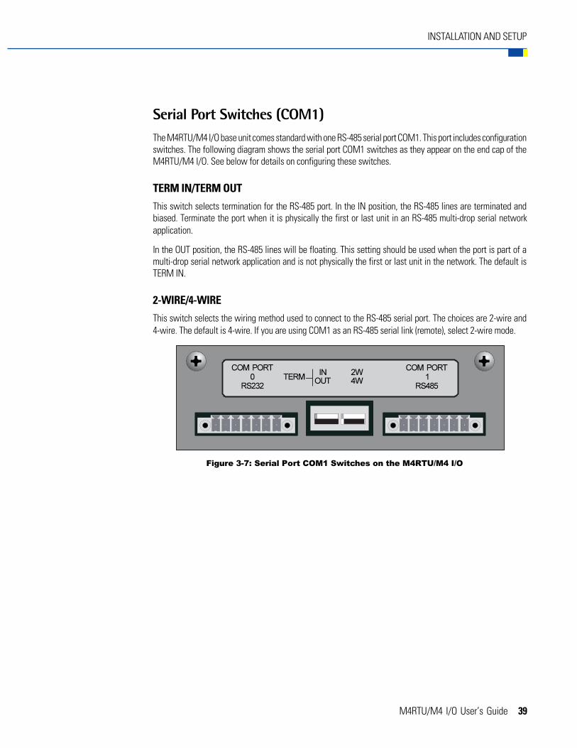
Serial Port Switches (COM1)The M4RTU/M4 I/O base unit comes standard with one RS-485 serial port COM1. This port includes configurationswitches. The following diagram shows the serial port COM1 switches as they appear on the end cap of theM4RTU/M4 I/O. See below for details on configuring these switches.
TERM IN/TERM OUT
This switch selects termination for the RS-485 port. In the IN position, the RS-485 lines are terminated andbiased. Terminate the port when it is physically the first or last unit in an RS-485 multi-drop serial networkapplication.
In the OUT position, the RS-485 lines will be floating. This setting should be used when the port is part of amulti-drop serial network application and is not physically the first or last unit in the network. The default isTERM IN.
2-WIRE/4-WIRE
This switch selects the wiring method used to connect to the RS-485 serial port. The choices are 2-wire and4-wire. The default is 4-wire. If you are using COM1 as an RS-485 serial link (remote), select 2-wire mode.
Figure 3-7: Serial Port COM1 Switches on the M4RTU/M4 I/O

40 M4RTU/M4 I/O User’s Guide
INSTALLATION AND SETUP
INSTALLING EXPANSION CARDS
If you purchased expansion cards, you will need to install them in the M4RTU/M4 I/O before mounting the baseunit.
The general procedure for installing optional cards is as follows:
1. If installed, remove the power connector from M4RTU/M4 I/O power supply.
2. Remove the end cap for any of the three expansion slots, located below the M4RTU/M4 I/O base unitserial connectors. Each end cap is held in place by two screws located on the side panel, adjacent toeach end cap. (You may also need to remove one or two additional end caps to achieve proper cardalignment.)
3. Align the edges of the card with the U-channels on the sides of the expansion bus cavity. Slide the cardall the way in until it seats into the M4RTU/M4 I/O bus connector.
4. Use the original screws to attach the new end cap (included with the card) to the end of the M4RTU/M4 I/O unit.
See Figure 3-8 for reference. For complete details on installing the M4SSER, see M4 Serial Adapter Card DataSheet (form 664). For details on installing expansion cards, see the appropriate expansion card data sheet.The form numbers can be found in Chapter 2, page 23 of this manual.
Figure 3-8: Installing an Expansion Card into the M4RTU/M4 I/O Expansion Slot

M4RTU/M4 I/O User’s Guide 41
INSTALLATION AND SETUP
CONNECTING THE M4RTUXCABCABLE TO THE M4RTU/M4 I/O BASE UNIT
The optional M4RTUX I/O Extender Unit expands the number of input/output points available to the M4RTU/M4 I/O from eight digital and four analog to 16 digital and eight analog.
If you plan to install the M4RTUX, you should attach the connecting cable (the M4RTUXCAB, packaged with theM4RTUX) to the M4RTU/M4 I/O before mounting the base unit. You can then elect to mount the extender unitright away or at some later time.
Brief procedures for connecting the M4RTUXCAB cable are provided below, along with a diagram illustratingwhere the cable should be attached. For complete details on installing the M4RTUX, see Modular ControllerI/O Extender Data Sheet (form 671).
1. Locate the I/O Extender connector. This 25-pin D-shell connector can be found on the same end of theM4RTU/M4 I/O as the power supply connector.
2. Align the M4RTUXCAB connector with the I/O Extender connector on the base unit and seat properly.
3. Tighten the M4RTUXCAB connector locking screws to secure the cable to the base unit.
Figure 3-9: M4RTUXCAB Cable Connected to the M4RTU/M4 I/O Base Unit

42 M4RTU/M4 I/O User’s Guide
INSTALLATION AND SETUP
MOUNTING THE M4RTU/M4 I/O BASE UNIT
Two flanges are located on the upper right and lower left back sides of the M4RTU/M4 I/O. Each flange has twomounting slots that can be used to fasten the M4RTU/M4 I/O to any enclosure or panel, either vertically orhorizontally.
Note: Be sure to install the power supply, any optional expansion cards, and the M4RTUXCAB on the M4RTU/M4 I/O before mounting the unit.
The general procedure for mounting the M4RTU/M4 I/O base unit is as follows:
1. Determine panel mounting site and orientation (horizontal or vertical). Be sure to allow room forexternal connectors.
2. Tape the supplied mounting template onto the M4RTU/M4 I/O panel and prick-punch mountinglocations.
3. Remove template and drill preliminary pilot holes.
4. Drill and tap (or drill through holes) for 1/4-20 screws.
5. Place M4RTU/M4 I/O onto mounting site and fasten with user-supplied 1/4-20 screws or screw and nutassemblies.

M4RTU/M4 I/O User’s Guide 43
INSTALLATION AND SETUP
Figure 3-10: M4RTU/M4 I/O Dimensions and Mounting Information

44 M4RTU/M4 I/O User’s Guide
INSTALLATION AND SETUP
CONNECTING POWER TO THE M4RTU/M4 I/O
Once you have mounted the M4RTU/M4 I/O, you are ready to connect power to the unit. Refer to Figure 3-11.
1. Turn off the power supply switch.
2. Make sure all power supply terminal block connections are completely open by turning the powerterminal screws counterclockwise.
3. Prepare each power supply wire, being careful not to strip back the insulation too far.
4. Insert each wire into the appropriate terminal block location and tighten by turning the power terminalscrew clockwise. Make sure the terminal block is clamping the wire and not the insulation.
5. Tighten power connector locking screws.
Note that steps 2–4 may be performed with the power supply connector removed from the power supply. Oncesteps 2–4 are complete, plug the power supply connector back into the M4RTU/M4 I/O and proceed to step 5.
Figure 3-11: Connecting Power to the M4RTU/M4 I/O
M4RTU/M4 I/O User’s Guide 45
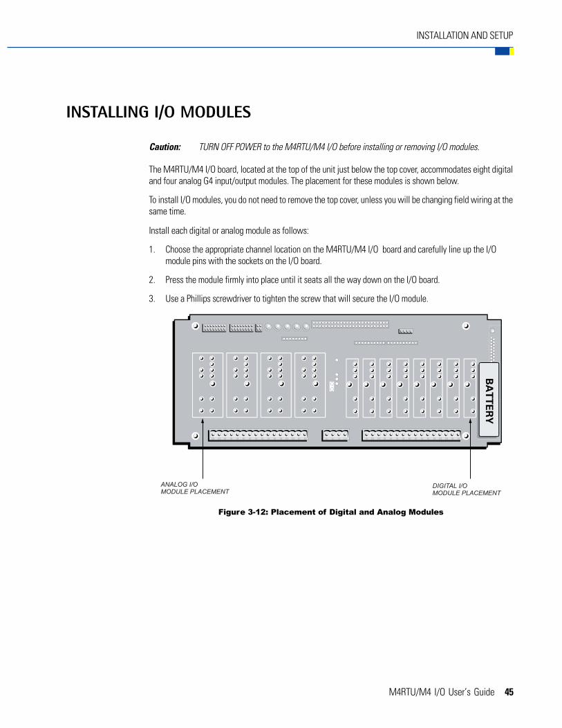
INSTALLATION AND SETUP
INSTALLING I/O MODULES
Caution: TURN OFF POWER to the M4RTU/M4 I/O before installing or removing I/O modules.
The M4RTU/M4 I/O board, located at the top of the unit just below the top cover, accommodates eight digitaland four analog G4 input/output modules. The placement for these modules is shown below.
To install I/O modules, you do not need to remove the top cover, unless you will be changing field wiring at thesame time.
Install each digital or analog module as follows:
1. Choose the appropriate channel location on the M4RTU/M4 I/O board and carefully line up the I/Omodule pins with the sockets on the I/O board.
2. Press the module firmly into place until it seats all the way down on the I/O board.
3. Use a Phillips screwdriver to tighten the screw that will secure the I/O module.
Figure 3-12: Placement of Digital and Analog Modules

46 M4RTU/M4 I/O User’s Guide
INSTALLATION AND SETUP
CONNECTING FIELD WIRING
To access the field wiring terminals, you will first need to remove the top cover of the M4RTU/M4 I/O byremoving the four corner screws at the top of the unit.
The pluggable field wiring terminals are located on the top of the M4RTU/M4 I/O board next to the correspondingdigital or analog channels. These terminals allow field wires to be connected to the installed I/O modules.
Figure 3-13 shows the location of the terminals on the unit and the layout of the terminal points as theycorrespond to each I/O module.
Specific information on wiring digital and analog modules follows. For more detailed wiring information,refer to Chapter 5 (Field Wiring).
Figure 3-13: Locations of Terminals on the M4RTU/M4 I/O

M4RTU/M4 I/O User’s Guide 47
INSTALLATION AND SETUP
Digital ModulesDigital modules have two terminals corresponding to each module. Figure 3-14 shows a G4IDC5 digital inputmodule in channel zero wired with VIN + on terminal #1 and VIN - on terminal #2.
Analog ModulesAnalog modules can use up to four terminals per I/O point. Figure 3-15 shows a G4AD6 0-5 VDC analog inputmodule in channel zero wired with VIN - on terminal #2 and VIN + on terminal #4. Refer to Chapter 5 for wiringother analog modules.
Figure 3-14: Digital Module Terminals
Figure 3-15: Wiring for Analog Module G4AD6
48 M4RTU/M4 I/O User’s Guide
INSTALLATION AND SETUP
CONNECTING TO A HOST PC OR MODEM
The M4RTU/M4 I/O features two built-in serial ports, COM0 (RS-232) and COM1 (RS-485), with a data transferrate of 300 Bd to 115.2 Kbps. Two additional serial ports are available by installing an optional M4SSER serialexpansion card into one of the M4RTU/M4 I/O expansion card slots. (See Chapter 4 for complete information.)
Wiring
Important: Serial port connectors wired for other Opto 22 controllers may not be compatible with the M4RTU/M4 I/O. Use the M4RTU/M4 I/O connectors provided and refer to the diagrams in this manualfor wiring information.
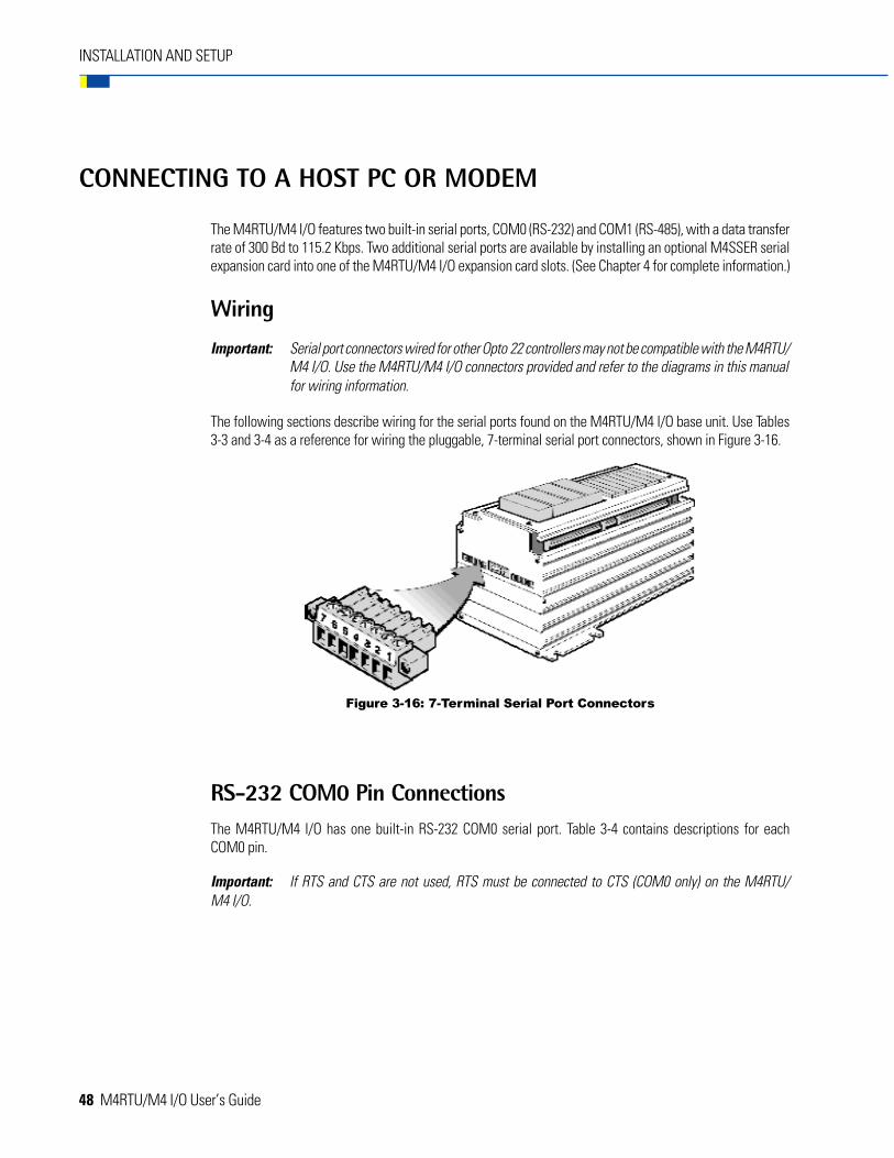
The following sections describe wiring for the serial ports found on the M4RTU/M4 I/O base unit. Use Tables3-3 and 3-4 as a reference for wiring the pluggable, 7-terminal serial port connectors, shown in Figure 3-16.
RS-232 COM0 Pin ConnectionsThe M4RTU/M4 I/O has one built-in RS-232 COM0 serial port. Table 3-4 contains descriptions for eachCOM0 pin.
Important: If RTS and CTS are not used, RTS must be connected to CTS (COM0 only) on the M4RTU/M4 I/O.
Figure 3-16: 7-Terminal Serial Port Connectors

M4RTU/M4 I/O User’s Guide 49
INSTALLATION AND SETUP
PIN CONNECTIONS/DESCRIPTIONS
Table 3-4: Pin Descriptions for the M4RTU/M4 I/O COM0 Serial Port
Pin COM0
1 Data Carrier Detect (DCD)
2 Transmit (TX)
3 Receive (RX)
4 Request-to-Send (RTS)
5 Clear-to-Send (CTS)
6 Data Terminal Ready (DTR)
7 Ground (GND)
RS-485 COM1 Pin ConnectionsAn RS-485 COM1 port is also built into the M4RTU/M4 I/O base unit. Table 3-5 contains descriptions for eachCOM1 pin for both 2-wire and 4-wire modes.
Note that the interrupt lines can be used to add interrupt capability to Opto 22 I/O units connected to anM4RTU/M4 I/O via an RS-485 serial link (remote).
Table 3-5: Pin Descriptions for the M4RTU/M4 I/O COM1 Serial Port
Pin 2-wire Mode 4-wire Mode
1 Transmit/Receive Plus (TX/RX +) Transmit Plus (TX +)
2 Transmit/Receive Minus (TX/RX -) Transmit Minus (TX -)
3 Common Ground (GND) Common Ground (GND)
4 No Connection (N/C) Receive Plus (RX +)
5 No Connection (N/C) Receive Minus (RX -)
6 Interrupt Plus (IRQ +) Interrupt Plus (IRQ +)
7 Interrupt Minus (IRQ -) Interrupt Minus (IRQ -)

50 M4RTU/M4 I/O User’s Guide
INSTALLATION AND SETUP
Wiring to a Host PCThis section provides information on wiring connections between an M4RTU/M4 I/O and a host personalcomputer. Examples show connections to a standard PC serial port and an Opto 22 AC37.
Be sure to use cable appropriate to your application. See Appendix B for a complete list of recommendedcables.
RS-232 COM0
Make RS-232 communication connections to a host PC by using the RS-232 COM0 default host connector onthe M4RTU/M4 I/O.
Refer to Figure 3-17 to connect the M4RTU/M4 I/O to the serial port of a host PC. Verify that the pin connectionsat the host PC are the same as those called out in the diagram.
Important: If RTS and CTS are not used, RTS must be connected to CTS (COM0 only) on the M4RTU/M4I/O, as shown below.
Figure 3-17: RS-232 Wiring to a Host PC
M4RTU/M4 I/O User’s Guide 51
INSTALLATION AND SETUP
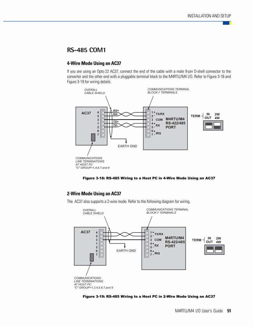
RS-485 COM1
4-Wire Mode Using an AC37
If you are using an Opto 22 AC37, connect the end of the cable with a male 9-pin D-shell connector to theconverter and the other end with a pluggable terminal block to the M4RTU/M4 I/O. Refer to Figure 3-18 andFigure 3-19 for wiring details.
2-Wire Mode Using an AC37
The AC37 also supports a 2-wire mode. Refer to the following diagram for wiring.
Figure 3-18: RS-485 Wiring to a Host PC in 4-Wire Mode Using an AC37
Figure 3-19: RS-485 Wiring to a Host PC in 2-Wire Mode Using an AC37
52 M4RTU/M4 I/O User’s Guide
INSTALLATION AND SETUP
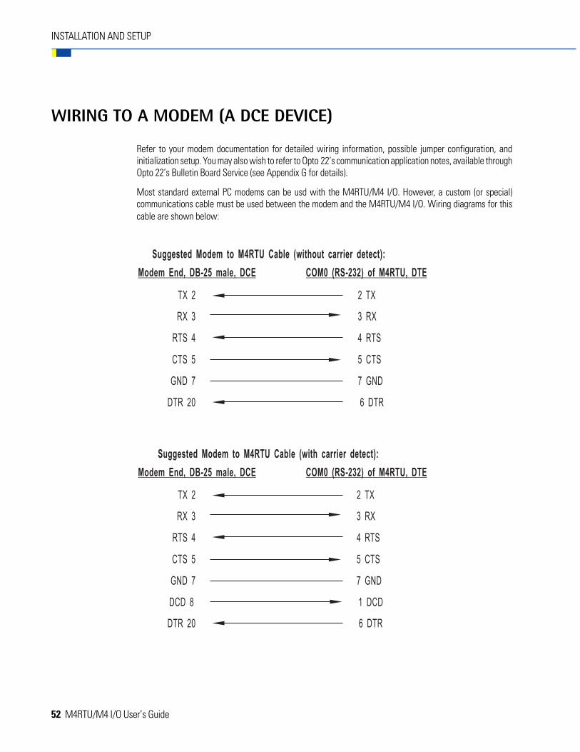
WIRING TO A MODEM (A DCE DEVICE)
Refer to your modem documentation for detailed wiring information, possible jumper configuration, andinitialization setup. You may also wish to refer to Opto 22’s communication application notes, available throughOpto 22’s Bulletin Board Service (see Appendix G for details).
Most standard external PC modems can be usd with the M4RTU/M4 I/O. However, a custom (or special)communications cable must be used between the modem and the M4RTU/M4 I/O. Wiring diagrams for thiscable are shown below:
M4RTU/M4 I/O User’s Guide 53
INSTALLATION AND SETUP
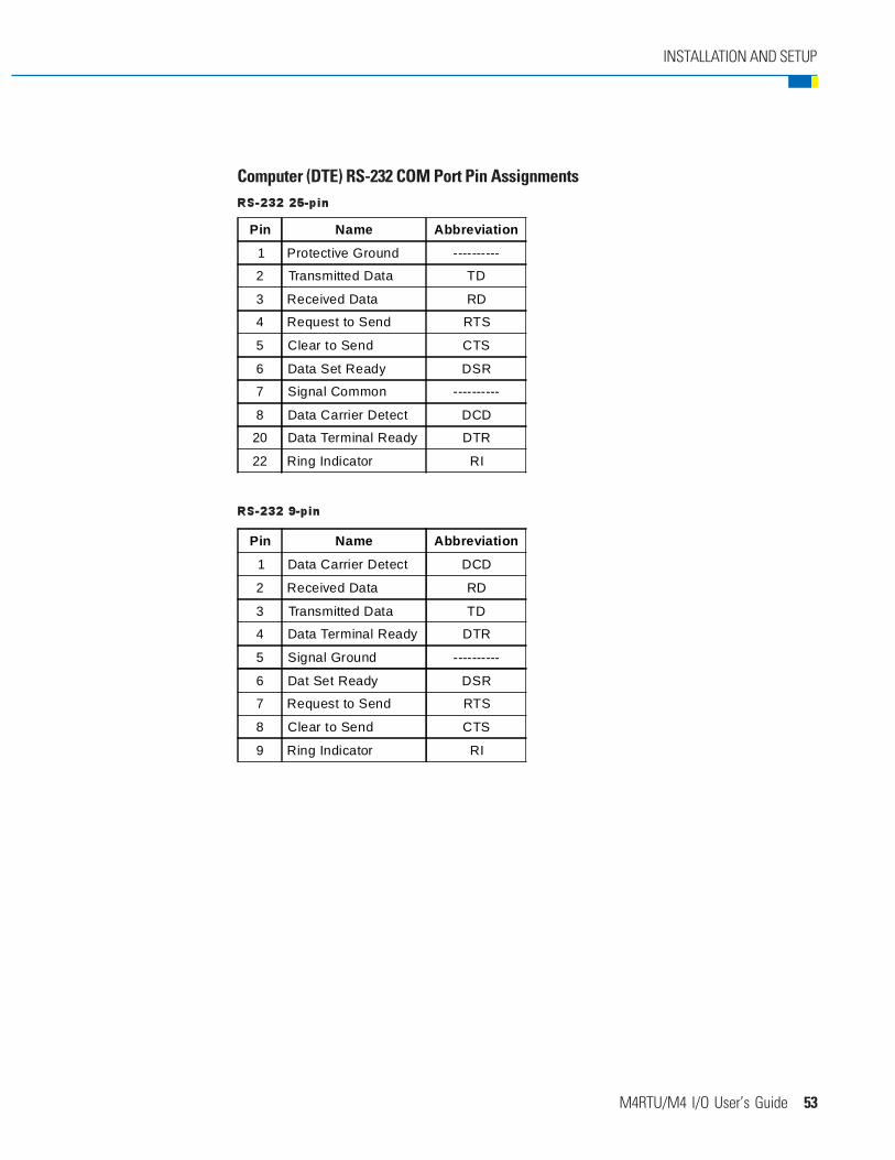
Computer (DTE) RS-232 COM Port Pin AssignmentsRS-232 25-pin
Pin Name Abbreviation
1 Protective Ground ----------
2 Transmitted Data TD
3 Received Data RD
4 Request to Send RTS
5 Clear to Send CTS
6 Data Set Ready DSR
7 Signal Common ----------
8 Data Carrier Detect DCD
20 Data Terminal Ready DTR
22 Ring Indicator RI
RS-232 9-pin
Pin Name Abbreviation
1 Data Carrier Detect DCD
2 Received Data RD
3 Transmitted Data TD
4 Data Terminal Ready DTR
5 Signal Ground ----------
6 Dat Set Ready DSR
7 Request to Send RTS
8 Clear to Send CTS
9 Ring Indicator RI

54 M4RTU/M4 I/O User’s Guide
INSTALLATION AND SETUP
CONNECTING TO OPTO 22 I/O UNITS
The built-in RS-485 COM1 port can be used as a serial link (remote) to communicate with Opto 22 digital oranalog I/O. A M4SSER serial expansion card installed in the M4RTU/M4 I/O can also be used for this purpose.
One method for doing this is to use a Mistic 200 I/O Remote Interface board (G4IOR) as illustrated in Figure3-20. This method allows the use of Opto 22 I/O equipment (G4 panels, cables, etc.).
Figure 3-20 shows a 2-wire RS-485 shielded connection from COM1 on the M4RTU/M4 I/O to the G4IORRemote Interface board. Connect Pin 1 (TX/RX+) to G4IOR “TH+,” Pin 2 (TX/RX-) to G4IOR “TH-,” and Pin 3 to“COM.” If you are using the interrupt lines, connect Pin 6 to “IRQ+” and Pin 7 to “IRQ-.”
Figure 3-20: Communications to a Remote Interface (G4IOR)
Note: Refer to cablespecifications inAppendix B.
Updated: 12/18/00

M4RTU/M4 I/O User’s Guide 55
INSTALLATION AND SETUP
Another method for using the RS-485 COM1 port as an RS-485 serial link (remote) is to use Opto 22 I/O unitsinstalled with a SBTA, as illustrated in Figure 3-21. This allows you to accommodate your own installationpractices, application requirements, and cables. Simply mount your I/O units throughout your installation anddaisy chain communication cable between them. Refer to the Mistic 200 Systems Installation Guide for moreSBTA details.
Figure 3-21: Opto 22 I/O Units Installed with SBTA
Note: Refer to cablespecifications in
Appendix B.
Updated: 12/18/00
56 M4RTU/M4 I/O User’s Guide
INSTALLATION AND SETUP
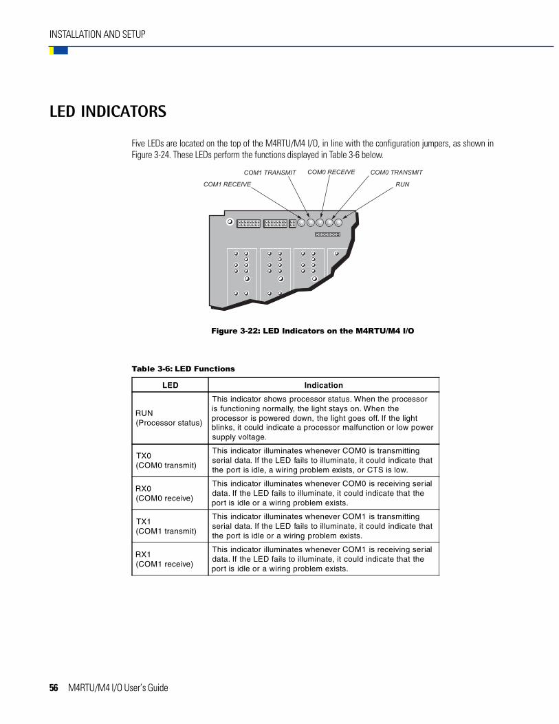
LED INDICATORS
Five LEDs are located on the top of the M4RTU/M4 I/O, in line with the configuration jumpers, as shown inFigure 3-24. These LEDs perform the functions displayed in Table 3-6 below.
Table 3-6: LED Functions
LED Indication
RUN(Processor status)
This indicator shows processor status. When the processoris functioning normally, the light stays on. When theprocessor is powered down, the light goes off. If the lightblinks, it could indicate a processor malfunction or low powersupply voltage.
TX0(COM0 transmit)
This indicator illuminates whenever COM0 is transmittingserial data. If the LED fails to illuminate, it could indicate thatthe port is idle, a wiring problem exists, or CTS is low.
RX0(COM0 receive)
This indicator illuminates whenever COM0 is receiving serialdata. If the LED fails to illuminate, it could indicate that theport is idle or a wiring problem exists.
TX1(COM1 transmit)
This indicator illuminates whenever COM1 is transmittingserial data. If the LED fails to illuminate, it could indicate thatthe port is idle or a wiring problem exists.
RX1(COM1 receive)
This indicator illuminates whenever COM1 is receiving serialdata. If the LED fails to illuminate, it could indicate that theport is idle or a wiring problem exists.
Figure 3-22: LED Indicators on the M4RTU/M4 I/O

M4RTU/M4 I/O User’s Guide 57
SOFTWARE AND FIRMWARE
OVERVIEW
This chapter provides information on using OptoControl, OptoDisplay, and OptoServer with the M4RTU/M4 I/O.OptoControl is used to program and debug M4RTU/M4 I/O control strategies. OptoDisplay is used to createM4RTU/M4 I/O process operator interfaces running on the PC. OptoServer allows the user to construct complexclient/server architectures running multiple OptoDisplay sessions, DDE-aware applications (such as MicrosoftExcel), or third-party software packages with OptoServer driver capability. The tight integration betweenOptoControl, OptoDisplay, and OptoServer not only makes all three software packages easy to use, it alsoprevents multiple database entry errors, allows tag name validation, and takes full advantage of the M4RTU/M4 I/O’s hardware capabilities.
The sophisticated firmware of both the main and I/O processors of the M4RTU/M4 I/O, along with flashtechnology, enables a user to update the M4RTU/M4 I/O remotely with a new set of operating systems for themain and I/O processors. The firmware also supports the ability to store a user’s strategy permanently intoflash memory.
Note: It is not the intent of this chapter to teach OptoControl programming and debugging, OptoDisplayconfiguration and runtime operation, or overall OptoServer usage. Instead, this chapter presentsan overview of these topics, with enough details to get you started. For detailed information on thesesubjects, refer to the appropriate Opto 22 user guides.
CHAPTER 4

58 M4RTU/M4 I/O User’s Guide
OPTOCONTROL
OptoControl is used to configure communications between the PC and the M4RTU/M4 I/O, configure the I/Ounits and points, and develop and run your control strategy.
Configuring Communications to the M4RTU/M4 I/O
To download OptoControl strategies to the M4RTU/M4 I/O and debug them, you must first configure thecommunication link between the host PC and the M4RTU/M4 I/O. Begin by deciding what type of physicalcommunication link will be used (ARCNET, RS-232, RS-485/422, or Ethernet). Next, install and configurecommunication hardware between the host PC and the M4RTU/M4 I/O. (Refer to the appropriate PC andM4RTU/M4 I/O documentation for communication hardware installation details.)
Once the hardware has been installed, OptoControl must be configured to communicate over the physicalcommunication link. Refer to Chapter 6 of the OptoControl User’s Guide to configure PC communications to theM4RTU/M4 I/O.
Configuring the M4RTU/M4 I/O and M4RTUX
Before writing OptoControl strategies for the M4RTU/M4 I/O, you must inform OptoControl about the I/Oinstalled on or connected to the M4RTU/M4 I/O and, if applicable, the M4RTUX.
OptoControl must know how the I/O units are connected to a controller (i.e., via the parallel I/O bus [local] or RS-485 serial link [remote]) as well as what type of module will be installed into each I/O channel on each unit.Once OptoControl has this information, you may use the assigned I/O tag names to reference the I/O within anOptoControl strategy.
Note that the multifunction digital I/O unit (M4RTU/M4 I/O digital I/O) is addressed as 0 and the multifunctionanalog I/O unit (M4RTU/M4 I/O analog I/O) is addressed as 1 on the parallel I/O bus (local). Since there is noexternal local bus on the M4RTU/M4 I/O, these are the only two valid local bus addresses. These addressesare important during I/O configuration within OptoControl.
Configuring M4RTU/M4 I/O and M4RTUX I/O Units
The first step in configuring I/O is adding the I/O units. Follow the procedure listed in Chapter 6 of the OptoControlUser’s Guide to add an I/O unit. For the digital unit, the Type is G4 Digital Multifunction, the Port is Local, andthe Address is 0. For the analog unit, the Type is G4 Analog Multifunction , the Port is Local, and the Addressis 1. Remember that the digital I/O on the M4RTUX is on the same unit as the digital I/O on the M4RTU/M4I/O, and the analog I/O on the M4RTUX is on the same unit as the analog I/O on the M4RTU/M4 I/O.
Configuring Additional I/O Units
Your system may have additional I/O units connected via the RS-485 serial link. Follow the procedure listed inChapter 6 of the OptoControl User’s Guide to add an I/O unit. For the configuration of these units, the Port isRemote 1, 2, or 3 depending on where the I/O is located. The Type and Address will depend on the hardwareused and the jumper settings.
Software and Firmware
M4RTU/M4 I/O User’s Guide 59
Software and Firmware
Configuring the I/O Points
Follow the procedure listed in Chapter 6 of the OptoControl User’s Guide to add an I/O point. Notice that theConfigure I/O Points dialog box shows 16 analog channels even though the M4RTU/M4 I/O and M4RTUXtogether support a maximum of only eight analog channels. This is because the M4RTU/M4 I/O electronicsdoes not support the analog extender capability of an analog multifunction I/O unit. Simply ignore analogchannels 8 through 15 of the Configure I/O Points dialog box.
Storing User Strategies into M4RTU/M4 I/O Flash EEPROM
User OptoControl strategies may be stored into flash memory instead of residing in RAM backed up by abattery. Flash memory has the same robust attributes of EEPROM for remote installations. Strategies may bedeveloped for the M4RTU/M4 I/O in RAM, remotely downloaded and debugged, and then stored remotely inflash memory. If the M4RTU/M4 I/O has been set up to boot automatically from flash memory, the OptoControlstrategy stored in flash will be executed upon power-up.
To store an OptoControl strategy into flash memory, refer to Chapter 9 of the OptoControl User’s Guide.
To configure the M4RTU to run the program automatically from flash, refer to Chapter 3, page 35.
OPTODISPLAY AND OPTOSERVER
Both OptoDisplay and OptoServer share the database generated by OptoControl. This database contains theconfiguration information for communicating to the M4RTU/M4 I/O and referencing any strategy data items,such as variables, I/O, PIDs, and event/reactions. This information is used by OptoDisplay to dynamically drivea given graphic’s attributes. It is also used by OptoServer to communicate to an M4RTU/M4 I/O or an Opto 22Controller Network of M4RTU/M4 I/Os and other Opto 22 controllers.
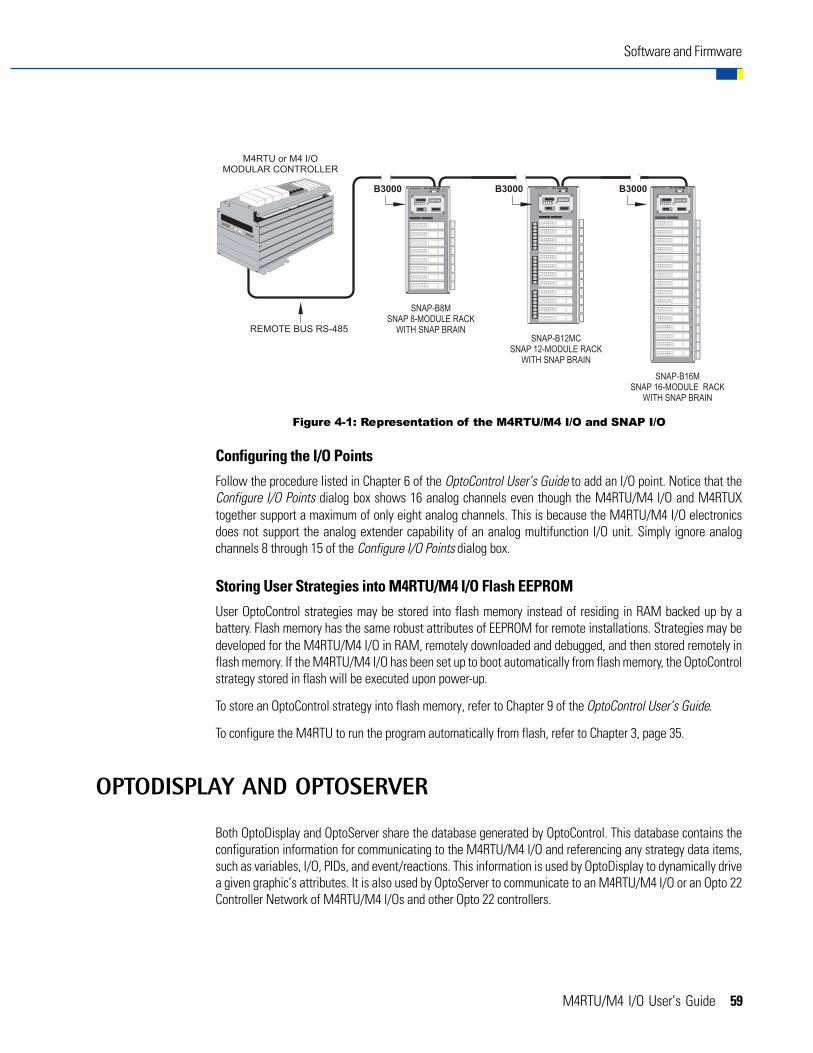
Figure 4-1: Representation of the M4RTU/M4 I/O and SNAP I/O

60 M4RTU/M4 I/O User’s Guide
To attach OptoDisplay or OptoServer to an M4RTU/M4 I/O (or to an Opto 22 Controller Network containingM4RTU/M4 I/Os), follow the standard procedures outlined in the OptoDisplay and OptoServer online help oruser’s guides for adding controllers. In short, you will be telling OptoDisplay and OptoServer which OptoControldatabase to open to access the communication information and strategy data items.
For more details regarding OptoDisplay and OptoServer, refer to the OptoDisplay User’s Guide and OptoServerUser’s Guide.
UPDATING THE M4RTU/M4 I/O FIRMWARE
The M4RTU/M4 I/O consists of two processors, each running a unique real-time, event-driven operating system.The main processor contains the firmware, which executes the control strategy generated by OptoControl. TheI/O processor contains the I/O firmware, which performs all of the various local I/O unit real-time tasks, such ascounting, PIDs, and event/reactions. Opto 22 continues to improve the firmware by adding functionality andenhancing features.
The M4RTU/M4 I/O comes preloaded with both the current Opto 22 firmware and I/O firmware. The M4RTU/M4 I/O also comes with two disks containing the current firmware files for both Cyrano and OptoControl. Thelatest firmware files are also available on Opto 22’s web site. Refer to Appendix G for details.
Each processor has a boot loader stored into a nondestructive part of its flash memory. This boot loader enablesa user to update the firmware as Opto 22 makes new firmware files available. The firmware can be updatedeither locally or remotely. This enables a user to update existing firmware, change a control strategy to takeadvantage of a new firmware feature, and download and debug the new strategy without having to venture outto an RTU site.
If you are using OptoControl, use the OptoTerm utility, included with this controller on the OptoUtilities disks, toupdate the firmware. This utility can update either the main processor firmware (flash file) or the I/O processorfirmware (I/O flash file). For details on using OptoTerm, consult online help or Chapter 12 in the OptoControlUser’s Guide.
If you are using Cyrano, use the Flash200 program on the disk packaged with this controller to update thefirmware. For details on using Flash200, consult online help.
The boot loader for the main processor currently supports COM0, COM1, ARCNET (coaxial), and Ethernet asprimary host ports for firmware updating. As new communication expansion daughter cards become availablefrom Opto 22, new flash chips with enhanced boot loaders will be developed to support them. The new flashchips will need to be installed after removing the current flash chips located on the processor board of the baseunit. Refer to Appendix E for details on this procedure.
Software and Firmware
M4RTU/M4 I/O User’s Guide 61
FIELD WIRING
OVERVIEW
This chapter provides detailed information on digital and analog field wiring for the M4RTU/M4 I/O and M4RTUX.It includes examples of how to wire all currently-available G4 digital and analog I/O modules. (If a particularmodule is not represented, please contact Opto 22 Product Support. See Appendix G for details.)
The M4RTU/M4 I/O and M4RTUX, shown in Figures 5-1 and 5-2 on the following pages, use pluggable screw-style terminal blocks for field wiring. This type of terminal block provides users with the advantages of both aterminal block and a connector. Terminal blocks furnish a robust individual wire attachment, while connectorsenable quick multi-wire disconnection. Hence, the pluggable screw-style terminal blocks provide easy installationof field wiring and easy removal of the M4RTU/M4 I/O and M4RTUX should the need arise.
A bused four-position pluggable terminal block is provided on both the M4RTU/M4 I/O and M4RTUX. Thisbused terminal block is located between the two field wire terminal blocks and can be used to bus user poweror commons. It is not connected to any power source or ground plane on the M4RTU/M4 I/O or M4RTUX.
The terminal blocks for each unit reside under a cover, preventing removal without the use of a tool. Whenattaching field wiring, make sure that the M4RTU/M4 I/O is off and that field wiring is not powered, especiallyin hazardous environments. Field wiring should be properly prepared for terminal block installation, it should beaccurately labeled, and it should be neatly dressed. Allow for adequate service loops in all field, power, andcommunication wiring.
If you will be connecting the M4RTU/M4 I/O to additional I/O units via the RS-485 serial link (remote), refer tothe Mistic 200 Systems Installation Guide and the Mistic 200 Family Data Book.
CHAPTER 5

62 M4RTU/M4 I/O User’s Guide
FIELD WIRING
Figure 5-1: Locations of Terminals on M4RTU/M4 I/O ShowingLogical Representation of Modules
Figure 5-2: Locations of Terminals on M4RTUX ShowingLogical Representation of Modules
M4RTU/M4 I/O User’s Guide 63
FIELD WIRING
.
FIELD WIRING TERMINALS
The M4RTU/M4 I/O and M4RTUX field wiring terminals are located at the top of each unit, next to theircorresponding digital and analog channel locations. Together, the M4RTU/M4 I/O and M4RTUX represent a fullcomplement of 16 digital and 8 analog channels, equivalent to the number of channels on a standard set of onedigital and one analog brick. (Although the M4RTU/M4 I/O electronics can support a full complement of digitaland analog channels, the unit does not have enough space to support these channels, hence the need for theM4RTUX I/O Extender.)
Note that although the I/O channels on the M4RTU/M4 I/O and the M4RTUX are labeled identically, thesechannels actually represent different modules logically. Hence, on the M4RTU/M4 I/O, the digital channelslabeled 0–7 and the analog channels labeled 0–3 correspond correctly to digital modules 0–7 and analogmodules 0–3, while on the M4RTUX, the channels with the same labels correspond logically to digital modules8–15 and analog modules 4–7.
Each digital channel has two terminals and each analog channel has four terminals. As with the I/O channelsthemselves, the terminals corresponding to these channels are also labeled identically on the M4RTU/M4 I/Oand M4RTUX, even though they represent different terminal connections. Hence, on the M4RTU/M4 I/O, theterminals labeled 1–16 correspond correctly to terminal connections 1–16, while on the M4RTUX, these terminalscorrespond logically to terminal connections 17–32.
Figures 5-1 and Figure 5-2 show the location of the digital and analog channels, as well as their correspondingterminals for both the M4RTU/M4 I/O and M4RTUX. See also Appendix F for field wiring worksheets.For additional wiring and module specification information, refer to the Mistic 200 Systems Installation Guideand the Mistic 200 Family Data Book.
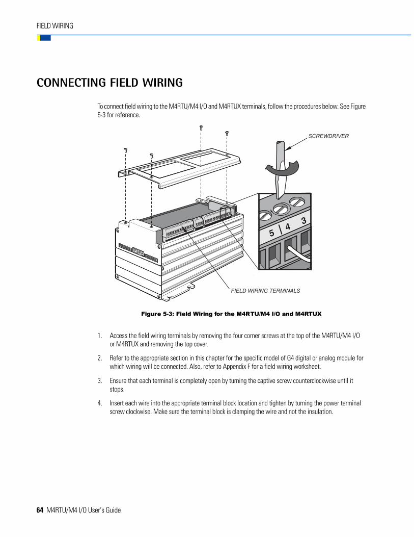
64 M4RTU/M4 I/O User’s Guide
FIELD WIRING
CONNECTING FIELD WIRING
To connect field wiring to the M4RTU/M4 I/O and M4RTUX terminals, follow the procedures below. See Figure5-3 for reference.
1. Access the field wiring terminals by removing the four corner screws at the top of the M4RTU/M4 I/Oor M4RTUX and removing the top cover.
2. Refer to the appropriate section in this chapter for the specific model of G4 digital or analog module forwhich wiring will be connected. Also, refer to Appendix F for a field wiring worksheet.
3. Ensure that each terminal is completely open by turning the captive screw counterclockwise until itstops.
4. Insert each wire into the appropriate terminal block location and tighten by turning the power terminalscrew clockwise. Make sure the terminal block is clamping the wire and not the insulation.
Figure 5-3: Field Wiring for the M4RTU/M4 I/O and M4RTUX
M4RTU/M4 I/O User’s Guide 65
WIRING DIGITAL MODULES
Each digital I/O channel has two terminals corresponding to each installed digital module. Terminals 1 and 2correspond to a module in channel 0, terminals 3 and 4 correspond to a module in channel 1, and so on. Forpolarized modules, the positive connection goes to the first terminal of the pair and the negative connectiongoes to the second. This wiring scheme is identical for the M4RTUX, starting with channel 8.
Input ModulesUse Figure 5-4 on the following page to wire the digital DC and AC input modules listed in Table 5-1. Thediagram shows a DC input module wired to channel 0 and an AC input module wired to channel 1 on theM4RTU/M4 I/O.
For the digital input modules listed in Table 5-1, the input device may be wired to either terminal. The polarityof the power does not matter except for the G4IDC5K and G4IDC5D.
Table 5-1: DC and AC Input Modules
DC InputModules
AC InputModules
G4IDC5 G4IAC5
G4IDC5K G4IAC5A
G4IDC5D G4IAC5MA
G4IDC5B ------
G4IDC5G ------
G4IDC5MA ------
Output ModulesUse Figure 5-4 to wire the digital DC and AC output modules listed in Table 5-2. The diagram shows a DC outputmodule wired to channel 6 and an AC output module wired to channel 7 on the M4RTU/M4 I/O.
For the digital output modules listed in Table 5-2, the load may be wired to either line.
Table 5-2: DC and AC Output Modules
DC OutputModules
AC OutputModules
G4ODC5 G4OAC5
G4ODC5A G4OAC5A
G4ODC5MA G4OAC5A5
G4ODC5R G4OAC5MA
G4ODC5R5 G4OAC5AMA
FIELD WIRING

66 M4RTU/M4 I/O User’s Guide
For DC output modules used with inductive loads, add a commutating diode (typically a 1N4005) to the circuitas shown on the channel 6 connection to the M4RTUX.
FIELD WIRING
Figure 5-4: Wiring for DC and AC Input/Output Modules

M4RTU/M4 I/O User’s Guide 67
Quadrature Input ModuleUse Figure 5-5 to wire the digital quadrature input module (model G4IDC5Q). The example shows the moduleconnected to channels 8 and 9 on the M4RTUX.
Note: This module requires two digital channels.
FIELD WIRING
Figure 5-5: Wiring for Digital Quadrature Input Modules
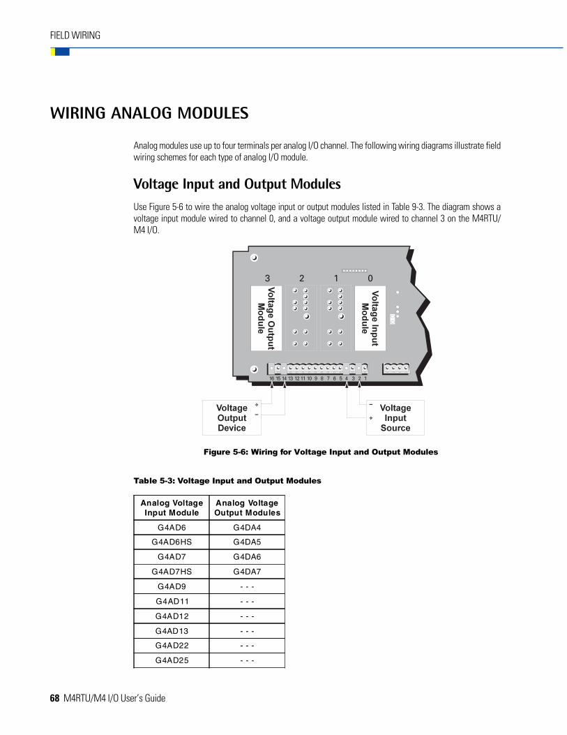
68 M4RTU/M4 I/O User’s Guide
FIELD WIRING
WIRING ANALOG MODULES
Analog modules use up to four terminals per analog I/O channel. The following wiring diagrams illustrate fieldwiring schemes for each type of analog I/O module.
Voltage Input and Output ModulesUse Figure 5-6 to wire the analog voltage input or output modules listed in Table 9-3. The diagram shows avoltage input module wired to channel 0, and a voltage output module wired to channel 3 on the M4RTU/M4 I/O.
Table 5-3: Voltage Input and Output Modules
Analog VoltageInput Module
Analog VoltageOutput Modules
G4AD6 G4DA4
G4AD6HS G4DA5
G4AD7 G4DA6
G4AD7HS G4DA7
G4AD9 - - -
G4AD11 - - -
G4AD12 - - -
G4AD13 - - -
G4AD22 - - -
G4AD25 - - -
Figure 5-6: Wiring for Voltage Input and Output Modules
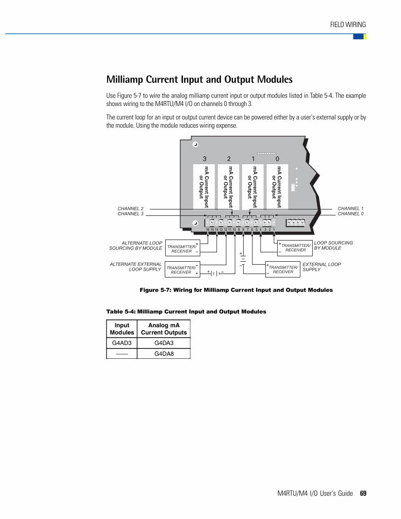
M4RTU/M4 I/O User’s Guide 69
FIELD WIRING
Milliamp Current Input and Output ModulesUse Figure 5-7 to wire the analog milliamp current input or output modules listed in Table 5-4. The exampleshows wiring to the M4RTU/M4 I/O on channels 0 through 3.
The current loop for an input or output current device can be powered either by a user’s external supply or bythe module. Using the module reduces wiring expense.
Table 5-4: Milliamp Current Input and Output Modules
InputModules
Analog mACurrent Outputs
G4AD3 G4DA3
------ G4DA8
Figure 5-7: Wiring for Milliamp Current Input and Output Modules
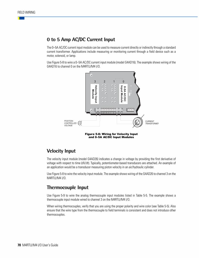
70 M4RTU/M4 I/O User’s Guide
0 to 5 Amp AC/DC Current InputThe 0–5A AC/DC current input module can be used to measure current directly or indirectly through a standardcurrent transformer. Applications include measuring or monitoring current through a field device such as amotor, solenoid, or lamp.
Use Figure 5-8 to wire a 0–5A AC/DC current input module (model G4AD16). The example shows wiring of theG4AD16 to channel 0 on the M4RTU/M4 I/O.
Velocity InputThe velocity input module (model G4AD26) indicates a change in voltage by providing the first derivative ofvoltage with respect to time (dV/dt). Typically, potentiometer-based transducers are attached. An example ofan application would be a transducer measuring piston velocity in an air/hydraulic cylinder.
Use Figure 5-8 to wire the velocity input module. The example shows wiring of the G4AD26 to channel 3 on theM4RTU/M4 I/O.
Thermocouple InputUse Figure 5-9 to wire the analog thermocouple input modules listed in Table 5-5. The example shows athermocouple input module wired to channel 3 on the M4RTU/M4 I/O.
When wiring thermocouples, verify that you are using the proper polarity and wire color (see Table 5-5). Alsoensure that the wire type from the thermocouple to field terminals is consistent and does not introduce otherthermocouples.
FIELD WIRING
Figure 5-8: Wiring for Velocity Inputand 0–5A AC/DC Input Modules
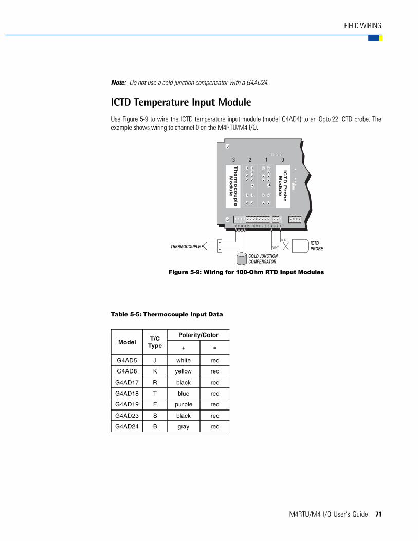
M4RTU/M4 I/O User’s Guide 71
FIELD WIRING
Note: Do not use a cold junction compensator with a G4AD24.
ICTD Temperature Input ModuleUse Figure 5-9 to wire the ICTD temperature input module (model G4AD4) to an Opto 22 ICTD probe. Theexample shows wiring to channel 0 on the M4RTU/M4 I/O.
Table 5-5: Thermocouple Input Data
ModelT/C
Type
Polarity/Color
+ -G4AD5 J white red
G4AD8 K yellow red
G4AD17 R black red
G4AD18 T blue red
G4AD19 E purple red
G4AD23 S black red
G4AD24 B gray red
Figure 5-9: Wiring for 100-Ohm RTD Input Modules
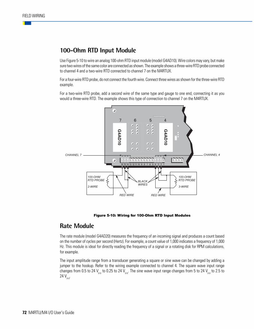
72 M4RTU/M4 I/O User’s Guide
FIELD WIRING
100-Ohm RTD Input ModuleUse Figure 5-10 to wire an analog 100-ohm RTD input module (model G4AD10). Wire colors may vary, but makesure two wires of the same color are connected as shown. The example shows a three-wire RTD probe connectedto channel 4 and a two-wire RTD connected to channel 7 on the M4RTUX.
For a four-wire RTD probe, do not connect the fourth wire. Connect three wires as shown for the three-wire RTDexample.
For a two-wire RTD probe, add a second wire of the same type and gauge to one end, connecting it as youwould a three-wire RTD. The example shows this type of connection to channel 7 on the M4RTUX.
Rate ModuleThe rate module (model G4AD20) measures the frequency of an incoming signal and produces a count basedon the number of cycles per second (Hertz). For example, a count value of 1,000 indicates a frequency of 1,000Hz. This module is ideal for directly reading the frequency of a signal or a rotating disk for RPM calculations,for example.
The input amplitude range from a transducer generating a square or sine wave can be changed by adding ajumper to the hookup. Refer to the wiring example connected to channel 4. The square wave input rangechanges from 0.5 to 24 Vp-p to 0.25 to 24 Vp-p. The sine wave input range changes from 5 to 24 Vp-p to 2.5 to24 Vp-p.
Figure 5-10: Wiring for 100-Ohm RTD Input Modules
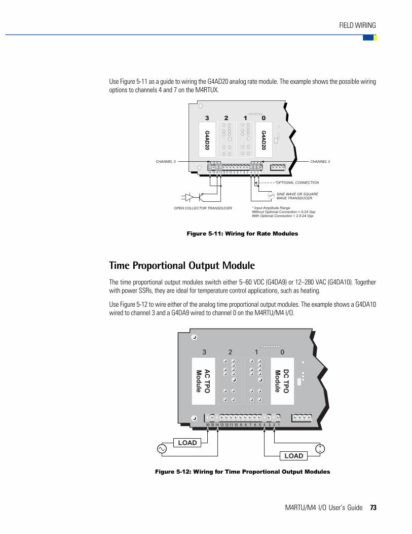
M4RTU/M4 I/O User’s Guide 73
Use Figure 5-11 as a guide to wiring the G4AD20 analog rate module. The example shows the possible wiringoptions to channels 4 and 7 on the M4RTUX.
Time Proportional Output ModuleThe time proportional output modules switch either 5–60 VDC (G4DA9) or 12–280 VAC (G4DA10). Togetherwith power SSRs, they are ideal for temperature control applications, such as heating.
Use Figure 5-12 to wire either of the analog time proportional output modules. The example shows a G4DA10wired to channel 3 and a G4DA9 wired to channel 0 on the M4RTU/M4 I/O.
FIELD WIRING
Figure 5-11: Wiring for Rate Modules
Figure 5-12: Wiring for Time Proportional Output Modules

74 M4RTU/M4 I/O User’s Guide
FIELD WIRING
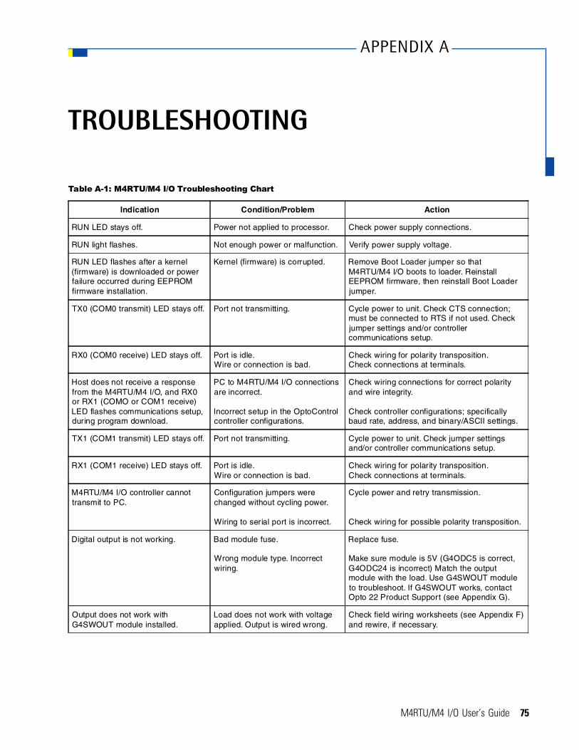
M4RTU/M4 I/O User’s Guide 75
TROUBLESHOOTING
Table A-1: M4RTU/M4 I/O Troubleshooting Chart
Indication Condition/Problem Action
RUN LED stays off. Power not applied to processor. Check power supply connections.
RUN light flashes. Not enough power or malfunction. Verify power supply voltage.
RUN LED flashes after a kernel(firmware) is downloaded or powerfailure occurred during EEPROMfirmware installation.
Kernel (firmware) is corrupted. Remove Boot Loader jumper so thatM4RTU/M4 I/O boots to loader. ReinstallEEPROM firmware, then reinstall Boot Loaderjumper.
TX0 (COM0 transmit) LED stays off. Port not transmitting. Cycle power to unit. Check CTS connection;must be connected to RTS if not used. Checkjumper settings and/or controllercommunications setup.
RX0 (COM0 receive) LED stays off. Port is idle.Wire or connection is bad.
Check wiring for polarity transposition. Check connections at terminals.
Host does not receive a responsefrom the M4RTU/M4 I/O, and RX0or RX1 (COMO or COM1 receive)LED flashes communications setup,during program download.
PC to M4RTU/M4 I/O connectionsare incorrect.
Incorrect setup in the OptoControlcontroller configurations.
Check wiring connections for correct polarityand wire integrity.
Check controller configurations; specificallybaud rate, address, and binary/ASCII settings.
TX1 (COM1 transmit) LED stays off. Port not transmitting. Cycle power to unit. Check jumper settingsand/or controller communications setup.
RX1 (COM1 receive) LED stays off. Port is idle.Wire or connection is bad.
Check wiring for polarity transposition.Check connections at terminals.
M4RTU/M4 I/O controller cannottransmit to PC.
Configuration jumpers werechanged without cycling power.
Wiring to serial port is incorrect.
Cycle power and retry transmission.
Check wiring for possible polarity transposition.
Digital output is not working. Bad module fuse.
Wrong module type. Incorrectwiring.
Replace fuse.
Make sure module is 5V (G4ODC5 is correct,G4ODC24 is incorrect) Match the outputmodule with the load. Use G4SWOUT moduleto troubleshoot. If G4SWOUT works, contactOpto 22 Product Support (see Appendix G).
Output does not work withG4SWOUT module installed.
Load does not work with voltageapplied. Output is wired wrong.
Check field wiring worksheets (see Appendix F)and rewire, if necessary.
APPENDIX A

76 M4RTU/M4 I/O User’s Guide
TROUBLESHOOTING
Table A-1: M4RTU/M4 I/O Troubleshooting Chart (continued)
Indication Condition/Problem Action
Digital input is not working. Input device is not workingproperly.
Wrong module type.
Voltage on input is notcompatible with module voltagerange.
I/O or processor board is bad.
Check input device wiring and power source. Rewire,replace, or fix power source as needed.
Make sure module is 5V (for example, [G4IDC5 iscorrect, G4IDC24] is incorrect).
Change voltage to match module or module to matchvoltage.
Use G4SWIN module and OptoControl or G4TEST tosend commands to the M4RTU/M4 I/O to verify that theprocessor board and I/O board are working properly.
Digital input test withG4SWIN module installed.
I/O or processor board is bad. Contact Opto 22 Product Support (see Appendix G).
Analog output is not working. Output is wired incorrectly.Device is not properly matchedto module type.
I/O or processor board is bad.
Check wiring to output device. Test module using meterand test software (OptoControl or G4TEST). Changevoltage to match module or module to match voltage.
Contact Opto 22 if meter reading does not change withvalue change in test software.
Analog input is not working. Voltage output device is wiredincorrectly.
Thermocouple has a break.
RTD has open or incorrectwiring.
I/O or processor board is bad.
Check device and wiring. Connect voltage source orcurrent source (depending on input type) and use testsoftware to determine if input is functioning.
For a thermocouple, check for continuity across testpoints next to module.
For an RTD input, check resistance across test pointsnext to module.
Contact Opto 22 Product Support if any of the followingoccurs:- If value in test software does not change with inputwhen testing input voltage or current with test software.- If thermocouple has continuity across test points.- If resistance across test points is about 100 ohms forRTD input.

M4RTU/M4 I/O User’s Guide 77
CABLE AND CONNECTORSPECIFICATIONS
SERIAL COMMUNICATION CABLES
The following cables are recommended for both RS-232 and RS-485/422 serial communications. Although youmay elect to use other cables, keep in mind that low capacitance (less than 15 pF/ft.) is important for high-speed digital communication links. The cables listed below are all 24-gauge, 7x32 stranded, with 100-ohmnominal impedance and a capacitance of 12.5 pF/ft.
Select from the following two-, three-, and four-pair cables, depending on your application needs. All will yieldsatisfactory results. It is recommended that you choose a cable with one more pair than your applicationrequires. Use one of the extra wires, rather than the shield, for the common.
Two-Pair:
• Belden P/N 8102 (with overall shield)
• Belden P/N 9729 (individually shielded)
• Belden P/N 8162 (individually shielded with overall shield)
• Manhattan P/N M3475 (individually shielded with overall shield)
• Manhattan P/N M39249 (individually shielded with overall shield)
Three-Pair:
• Belden P/N 8103 (with overall shield)
• Belden P/N 9730 (individually shielded)
• Belden P/N 8163 (individually shielded with overall shield)
• Manhattan P/N M3476 (individually shielded with overall shield)
• Manhattan P/N M39250 (individually shielded with overall shield)
Four-Pair:
• Belden P/N 8104 (with overall shield)
• Belden P/N 9728 (individually shielded)
• Belden P/N 8164 (individually shielded with overall shield)
• Manhattan P/N M3477 (individually shielded with overall shield)
• Manhattan P/N M39251 (individually shielded with overall shield)
APPENDIX B

78 M4RTU/M4 I/O User’s Guide
CABLE AND CONNECTOR SPECIFICATIONS
M4RTU/M4 I/O CONNECTORS
The following connectors are included with the M4RTU/M4 I/O:
Green Pluggable 7-Position Terminal Mini-Plug
• Used for RS-232 and RS-485/422 connections from the M4RTU/M4 I/O (COM0 and COM1) and theM4SSER (COM2 and COM3)
• Manufactured by Phoenix Contact (P/N MC1, 5/7-ST-3, 81)
Green Pluggable 3-Position Terminal Plug
• Used for M4RTU/M4 I/O power connection
• Manufactured by Phoenix Contact (P/N MSTB 2, 5/3-STF-5, 08)
Green Pluggable 16-Position I/O Connector
• Used for wiring from the M4RTU/M4 I/O and M4RTUX to field application hardware
• Manufactured by Phoenix Contact (P/N MVSTBR 2, 5/16-ST-5, 08)

M4RTU/M4 I/O User’s Guide 79
PRODUCT SPECIFICATIONS
Table C-1: M4RTU/M4 I/O Base Unit Hardware Specifications
Item Specification
CPU32-bit Motorola 68020 processor16-bit 80C196 I/O processorIEEE floating-point math
CPU clock frequency 16.67 MHz
Memory: RAM Flash EEPROM on controller Flash EEPROM on brain board
1 MB with battery backup (user programs & data)256 KB - 1 MB (firmware and user programs)128 KB (I/O firmware)
RAM/clock battery 3.6-volt lithium, non-rechargeable
I/O: Base unit Extender unit Expansion
8 digital, 4 analog, multifunctionAdds 8 digital, 4 analog, multifunctionVia RS-485 ports, using Opto 22 I/O
Communication: Base unit
Expansion Modem support
1 RS-232 and 1 RS-485/422 portVia daughter cards: configurable serial ports and ARCNETDirect, lease, and radio
Real-time clock Clock/calendar, Epson 62421A with battery backup
Power requirements5 VDC at 3.5 A (maximum)24 VDC at 300 mA (maximum)
Typical operating temperature -20° C to 70° C
Storage temperature -40° C to 85° C
Humidity 5% to 95% relative humidity
SoftwareFactoryFloor (OptoControl, OptoDisplay, and Optoserver)Classic Software (Cyrano, Mistic MMI, and MDS)
System monitors: Host communications Watchdog timers RAM battery backup low Operating temperature
Detect communication errors from processor, I/O, etc.Detect main power supply operationDetects program corruption (checksum RAM test)Detects temperature
APPENDIX C

80 M4RTU/M4 I/O User’s Guide
PRODUCT SPECIFICATIONS

M4RTU/M4 I/O User’s Guide 81
ADDRESS JUMPER CONFIGURATION
The M4RTU/M4 I/O includes eight address jumpers, as described in Chapter 3. To set the jumpers based on apredetermined address, refer to the chart below.
For details on accessing and setting these jumpers, see Chapter 3.
Figure D-1: M4RTU/M4 I/O Address Jumper Configurations
APPENDIX D

82 M4RTU/M4 I/O User’s Guide
ADDRESS JUMPER CONFIGURATION
M4RTU/M4 I/O User’s Guide 83
UPGRADING RAMAND FLASH EEPROM
OVERVIEW
If the M4RTU/M4 I/O does not have a “1 MB RAM Installed” sticker, you can expand the M4RTU/M4 I/O RAMfrom 256 KB to 1 MB. You can also expand the flash EEPROM from 256 KB to 1 MB. To do such an upgrade,it is necessary to remove and disassemble the M4RTU/M4 I/O base unit to access the processor board wherethe RAM and flash EEPROM chips are located. You can also use this process to upgrade the processor boardwith flash chips containing new enhanced boot loaders supporting new primary host communication hardware(e.g., fiber or Ethernet).
To disassemble the M4RTU/M4 I/O, follow these instructions:
1. Turn off the power to the M4RTU/M4 I/O.
2. Disconnect the incoming electrical power from the power supply.
3. Remove the four screws located on the top cover of the unit. Take off the top cover. Disconnect the fieldwiring plug connectors.
4. Remove any communication port connectors and/or M4RTUXCAB cables.
* Do not change this jumper.
Figure E-1: Locations of Jumpers and Chips on the M4RTU/M4 I/O
APPENDIX E

84 M4RTU/M4 I/O User’s Guide
UPGRADING RAM AND FLASH EEPROM
5. Remove the unit from its mounted position by removing the four user-supplied screw assemblies fromthe mounting flanges.
6. Remove the top end cap on the power supply end of the M4RTU/M4 I/O base unit by removing the twoscrews at the top corners of the end cap.
7. Grasp the edge of the I/O and processor boards and pull firmly until the two boards disengage from theM4BUS and slide completely out of the M4RTU/M4 I/O enclosure.
8. Gently pull the I/O board up and away from the processor board to separate the two boards. (The I/Oboard is parallel and on top of the processor board.) Carefully set the I/O board aside.
9. Using a chip puller, carefully remove the U13 and U15 chips for a RAM upgrade or the U12 and U14chips for a flash EEPROM upgrade.
10. When upgrading flash EEPROM, install each chip in its correct position (U12 or U14). Each will bemarked with its position. (See Figure E-1.)
When upgrading RAM, you may install either chip in either position (U13 or U15).
Note: Ensure that the chips are correctly oriented; the notch on the chip should line up with the notch on thesilk screen on the board.
11. After correctly positioning each chip, make sure it is securely seated; however, do not attempt to forceor bend the chip in place!
12. Once all chips are physically installed, set the jumpers located on the processor board to correspond tothe new RAM or flash EEPROM size. See “Setting Configuration Jumpers and Switches” in Chapter 3and refer to Table 3-2 for proper jumper settings.
13. To put the unit back together, undo steps 1–8 in reverse order.

M4RTU/M4 I/O User’s Guide 85
UPGRADING RAM AND FLASH EEPROM
Use Table E-1 to select RAM expansion options for your controller.
Table E-1: RAM Expansion Options
RAM
Size
G4LC32 G4LC32SX G4LC32ISA M4RTU/M4IO/M4
Original1 New1 Original2 New2 ____________ Original3 New3
256K N/A N/ABase
ConfigurationBase
ConfigurationBase
ConfigurationBase
configurationN/A
512KBase
ConfigurationBase
ConfigurationN/A N/A
G4RAM1MN/A N/A
1M G4LC32RAMEX5MBuy 4
G4RAM1MN/A
Buy2G4RAM4M G4RAM4M G4RAM4M
BaseConfiguration
2M N/ABuy 4
G4RAM4MN/A N/A
Buy 4G4RAM 4M
N/A N/A
4M G4LC32RAMEX4MG4RAM4M
N/A N/A N/A N/A N/A
Use Table E-2 to select EPROM expansion options for your controller.
Table E-2: EPROM Expansion Options
SizeG4LC32 G4LC32SX G4LC32ISA M4RTU/
M4IO/M4
Original New (Flash) Original New (Flash) Flash Flash
128K Base Configuration N/ABase
Configuration N/A N/A N/A
256K Buy 4 27C512-1204 N/A N/A BaseConfiguration
BaseConfiguration
BaseConfiguration
512K Buy 4 27C010-1204 BaseConfiguration N/A N/A N/A N/A
1M Buy 4 27C020-1204 G4LC32F1M N/A G4LC32SXF1M G4LC32ISAF1M M4RTUF1M
Notes:
1 = Chips from Intel (N/A from Opto 22). Older chips had a 256K base configuration.
2 = See attached to determine if you have a new style G4LC32/G4LC32SX or old style G4LC32/G4LC32SX.
3 = New controllers are marked with a “1MB RAM installed” sticker.

86 M4RTU/M4 I/O User’s Guide
UPGRADING RAM AND FLASH EEPROM

M4RTU/M4 I/O User’s Guide 87
WORKSHEETS
The following worksheets can be used to plan I/O module installation for the M4RTU/M4 I/O base unit andM4RTUX I/O extender unit.
Worksheet InstructionsFill in the digital or analog I/O type in the box to the right of each I/O channel shown on the worksheet.The following is an example of a completed worksheet:
* When configuring digital or analog I/O for the M4RTU/M4 I/O base unit using OptoControl, use theseaddresses and make sure the PORT type is LOCAL. See Chapter 4 (Software and Firmware) for moreinformation.
Figure F-1: Sample I/O Module Worksheet
APPENDIX F
88 M4RTU/M4 I/O User’s Guide
WORKSHEETS
* When configuring digital or analog I/O for the M4RTU/M4 I/O base unit using OptoControl, use theseaddresses and make sure the PORT type is LOCAL. See Chapter 4 (Software and Firmware) for moreinformation.
Figure F-2: M4RTU/M4 I/O Base Unit–I/O Module Worksheet
Updated: 7/9/99

M4RTU/M4 I/O User’s Guide 89
WORKSHEETS
Figure F-3: M4RTUX I/O Extender–I/O Module Worksheet

90 M4RTU/M4 I/O User’s Guide
WORKSHEETS
FIELD WIRING WORKSHEET
The following worksheet can be used to plan and implement field wiring installation for the M4RTU/M4 I/Obase unit and M4RTUX I/O Extender.
Worksheet InstructionsFill in the wire name boxes for each terminal. The Field Wiring Worksheet can be used by your installer duringRTU installation. If you need additional worksheets, make copies before filling this out.
Figure F-4: Field Wiring Worksheet Example 1

M4RTU/M4 I/O User’s Guide 91
WORKSHEETS
Figure F-5: Field Wiring Worksheet Example 2

92 M4RTU/M4 I/O User’s Guide
WORKSHEETS
Field Wiring Worksheet Examples
¹If the daughter card you are using does not appear above, call Opto 22 for a data sheet or contact Opto 22Product Support for wattage specifications.
²If the digital module you are using does not appear above, use the G4 Digital AC/DC Input Output modulewattage.
³If the analog module you are using does not appear above, use the G4ADX wattage.
HardwareWatts
(W)Quantity
(Q)Total
(W x Q)
M4RTU/M4 I/O Base Unit 7.5 1.0 7.5
M4RTUX I/O Extender Unit 0 0
Daughter Cards¹
M4SSER 1.6
M4SARC 1.0
M4SARCF 1.1
M4SARCFR 1.6
M4SENETC 3.1
M4SENETU 1.50
M4DUALARC 0.7
M4ENET100 4.1
Digital I/O Modules:
G4 Digital AC/DC Input/Output² 0.086
G4ODC5R, G4ODC5R5 0.10
G4IDC5Q 0.43
Analog I/O Modules:
G4ADX³ 1.6
G4AD3Sourcing:Non-Sourcing:
2.61.6
G4DA4Sourcing:Non-Sourcing:
2.21.1
G4DA3, G4DA8Sourcing:Non-Sourcing:
2.61.2
G4DA9, G4DA10 0.18
Powered RS-232 devices(e.g., barcode reader)
Total Watts (TW): _______W
Your supplied input voltage: _______V
TW/Your supplied input voltage = Input Current _______A

M4RTU/M4 I/O User’s Guide 93
WORKSHEETS
M4RTU/M4 I/O POWER CONSUMPTION WORKSHEET
Instructions1. On the previous worksheet, locate the daughter cards and digital and/or analog modules you will be
using with the M4RTU/M4 I/O. Enter a quantity for each item in the “Quantity” column. Also, fill in thequantity and wattage of any RS-232 devices on the line provided.
2 . Multiply the value in the “Watts” column by the quantity entered in the “Quantity” column and enterthe result in the “Total” column for each component used.
Example: Eight G4 digital module totals 0.688 W. Four G4ADX analog modules total 6.4 W.
3. Add the values in the “Total” column, including the value entered for the M4RTU/M4 I/O base unit,and enter the result on the “Total Watts” line.
Example: 0.688 W (digital modules) + 6.4 W (analog modules) + 7.5 W (base RTU) = 14.588 W.
4. Enter the supplied input voltage for your installation on the “Your supplied input voltage” line.
Example: 24 VDC.
5. Divide the total on the “Total Watts” line by the number entered on the “Your supplied input voltage”line to calculate your total input current requirements. Enter this number on the last line of theworksheet.
Example: 14.588 W (total watts)/24 VDC (supplied input) = 0.6 A required input current for the M4RTU/M4 I/O.

94 M4RTU/M4 I/O User’s Guide
WORKSHEETS

M4RTU/M4 I/O User’s Guide 95
PRODUCT SUPPORT
If you have any questions about this product, contact Opto 22 Product Support Monday through Friday,8 a.m. to 5 p.m. Pacific Time.
Phone: 800-TEK-OPTO (835-6786)951-695-3080
Fax: 951-695-3017
E-mail: [email protected]
Opto 22 Web site: www.opto22.com
When calling for technical support, be prepared to provide the following information about your system to theProduct Support engineer:
• Software and version being used
• Controller firmware version
• PC configuration
• A complete description of your hardware and operating systems, including:— jumper configuration— accessories installed (such as expansion daughter cards)— type of power supply— types of I/O units installed— third-party devices installed (e.g., barcode readers)
• Specific error messages seen
APPENDIX G

96 M4RTU/M4 I/O User’s Guide
PRODUCT SUPPORT

M4RTU/M4 I/O User’s Guide 97
A
addressjumpers 37, 81
analog I/O modules 10wiring 47, 68
applications 12ARCnet 11, 36, 58
expansion daughter cards 36and baud rate jumper settings 36
ASCII communication mode 36Autoboot jumper 36
B
battery 22connecting 33–50location 33
baud ratejumpers 36
binary communication mode 36boot loader 60
jumper 36bulletin board service 95
C
cable specifications 77–78client/server architecture 57communication
configurations 13configuring through OptoControl 27mode
jumper 36verifying 28
connecting field wiring 46–50, 64connecting power to the M4RTU/DAS 44–50connectors
specifications 78control program 36, 57, 60current input module 70Cyrano 60
kernel 20
D
digital I/O modules 10wiring 47, 65
E
Ethernet 11, 36, 58expansion daughter cards
and baud rate jumper settings 36expansion daughter cards 23
installation 40
F
FactoryFloor 9, 12field wiring 46–50, 61
connecting 64terminals 63worksheets 87–93
firmwareupdating 60
Flashjumpers 38
Flash EEPROM 36, 57chips, location of 83downloading strategies to 59–60upgrading 83
G
G4IOR Remote Interface 54gas/petrochemical devices 13
H
hardware specifications 79host computer
configuring communications to 27verifying communications to 28
Host Port jumpers 36
INDEX

98 M4RTU/M4 I/O User’s Guide
I
I/Oboard 45bricks
configuring through OptoControl 58–60modules
installing 45–50logical representation of, in OptoControl 63
points, configuring through OptoControl 58–60, 59–60
Remote Interface 54units
configuring through OptoControl 58–60integration with 13
ICTD temperature input module 71input modules
table of 65wiring 65
intelligent equipment devices (IEDs) 10, 13
J
jumpers 23, 34Address 37, 81Autoboot 36Baud Rate 36Boot Loader 36Communication Mode 36diagram of 23Flash 38Host Port 36RAM 38Ring Indicator 38ROM 38
K
kernel 20, 36, 60downloading to Flash memory 12
L
LED indicatorsM4RTU/DAS 56
local bus 58
M
M4BUS 9, 10, 11M4RTU/DAS
backup battery 22, 33block diagram 16, 17cable and connector specifications 77communications, configuring through OptoControl
58–60connecting field wiring to 46–50connecting power to 44diagram of terminals on 62disassembling 83exploded views 30field wiring 61, 64
worksheet 87–93firmware, updating 60hardware diagrams 17I/O board 45I/O, configuring through OptoControl 58jumpers 34–50
diagram of 23table of 35
mounting 24, 42–50operator interface 59options 11packing list 20power consumption worksheet 93power supplies 20, 21power switch, diagram of 27programming 57quick installation procedures 19serial ports 48switches 34, 39system monitors 10troubleshooting 75–76upgrading RAM and Flash EEPROM 83wiring to a host PC 49–50
M4RTUX 11, 23, 41–50connecting to the M4RTU/DAS 41–50diagram of terminals on 62field wiring 61, 64
worksheet 87–93I/O, configuring through OptoControl 58
M4RTUXCAB 11, 23connecting 41–50
INDEX

M4RTU/M4 I/O User’s Guide 99
M4SARC 36M4SARCF/M4SARCFR 36M4SENET 36M4SSER 48, 54milliamp current input/output modules 69
table of 69mistic
I/O Remote Interface block 54kernel 36
modemwiring to 52
modems 12mounting template
M4RTU/DAS 20mounting the M4RTU/DAS 24, 42–50
O
OEM applications 12OptoControl 11, 27–28, 57, 58–60
Configure Controllers dialog 37configuring communications in 58kernel 20strategies, downloading to Flash EEPROM 59–60
OptoDisplay 12, 57, 59–60OptoServer 12, 57, 59OptoTerm 60OptoUtilities 20
OptoTerm 60output modules
wiring 65
P
peer-to-peer communications 12ports. See serial portspower consumption worksheet 93power supplies 11, 20, 21
installing 31–50processor board 10product specifications 79Product Support 95
Q
quadrature input module 67quick start 19–28
R
RAM 36chips, location of 83jumpers 38upgrading 83
rate module 72remote bus 10
serial link 58remote operations
data uploading and downloading 12kernel downloading to Flash memory 12program downloading and debugging 12
remote plant management system 12Ring Indicator jumper 38ROM
jumpers 38RS-232 10, 58
cable specifications 77communications 36extra programmable input for 38pin connections 25serial port 48wiring 25wiring to a PC 50
RS-485/422 10, 54, 58cable specifications 77communications 36pin connections 49serial port 48switches 39wiring 39wiring to a PC 50
RTD input module 72
S
sample applications 12SCADA systems 10, 12serial communication cables 77–78serial port
switches 36, 39serial ports 10, 48
wiring 48–50software 11, 57–60specifications, hardware 79
INDEX

100 M4RTU/M4 I/O User’s Guide
storing user strategies in Flash EEPROM 59–60subsystem automation gear 13switches 34, 39
2-wire/4-wire 39termination 39
T
tank farm application 12Technical Support 95terminal blocks 61terminal connectors 78terminals 63
diagram 62termination
switches 39thermocouple input module 70thermocouple input modules 70
table of 71time proportional output modules 73troubleshooting 75–76two-way dial-up capability 12typical applications 12
U
upgrading RAM and Flash EEPROM 83
V
velocity input module 70voltage input/output modules 68
W
wastewater equipment 13watchdog timers 10wiring 48–50
analog modules 68digital modules 65to modem 52worksheets 87–93
worksheets, field wiring 87–93
INDEX