Embed Size (px)
DESCRIPTION
Â
Citation preview
Semester 2/2013 Group 11
Shanaaz Mutaliph640 182
Virtual Environments ENVS10008
Second Skin Profile and Section
module1IDEATION
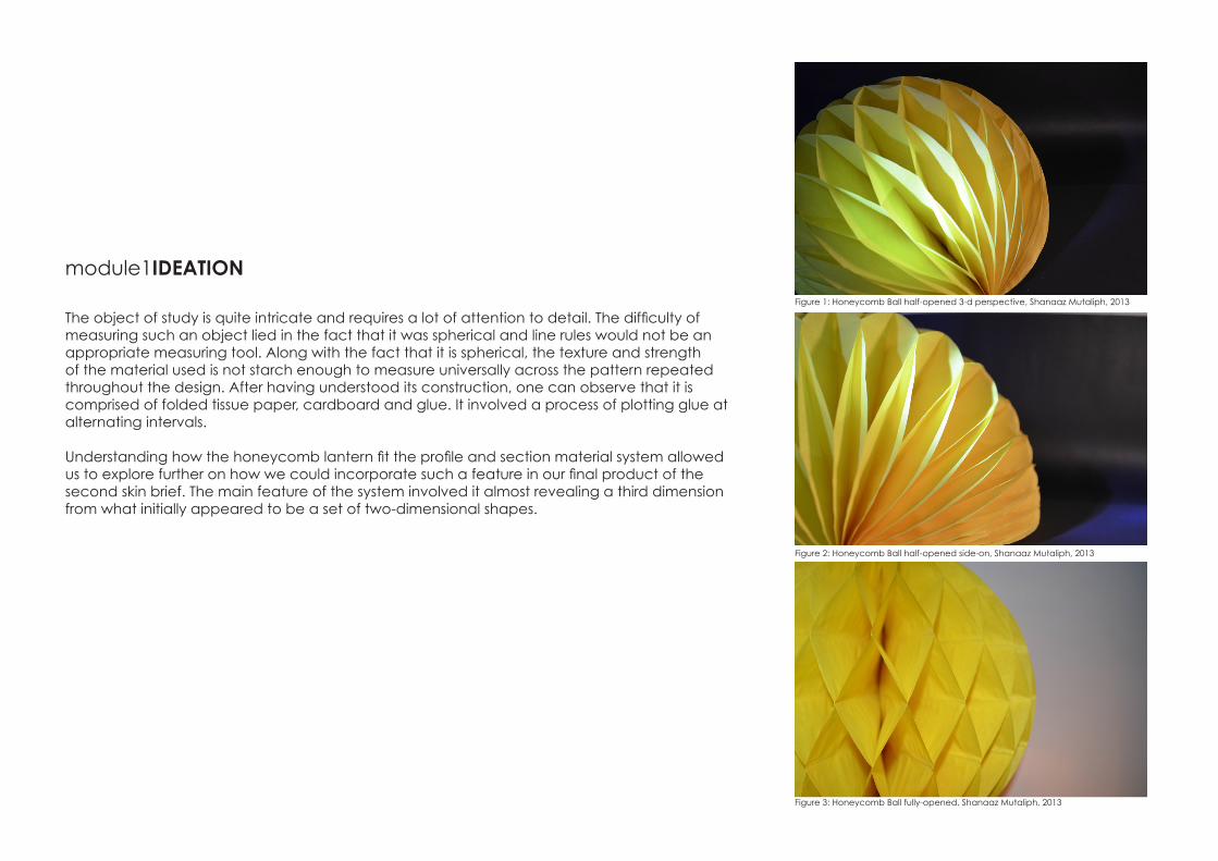
The object of study is quite intricate and requires a lot of attention to detail. The difficulty of measuring such an object lied in the fact that it was spherical and line rules would not be an appropriate measuring tool. Along with the fact that it is spherical, the texture and strength of the material used is not starch enough to measure universally across the pattern repeated throughout the design. After having understood its construction, one can observe that it is comprised of folded tissue paper, cardboard and glue. It involved a process of plotting glue at alternating intervals.
Understanding how the honeycomb lantern fit the profile and section material system allowed us to explore further on how we could incorporate such a feature in our final product of the second skin brief. The main feature of the system involved it almost revealing a third dimension from what initially appeared to be a set of two-dimensional shapes.
Figure 1: Honeycomb Ball half-opened 3-d perspective, Shanaaz Mutaliph, 2013
Figure 2: Honeycomb Ball half-opened side-on, Shanaaz Mutaliph, 2013
Figure 3: Honeycomb Ball fully-opened, Shanaaz Mutaliph, 2013
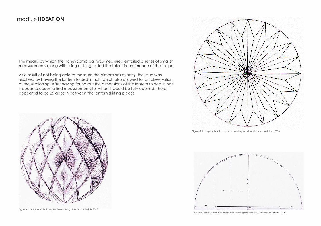
The means by which the honeycomb ball was measured entailed a series of smaller measurements along with using a string to find the total circumference of the shape.
As a result of not being able to measure the dimensions exactly, the issue was resolved by having the lantern folded in half, which also allowed for an observation of the sectioning. After having found out the dimensions of the lantern folded in half, it became easier to find measurements for when it would be fully opened. There appeared to be 25 gaps in between the lantern skirting pieces.
Figure 5: Honeycomb Ball measured drawing top view, Shanaaz Mutaliph, 2013
Figure 6: Honeycomb Ball measured drawing closed view, Shanaaz Mutaliph, 2013Figure 4: Honeycomb Ball perspective drawing, Shanaaz Mutaliph, 2013
module1IDEATION
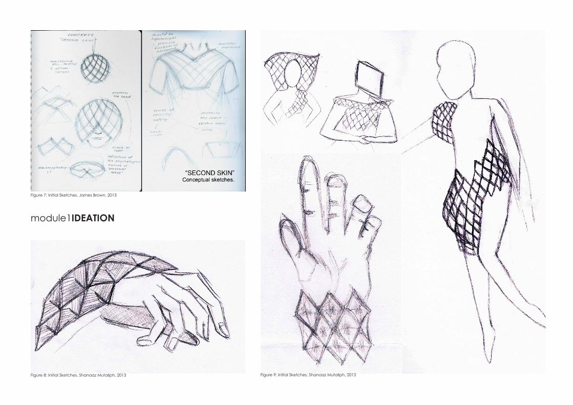
Figure 7: Initial Sketches, James Brown, 2013
Figure 8: Initial Sketches, Shanaaz Mutaliph, 2013 Figure 9: Initial Sketches, Shanaaz Mutaliph, 2013
module1IDEATION
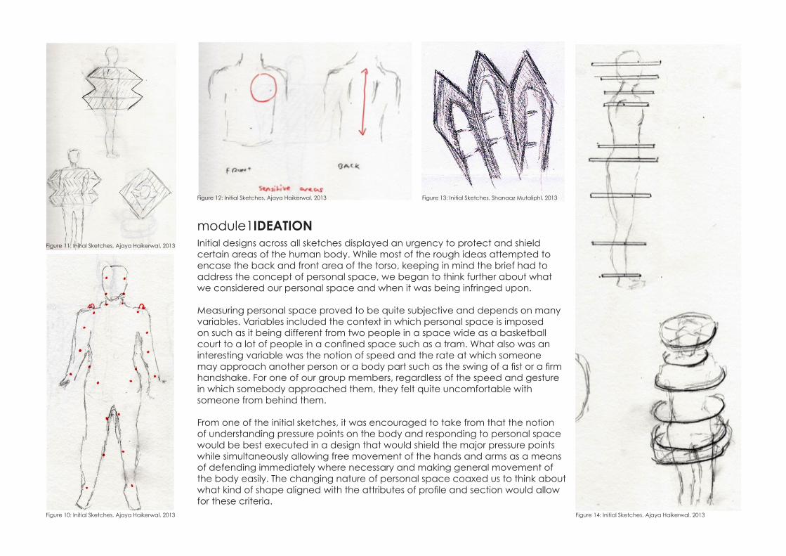
Initial designs across all sketches displayed an urgency to protect and shield certain areas of the human body. While most of the rough ideas attempted to encase the back and front area of the torso, keeping in mind the brief had to address the concept of personal space, we began to think further about what we considered our personal space and when it was being infringed upon.
Measuring personal space proved to be quite subjective and depends on many variables. Variables included the context in which personal space is imposed on such as it being different from two people in a space wide as a basketball court to a lot of people in a confined space such as a tram. What also was an interesting variable was the notion of speed and the rate at which someone may approach another person or a body part such as the swing of a fist or a firm handshake. For one of our group members, regardless of the speed and gesture in which somebody approached them, they felt quite uncomfortable with someone from behind them.
From one of the initial sketches, it was encouraged to take from that the notion of understanding pressure points on the body and responding to personal space would be best executed in a design that would shield the major pressure points while simultaneously allowing free movement of the hands and arms as a means of defending immediately where necessary and making general movement of the body easily. The changing nature of personal space coaxed us to think about what kind of shape aligned with the attributes of profile and section would allow for these criteria.
Figure 10: Initial Sketches, Ajaya Haikerwal, 2013 Figure 14: Initial Sketches, Ajaya Haikerwal, 2013
Figure 11: Initial Sketches, Ajaya Haikerwal, 2013
Figure 12: Initial Sketches, Ajaya Haikerwal, 2013 Figure 13: Initial Sketches, Shanaaz Mutaliphl, 2013
module1IDEATION
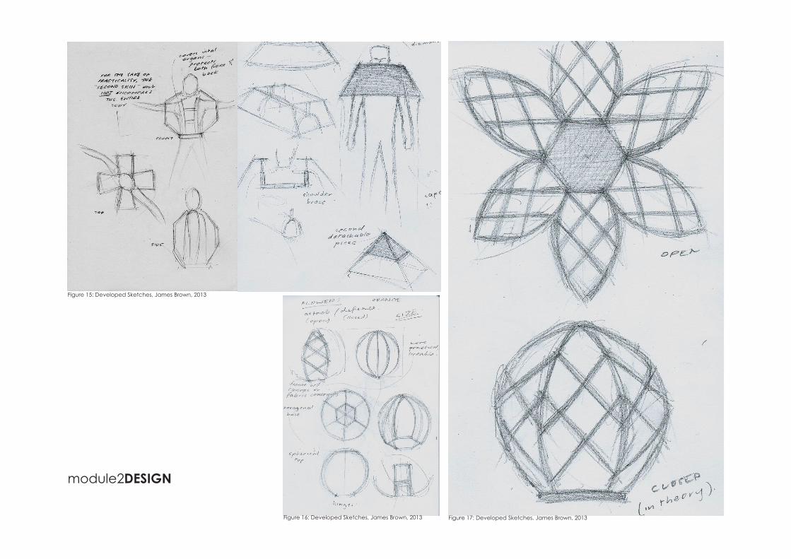
Figure 15: Developed Sketches, James Brown, 2013
Figure 16: Developed Sketches, James Brown, 2013 Figure 17: Developed Sketches, James Brown, 2013
module2DESIGN
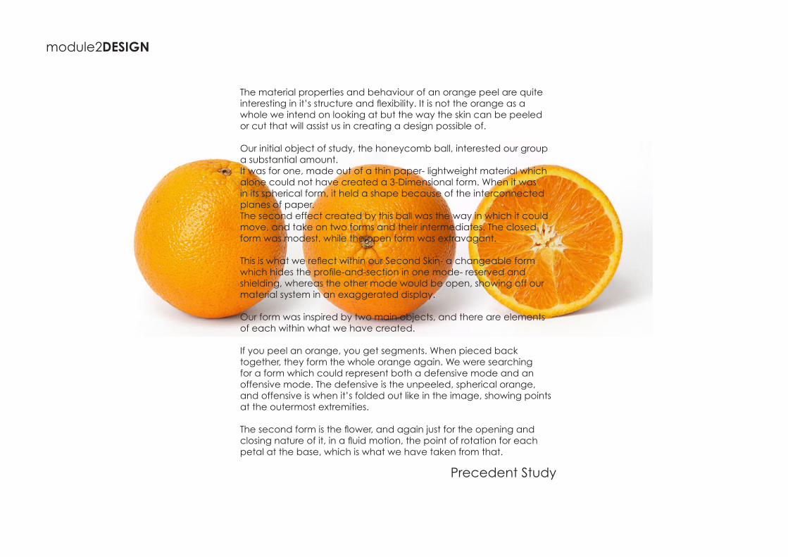
The material properties and behaviour of an orange peel are quite interesting in it’s structure and flexibility. It is not the orange as a whole we intend on looking at but the way the skin can be peeled or cut that will assist us in creating a design possible of.
Our initial object of study, the honeycomb ball, interested our group a substantial amount. It was for one, made out of a thin paper- lightweight material which alone could not have created a 3-Dimensional form. When it was in its spherical form, it held a shape because of the interconnected planes of paper. The second effect created by this ball was the way in which it could move, and take on two forms and their intermediates. The closed form was modest, while the open form was extravagant.
This is what we reflect within our Second Skin- a changeable form which hides the profile-and-section in one mode- reserved and shielding, whereas the other mode would be open, showing off our material system in an exaggerated display.
Our form was inspired by two main objects, and there are elements of each within what we have created.
If you peel an orange, you get segments. When pieced back together, they form the whole orange again. We were searching for a form which could represent both a defensive mode and an offensive mode. The defensive is the unpeeled, spherical orange, and offensive is when it’s folded out like in the image, showing points at the outermost extremities.
The second form is the flower, and again just for the opening and closing nature of it, in a fluid motion, the point of rotation for each petal at the base, which is what we have taken from that.
module2DESIGN
Precedent Study
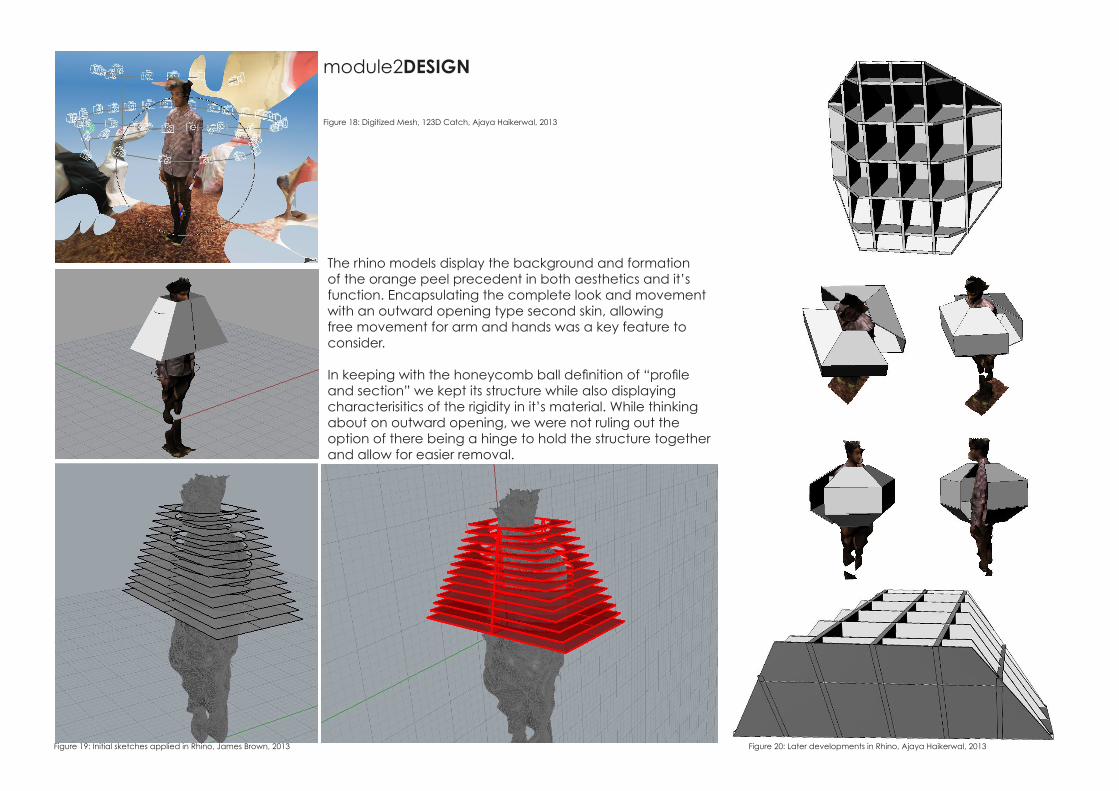
The rhino models display the background and formation of the orange peel precedent in both aesthetics and it’s function. Encapsulating the complete look and movement with an outward opening type second skin, allowing free movement for arm and hands was a key feature to consider.
In keeping with the honeycomb ball definition of “profile and section” we kept its structure while also displaying characterisitics of the rigidity in it’s material. While thinking about on outward opening, we were not ruling out the option of there being a hinge to hold the structure together and allow for easier removal.
module2DESIGN
Figure 18: Digitized Mesh, 123D Catch, Ajaya Haikerwal, 2013
Figure 19: Initial sketches applied in Rhino, James Brown, 2013 Figure 20: Later developments in Rhino, Ajaya Haikerwal, 2013
module2DESIGN
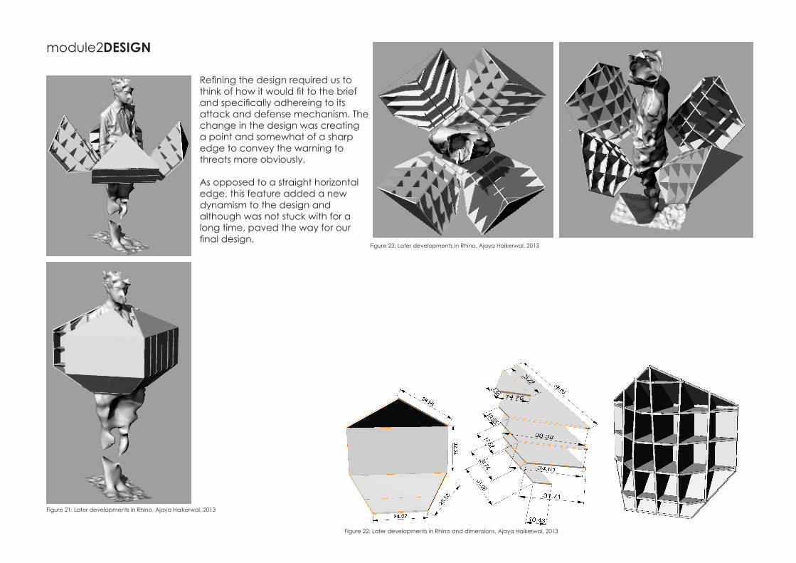
Refining the design required us to think of how it would fit to the brief and specifically adhereing to its attack and defense mechanism. The change in the design was creating a point and somewhat of a sharp edge to convey the warning to threats more obviously.
As opposed to a straight horizontal edge, this feature added a new dynamism to the design and although was not stuck with for a long time, paved the way for our final design.
Figure 21: Later developments in Rhino, Ajaya Haikerwal, 2013
Figure 22: Later developments in Rhino and dimensions, Ajaya Haikerwal, 2013
Figure 23: Later developments in Rhino, Ajaya Haikerwal, 2013
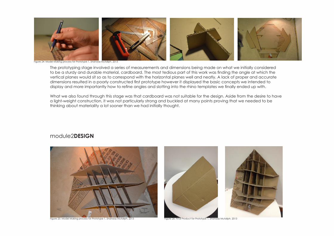
The prototyping stage involved a series of measurements and dimensions being made on what we initially considered to be a sturdy and durable material, cardboard. The most tedious part of this work was finding the angle at which the vertical planes would sit so as to correspond with the horizontal planes well and neatly. A lack of proper and accurate dimensions resulted in a poorly constructed first prototype however it displayed the basic concepts we intended to display and more importantly how to refine angles and slotting into the rhino templates we finally ended up with.
What we also found through this stage was that cardboard was not suitable for the design. Aside from the desire to have a light-weight construction, it was not particularly strong and buckled at many points proving that we needed to be thinking about materiality a lot sooner than we had initially thought.
module2DESIGN
Figure 24: Model Making process for Prototype 1, Shanaaz Mutaliph, 2013
Figure 25: Model Making process for Prototype 1, Shanaaz Mutaliph, 2013 Figure 26: Final Product for Prototype 1, Shanaaz Mutaliph, 2013
module3FABRICATION
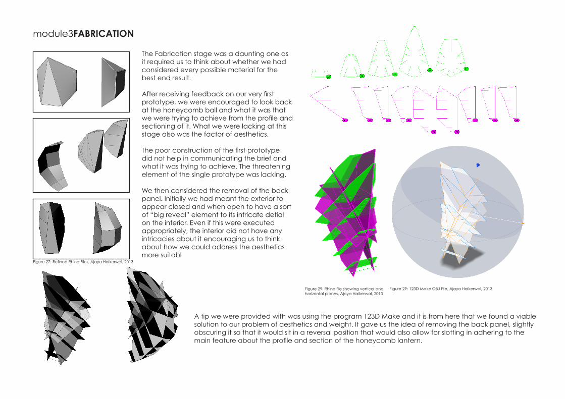
The Fabrication stage was a daunting one as it required us to think about whether we had considered every possible material for the best end result.
After receiving feedback on our very first prototype, we were encouraged to look back at the honeycomb ball and what it was that we were trying to achieve from the profile and sectioning of it. What we were lacking at this stage also was the factor of aesthetics.
The poor construction of the first prototype did not help in communicating the brief and what it was trying to achieve. The threatening element of the single prototype was lacking.
We then considered the removal of the back panel. Initially we had meant the exterior to appear closed and when open to have a sort of “big reveal” element to its intricate detial on the interior. Even if this were executed appropriately, the interior did not have any intricacies about it encouraging us to think about how we could address the aesthetics more suitabl
A tip we were provided with was using the program 123D Make and it is from here that we found a viable solution to our problem of aesthetics and weight. It gave us the idea of removing the back panel, slightly obscuring it so that it would sit in a reversal position that would also allow for slotting in adhering to the main feature about the profile and section of the honeycomb lantern.
Figure 27: Refined Rhino Files, Ajaya Haikerwal, 2013
Figure 29: Rhino file showing vertical and horizontal planes, Ajaya Haikerwal, 2013
Figure 29: 123D Make OBJ File, Ajaya Haikerwal, 2013

Making the move to a more smaller design also allowed us to keep it light-weight and increase number of segments we could use. From 4, it became a light-weight eight piece design. The only problem this posed to us was the mechanism in which it would rotate off an axis to fold outward proving the attack and defense aspect to it.
module3FABRICATION
Figure 30: Rhino file showing on digitized mesh, Ajaya Haikerwal, 2013
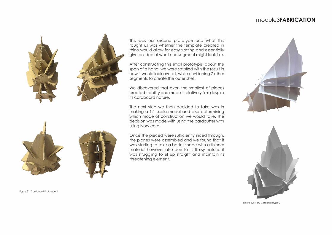
This was our second prototype and what this taught us was whether the template created in rhino would allow for easy slotting and essentially give an idea of what one segment might look like.
After constructing this small prototype, about the span of a hand, we were satisfied with the result in how it would look overall, while envisioning 7 other segments to create the outer shell.
We discovered that even the smallest of pieces created stability and made it relatively firm despire its cardboard nature.
The next step we then decided to take was in making a 1:1 scale model and also determining which mode of construction we would take. The decision was made with using the cardcutter with using ivory card.
Once the pieced were sufficiently sliced through, the planes were assembled and we found that it was starting to take a better shape with a thinner material however also due to its flimsy nature, it was struggling to sit up straight and maintain its threatening element.
module3FABRICATION
Figure 31: Cardboard Prototype 2
Figure 32: Ivory Card Prototype 3
module3FABRICATION
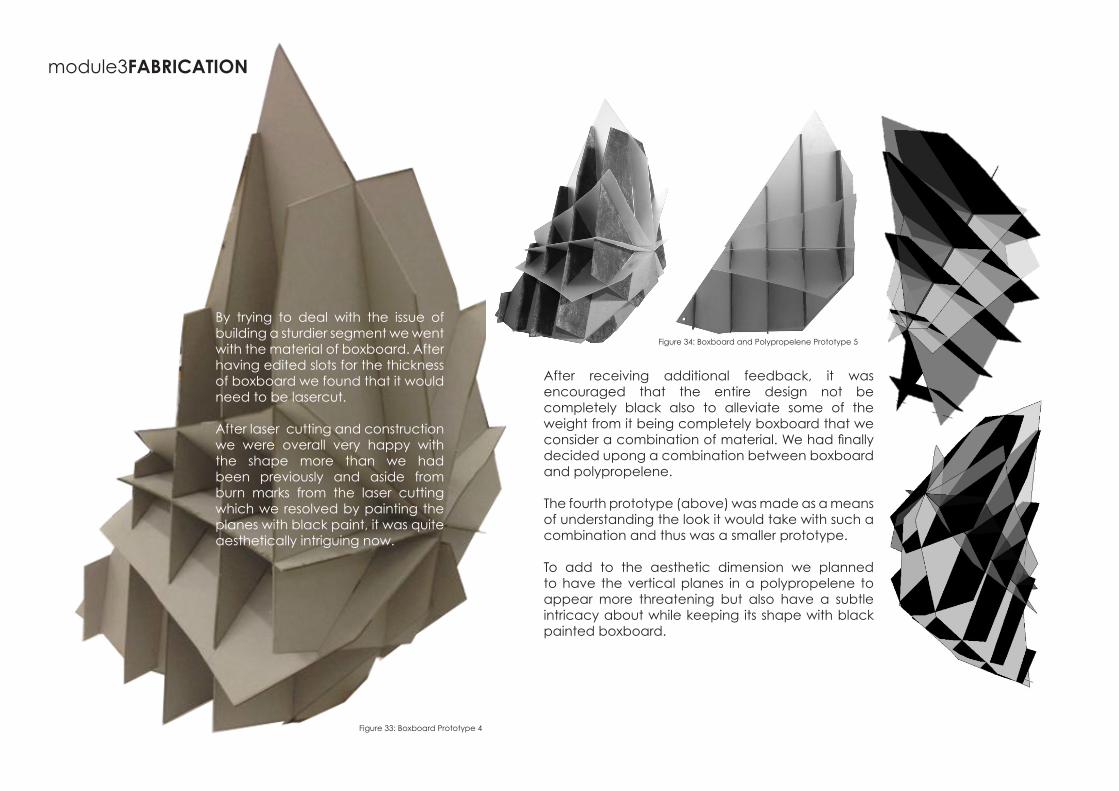
By trying to deal with the issue of building a sturdier segment we went with the material of boxboard. After having edited slots for the thickness of boxboard we found that it would need to be lasercut.
After laser cutting and construction we were overall very happy with the shape more than we had been previously and aside from burn marks from the laser cutting which we resolved by painting the planes with black paint, it was quite aesthetically intriguing now.
After receiving additional feedback, it was encouraged that the entire design not be completely black also to alleviate some of the weight from it being completely boxboard that we consider a combination of material. We had finally decided upong a combination between boxboard and polypropelene.
The fourth prototype (above) was made as a means of understanding the look it would take with such a combination and thus was a smaller prototype.
To add to the aesthetic dimension we planned to have the vertical planes in a polypropelene to appear more threatening but also have a subtle intricacy about while keeping its shape with black painted boxboard.
Figure 33: Boxboard Prototype 4
Figure 34: Boxboard and Polypropelene Prototype 5
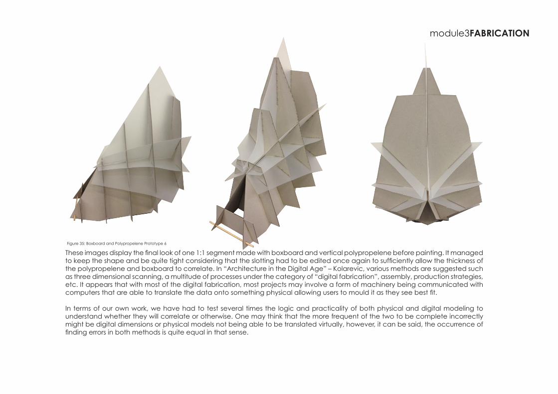
These images display the final look of one 1:1 segment made with boxboard and vertical polypropelene before painting. It managed to keep the shape and be quite tight considering that the slotting had to be edited once again to sufficiently allow the thickness of the polypropelene and boxboard to correlate. In “Architecture in the Digital Age” – Kolarevic, various methods are suggested such as three dimensional scanning, a multitude of processes under the category of “digital fabrication”, assembly, production strategies, etc. It appears that with most of the digital fabrication, most projects may involve a form of machinery being communicated with computers that are able to translate the data onto something physical allowing users to mould it as they see best fit.
In terms of our own work, we have had to test several times the logic and practicality of both physical and digital modeling to understand whether they will correlate or otherwise. One may think that the more frequent of the two to be complete incorrectly might be digital dimensions or physical models not being able to be translated virtually, however, it can be said, the occurrence of finding errors in both methods is quite equal in that sense.
module3FABRICATION
Figure 35: Boxboard and Polypropelene Prototype 6
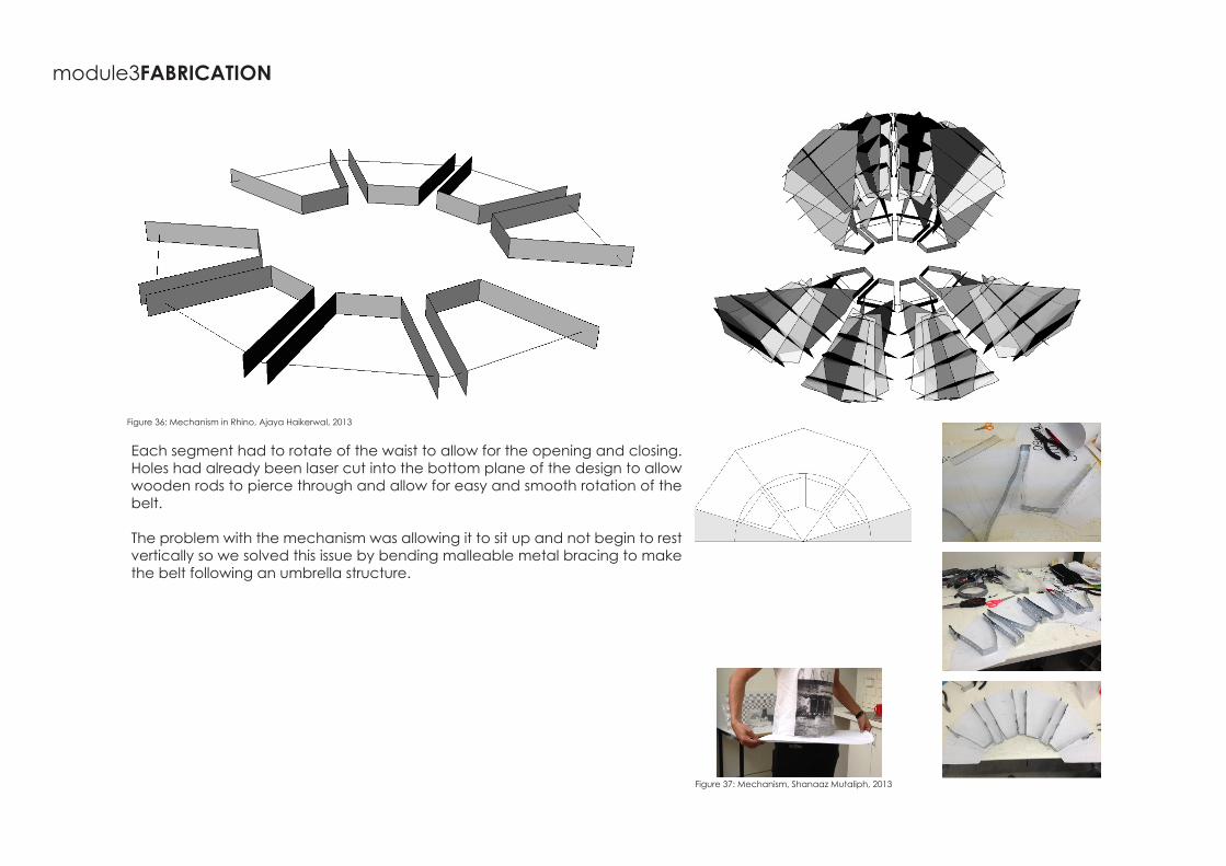
Each segment had to rotate of the waist to allow for the opening and closing.Holes had already been laser cut into the bottom plane of the design to allow wooden rods to pierce through and allow for easy and smooth rotation of the belt.
The problem with the mechanism was allowing it to sit up and not begin to rest vertically so we solved this issue by bending malleable metal bracing to make the belt following an umbrella structure.
module3FABRICATION
Figure 36: Mechanism in Rhino, Ajaya Haikerwal, 2013
Figure 37: Mechanism, Shanaaz Mutaliph, 2013
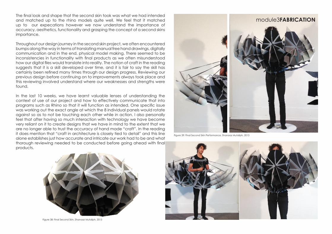
The final look and shape that the second skin took was what we had intended and matched up to the rhino models quite well. We feel that it matched up to our expecations however we now understand the importance of accuracy, aesthetics, functionality and grasping the concept of a second skins importance.
Throughout our design journey in the second skin project, we often encountered bumps along the way in terms of translating manual free hand drawings, digitally communication and in the end, physical model making. There seemed to be inconsistencies in functionality with final products as we often misunderstood how our digital files would translate into reality. The notion of craft in the reading suggests that it is a skill developed over time, and it is fair to say the skill has certainly been refined many times through our design progress. Reviewing our previous design before continuing on to improvements always took place and this reviewing involved understand where our weaknesses and strengths were found.
In the last 10 weeks, we have learnt valuable lenses of understanding the context of use of our project and how to effectively communicate that into programs such as Rhino so that it will function as intended. One specific issue was working out the exact angle at which the 8 individual panels would rotate against so as to not be touching each other while in action. I also personally feel that after having so much interaction with technology we have become very reliant on it to create designs that we have in mind to the extent that we are no longer able to trust the accuracy of hand made “craft”. In the reading it does mention that “craft in architecture is closely tied to detail” and this line alone establishes just how accurate and intricate our work had to be and what thorough reviewing needed to be conducted before going ahead with final products.
Figure 38: Final Second Skin, Shanaaz Mutaliph, 2013
Figure 39: Final Second Skin Performance, Shanaaz Mutaliph, 2013
module3FABRICATION
Bibliography
Bernstein, P & Dreamer, P 2008, Building the Future: Recasting Labor in Architecture, Princeton Architectural Press
Iwamoto, L 2009, Digital Fabrications: architectural and material techniques, Princeton Architectural Press, New York
Kolarevic, B 2003, Architecture in the Digital Age - Design and Manufacturing, Spon Press, London
Miralles, E & Pinos, C 1991, How to lay out a croissant, En Construccion
Rifkin, J 2001, The Third Industrial Revolution, Palgrave Macmillan, Basingstoke