Embed Size (px)
Citation preview

M320 Series
M320 Series Special Inverter for Plastic Machine 1
SHENZHEN SUNFAR ELECTRIC TECHNOLOGIES CO.,LTD
M320 Series Special Inverter for Plastic Machine
Manual

M320 Series
M320 Series Special Inverter for Plastic Machine 2
PREFACE
Thank you very much for choosing M320 series special inverter for plastic machine.
This manual provides guidance of using the inverter safely and carefully, containing
introduction of installation, wiring, parameters list, routine maintenance, operating rules and
cautions, etc.
In order to make good use of the inverter properly and safely, please read this manual
thoroughly before using. It may lead to abnormal operation and failure, reduce using life, even
damage the equipment and cause personal injury if you use it wrongly.
This manual is attachment together with the inverter. Please keep it well and it would be
available to engineering and installation personnel, repairing and maintaining during the
product functioning period. SUNFAR has the right to modify and ameliorate products, data
and dimensions without notice, so this manual is updated and all the contents in this manual
are subject to change without any notice.
SHENZHEN SUNFAR ELECTRIC TECHNOLOGIES CO., Ltd.

M320 Series
M320 Series Special Inverter for Plastic Machine 3
CONTENT 1 INTRODUCTION…………………………………………………………………………………………………
1.1 Series ……………………………………………………………………………………………………………
1.2 Appearance ……………………………………………………………………………………………………
1.3 Model……………………………………………………………………………………………………………
1.4 Specification…………………………………………………………………………………………………………
2 INSTALLATION……………………………………………………………………………………………………………
2.1 Environmental requirements …………………………………………………………………………………
2.2 Installation Dimension ………………………………………………………………………………………
3 WIRING ………………………………………………………………………………………………………………………
3.1 Precautions ………………………………………………………………………………………………………
3.2 Wiring of External Components ……………………………………………………………………………
3.3 Basic Wiring …………………………………………………………………………………………………………
3.4 Wiring of Main Loop Terminal …………………………………………………………………………………
3.5 Wiring of Control Loop Terminal ………………………………………………………………………
4 PANEL OPERATION …………………………………………………………………………………………………
4.1 Operation Panel ……………………………………………………………………………………………
4.2 Basic Function and Operation ………………………………………………………………………………
4.3 State Monitor Parameter List …………………………………………………………………………………
5 PARAMETER LIST …………………………………………………………………………………………………………
6 DESCRIPTION OF SPECIFIC
FUNCTION ………………………………………………………………………………………………………………
6.1 Basic Operation Parameter Unit ………………………………………………………………………………
6.2 Primary Applied Parameter Unit ………………………………………………………………………………
6.3 Analog Input & Output Parameter Unit ………………………………………………………………
6.4 Digital O/I Parameter Unit ………………………………………………………………………………………
6.5 Auxiliary Running Parameter Unit ……………………………………………………………………
6.6 Communication Function Parameter
Unit …………………………………………………………………………………………………………………………
6.7 Special Function Parameter Unit……………………………………………………………………………
7 FAULT DIAGNOSIS AND
COUNTERMEASURES ………………………………………………………………………………………………
7.1 Protective functions and
7
7
7
8
8
10
10
10
12
12
12
14
14
15
17
17
18
20
22
26
26
30
32
34
37
41
43
45
M320 Series
M320 Series Special Inverter for Plastic Machine 4
Countermeasures ………………………………………………………………………………………………………
7.2 Fault record inquiry ……………………………………………………………………………………………
7.3 Reset ……………………………………………………………………………………………………………………
8 MAINTENANCE ……………………………………………………………………………………………………
8.1 Daily Maintenance …………………………………………………………………………………………………
8.2 Damageable parts maintenance ………………………………………………………………………
8.3 Storage…………………………………………………………………………………………………………………
8.4 After sale services ……………………………………………………………………………………………
9 USAGE EXAMPLE ……………………………………………………………………………………………………
9.1 Panel on-off control, Panel potentiometer setting
frequency…………………………………………………………………………………………………………………
9.2 External on-off control mode, external voltage setting
frequency……………………………………………………………………………………………………………
45
46
46
48
48
48
49
49
50
50
50
M320 Series
M320 Series Special Inverter for Plastic Machine 5
PRECAUTIONS
M320 series is special inverter for plastic machine which applies in common industry three
phase AC asynchronous motor, as plastic extrusion machine. If used for some dangerous
devices, there should be safe protection measures to avoid expanding accident. In order to
use the inverter properly and safely, please read this manual carefully before using. Please
follow the requirements of this manual to move, install, run, operate and repair the inverter. 1. Opening
ⅠPlease check any damage that may have occurred during transportation.
ⅡPlease check whether the nameplate data of inverter is in accordance with your order, if
anything wrong, please contact supplier immediately.
Our product is manufactured, packed and transported in the strict quality system. But in case
there is any error, please contact with our company or local agent, we will solve the problem
as quickly as possible.
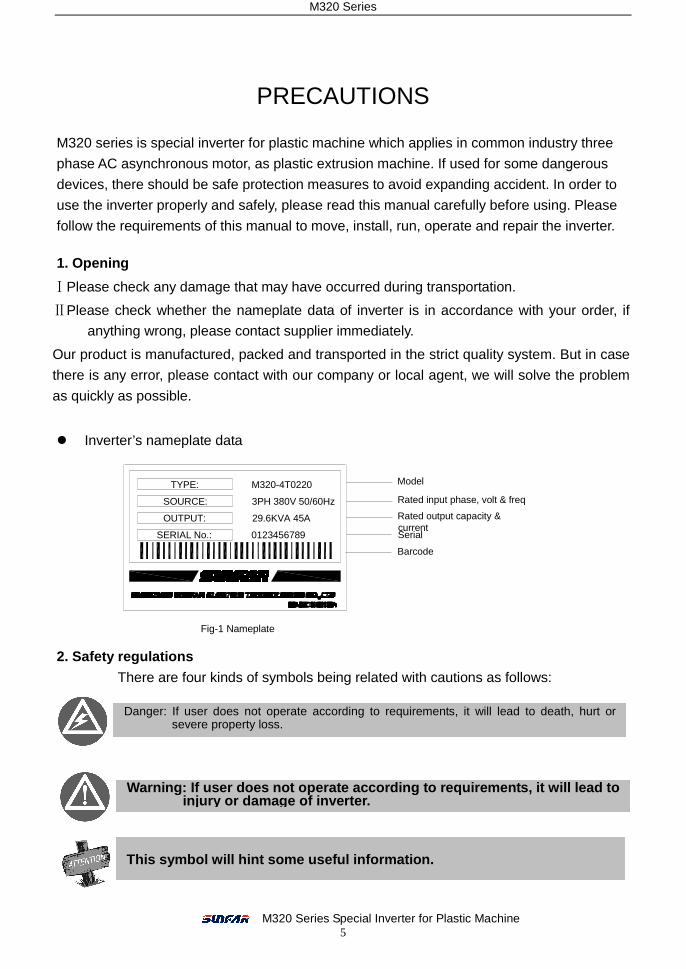
� Inverter’s nameplate data
2. Safety regulations
There are four kinds of symbols being related with cautions as follows:
Fig-1 Nameplate
Danger: If user does not operate according to requirements, it will lead to death, hurt or severe property loss.
Warning: If user does no t operate according to requirements, it will lead t o injury or damage of inverter.
This symbol will hint some useful information.
SERIAL No.:
SOURCE:
OUTPUT:
TYPE:
0123456789
M320-4T0220
3PH 380V 50/60Hz
29.6KVA 45A
Model
Rated input phase, volt & freq
Rated output capacity & currentSerial
Barcode
M320 Series
M320 Series Special Inverter for Plastic Machine 6
2.1 Installing 2.1.1. Do not put the inverter on the combustible material. 2.1.2. M320 series inverter can’t install in the explosive ambient. 2.1.3. Do not drop other material into the inverter.
2.2 Wiring 2.2.1. It must be operated by professional worker when wiring.
2.2.2. Please be sure to turn off the power supply at least 10 min before wiring.
2.2.3. Inverter and motor must be grounded correctly.
2.2.4. Be sure to wire or inspect the inverter after power-off at least 10 minutes.
2.2.5. Electron components are sensitive about static electricity, so do not drop other
material in inverter or touch the main circuit.
2.3 Maintenance
3. Attention Notes:
3.1. Be sure to install the inverter in a well-ventilated ambient. 3.2. The temperature at variable-frequency will be higher than at line-frequency, which is
normal phenomenon. 3.3. The ordinary motor cannot run in the low speed for a long time, so user should select
the special motor for inverter or reduce the motor load under the low speed. 3.4. When the altitude is over 1000m, the inverter will be valid to decrease the rated
current, and the rated current will decrease 10% when the attitude is increased 1500m.
4 Dispose: When you dispose inverter and its parts, please pay attention to: Capacitor: The capacitors in inverter may explode when they are burned. Plastic: Poisonous gas may be generated when the front panel is burned, please pay attention to the waste gas when the plastic parts are burned. Method: Please dispose inverter as industry rubbish.
It is forbidden to connect an AC power supply with the U, V and W output terminals directly
1. Do not touch the radiator after power-off at least 10 minutes. 2. The earth terminal of inverter must be connected to ground reliably.
It is forbidden to disassemble and refit the inverter.
Be sure not to connect the output terminals of inverter with the filter capacitors and other surge absorbers.
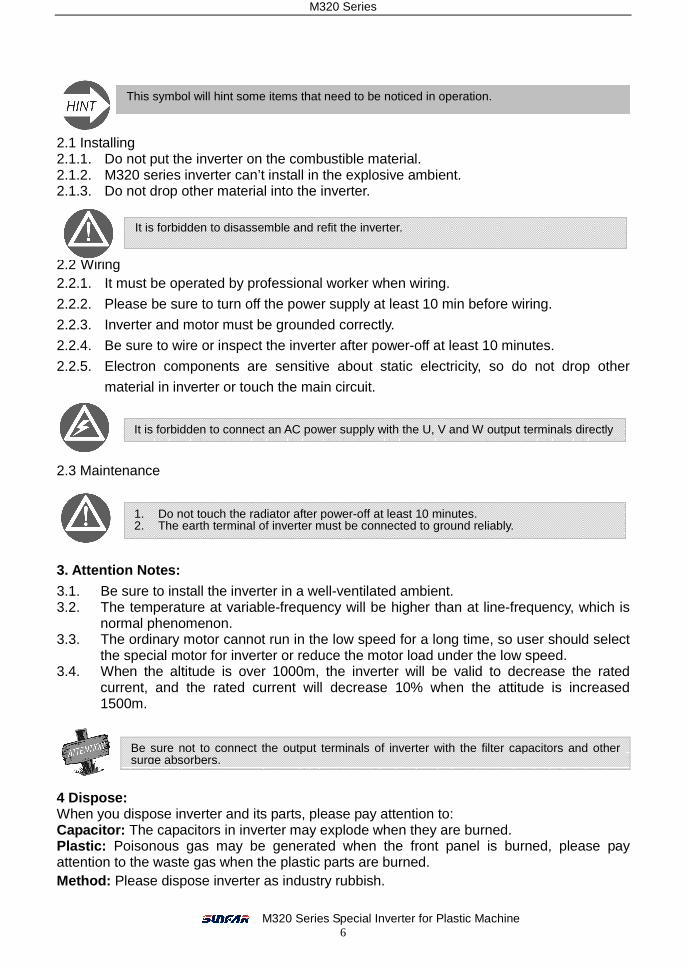
This symbol will hint some items that need to be noticed in operation.

M320 Series
M320 Series Special Inverter for Plastic Machine 7
Cable Entrance of Control Loop
Bottom Installation Hole
Cable Entrance of Main Loop
Cover
Operation Panel
Shell Control Panel Interface
Remote-line Interface
Control Loop Terminal
Main Loop Terminal
WARNING!
2.Do not connect AC power to output terminals UVW.
4.Securely ground(earth) the equipment.
3.Do not remove any cover while applying power
1.Refer to the instruction manual before installation
and at least 10min. after disconnecting power.
and operation.
M320
Operation Panel
Above Cover
Below Cover
Control Loop TerminalMain Loop Terminal
1. INTRODUCTION 1.1 Series
1.2 Appearance
1.2.1 TypeⅠ
Fit models:M320-4T0015~M320-4T0075 / M320-2T0015~M320-2T0037
1.2.2 Type Ⅱ
Fit models: M320-4T0110~M320-4T0900 / M320-2T0055~M320-2T0550
Fig 1-2 Part Name for Type Ⅱ
Series
M320 Special Inverter
for Plastic Machine
E380 Integrated Universal Inverter
H320 High Speed
Inverter
C300
Mini-type Sensorless
Vector Control Inverter
C320 Sensorless
Vector Control Inverter
Voltage
2 220V
4 380V
Power Phase
T 3 PH
S Single Phase
Power(KW)
0015 0022 0037 0055 0075 0110 . . .
0750 0900
1.5 2.2 3.7 5.5 7.5 11 . . .
75 90
M320– 4 T 0055
Fig 1-1 Part Name for TypeⅠ
M320 Series
M320 Series Special Inverter for Plastic Machine 8
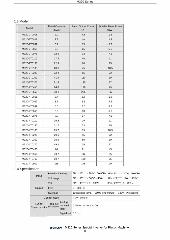
1.3 Model
Model Rated Capacity
(KVA)
Rated Output Current
(A)
Suitable Motor Power
(KW)
M320-2T0015 2.9 7.5 1.5
M320-2T0022 3.8 10 2.2
M320-2T0037 5.7 15 3.7
M320-2T0055 9.5 25 5.5
M320-2T0075 12.6 33 7.5
M320-2T0110 17.5 46 11
M320-2T0150 22.9 60 15
M320-2T0185 28.6 75 18.5
M320-2T0220 32.4 85 22
M320-2T0300 41.9 110 30
M320-2T0370 51.5 135 37
M320-2T0450 64.8 170 45
M320-2T0550 78.1 205 55
M320-4T0015 2.4 3.7 1.5
M320-4T0022 3.6 5.5 2.2
M320-4T0037 5.6 8.5 3.7
M320-4T0055 8.6 13 5.5
M320-4T0075 11 17 7.5
M320-4T0110 16.5 25 11
M320-4T0150 21.7 33 15
M320-4T0185 25.7 39 18.5
M320-4T0220 29.6 45 22
M320-4T0300 39.5 60 30
M320-4T0370 49.4 75 37
M320-4T0450 60 91 45
M320-4T0550 73.7 112 55
M320-4T0750 98.7 150 75
M320-4T0900 116 176 90
1.4 Specification Rated volt & freq. 3Ph(4T****)380V;50/60Hz 3Ph(2T****)220V; 50/60Hz
Input Volt range 3Ph(4T****)300V ~ 460V 3Ph(2T****)170V~270V
Volt 3Ph(4T****)0 ~ 380V 3Ph ( 2T**** ) 0~220 V
Freq. 0~200 Hz Output
Overload 110%: long-term; 150%: one minute; 180%: two second
Control mode VVVF control
Analog terminal input
0.1% of max output freq. Control
CharacteristicsFreq. set resolution
Digital set 0.01Hz

M320 Series
M320 Series Special Inverter for Plastic Machine 9
External pulse
0.1% of max freq.
Analog
input Within 0.2% of max output freq.
Digital
input Within 0.01% of set output freq.
Freq. precision
External pulse
Within 0.1% of max output freq.
V/F curve (Volt-freq. characteristics)
Set freq. between standard 5 to 200Hz and multimode V/F curve freely.
Torque boost Manual set: 0.0~20.0% of rated output
Auto limited current & volt
Check current and volt automatically during acc, dec or stable running which would be controlled within allowable range with special algorithm.
Inhibit volt lack during running
Special for lower power and volt fluctuation, even if lower than allowed volt, the system will maintain the longest running time.
Analog
input DC volt: 0~5V、0~10V,DC current: 0~20mA
Pulse input
Amplitude Value: 5 ~ 30V (pulse signal of Freq. within 50.0KHz)
Freq. set
Digital
input
Operation panel & RS485 interface set, UP/DW terminal
control, multi combination set with analog input.
OC terminal output
Two OC outputs & one relay failure output (TA,TB,TC)reach 16 meaning choices. Output
signal Analog output
Two 0~10V volt signals or 0~20mA current signals can be set upper and lower limit.
Auto stabilizing volt
running
Three ways for selection: dynamic and static voltage regulation, non voltage regulation in order to achieve the most credible running.
Set acc. & dec time 0.1S~6000min continuous set, S and linear type available
Typical
function
Running function Upper & lower freq. set, freq. skip running, limitation of rev.
running, auto stabilizing volt running, RS485 communication, freq. increasing/ decreasing control etc.
Running stage
Output freq., current and volt, motor rotational speed, freq. set, module temperature, feedback, analog input and output etc.
Display
Operation panel
display Warning
content
Latest six failure records, output freq. of the last failure, freq. set, output current and volt, DC volt, module temperature etc.
Protection/ warning function Over current & volt, under volt, electronic thermal relay, overheat, shortcut, failure of inner memorizer etc.
Ambient temperature -10ºC to +50ºC
Ambient humidity Below 90%
Ambient environment Indoor (no direct sunshine, non-corrosive, no inflammable gas, oil, dust etc.)
Environment
Altitude Below 1000m
Protection grade IP20 Configuration
Cooling way Forced cooling
Installation Hang

M320 Series
M320 Series Special Inverter for Plastic Machine 10
2. Installation 2.1 Environmental requirements: It should be hanging vertically in order to ventilation and radiating.
If there is any special installation requirement, please inform us firstly. M320 series inverter is hanging model, so it should be in vertical. To ensure ventilation around the inverter to radiate, there should be enough space shown as Fig. 2-1-A. Air deflector when apply the up-down installation shown as Fig. 2-1-B.
2.2 Installation Dimension 2.2.1 SizeⅠⅠⅠⅠ
1. Be sure to install the inverter in a well-ventilated room. 2. Ambient temperature is from -10 to 40 . If the temperature ℃ ℃
is 40 to 50 , please take out the lower cover to cool.℃ ℃ 3. Please avoid putting the inverter in a high temperature and
moist location. The humidity is less than 90% and non-condensing.
4. Keep away from combustible, explosive material and caustic gas or liquid.
5. No dust, floating fiber and metal particles 6. The inverter must be installed in a firm and no vibration
location. 7. The installation plane should be solid and not vibrant.
Air deflector
Fig2-1-B Multi-inverter Installation Fig2-1-A Interval distance
Fit model:
M320-4T0015~M320-4T0075 /
M320–2T0015~M320–2T0037,
Shown as Fig. 2-2-A
50mm以上
WARNING!
2.Do not connect AC power to output terminals UVW.
4.Securely ground(earth) the equipment.
3.Do not remove any cover while applying power
1.Refer to the instruction manual before installation
and at least 10min. after disconnecting power.
and operation.
M320
Fan
Abo
ve 1
20m
mA
bove
120
mm
50mm以上
Fig. 2-2-A Installation Dimension
DW1
W
H H1
RUN
Hz
V
A
M320
M320 Series
M320 Series Special Inverter for Plastic Machine 11
M320
D
H H1
W
and operation.
and at least 10min. after disconnecting power.
1.Refer to the instruction manual before installation
3.Do not remove any cover while applying power
4.Securely ground(earth) the equipment.
2.Do not connect AC power to output terminals UVW.
! WARNING
W1
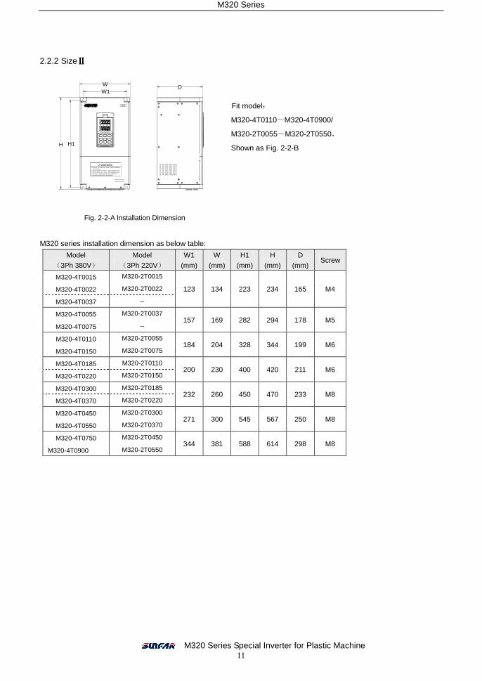
2.2.2 SizeⅡⅡⅡⅡ
M320 series installation dimension as below table: Model
(3Ph 380V)
Model
(3Ph 220V)
W1
(mm)
W
(mm)
H1
(mm)
H
(mm)
D
(mm) Screw
M320-4T0015 M320-2T0015
M320-4T0022 M320-2T0022
M320-4T0037 --
123 134 223 234 165 M4
M320-4T0055 M320-2T0037
M320-4T0075 -- 157 169 282 294 178 M5
M320-4T0110 M320-2T0055
M320-4T0150 M320-2T0075 184 204 328 344 199 M6
M320-4T0185 M320-2T0110
M320-4T0220 M320-2T0150 200 230 400 420 211 M6
M320-4T0300 M320-2T0185
M320-4T0370 M320-2T0220 232 260 450 470 233 M8
M320-4T0450 M320-2T0300
M320-4T0550 M320-2T0370 271 300 545 567 250 M8
M320-4T0750 M320-2T0450
M320-4T0900 M320-2T0550 344 381 588 614 298 M8
Fig. 2-2-A Installation Dimension
Fit model:
M320-4T0110~M320-4T0900/
M320-2T0055~M320-2T0550,
Shown as Fig. 2-2-B
M320 Series
M320 Series Special Inverter for Plastic Machine 12
Inverter U
V
W
M
Motor
RC absorb device
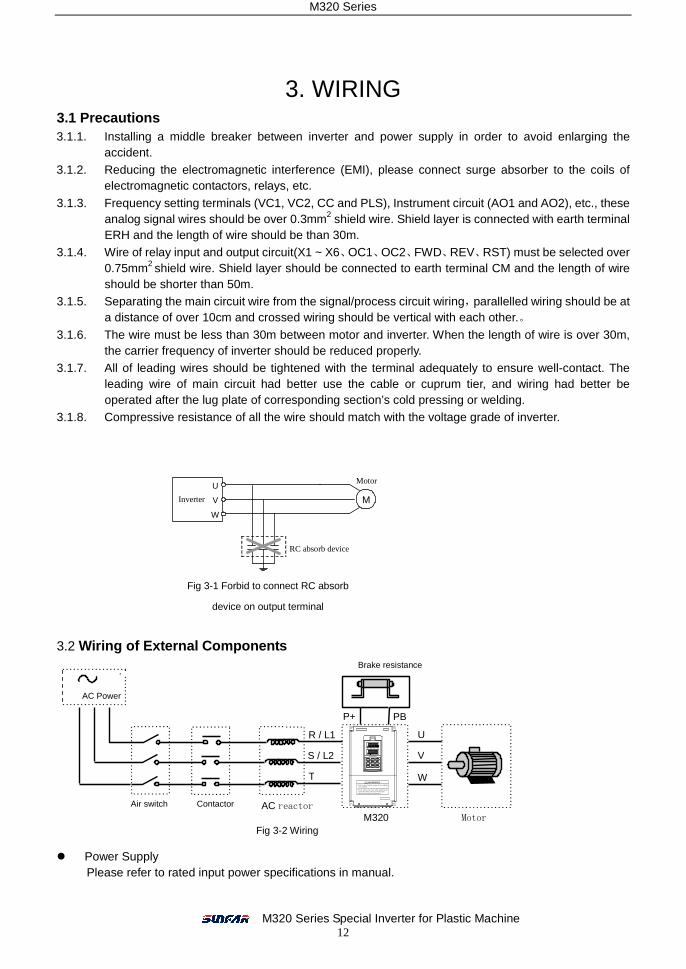
3. WIRING
3.1 Precautions 3.1.1. Installing a middle breaker between inverter and power supply in order to avoid enlarging the
accident. 3.1.2. Reducing the electromagnetic interference (EMI), please connect surge absorber to the coils of
electromagnetic contactors, relays, etc.
3.1.3. Frequency setting terminals (VC1, VC2, CC and PLS), Instrument circuit (AO1 and AO2), etc., these analog signal wires should be over 0.3mm2 shield wire. Shield layer is connected with earth terminal ERH and the length of wire should be than 30m.
3.1.4. Wire of relay input and output circuit(X1 ~ X6、OC1、OC2、FWD、REV、RST) must be selected over 0.75mm2 shield wire. Shield layer should be connected to earth terminal CM and the length of wire should be shorter than 50m.
3.1.5. Separating the main circuit wire from the signal/process circuit wiring,parallelled wiring should be at a distance of over 10cm and crossed wiring should be vertical with each other.。
3.1.6. The wire must be less than 30m between motor and inverter. When the length of wire is over 30m, the carrier frequency of inverter should be reduced properly.
3.1.7. All of leading wires should be tightened with the terminal adequately to ensure well-contact. The leading wire of main circuit had better use the cable or cuprum tier, and wiring had better be operated after the lug plate of corresponding section’s cold pressing or welding.
3.1.8. Compressive resistance of all the wire should match with the voltage grade of inverter.
3.2 Wiring of External Components
� Power Supply
Please refer to rated input power specifications in manual.
Fig 3-1 Forbid to connect RC absorb
device on output terminal
Brake resistance
Motor
R / L1
S / L2
T
U
V
W
AC reactor
M320
AC Power
P+ PB
Air switch Contactor
Fig 3-2 Wiring
and operation.
and at least 10min. after disconnecting power.
1.Refer to the instruction manual before installat ion
3.Do not remove any cover while applying power
4.Securely ground(earth) the equipment.
2.Do not connect AC power to output terminals UVW.
! WARNING
M320 Series
M320 Series Special Inverter for Plastic Machine 13
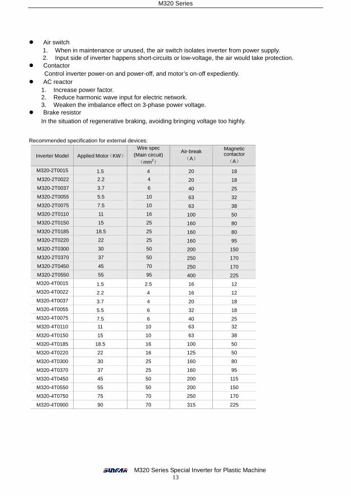
� Air switch 1. When in maintenance or unused, the air switch isolates inverter from power supply. 2. Input side of inverter happens short-circuits or low-voltage, the air would take protection.
� Contactor Control inverter power-on and power-off, and motor’s on-off expediently.
� AC reactor 1. Increase power factor. 2. Reduce harmonic wave input for electric network. 3. Weaken the imbalance effect on 3-phase power voltage.
� Brake resistor In the situation of regenerative braking, avoiding bringing voltage too highly.
Recommended specification for external devices:
Inverter Model Applied Motor(KW)
Wire spec (Main circuit) (mm2)
Air-break (A)
Magnetic contactor (A)
M320-2T0015 1.5 4 20 18
M320-2T0022 2.2 4 20 18
M320-2T0037 3.7 6 40 25
M320-2T0055 5.5 10 63 32
M320-2T0075 7.5 10 63 38
M320-2T0110 11 16 100 50
M320-2T0150 15 25 160 80
M320-2T0185 18.5 25 160 80
M320-2T0220 22 25 160 95
M320-2T0300 30 50 200 150
M320-2T0370 37 50 250 170
M320-2T0450 45 70 250 170
M320-2T0550 55 95 400 225
M320-4T0015 1.5 2.5 16 12
M320-4T0022 2.2 4 16 12
M320-4T0037 3.7 4 20 18
M320-4T0055 5.5 6 32 18
M320-4T0075 7.5 6 40 25
M320-4T0110 11 10 63 32
M320-4T0150 15 10 63 38
M320-4T0185 18.5 16 100 50
M320-4T0220 22 16 125 50
M320-4T0300 30 25 160 80
M320-4T0370 37 25 160 95
M320-4T0450 45 50 200 115
M320-4T0550 55 50 200 150
M320-4T0750 75 70 250 170
M320-4T0900 90 70 315 225

M320 Series
M320 Series Special Inverter for Plastic Machine 14
3.3 Basic Wiring
3.4 Wiring of Main Loop Terminal
3.4.1 Type I
3.4.2 Type II
3.4.3 Type III
Fig 3-3 Basic Wiring
P+ P - R S T U V W PB E
Motor
3-phase power supply
Brake resistance
Earth
DC reactor
Brake Unit
Brake resistance
Motor 3-phase power
P P+ P- R S T U V W PB E
Earth
R S T P P+ P- U V W E
Motor 3-phase power
Earth
Brake Unit
DC reactor
Fit model:
M320-4T0015~M320-4T0075 /
M320-2T0015~M320-2T0037
Fit model:
M320-4T0110~M320-4T0185 /
M320-2T0055~M320-2T0075
Fit model:
M320-4T0220~M320-4T0370 /
M320-2T0110~M320-2T0220
M
Motor
Ta
Tb
Tc
U
W
V
R
S
T
FWD
REV
CM
AO1
AO2
GND
Fault alarm
Voltmeter(0~10V)/ Current meter(0~20mA)
E
X1
X2
X3
X4
X5
X6
CM
RST
VS
VC1
CC
P-
PB External brake resistor
Open-circuit Collector output
OC1
OC2
CM
Earth
× × ×
P
24V Auxiliary DC power
0 ~ 10V Frequency set
0 ~ 5V Frequency set
VC2
GND
0 ~ 20mA Frequency set
Voltmeter(0~10V)/ Current meter(0~20mA)
PLS
CM
0 ~ 50KHz Frequency set
Three-phase Breaker
Three-phase Power supply
PLC input terminal
FWD Order
REV Order
Fault Reset
M320 Series
M320 Series Special Inverter for Plastic Machine 15
X1 X3 X5 CM RST 24V OC2 PLS CC GND AO2
+ X2 X4 FWD REV OC1 VS VC1 VC2 AO1 ERH TA TB TC - X6
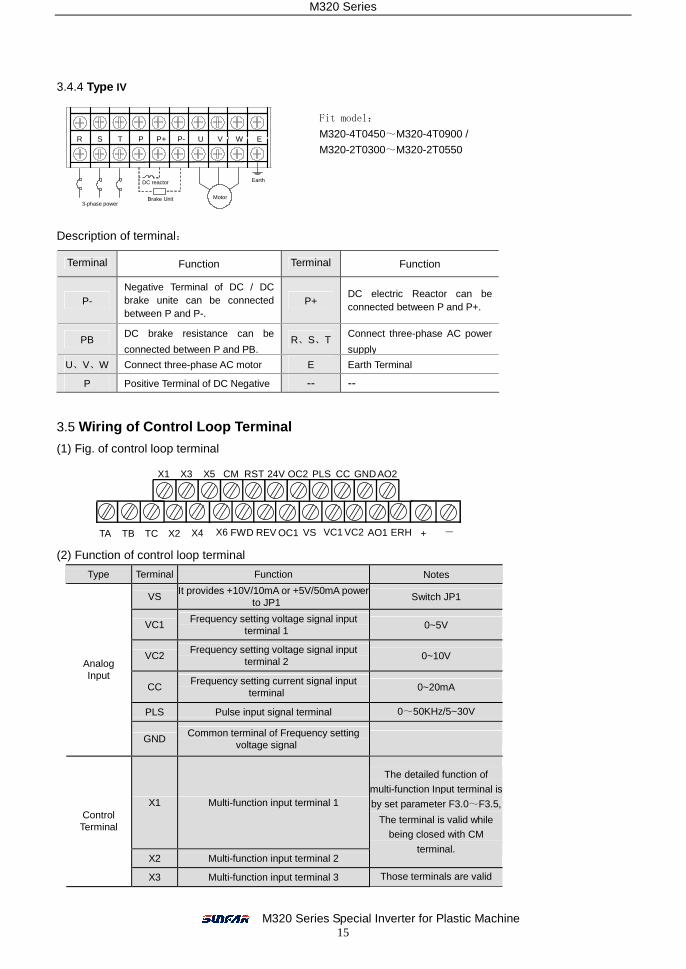
3.4.4 Type IV
Description of terminal:
3.5 Wiring of Control Loop Terminal
(1) Fig. of control loop terminal
(2) Function of control loop terminal
Type Terminal Function Notes
VS It provides +10V/10mA or +5V/50mA power
to JP1 Switch JP1
VC1 Frequency setting voltage signal input
terminal 1 0~5V
VC2 Frequency setting voltage signal input
terminal 2 0~10V
CC Frequency setting current signal input
terminal 0~20mA
PLS Pulse input signal terminal 0~50KHz/5~30V
Analog Input
GND Common terminal of Frequency setting
voltage signal
X1 Multi-function input terminal 1
X2 Multi-function input terminal 2
The detailed function of
multi-function Input terminal is
by set parameter F3.0~F3.5,
The terminal is valid while being closed with CM
terminal.
Control Terminal
X3 Multi-function input terminal 3 Those terminals are valid
when it connects with CM.
Terminal Function Terminal Function
P- Negative Terminal of DC / DC brake unite can be connected between P and P-.
P+ DC electric Reactor can be connected between P and P+.
PB DC brake resistance can be
connected between P and PB. R、S、T
Connect three-phase AC power
supply
U、V、W Connect three-phase AC motor E Earth Terminal
P Positive Terminal of DC Negative -- --
R S T P P+ P- U V W E
Motor 3-phase power
Earth
Brake Unit
DC reactor
Fit model:
M320-4T0450~M320-4T0900 /
M320-2T0300~M320-2T0550

M320 Series
M320 Series Special Inverter for Plastic Machine 16
X4 Multi-function input terminal 4
X5 Multi-function input terminal 5
X6 Multi-function input terminal 6
FWD FWD control command terminal
REV REV control command terminal
RST Fault reset input terminal
CM Common terminal of control
Control Terminal
24V It provides +24V/50mA power and is
grounded by CM.
AO1 PLC voltage signal input terminal1. It is set
by F2.13 and allowed to connect with external voltmeter.
AO2 PLC voltage signal input terminal 2. It is set
by F2.14 and allowed to connect with external voltmeter.
Analog Output
GND Common terminal of AM1and AM2
voltage signal output :
0~20mA/0~15V.
Voltage signal output :
0~10V/1mA
Switch JP2、JP3 select
voltage or current
OC1 PLC open-circuit collector output is set by
F3.6 and F3.7 OC Output
OC2
The maximum load-current is
50mA, while the maximum
withstand voltage is 24V.
TA
General , TA-TB is connected,TA-Tc is unconnected
when TA-TB is unconnected and TA-TC is connected,F3.8 is valid.
TB
Programm- able
output
TC
Capacity:AC 250V 1A
Resistive load
+ RS485 interface RS485 Interface
-
ERH Grounding terminal
Explanation for JP:
+5V
+10
V
JP1 JP2
VO
2
VO
1
JP3
CO
1
CO
2
JP1: 1-2shorted:Input +5V/50mA signal
2-3shorted:Input +10V/10mA signal JP2: 1-2 shorted:AO1input voltage signal
2-3 shorted:AO1 input current signal
JP3: 1-2 shorted:AO2 input voltage signal
2-3 shorted:AO2 input current signal

M320 Series
M320 Series Special Inverter for Plastic Machine 17
<<
RUN Hz A V
ESC JOG
SET REV FWD
STOP
lightRunning
Set
Return
Increasing
Decreasing
Main LED
Digital displayData unit
Auxiliary LED
SwitchJogFWDREVStop
RUN
Hz A
VIndicate Light
Main LED
Return
Set
Increasing
Decreasing
Digital display Data unit
Potentiometer
Switch
FWD
REV
Stop
4. PANEL OPERATION Operation panel has two functions:One is to modify the running state parameters, another is to check and
modify inner parameters. So operation panel has two modes : Modify mode, check and modify parameters
mode.
Usually, operation panel mode is normal modify mode when power-on. At this time, current running
parameter, which is shown on operation panel, is controlled by F4.21 and F4.22. The operation panel mode
will return normal modify mode, if there isn’t any operation on panel within 1 min.
4.1 Operation Panel 4.1.1 Explanation
4.1.2 Function
Item Function
Main LED It displays current state and setting parameter.
Auxiliary LED It displays current state and setting parameter. When power-on, it displays inverter’s program version, and it will return normality within 2 second. Small panel doesn’t have this auxiliary LED.
A、Hz、V The corresponding unit of current display.
RUN Operation indicator light. The inverter is running and U, V and W output voltage.
FWD key
When F0.4 is 0 and press this key, the inverter will running forward to setting
frequency according to appointed ACC or DEC curve.
REV key
When F0.4 is 0 and press this key, the inverter will be running backward to
setting frequency according to appointed ACC or DEC curve.
Stop and Reset key When F0.4 is 000#, STOP is valid for panel control. If F0.4 is 001#, STOP is valid for all kinds of control methods. If inverter occur fault, press this key to reset it and return stop mode.
If stop key is used together with ,copy and read-in of inner parameters will
be done.
Fig 4-1-B Big Panel
(Above M320-4T0110/ 2T0055) Fig 4-1-A Small Panel
(Below M320-4T0075/ 2T0037)

M320 Series
M320 Series Special Inverter for Plastic Machine 18
Return key Press this key in normal modify state to enter query mode of not normal modify state /modify parameters to check running state. In any state, press this key to return the upper state.
This key is used together with to perform Parameter read / backup.
Set key
This key is used together with to perform Parameter copy / write.
Data modify key
It is used to modify the function code and parameter.
In state modify mode, if F0.1 is 0, press this key will modify the frequency
instruction.
Jog key. It is valid when the state is only in operation panel control pattern. When
[F0.4] =00#0 valid.
Shift key. In any state, press key to modify data’s state. Press the
key to modify the digital bit, the modification bit will be displayed blink. This key is
used together with to perform Parameter read / backup.
Panel potentiometer. This button is used for setting Inverter’s running freq..
Turning left the button is to decrease running freq. ,turning right the button is to
increase running freq.
4.2 Basic Function and Operation 4.2.1 Basic function
Operation panel has functions of FWD running, REV running, JOG running, Stop, Fault reset, Modify and
check of parameter and Monitor running parameter, besides other function as follows:
(1) Parameter read / backup
This function provides to copy the inner parameter of inverter and saves it permanently. (Only limit to open
inner parameter). So user can copy typical settings parameters to operate panel. These parameters don’t
affect inverter running, and are checked out and modified separately.
Press and key simultaneously to enter parameter read / backup. Even if inverter is running, reading parameters is also carried though. When parameters are read, “0” is displayed blink from right to left.
After parameters backup is finished, the display is normal.
In process of parameters backup, it can be cancelled by pressing or . And press key to return
the normal monitor state.
(2) Parameter copy / write This function provides to copy the backup parameter of inverter and saves to inner storage of inverter. (Only limit to open inner parameter) So user can copy typical settings parameters to operate panel. Those parameters don’t affect inverter running, and are checked and modified separately.
Please set F4.25 as 1 and stop the inverter before write parameter. After writing, set F4.25 as 0 to prevent
invalid parameters saving in inverter. And it had better copy the valid inner parameter to operation panel.
Please stop the inverter and then press and key simultaneously to enter parameter copy / write
under normal monitor mode. When parameters are writing, “0” is displayed blink from right to left. After
parameters copy is finished, the display is normal.
In process of parameters copy, it can be cancelled by pressing or .. And press key to return the normal monitor state.
M320 Series
M320 Series Special Inverter for Plastic Machine 19
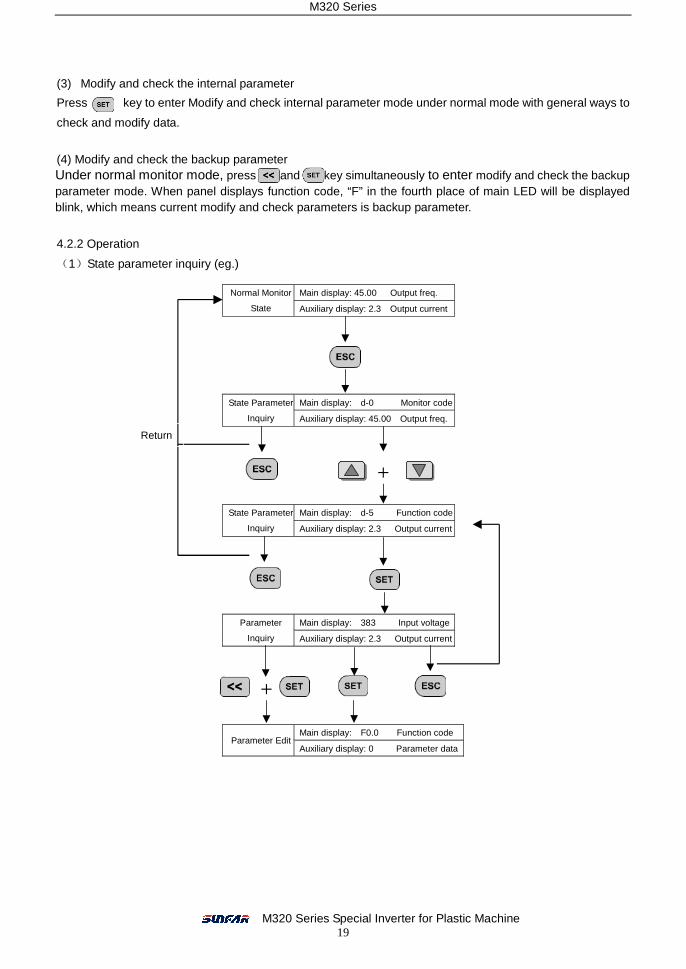
(3) Modify and check the internal parameter
Press key to enter Modify and check internal parameter mode under normal mode with general ways to
check and modify data.
(4) Modify and check the backup parameter Under normal monitor mode, press and key simultaneously to enter modify and check the backup parameter mode. When panel displays function code, “F” in the fourth place of main LED will be displayed blink, which means current modify and check parameters is backup parameter.
4.2.2 Operation
(1)State parameter inquiry (eg.)
Main display: 45.00 Output freq. Normal Monitor
State Auxiliary display: 2.3 Output current
Main display: d-0 Monitor code State Parameter
Inquiry Auxiliary display: 45.00 Output freq.
Main display: d-5 Function code State Parameter
Inquiry Auxiliary display: 2.3 Output current
Main display: 383 Input voltage Parameter
Inquiry Auxiliary display: 2.3 Output current
Main display: F0.0 Function code Parameter Edit
Auxiliary display: 0 Parameter data
+
+
Return
M320 Series
M320 Series Special Inverter for Plastic Machine 20
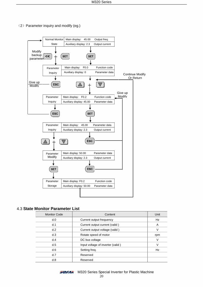
(2)Parameter inquiry and modify (eg.)
4.3 State Monitor Parameter List Monitor Code Content Unit
d.0 Current output frequency Hz
d.1 Current output current (valid ) A
d.2 Current output voltage (valid ) V
d.3 Rotate speed of motor rpm
d.4 DC bus voltage V
d.5 Input voltage of inverter (valid ) V
d.6 Setting freq. Hz
d.7 Reserved
d.8 Reserved
Main display: 45.00 Output freq. Normal Monitor
State Auxiliary display: 2.3 Output current
Main display: F0.0 Function code Parameter
Inquiry Auxiliary display: 0 Parameter data
Main display: F0.2 Function code Parameter
Inquiry Auxiliary display: 45.00 Parameter data
Main display: 45.00 Parameter data Parameter
Inquiry Auxiliary display: 2.3 Output current
Main display: 50.00 Parameter data Parameter Modify Auxiliary display: 2.3 Output current
Main display: F0.2 Function code Parameter
Storage Auxiliary display: 50.00 Parameter data
+
+
+
Modify backup
parameter
Give up Modify
Continue Modify Or Return
Give up Modify
M320 Series
M320 Series Special Inverter for Plastic Machine 21
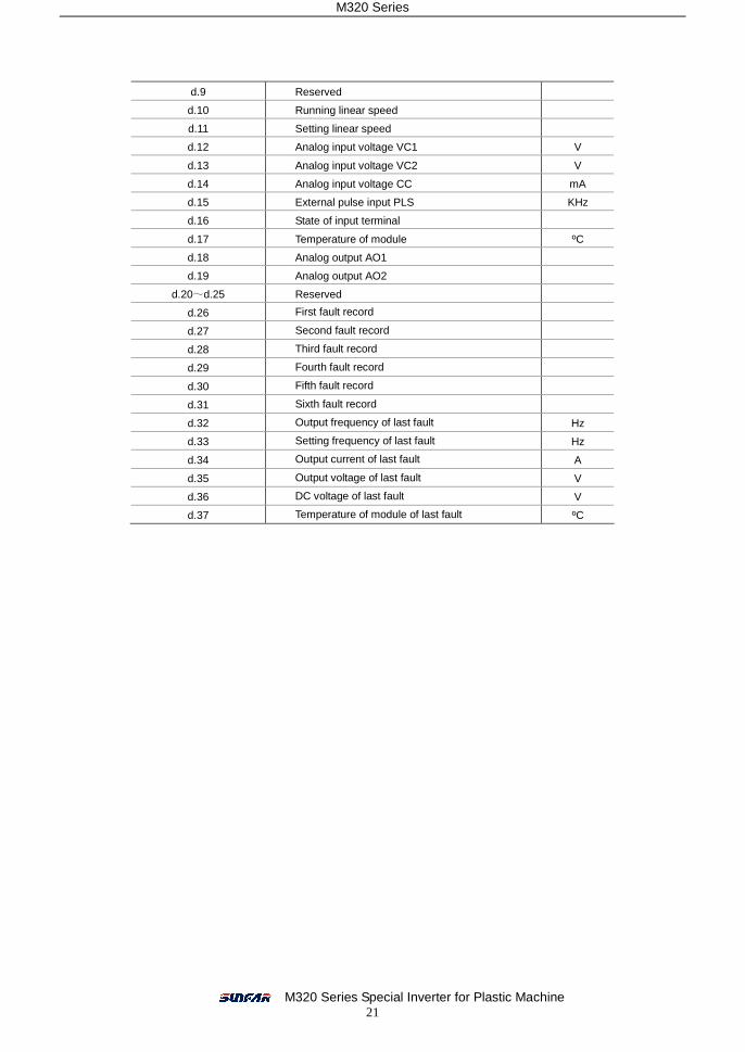
d.9 Reserved
d.10 Running linear speed
d.11 Setting linear speed
d.12 Analog input voltage VC1 V
d.13 Analog input voltage VC2 V
d.14 Analog input voltage CC mA
d.15 External pulse input PLS KHz
d.16 State of input terminal
d.17 Temperature of module ºC
d.18 Analog output AO1
d.19 Analog output AO2
d.20~d.25 Reserved
d.26 First fault record
d.27 Second fault record
d.28 Third fault record
d.29 Fourth fault record
d.30 Fifth fault record
d.31 Sixth fault record
d.32 Output frequency of last fault Hz
d.33 Setting frequency of last fault Hz
d.34 Output current of last fault A
d.35 Output voltage of last fault V
d.36 DC voltage of last fault V
d.37 Temperature of module of last fault ºC
M320 Series
M320 Series Special Inverter for Plastic Machine 22
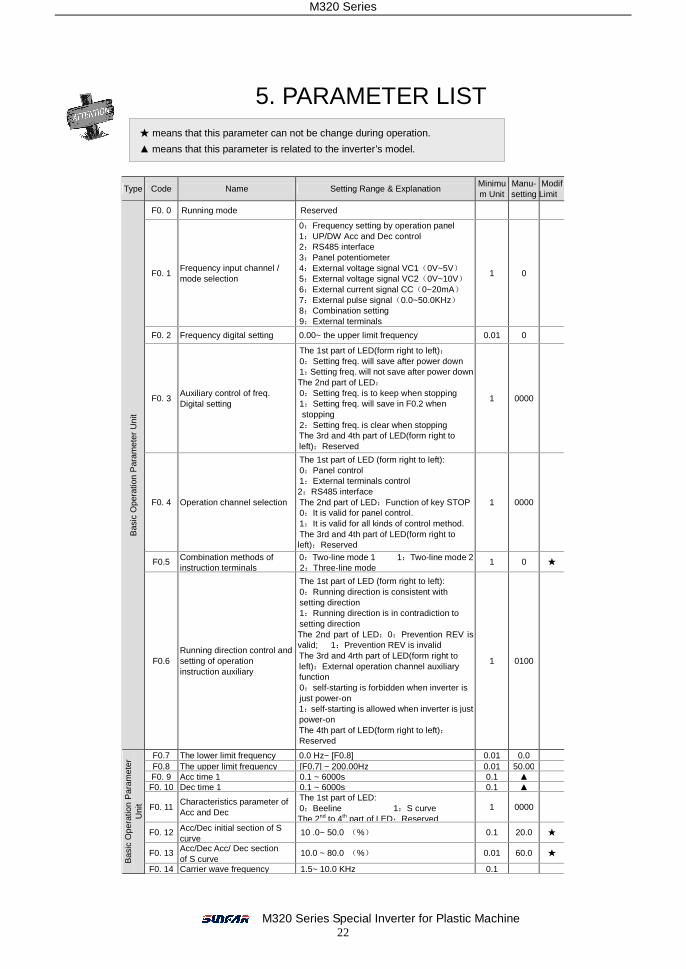
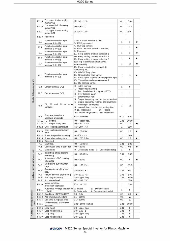
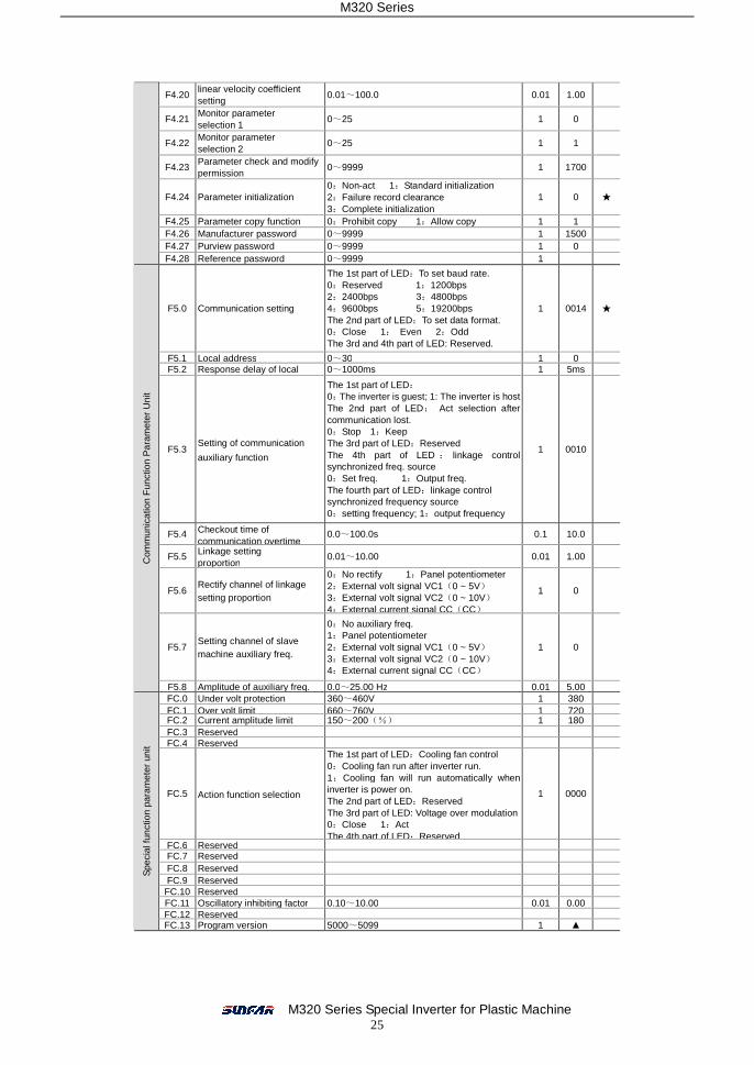
5. PARAMETER LIST
Type Code Name Setting Range & Explanation Minimum Unit
Manu-setting
Modify Limit
F0. 0 Running mode Reserved
F0. 1 Frequency input channel / mode selection
0:Frequency setting by operation panel 1:UP/DW Acc and Dec control 2:RS485 interface 3:Panel potentiometer 4:External voltage signal VC1(0V~5V) 5:External voltage signal VC2(0V~10V) 6:External current signal CC(0~20mA) 7:External pulse signal(0.0~50.0KHz) 8:Combination setting 9:External terminals
1 0
F0. 2 Frequency digital setting 0.00~ the upper limit frequency 0.01 0
F0. 3 Auxiliary control of freq. Digital setting
The 1st part of LED(form right to left): 0:Setting freq. will save after power down 1:Setting freq. will not save after power down The 2nd part of LED: 0:Setting freq. is to keep when stopping 1:Setting freq. will save in F0.2 when stopping 2:Setting freq. is clear when stopping The 3rd and 4th part of LED(form right to left):Reserved
1 0000
F0. 4 Operation channel selection
The 1st part of LED (form right to left): 0:Panel control 1:External terminals control 2:RS485 interface The 2nd part of LED:Function of key STOP 0:It is valid for panel control. 1:It is valid for all kinds of control method. The 3rd and 4th part of LED(form right to left):Reserved
1 0000
F0.5 Combination methods of instruction terminals
0:Two-line mode 1 1:Two-line mode 2 2:Three-line mode
1 0 ★
Bas
ic O
pera
tion
Par
amet
er U
nit
F0.6 Running direction control and setting of operation instruction auxiliary
The 1st part of LED (form right to left): 0:Running direction is consistent with setting direction 1:Running direction is in contradiction to setting direction The 2nd part of LED:0:Prevention REV is valid; 1:Prevention REV is invalid The 3rd and 4rth part of LED(form right to left):External operation channel auxiliary function 0:self-starting is forbidden when inverter is just power-on 1:self-starting is allowed when inverter is just power-on The 4th part of LED(form right to left):Reserved
1 0100
F0.7 The lower limit frequency 0.0 Hz~ [F0.8] 0.01 0.0 F0.8 The upper limit frequency [F0.7] ~ 200.00Hz 0.01 50.00 F0. 9 Acc time 1 0.1 ~ 6000s 0.1 ▲
F0. 10 Dec time 1 0.1 ~ 6000s 0.1 ▲
F0. 11 Characteristics parameter of Acc and Dec
The 1st part of LED: 0:Beeline 1:S curve The 2nd to 4th part of LED:Reserved
1 0000
F0. 12 Acc/Dec initial section of S curve
10 .0~ 50.0 (%) 0.1 20.0 ★
F0. 13 Acc/Dec Acc/ Dec section of S curve
10.0 ~ 80.0 (%) 0.01 60.0 ★
Bas
ic O
pera
tion
Par
amet
er
Uni
t
F0. 14 Carrier wave frequency 1.5~ 10.0 KHz 0.1
means that this parameter can not be change during operati★ on.
▲ means that this parameter is related to the inverter’s model.
M320 Series
M320 Series Special Inverter for Plastic Machine 23
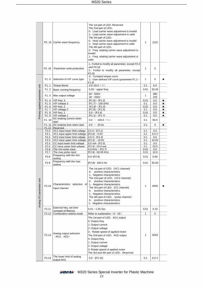
F0. 15 Carrier wave frequency
The 1st part of LED: Reserved The 2nd part of LED: 0:Load carrier wave adjustment is invalid 1:Load carrier wave adjustment is valid The 3rd part of LED: 0:Heat carrier wave adjustment is invalid 1:Heat carrier wave adjustment is valid The 4th part of LED: 0:Freq. relating carrier wave adjustment is invalid 1:Freq. relating carrier wave adjustment is valid
1 1110
F0. 16 Parameter write-protection
1:Forbid to modify all parameter, except F0.2 and F0.18 2:Forbid to modify all parameter, except F0.18
1 0
F1. 0 Selection of V/F curve type 0:Constant torque curve 1:User-defined V/F curve (parameter F1.1~
F1.9) 1 0 ★
F1. 1 Torque Boost 0.0~20.0(%) 0.1 6.0
F1. 2 Basic running frequency 5.00~upper freq. 0.01 50.00
F1. 3 Max output voltage 60~500V 30~250V
1 380 220
F1. 4 V/F freq. 3 [F1.6] ~ [F1.2] 0.01 0.0 ★ F1. 5 V/F voltage 3 [F1.7] ~ 100.0(%) 0.1 0.0 ★ F1. 6 V/F freq. 2 [F1.8] ~ [F1.4] 0.01 0.0 ★ F1. 7 V/F voltage 2 [F1.9] ~ [F1.5] 0.1 0.0 ★ F1. 8 V/F freq. 1 0.0 ~ [F1.6] 0.01 0.0 ★ F1. 9 V/F voltage 1 [F1.1] ~ [F1.7] 0.1 0.0 ★
F1. 10 DC braking current when start
0.0 ~ 100.0(%) 0.1 50.0
F1. 11 DC braking time when start 0.0 ~ 20.0s 0.1 0 ★
Prim
ary
appl
ied
para
met
er u
nit
F1.12 Reserved F2.0 VC1 input lower limit voltage 0.0 V~ [F2.1] 0.1 0.0 F2.1 VC1 input upper limit voltage [F2.0] ~ 5.0V 0.1 5.0 V F2.2 VC2 input lower limit voltage 0.0 V~ [F2.3] 0.1 0.0 F2.3 VC2 input upper limit voltage [F2.2] ~ 10.0V 0.1 10.0V F2.4 CC input lower limit voltage 0.0 mA~ [F2.5] 0.1 4.0 F2.5 CC input upper limit voltage [F2.4] ~20.0 mA 0.1 20.0 F2.6 The min pulse input 0.0 KHz ~ [F2.7] 0.01 0.0 F2.7 The max pulse input [F2.6] ~50.00 KHz 0.01 10.0
F2.8 Frequency with the min setting
0.0~[F2.9] 0.01 0.00
F2.9 Frequency with the max setting
[F2.8]~ 200.0 Hz 0.01 50.00
F2.10 Characteristics selection of
input channel
The 1st part of LED:(VC1 channel) 0: positive characteristics 1:Negative characteristics The 2nd part of LED:(VC2 channel) 0: positive characteristics 1:Negative characteristics The 3rd part of LED:(CC channel) 0: positive characteristics 1:Negative characteristics The 4th part of LED:(pulse channel) 0: positive characteristics 1:Negative characteristics
1 0000 ★
F2.11 External freq. set time constant of filtering
0.01~1.00 Sec 0.01 0.10
F2.12 Combination setting mode Refer to explanation(0~29) 1 0
F2.13 Analog output selection (AO1、AO2)
The 1st part of LED:AO1 output 0: Output freq. 1: Output current 2: Output voltage 3:Rotate speed of applied motor The 2nd part of LED:AO2 output 0: Output freq. 1: Output current 2: Output voltage 3: Rotate speed of applied motor The 3rd and 4th part of LED:Reserved
1 0010
Ana
log
I/O p
aram
eter
uni
t
F2.14 The lower limit of analog output AO1
0.0~[F2.15] 0.1 0.0 V
M320 Series
M320 Series Special Inverter for Plastic Machine 24
F2.15 The upper limit of analog output AO1
[F2.14]~12.0 0.1 10.0V
F2.16 The lower limit of analog output AO2
0.0~[F2.17] 0.1 2.0 V
F2.17 The upper limit of analog output AO2
[F2.16]~12.0 0.1 12.0
F2.18 Reserved
F3.0 Function control of input terminal 1 (0~19)
1 1 ★
F3.1 Function control of input terminal 2 (0~19)
1 2 ★
F3.2 Function control of input terminal 3 (0~19)
1 3 ★
F3.3 Function control of input terminal 4 (0~19)
1 6 ★
F3.4 Function control of input terminal 5 (0~19)
1 13 ★
F3.5 Function control of input terminal 6 (0~19)
0 ~5:Control terminal is idle; 6:FWD jog control; 7:REV jog control; 8:Acc& Dec time selection terminal; 9:Reserved 10:Freq. setting channel selection 1 11:Freq. setting channel selection 2 12:Freq. setting channel selection 3 13: Freq. is controlled gradually to increase (UP) 14:Freq. is controlled gradually to decrease (DW) 15:UP-DW freq. clear 16:Uncontrolled stop control 17:Fault signal of peripheral equipment input 18:Three-line mode running control 19:DC braking control
1 14 ★
F3. 6 Output terminal OC1 1 0
F3. 7 Output terminal OC2 1 1
F3. 8 TA, TB and TC of relay contacts
0:In the running 1:Frequency reaching 2:Freq. level detection signal(FDT) 3:Over-loading alarm 4:External fault halt 5:Output frequency reaches the upper-limit 6:Output frequency reaches the lower-limit 7:Running in zero speed 8:Internal timer reaches the setting time 9~15:Reserved 16:Failure 17:Power range check 18:Reserved
1 16
F3. 9 Frequency reach the checkout amplitude
0.0~20.00 Hz 0. 01 5.00
F3. 10 FDT setting 0.0~upper freq. 0.01 10.00 F3. 11 FDT output delay time 0.0~200.0 Sec 0.1 2.0 ★
F3.12 Over-loading alarm level 50~200(%) 1 110
F3.13 Over-loading alarm delay time
0.0~20.0 Sec 0.1 2.0 ★
F3.14 Power range check setting 0~200(%) 1 100 F3.15 Power check delay time 0.0~200.0 Sec 0.1 2.0 ★
Dig
ital O
/I pa
ram
eter
uni
t
F3.16 Reserved F4.0 Start freq. 0.0~10.00Hz 0.01 1.00 F4.1 Continuous time of start freq. 0.0~20.0s 0.1 0.5 ★ F4.2 Stop mode 0:Decelerate mode 1:Uncontrolled stop 1 0
F4.3 Initial freq. of DC braking when stop
0.0~50.00 Hz 0.01 3.00
F4.4 Action time of DC braking when stop
0.0~20.0s 0.1 0 ★
F4.5 DC braking current when stop
0.0~100(%) 0.1 50.0
F4.6 Running threshold of zero freq.
0.0~100.0 Hz 0.01 0.0
F4.7 Return different of zero freq. 0.0~50.00 Hz 0.01 1.00 F4.8 FWD jog frequency 0.0~upper freq. 0.01 10.00 F4.9 Acc torque level 110~200(%) 1 150 A
uxili
ary
runn
ing
para
met
er u
nit
F4.10 Motor over-lode protection coefficient
50~110(%) 1 110
F4.11 Automatic voltage regulation(AVR)
0:Invalid 1: Dynamic valid 2:Static valid 3:Deceleration invalid
1 0
F4.12 Dead time of FWD& REV 0.0~5.0s 0.1 0.0 ★ F4.13 Acc time 2/Jog Acc time 0.1~6000s 0.1 ▲ F4.14 Dec time 2/Jog Dec time 0.1~6000s 0.1 ▲
F4.15 Modified rated of UP/ DW terminals
0.01~100.0 Hz/Sec 0.01 10.00
F4.16 Leap freq 1 0.0~upper freq. 0.01 0 F4.17 Leap freq scope. 1 0.0~5.00 Hz 0.01 0 F4.18 Leap freq 2 0.0~upper freq. 0.01 0
Aux
iliar
y ru
nnin
g pa
ram
eter
un
it
F4.19 Leap freq scope 2 0.0~5.00 Hz 0.01 0
M320 Series
M320 Series Special Inverter for Plastic Machine 25
F4.20 linear velocity coefficient setting
0.01~100.0 0.01 1.00
F4.21 Monitor parameter selection 1
0~25 1 0
F4.22 Monitor parameter selection 2
0~25 1 1
F4.23 Parameter check and modify permission
0~9999 1 1700
F4.24 Parameter initialization 0:Non-act 1:Standard initialization 2:Failure record clearance 3:Complete initialization
1 0 ★
F4.25 Parameter copy function 0:Prohibit copy 1:Allow copy 1 1 F4.26 Manufacturer password 0~9999 1 1500 F4.27 Purview password 0~9999 1 0 F4.28 Reference password 0~9999 1
F5.0 Communication setting
The 1st part of LED:To set baud rate. 0:Reserved 1:1200bps 2:2400bps 3:4800bps 4:9600bps 5:19200bps The 2nd part of LED:To set data format. 0:Close 1: Even 2:Odd The 3rd and 4th part of LED: Reserved.
1 0014 ★
F5.1 Local address 0~30 1 0 F5.2 Response delay of local 0~1000ms 1 5ms
F5.3 Setting of communication
auxiliary function
The 1st part of LED: 0:The inverter is guest; 1: The inverter is host The 2nd part of LED: Act selection after communication lost. 0:Stop 1:Keep The 3rd part of LED:Reserved The 4th part of LED : linkage control synchronized freq. source 0:Set freq. 1:Output freq. The fourth part of LED:linkage control synchronized frequency source 0:setting frequency; 1:output frequency
1 0010
F5.4 Checkout time of communication overtime
0.0~100.0s 0.1 10.0
F5.5 Linkage setting proportion
0.01~10.00 0.01 1.00
F5.6 Rectify channel of linkage setting proportion
0:No rectify 1:Panel potentiometer 2:External volt signal VC1(0 ~ 5V) 3:External volt signal VC2(0 ~ 10V) 4:External current signal CC(CC)
1 0
F5.7 Setting channel of slave machine auxiliary freq.
0:No auxiliary freq. 1:Panel potentiometer 2:External volt signal VC1(0 ~ 5V) 3:External volt signal VC2(0 ~ 10V) 4:External current signal CC(CC)
1 0
Com
mun
icat
ion
Fun
ctio
n P
aram
eter
Uni
t
F5.8 Amplitude of auxiliary freq. 0.0~25.00 Hz 0.01 5.00 FC.0 Under volt protection 360~460V 1 380 FC.1 Over volt limit 660~760V 1 720 FC.2 Current amplitude limit 150~200(%) 1 180 FC.3 Reserved FC.4 Reserved
FC.5 Action function selection
The 1st part of LED:Cooling fan control 0:Cooling fan run after inverter run. 1:Cooling fan will run automatically when inverter is power on. The 2nd part of LED:Reserved The 3rd part of LED: Voltage over modulation 0:Close 1:Act The 4th part of LED:Reserved
1 0000
FC.6 Reserved FC.7 Reserved FC.8 Reserved FC.9 Reserved
FC.10 Reserved FC.11 Oscillatory inhibiting factor 0.10~10.00 0.01 0.00 FC.12 Reserved
Spe
cial
func
tion
para
met
er u
nit
FC.13 Program version 5000~5099 1 ▲
M320 Series
M320 Series Special Inverter for Plastic Machine 26
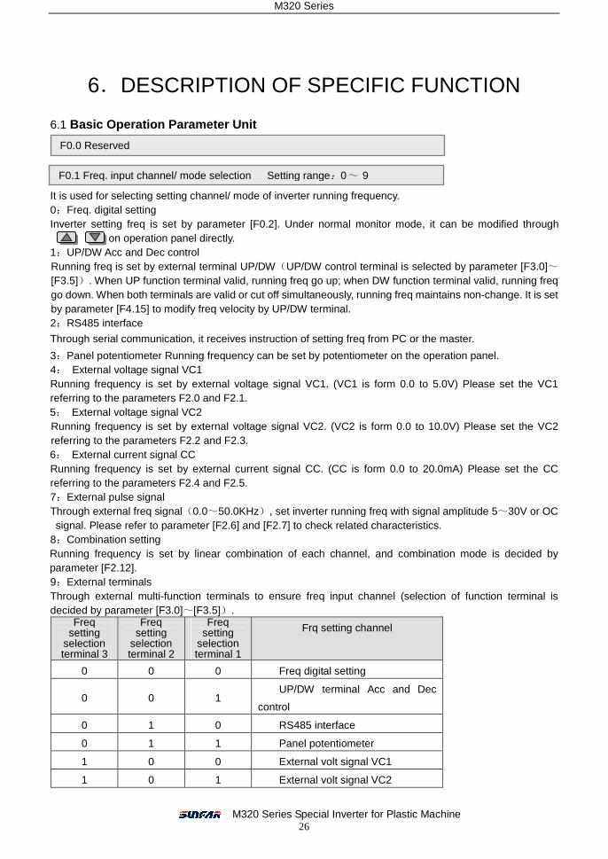
6.DESCRIPTION OF SPECIFIC FUNCTION 6.1 Basic Operation Parameter Unit
It is used for selecting setting channel/ mode of inverter running frequency. 0:Freq. digital setting Inverter setting freq is set by parameter [F0.2]. Under normal monitor mode, it can be modified through
on operation panel directly. 1:UP/DW Acc and Dec control Running freq is set by external terminal UP/DW(UP/DW control terminal is selected by parameter [F3.0]~[F3.5]). When UP function terminal valid, running freq go up; when DW function terminal valid, running freq go down. When both terminals are valid or cut off simultaneously, running freq maintains non-change. It is set by parameter [F4.15] to modify freq velocity by UP/DW terminal. 2:RS485 interface
Through serial communication, it receives instruction of setting freq from PC or the master.
3:Panel potentiometer Running frequency can be set by potentiometer on the operation panel. 4: External voltage signal VC1 Running frequency is set by external voltage signal VC1. (VC1 is form 0.0 to 5.0V) Please set the VC1 referring to the parameters F2.0 and F2.1. 5: External voltage signal VC2 Running frequency is set by external voltage signal VC2. (VC2 is form 0.0 to 10.0V) Please set the VC2 referring to the parameters F2.2 and F2.3. 6: External current signal CC Running frequency is set by external current signal CC. (CC is form 0.0 to 20.0mA) Please set the CC referring to the parameters F2.4 and F2.5. 7:External pulse signal Through external freq signal(0.0~50.0KHz), set inverter running freq with signal amplitude 5~30V or OC signal. Please refer to parameter [F2.6] and [F2.7] to check related characteristics.
8:Combination setting Running frequency is set by linear combination of each channel, and combination mode is decided by parameter [F2.12]. 9:External terminals Through external multi-function terminals to ensure freq input channel (selection of function terminal is decided by parameter [F3.0]~[F3.5]).
Freq setting
selection terminal 3
Freq setting
selection terminal 2
Freq setting
selection terminal 1
Frq setting channel
0 0 0 Freq digital setting
0 0 1 UP/DW terminal Acc and Dec
control
0 1 0 RS485 interface
0 1 1 Panel potentiometer
1 0 0 External volt signal VC1
1 0 1 External volt signal VC2
F0.1 Freq. input channel/ mode selection Setting range:0~ 9
F0.0 Reserved
M320 Series
M320 Series Special Inverter for Plastic Machine 27
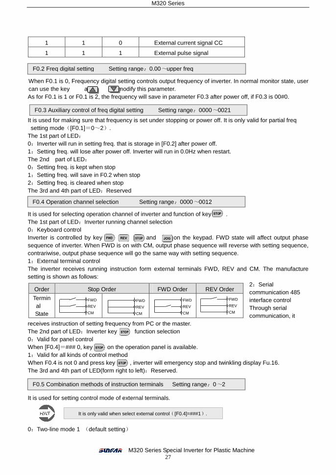
1 1 0 External current signal CC
1 1 1 External pulse signal
When F0.1 is 0, Frequency digital setting controls output frequency of inverter. In normal monitor state, user can use the key and to modify this parameter. As for F0.1 is 1 or F0.1 is 2, the frequency will save in parameter F0.3 after power off, if F0.3 is 00#0.
It is used for making sure that frequency is set under stopping or power off. It is only valid for partial freq setting mode([F0.1]=0~2).
The 1st part of LED: 0:Inverter will run in setting freq. that is storage in [F0.2] after power off. 1:Setting freq. will lose after power off. Inverter will run in 0.0Hz when restart. The 2nd part of LED: 0:Setting freq. is kept when stop 1:Setting freq. will save in F0.2 when stop 2:Setting freq. is cleared when stop The 3rd and 4th part of LED:Reserved
It is used for selecting operation channel of inverter and function of key . The 1st part of LED:Inverter running channel selection 0:Keyboard control Inverter is controlled by key and on the keypad. FWD state will affect output phase sequence of inverter. When FWD is on with CM, output phase sequence will reverse with setting sequence, contrariwise, output phase sequence will go the same way with setting sequence. 1:External terminal control The inverter receives running instruction form external terminals FWD, REV and CM. The manufacture setting is shown as follows:
2:Serial communication 485 interface control Through serial communication, it
receives instruction of setting frequency from PC or the master. The 2nd part of LED:Inverter key function selection 0:Valid for panel control When [F0.4]=### 0, key on the operation panel is available. 1:Valid for all kinds of control method When F0.4 is not 0 and press key , inverter will emergency stop and twinkling display Fu.16. The 3rd and 4th part of LED(form right to left):Reserved.
It is used for setting control mode of external terminals.
0:Two-line mode 1 (default setting)
Order Stop Order FWD Order REV Order
Terminal State
F0.2 Freq digital setting Setting range:0.00~upper freq
F0.3 Auxiliary control of freq digital setting Setting range:0000~0021
F0.4 Operation channel selection Setting range:0000~0012
F0.5 Combination methods of instruction terminals Setting range:0~2
It is only valid when select external control([F0.4]=###1).
FWD
REV
CM
FWD
REV
CM
FWD
REV
CM
FWD
REV
CM
M320 Series
M320 Series Special Inverter for Plastic Machine 28
Order Stop Order FWD Order
REV Order
Terminal State
1:Two-line mode 2
Order Stop Running FWD REV
Terminal State
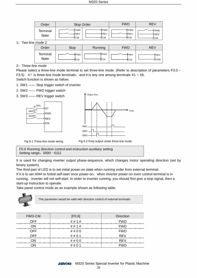
2:Three-line mode Please select a three-line mode terminal to set three-line mode. (Refer to description of parameters F3.0 ~ F3.5) X?is three-line mode terminals,and it is any one among terminals X1 ~ X6. Switch function is shown as follow:
1. SW1 —— Stop trigger switch of inverter
2. SW2 —— FWD trigger switch
3. SW3 —— REV trigger switch
It is used for changing inverter output phase-sequence, which changes motor operating direction (set by binary system). The third part of LED is to set initial power-on state when running order from external terminal. If it is to set #0## to forbid self-start once power-on,when inverter power-on even control terminal is in running,inverter will not self-start. In order to inverter running, you should first give a stop signal, then a start-up instruction to operate. Take panel control mode as an example shown as following table:
FWD-CM [F0.6] Direction
OFF # # 1 # FWD ON # # 1 # FWD OFF # # 0 0 FWD OFF # # 0 1 REV ON # # 0 0 REV ON # # 0 1 FWD
FWD
REV
CM
FWD
REV
CM
FWD
REV
CM
FWD
REV
CM
FWD
CM
FWD
CM
REV
CM
REV
GND
Output freq
Time
SW1
SW2
SW3
Fig 6-1 Three-line mode wiring Fig 6-2 Freq output under three-line mode
F0.6 Running direction control and instruction auxiliary setting Setting range:0000~0111
This parameter would be valid with direction control of external terminals.
SW1
SW2
SW3
X?
FWD
REV
CM

M320 Series
M320 Series Special Inverter for Plastic Machine 29
When real setting freq is below lower freq, inverter runs under lower freq. However, parameter [F4.6] & [F4.7] are priority over this parameter.
It is to define changeable velocity up and down of inverter output freq. Acc time 1: output frequency accelerating from 0.0 Hz to 50.00Hz. Dec time 1: output frequency decelerating from 50.00 Hz to 0.00Hz.
It is to set inverter acc and dec characteristics parameter (set by binary system). The 1st part of LED:It is to set curve type when inverter is accelerating or decelerating shown as fig 6-3. 0: Beeline Inverter output freq increases or decreases based on fixed velocity. For most loads, it may choose this mode. 1: S curve Inverter output freq increases or decreases based on graded velocity. Characteristic of S curve is set by parameter F0.12 and F0.13. This function is for decreasing noise and vibration of acc and dec to reduce load impact when start and stop. If load inertia is over large that cause failure of dec over-volt, it may adjust parameter setting of S dec curve ([F0.12] & [F0.13]). The 2nd- 4th of LED:Reserved
Parameters F0.12 and F0.12 define characteristic parameter of S curve with three sections, shown as fig6-3. Acc/Dec initial section is the process that output freq slope increases gradually form 0. The slope will be fixed with Acc/Dec ascending/decline section. The slope will decrease gradually to 0 in end section. This parameter is to decide power on and off freq of inverter inner power module. The allowable highest and lowest carrier wave freq is different for different power range. Carrier wave freq influences audio-frequency noise and calorific effect mainly. When need no noise for running, it may increase rate of carrier wave freq, but inverter highest load would decrease a little bit. Meantime, interference range to ambience would increase a little. For long motor line situation, it may increase creepage between motor lines. If environmental temperature is too high, motor’s load is too heavy, or any failure caused by above reasons, carrier frequency should be decreased properly to improve heat thermal performance.
It is to set some related characteristics of carrier wave without alteration normally.
F0.7 Upper freq Setting range:0.0 Hz~ [f0.8] F0.8 Upper freq Setting range:[F0.7]~200.00 Hz
F0.9 Acc time 1 Setting range:0.1~6000 Sec F0.10 Dec time 1 Setting range:0.1~6000 Sec
F0.11 Characteristics parameter of Acc and Dec Setting range:0000~0001
S curve
Beeline
Time(Sec/min)
Output freq(Hz)
[F0.12] [F0.13]
Fig 6-3 Acc & dec curve
F0.12 Acc/Dec initial proportion of S curve Setting range:10.0~50.0(%) F0.13 Acc/Dec ascending/decline proportion of S curve Setting range:10.0~80.0(%)
F0.14 Carrier wave freq Setting range:1.5~10.0 KHz
F0.15 Carrier wave characteristics Setting range:0000~1110

M320 Series
M320 Series Special Inverter for Plastic Machine 30
The 1st part of LED:Reserved The 2nd part of LED:Load related carrier wave auto-adjustment. It is valid when load current is high. It will automatically reduce carrier freq to ensure safe operation. 0:Close 1:Act The 3rd part of LED:Heat related carrier wave adjustment It is valid when environmental temperature is high. Inverter will automatically reduce carrier wave freq. 0:Close 1:Act The 4th part of LED:Freq related carrier wave adjustment When it is valid, inverter will automatically reduce carrier freq in low-freq running. 0:Close 1:Act Note:When inverter adjusts carrier freq automatically, running noise will increase a little.
It is used for preventing data error modify. 1:Forbid to modify all parameters, except F0.2 and F0.16. 2:Forbid to modify all parameters, except F0.16. Other data: all can be modified.
6.2 Primary Applied Parameter Unit
For different load, it is used for setting corresponding curve of inverter output volt and freq shown as fig 6-4: 0:Constant torque curve It is used for constant torque load, output volt and output freq as beeline. 1:Uuser-defined V/F curve For this mode, it can be set through function code [F1.1]~[F1.9] freely for required V/F curve.
It is used for improving low-freq torque characteristics. In low-freq running, it will make boost compensation for inverter output volt shown as Fig.6-5.
F0.16 Parameter write-protect Setting range:1,2
When running, some parameters cannot be modified. At this time, if try to modify these parameters, inverter will display “— —”, please turn off inverter before modify those parameters.
Parameter unit [F1.0]~[F1.9] is to set V/F curve under V/F control mode. Based on load type, it may choose to set V/F curve type freely(parameter [F1.0]). In order to settle low freq torque shortage of V/F control mode, set torque compensation would boost output torque. Actually, it boosts inverter output volt so as to increase inverter output current. Toque exaltation is set by parameter [F1.1]]. Parameter [F1.4]-[1.9] is to define output curve set of V/F curve.
F1.0 V/F curve type Setting range:0~1
Volt
Constant torque curve
[F1.3]
[F1.2] Basic running freq
Freq
Max output volt
Fig 6-4 V/F curve
F1.1 Torque Boost (output voltage at 0 Hz) Setting range:0.0~20.0(%)
100
[F1.1] × [F1.3] Boost Volt
M320 Series
M320 Series Special Inverter for Plastic Machine 31
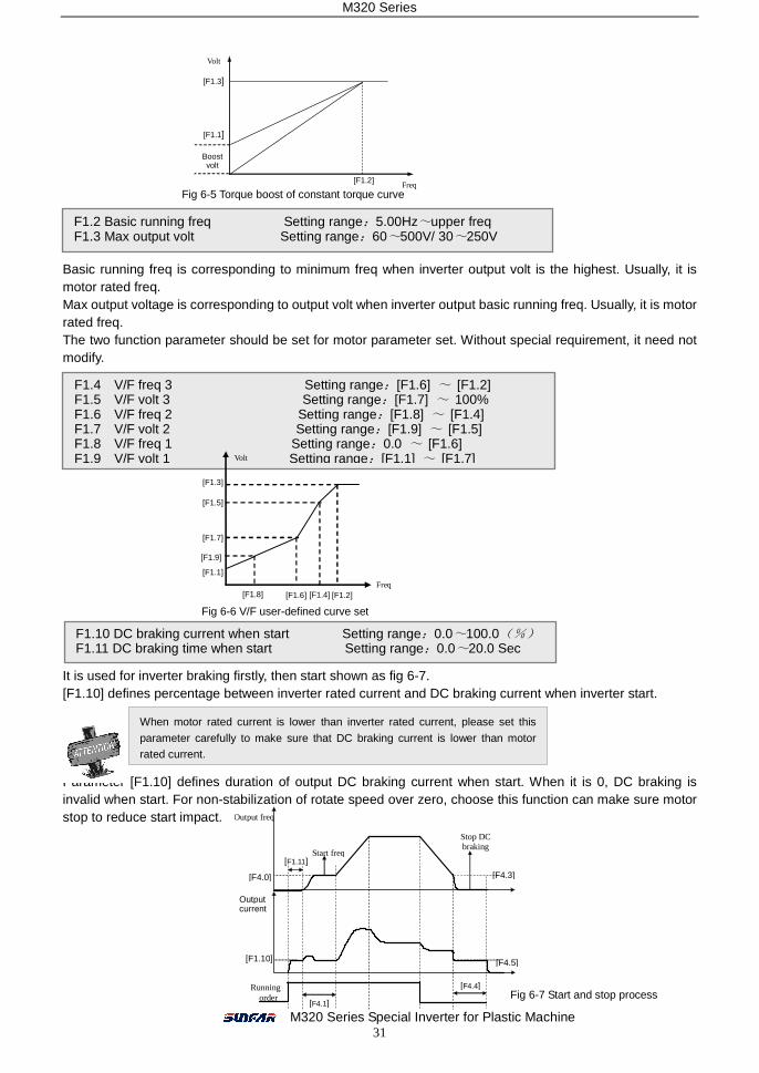
Basic running freq is corresponding to minimum freq when inverter output volt is the highest. Usually, it is motor rated freq. Max output voltage is corresponding to output volt when inverter output basic running freq. Usually, it is motor rated freq. The two function parameter should be set for motor parameter set. Without special requirement, it need not modify.
This parameter is used for required V/F curve flexibly shown as fig 6-6:
It is used for inverter braking firstly, then start shown as fig 6-7. [F1.10] defines percentage between inverter rated current and DC braking current when inverter start.
Parameter [F1.10] defines duration of output DC braking current when start. When it is 0, DC braking is invalid when start. For non-stabilization of rotate speed over zero, choose this function can make sure motor stop to reduce start impact.
Fig 6-5 Torque boost of constant torque curve
F1.2 Basic running freq Setting range:5.00Hz~upper freq F1.3 Max output volt Setting range:60~500V/ 30~250V
F1.4 V/F freq 3 Setting range:[F1.6] ~ [F1.2] F1.5 V/F volt 3 Setting range:[F1.7] ~ 100% F1.6 V/F freq 2 Setting range:[F1.8] ~ [F1.4] F1.7 V/F volt 2 Setting range:[F1.9] ~ [F1.5] F1.8 V/F freq 1 Setting range:0.0 ~ [F1.6] F1.9 V/F volt 1 Setting range:[F1.1] ~ [F1.7]
Fig 6-6 V/F user-defined curve set
F1.10 DC braking current when start Setting range:0.0~100.0(%) F1.11 DC braking time when start Setting range:0.0~20.0 Sec
When motor rated current is lower than inverter rated current, please set this
parameter carefully to make sure that DC braking current is lower than motor rated current.
Fig 6-7 Start and stop process
Freq
Volt
[F1.5]
[F1.7]
[F1.9]
[F1.1]
[F1.8] [F1.6] [F1.4]
[F1.3]
[F1.2]
Volt
[F1.3]
[F1.2]
Freq
[F1.1]
Boost volt
Output freq
Running order
Start freq
[F4.3]
Stop DC braking
[F4.0]
[F1.10]
Output current
[F4.5]
[F4.4]
[F4.1]
[F1.11]
M320 Series
M320 Series Special Inverter for Plastic Machine 32
6.3 Analog Input & Output Parameter Unit
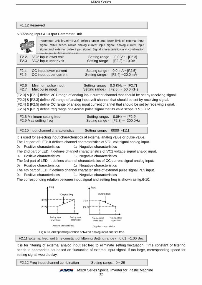
[F2.0] & [F2.1] define VC1 range of analog input current channel that should be set by receiving signal. [F2.2] & [F2.3] define VC range of analog input volt channel that should be set by receiving signal. [F2.4] & [F2.5] define CC range of analog input current channel that should be set by receiving signal. [F2.6] & [F2.7] define freq range of external pulse signal that its valid scope is 5~30V.
定义模拟量输入量或脉冲量与设定频率的对应关系(参见图 6-10)。
It is used for selecting input characteristics of external analog value or pulse value. The 1st part of LED: It defines channel characteristics of VC1 volt signal analog input. 0: Positive characteristics 1:Negative characteristics The 2nd part of LED: It defines channel characteristics of VC2 voltage signal analog input. 0: Positive characteristics 1:Negative characteristics The 3rd part of LED: It defines channel characteristics of CC current signal analog input. 0: Positive characteristics 1:Negative characteristics The 4th part of LED: It defines channel characteristics of external pulse signal PLS input. 0: Positive characteristics 1:Negative characteristics The corresponding relation between input signal and setting freq is shown as fig.6-10.
It is for filtering of external analog input set freq to eliminate setting fluctuation. Time constant of filtering needs to appropriate set based on fluctuation of external input signal. If too large, corresponding speed for setting signal would delay,
F1.12 Reserved
Parameter unit [F2.0]~[F2.7] defines upper and lower limit of external input signal. M320 series allows analog current input signal, analog current input
signal and external pulse input signal. Signal characteristics and combination
can be set by [F2.8]~[F2.12]. F2.2 VC2 input lower volt Setting range: 0.0 V~ [F2.3] F2.3 VC2 input upper volt Setting range: [F2.2]~10.0V
F2.4 CC input lower current Setting range: 0.0 mA~[F2.5] F2.5 CC input upper current Setting range: [F2.4]~20.0 mA
F2.6 Minimum pulse input Setting range: 0.0 KHz~ [F2.7] F2.7 Max pulse input Setting range: [F2.6]~ 50.0 KHz
F2.8 Minimum setting freq Setting range: 0.0Hz~ [F2.9] F2.9 Mas setting freq Setting range: [F2.8]~ 200.0Hz
F2.10 Input channel characteristics Setting range: 0000~1111
Freq
Analog input lower limit
[F2.9]
[F2.8]
Output freq
Analog input upper limit
Positive characteristics
Freq
Analog input lower limit
[F2.9]
[F2.8]
Output freq
Analog input upper limit
Negative characteristics Fig 6-8 Corresponding relation between analog input and set freq
F2.11 External freq. set time constant of filtering Setting range: 0.01~1.00 Sec
F2.12 Freq input channel combination Setting range:0~29
M320 Series
M320 Series Special Inverter for Plastic Machine 33
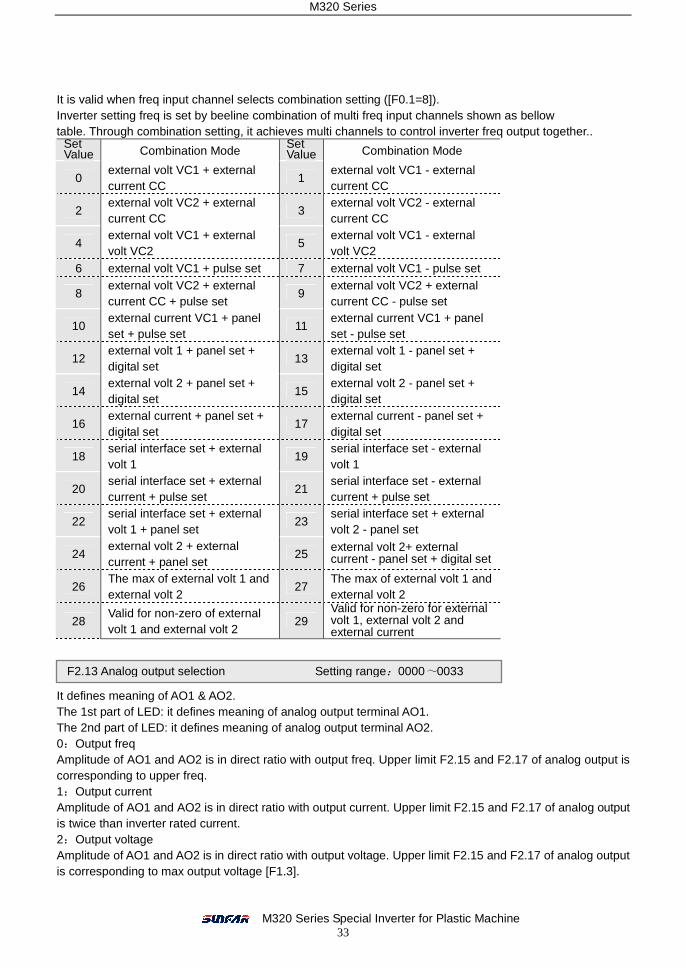
It is valid when freq input channel selects combination setting ([F0.1=8]). Inverter setting freq is set by beeline combination of multi freq input channels shown as bellow table. Through combination setting, it achieves multi channels to control inverter freq output together..
Set Value Combination Mode
Set Value Combination Mode
0 external volt VC1 + external current CC
1 external volt VC1 - external current CC
2 external volt VC2 + external current CC
3 external volt VC2 - external current CC
4 external volt VC1 + external volt VC2
5 external volt VC1 - external volt VC2
6 external volt VC1 + pulse set 7 external volt VC1 - pulse set
8 external volt VC2 + external current CC + pulse set
9 external volt VC2 + external current CC - pulse set
10 external current VC1 + panel set + pulse set
11 external current VC1 + panel set - pulse set
12 external volt 1 + panel set + digital set
13 external volt 1 - panel set + digital set
14 external volt 2 + panel set + digital set
15 external volt 2 - panel set + digital set
16 external current + panel set + digital set
17 external current - panel set + digital set
18 serial interface set + external volt 1
19 serial interface set - external volt 1
20 serial interface set + external current + pulse set
21 serial interface set - external current + pulse set
22 serial interface set + external volt 1 + panel set
23 serial interface set + external volt 2 - panel set
24 external volt 2 + external current + panel set
25 external volt 2+ external current - panel set + digital set
26 The max of external volt 1 and external volt 2
27 The max of external volt 1 and external volt 2
28 Valid for non-zero of external volt 1 and external volt 2
29 Valid for non-zero for external volt 1, external volt 2 and external current
It defines meaning of AO1 & AO2. The 1st part of LED: it defines meaning of analog output terminal AO1. The 2nd part of LED: it defines meaning of analog output terminal AO2. 0:Output freq Amplitude of AO1 and AO2 is in direct ratio with output freq. Upper limit F2.15 and F2.17 of analog output is corresponding to upper freq. 1:Output current Amplitude of AO1 and AO2 is in direct ratio with output current. Upper limit F2.15 and F2.17 of analog output is twice than inverter rated current. 2:Output voltage Amplitude of AO1 and AO2 is in direct ratio with output voltage. Upper limit F2.15 and F2.17 of analog output is corresponding to max output voltage [F1.3].
F2.13 Analog output selection Setting range:0000~0033

M320 Series
M320 Series Special Inverter for Plastic Machine 34
3:Motor rotational speed Amplitude of AO1 and AO2 is in direct ratio with motor rotational speed. Upper limit F2.15 and F2.17 of analog output is corresponding to corresponding rotational speed of upper freq. The 3rd and 4th part of LED: Reserved
Those parameters define max and min value of analog output AO1 and AO2 shown as fig 6-9.
AO1 and AO2 provide voltage signal from 0 to 12V or current signal from 0 to 24 mA. Two kinds of output signal can be selected by switch JP (JP1 and JP2) shown as fig.6-10.
6.4 Digital O/I Parameter Unit 开关量输入端子 X1~X6 功能定义,说明如下:
0~5:Control terminal is idle 6:FWD jog control 7:REV jog control When running order channel selects external terminal valid, this parameters define input terminal of external jog signal. 8:Acc& Dec time selection
F2.14 Lower limit of analog output AO1 Setting range:0.0 V/0.0mA~ [F2.15] F2.15 Upper limit of analog output AO1 Setting range: [F2.14]~12.0 V/24.0mA
F2.16 Lower limit of analog output AO2 Setting range:0.0 V/0.0 mA~ [F2.17] F2.17 Upper limit of analog output AO2 Setting range:[F2.16]~12.0V /24.0mA
Fig 6-9 Output of analog output terminals
JP2: 1-2 shorted:AO1 output voltage signal
2-3 shorted:AO1output current signal
JP3: 1-2 shorted:AO2 output voltage signal
2-3 shorted:AO2 output voltage signal JP2:
Fig 6-10 JP2/JP3 terminal selection
F3.0 Function control of input terminal 1 Setting range:0~19 F3.1 Function control of input terminal 2 Setting range:0~19 F3.2 Function control of input terminal 3 Setting range:0~19 F3.3 Function control of input terminal 4 Setting range:0~19 F3.4 Function control of input terminal 5 Setting range:0~19 F3.5 Function control of input terminal 6 Setting range:0~19
[F2.15]
AO1/AO2
Rated current Output freq Upper freq
Output current Max/rated volt Output volt
Motor speed
1
2 3 4
[F2.17]
[F2.14] [F2.16]
F2.18 Reserved
+5V
+10
V
JP1 JP2
VO
2
VO
1
JP3
CO
1
CO
2
M320 Series
M320 Series Special Inverter for Plastic Machine 35
9:Reserved 10:Freq setting channel selection 1 11:Freq setting channel selection 2 12:Freq setting channel selection 3 When [F0.1] =9, Freq input channel set by terminal selection that inverter freq set channel is controlled by state of the three terminals. Refer to explanation about corresponding parameter [F0.1]. 13: Freq increasing control UP 14: Freq decreasing control DW 15: UP-DW freq clearance When [F0.3] = ##0#, freq set by UP/DW terminal may stay stable. Terminal defined by the parameters can achieve forcible clearance. 16: Free stop control Connect corresponding terminal of this parameters that inverter will lock output and motor stop free running. 17: Peripheral equipment failure signal input If terminal defined by the parameters is close, it means peripheral equipment failure. If so, inverter will lock output and display failure signal FU.16. 18: Three-line mode running control When running order terminal selects three-line mode, external terminal defined by the parameters is inverter stop trigger switch. Refer to explanation about [F0.5]. 19: DC braking control When inverter stops and terminal defined by the parameters is close, it will start DC braking function till this terminal disconnects if output freq is lower than DC braking initial freq. Refer to explanation about [F4.3] ~ [F4.5].
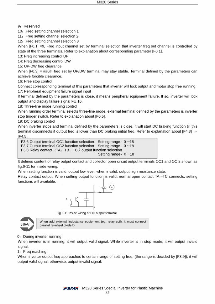
It defines content of relay output contact and collector open circuit output terminals OC1 and OC 2 shown as fig.6-11 for inside wiring. When setting function is valid, output low level; when invalid, output high resistance state. Relay contact output: When setting output function is valid, normal open contact TA –TC connects, setting functions will available.
0:During inverter running When inverter is in running, it will output valid signal. While inverter is in stop mode, it will output invalid signal. 1:Freq reaching When inverter output freq approaches to certain range of setting freq, (the range is decided by [F3.9]), it will output valid signal, otherwise, output invalid signal.
F3.6 Output terminal OC1 function selection Setting range:0~18 F3.7 Output terminal OC2 function selection Setting range:0~18 F3.8 Relay contact(TA、TB、TC)output function selection
Setting range:0~18
Fig 6-11 Inside wiring of OC output terminal
R
1
2
D
When add external inductance equipment (eg. relay coil), it must connect parallel fly-wheel diode D.
M320 Series
M320 Series Special Inverter for Plastic Machine 36
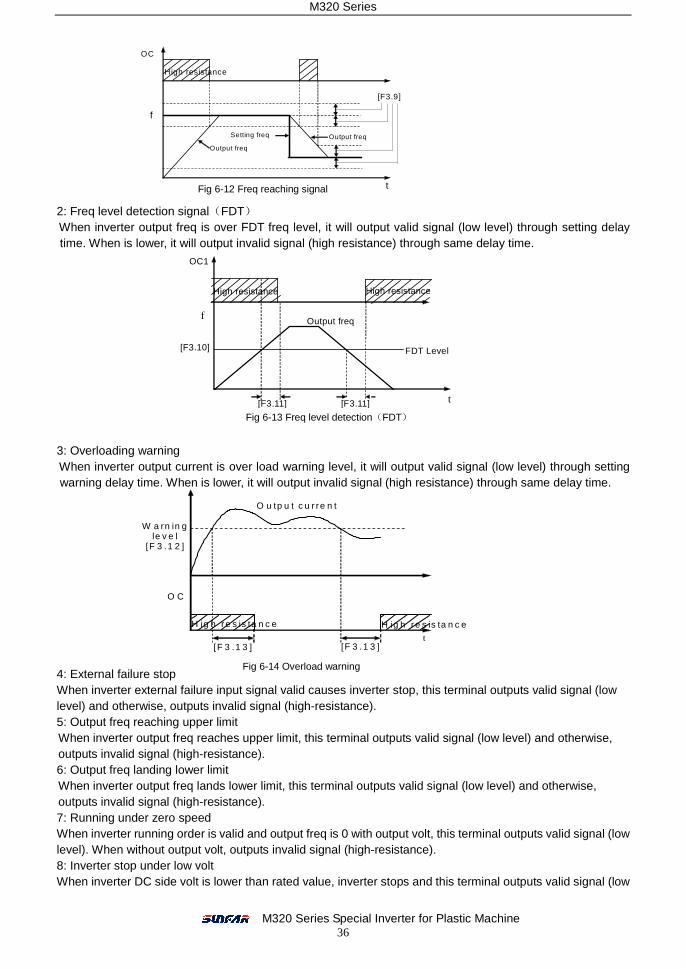
2: Freq level detection signal(FDT) When inverter output freq is over FDT freq level, it will output valid signal (low level) through setting delay time. When is lower, it will output invalid signal (high resistance) through same delay time.
3: Overloading warning When inverter output current is over load warning level, it will output valid signal (low level) through setting warning delay time. When is lower, it will output invalid signal (high resistance) through same delay time.
4: External failure stop When inverter external failure input signal valid causes inverter stop, this terminal outputs valid signal (low level) and otherwise, outputs invalid signal (high-resistance). 5: Output freq reaching upper limit When inverter output freq reaches upper limit, this terminal outputs valid signal (low level) and otherwise, outputs invalid signal (high-resistance). 6: Output freq landing lower limit When inverter output freq lands lower limit, this terminal outputs valid signal (low level) and otherwise, outputs invalid signal (high-resistance). 7: Running under zero speed When inverter running order is valid and output freq is 0 with output volt, this terminal outputs valid signal (low level). When without output volt, outputs invalid signal (high-resistance). 8: Inverter stop under low volt When inverter DC side volt is lower than rated value, inverter stops and this terminal outputs valid signal (low
Fig 6-12 Freq reaching signal
Fig 6-13 Freq level detection(FDT)
Fig 6-14 Overload warning
OC
f
High resistance
[F3.9]
t
Output freq
Setting freq Output freq
High resistance High resistance
Output freq
OC1
t [F3.11]
[F3.10] FDT Level
f
[F3.11]
O u tp u t c u r re n t
t [F 3 .1 3 ]
O C
[F 3 .1 3 ]
W a rn in g le v e l
[F 3 .1 2 ]
H ig h r e s is ta n c e H ig h re s is ta n c e
M320 Series
M320 Series Special Inverter for Plastic Machine 37
level) and otherwise, outputs invalid signal (high-resistance). 9~15: Reserved 16: Inverter failure When inverter failure stops running, it will output valid signal (low level). When normal, it is high-resistance state. 17: Power level detection When inverter real output active power is over setting value (it set by [F3.14] which is relative value of rated power) through certain time, it will output valid signal. 18: Reserved
It is for setting freq reaching checkout amplitude defined by OC output terminal. When inverter output freq is within setting value, selected output terminal outputs valid signal shown as fig. 6-12.
This parameter unit is for setting freq detection level. When output freq is higher than FDT setting value through setting delay time, output terminal will output valid signal shown as fig. 6-13.
This parameter unit is for setting overload warning level and warning delay time. When output freq is higher than setting value [F3.12] through [F3.13] setting delay time, output terminal will output valid signal shown as fig. 6-14.
This parameter unit is for setting active power output detection valve value. When real output power is over this setting value (relative value), output terminal will output valid signal.
6.5 Auxiliary Running Parameter Unit
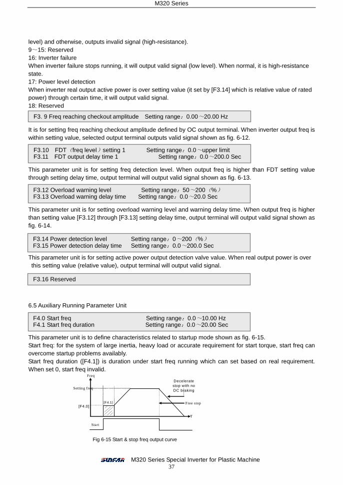
This parameter unit is to define characteristics related to startup mode shown as fig. 6-15. Start freq: for the system of large inertia, heavy load or accurate requirement for start torque, start freq can overcome startup problems availably. Start freq duration ([F4.1]) is duration under start freq running which can set based on real requirement. When set 0, start freq invalid.
F3. 9 Freq reaching checkout amplitude Setting range:0.00~20.00 Hz
F3.10 FDT(freq level)setting 1 Setting range:0.0~upper limit F3.11 FDT output delay time 1 Setting range:0.0~200.0 Sec
F3.12 Overload warning level Setting range:50~200(%) F3.13 Overload warning delay time Setting range:0.0~20.0 Sec
F3.14 Power detection level Setting range:0~200(%) F3.15 Power detection delay time Setting range:0.0~200.0 Sec
T
Freq
Free stop
Decelerate stop with no DC braking Setting freq
[F4.0] [F4.1]
Start
Fig 6-15 Start & stop freq output curve
F4.0 Start freq Setting range:0.0~10.00 Hz F4.1 Start freq duration Setting range:0.0~20.00 Sec
F3.16 Reserved
M320 Series
M320 Series Special Inverter for Plastic Machine 38
0: Decelerating mode Inverter will gradually decrease output freq to 0 following dec time then stop. 1: free stop Inverter will output zero freq and lock output signal when stop. Then, motor stops with free running. If restart motor before complete stop, there will be over-current or over-volt failure protection. Start mode and stop mode is shown as fig 6-15.
This parameter unit is for setting DC braking parameters when stop shown as fig 6-7. When output freq is lower than this setting Parameter, inverter will lock output and start DC braking function during inverter stop process set by DC braking initial freq ([F4.3]). Stop DC braking act time set by parameter [F4.4]. When set 0, stop DC braking functions invalid. Stop DC braking current is inverter rated current percent. When matching motor capacity is lower than inverter capacity, please set DC braking act current value carefully.
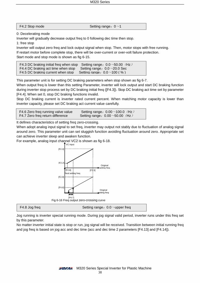
It defines characteristics of setting freq zero-crossing. When adopt analog input signal to set freq, inverter may output not stably due to fluctuation of analog signal around zero. This parameter unit can set sluggish function avoiding fluctuation around zero. Appropriate set can achieve inverter sleep and awaken function. For example, analog input channel VC2 is shown as fig 6-18.
Jog running is inverter special running mode. During jog signal valid period, inverter runs under this freq set by this parameter. No matter inverter initial state is stop or run, jog signal will be received. Transition between initial running freq and jog freq is based on jog acc and dec time (acc and dec time 2 parameters [F4.13] and [F4.14]).
F4.2 Stop mode Setting range:0~1
F4.3 DC braking initial freq when stop Setting range:0.0~50.00(Hz) F4.4 DC braking act time when stop Setting range:0.0~20.0 Sec F4.5 DC braking current when stop Setting range:0.0~100 ( % )
F4.6 Zero freq running valve value Setting range:0.00~100.0(Hz) F4.7 Zero freq return difference Setting range:0.00~50.00(Hz)
Fig 6-16 Freq output zero-crossing curve
F4.8 Jog freq Setting range:0.0~upper freq
[F2.2]
VC input
[F2.9]
Original setting freq
[F2.8]
[F2.3]
Real setting freq
Original setting freq
[F2.9]
[F4.6]
[F4.7]
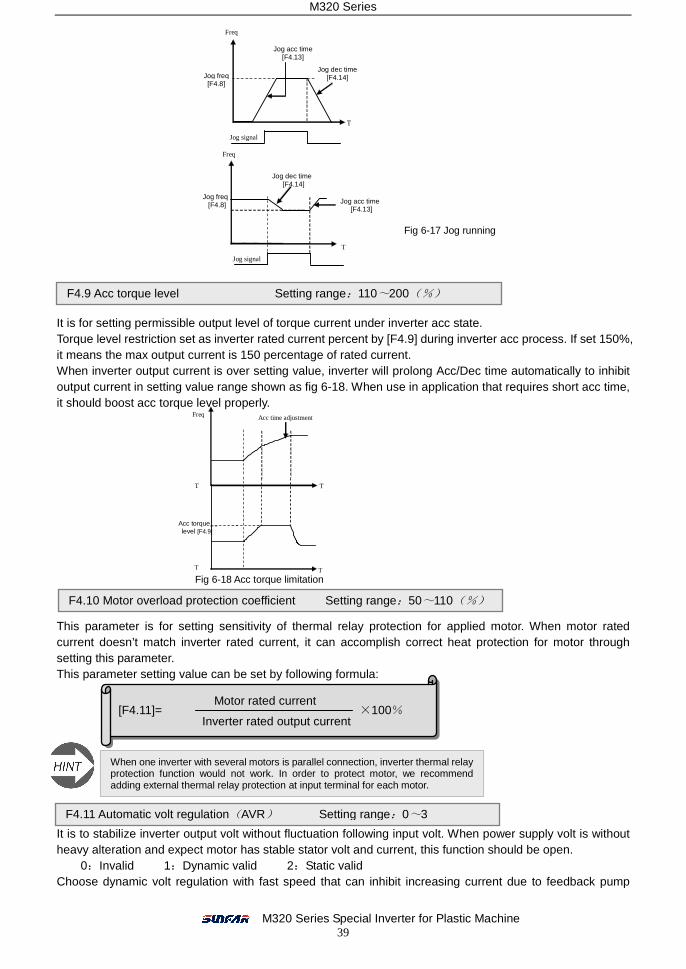
M320 Series
M320 Series Special Inverter for Plastic Machine 39
It is for setting permissible output level of torque current under inverter acc state. Torque level restriction set as inverter rated current percent by [F4.9] during inverter acc process. If set 150%, it means the max output current is 150 percentage of rated current. When inverter output current is over setting value, inverter will prolong Acc/Dec time automatically to inhibit output current in setting value range shown as fig 6-18. When use in application that requires short acc time, it should boost acc torque level properly.
This parameter is for setting sensitivity of thermal relay protection for applied motor. When motor rated current doesn’t match inverter rated current, it can accomplish correct heat protection for motor through setting this parameter. This parameter setting value can be set by following formula:
It is to stabilize inverter output volt without fluctuation following input volt. When power supply volt is without heavy alteration and expect motor has stable stator volt and current, this function should be open.
0:Invalid 1:Dynamic valid 2:Static valid Choose dynamic volt regulation with fast speed that can inhibit increasing current due to feedback pump
T
Jog freq [F4.8]
Freq
Jog signal
Jog dec time [F4.14]
Jog freq [F4.8]
Jog acc time [F4.13]
Jog dec time [F4.14]
Freq
T
Jog signal
Jog acc time [F4.13]
Fig 6-17 Jog running
F4.9 Acc torque level Setting range:110~200(%)
T
Acc torque level [F4.9]
Freq
T
T
T
Acc time adjustment
Fig 6-18 Acc torque limitation
F4.10 Motor overload protection coefficient Setting range:50~110(%)
When one inverter with several motors is parallel connection, inverter thermal relay protection function would not work. In order to protect motor, we recommend adding external thermal relay protection at input terminal for each motor.
F4.11 Automatic volt regulation(AVR) Setting range:0~3
[F4.11]= ×100% Motor rated current
Inverter rated output current

M320 Series
M320 Series Special Inverter for Plastic Machine 40
increasing volt during motor dec process. However, it is easy to cause current resonance. 3: Dec invalid When acc and stable running, automatic volt regulation is valid and dec is invalid.
It is for setting motor waiting time for FWD running to REV running or REV running to FWD running. This function is to overcome reversing current impact caused by mechanical dead zone shown as fig 6-19.
Acc/ dec time selection can be set by external terminal through function parameter unit [F3.0]~[F3.5] to select corresponding control terminal shown as fig 6-20.
Acc/ dec time 2 is jog acc/ dec time as well. Jog freq has the highest priority. In any state, as long as jog instruction input, inverter will transit to jog freq running from setting jog acc and dec time. Refer to explanation about [F4.8].
It defines UP/DW function terminal modification freq velocity. The speed of UP/DW terminal modification setting freq would not be influenced by acc/ dec time.
This parameter unit is for inverter output freq escaping mechanical load resonance point. When inverter output freq passes setting leap freq, upper and lower limit of leap freq scope forms a hysteresis loop taking leap freq as core shown as fig 6-21.
F4.12 FWD& REV dead time Setting range:0.0~5.0 Sec
T
[F4.12]
Output freq
Fig 6-19 Waiting time between FWD and REV
F4.13 Acc time 2/ jog acc time Setting range:0.1~6000 Sec F4.14 Dec time 2/ jog dec time Setting range:0.1~6000 Sec
Freq
T Acc/dec selection terminal
Running order
Acc time 1
Acc time 2
Fig 6-20 External terminal selection of acc/ dec time
F4.15 UP/DW terminal modification velocity Setting range:0.01~100 Hz/Sec
F4.16 Leap freq 1 Setting range:0.0~upper freq F4.17 Leap freq scope 1 Setting range:0.0~ 5.00 Hz F4.18 Leap freq 2 Setting range:0.0~upper freq F4.19 Leap freq scope 2 Setting range:0.0~ 5.00 Hz
Leap freq scope 2
Leap freq scope 1
Leap freq 2
Leap freq 1
Setting freq after adjustment
Fig 6-21 Leap freq output
F4.20 linear velocity coefficient Setting range:0.01~100.0
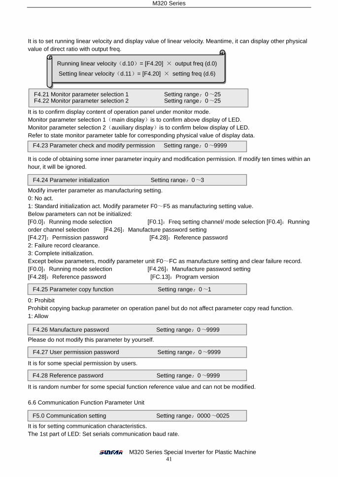
M320 Series
M320 Series Special Inverter for Plastic Machine 41
It is to set running linear velocity and display value of linear velocity. Meantime, it can display other physical value of direct ratio with output freq.
It is to confirm display content of operation panel under monitor mode. Monitor parameter selection 1(main display)is to confirm above display of LED. Monitor parameter selection 2(auxiliary display)is to confirm below display of LED. Refer to state monitor parameter table for corresponding physical value of display data.
It is code of obtaining some inner parameter inquiry and modification permission. If modify ten times within an hour, it will be ignored.
Modify inverter parameter as manufacturing setting. 0: No act. 1: Standard initialization act. Modify parameter F0~F5 as manufacturing setting value. Below parameters can not be initialized: [F0.0]:Running mode selection [F0.1]:Freq setting channel/ mode selection [F0.4]:Running order channel selection [F4.26]:Manufacture password setting [F4.27]:Permission password [F4.28]:Reference password 2: Failure record clearance. 3: Complete initialization. Except below parameters, modify parameter unit F0~FC as manufacture setting and clear failure record. [F0.0]:Running mode selection [F4.26]:Manufacture password setting [F4.28]:Reference password [FC.13]:Program version
0: Prohibit Prohibit copying backup parameter on operation panel but do not affect parameter copy read function. 1: Allow
Please do not modify this parameter by yourself.
It is for some special permission by users.
It is random number for some special function reference value and can not be modified.
6.6 Communication Function Parameter Unit
It is for setting communication characteristics. The 1st part of LED: Set serials communication baud rate.
Running linear velocity(d.10)= [F4.20] × output freq (d.0)
Setting linear velocity(d.11)= [F4.20] × setting freq (d.6)
F4.21 Monitor parameter selection 1 Setting range:0~25 F4.22 Monitor parameter selection 2 Setting range:0~25
F4.23 Parameter check and modify permission Setting range:0~9999
F4.24 Parameter initialization Setting range:0~3
F4.25 Parameter copy function Setting range:0~1
F4.26 Manufacture password Setting range:0~9999
F4.27 User permission password Setting range:0~9999
F4.28 Reference password Setting range:0~9999
F5.0 Communication setting Setting range:0000~0025

M320 Series
M320 Series Special Inverter for Plastic Machine 42
0:Reserved 1:1200 bps 2:2400 bps 3:4800 bps 4: 9600 bps 5:19200 bps When use serials communication, please ensure communication both sides with same baud rate. The 2nd part of LED: Set serials communication data format. 0:Close 1:Even 2:Odd When use serials communication, please ensure communication both sides with same data format. The 3rd and 4th part of LED: Reserved
It is to set this inverter local address when communication and it is only valid when it is slave. During communication process, it only send responding frame of matching data frame for this local address and receive order.
Address 31 is broadcast address. For broadcast data, slave executes order but without feedback responding data. It defines waiting time of sending responding data frame once it receives right signal code.
The 1st part of LED: Inverter setting for master or slave 0: Slave 1: Master When several inverters need linkage synchronous control, one of them should set as master. The 2nd part of LED: Act selection after communication failure 0: Stop 1: Keep present state The 3rd part of LED: Reserved The 4th part of LED: Linkage control synchronous freq source 0: Set freq Master taking this setting freq as freq order sends to slave. 1: Output freq Master taking this output freq as freq order sends to slave.
If there is no correct data signal within this parameter setting time, it’s communication failure. Based on parameter [F5.3], choose stop or keep running.
It is to define the proportion of linkage control, master and slave output freq. When this parameter unit of master inverter without any effect and achieves linkage synchronous control, slave running order and master are synchronous. Slave freq order as follow formula: When [F5.6] = 0, rectify channel of linkage setting freq is invalid. Then: Slave freq order = master freq order × slave setting [F5.5] When [F5.6] = 1~4, rectify channel of linkage setting freq is valid. If rectify channel value is lower limit and rectify coefficient is 0.5; if rectify channel value is upper limit and rectify coefficient is 2.0 and middle liner adjustment, then: Slave freq order = master freq order × slave [F5.5] × rectify coefficient (0.50~2.00) [F5.6] rectify positive channel selection: Rectify channel 1:Panel potentiometer Rectify channel 2:External volt signal VC1(0 ~ 5V) Rectify channel 3:External volt signal VC2(0 ~ 10V) Rectify channel 4:External current signal CC(0 ~ 20mA)
F5.1 Local address Setting range: 0~30
F5.2 Local response time Setting range: 0~1000 ms
F5.3 Communication auxiliary setting Setting range:0000~1011
F5.4 Checkout time for Communication overtime Setting range:0.0~100.0
F5.5 Linkage setting proportion Setting range:0.01~10.00 F5.6 Rectify channel of linkage setting proportion Setting range:0~4

M320 Series
M320 Series Special Inverter for Plastic Machine 43
It is to select setting source of master auxiliary freq and adjustment amplitude of auxiliary freq.
When input value of auxiliary freq setting channel is middle value as 0, slave inverter real output freq = master order freq × linkage proportion + auxiliary freq ( linkage proportion is set by parameter [F5.5] and [F5.6]).
6.7 Special Function Parameter Unit
It is to set inverter DC lower volt besides when normal running. For most occasions, it may decrease under volt protection level a little to make sure inverter normal running. Note: If power supply volt is too low, motor output torque may decrease. For constant power load and constant torque load, it may increase inverter output current if power volt is too low so as to decrease inverter running reliability.
It is to set valve value of volt losing speed protection during motor decreasing speed process. When inverter inner DC pump increasing volt besides is over this parameter setting value during decreasing, it would prolong decreasing time shown as fig 6-23.
It is to set inverter allowable output max current and shows as inverter rated current percent. No matter the running state ( dec, acc or stable running), inverter output current is over this parameter value, inverter will adjust output freq to limit current within regular range.
F5.7 Slave auxiliary freq setting channel Setting range:0~4 F5.8 Auxiliary freq amplitude Setting range:0.0~25.00 Hz
FC.0 Under volt protection Setting range: 360V~460V
FC.1 Over volt limitation act level Setting range:660V~760V
[FC.1]
Freq
Time
Time
Decreasing time adjustment
DC volt
FC.2 Current amplitude limit Setting range:150~200%
FC.3 Reserved FC.4 Reserved
Auxiliary freq
[F5.8]
----[F5.8] 0 Setting
channel input Fig 6-22 Adjustment amplitude of auxiliary freq
Fig 6-23 Volt losing speed protection during decreasing speed

M320 Series
M320 Series Special Inverter for Plastic Machine 44
The 1st part of LED: Cooling fan control 0: Cooling fan runs after inverter running Fan stops when stop. When check temperature is above 40 degree, fan runs automatically. 1: Cooling fan runs once inverter power on. It is no relation with inverter running state. The 2nd part of LED: Reserved The 3rd part of LED: Over volt adjustment 0: Close 1: Act
Inverter control software version only can be read.
FC.5 Function act selection Setting range:0000~0101
FC.6~FC.10 Reserved
FC.12 Reserved
FC.13 Program version Setting range:5000~5099
FC.11 Oscillatory inhibiting factor Setting range:0.0~10.00
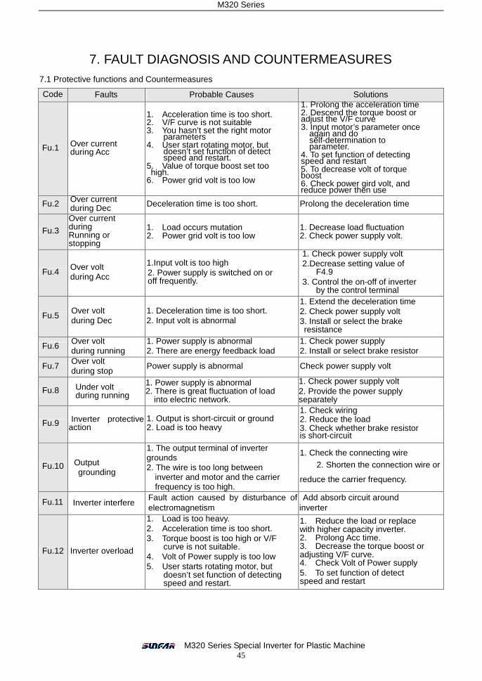
M320 Series
M320 Series Special Inverter for Plastic Machine 45
7. FAULT DIAGNOSIS AND COUNTERMEASURES 7.1 Protective functions and Countermeasures
Code Faults Probable Causes Solutions
Fu.1 Over current during Acc
1. Acceleration time is too short. 2. V/F curve is not suitable 3. You hasn’t set the right motor
parameters 4. User start rotating motor, but
doesn’t set function of detect speed and restart.
5. Value of torque boost set too high. 6. Power grid volt is too low
1. Prolong the acceleration time 2. Descend the torque boost or adjust the V/F curve 3. Input motor’s parameter once
again and do self-determination to parameter.
4. To set function of detecting speed and restart 5. To decrease volt of torque boost 6. Check power gird volt, and reduce power then use
Fu.2 Over current during Dec Deceleration time is too short. Prolong the deceleration time
Fu.3
Over current during Running or stopping
1. Load occurs mutation 2. Power grid volt is too low
1. Decrease load fluctuation 2. Check power supply volt.
Fu.4 Over volt during Acc
1.Input volt is too high 2. Power supply is switched on or off frequently.
1. Check power supply volt 2.Decrease setting value of
F4.9 3. Control the on-off of inverter
by the control terminal
Fu.5 Over volt during Dec
1. Deceleration time is too short. 2. Input volt is abnormal
1. Extend the deceleration time 2. Check power supply volt 3. Install or select the brake resistance
Fu.6 Over volt during running
1. Power supply is abnormal 2. There are energy feedback load
1. Check power supply 2. Install or select brake resistor
Fu.7 Over volt during stop
Power supply is abnormal Check power supply volt
Fu.8 Under volt during running
1. Power supply is abnormal 2. There is great fluctuation of load
into electric network.
1. Check power supply volt 2. Provide the power supply separately
Fu.9 Inverter protective action
1. Output is short-circuit or ground 2. Load is too heavy
1. Check wiring 2. Reduce the load 3. Check whether brake resistor is short-circuit
Fu.10 Output grounding
1. The output terminal of inverter grounds 2. The wire is too long between
inverter and motor and the carrier frequency is too high.
1. Check the connecting wire 2. Shorten the connection wire or
reduce the carrier frequency.
Fu.11 Inverter interfere Fault action caused by disturbance of electromagnetism
Add absorb circuit around inverter
Fu.12 Inverter overload
1. Load is too heavy. 2. Acceleration time is too short. 3. Torque boost is too high or V/F
curve is not suitable. 4. Volt of Power supply is too low 5. User starts rotating motor, but
doesn’t set function of detecting speed and restart.
1. Reduce the load or replace with higher capacity inverter. 2. Prolong Acc time. 3. Decrease the torque boost or adjusting V/F curve. 4. Check Volt of Power supply 5. To set function of detect speed and restart

M320 Series
M320 Series Special Inverter for Plastic Machine 46
Fu.13 Motor overload
1. Load is too heavy. 2. Acceleration time is too short. 3. The setting of protection factor is too small 4. Torque boost is too high or V/F curve
is not suitable.
1. Reduce the load 2. Prolong Acc time 3. Increase the overloading protection factor of motor [F4.10]) 4. Decrease torque boost volt and adjust V/F curve.
Fu.14 Inverter overheat
1. Wind hole is blocked 2. Environmental temperature is too high 3. Fan is damaged
1. Clear air duct or improve the air condition. 2. Improve ventilation condition or decrease carrier frequency. 3. Replace fan.
Fu.15 Reserved
Fu.16 External equipment failure
There is signal input on the peripheral. Equipment fault input terminal of Inverter
Check the signal source and pertinent equipments.
Fu.17 Reserved Fu.18 Reserved Fu.19 Reserved
Fu.20 Current checking error
1. The current detecting equipment or circuit is damaged
2. Auxiliary power supply has problem
Contract Us
Fu.21 Temperature sensor fault
1. Signal line of temperature is poor contact
2. Temperature sensor is damage.
1. Check jack 2. Contract Us
Fu.22- Fu.39
Reserved
Fu.40 Inner data of
storage is wrong.
Read and write errors of the control parameter Contract Us
7.2 Fault record inquiry
M320 series inverter records the last six fault codes and the output parameters of last fault. This information
is aid in looking up the fault causes. Fault information and State monitor parameters are stored uniformly, so
please refer to the operation way to look up the information.
7.3 Reset
When inverter occurs fault, you can reset the inverter to resume the normal running by any way as follows:
Monitor Item Contents Monitor Item Contents
d-26 First fault record d-32 Output frequency of last fault d-27 Second fault record d-33 Setting frequency of last fault d-28 Third fault record d-34 Output current of last fault d-29 Fourth fault record d-35 Output volt of last fault
d-30 Fifth fault record d-36 DC volt of last fault
d-31 Sixth fault record d-37 Module temperature of last

M320 Series
M320 Series Special Inverter for Plastic Machine 47
I. External reset input-terminal RST and GND terminal are closed, and then off.
II. While the fault code is displayed, press key.
III. It will send fault reset instrument by RS485 interface.
IV. Turn the power source off.
⑴ Be sure to check the fault cause and exclude it before reset, otherwise, which may lead to inverter, permanent damaged.
⑵ If inverter can not be reset or occur the fault again after reset, please find out the reason. Continuous reset will damage inverter.
⑶ Overload or overheat protective action should delay 5 minutes to reset.
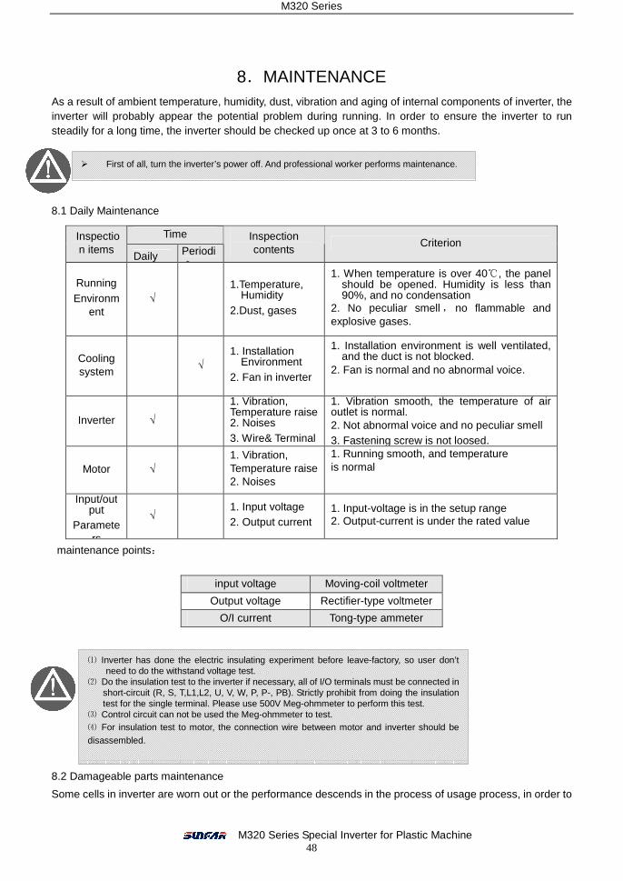
M320 Series
M320 Series Special Inverter for Plastic Machine 48
8.MAINTENANCE As a result of ambient temperature, humidity, dust, vibration and aging of internal components of inverter, the inverter will probably appear the potential problem during running. In order to ensure the inverter to run steadily for a long time, the inverter should be checked up once at 3 to 6 months.
8.1 Daily Maintenance
maintenance points:
8.2 Damageable parts maintenance
Some cells in inverter are worn out or the performance descends in the process of usage process, in order to
Time Inspection items
Daily Periodic
Inspection contents
Criterion
Running Environm
ent √
1.Temperature, Humidity
2.Dust, gases
1. When temperature is over 40 , the panel ℃should be opened. Humidity is less than 90%, and no condensation
2. No peculiar smell , no flammable and explosive gases.
Cooling system
√ 1. Installation
Environment 2. Fan in inverter
1. Installation environment is well ventilated, and the duct is not blocked.
2. Fan is normal and no abnormal voice.
Inverter √
1. Vibration, Temperature raise 2. Noises 3. Wire& Terminal
1. Vibration smooth, the temperature of air outlet is normal. 2. Not abnormal voice and no peculiar smell 3. Fastening screw is not loosed.
Motor √ 1. Vibration, Temperature raise 2. Noises
1. Running smooth, and temperature is normal
Input/output
Parameters
√ 1. Input voltage 2. Output current
1. Input-voltage is in the setup range 2. Output-current is under the rated value
input voltage Moving-coil voltmeter
Output voltage Rectifier-type voltmeter
O/I current Tong-type ammeter
� First of all, turn the inverter’s power off. And professional worker performs maintenance.
⑴ Inverter has done the electric insulating experiment before leave-factory, so user don’t need to do the withstand voltage test.
⑵ Do the insulation test to the inverter if necessary, all of I/O terminals must be connected in short-circuit (R, S, T,L1,L2, U, V, W, P, P-, PB). Strictly prohibit from doing the insulation test for the single terminal. Please use 500V Meg-ohmmeter to perform this test.
⑶ Control circuit can not be used the Meg-ohmmeter to test. ⑷ For insulation test to motor, the connection wire between motor and inverter should be disassembled.
M320 Series
M320 Series Special Inverter for Plastic Machine 49
ensure the stable running of inverter, so the inverter needs to do the preventative maintenance or replace the part if necessary.
Filter capacitor⑴
Pulse current in main circuit will take effect on the performance of aluminum electrolytic filter capacitor, and the degree of effect has relation with the ambient temperature and usage condition. In normal condition, the electrolytic capacitor of inverter should be replaced at 4 to 5 years.
When the electrolytic capacitor leaks out, safety valve falls out or main block of capacitor expands, the
corresponding parts should be replaced immediately.
Cooling fan⑵ The lifetime of all the cooling fans in the inverter is about 15000 hours (that inverter is used continuously about two years). If the fan happens to abnormal noise or vibration, it should be replaced immediately.
8.3 Storage
If the inverter don’t used for a long time, please notice the following items:
(1) To avoid storing the inverter at the environment with high-temperature,humidity, vibration or metal dust, and ensure the well ventilation.
(2) If the inverter is not used for a long time, it should be energized to resume the capability of electrolyte capacitor once at 2 years,at the same time, check the functions of inverter. When the inverter is electrified, its voltage should be increased by an autotransformer step by step and the time should not be less than 5 hours.
8.4 After sale services
Guarantee time of this inverter is 12 months (From the day of purchase). In guarantee Time, if the inverter occurs fault or be damaged in normal usage, our company will provide the free repair service or replacement.
In guarantee time, if the faults are caused by the following cases, certain service cost would be charged. ① Malfunction caused by not following the operation manual or over the standard specification;
Malfunction caused by repair or refitting by oneself without grant. ② Malfunction caused by the bad③ -storage. Malfunction due to application of inverter for abnor④ mal functional needs. Damage caused by the fire, salt⑤ -corrode, gas-corrode, earthquake, storm, flood, thunder, voltage
abnormal or other force majored.
Even if over guarantee time, our company will provide the paid service forever.
� If inverter is not used for a long time, the performance of internal filter capacitor will
descend.
Guarantee scale is just the master of inverter.
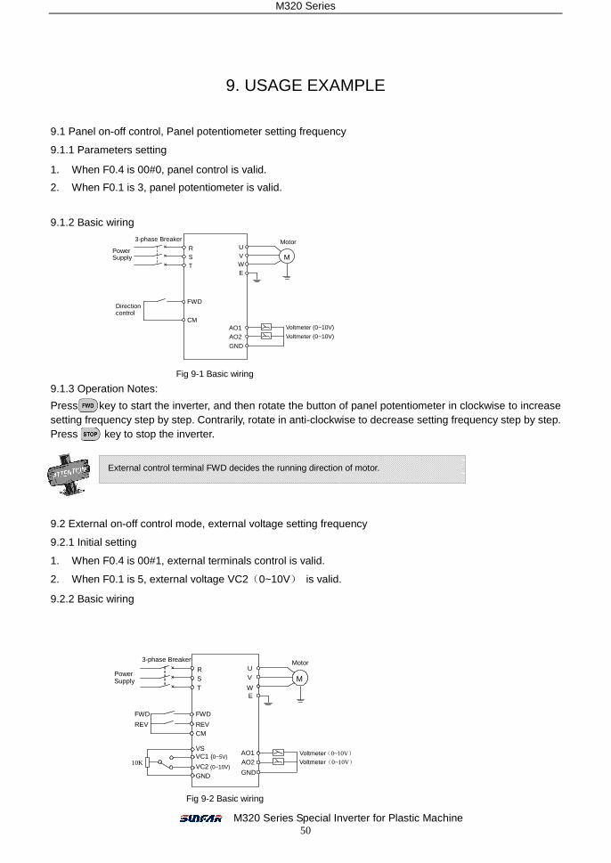
M320 Series
M320 Series Special Inverter for Plastic Machine 50
9. USAGE EXAMPLE
9.1 Panel on-off control, Panel potentiometer setting frequency
9.1.1 Parameters setting
1. When F0.4 is 00#0, panel control is valid.
2. When F0.1 is 3, panel potentiometer is valid.
9.1.2 Basic wiring
9.1.3 Operation Notes:
Press key to start the inverter, and then rotate the button of panel potentiometer in clockwise to increase setting frequency step by step. Contrarily, rotate in anti-clockwise to decrease setting frequency step by step. Press key to stop the inverter.
9.2 External on-off control mode, external voltage setting frequency
9.2.1 Initial setting
1. When F0.4 is 00#1, external terminals control is valid.
2. When F0.1 is 5, external voltage VC2(0~10V) is valid.
9.2.2 Basic wiring
Fig 9-1 Basic wiring
M
Motor U
W V
R S T
FWD
CM AO1 AO2
GND
Voltmeter (0~10V)
Direction control
E
× × ×
3-phase Breaker
Voltmeter (0~10V)
Power Supply
External control terminal FWD decides the running direction of motor.
M
Motor U
W
V R S T
FWD
REV
CM
AO1 AO2
GND
Voltmeter(0~10V)
FWD
REV
E
10K
VS VC1 (0~5V)
VC2 (0~10V) GND
× × ×
Voltmeter(0~10V)
3-phase Breaker
Power Supply
Fig 9-2 Basic wiring
M320 Series
M320 Series Special Inverter for Plastic Machine 51
9.2.3 Operation FWD-CM is off,the motor will run forward. REV-CM is off, the motor will run backward. FWD-CM and REV- CM are off or on at the same time, the inverter will stop. Setting frequency is set by external voltage signal VC2.
Control method of terminals FWD and REV is set by parameter F0.5.(See explanation
about parameter F0.5.
M320 Series
M320 Series Special Inverter for Plastic Machine 52
Floor 5 , 2nd floor, Zhonghang Shahe Industrial Park, Nanshan District, Shenzhen, PRC.
TEL : +86-755-26919258 FAX : +86-755-26919882
Commercial Hotline : +86-755-26609885, 26606885
Commercial FAX : +86-755-26912599
After-service Hotline : +86-755-26910928