Embed Size (px)
DESCRIPTION
elecrica matiz
Citation preview
1F – 280 ENGINE CONTROLS
DAEWOO M-150 BL2
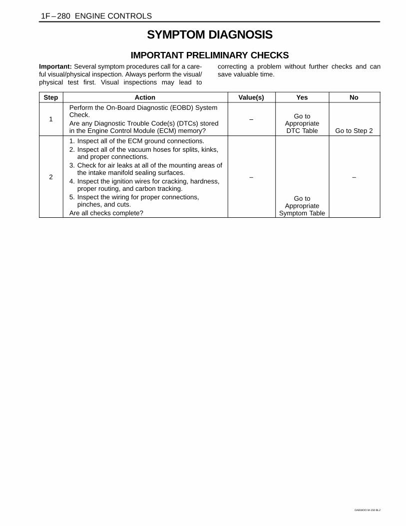
SYMPTOM DIAGNOSIS
IMPORTANT PRELIMINARY CHECKSImportant: Several symptom procedures call for a care-ful visual/physical inspection. Always perform the visual/physical test first. Visual inspections may lead to
correcting a problem without further checks and cansave valuable time.
Step Action Value(s) Yes No
1
Perform the On-Board Diagnostic (EOBD) SystemCheck.Are any Diagnostic Trouble Code(s) (DTCs) storedin the Engine Control Module (ECM) memory?
– Go toAppropriateDTC Table Go to Step 2
2
1. Inspect all of the ECM ground connections.2. Inspect all of the vacuum hoses for splits, kinks,
and proper connections.3. Check for air leaks at all of the mounting areas of
the intake manifold sealing surfaces.4. Inspect the ignition wires for cracking, hardness,
proper routing, and carbon tracking.5. Inspect the wiring for proper connections,
pinches, and cuts.Are all checks complete?
–
Go toAppropriate
Symptom Table
–
ENGINE CONTROLS 1F – 281
DAEWOO M-150 BL2
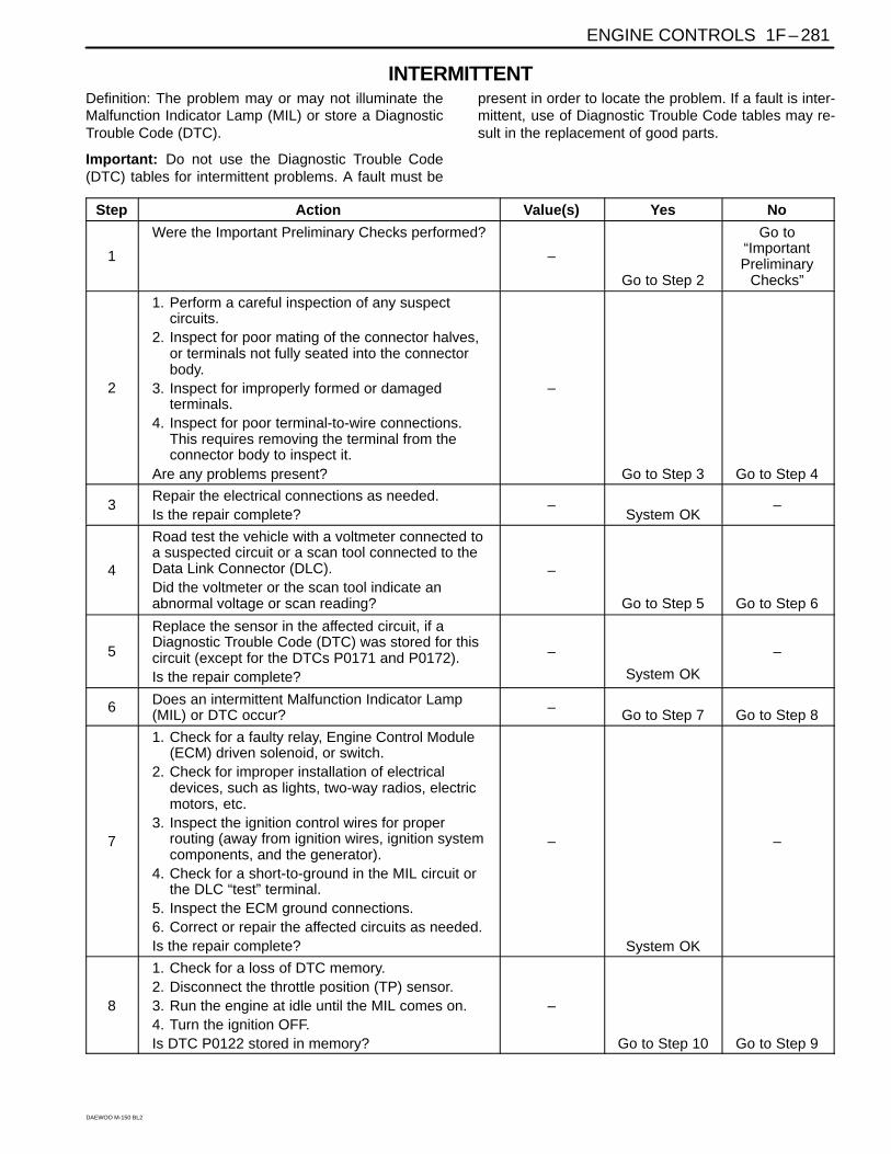
INTERMITTENTDefinition: The problem may or may not illuminate theMalfunction Indicator Lamp (MIL) or store a DiagnosticTrouble Code (DTC).
Important: Do not use the Diagnostic Trouble Code(DTC) tables for intermittent problems. A fault must be
present in order to locate the problem. If a fault is inter-mittent, use of Diagnostic Trouble Code tables may re-sult in the replacement of good parts.
Step Action Value(s) Yes No
1
Were the Important Preliminary Checks performed?
–
Go to Step 2
Go to“ImportantPreliminary
Checks”
2
1. Perform a careful inspection of any suspectcircuits.
2. Inspect for poor mating of the connector halves,or terminals not fully seated into the connectorbody.
3. Inspect for improperly formed or damagedterminals.
4. Inspect for poor terminal-to-wire connections.This requires removing the terminal from theconnector body to inspect it.
Are any problems present?
–
Go to Step 3 Go to Step 4
3Repair the electrical connections as needed.Is the repair complete?
–System OK
–
4
Road test the vehicle with a voltmeter connected toa suspected circuit or a scan tool connected to theData Link Connector (DLC).Did the voltmeter or the scan tool indicate anabnormal voltage or scan reading?
–
Go to Step 5 Go to Step 6
5
Replace the sensor in the affected circuit, if aDiagnostic Trouble Code (DTC) was stored for thiscircuit (except for the DTCs P0171 and P0172).Is the repair complete?
–
System OK
–
6 Does an intermittent Malfunction Indicator Lamp(MIL) or DTC occur? – Go to Step 7 Go to Step 8
7
1. Check for a faulty relay, Engine Control Module(ECM) driven solenoid, or switch.
2. Check for improper installation of electricaldevices, such as lights, two-way radios, electricmotors, etc.
3. Inspect the ignition control wires for properrouting (away from ignition wires, ignition systemcomponents, and the generator).
4. Check for a short-to-ground in the MIL circuit orthe DLC “test” terminal.
5. Inspect the ECM ground connections.6. Correct or repair the affected circuits as needed.Is the repair complete?
–
System OK
–
8
1. Check for a loss of DTC memory.2. Disconnect the throttle position (TP) sensor.3. Run the engine at idle until the MIL comes on.4. Turn the ignition OFF.Is DTC P0122 stored in memory?
–
Go to Step 10 Go to Step 9
1F – 282 ENGINE CONTROLS
DAEWOO M-150 BL2
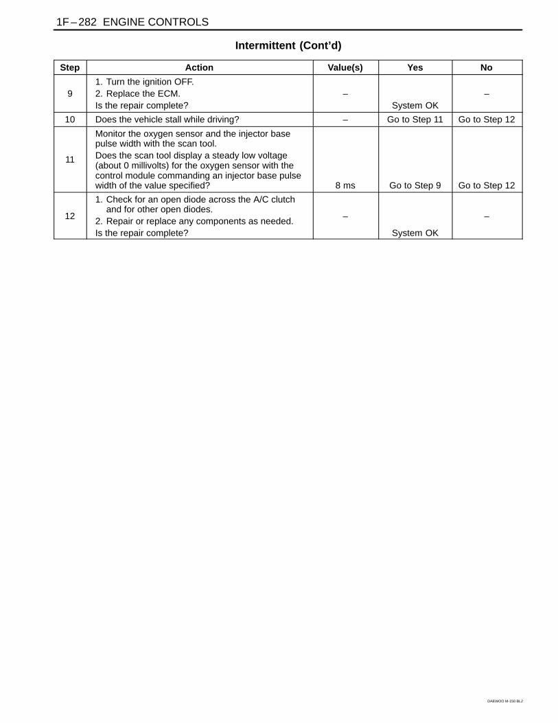
Intermittent (Cont’d)
Step Action Value(s) Yes No
91. Turn the ignition OFF.2. Replace the ECM.Is the repair complete?
–System OK
–
10 Does the vehicle stall while driving? – Go to Step 11 Go to Step 12
11
Monitor the oxygen sensor and the injector basepulse width with the scan tool.Does the scan tool display a steady low voltage(about 0 millivolts) for the oxygen sensor with thecontrol module commanding an injector base pulsewidth of the value specified? 8 ms Go to Step 9 Go to Step 12
12
1. Check for an open diode across the A/C clutchand for other open diodes.
2. Repair or replace any components as needed.Is the repair complete?
–
System OK
–
ENGINE CONTROLS 1F – 283
DAEWOO M-150 BL2
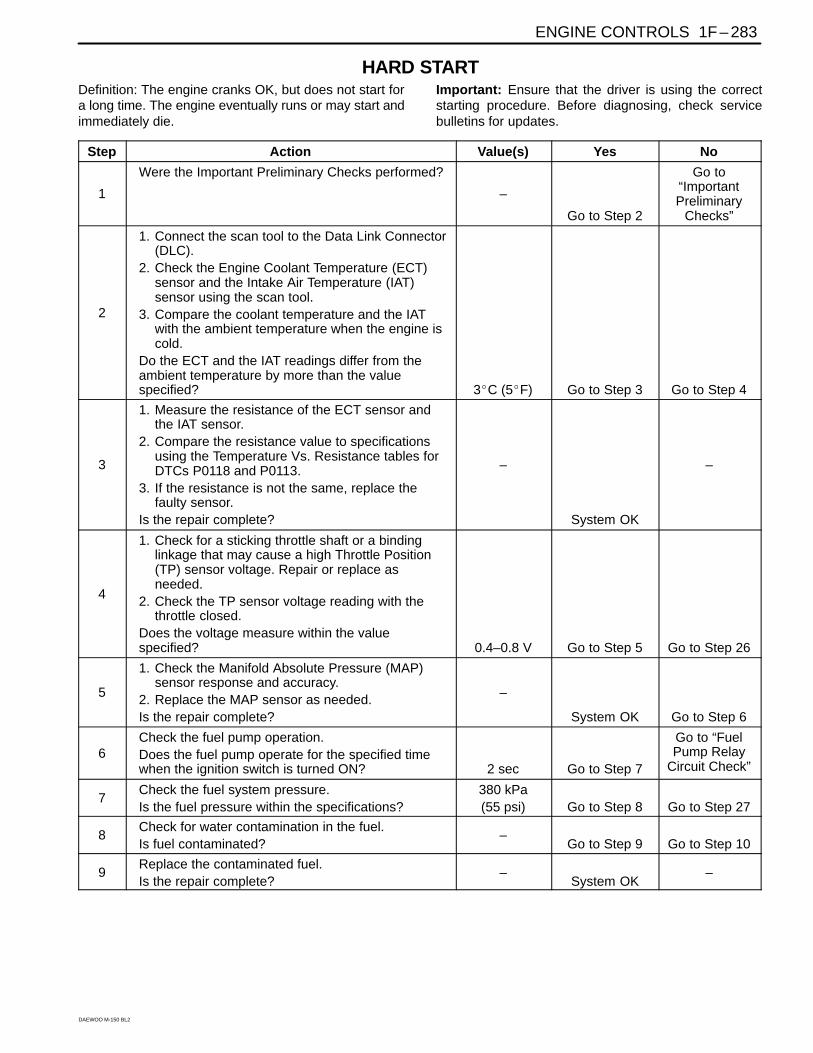
HARD STARTDefinition: The engine cranks OK, but does not start fora long time. The engine eventually runs or may start andimmediately die.
Important: Ensure that the driver is using the correctstarting procedure. Before diagnosing, check servicebulletins for updates.
Step Action Value(s) Yes No
1
Were the Important Preliminary Checks performed?
–
Go to Step 2
Go to“ImportantPreliminary
Checks”
2
1. Connect the scan tool to the Data Link Connector(DLC).
2. Check the Engine Coolant Temperature (ECT)sensor and the Intake Air Temperature (IAT)sensor using the scan tool.
3. Compare the coolant temperature and the IATwith the ambient temperature when the engine iscold.
Do the ECT and the IAT readings differ from theambient temperature by more than the valuespecified? 3C (5F) Go to Step 3 Go to Step 4
3
1. Measure the resistance of the ECT sensor andthe IAT sensor.
2. Compare the resistance value to specificationsusing the Temperature Vs. Resistance tables forDTCs P0118 and P0113.
3. If the resistance is not the same, replace thefaulty sensor.
Is the repair complete?
–
System OK
–
4
1. Check for a sticking throttle shaft or a bindinglinkage that may cause a high Throttle Position(TP) sensor voltage. Repair or replace asneeded.
2. Check the TP sensor voltage reading with thethrottle closed.
Does the voltage measure within the valuespecified? 0.4–0.8 V Go to Step 5 Go to Step 26
5
1. Check the Manifold Absolute Pressure (MAP)sensor response and accuracy.
2. Replace the MAP sensor as needed.Is the repair complete?
–
System OK Go to Step 6
6Check the fuel pump operation.Does the fuel pump operate for the specified timewhen the ignition switch is turned ON? 2 sec Go to Step 7
Go to “FuelPump Relay
Circuit Check”
7Check the fuel system pressure.Is the fuel pressure within the specifications?
380 kPa(55 psi) Go to Step 8 Go to Step 27
8Check for water contamination in the fuel.Is fuel contaminated?
–Go to Step 9 Go to Step 10
9Replace the contaminated fuel.Is the repair complete?
–System OK
–
1F – 284 ENGINE CONTROLS
DAEWOO M-150 BL2
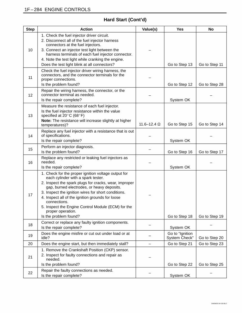
Hard Start (Cont’d)
Step Action Value(s) Yes No
10
1. Check the fuel injector driver circuit.2. Disconnect all of the fuel injector harness
connectors at the fuel injectors.3. Connect an injector test light between the
harness terminals of each fuel injector connector.4. Note the test light while cranking the engine.Does the test light blink at all connectors?
–
Go to Step 13 Go to Step 11
11
Check the fuel injector driver wiring harness, theconnectors, and the connector terminals for theproper connections.Is the problem found?
–
Go to Step 12 Go to Step 28
12Repair the wiring harness, the connector, or theconnector terminal as needed.Is the repair complete?
–System OK
–
13
Measure the resistance of each fuel injector.Is the fuel injector resistance within the valuespecified at 20C (68F)Note: The resistance will increase slightly at highertemperatures)? 11.6–12.4 Ω Go to Step 15 Go to Step 14
14Replace any fuel injector with a resistance that is outof specifications.Is the repair complete?
–System OK
–
15Perform an injector diagnosis.Is the problem found?
–Go to Step 16 Go to Step 17
16Replace any restricted or leaking fuel injectors asneeded.Is the repair complete?
–System OK
–
17
1. Check for the proper ignition voltage output foreach cylinder with a spark tester.
2. Inspect the spark plugs for cracks, wear, impropergap, burned electrodes, or heavy deposits.
3. Inspect the ignition wires for short conditions.4. Inspect all of the ignition grounds for loose
connections.5. Inspect the Engine Control Module (ECM) for the
proper operation.Is the problem found?
–
Go to Step 18 Go to Step 19
18Correct or replace any faulty ignition components.Is the repair complete?
–System OK
–
19 Does the engine misfire or cut out under load or atidle? – Go to “Ignition
System Check” Go to Step 20
20 Does the engine start, but then immediately stall? – Go to Step 21 Go to Step 23
21
1. Remove the Crankshaft Position (CKP) sensor.2. Inspect for faulty connections and repair as
needed.Is the problem found?
–
Go to Step 22 Go to Step 25
22Repair the faulty connections as needed.Is the repair complete?
–System OK
–
ENGINE CONTROLS 1F – 285
DAEWOO M-150 BL2
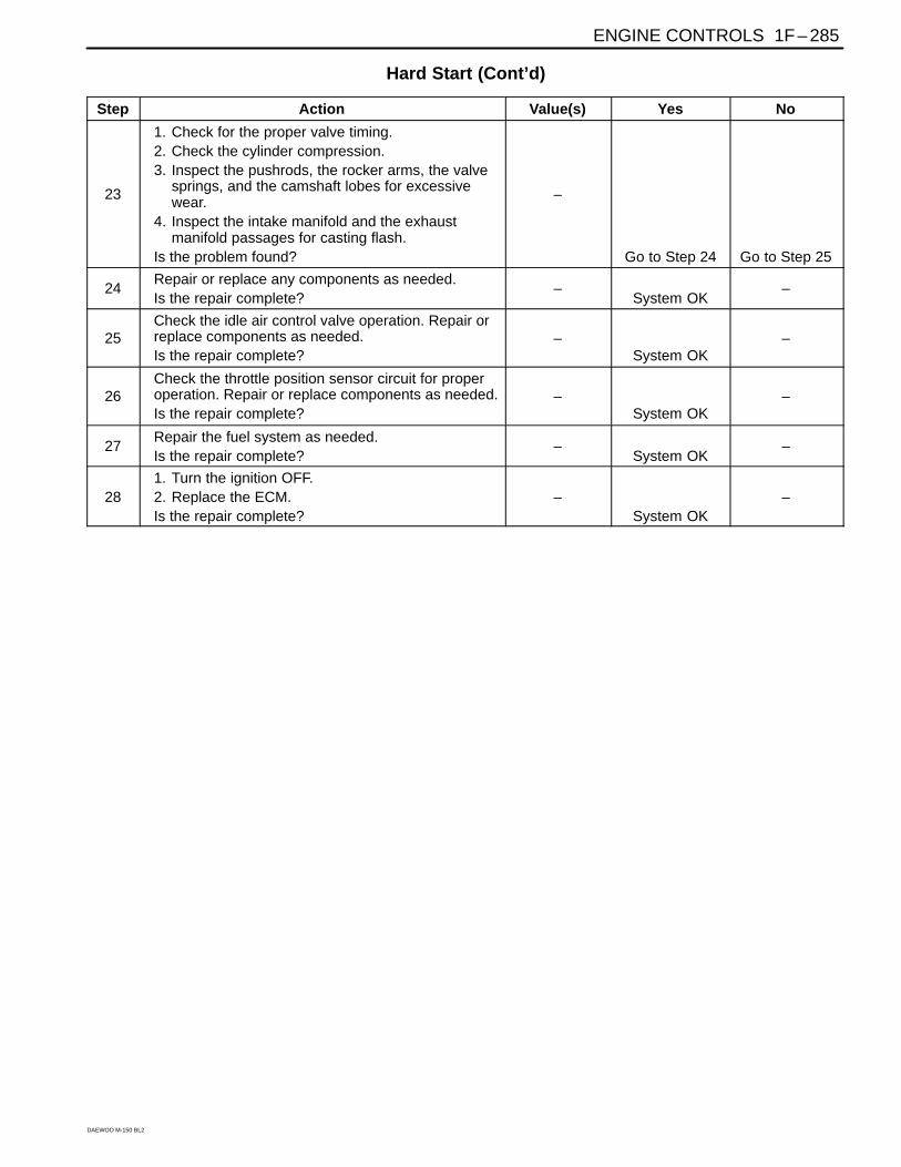
Hard Start (Cont’d)
Step Action Value(s) Yes No
23
1. Check for the proper valve timing.2. Check the cylinder compression.3. Inspect the pushrods, the rocker arms, the valve
springs, and the camshaft lobes for excessivewear.
4. Inspect the intake manifold and the exhaustmanifold passages for casting flash.
Is the problem found?
–
Go to Step 24 Go to Step 25
24Repair or replace any components as needed.Is the repair complete?
–System OK
–
25Check the idle air control valve operation. Repair orreplace components as needed.Is the repair complete?
–System OK
–
26Check the throttle position sensor circuit for properoperation. Repair or replace components as needed.Is the repair complete?
–System OK
–
27Repair the fuel system as needed.Is the repair complete?
–System OK
–
281. Turn the ignition OFF.2. Replace the ECM.Is the repair complete?
–System OK
–
1F – 286 ENGINE CONTROLS
DAEWOO M-150 BL2
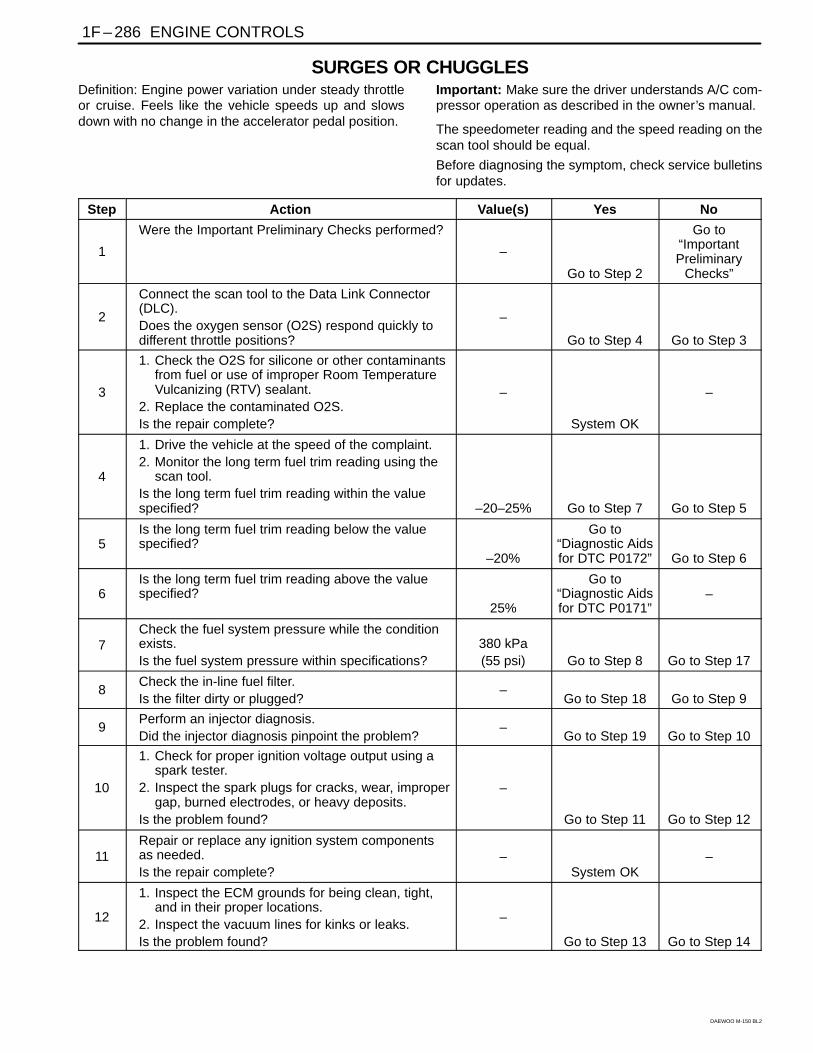
SURGES OR CHUGGLESDefinition: Engine power variation under steady throttleor cruise. Feels like the vehicle speeds up and slowsdown with no change in the accelerator pedal position.
Important: Make sure the driver understands A/C com-pressor operation as described in the owner’s manual.
The speedometer reading and the speed reading on thescan tool should be equal.
Before diagnosing the symptom, check service bulletinsfor updates.
Step Action Value(s) Yes No
1
Were the Important Preliminary Checks performed?
–
Go to Step 2
Go to“ImportantPreliminary
Checks”
2
Connect the scan tool to the Data Link Connector(DLC).Does the oxygen sensor (O2S) respond quickly todifferent throttle positions?
–
Go to Step 4 Go to Step 3
3
1. Check the O2S for silicone or other contaminantsfrom fuel or use of improper Room TemperatureVulcanizing (RTV) sealant.
2. Replace the contaminated O2S.Is the repair complete?
–
System OK
–
4
1. Drive the vehicle at the speed of the complaint.2. Monitor the long term fuel trim reading using the
scan tool.Is the long term fuel trim reading within the valuespecified? –20–25% Go to Step 7 Go to Step 5
5Is the long term fuel trim reading below the valuespecified?
–20%
Go to“Diagnostic Aidsfor DTC P0172” Go to Step 6
6Is the long term fuel trim reading above the valuespecified?
25%
Go to“Diagnostic Aidsfor DTC P0171”
–
7Check the fuel system pressure while the conditionexists.Is the fuel system pressure within specifications?
380 kPa(55 psi) Go to Step 8 Go to Step 17
8Check the in-line fuel filter.Is the filter dirty or plugged?
–Go to Step 18 Go to Step 9
9Perform an injector diagnosis.Did the injector diagnosis pinpoint the problem?
–Go to Step 19 Go to Step 10
10
1. Check for proper ignition voltage output using aspark tester.
2. Inspect the spark plugs for cracks, wear, impropergap, burned electrodes, or heavy deposits.
Is the problem found?
–
Go to Step 11 Go to Step 12
11Repair or replace any ignition system componentsas needed.Is the repair complete?
–System OK
–
12
1. Inspect the ECM grounds for being clean, tight,and in their proper locations.
2. Inspect the vacuum lines for kinks or leaks.Is the problem found?
–
Go to Step 13 Go to Step 14
ENGINE CONTROLS 1F – 287
DAEWOO M-150 BL2
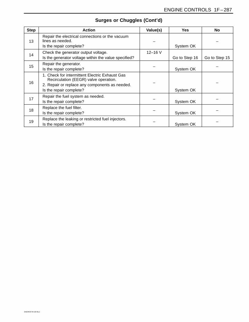
Surges or Chuggles (Cont’d)
Step Action Value(s) Yes No
13Repair the electrical connections or the vacuumlines as needed.Is the repair complete?
–System OK
–
14Check the generator output voltage.Is the generator voltage within the value specified?
12–16 VGo to Step 16 Go to Step 15
15Repair the generator.Is the repair complete?
–System OK
–
16
1. Check for intermittent Electric Exhaust GasRecirculation (EEGR) valve operation.
2. Repair or replace any components as needed.Is the repair complete?
–
System OK
–
17Repair the fuel system as needed.Is the repair complete?
–System OK
–
18Replace the fuel filter.Is the repair complete?
–System OK
–
19Replace the leaking or restricted fuel injectors.Is the repair complete?
–System OK
–
1F – 288 ENGINE CONTROLS
DAEWOO M-150 BL2
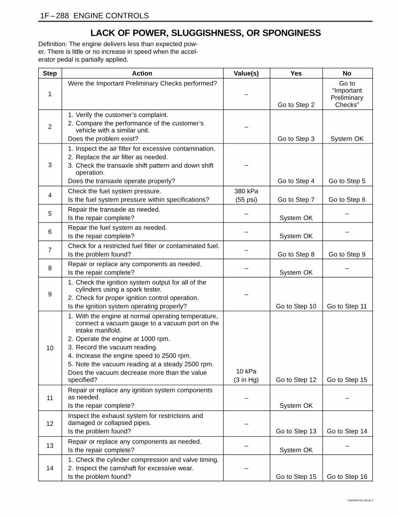
LACK OF POWER, SLUGGISHNESS, OR SPONGINESSDefinition: The engine delivers less than expected pow-er. There is little or no increase in speed when the accel-erator pedal is partially applied.
Step Action Value(s) Yes No
1
Were the Important Preliminary Checks performed?
–
Go to Step 2
Go to“ImportantPreliminary
Checks”
2
1. Verify the customer’s complaint.2. Compare the performance of the customer’s
vehicle with a similar unit.Does the problem exist?
–
Go to Step 3 System OK
3
1. Inspect the air filter for excessive contamination.2. Replace the air filter as needed.3. Check the transaxle shift pattern and down shift
operation.Does the transaxle operate properly?
–
Go to Step 4 Go to Step 5
4Check the fuel system pressure.Is the fuel system pressure within specifications?
380 kPa(55 psi) Go to Step 7 Go to Step 6
5Repair the transaxle as needed.Is the repair complete?
–System OK
–
6Repair the fuel system as needed.Is the repair complete?
–System OK
–
7Check for a restricted fuel filter or contaminated fuel.Is the problem found?
–Go to Step 8 Go to Step 9
8Repair or replace any components as needed.Is the repair complete?
–System OK
–
9
1. Check the ignition system output for all of thecylinders using a spark tester.
2. Check for proper ignition control operation.Is the ignition system operating properly?
–
Go to Step 10 Go to Step 11
10
1. With the engine at normal operating temperature,connect a vacuum gauge to a vacuum port on theintake manifold.
2. Operate the engine at 1000 rpm.3. Record the vacuum reading.4. Increase the engine speed to 2500 rpm.5. Note the vacuum reading at a steady 2500 rpm.Does the vacuum decrease more than the valuespecified?
10 kPa(3 in Hg) Go to Step 12 Go to Step 15
11Repair or replace any ignition system componentsas needed.Is the repair complete?
–System OK
–
12Inspect the exhaust system for restrictions anddamaged or collapsed pipes.Is the problem found?
–Go to Step 13 Go to Step 14
13Repair or replace any components as needed.Is the repair complete?
–System OK
–
141. Check the cylinder compression and valve timing.2. Inspect the camshaft for excessive wear.Is the problem found?
–Go to Step 15 Go to Step 16
ENGINE CONTROLS 1F – 289
DAEWOO M-150 BL2
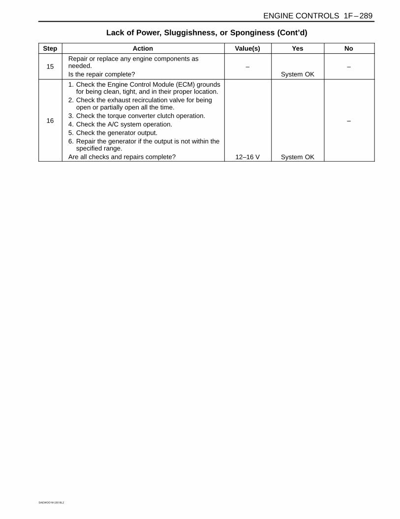
Lack of Power, Sluggishness, or Sponginess (Cont’d)
Step Action Value(s) Yes No
15Repair or replace any engine components asneeded.Is the repair complete?
–System OK
–
16
1. Check the Engine Control Module (ECM) groundsfor being clean, tight, and in their proper location.
2. Check the exhaust recirculation valve for beingopen or partially open all the time.
3. Check the torque converter clutch operation.4. Check the A/C system operation.5. Check the generator output.6. Repair the generator if the output is not within the
specified range.Are all checks and repairs complete? 12–16 V System OK
–
1F – 290 ENGINE CONTROLS
DAEWOO M-150 BL2
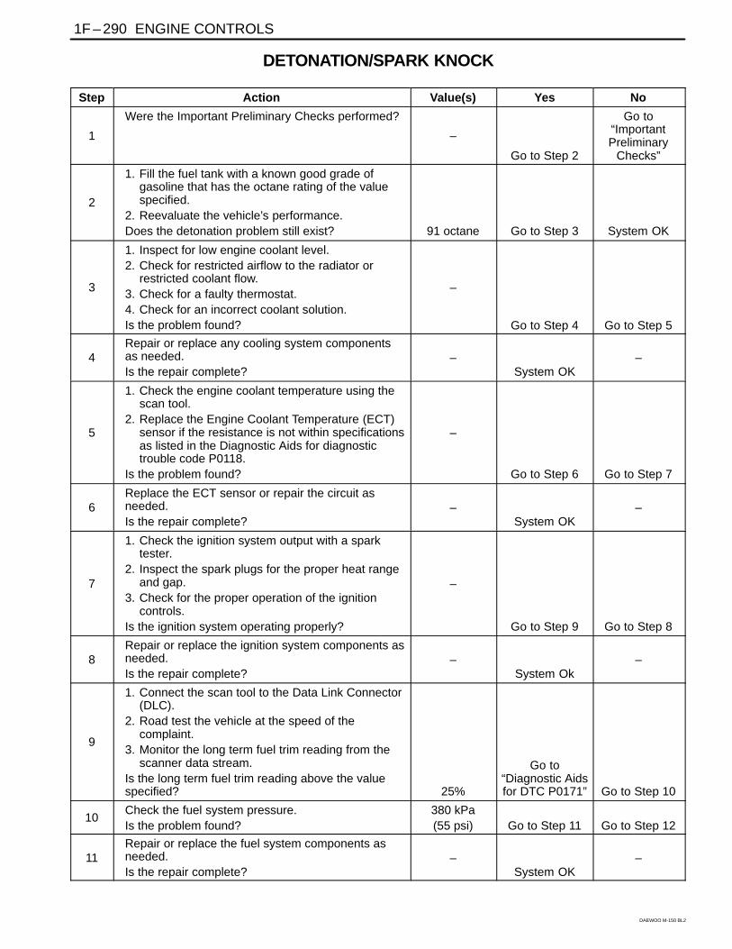
DETONATION/SPARK KNOCK
Step Action Value(s) Yes No
1
Were the Important Preliminary Checks performed?
–
Go to Step 2
Go to“ImportantPreliminary
Checks”
2
1. Fill the fuel tank with a known good grade ofgasoline that has the octane rating of the valuespecified.
2. Reevaluate the vehicle’s performance.Does the detonation problem still exist? 91 octane Go to Step 3 System OK
3
1. Inspect for low engine coolant level.2. Check for restricted airflow to the radiator or
restricted coolant flow.3. Check for a faulty thermostat.4. Check for an incorrect coolant solution.Is the problem found?
–
Go to Step 4 Go to Step 5
4Repair or replace any cooling system componentsas needed.Is the repair complete?
–System OK
–
5
1. Check the engine coolant temperature using thescan tool.
2. Replace the Engine Coolant Temperature (ECT)sensor if the resistance is not within specificationsas listed in the Diagnostic Aids for diagnostictrouble code P0118.
Is the problem found?
–
Go to Step 6 Go to Step 7
6Replace the ECT sensor or repair the circuit asneeded.Is the repair complete?
–System OK
–
7
1. Check the ignition system output with a sparktester.
2. Inspect the spark plugs for the proper heat rangeand gap.
3. Check for the proper operation of the ignitioncontrols.
Is the ignition system operating properly?
–
Go to Step 9 Go to Step 8
8Repair or replace the ignition system components asneeded.Is the repair complete?
–System Ok
–
9
1. Connect the scan tool to the Data Link Connector(DLC).
2. Road test the vehicle at the speed of thecomplaint.
3. Monitor the long term fuel trim reading from thescanner data stream.
Is the long term fuel trim reading above the valuespecified? 25%
Go to“Diagnostic Aidsfor DTC P0171” Go to Step 10
10Check the fuel system pressure.Is the problem found?
380 kPa(55 psi) Go to Step 11 Go to Step 12
11Repair or replace the fuel system components asneeded.Is the repair complete?
–System OK
–
ENGINE CONTROLS 1F – 291
DAEWOO M-150 BL2
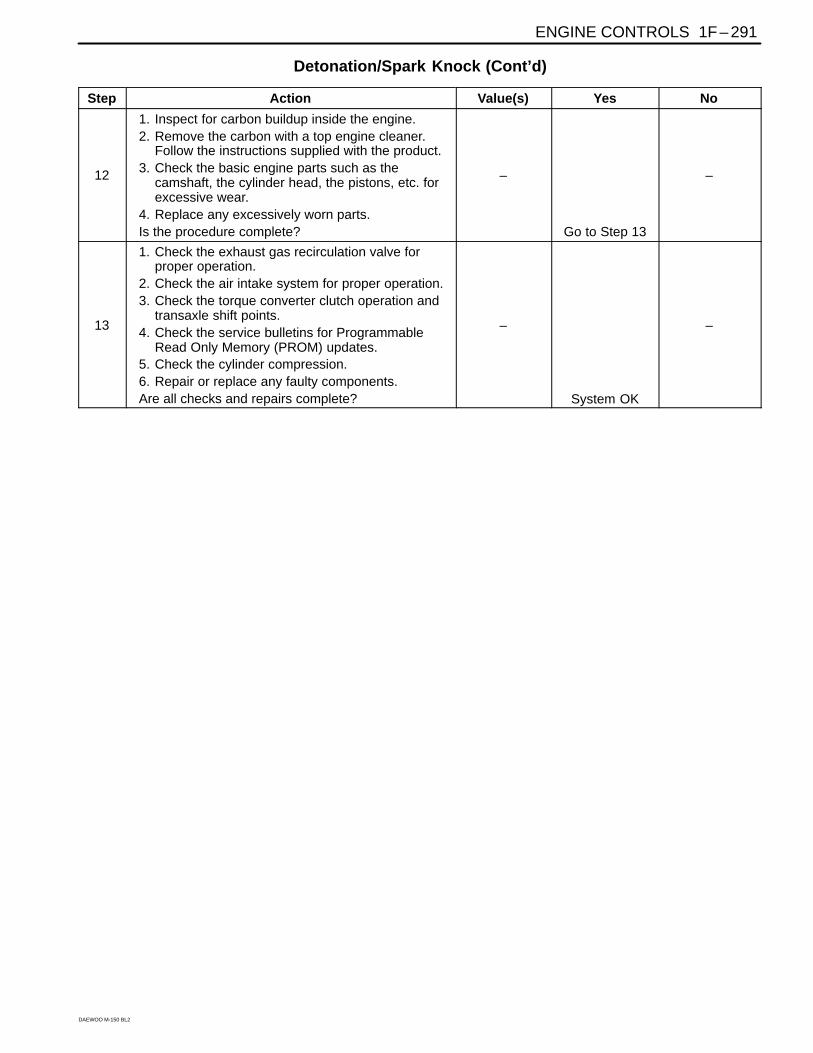
Detonation/Spark Knock (Cont’d)
Step Action Value(s) Yes No
12
1. Inspect for carbon buildup inside the engine.2. Remove the carbon with a top engine cleaner.
Follow the instructions supplied with the product.3. Check the basic engine parts such as the
camshaft, the cylinder head, the pistons, etc. forexcessive wear.
4. Replace any excessively worn parts.Is the procedure complete?
–
Go to Step 13
–
13
1. Check the exhaust gas recirculation valve forproper operation.
2. Check the air intake system for proper operation.3. Check the torque converter clutch operation and
transaxle shift points.4. Check the service bulletins for Programmable
Read Only Memory (PROM) updates.5. Check the cylinder compression.6. Repair or replace any faulty components.Are all checks and repairs complete?
–
System OK
–
1F – 292 ENGINE CONTROLS
DAEWOO M-150 BL2
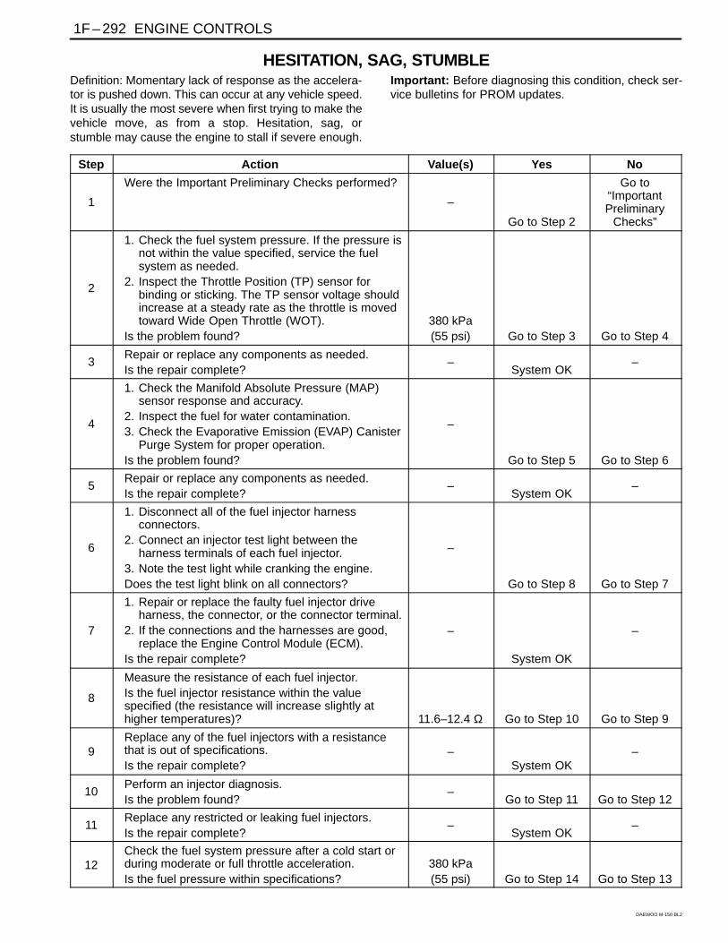
HESITATION, SAG, STUMBLEDefinition: Momentary lack of response as the accelera-tor is pushed down. This can occur at any vehicle speed.It is usually the most severe when first trying to make thevehicle move, as from a stop. Hesitation, sag, orstumble may cause the engine to stall if severe enough.
Important: Before diagnosing this condition, check ser-vice bulletins for PROM updates.
Step Action Value(s) Yes No
1
Were the Important Preliminary Checks performed?
–
Go to Step 2
Go to“ImportantPreliminary
Checks”
2
1. Check the fuel system pressure. If the pressure isnot within the value specified, service the fuelsystem as needed.
2. Inspect the Throttle Position (TP) sensor forbinding or sticking. The TP sensor voltage shouldincrease at a steady rate as the throttle is movedtoward Wide Open Throttle (WOT).
Is the problem found?380 kPa(55 psi) Go to Step 3 Go to Step 4
3Repair or replace any components as needed.Is the repair complete?
–System OK
–
4
1. Check the Manifold Absolute Pressure (MAP)sensor response and accuracy.
2. Inspect the fuel for water contamination.3. Check the Evaporative Emission (EVAP) Canister
Purge System for proper operation.Is the problem found?
–
Go to Step 5 Go to Step 6
5Repair or replace any components as needed.Is the repair complete?
–System OK
–
6
1. Disconnect all of the fuel injector harnessconnectors.
2. Connect an injector test light between theharness terminals of each fuel injector.
3. Note the test light while cranking the engine.Does the test light blink on all connectors?
–
Go to Step 8 Go to Step 7
7
1. Repair or replace the faulty fuel injector driveharness, the connector, or the connector terminal.
2. If the connections and the harnesses are good,replace the Engine Control Module (ECM).
Is the repair complete?
–
System OK
–
8
Measure the resistance of each fuel injector.Is the fuel injector resistance within the valuespecified (the resistance will increase slightly athigher temperatures)? 11.6–12.4 Ω Go to Step 10 Go to Step 9
9Replace any of the fuel injectors with a resistancethat is out of specifications.Is the repair complete?
–System OK
–
10Perform an injector diagnosis.Is the problem found?
–Go to Step 11 Go to Step 12
11Replace any restricted or leaking fuel injectors.Is the repair complete?
–System OK
–
12Check the fuel system pressure after a cold start orduring moderate or full throttle acceleration.Is the fuel pressure within specifications?
380 kPa(55 psi) Go to Step 14 Go to Step 13
ENGINE CONTROLS 1F – 293
DAEWOO M-150 BL2
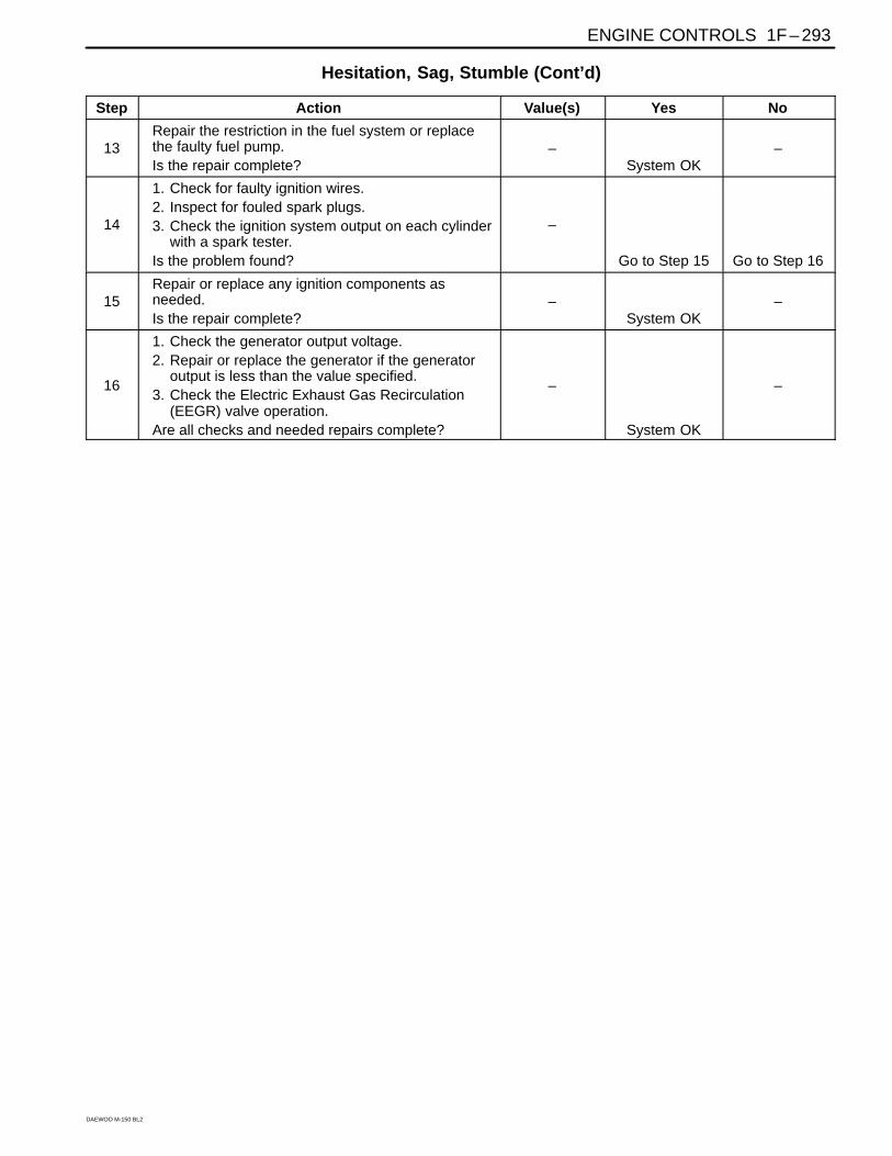
Hesitation, Sag, Stumble (Cont’d)
Step Action Value(s) Yes No
13Repair the restriction in the fuel system or replacethe faulty fuel pump.Is the repair complete?
–System OK
–
14
1. Check for faulty ignition wires.2. Inspect for fouled spark plugs.3. Check the ignition system output on each cylinder
with a spark tester.Is the problem found?
–
Go to Step 15 Go to Step 16
15Repair or replace any ignition components asneeded.Is the repair complete?
–System OK
–
16
1. Check the generator output voltage.2. Repair or replace the generator if the generator
output is less than the value specified.3. Check the Electric Exhaust Gas Recirculation
(EEGR) valve operation.Are all checks and needed repairs complete?
–
System OK
–
1F – 294 ENGINE CONTROLS
DAEWOO M-150 BL2
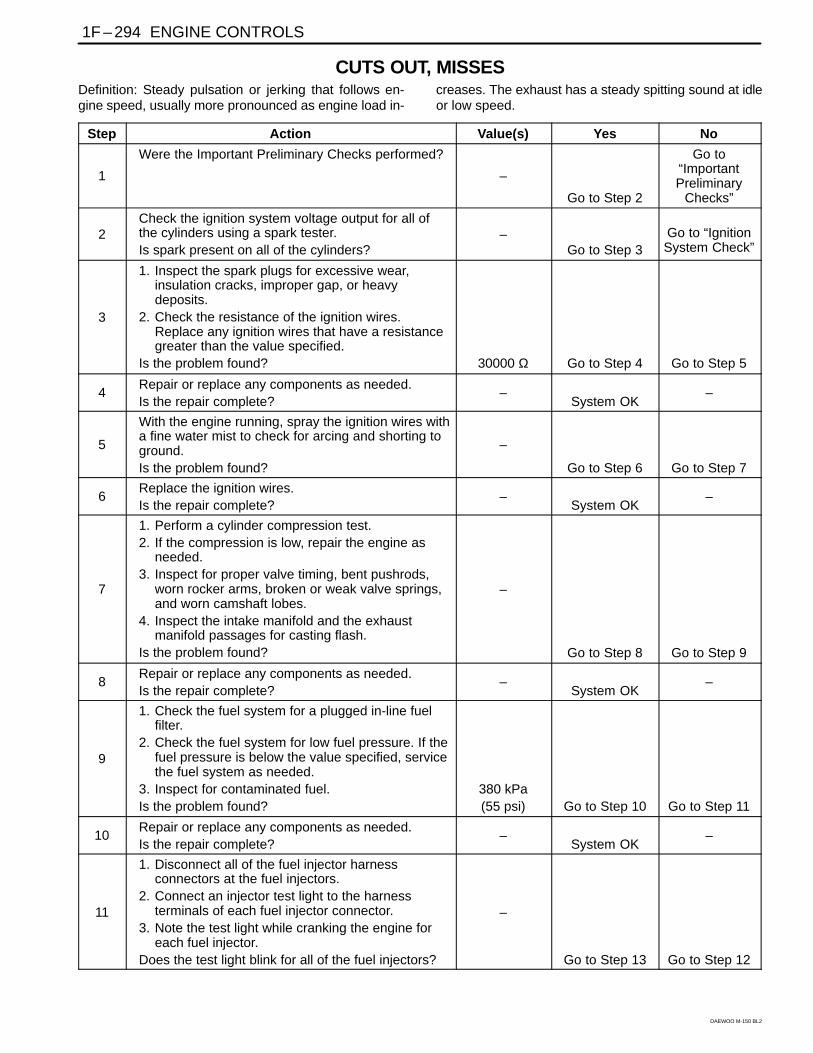
CUTS OUT, MISSESDefinition: Steady pulsation or jerking that follows en-gine speed, usually more pronounced as engine load in-
creases. The exhaust has a steady spitting sound at idleor low speed.
Step Action Value(s) Yes No
1
Were the Important Preliminary Checks performed?
–
Go to Step 2
Go to“ImportantPreliminary
Checks”
2Check the ignition system voltage output for all ofthe cylinders using a spark tester.Is spark present on all of the cylinders?
–Go to Step 3
Go to “IgnitionSystem Check”
3
1. Inspect the spark plugs for excessive wear,insulation cracks, improper gap, or heavydeposits.
2. Check the resistance of the ignition wires.Replace any ignition wires that have a resistancegreater than the value specified.
Is the problem found? 30000 Ω Go to Step 4 Go to Step 5
4Repair or replace any components as needed.Is the repair complete?
–System OK
–
5
With the engine running, spray the ignition wires witha fine water mist to check for arcing and shorting toground.Is the problem found?
–
Go to Step 6 Go to Step 7
6Replace the ignition wires.Is the repair complete?
–System OK
–
7
1. Perform a cylinder compression test.2. If the compression is low, repair the engine as
needed.3. Inspect for proper valve timing, bent pushrods,
worn rocker arms, broken or weak valve springs,and worn camshaft lobes.
4. Inspect the intake manifold and the exhaustmanifold passages for casting flash.
Is the problem found?
–
Go to Step 8 Go to Step 9
8Repair or replace any components as needed.Is the repair complete?
–System OK
–
9
1. Check the fuel system for a plugged in-line fuelfilter.
2. Check the fuel system for low fuel pressure. If thefuel pressure is below the value specified, servicethe fuel system as needed.
3. Inspect for contaminated fuel.Is the problem found?
380 kPa(55 psi) Go to Step 10 Go to Step 11
10Repair or replace any components as needed.Is the repair complete?
–System OK
–
11
1. Disconnect all of the fuel injector harnessconnectors at the fuel injectors.
2. Connect an injector test light to the harnessterminals of each fuel injector connector.
3. Note the test light while cranking the engine foreach fuel injector.
Does the test light blink for all of the fuel injectors?
–
Go to Step 13 Go to Step 12
ENGINE CONTROLS 1F – 295
DAEWOO M-150 BL2
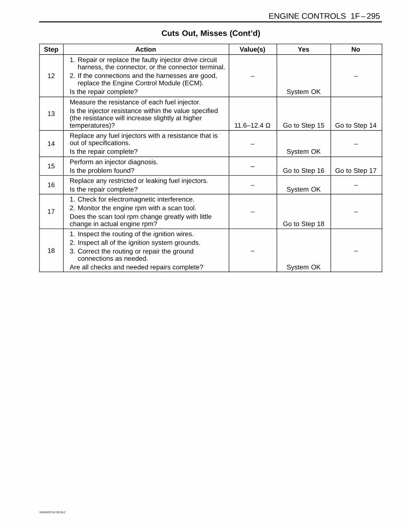
Cuts Out, Misses (Cont’d)
Step Action Value(s) Yes No
12
1. Repair or replace the faulty injector drive circuitharness, the connector, or the connector terminal.
2. If the connections and the harnesses are good,replace the Engine Control Module (ECM).
Is the repair complete?
–
System OK
–
13
Measure the resistance of each fuel injector.Is the injector resistance within the value specified(the resistance will increase slightly at highertemperatures)? 11.6–12.4 Ω Go to Step 15 Go to Step 14
14Replace any fuel injectors with a resistance that isout of specifications.Is the repair complete?
–System OK
–
15Perform an injector diagnosis.Is the problem found?
–Go to Step 16 Go to Step 17
16Replace any restricted or leaking fuel injectors.Is the repair complete?
–System OK
–
17
1. Check for electromagnetic interference.2. Monitor the engine rpm with a scan tool.Does the scan tool rpm change greatly with littlechange in actual engine rpm?
–
Go to Step 18
–
18
1. Inspect the routing of the ignition wires.2. Inspect all of the ignition system grounds.3. Correct the routing or repair the ground
connections as needed.Are all checks and needed repairs complete?
–
System OK
–
1F – 296 ENGINE CONTROLS
DAEWOO M-150 BL2
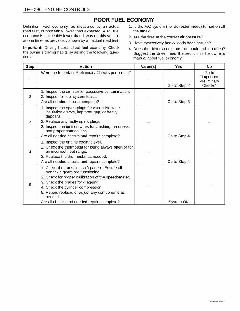
POOR FUEL ECONOMYDefinition: Fuel economy, as measured by an actualroad test, is noticeably lower than expected. Also, fueleconomy is noticeably lower than it was on this vehicleat one time, as previously shown by an actual road test.
Important: Driving habits affect fuel economy. Checkthe owner’s driving habits by asking the following ques-tions:
1. Is the A/C system (i.e. defroster mode) turned on allthe time?
2. Are the tires at the correct air pressure?
3. Have excessively heavy loads been carried?
4. Does the driver accelerate too much and too often?Suggest the driver read the section in the owner’smanual about fuel economy.
Step Action Value(s) Yes No
1
Were the Important Preliminary Checks performed?
–
Go to Step 2
Go to“ImportantPreliminary
Checks”
21. Inspect the air filter for excessive contamination.2. Inspect for fuel system leaks.Are all needed checks complete?
–Go to Step 3
–
3
1. Inspect the spark plugs for excessive wear,insulation cracks, improper gap, or heavydeposits.
2. Replace any faulty spark plugs.3. Inspect the ignition wires for cracking, hardness,
and proper connections.Are all needed checks and repairs complete?
–
Go to Step 4
–
4
1. Inspect the engine coolant level.2. Check the thermostat for being always open or for
an incorrect heat range.3. Replace the thermostat as needed.Are all needed checks and repairs complete?
–
Go to Step 4
–
5
1. Check the transaxle shift pattern. Ensure alltransaxle gears are functioning.
2. Check for proper calibration of the speedometer.3. Check the brakes for dragging.4. Check the cylinder compression.5. Repair, replace, or adjust any components as
needed.Are all checks and needed repairs complete?
–
System OK
–
ENGINE CONTROLS 1F – 297
DAEWOO M-150 BL2
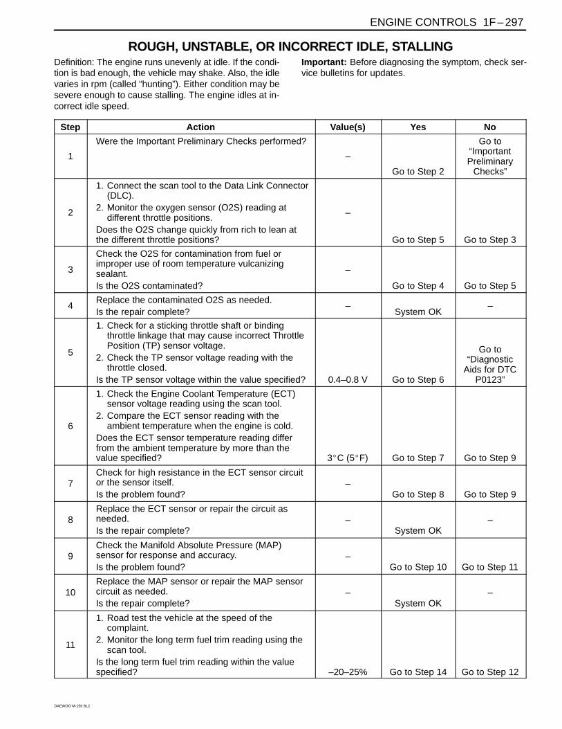
ROUGH, UNSTABLE, OR INCORRECT IDLE, STALLINGDefinition: The engine runs unevenly at idle. If the condi-tion is bad enough, the vehicle may shake. Also, the idlevaries in rpm (called “hunting”). Either condition may besevere enough to cause stalling. The engine idles at in-correct idle speed.
Important: Before diagnosing the symptom, check ser-vice bulletins for updates.
Step Action Value(s) Yes No
1
Were the Important Preliminary Checks performed?
–
Go to Step 2
Go to“ImportantPreliminary
Checks”
2
1. Connect the scan tool to the Data Link Connector(DLC).
2. Monitor the oxygen sensor (O2S) reading atdifferent throttle positions.
Does the O2S change quickly from rich to lean atthe different throttle positions?
–
Go to Step 5 Go to Step 3
3
Check the O2S for contamination from fuel orimproper use of room temperature vulcanizingsealant.Is the O2S contaminated?
–
Go to Step 4 Go to Step 5
4Replace the contaminated O2S as needed.Is the repair complete?
–System OK
–
5
1. Check for a sticking throttle shaft or bindingthrottle linkage that may cause incorrect ThrottlePosition (TP) sensor voltage.
2. Check the TP sensor voltage reading with thethrottle closed.
Is the TP sensor voltage within the value specified? 0.4–0.8 V Go to Step 6
Go to“Diagnostic
Aids for DTCP0123”
6
1. Check the Engine Coolant Temperature (ECT)sensor voltage reading using the scan tool.
2. Compare the ECT sensor reading with theambient temperature when the engine is cold.
Does the ECT sensor temperature reading differfrom the ambient temperature by more than thevalue specified? 3C (5F) Go to Step 7 Go to Step 9
7Check for high resistance in the ECT sensor circuitor the sensor itself.Is the problem found?
–Go to Step 8 Go to Step 9
8Replace the ECT sensor or repair the circuit asneeded.Is the repair complete?
–System OK
–
9Check the Manifold Absolute Pressure (MAP)sensor for response and accuracy.Is the problem found?
–Go to Step 10 Go to Step 11
10Replace the MAP sensor or repair the MAP sensorcircuit as needed.Is the repair complete?
–System OK
–
11
1. Road test the vehicle at the speed of thecomplaint.
2. Monitor the long term fuel trim reading using thescan tool.
Is the long term fuel trim reading within the valuespecified? –20–25% Go to Step 14 Go to Step 12
1F – 298 ENGINE CONTROLS
DAEWOO M-150 BL2
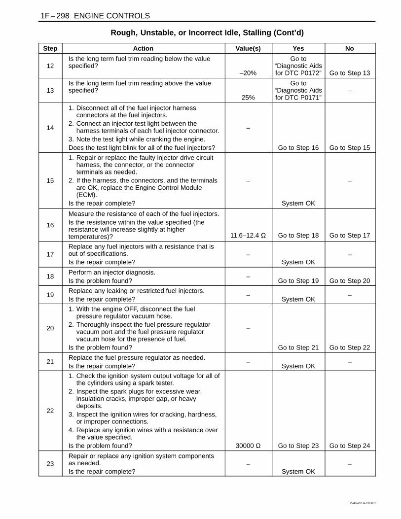
Rough, Unstable, or Incorrect Idle, Stalling (Cont’d)
Step Action Value(s) Yes No
12Is the long term fuel trim reading below the valuespecified?
–20%
Go to“Diagnostic Aidsfor DTC P0172” Go to Step 13
13Is the long term fuel trim reading above the valuespecified?
25%
Go to“Diagnostic Aidsfor DTC P0171”
–
14
1. Disconnect all of the fuel injector harnessconnectors at the fuel injectors.
2. Connect an injector test light between theharness terminals of each fuel injector connector.
3. Note the test light while cranking the engine.Does the test light blink for all of the fuel injectors?
–
Go to Step 16 Go to Step 15
15
1. Repair or replace the faulty injector drive circuitharness, the connector, or the connectorterminals as needed.
2. If the harness, the connectors, and the terminalsare OK, replace the Engine Control Module(ECM).
Is the repair complete?
–
System OK
–
16
Measure the resistance of each of the fuel injectors.Is the resistance within the value specified (theresistance will increase slightly at highertemperatures)? 11.6–12.4 Ω Go to Step 18 Go to Step 17
17Replace any fuel injectors with a resistance that isout of specifications.Is the repair complete?
–System OK
–
18Perform an injector diagnosis.Is the problem found?
–Go to Step 19 Go to Step 20
19Replace any leaking or restricted fuel injectors.Is the repair complete?
–System OK
–
20
1. With the engine OFF, disconnect the fuelpressure regulator vacuum hose.
2. Thoroughly inspect the fuel pressure regulatorvacuum port and the fuel pressure regulatorvacuum hose for the presence of fuel.
Is the problem found?
–
Go to Step 21 Go to Step 22
21Replace the fuel pressure regulator as needed.Is the repair complete?
–System OK
–
22
1. Check the ignition system output voltage for all ofthe cylinders using a spark tester.
2. Inspect the spark plugs for excessive wear,insulation cracks, improper gap, or heavydeposits.
3. Inspect the ignition wires for cracking, hardness,or improper connections.
4. Replace any ignition wires with a resistance overthe value specified.
Is the problem found? 30000 Ω Go to Step 23 Go to Step 24
23Repair or replace any ignition system componentsas needed.Is the repair complete?
–System OK
–
ENGINE CONTROLS 1F – 299
DAEWOO M-150 BL2
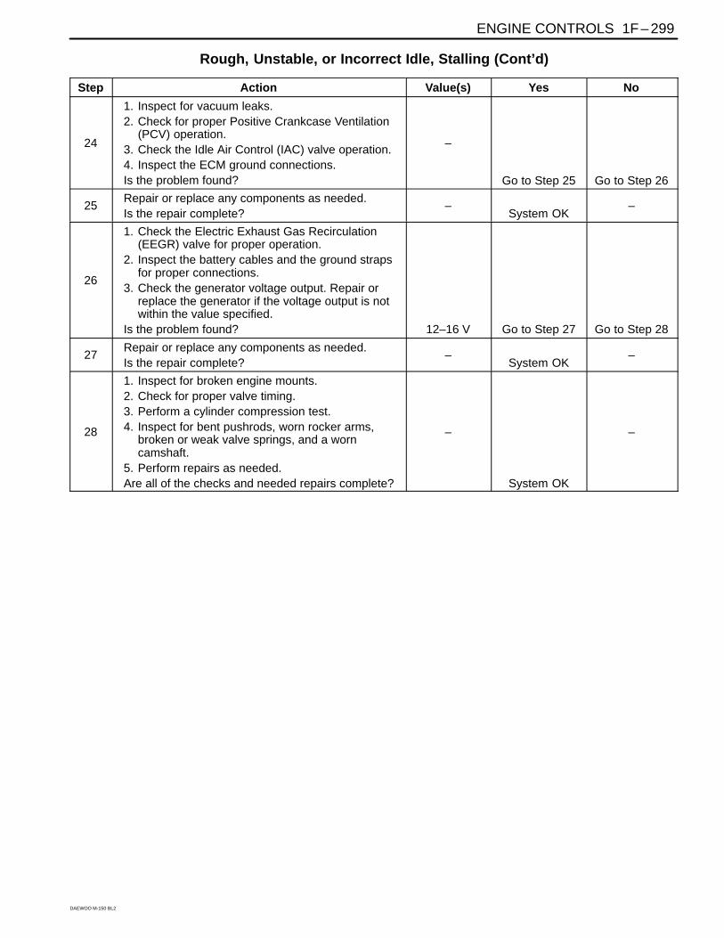
Rough, Unstable, or Incorrect Idle, Stalling (Cont’d)
Step Action Value(s) Yes No
24
1. Inspect for vacuum leaks.2. Check for proper Positive Crankcase Ventilation
(PCV) operation.3. Check the Idle Air Control (IAC) valve operation.4. Inspect the ECM ground connections.Is the problem found?
–
Go to Step 25 Go to Step 26
25Repair or replace any components as needed.Is the repair complete?
–System OK
–
26
1. Check the Electric Exhaust Gas Recirculation(EEGR) valve for proper operation.
2. Inspect the battery cables and the ground strapsfor proper connections.
3. Check the generator voltage output. Repair orreplace the generator if the voltage output is notwithin the value specified.
Is the problem found? 12–16 V Go to Step 27 Go to Step 28
27Repair or replace any components as needed.Is the repair complete?
–System OK
–
28
1. Inspect for broken engine mounts.2. Check for proper valve timing.3. Perform a cylinder compression test.4. Inspect for bent pushrods, worn rocker arms,
broken or weak valve springs, and a worncamshaft.
5. Perform repairs as needed.Are all of the checks and needed repairs complete?
–
System OK
–
1F – 300 ENGINE CONTROLS
DAEWOO M-150 BL2
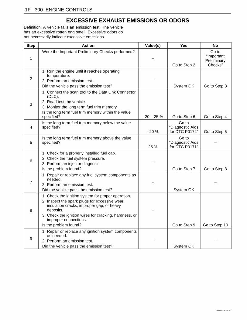
EXCESSIVE EXHAUST EMISSIONS OR ODORSDefinition: A vehicle fails an emission test. The vehiclehas an excessive rotten egg smell. Excessive odors donot necessarily indicate excessive emissions.
Step Action Value(s) Yes No
1
Were the Important Preliminary Checks performed?
–
Go to Step 2
Go to“ImportantPreliminary
Checks”
2
1. Run the engine until it reaches operatingtemperature.
2. Perform an emission test.Did the vehicle pass the emission test?
–
System OK Go to Step 3
3
1. Connect the scan tool to the Data Link Connector(DLC).
2. Road test the vehicle.3. Monitor the long term fuel trim memory.Is the long term fuel trim memory within the valuespecified? –20 – 25 % Go to Step 6 Go to Step 4
4Is the long term fuel trim memory below the valuespecified?
–20 %
Go to“Diagnostic Aidsfor DTC P0172” Go to Step 5
5Is the long term fuel trim memory above the valuespecified?
25 %
Go to“Diagnostic Aidsfor DTC P0171”
–
6
1. Check for a properly installed fuel cap.2. Check the fuel system pressure.3. Perform an injector diagnosis.Is the problem found?
–
Go to Step 7 Go to Step 8
7
1. Repair or replace any fuel system components asneeded.
2. Perform an emission test.Did the vehicle pass the emission test?
–
System OK
–
8
1. Check the ignition system for proper operation.2. Inspect the spark plugs for excessive wear,
insulation cracks, improper gap, or heavydeposits.
3. Check the ignition wires for cracking, hardness, orimproper connections.
Is the problem found?
–
Go to Step 9 Go to Step 10
9
1. Repair or replace any ignition system componentsas needed.
2. Perform an emission test.Did the vehicle pass the emission test?
–
System OK
–
ENGINE CONTROLS 1F – 301
DAEWOO M-150 BL2
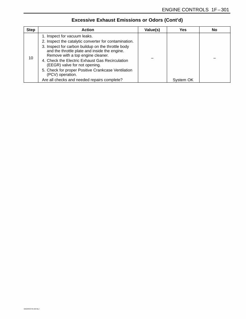
Excessive Exhaust Emissions or Odors (Cont’d)
Step Action Value(s) Yes No
10
1. Inspect for vacuum leaks.2. Inspect the catalytic converter for contamination.3. Inspect for carbon buildup on the throttle body
and the throttle plate and inside the engine.Remove with a top engine cleaner.
4. Check the Electric Exhaust Gas Recirculation(EEGR) valve for not opening.
5. Check for proper Positive Crankcase Ventilation(PCV) operation.
Are all checks and needed repairs complete?
–
System OK
–
1F – 302 ENGINE CONTROLS
DAEWOO M-150 BL2
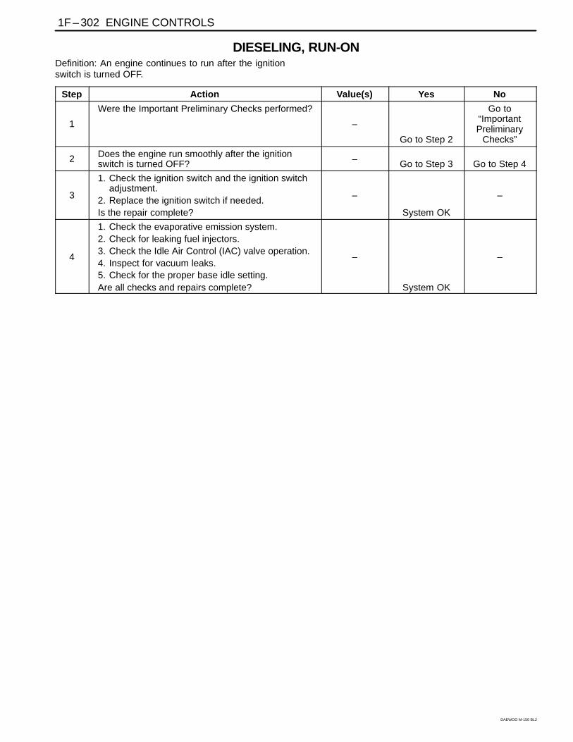
DIESELING, RUN-ONDefinition: An engine continues to run after the ignitionswitch is turned OFF.
Step Action Value(s) Yes No
1
Were the Important Preliminary Checks performed?
–
Go to Step 2
Go to“ImportantPreliminary
Checks”
2 Does the engine run smoothly after the ignitionswitch is turned OFF? – Go to Step 3 Go to Step 4
3
1. Check the ignition switch and the ignition switchadjustment.
2. Replace the ignition switch if needed.Is the repair complete?
–
System OK
–
4
1. Check the evaporative emission system.2. Check for leaking fuel injectors.3. Check the Idle Air Control (IAC) valve operation.4. Inspect for vacuum leaks.5. Check for the proper base idle setting.Are all checks and repairs complete?
–
System OK
–
ENGINE CONTROLS 1F – 303
DAEWOO M-150 BL2
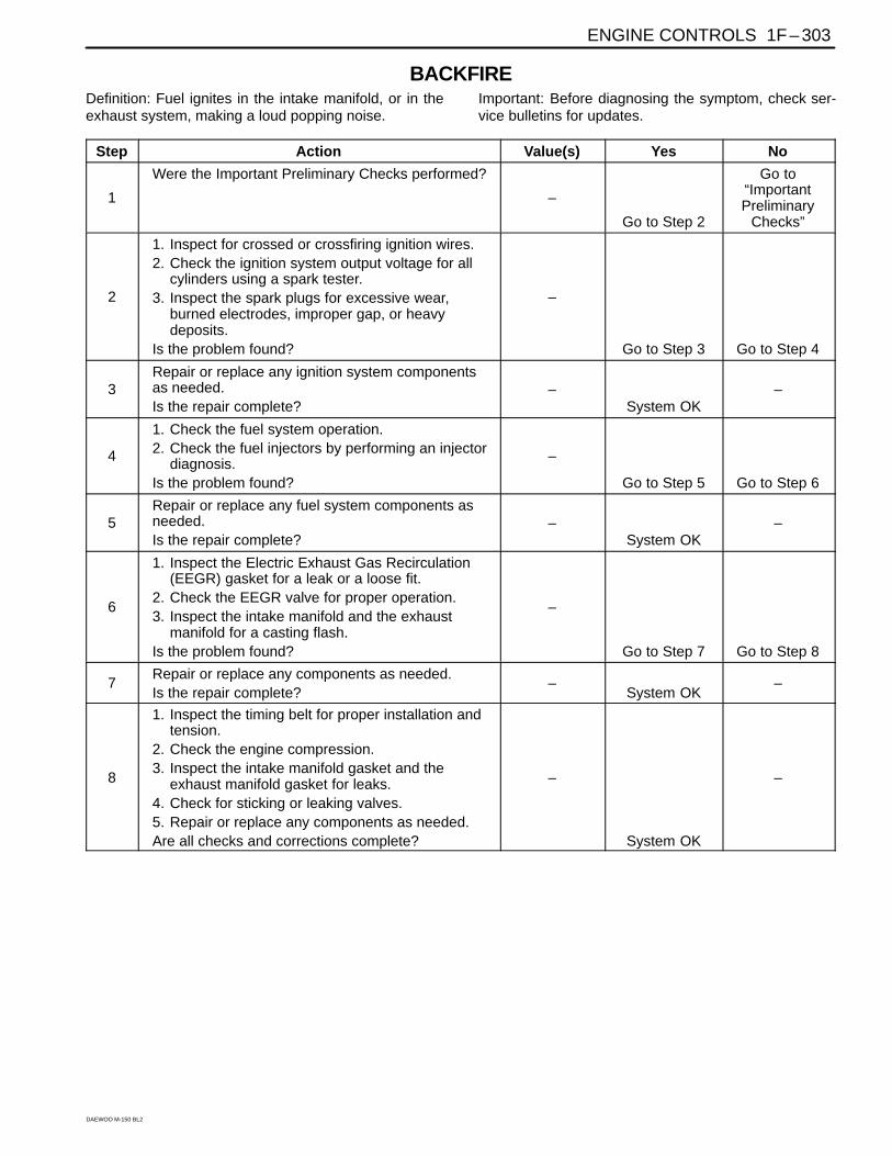
BACKFIREDefinition: Fuel ignites in the intake manifold, or in theexhaust system, making a loud popping noise.
Important: Before diagnosing the symptom, check ser-vice bulletins for updates.
Step Action Value(s) Yes No
1
Were the Important Preliminary Checks performed?
–
Go to Step 2
Go to“ImportantPreliminary
Checks”
2
1. Inspect for crossed or crossfiring ignition wires.2. Check the ignition system output voltage for all
cylinders using a spark tester.3. Inspect the spark plugs for excessive wear,
burned electrodes, improper gap, or heavydeposits.
Is the problem found?
–
Go to Step 3 Go to Step 4
3Repair or replace any ignition system componentsas needed.Is the repair complete?
–System OK
–
4
1. Check the fuel system operation.2. Check the fuel injectors by performing an injector
diagnosis.Is the problem found?
–
Go to Step 5 Go to Step 6
5Repair or replace any fuel system components asneeded.Is the repair complete?
–System OK
–
6
1. Inspect the Electric Exhaust Gas Recirculation(EEGR) gasket for a leak or a loose fit.
2. Check the EEGR valve for proper operation.3. Inspect the intake manifold and the exhaust
manifold for a casting flash.Is the problem found?
–
Go to Step 7 Go to Step 8
7Repair or replace any components as needed.Is the repair complete?
–System OK
–
8
1. Inspect the timing belt for proper installation andtension.
2. Check the engine compression.3. Inspect the intake manifold gasket and the
exhaust manifold gasket for leaks.4. Check for sticking or leaking valves.5. Repair or replace any components as needed.Are all checks and corrections complete?
–
System OK
–
1F – 304 ENGINE CONTROLS
DAEWOO M-150 BL2
REPAIR INSTRUCTIONS
ON-VEHICLE SERVICE
D102F502
D102F501
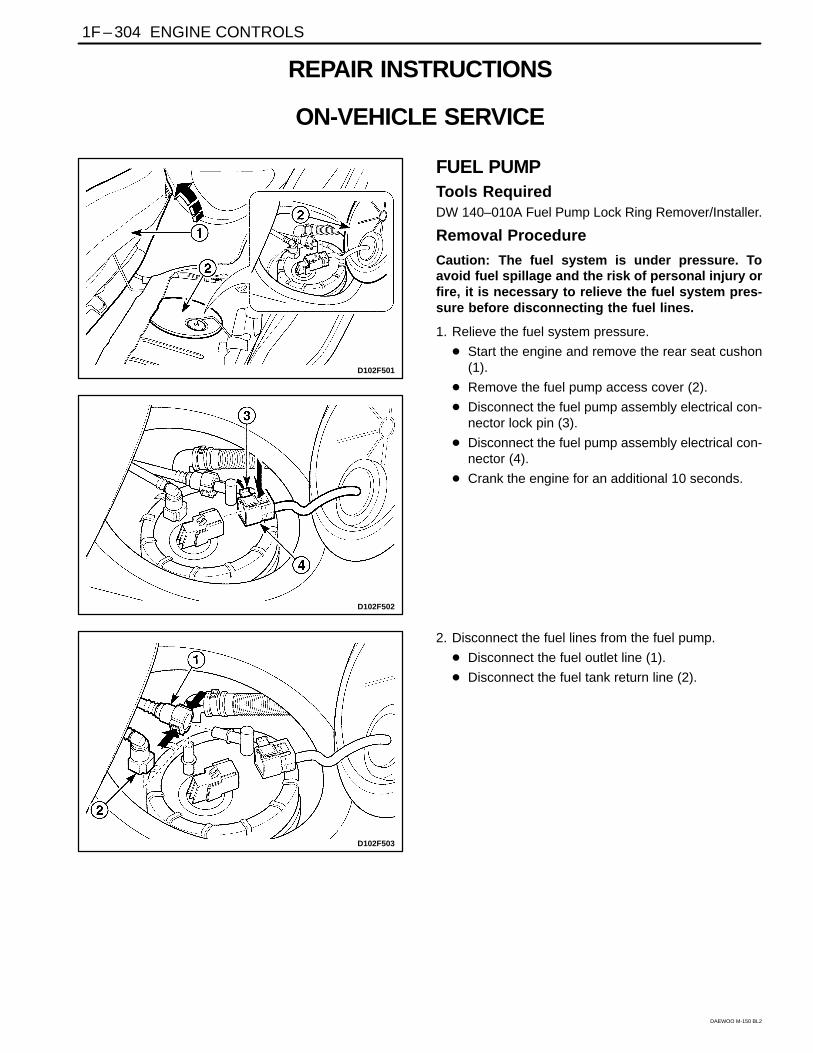
FUEL PUMPTools RequiredDW 140–010A Fuel Pump Lock Ring Remover/Installer.
Removal Procedure
Caution: The fuel system is under pressure. Toavoid fuel spillage and the risk of personal injury orfire, it is necessary to relieve the fuel system pres-sure before disconnecting the fuel lines.
1. Relieve the fuel system pressure.
Start the engine and remove the rear seat cushon(1).
Remove the fuel pump access cover (2).
Disconnect the fuel pump assembly electrical con-nector lock pin (3).
Disconnect the fuel pump assembly electrical con-nector (4).
Crank the engine for an additional 10 seconds.
D102F503
2. Disconnect the fuel lines from the fuel pump.
Disconnect the fuel outlet line (1).
Disconnect the fuel tank return line (2).
ENGINE CONTROLS 1F – 305
DAEWOO M-150 BL2
D12F504A
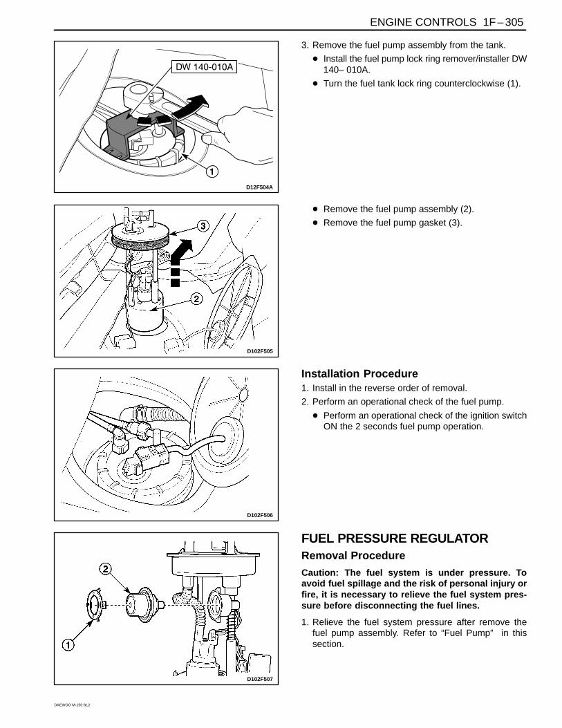
3. Remove the fuel pump assembly from the tank.
Install the fuel pump lock ring remover/installer DW140– 010A.
Turn the fuel tank lock ring counterclockwise (1).
D102F505
Remove the fuel pump assembly (2).
Remove the fuel pump gasket (3).
D102F506
Installation Procedure1. Install in the reverse order of removal.
2. Perform an operational check of the fuel pump.
Perform an operational check of the ignition switchON the 2 seconds fuel pump operation.
D102F507
FUEL PRESSURE REGULATORRemoval Procedure
Caution: The fuel system is under pressure. Toavoid fuel spillage and the risk of personal injury orfire, it is necessary to relieve the fuel system pres-sure before disconnecting the fuel lines.
1. Relieve the fuel system pressure after remove thefuel pump assembly. Refer to “Fuel Pump” in thissection.
1F – 306 ENGINE CONTROLS
DAEWOO M-150 BL2
D102F508
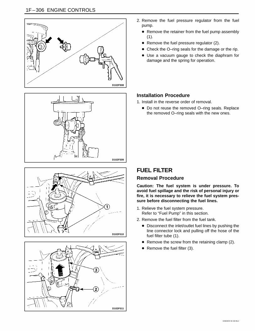
2. Remove the fuel pressure regulator from the fuelpump.
Remove the retainer from the fuel pump assembly(1).
Remove the fuel pressure regulator (2).
Check the O–ring seals for the damage or the rip.
Use a vacuum gauge to check the diaphram fordamage and the spring for operation.
D102F509
Installation Procedure1. Install in the reverse order of removal.
Do not reuse the removed O–ring seals. Replacethe removed O–ring seals with the new ones.
D102F511
D102F510
FUEL FILTERRemoval Procedure
Caution: The fuel system is under pressure. Toavoid fuel spillage and the risk of personal injury orfire, it is necessary to relieve the fuel system pres-sure before disconnecting the fuel lines.
1. Relieve the fuel system pressure. Refer to “Fuel Pump” in this section.
2. Remove the fuel filter from the fuel tank.
Disconnect the inlet/outlet fuel lines by pushing theline connector lock and pulling off the hose of thefuel filter tube (1).
Remove the screw from the retaining clamp (2).
Remove the fuel filter (3).
ENGINE CONTROLS 1F – 307
DAEWOO M-150 BL2
D102F512
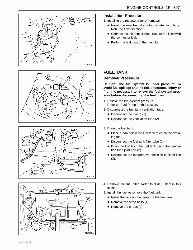
Installation Procedure1. Install in the reverse order of removal.
Install the new fuel filter into the retaining clamp.Note the flow direction.
Connect the inlet/outlet lines. Secure the lines withthe connector lock.
Perform a leak test of the fuel filter.
D102F514
D102F513
FUEL TANKRemoval Procedure
Caution: The fuel system is under pressure. Toavoid fuel spillage and the risk of personal injury orfire, it is necessary to relieve the fuel system pres-sure before disconnecting the fuel lines.
1. Relieve the fuel system pressure. Refer to “Fuel Pump” in this section.
2. Disconnect the fuel tank ventilation tube.
Disconnect the clamp (1).
Disconnect the ventilation tube (2).
3. Drain the fuel tank.
Place a pan below the fuel tank to catch the drain-ing fuel.
Disconnect the fuel tank filter tube (1).
Drain the fuel from the fuel tank using the ventila-tion tube joint port (2).
Disconnect the evaporative emission canister line(3).
D12F515A
4. Remove the fuel filter. Refer to “Fuel Filter” in thissection.
5. Install the jack to remove the fuel tank.
Install the jack on the center of the fuel tank.
Remove the strap bolts (1).
Remove the straps (2).
1F – 308 ENGINE CONTROLS
DAEWOO M-150 BL2
D102F516
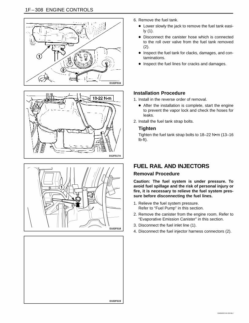
6. Remove the fuel tank.
Lower slowly the jack to remove the fuel tank easi-ly (1).
Disconnect the canister hose which is connectedto the roll over valve from the fuel tank removed(2).
Inspect the fuel tank for clacks, damages, and con-taminations.
Inspect the fuel lines for cracks and damages.
D12F517A
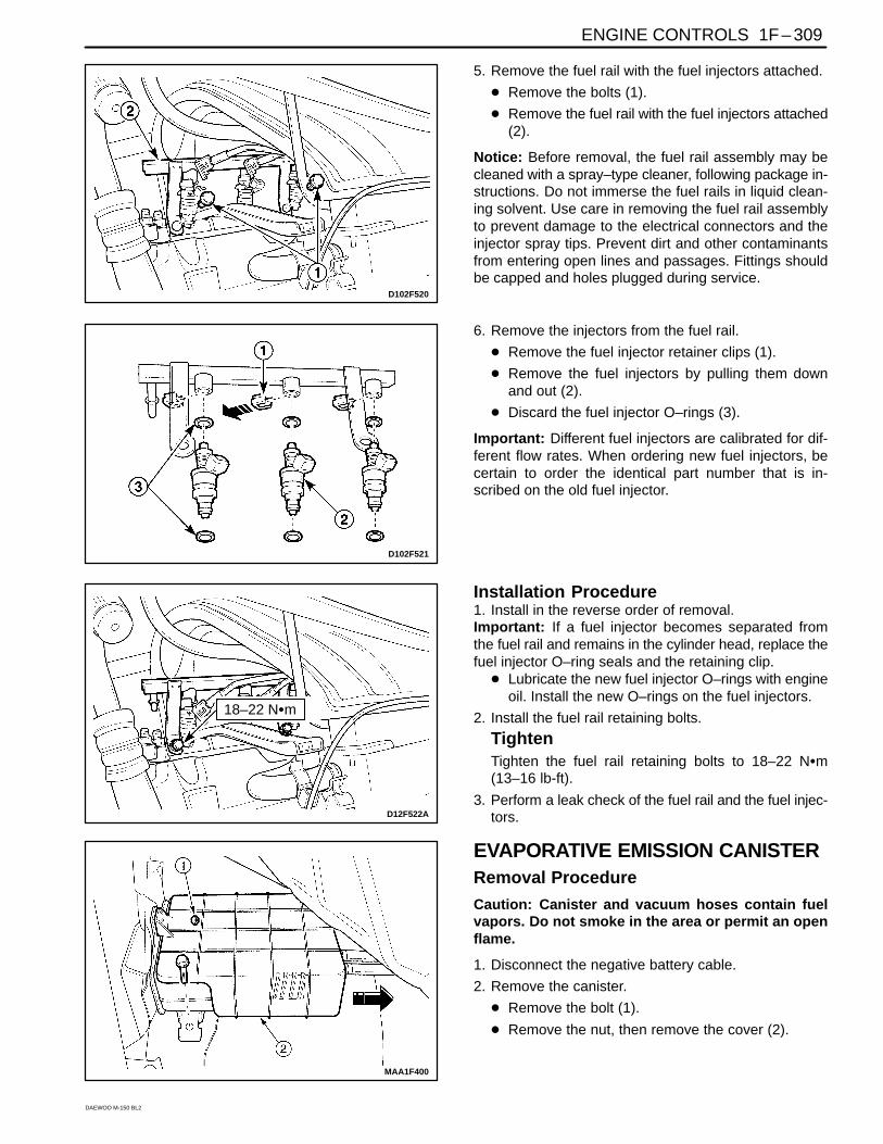
Installation Procedure1. Install in the reverse order of removal.
After the installation is complete, start the engineto prevent the vapor lock and check the hoses forleaks.
2. Install the fuel tank strap bolts.
TightenTighten the fuel tank strap bolts to 18–22 Nm (13–16lb-ft).
D102F519
D102F518
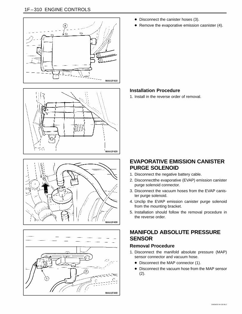
FUEL RAIL AND INJECTORSRemoval Procedure
Caution: The fuel system is under pressure. Toavoid fuel spillage and the risk of personal injury orfire, it is necessary to relieve the fuel system pres-sure before disconnecting the fuel lines.
1. Relieve the fuel system pressure. Refer to “Fuel Pump” in this section.
2. Remove the canister from the engine room. Refer to“Evaporative Emission Canister” in this section.
3. Disconnect the fuel inlet line (1).
4. Disconnect the fuel injector harness connectors (2).
ENGINE CONTROLS 1F – 309
DAEWOO M-150 BL2
D102F520
5. Remove the fuel rail with the fuel injectors attached.
Remove the bolts (1).
Remove the fuel rail with the fuel injectors attached(2).
Notice: Before removal, the fuel rail assembly may becleaned with a spray–type cleaner, following package in-structions. Do not immerse the fuel rails in liquid clean-ing solvent. Use care in removing the fuel rail assemblyto prevent damage to the electrical connectors and theinjector spray tips. Prevent dirt and other contaminantsfrom entering open lines and passages. Fittings shouldbe capped and holes plugged during service.
D102F521
6. Remove the injectors from the fuel rail.
Remove the fuel injector retainer clips (1).
Remove the fuel injectors by pulling them downand out (2).
Discard the fuel injector O–rings (3).
Important: Different fuel injectors are calibrated for dif-ferent flow rates. When ordering new fuel injectors, becertain to order the identical part number that is in-scribed on the old fuel injector.
D12F522A
18–22 Nm
Installation Procedure1. Install in the reverse order of removal.Important: If a fuel injector becomes separated fromthe fuel rail and remains in the cylinder head, replace thefuel injector O–ring seals and the retaining clip.
Lubricate the new fuel injector O–rings with engineoil. Install the new O–rings on the fuel injectors.
2. Install the fuel rail retaining bolts.
TightenTighten the fuel rail retaining bolts to 18–22 Nm(13–16 lb-ft).
3. Perform a leak check of the fuel rail and the fuel injec-tors.
MAA1F400
EVAPORATIVE EMISSION CANISTERRemoval Procedure
Caution: Canister and vacuum hoses contain fuelvapors. Do not smoke in the area or permit an openflame.
1. Disconnect the negative battery cable.
2. Remove the canister.
Remove the bolt (1).
Remove the nut, then remove the cover (2).
1F – 310 ENGINE CONTROLS
DAEWOO M-150 BL2
MAA1F410
Disconnect the canister hoses (3).
Remove the evaporative emission casnister (4).
MAA1F420
Installation Procedure1. Install in the reverse order of removal.
MAA1F430
EVAPORATIVE EMISSION CANISTERPURGE SOLENOID1. Disconnect the negative battery cable.
2. Disconnectthe evaporative (EVAP) emission canisterpurge solenoid connector.
3. Disconnect the vacuum hoses from the EVAP canis-ter purge solenoid.
4. Unclip the EVAP emission canister purge solenoidfrom the mounting bracket.
5. Installation should follow the removal procedure inthe reverse order.
MAA1F440
MANIFOLD ABSOLUTE PRESSURESENSORRemoval Procedure1. Disconnect the manifold absolute pressure (MAP)
sensor connector and vacuum hose.
Disconnect the MAP connector (1).
Disconnect the vacuum hose from the MAP sensor(2).
ENGINE CONTROLS 1F – 311
DAEWOO M-150 BL2
MAA1F450
2. Remove the MAP sensor.
Remove the bolts (1).
Remove the MAP sensor with bracket (2).
MAA1F460
Installatin Procedure1. Install in the reverse order of removal.
Inspect the MAP sensor vacuum hose for the tearand damages.
2. Install the MAP sensor with the bolts and nuts.
TightenTighten the MAP sensor bolts/nuts to 8–12 Nm(71–106 lb-in).
Tighten the MAP sensor bracket bolt to 8–12 Nm(71–106 lb-in).
D102F537
THROTTLE BODYRemoval Procedure1. Remove the air cleaner/resonator assembly and air
intake tube. Refer to Section 1B, SOHC Engine Me-chanical.
2. Drain the engine coolant. Refer to Section 1D, EngineCooling.
D102F538
3. Disconnect the throttle cable, the throttle positionsensor and the idle air control valve connectors.
Open the throttle valve (1).
Disconnect the throttle cable (2).
Disconnect the idle air control valve connector (3).
Disconnect the throttle position sensor connector(4).
1F – 312 ENGINE CONTROLS
DAEWOO M-150 BL2
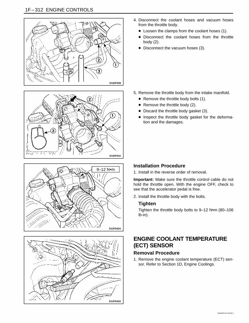
D102F539
4. Disconnect the coolant hoses and vacuum hosesfrom the throttle body.
Loosen the clamps from the coolant hoses (1).
Disconnect the coolant hoses from the throttlebody (2).
Disconnect the vacuum hoses (3).
D102F541
5. Remove the throttle body from the intake manifold.
Remove the throttle body bolts (1).
Remove the throttle body (2).
Discard the throttle body gasket (3).
Inspect the throttle body gasket for the deforma-tion and the damages.
9–12 Nm
D12F542A
Installation Procedure1. Install in the reverse order of removal.
Important: Make sure the throttle control cable do nothold the throttle open. With the engine OFF, check tosee that the accelerator pedal is free.
2. Install the throttle body with the bolts.
TightenTighten the throttle body bolts to 9–12 Nm (80–106lb-in).
D12F543A
ENGINE COOLANT TEMPERATURE(ECT) SENSORRemoval Procedure1. Remove the engine coolant temperature (ECT) sen-
sor. Refer to Section 1D, Engine Coolings.
ENGINE CONTROLS 1F – 313
DAEWOO M-150 BL2
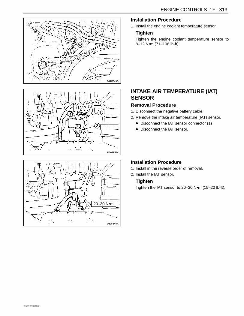
D12F543B
Installation Procedure1. Install the engine coolant temperature sensor.
TightenTighten the engine coolant temperature sensor to8–12 Nm (71–106 lb-ft).
D102F544
INTAKE AIR TEMPERATURE (IAT)SENSORRemoval Procedure1. Disconnect the negative battery cable.
2. Remove the intake air temperature (IAT) sensor.
Disconnect the IAT sensor connector (1)
Disconnect the IAT sensor.
20–30 Nm
D12F545A
Installation Procedure1. Install in the reverse order of removal.
2. Install the IAT sensor.
TightenTighten the IAT sensor to 20–30 Nm (15–22 lb-ft).
1F – 314 ENGINE CONTROLS
DAEWOO M-150 BL2
D102F546
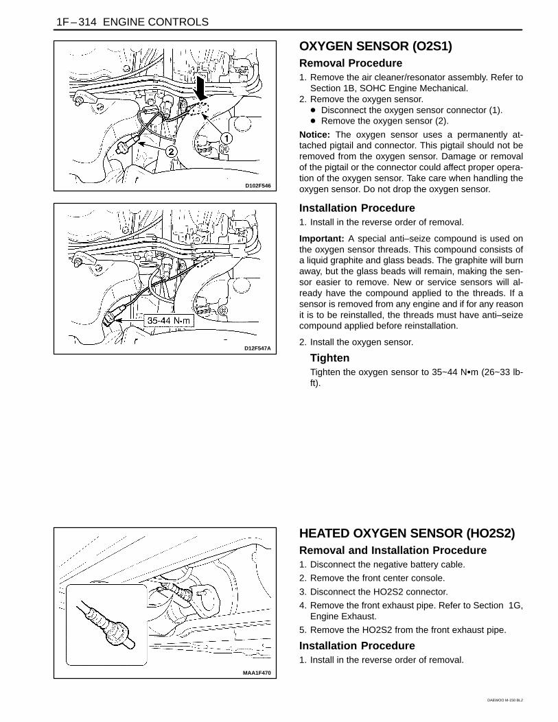
OXYGEN SENSOR (O2S1)Removal Procedure1. Remove the air cleaner/resonator assembly. Refer to
Section 1B, SOHC Engine Mechanical.2. Remove the oxygen sensor.
Disconnect the oxygen sensor connector (1). Remove the oxygen sensor (2).
Notice: The oxygen sensor uses a permanently at-tached pigtail and connector. This pigtail should not beremoved from the oxygen sensor. Damage or removalof the pigtail or the connector could affect proper opera-tion of the oxygen sensor. Take care when handling theoxygen sensor. Do not drop the oxygen sensor.
D12F547A
Installation Procedure1. Install in the reverse order of removal.
Important: A special anti–seize compound is used onthe oxygen sensor threads. This compound consists ofa liquid graphite and glass beads. The graphite will burnaway, but the glass beads will remain, making the sen-sor easier to remove. New or service sensors will al-ready have the compound applied to the threads. If asensor is removed from any engine and if for any reasonit is to be reinstalled, the threads must have anti–seizecompound applied before reinstallation.
2. Install the oxygen sensor.
TightenTighten the oxygen sensor to 35~44 Nm (26~33 lb-ft).
MAA1F470
HEATED OXYGEN SENSOR (HO2S2)Removal and Installation Procedure1. Disconnect the negative battery cable.
2. Remove the front center console.
3. Disconnect the HO2S2 connector.
4. Remove the front exhaust pipe. Refer to Section 1G,Engine Exhaust.
5. Remove the HO2S2 from the front exhaust pipe.
Installation Procedure1. Install in the reverse order of removal.
ENGINE CONTROLS 1F – 315
DAEWOO M-150 BL2
Important: A special anti–seize compound is used onthe oxygen sensor threads. This compound consists ofa liquid graphite and glass beads. The graphite will burnaway, but the glass beads will remain, making the sen-sor easier to remove. New or service sensors will al-ready have the compound applied to the threads. If asensor is removed from any engine and if for any reasonit is to be reinstalled, the threads must have anti–seizecompound applied before reinstallation.
2. Install the oxygen sensor.
TightenTighten the oxygen sensor to 35~44 Nm (26~33 lb-ft).
MAA1F480
EXHAUST GAS RECIRCULATIONVALVERemoval Procedure1. Disconnect the negative battery cable.
2. Remove the air cleaner assembly.
3. Disconnect the electric exhaust gas recirculation(EEGR) valve connector.
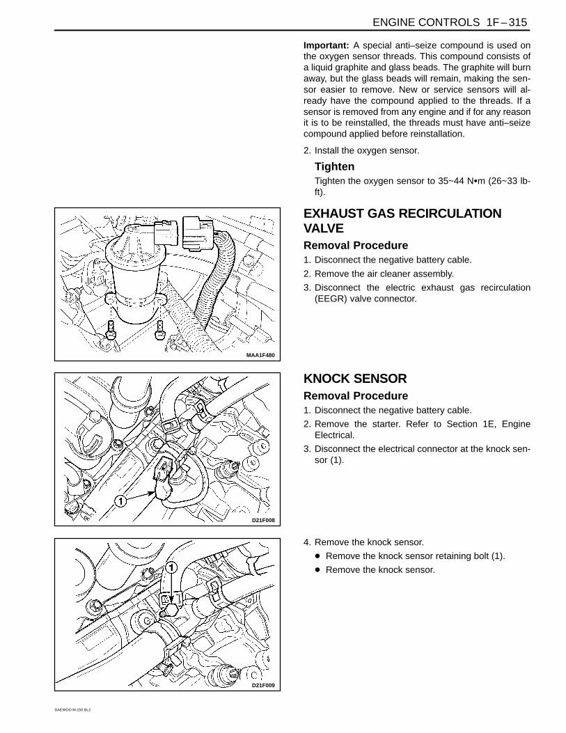
D21F008
KNOCK SENSORRemoval Procedure1. Disconnect the negative battery cable.
2. Remove the starter. Refer to Section 1E, EngineElectrical.
3. Disconnect the electrical connector at the knock sen-sor (1).
D21F009
4. Remove the knock sensor.
Remove the knock sensor retaining bolt (1).
Remove the knock sensor.
1F – 316 ENGINE CONTROLS
DAEWOO M-150 BL2
D21F010
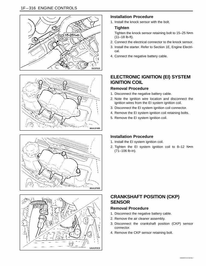
Installation Procedure1. Install the knock sensor with the bolt.
TightenTighten the knock sensor retaining bolt to 15–25 Nm(11–18 lb-ft).
2. Connect the electrical connector to the knock sensor.
3. Install the starter. Refer to Section 1E, Engine Electri-cal.
4. Connect the negative battery cable.
MAA1F490
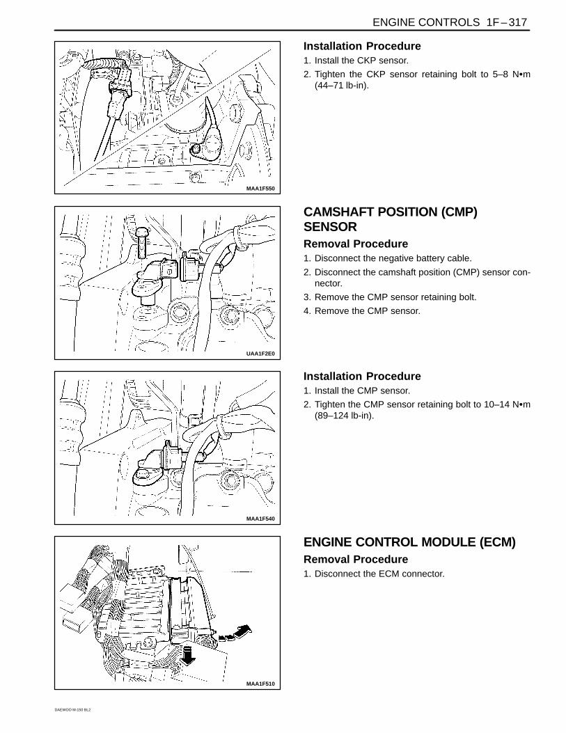
ELECTRONIC IGNITION (EI) SYSTEMIGNITION COILRemoval Procedure1. Disconnect the negative battery cable.
2. Note the ignition wire location and disconnect theignition wires from the EI system ignition coil.
3. Disconnect the EI system ignition coil connector.
4. Remove the EI system ignition coil retaining bolts.
5. Remove the EI system ignition coil.
MAA1F500
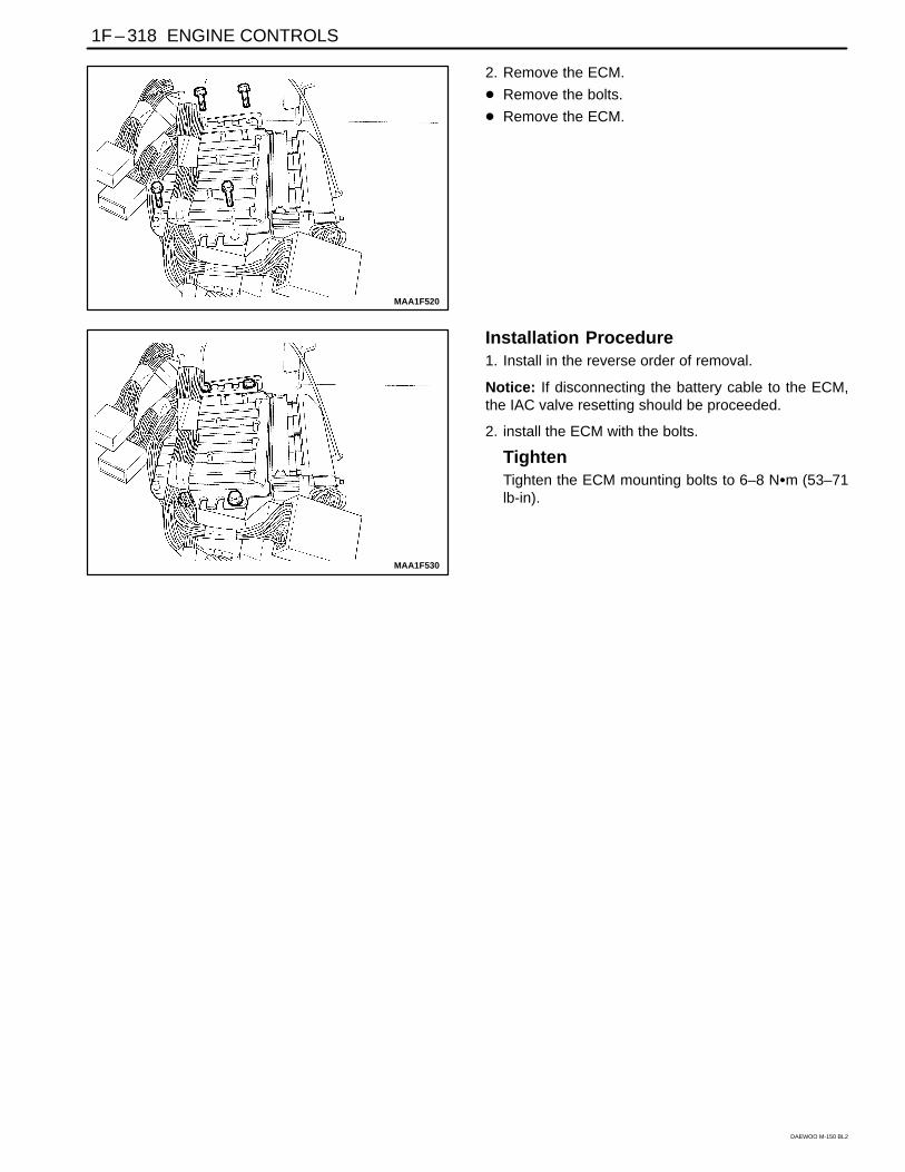
Installation Procedure1. Install the EI system ignition coil.
2. Tighten the EI system ignition coil to 8–12 Nm(71–106 lb-in).
UAA1F2C0
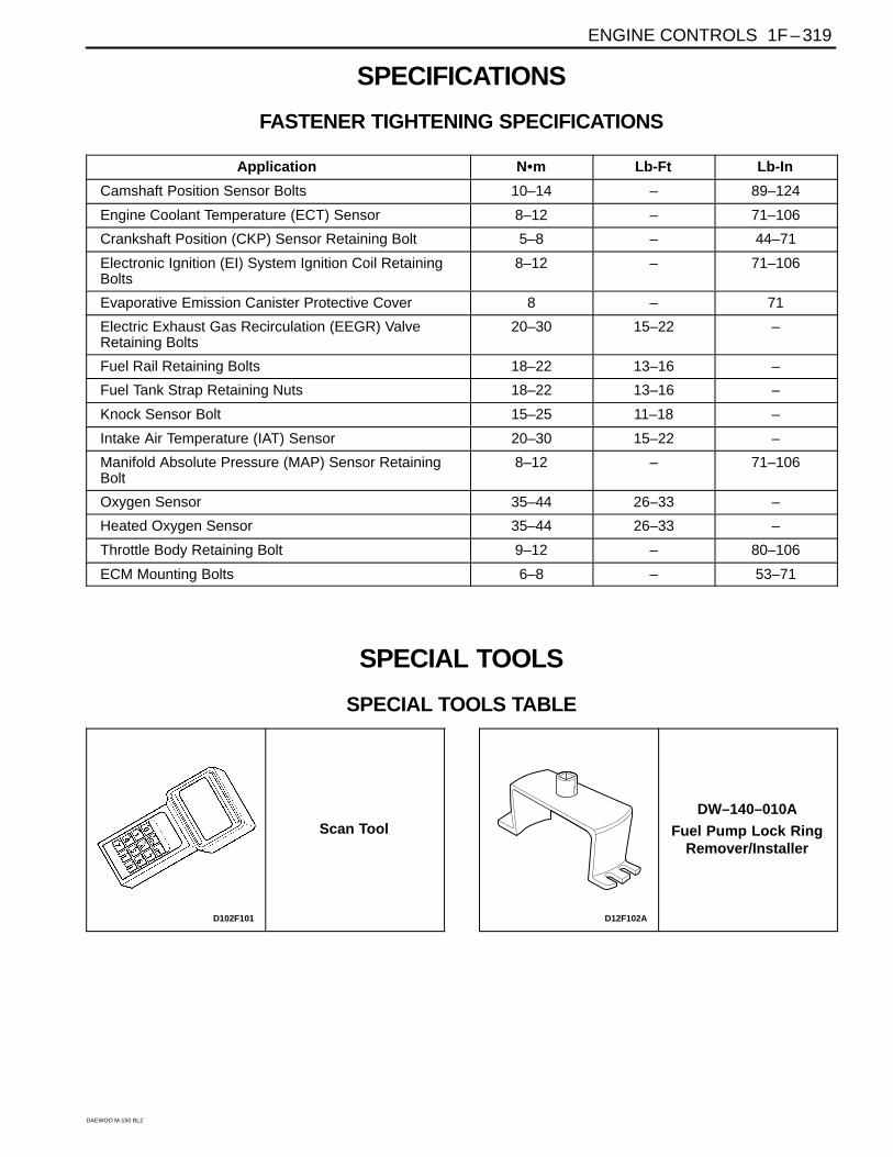
CRANKSHAFT POSITION (CKP)SENSORRemoval Procedure1. Disconnect the negative battery cable.
2. Remove the air cleaner assembly.
3. Disconnect the crankshaft position (CKP) sensorconnector.
4. Remove the CKP sensor retaining bolt.
ENGINE CONTROLS 1F – 317
DAEWOO M-150 BL2
MAA1F550
Installation Procedure1. Install the CKP sensor.
2. Tighten the CKP sensor retaining bolt to 5–8 Nm(44–71 lb-in).
UAA1F2E0
CAMSHAFT POSITION (CMP)SENSORRemoval Procedure1. Disconnect the negative battery cable.
2. Disconnect the camshaft position (CMP) sensor con-nector.
3. Remove the CMP sensor retaining bolt.
4. Remove the CMP sensor.
MAA1F540
Installation Procedure1. Install the CMP sensor.
2. Tighten the CMP sensor retaining bolt to 10–14 Nm(89–124 lb-in).
MAA1F510
ENGINE CONTROL MODULE (ECM)Removal Procedure1. Disconnect the ECM connector.
1F – 318 ENGINE CONTROLS
DAEWOO M-150 BL2
MAA1F520
2. Remove the ECM.
Remove the bolts.
Remove the ECM.
MAA1F530
Installation Procedure1. Install in the reverse order of removal.
Notice: If disconnecting the battery cable to the ECM,the IAC valve resetting should be proceeded.
2. install the ECM with the bolts.
TightenTighten the ECM mounting bolts to 6–8 Nm (53–71lb-in).
ENGINE CONTROLS 1F – 319
DAEWOO M-150 BL2
SPECIFICATIONS
FASTENER TIGHTENING SPECIFICATIONS
Application Nm Lb-Ft Lb-In
Camshaft Position Sensor Bolts 10–14 – 89–124
Engine Coolant Temperature (ECT) Sensor 8–12 – 71–106
Crankshaft Position (CKP) Sensor Retaining Bolt 5–8 – 44–71
Electronic Ignition (EI) System Ignition Coil RetainingBolts
8–12 – 71–106
Evaporative Emission Canister Protective Cover 8 – 71
Electric Exhaust Gas Recirculation (EEGR) ValveRetaining Bolts
20–30 15–22 –
Fuel Rail Retaining Bolts 18–22 13–16 –
Fuel Tank Strap Retaining Nuts 18–22 13–16 –
Knock Sensor Bolt 15–25 11–18 –
Intake Air Temperature (IAT) Sensor 20–30 15–22 –
Manifold Absolute Pressure (MAP) Sensor RetainingBolt
8–12 – 71–106
Oxygen Sensor 35–44 26–33 –
Heated Oxygen Sensor 35–44 26–33 –
Throttle Body Retaining Bolt 9–12 – 80–106
ECM Mounting Bolts 6–8 – 53–71
SPECIAL TOOLS
SPECIAL TOOLS TABLE
D102F101
Scan Tool
D12F102A
DW–140–010A
Fuel Pump Lock RingRemover/Installer
1F–
320 EN
GIN
E C
ON
TR
OLS
DA
EW
OO
M-150 B
L2
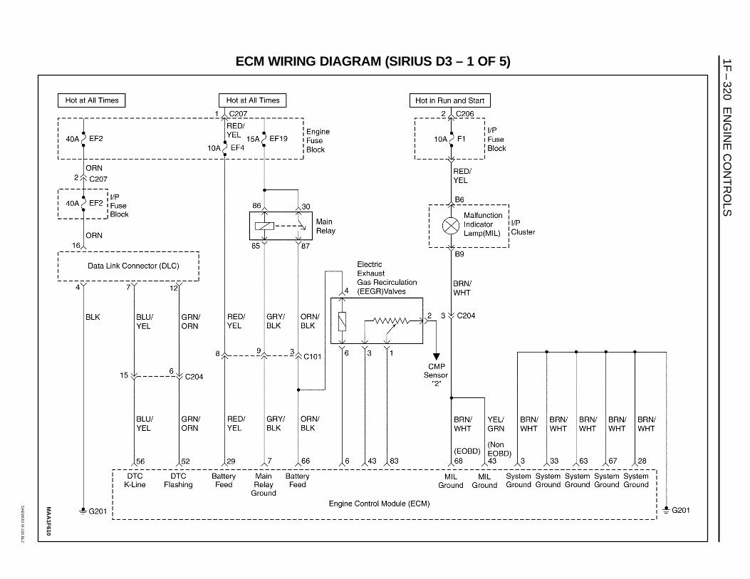
ECM WIRING DIAGRAM (SIRIUS D3 – 1 OF 5)
MA
A1F
610
EN
GIN
E C
ON
TR
OLS
1F–
321
DA
EW
OO
M-150 B
L2
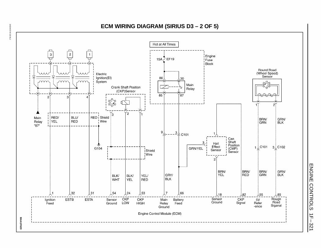
ECM WIRING DIAGRAM (SIRIUS D3 – 2 OF 5)
MA
A1F
620
1F–
322 EN
GIN
E C
ON
TR
OLS
DA
EW
OO
M-150 B
L2
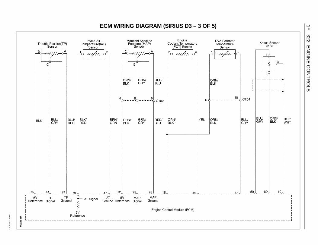
ECM WIRING DIAGRAM (SIRIUS D3 – 3 OF 5)
MA
AF
630
EN
GIN
E C
ON
TR
OLS
1F–
323
DA
EW
OO
M-150 B
L2
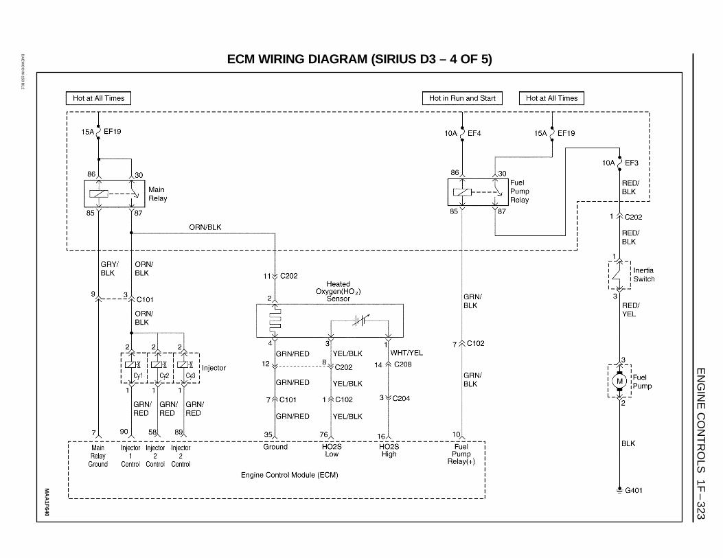
ECM WIRING DIAGRAM (SIRIUS D3 – 4 OF 5)
MA
A1F
640
1F–
324 EN
GIN
E C
ON
TR
OLS
DA
EW
OO
M-150 B
L2
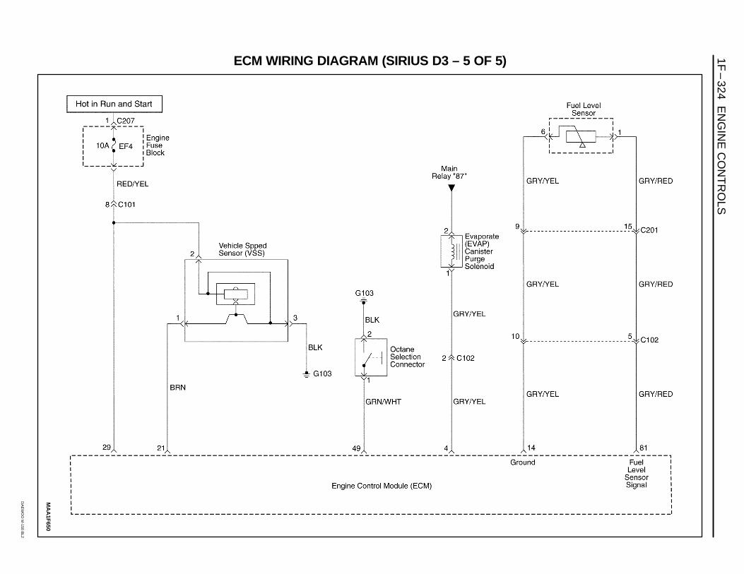
ECM WIRING DIAGRAM (SIRIUS D3 – 5 OF 5)
MA
A1F
650