Embed Size (px)
Citation preview

M2M 4G LTE Serial Modem MA-2060-4G Hardware Specifications
4G Lite 4G Serial Modem|MA-2060-4G
99 Station Rd Seven Hills NSW 2147 www.maxon.com.au | [email protected] P 02 8814 2300 | F 02 9630 0844
IntelimaxLITE 4G Hardware Specifications V1.00
2
T ABLE OF CONTENTS
TABLE OF CONTENTS ··················································································· 2
CONTACT INFORMATION··············································································· 3
RF EXPOSURE ELECTRICAL SAFETY COMPLIANCE ········································ 4
DISCLAIMERS ······························································································· 7
REVISION HISTORY ······················································································ 8
PRODUCT OVERVIEW ··················································································· 9
PRODUCT SPECIFICATIONS ········································································· 11
LED FUNCTIONALITY ··················································································· 14
MODEM CONNECTIONS ··············································································· 15
Mechanical Diagram ······················································································· 19
IntelimaxLITE 4G Hardware Specifications V1.00
3
CONT ACT INFORMAT ION
In keeping with RF Industries/Maxon's dedicated customer support policy, we encourage you to
contact us.
TECHNICAL:
Hours of Operation: Monday to Friday 8.30am to 5.00pm*
Telephone: +61 2 8814 2300
Facsimile: +61 2 9630 0844
Email: [email protected] * Public holidays excluded
SALES:
Hours of Operation: Monday to Friday 8.30am to 5.00pm*
Telephone: +61 2 8814 2300
Facsimile: +61 2 9630 0844
Email: [email protected] * Public holidays excluded
WEBSITE: www.maxon.com.au
ADDRESS:
RF Industries Pty Ltd
99 Station Road
Seven Hills NSW 2147 Australia
POSTAL ADDRESS
RF Industries Pty Ltd
Locked Bag 2007
Seven Hills NSW 1730 Australia
IntelimaxLITE 4G Hardware Specifications V1.00
4
RF EX POSURE E LECTR ICAL SAFETY
COM PL IANCE
The use of this device in any other type of host configuration may not comply with the RF exposure
requirements and should be avoided. During operation, a 20 cm separation distance should be
maintained between the antenna, whether extended or retracted, and the user’s/bystander’s
body (excluding hands, wrists, feet, and ankles) to ensure RF exposure compliance. The modem is
not designed for, nor intended to be, used in applications within 20 cm (8 inches) of the body of
the user. Continued compliance of the equipment relies upon it being used with an AS/NZS 60950.1
approved SELV power supply.
Caution
Change or modification without the express consent of RF Industries Pty. Ltd. voids the user’s
authority to use the equipment. These limits are designed to provide reasonable protection against
harmful interference in an appropriate installation. The modem is a transmitting device with similar
output power to a mobile phone. This equipment generates, uses, and can radiate radio
frequency energy and, if not used in accordance with instructions, can cause harmful radiation to
radio communication. The modem is approved for use with the antenna: ANT-SMA. Unauthorized
antennas, modifications, or attachments could impair call quality, damage the device, or result in
violation of RF exposure regulations.
However, there is no guarantee that interference will not occur in a particular installation. If the
equipment does cause harmful interference in radio and television reception, which can be
determined by turning the equipment on and off, the user is encouraged to try to correct the
interference by one or more of the following measures:
Re-orient or relocate the receiving radio or TV antenna
Increase the separation distance between the equipment and the receiver
Contact RF Industries Maxon product Technical Support for assistance.
General Safety
RF Interference Issues: Avoid possible radio frequency (RF) interference by carefully following safety
guidelines below:
IntelimaxLITE 4G Hardware Specifications V1.00
5
Switch OFF the modem when in an aircraft. The use of cellular telephones in aircraft is illegal.
It may endanger the operation of the aircraft and/or disrupt the cellular network. Failure to
observe this instruction may lead to suspension or denial of cellular services to the offender,
legal action, or both.
Switch OFF the modem in the vicinity of gasoline or diesel fuel pumps or before filling a
vehicle with fuel.
Switch OFF the modem in hospitals and any other place where medical equipment may be
in use.
Respect restrictions on the use of radio equipment in fuel depots, chemical plants, or in
areas of blasting operations.
There may be a hazard associated with the operation of your Modem in the vicinity of
inadequately protected personal medical devices such as hearing aids and pacemakers.
Please consult the manufacturers of the medical device to determine if it is adequately
protected.
Operation of the modem in the vicinity of other electronic equipment may cause
interference if the equipment is inadequately protected. Observe any warning signs and
manufacturers’ recommendations.
The modem contains sensitive electronic circuitry. Do not expose the modem to any liquids,
high temperatures or shock. The modem is not waterproof. Please keep it dry and store it in
a cool, dry place.
Only use original accessories or accessories that are authorized by the manufacturer. Using
unauthorized accessories may affect your modem’s performance, damage your modem
and violate related national regulations.
Always handle the modem with care. There are no user serviceable parts inside the modem.
Unauthorised dismantling or repair of the modem will void the warranty.
The product needs to be supplied by a limited power source or the power
supply provided. Otherwise, safety will not be ensured.
Do not fixed the product in an open area where it is liable to lightning strike
hazard.
Vehicle Safety
Do not use the modem while driving.
Respect national regulations on the use of cellular telephones in vehicles. Road safety
always comes first.
If incorrectly installed in a vehicle, the operation of the modem could interfere with the
IntelimaxLITE 4G Hardware Specifications V1.00
6
correct functioning of vehicle electronics. To avoid such problems, be sure that the
installation has been performed by qualified personnel.
Verification of the protection of vehicle electronics should be part of the installation.
Note: The user is cautioned that changes or modifications not expressly approved by RF Industries
could void the warrantee.
Potentially Unsafe Areas
Posted Facilities: Turn off this device in any facility or area when posted notices require you to do so.
Blasting Areas: Turn off your device where blasting is in progress. Observe restrictions and follow any
regulations or rules.
Potentially Explosive Atmospheres: Turn off your device when you are in any area with a potentially
explosive atmosphere. Obey all signs and instructions. Sparks in such areas could cause an
explosion or fire, resulting in bodily injury or death.
Areas with a potentially explosive atmosphere are often but not always clearly marked. They
include:
Fuelling areas such as gas or petrol stations
Below deck on boats
Transfer or storage facilities for fuel or chemicals
Vehicles using liquefied petroleum gas, such as propane or butane
Areas when the air contains chemicals or particles such as grain, dust or metal powders
Avoid using the modem in areas that emit electromagnetic waves or enclosed metallic
structures e.g. lifts.
Any other area where you would normally be ad
IntelimaxLITE 4G Hardware Specifications V1.00
7
DISCL A IMERS
All data and information contained in or disclosed by this document are confidential and
proprietary information of RF Industries, and all rights therein are expressly reserved. By accepting
this material, the recipient agrees that this material and the information contained therein are held
in confidence and in trust and will not be used, copied, reproduced in whole or in part, nor its
contents revealed in any manner to others without the express written permission of RF Industries.
This information provided in this document is provided on an “as is” basis.
In no event will RF Industries be liable for any damages arising directly or indirectly from any use of
information contained in this document. Information in this document is preliminary and subjected
to change without any notice.
Life support – This product is not designed for use in life support appliances or systems where
malfunction of these products can reasonably be expected to result in personal injury.
RF Industries customers using or selling these products for use in such applications do so at their own
risk and agree to fully indemnify RF Industries for any damages resulting from such application.
Right to make change - RF Industries reserves the right to make changes, without notice, in the
products, including circuits and software, described or contained herein in order to improve design
and/or performance.
Some features outlined in this manual may require an updated firmware version and/or GUI version
to work. Please contact RF Industries for more information.
exclusive property of Maxon Australia. Not to be distributed or divulged without prior written
agreement.
Padstow NSW 2211 Australia URL: www.maxon.com.au
IntelimaxLITE 4G Hardware Specifications V1.00
8
REV IS ION H IS TORY
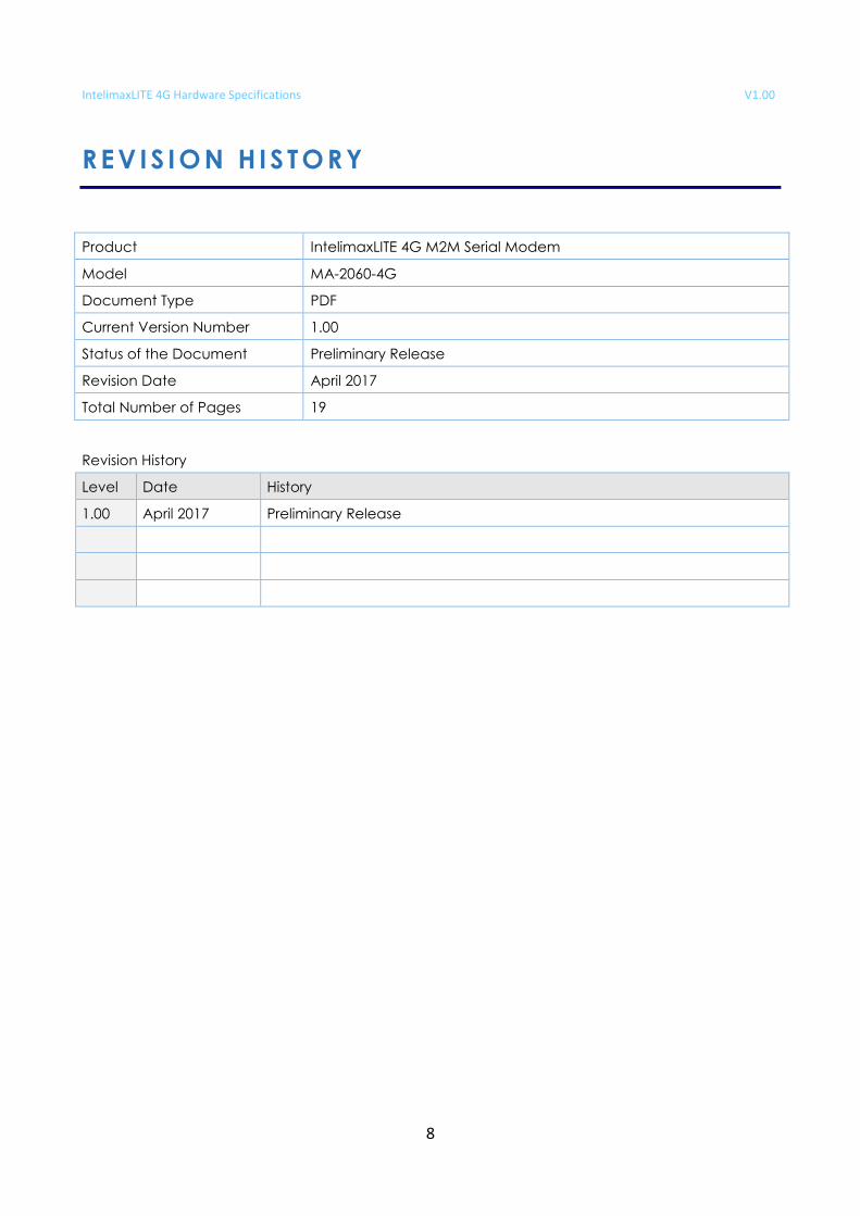
Product IntelimaxLITE 4G M2M Serial Modem
Model MA-2060-4G
Document Type PDF
Current Version Number 1.00
Status of the Document Preliminary Release
Revision Date April 2017
Total Number of Pages 19
Revision History
Level Date History
1.00 April 2017 Preliminary Release
IntelimaxLITE 4G Hardware Specifications V1.00
9
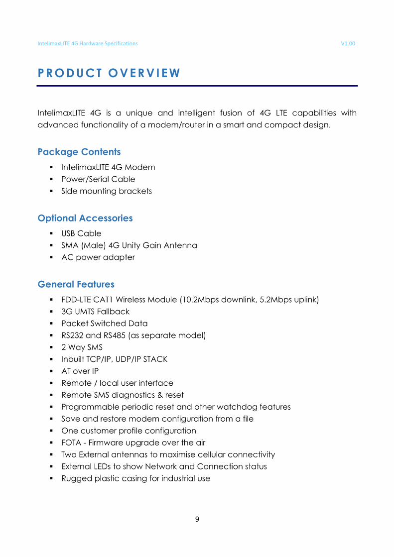
PRODUCT OVERV IEW
IntelimaxLITE 4G is a unique and intelligent fusion of 4G LTE capabilities with
advanced functionality of a modem/router in a smart and compact design.
Package Contents
IntelimaxLITE 4G Modem
Power/Serial Cable
Side mounting brackets
Optional Accessories
USB Cable
SMA (Male) 4G Unity Gain Antenna
AC power adapter
General Features
FDD-LTE CAT1 Wireless Module (10.2Mbps downlink, 5.2Mbps uplink)
3G UMTS Fallback
Packet Switched Data
RS232 and RS485 (as separate model)
2 Way SMS
Inbuilt TCP/IP, UDP/IP STACK
AT over IP
Remote / local user interface
Remote SMS diagnostics & reset
Programmable periodic reset and other watchdog features
Save and restore modem configuration from a file
One customer profile configuration
FOTA - Firmware upgrade over the air
Two External antennas to maximise cellular connectivity
External LEDs to show Network and Connection status
Rugged plastic casing for industrial use
IntelimaxLITE 4G Hardware Specifications V1.00
10
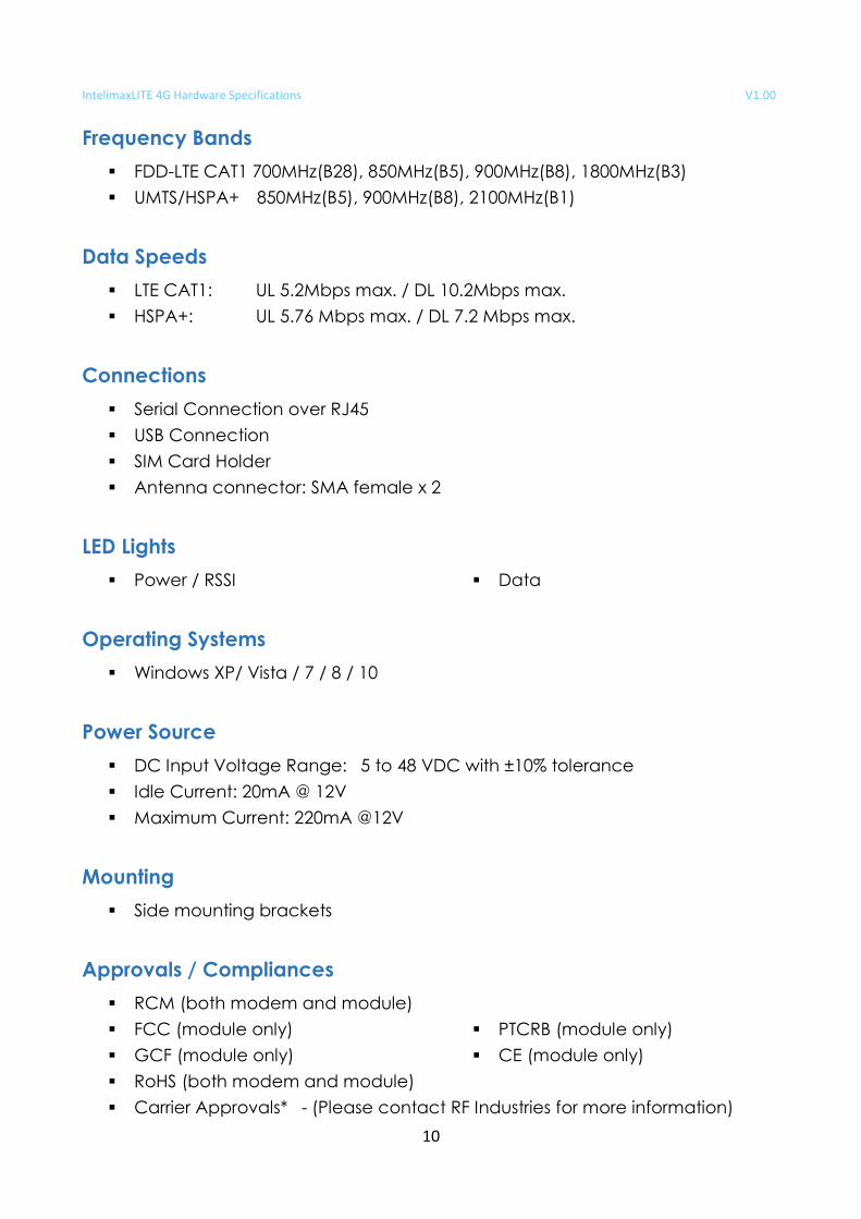
Frequency Bands
FDD-LTE CAT1 700MHz(B28), 850MHz(B5), 900MHz(B8), 1800MHz(B3)
UMTS/HSPA+ 850MHz(B5), 900MHz(B8), 2100MHz(B1)
Data Speeds
LTE CAT1: UL 5.2Mbps max. / DL 10.2Mbps max.
HSPA+: UL 5.76 Mbps max. / DL 7.2 Mbps max.
Connections
Serial Connection over RJ45
USB Connection
SIM Card Holder
Antenna connector: SMA female x 2
LED Lights
Power / RSSI Data
Operating Systems
Windows XP/ Vista / 7 / 8 / 10
Power Source
DC Input Voltage Range: 5 to 48 VDC with ±10% tolerance
Idle Current: 20mA @ 12V
Maximum Current: 220mA @12V
Mounting
Side mounting brackets
Approvals / Compliances
RCM (both modem and module)
FCC (module only)
GCF (module only)
PTCRB (module only)
CE (module only)
RoHS (both modem and module)
Carrier Approvals* - (Please contact RF Industries for more information)
IntelimaxLITE 4G Hardware Specifications V1.00
11
PRODUCT SPECIF ICAT IONS
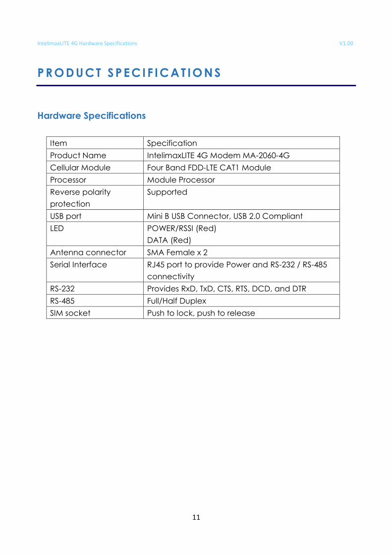
Hardware Specifications
Item Specification
Product Name IntelimaxLITE 4G Modem MA-2060-4G
Cellular Module Four Band FDD-LTE CAT1 Module
Processor Module Processor
Reverse polarity
protection
Supported
USB port Mini B USB Connector, USB 2.0 Compliant
LED POWER/RSSI (Red)
DATA (Red)
Antenna connector SMA Female x 2
Serial Interface RJ45 port to provide Power and RS-232 / RS-485
connectivity
RS-232 Provides RxD, TxD, CTS, RTS, DCD, and DTR
RS-485 Full/Half Duplex
SIM socket Push to lock, push to release
IntelimaxLITE 4G Hardware Specifications V1.00
12
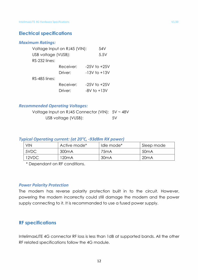
Electrical specifications
Maximum Ratings:
Voltage Input on RJ45 (VIN): 54V
USB voltage (VUSB): 5.5V
RS-232 lines:
Receiver: -25V to +25V
Driver: -13V to +13V
RS-485 lines:
Receiver: -25V to +25V
Driver: -8V to +13V
Recommended Operating Voltages:
Voltage Input on RJ45 Connector (VIN): 5V ~ 48V
USB voltage (VUSB): 5V
Typical Operating current: (at 20°C, -93dBm RX power)
VIN Active mode* Idle mode* Sleep mode
5VDC 300mA 75mA 50mA
12VDC 120mA 30mA 20mA
* Dependant on RF conditions.
Power Polarity Protection
The modem has reverse polarity protection built in to the circuit. However,
powering the modem incorrectly could still damage the modem and the power
supply connecting to it. It is recommanded to use a fused power supply.
RF specifications
IntelimaxLITE 4G connector RF loss is less than 1dB at supported bands. All the other
RF related specifications follow the 4G module.
IntelimaxLITE 4G Hardware Specifications V1.00
13
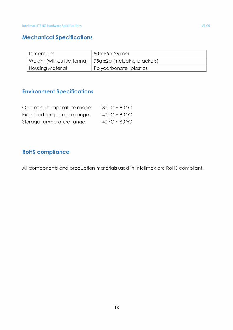
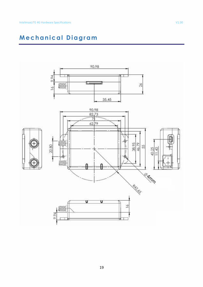
Mechanical Specifications
Dimensions 80 x 55 x 26 mm
Weight (without Antenna) 75g ±2g (Including brackets)
Housing Material Polycarbonate (plastics)
Environment Specifications
Operating temperature range: -30 °C ~ 60 °C
Extended temperature range: -40 °C ~ 60 °C
Storage temperature range: -40 °C ~ 60 °C
RoHS compliance
All components and production materials used in Intelimax are RoHS compliant.
IntelimaxLITE 4G Hardware Specifications V1.00
14
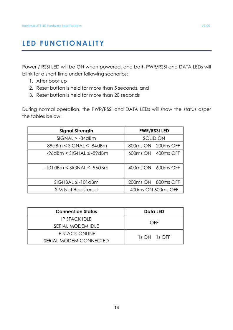
L ED FUNCT IONAL I T Y
Power / RSSI LED will be ON when powered, and both PWR/RSSI and DATA LEDs will
blink for a short time under following scenarios:
1. After boot up
2. Reset button is held for more than 5 seconds, and
3. Reset button is held for more than 20 seconds
During normal operation, the PWR/RSSI and DATA LEDs will show the status asper
the tables below:
Signal Strength PWR/RSSI LED
SIGNAL > -84dBm SOLID ON
-89dBm < SIGNAL ≤ -84dBm 800ms ON 200ms OFF
-96dBm < SIGNAL ≤ -89dBm 600ms ON 400ms OFF
-101dBm < SIGNAL ≤ -96dBm 400ms ON 600ms OFF
SIGNBAL ≤ -101dBm 200ms ON 800ms OFF
SIM Not Registered 400ms ON 600ms OFF
Connection Status Data LED
IP STACK IDLE
SERIAL MODEM IDLE OFF
IP STACK ONLINE
SERIAL MODEM CONNECTED 1s ON 1s OFF
IntelimaxLITE 4G Hardware Specifications V1.00
15
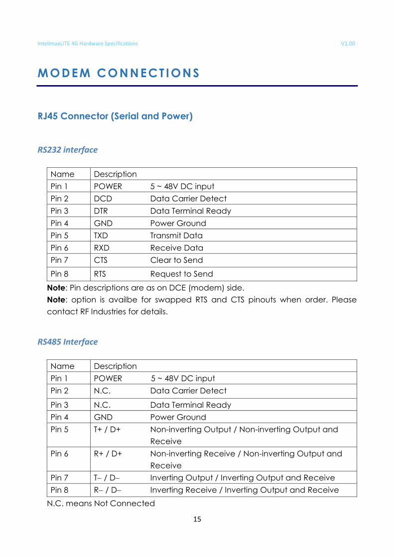
MODEM CONNECT IONS
RJ45 Connector (Serial and Power)
RS232 interface
Name Description
Pin 1 POWER 5 ~ 48V DC input
Pin 2 DCD Data Carrier Detect
Pin 3 DTR Data Terminal Ready
Pin 4 GND Power Ground
Pin 5 TXD Transmit Data
Pin 6 RXD Receive Data
Pin 7 CTS Clear to Send
Pin 8 RTS Request to Send
Note: Pin descriptions are as on DCE (modem) side.
Note: option is availbe for swapped RTS and CTS pinouts when order. Please
contact RF Industries for details.
RS485 Interface
Name Description
Pin 1 POWER 5 ~ 48V DC input
Pin 2 N.C. Data Carrier Detect
Pin 3 N.C. Data Terminal Ready
Pin 4 GND Power Ground
Pin 5
T+ / D+ Non-inverting Output / Non-inverting Output and
Receive
Pin 6
R+ / D+ Non-inverting Receive / Non-inverting Output and
Receive
Pin 7 T / D Inverting Output / Inverting Output and Receive
Pin 8 R / D Inverting Receive / Inverting Output and Receive
N.C. means Not Connected
IntelimaxLITE 4G Hardware Specifications V1.00
16
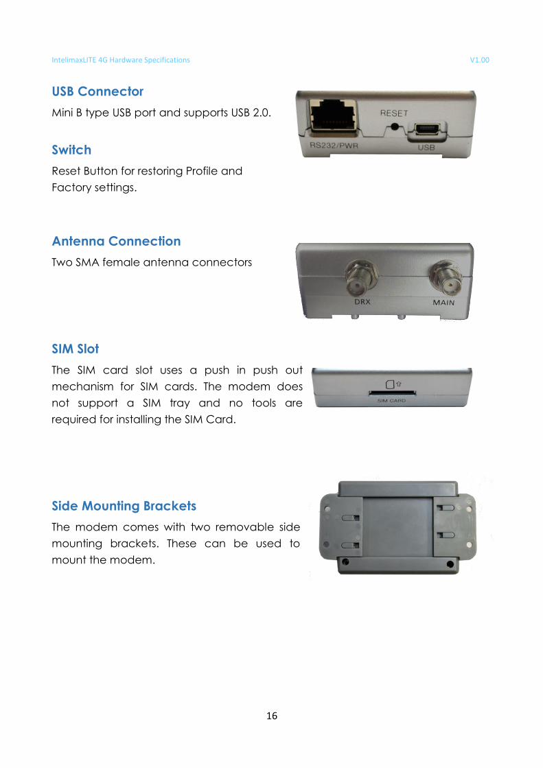
USB Connector
Mini B type USB port and supports USB 2.0.
Switch
Reset Button for restoring Profile and
Factory settings.
Antenna Connection
Two SMA female antenna connectors
SIM Slot
The SIM card slot uses a push in push out
mechanism for SIM cards. The modem does
not support a SIM tray and no tools are
required for installing the SIM Card.
Side Mounting Brackets
The modem comes with two removable side
mounting brackets. These can be used to
mount the modem.
IntelimaxLITE 4G Hardware Specifications V1.00
17
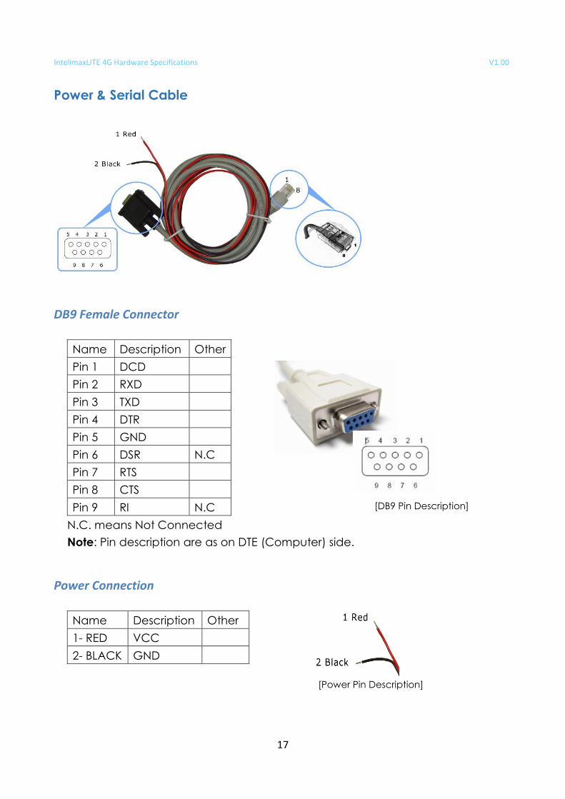
Power & Serial Cable
DB9 Female Connector
Name Description Other
Pin 1 DCD
Pin 2 RXD
Pin 3 TXD
Pin 4 DTR
Pin 5 GND
Pin 6 DSR N.C
Pin 7 RTS
Pin 8 CTS
Pin 9 RI N.C
N.C. means Not Connected
Note: Pin description are as on DTE (Computer) side.
Power Connection
Name Description Other
1- RED VCC
2- BLACK GND
[DB9 Pin Description]
[Power Pin Description]
IntelimaxLITE 4G Hardware Specifications V1.00
18
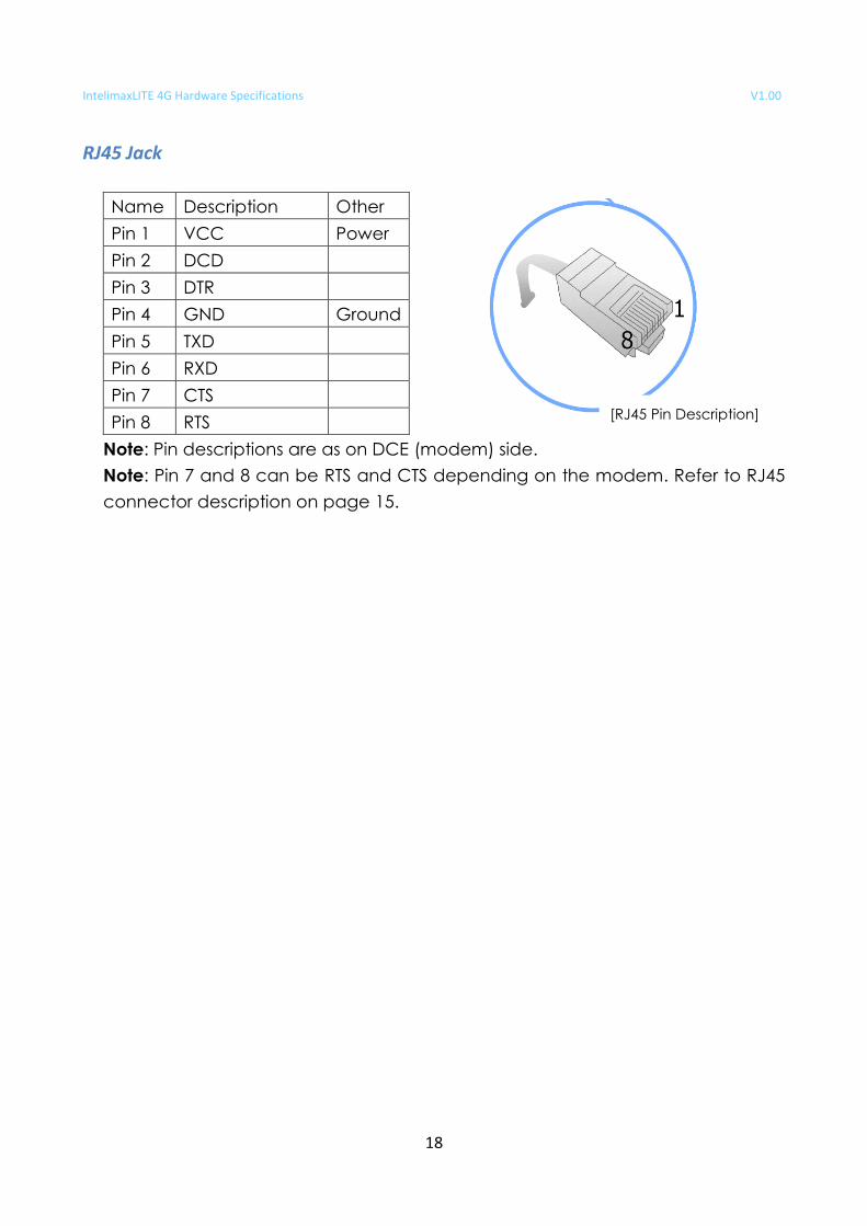
RJ45 Jack
Name Description Other
Pin 1 VCC Power
Pin 2 DCD
Pin 3 DTR
Pin 4 GND Ground
Pin 5 TXD
Pin 6 RXD
Pin 7 CTS
Pin 8 RTS
Note: Pin descriptions are as on DCE (modem) side.
Note: Pin 7 and 8 can be RTS and CTS depending on the modem. Refer to RJ45
connector description on page 15.
[RJ45 Pin Description]
IntelimaxLITE 4G Hardware Specifications V1.00
19
M e c han ica l D iag ram