Embed Size (px)
Citation preview
E x c e l l e n c e o n B o a rdE x c e l l e n c e o n B o a rd
M25Project Guide • Propulsion
m
Introduction
Caterpillar Motoren GmbH & Co. KGP. O. Box, D-24157 KielGermanyPhone +49 431 3995-01Telefax +49 431 3995-2193
Issue April 2004
Information for the user of this project guide
The project information contained in the following is not binding, since technical data of products mayespecially change due to product development and customer requests. Caterpillar Motoren reservesthe right to modify and amend data at any time. Any liability for accuracy of information providedherein is excluded.
Binding determination of data is made by means of the Technical Specification and such other agree-ments as may be entered into in connection with the order. We will supply further binding data, draw-ings, diagrams, electrical drawings, etc. in connection with a corresponding order.
This edition supersedes the previous edition of this project guide.
Major revisions of issue September 2002 are
- Uprating to 317/330 kW/cyl.- Technical data revised- DICARE revised
All rights reserved. Reproduction or copying only with our prior written consent.
m
m
Page
1. Engine description 1 - 2 2. General data and outputs 3 - 4 3. Restrictions for low load operation 5
4. Propeller operation 6 - 8 5. Technical data 9 - 10 6. Engine dimensions 11 - 18 7. Space requirement for dismantling of charge air cooler
and turbocharger cartridge 19 8. Maintenance platform 20
9. System connections 2110. Fuel oil system 22 - 3511. Lubricating oil system 36 - 4512. Cooling water system 46 - 5313. Reference values for flow velocities in pipes 5414. Flow velocities in pipes 5515. Starting air system 56 - 57
16. Combustion air system 5817. Exhaust system 59 - 6518. Air borne sound power level 6619. Foundation 67 - 7320. Resilient mounting 7421. Power transmission 75 - 78
22. Data for torsional vibration calculation 7923. Control and monitoring system 80 - 9824. Diagnostic system DICARE 99 - 10025. Diesel engine management system DIMOS 10126. Standard acceptance test run 10227. EIAPP certificate 103
28. Painting/Preservation 104 - 10529. Lifting of engines 10630. Engine parts 107
Contents
m
1
1. Engine description
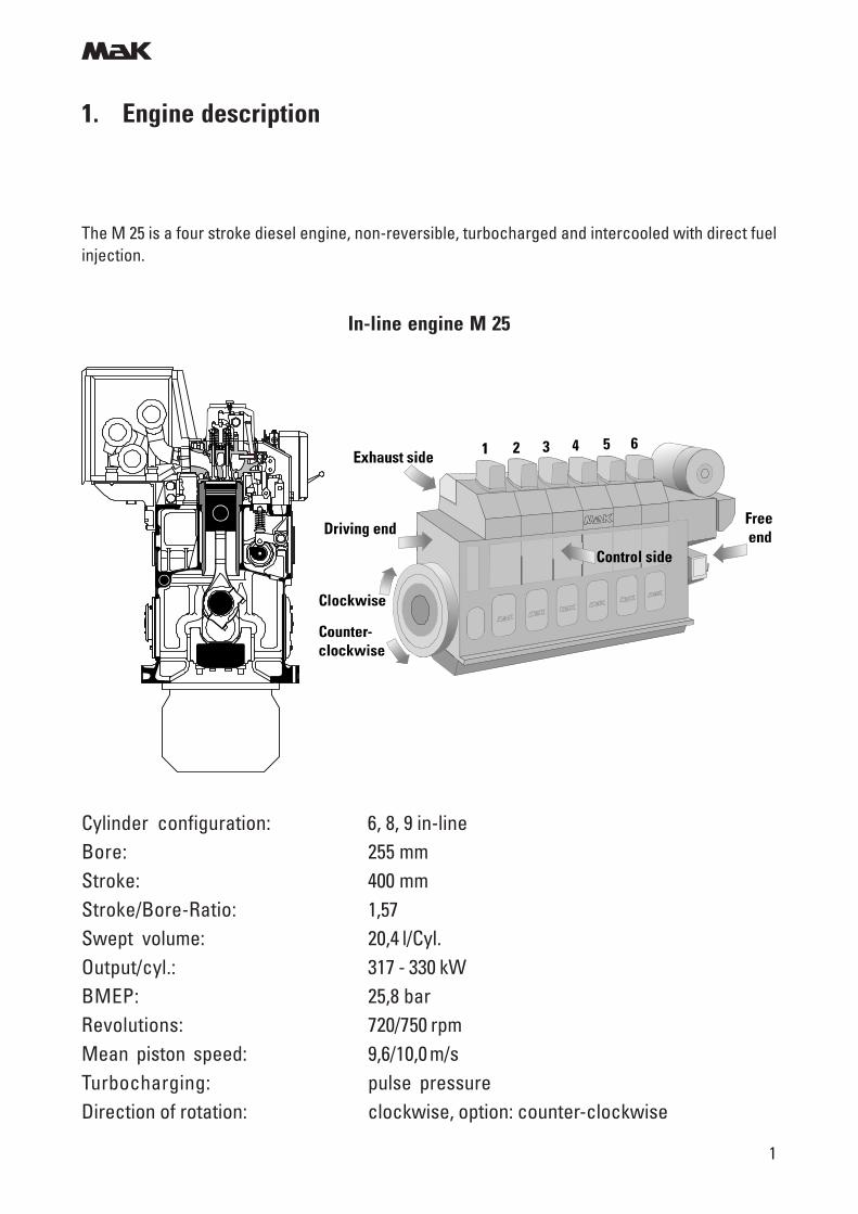
The M 25 is a four stroke diesel engine, non-reversible, turbocharged and intercooled with direct fuelinjection.
In-line engine M 25
Cylinder configuration: 6, 8, 9 in-lineBore: 255 mmStroke: 400 mmStroke/Bore-Ratio: 1,57Swept volume: 20,4 l/Cyl.Output/cyl.: 317 - 330 kWBMEP: 25,8 barRevolutions: 720/750 rpmMean piston speed: 9,6/10,0 m/sTurbocharging: pulse pressureDirection of rotation: clockwise, option: counter-clockwise
m
2
1. Engine description
Engine design
- Designed for heavy fuel operation up to 700 cst./50 °C, fuel grade acc. to CIMAC H55 K55, ISO 8217,1996 (E), ISO-F-RMH55 RMK55.
- 1-piece dry engine block made of nodular cast iron. It incorporates the crankshaft bearing, cam-shaft bearing, charge air receiver, vibration damper housing and gear drive housing.
- Underslung crankshaft with corrosion resistant main and big end bearing shells.
- Natural hardened liners, centrifugally casted, with calibration insert.
- Composite type pistons with steel crown and nodular cast iron skirt.
- Piston ring set consisting of 2 chromium plated compression rings, first ring with chrom-ceramiclayer and 1 chromium plated oil scraper ring. All ring grooves are hardened and located in thesteel crown.
- 2-piece connecting rod, fully machined, obliquely split with serrated joint.
- Cylinder head made of nodular cast iron with 2 inlet and 2 exhaust valves with valve rotators.Direct cooled exhaust valve seats.
- Camshaft made of sections per cylinder allowing a removal of the pieces sideways.
- Turbocharger supplied with inboard plain bearings lubricated by engine lubricating oil.
- 2-stage fresh water cooling system with 2-stage charge air cooler.
- Nozzle cooling for heavy fuel operation with engine lubricating oil.
m
3
2. General data and outputs
Output definition
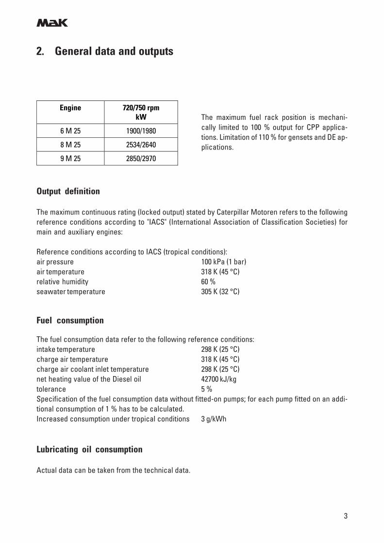
The maximum continuous rating (locked output) stated by Caterpillar Motoren refers to the followingreference conditions according to "IACS" (International Association of Classification Societies) formain and auxiliary engines:
Reference conditions according to IACS (tropical conditions):air pressure 100 kPa (1 bar)air temperature 318 K (45 °C)relative humidity 60 %seawater temperature 305 K (32 °C)
Fuel consumption
The fuel consumption data refer to the following reference conditions:intake temperature 298 K (25 °C)charge air temperature 318 K (45 °C)charge air coolant inlet temperature 298 K (25 °C)net heating value of the Diesel oil 42700 kJ/kgtolerance 5 %Specification of the fuel consumption data without fitted-on pumps; for each pump fitted on an addi-tional consumption of 1 % has to be calculated.Increased consumption under tropical conditions 3 g/kWh
Lubricating oil consumption
Actual data can be taken from the technical data.
Engine 720/750 rpm kW
6 M 25 1900/1980
8 M 25 2534/2640
9 M 25 2850/2970
The maximum fuel rack position is mechani-cally limited to 100 % output for CPP applica-tions. Limitation of 110 % for gensets and DE ap-plications.
m
4
Nitrogen oxide emissions (NOx-values)
NOx-limit values according IMO-regulations: 12,1 g/kWh (n = 720 rpm)12,0 g/kWh (n = 750 rpm)
The NOx value will remain below the IMO limit.
Emergency operation without turbocharger
Emergency operation is permissible only with MDO and up to approx. 20 % of the MCR.
General installation aspect:
Inclination angles of ships at which engine running must be possible:
Heel to each side: 15°Rolling to each side: + 22,5°Trim by head and stern: 5°Pitching: + 7,5°
2. General data and outputs
m
5
3. Restrictions for low load operation
The engine can be started, stopped and run on heavy fuel oil under all operating conditions.
The HFO system of the engine remains in operation and keeps the HFO at injection viscosity. The tem-perature of the engine injection system is maintained by circulating hot HFO and heat losses are com-pensated.
The lube oil treatment system (lube oil separator) remains in operation, the lube oil is separated con-tinuously.
The operating temperature of the engine cooling water is maintained by the cooling water preheater.
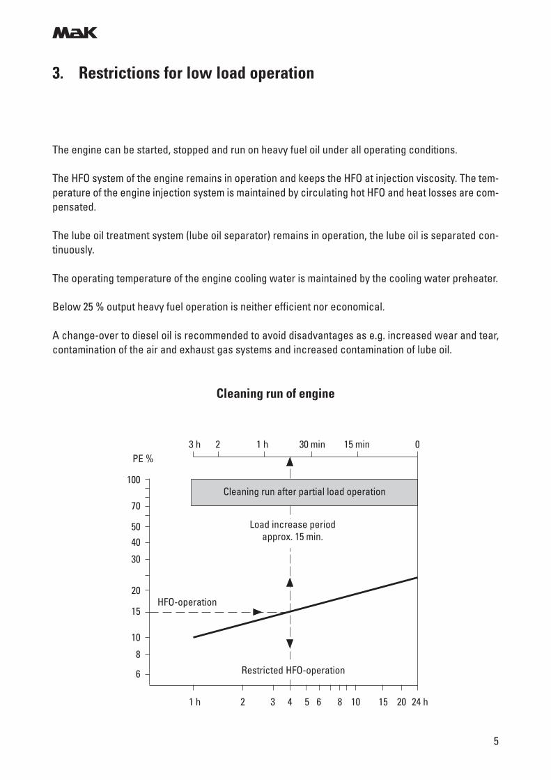
Below 25 % output heavy fuel operation is neither efficient nor economical.
A change-over to diesel oil is recommended to avoid disadvantages as e.g. increased wear and tear,contamination of the air and exhaust gas systems and increased contamination of lube oil.
Cleaning run of engine
1 h 2 3 4 5 6 8 10 15 20 24 h
PE %
100
70
5040
30
20
15
10
8
6
HFO-operation
3 h 2 1 h 30 min 15 min 0
Cleaning run after partial load operation
Load increase periodapprox. 15 min.
Restricted HFO-operation
m
6
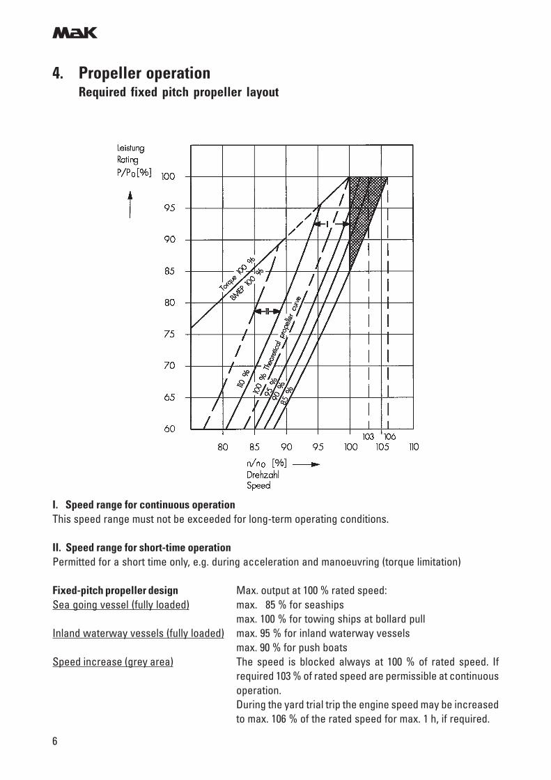
4. Propeller operationRequired fixed pitch propeller layout
I. Speed range for continuous operationThis speed range must not be exceeded for long-term operating conditions.
II. Speed range for short-time operationPermitted for a short time only, e.g. during acceleration and manoeuvring (torque limitation)
Fixed-pitch propeller design Max. output at 100 % rated speed:Sea going vessel (fully loaded) max. 85 % for seaships
max. 100 % for towing ships at bollard pullInland waterway vessels (fully loaded) max. 95 % for inland waterway vessels
max. 90 % for push boatsSpeed increase (grey area) The speed is blocked always at 100 % of rated speed. If
required 103 % of rated speed are permissible at continuousoperation.During the yard trial trip the engine speed may be increasedto max. 106 % of the rated speed for max. 1 h, if required.
m
7
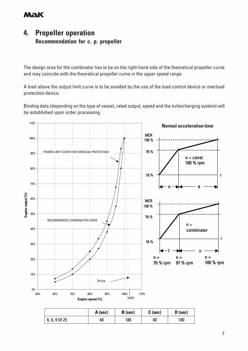
4. Propeller operationRecommendation for c. p. propeller
The design area for the combinator has to be on the right-hand side of the theoretical propeller curveand may coincide with the theoretical propeller curve in the upper speed range.
A load above the output limit curve is to be avoided by the use of the load control device or overloadprotection device.
Binding data (depending on the type of vessel, rated output, speed and the turbocharging system) willbe established upon order processing.
0%
10%
20%
30%
40%
50%
60%
70%
80%
90%
100%
110%
50% 60% 70% 80% 90% 100% 110%
Engine speed [%]
Engi
ne o
utpu
t [%
]
POWER LIMIT CURVE FOR OVERLOAD PROTECTION
RECOMMENDED COMBINATOR CURVE
103%
Droop
A (sec) B (sec) C (sec) D (sec)
6, 8, 9 M 25 40 180 40 180
Normal acceleration time
n = const100 % rpm
A
10 %
70 %
100 %
B
MCR
t
n = const100 % rpm
A
10 %
70 %
100 %
B
MCR
t
n =combinator
10 %
70 %
100 %MCR
n = 70 % rpm
n =97 % rpm
C D
n = 100 % rpm
t
n =combinator
10 %
70 %
100 %MCR
n = 70 % rpm
n =97 % rpm
C D
n = 100 % rpm
t
m
8
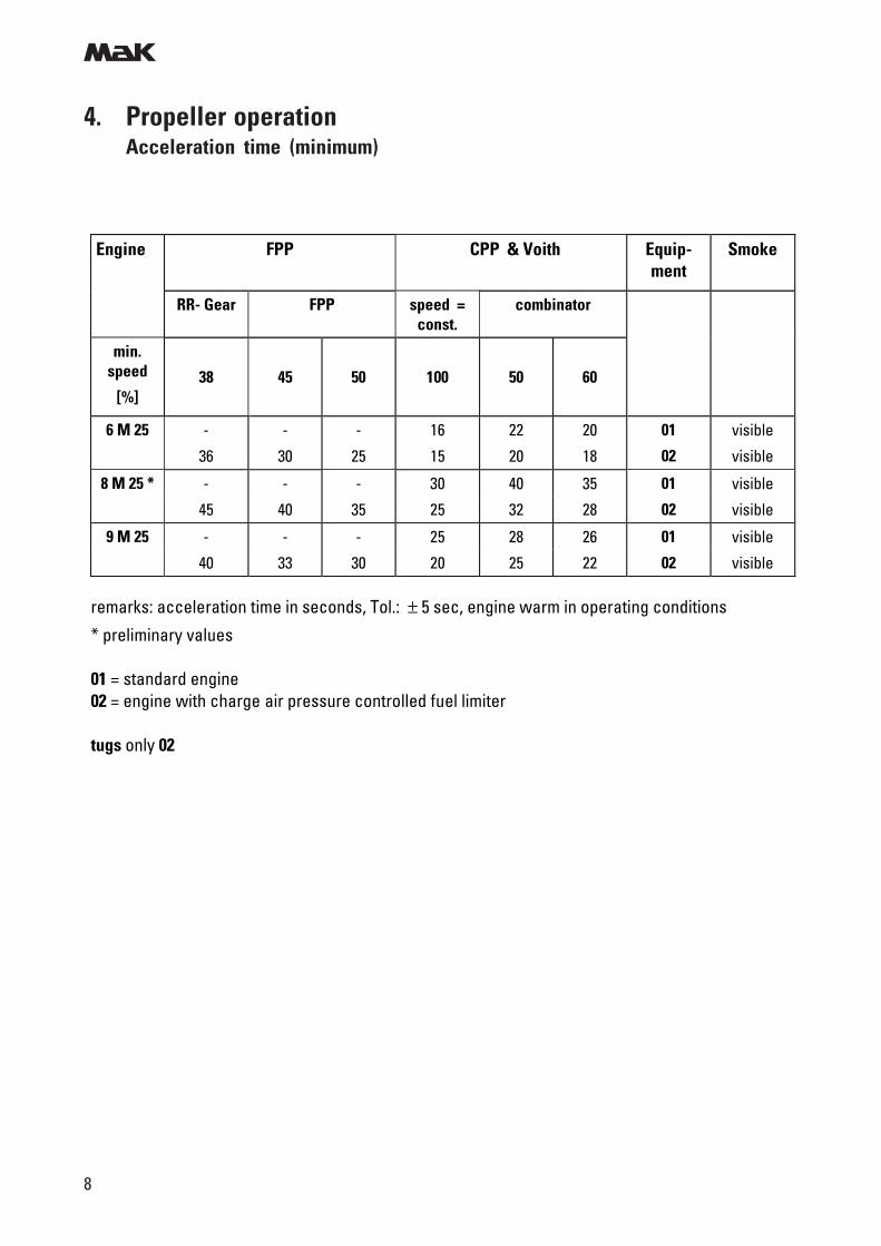
4. Propeller operationAcceleration time (minimum)
Engine FPP CPP & Voith
Equip-ment
Smoke
RR- Gear FPP speed = const.
combinator
min. speed
[%]
38
45
50
100
50
60
6 M 25
-
36
-
30
-
25
16
15
22
20
20
18
01
02
visible
visible
8 M 25 * - - - 30 40 35 01 visible
45 40 35 25 32 28 02 visible
9 M 25 - - - 25 28 26 01 visible
40 33 30 20 25 22 02 visible
remarks: acceleration time in seconds, Tol.: ± 5 sec, engine warm in operating conditions
* preliminary values
01 = standard engine 02 = engine with charge air pressure controlled fuel limiter tugs only 02
m
9
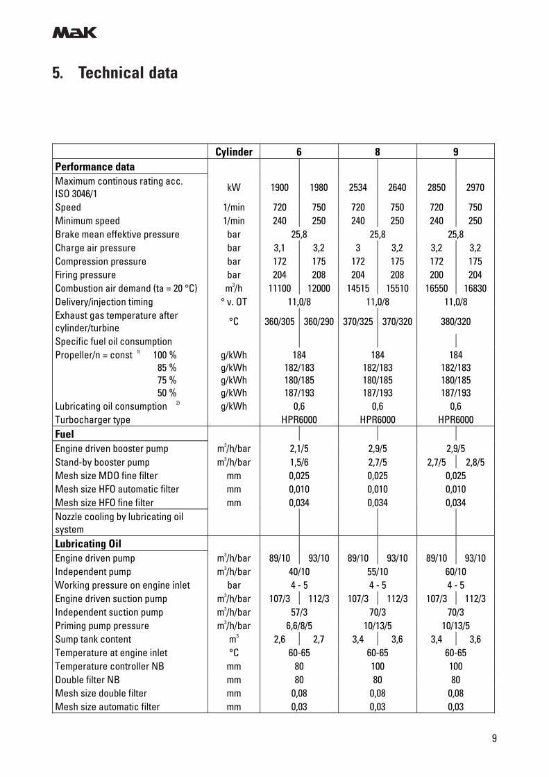
5. Technical data
Cylinder 6 8 9 Performance data Maximum continous rating acc. ISO 3046/1
kW 1900 1980 2534 2640 2850 2970
Speed 1/min 720 750 720 750 720 750 Minimum speed 1/min 240 250 240 250 240 250 Brake mean effektive pressure bar 25,8 25,8 25,8 Charge air pressure bar 3,1 3,2 3 3,2 3,2 3,2 Compression pressure bar 172 175 172 175 172 175 Firing pressure bar 204 208 204 208 200 204 Combustion air demand (ta = 20 °C) m3/h 11100 12000 14515 15510 16550 16830 Delivery/injection timing ° v. OT 11,0/8 11,0/8 11,0/8 Exhaust gas temperature after cylinder/turbine
°C 360/305 360/290 370/325 370/320 380/320
Specific fuel oil consumption Propeller/n = const 1) 100 % 85 % 75 % 50 %
g/kWh g/kWh g/kWh g/kWh
184 182/183 180/185 187/193
184 182/183 180/185 187/193
184 182/183 180/185 187/193
Lubricating oil consumption 2) g/kWh 0,6 0,6 0,6 Turbocharger type HPR6000 HPR6000 HPR6000 Fuel Engine driven booster pump m3/h/bar 2,1/5 2,9/5 2,9/5 Stand-by booster pump m3/h/bar 1,5/6 2,7/5 2,7/5 2,8/5 Mesh size MDO fine filter mm 0,025 0,025 0,025 Mesh size HFO automatic filter mm 0,010 0,010 0,010 Mesh size HFO fine filter mm 0,034 0,034 0,034 Nozzle cooling by lubricating oil system
Lubricating Oil Engine driven pump m3/h/bar 89/10 93/10 89/10 93/10 89/10 93/10 Independent pump m3/h/bar 40/10 55/10 60/10 Working pressure on engine inlet bar 4 - 5 4 - 5 4 - 5 Engine driven suction pump m3/h/bar 107/3 112/3 107/3 112/3 107/3 112/3 Independent suction pump m3/h/bar 57/3 70/3 70/3 Priming pump pressure m3/h/bar 6,6/8/5 10/13/5 10/13/5 Sump tank content m3 2,6 2,7 3,4 3,6 3,4 3,6 Temperature at engine inlet °C 60-65 60-65 60-65 Temperature controller NB mm 80 100 100 Double filter NB mm 80 80 80 Mesh size double filter mm 0,08 0,08 0,08 Mesh size automatic filter mm 0,03 0,03 0,03
m
10
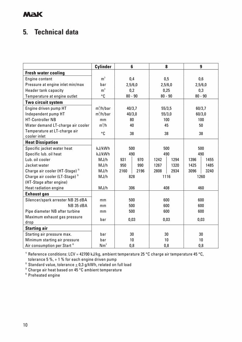
5. Technical data
Cylinder 6 8 9 Fresh water cooling Engine content m3 0,4 0,5 0,6 Pressure at engine inlet min/max bar Header tank capacity m3 Temperature at engine outlet °C
2,5/6,0 0,2
80 - 90
2,5/6,0 0,25
80 - 90
2,5/6,0 0,3
80 - 90 Two circuit system Engine driven pump HT m3/h/bar 40/3,7 55/3,5 60/3,7 Independent pump HT m3/h/bar 40/3,0 55/3,0 60/3,0 HT-Controller NB mm 80 100 100 Water demand LT-charge air cooler m3/h 40 45 50 Temperature at LT-charge air cooler inlet
°C 38 38 38
Heat Dissipation Specific jacket water heat kJ/kWh 500 500 500 Specific lub. oil heat kJ/kWh 490 490 490 Lub. oil cooler MJ/h 931 970 1242 1294 1396 1455 Jacket water MJ/h 950 990 1267 1320 1425 1485 Charge air cooler (HT-Stage) 3) MJ/h 2160 2196 2808 2934 3096 3240 Charge air cooler (LT-Stage) 3) MJ/h 828 1116 1260 (HT-Stage after engine) Heat radiation engine MJ/h 306 408 460 Exhaust gas Silencer/spark arrester NB 25 dBA mm 500 600 600 NB 35 dBA mm 500 600 600 Pipe diameter NB after turbine mm 500 600 600 Maximum exhaust gas pressure drop
bar 0,03 0,03 0,03
Starting air Starting air pressure max. bar 30 30 30 Minimum starting air pressure bar 10 10 10 Air consumption per Start 4) Nm3 0,8 0,8 0,8 1) Reference conditions: LCV = 42700 kJ/kg, ambient temperature 25 °C charge air temperature 45 °C,
tolerance 5 %, + 1 % for each engine driven pump 2) Standard value, tolerance + 0,3 g/kWh, related on full load 3) Charge air heat based on 45 °C ambient temperature 4) Preheated engine
m
11
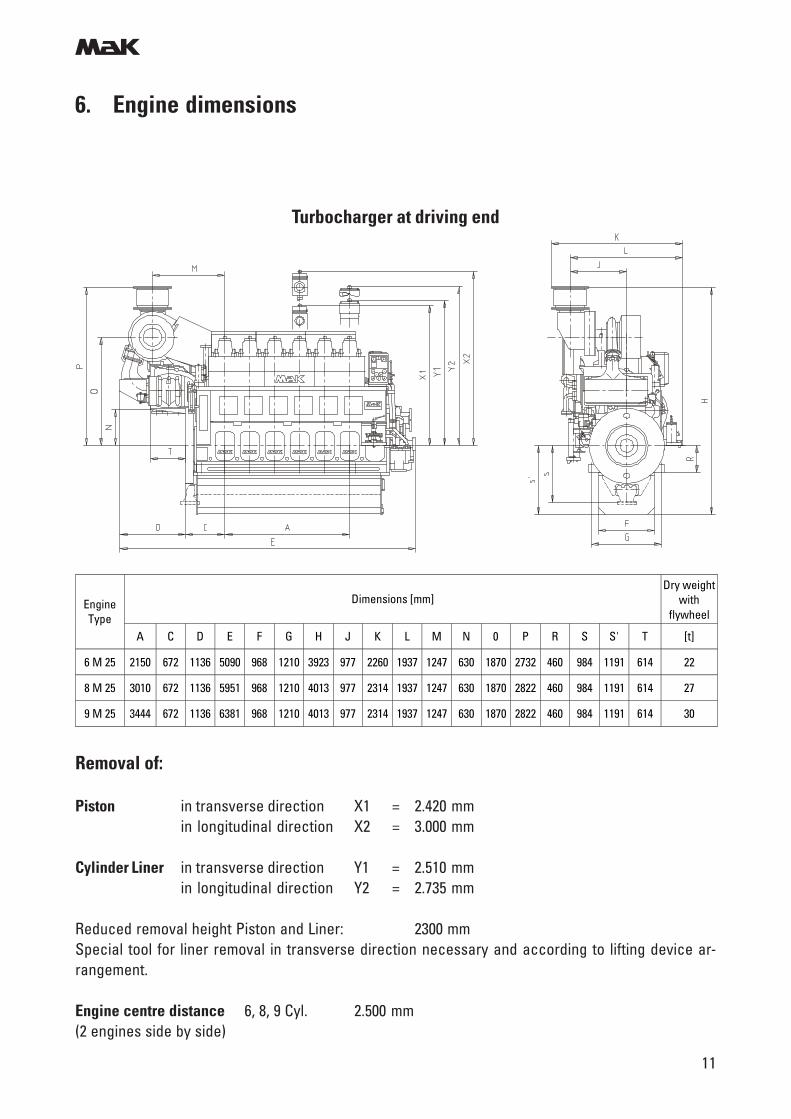
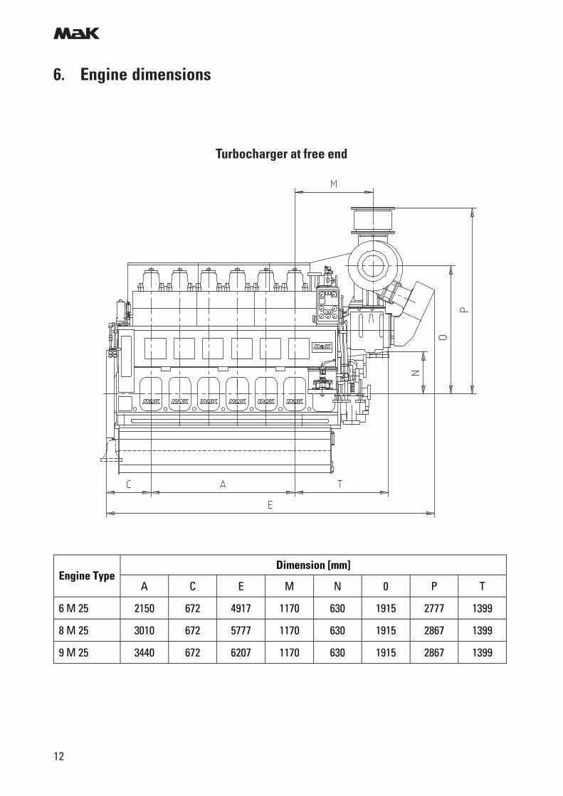
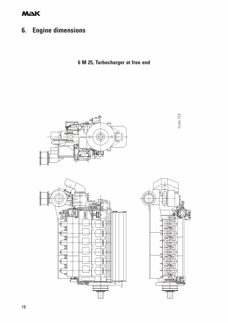
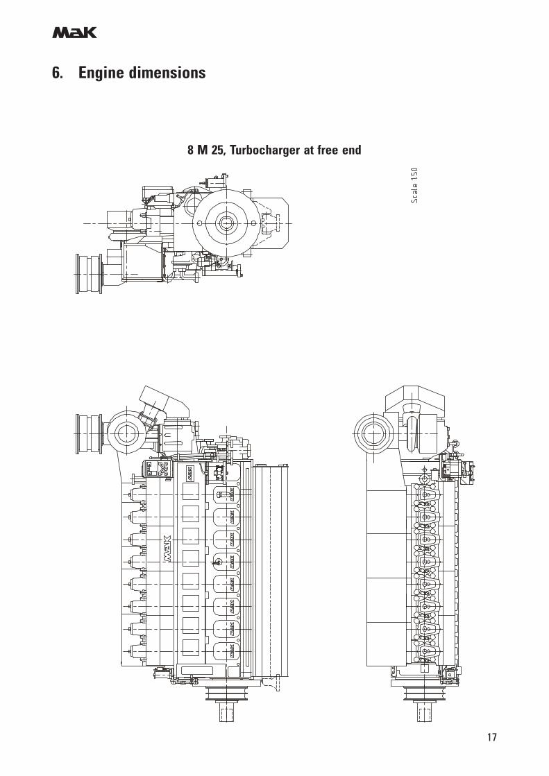
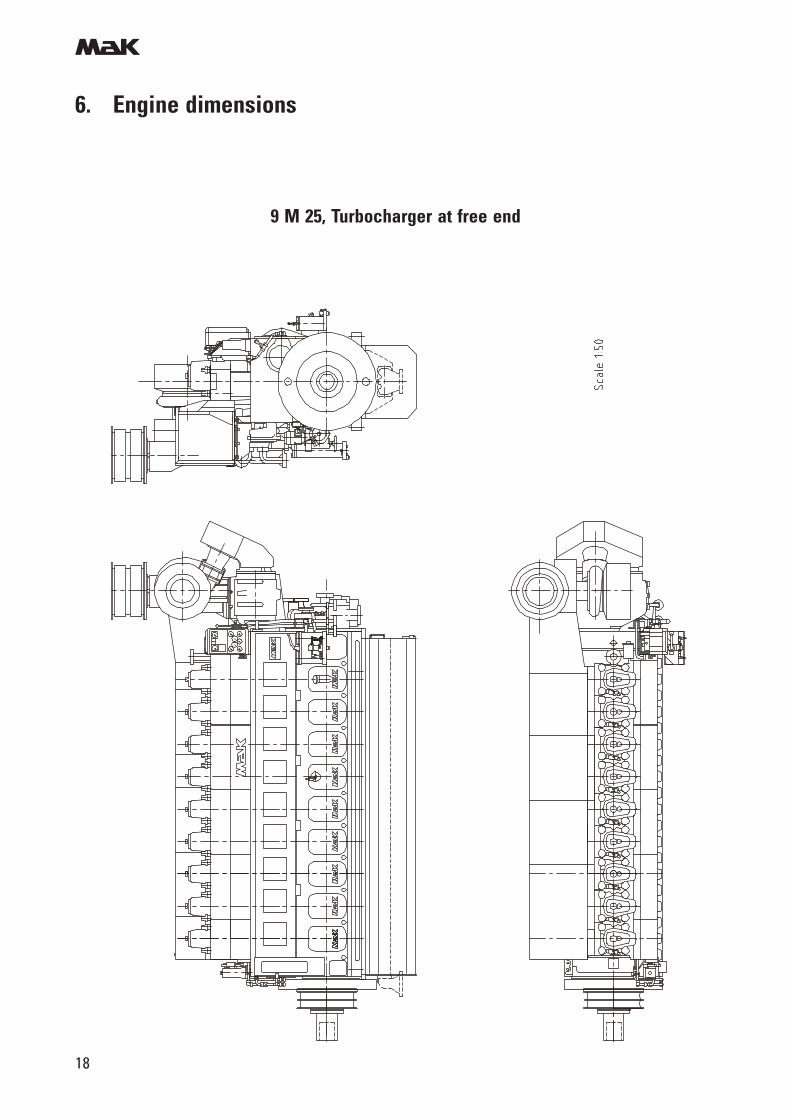
6. Engine dimensions
Removal of:
Piston in transverse direction X1 = 2.420 mmin longitudinal direction X2 = 3.000 mm
Cylinder Liner in transverse direction Y1 = 2.510 mmin longitudinal direction Y2 = 2.735 mm
Reduced removal height Piston and Liner: 2300 mmSpecial tool for liner removal in transverse direction necessary and according to lifting device ar-rangement.
Engine centre distance 6, 8, 9 Cyl. 2.500 mm(2 engines side by side)
Turbocharger at driving end
Dimensions [mm] Dry weight
with flywheel
Engine Type
A C D E F G H J K L M N 0 P R S S' T [t]
6 M 25 2150 672 1136 5090 968 1210 3923 977 2260 1937 1247 630 1870 2732 460 984 1191 614 22
8 M 25 3010 672 1136 5951 968 1210 4013 977 2314 1937 1247 630 1870 2822 460 984 1191 614 27
9 M 25 3444 672 1136 6381 968 1210 4013 977 2314 1937 1247 630 1870 2822 460 984 1191 614 30
m
12
6. Engine dimensions
Turbocharger at free end
Dimension [mm] Engine Type
A C E M N 0 P T
6 M 25 2150 672 4917 1170 630 1915 2777 1399
8 M 25 3010 672 5777 1170 630 1915 2867 1399
9 M 25 3440 672 6207 1170 630 1915 2867 1399
m
13
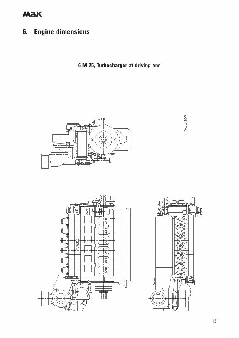
6. Engine dimensions
6 M 25, Turbocharger at driving end
m
14
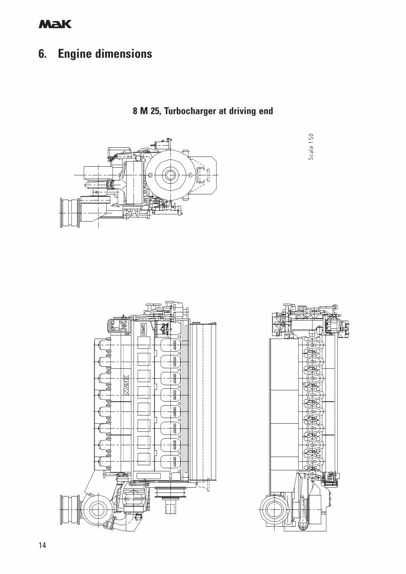
6. Engine dimensions
8 M 25, Turbocharger at driving end
m
15
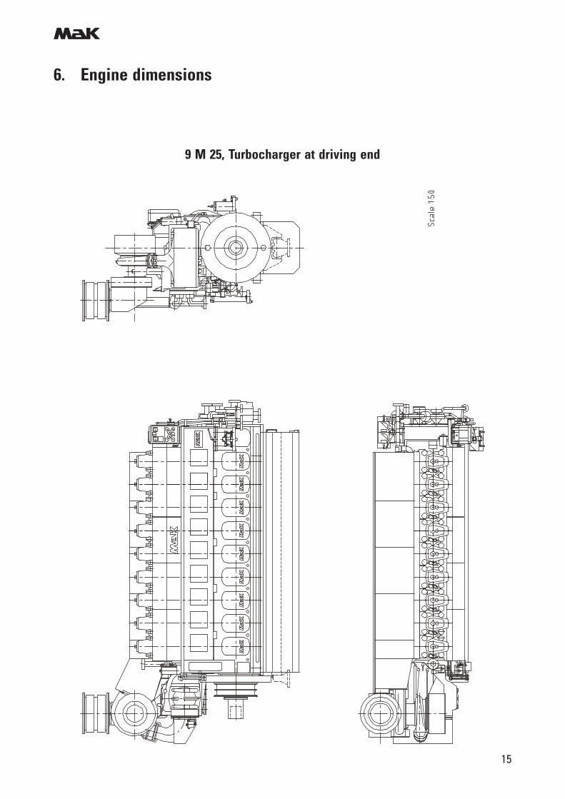
6. Engine dimensions
9 M 25, Turbocharger at driving end
m
16
6. Engine dimensions
6 M 25, Turbocharger at free end
m
17
6. Engine dimensions
8 M 25, Turbocharger at free end
m
18
6. Engine dimensions
9 M 25, Turbocharger at free end
m
19
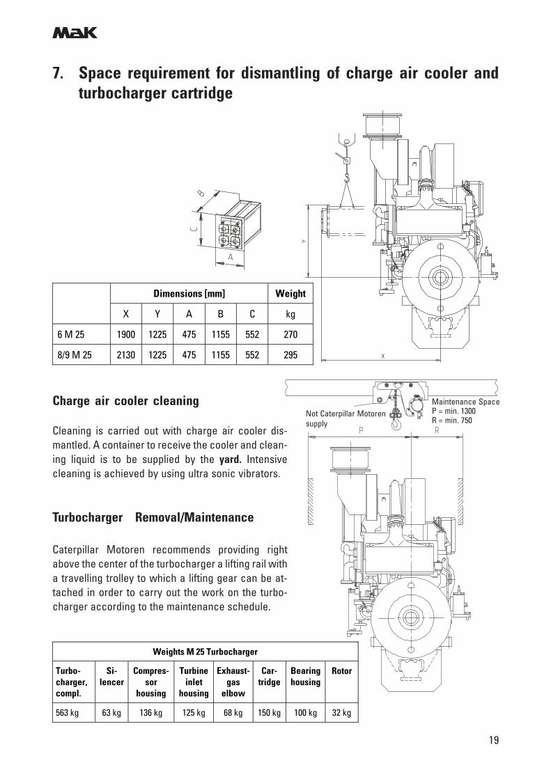
7. Space requirement for dismantling of charge air cooler andturbocharger cartridge
Charge air cooler cleaning
Cleaning is carried out with charge air cooler dis-mantled. A container to receive the cooler and clean-ing liquid is to be supplied by the yard. Intensivecleaning is achieved by using ultra sonic vibrators.
Turbocharger Removal/Maintenance
Caterpillar Motoren recommends providing rightabove the center of the turbocharger a lifting rail witha travelling trolley to which a lifting gear can be at-tached in order to carry out the work on the turbo-charger according to the maintenance schedule.
Weights M 25 Turbocharger
Turbo-charger, compl.
Si-lencer
Compres-sor
housing
Turbine inlet
housing
Exhaust-gas
elbow
Car-tridge
Bearing housing
Rotor
563 kg 63 kg 136 kg 125 kg 68 kg 150 kg 100 kg 32 kg
Dimensions [mm] Weight
X Y A B C kg
6 M 25 1900 1225 475 1155 552 270
8/9 M 25 2130 1225 475 1155 552 295
Not Caterpillar Motorensupply
Maintenance SpaceP = min. 1300R = min. 750
m
20
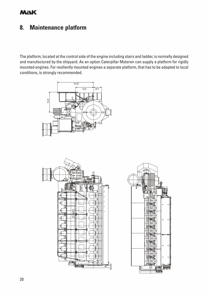
8. Maintenance platform
The platform, located at the control side of the engine including stairs and ladder, is normally designedand manufactured by the shipyard. As an option Caterpillar Motoren can supply a platform for rigidlymounted engines. For resiliently mounted engines a separate platform, that has to be adapted to localconditions, is strongly recommended.
m
21
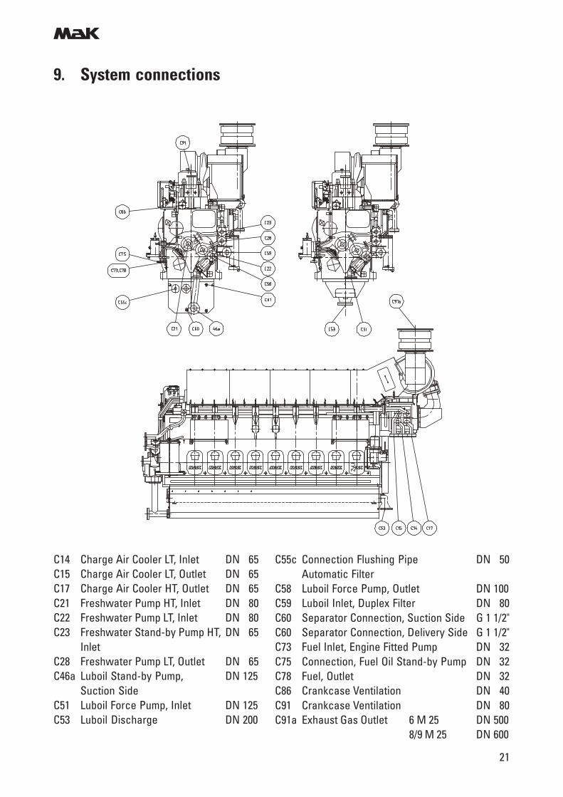
9. System connections
C14 Charge Air Cooler LT, Inlet DN 65C15 Charge Air Cooler LT, Outlet DN 65C17 Charge Air Cooler HT, Outlet DN 65C21 Freshwater Pump HT, Inlet DN 80C22 Freshwater Pump LT, Inlet DN 80C23 Freshwater Stand-by Pump HT, DN 65
InletC28 Freshwater Pump LT, Outlet DN 65C46a Luboil Stand-by Pump, DN 125
Suction SideC51 Luboil Force Pump, Inlet DN 125C53 Luboil Discharge DN 200
C55c Connection Flushing Pipe DN 50Automatic Filter
C58 Luboil Force Pump, Outlet DN 100C59 Luboil Inlet, Duplex Filter DN 80C60 Separator Connection, Suction Side G 1 1/2"C60 Separator Connection, Delivery Side G 1 1/2"C73 Fuel Inlet, Engine Fitted Pump DN 32C75 Connection, Fuel Oil Stand-by Pump DN 32C78 Fuel, Outlet DN 32C86 Crankcase Ventilation DN 40C91 Crankcase Ventilation DN 80C91a Exhaust Gas Outlet 6 M 25 DN 500
8/9 M 25 DN 600
m
22
10. Fuel oil system
Gas oil/MDO operation
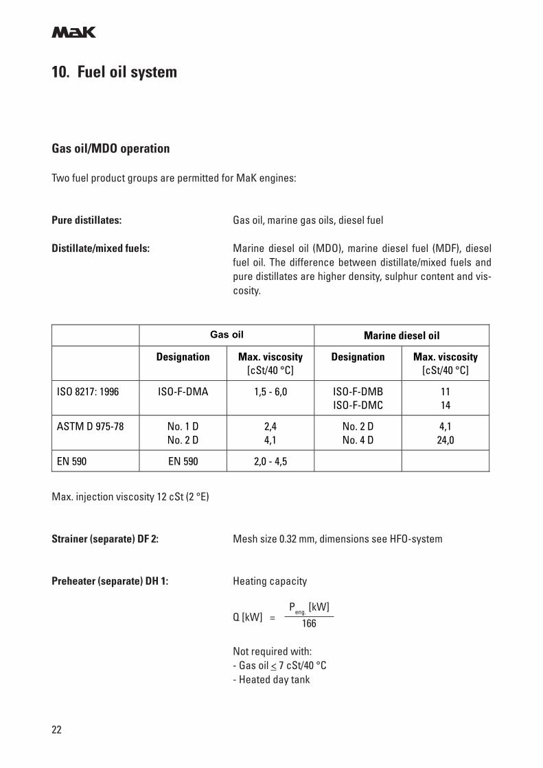
Two fuel product groups are permitted for MaK engines:
Pure distillates: Gas oil, marine gas oils, diesel fuel
Distillate/mixed fuels: Marine diesel oil (MDO), marine diesel fuel (MDF), dieselfuel oil. The difference between distillate/mixed fuels andpure distillates are higher density, sulphur content and vis-cosity.
Gas oil Marine diesel oil
Designation Max. viscosity [cSt/40 °C]
Designation Max. viscosity [cSt/40 °C]
ISO 8217: 1996 ISO-F-DMA 1,5 - 6,0 ISO-F-DMB ISO-F-DMC
11 14
ASTM D 975-78 No. 1 D No. 2 D
2,4 4,1
No. 2 D No. 4 D
4,1 24,0
EN 590 EN 590 2,0 - 4,5
Max. injection viscosity 12 cSt (2 °E)
Strainer (separate) DF 2: Mesh size 0.32 mm, dimensions see HFO-system
Preheater (separate) DH 1: Heating capacity
Not required with:- Gas oil < 7 cSt/40 °C- Heated day tank
Q [kW] =Peng. [kW]
166
m
23
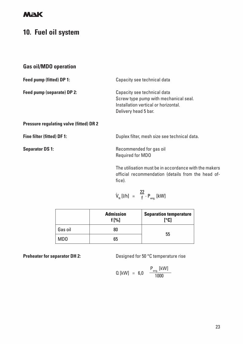
Gas oil/MDO operation
Feed pump (fitted) DP 1: Capacity see technical data
Feed pump (separate) DP 2: Capacity see technical dataScrew type pump with mechanical seal.Installation vertical or horizontal.Delivery head 5 bar.
Pressure regulating valve (fitted) DR 2
Fine filter (fitted) DF 1: Duplex filter, mesh size see technical data.
Separator DS 1: Recommended for gas oilRequired for MDO
The utilisation must be in accordance with the makersofficial recommendation (details from the head of-fice).
10. Fuel oil system
VN [l/h] = · Peng. [kW]. 22
f
Preheater for separator DH 2: Designed for 50 °C temperature rise
Q [kW] = 6,0Peng. [kW]
1000
Admission f [%]
Separation temperature [°C]
Gas oil 80
MDO 65 55
m
24
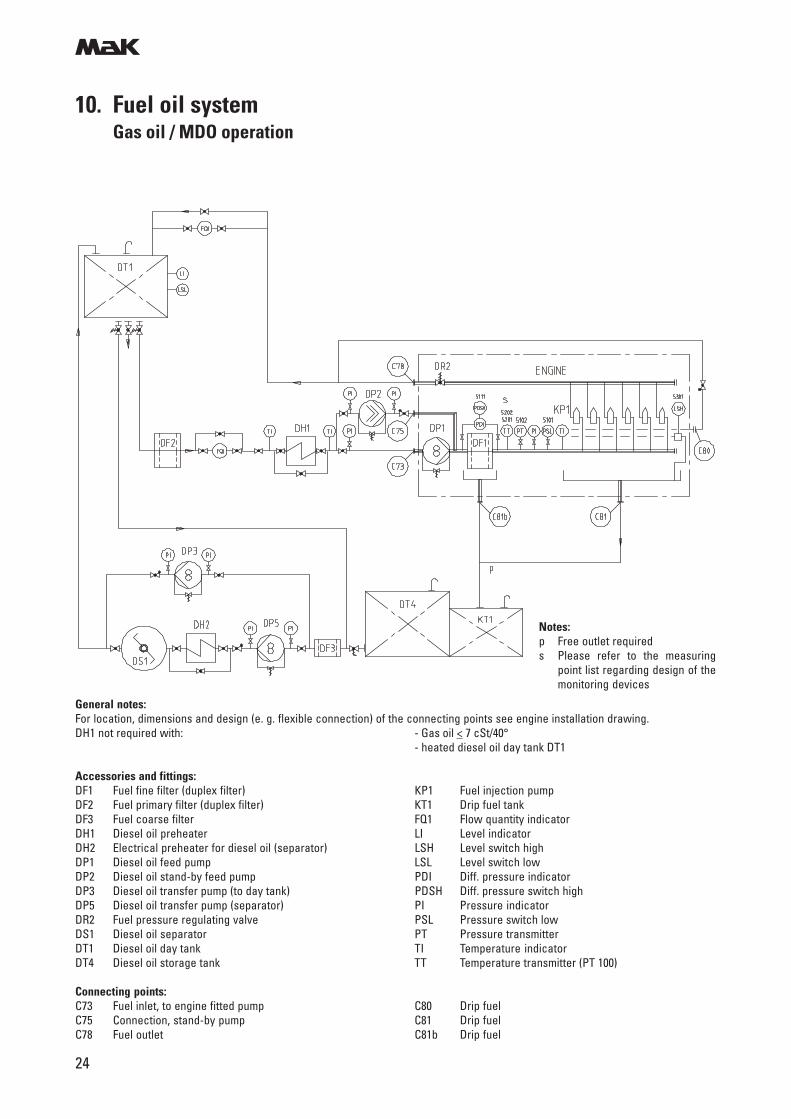
10. Fuel oil systemGas oil / MDO operation
General notes:For location, dimensions and design (e. g. flexible connection) of the connecting points see engine installation drawing.DH1 not required with: - Gas oil < 7 cSt/40°
- heated diesel oil day tank DT1
Accessories and fittings:DF1 Fuel fine filter (duplex filter) KP1 Fuel injection pumpDF2 Fuel primary filter (duplex filter) KT1 Drip fuel tankDF3 Fuel coarse filter FQ1 Flow quantity indicatorDH1 Diesel oil preheater LI Level indicatorDH2 Electrical preheater for diesel oil (separator) LSH Level switch highDP1 Diesel oil feed pump LSL Level switch lowDP2 Diesel oil stand-by feed pump PDI Diff. pressure indicatorDP3 Diesel oil transfer pump (to day tank) PDSH Diff. pressure switch highDP5 Diesel oil transfer pump (separator) PI Pressure indicatorDR2 Fuel pressure regulating valve PSL Pressure switch lowDS1 Diesel oil separator PT Pressure transmitterDT1 Diesel oil day tank TI Temperature indicatorDT4 Diesel oil storage tank TT Temperature transmitter (PT 100)
Connecting points:C73 Fuel inlet, to engine fitted pump C80 Drip fuelC75 Connection, stand-by pump C81 Drip fuelC78 Fuel outlet C81b Drip fuel
Notes:p Free outlet requireds Please refer to the measuring
point list regarding design of themonitoring devices
m
25
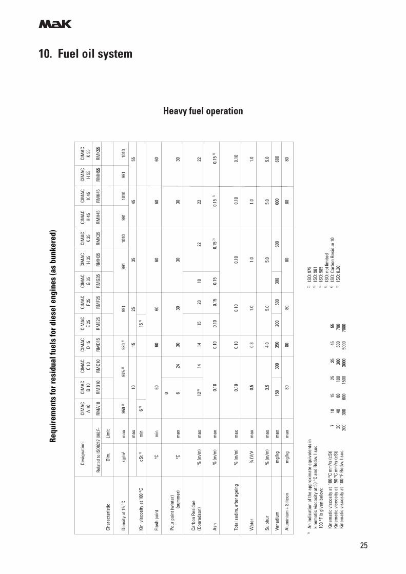
10. Fuel oil system
Des
igna
tion:
CIM
ACCI
MAC
CIM
ACCI
MAC
CIM
ACCI
MAC
CIM
ACCI
MAC
CIM
ACCI
MAC
CIM
ACCI
MAC
CIM
ACA
10B
10C
10D
15E
25F
25G
35H
35K
35H
45K
45H
55K
55
Rela
ted
to IS
O821
7 (9
6):F
-RM
A10
RMB1
0RM
C10
RMD1
5RM
E25
RMF2
5RM
G35
RMH3
5RM
K35
RMH4
5RM
K45
RMH5
5RM
K55
Char
acte
ristic
Dim
.Li
mit
Dens
ity a
t 15
°Ckg
/m3
max
950
2)97
5 3)
98
0 4)
991
99
1
10
1099
110
1099
110
10
max
1015
25
3545
55
Kin.
vis
cosi
ty a
t 100
°CcS
t 1)m
in6
5)15
5)
Flas
h po
int
°Cm
in60
6060
6060
60
0
Po
ur p
oint
(win
ter)
(s
umm
er)
°Cm
ax6
2430
30
30
30
30
Carb
on R
esid
ue(C
onra
dson
)%
(m/m
)m
ax12
6)
14
1415
2018
22
22
22
Ash
% (m
/m)
max
0.10
0.10
0.10
0.15
0.15
0.15
7)
0.
15 7)
0.
15 7)
Tota
l sed
im, a
fter a
gein
g%
(m/m
)m
ax0.
100.
100.
10
0.
100.
10
0.
10
Wat
er%
(V/V
max
0.5
0.8
1.0
1.0
1.0
1.0
Sulp
hur
% (m
/m)
max
3.5
4.0
5.0
5.0
5.0
5.0
Vana
dium
mg/
kgm
ax15
0
30
035
020
050
030
060
0
60
0
60
0
Alum
iniu
m +
Sili
con
mg/
kgm
ax80
8080
8080
80
1)An
indi
catio
n of
the
appr
oxim
ate
equi
vale
nts
inki
nem
atic
vis
cosi
ty a
t 50
°C a
nd R
edw
. I s
ec.
100
°F is
giv
en b
elow
:
Kine
mat
ic v
isco
sity
at
100
°C m
m2 /s
(cSt
)Ki
nem
atic
vis
cosi
ty a
t 5
0 °C
mm
2 /s (c
St)
Kine
mat
ic v
isco
sity
at
100
°F R
edw
. I s
ec.
2)IS
O: 9
753)
ISO:
981
4)IS
O: 9
855)
ISO:
not
lim
ited
6)IS
O: C
arbo
n Re
sidu
e 10
7)IS
O: 0
.20
7
10
15
2
5
35
4
5
55
30
40
80
180
380
500
700
200
300
600
1500
3000
5000
7000
Requ
irem
ents
for r
esid
ual f
uels
for d
iese
l eng
ines
(as
bunk
ered
)
Heavy fuel operation
m
26
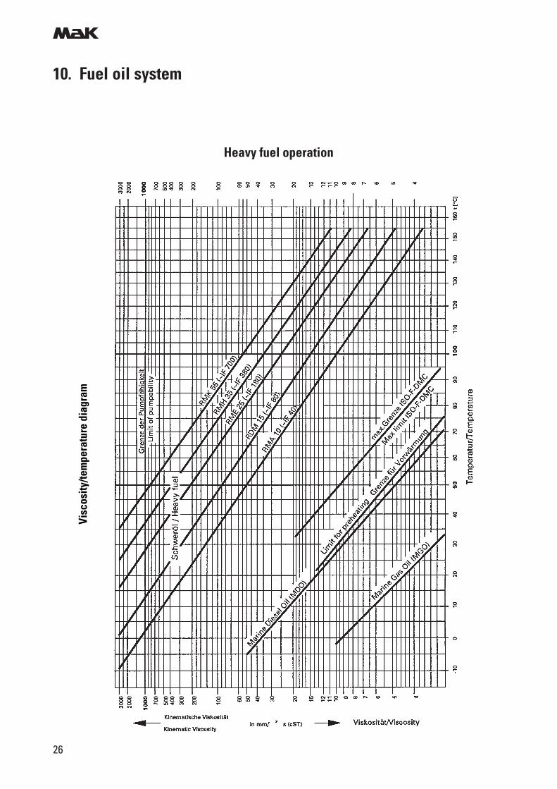
10. Fuel oil system
Heavy fuel operation
Visc
osity
/tem
pera
ture
dia
gram
m
27
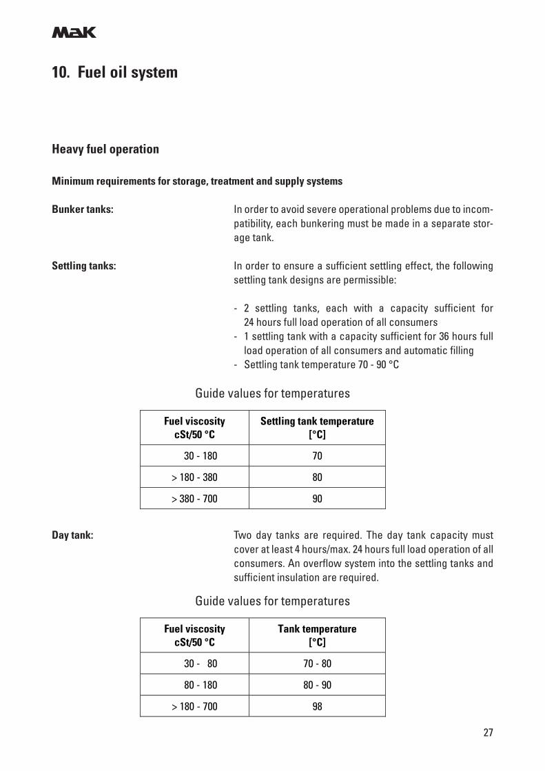
10. Fuel oil system
Heavy fuel operation
Minimum requirements for storage, treatment and supply systems
Bunker tanks: In order to avoid severe operational problems due to incom-patibility, each bunkering must be made in a separate stor-age tank.
Settling tanks: In order to ensure a sufficient settling effect, the followingsettling tank designs are permissible:
- 2 settling tanks, each with a capacity sufficient for24 hours full load operation of all consumers
- 1 settling tank with a capacity sufficient for 36 hours fullload operation of all consumers and automatic filling
- Settling tank temperature 70 - 90 °C
Guide values for temperatures
Day tank: Two day tanks are required. The day tank capacity mustcover at least 4 hours/max. 24 hours full load operation of allconsumers. An overflow system into the settling tanks andsufficient insulation are required.
Fuel viscosity cSt/50 °C
Settling tank temperature [°C]
30 - 180 70
> 180 - 380 80
> 380 - 700 90
Guide values for temperatures
Fuel viscosity cSt/50 °C
Tank temperature [°C]
30 - 80 70 - 80
80 - 180 80 - 90
> 180 - 700 98
m
28
10. Fuel oil systemHeavy fuel operation
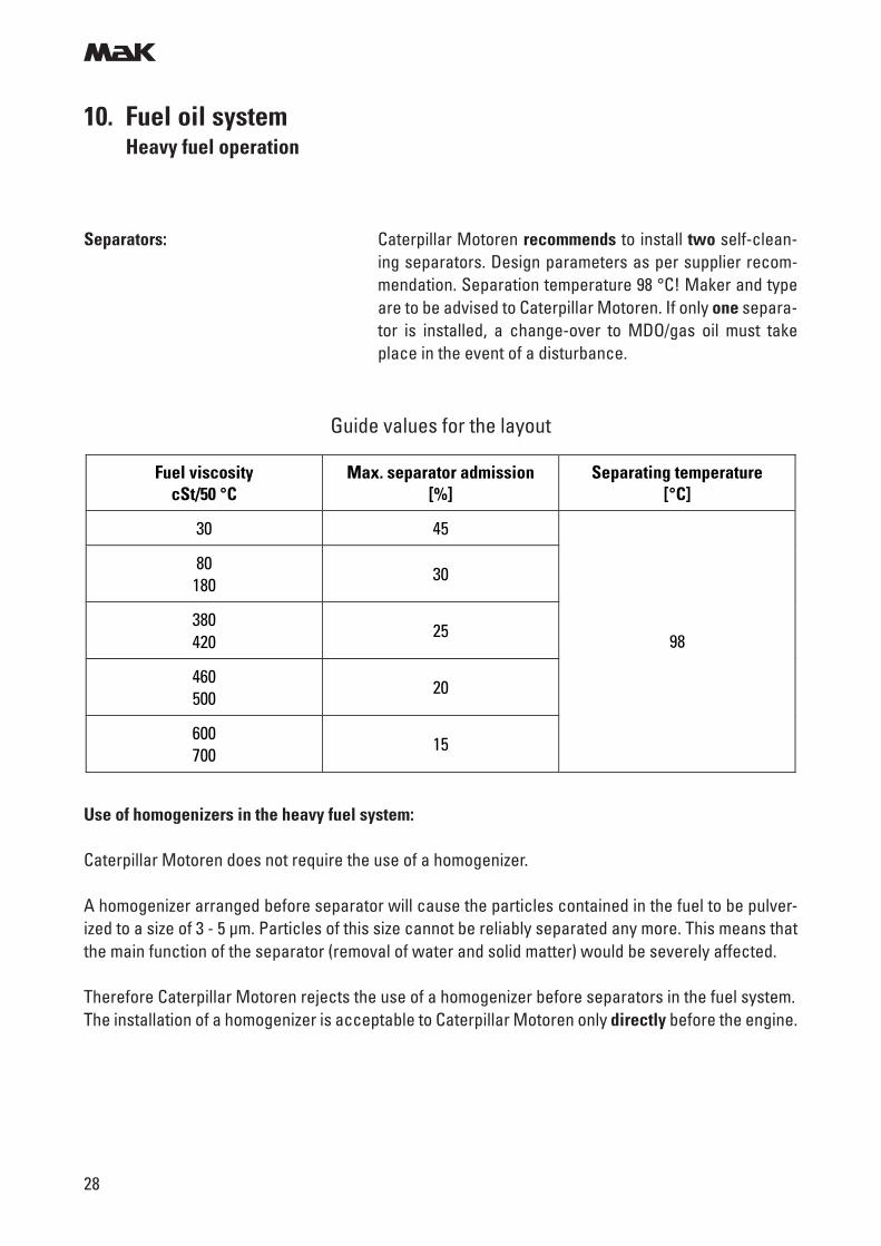
Separators: Caterpillar Motoren recommends to install two self-clean-ing separators. Design parameters as per supplier recom-mendation. Separation temperature 98 °C! Maker and typeare to be advised to Caterpillar Motoren. If only one separa-tor is installed, a change-over to MDO/gas oil must takeplace in the event of a disturbance.
Guide values for the layout
Use of homogenizers in the heavy fuel system:
Caterpillar Motoren does not require the use of a homogenizer.
A homogenizer arranged before separator will cause the particles contained in the fuel to be pulver-ized to a size of 3 - 5 µm. Particles of this size cannot be reliably separated any more. This means thatthe main function of the separator (removal of water and solid matter) would be severely affected.
Therefore Caterpillar Motoren rejects the use of a homogenizer before separators in the fuel system.The installation of a homogenizer is acceptable to Caterpillar Motoren only directly before the engine.
Fuel viscosity cSt/50 °C
Max. separator admission [%]
Separating temperature [°C]
30 45
80 180
30
380 420
25
460 500
20
600 700
15
98
m
29
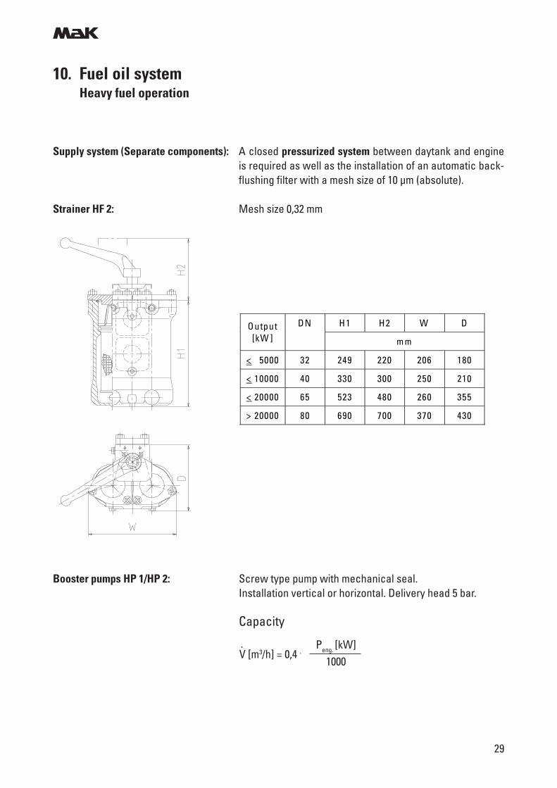
Booster pumps HP 1/HP 2: Screw type pump with mechanical seal.Installation vertical or horizontal. Delivery head 5 bar.
Capacity
V [m3/h] = 0,4 .. Peng. [kW]
1000
10. Fuel oil systemHeavy fuel operation
DN H1 H2 W D Output [kW ] m m
< 5000 32 249 220 206 180
< 10000 40 330 300 250 210
< 20000 65 523 480 260 355
> 20000 80 690 700 370 430
Supply system (Separate components): A closed pressurized system between daytank and engineis required as well as the installation of an automatic back-flushing filter with a mesh size of 10 µm (absolute).
Strainer HF 2: Mesh size 0,32 mm
m
30
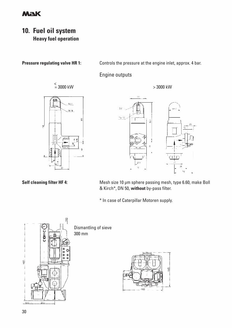
Self cleaning filter HF 4: Mesh size 10 µm sphere passing mesh, type 6.60, make Boll& Kirch*, DN 50, without by-pass filter.
* In case of Caterpillar Motoren supply.
10. Fuel oil systemHeavy fuel operation
Dismantling of sieve300 mm
Pressure regulating valve HR 1: Controls the pressure at the engine inlet, approx. 4 bar.
Engine outputs
= 3000 kW > 3000 kW<
m
31
Final preheater HH 1/HH 2: Heating media:
- Electric current (max. surface power density 1.1 W/cm2)- Steam- Thermal oil
Temperature at engine inlet max 150 °C.
Viscosimeter HR 2: Controls the injection viscosity to 10 - 12 cSt.
Fine filter (fitted) HF 1: - Mesh size 34 µm- Without heating- Differential pressure indication and alarm contact fitted
Fuel Cooler DH 3: Necessary for heat dissipation under diesel oil operationwith low viscosity (< 10 cSt/40 °C). The injection pumps aresupplying the fuel oil with heat, which is not carried off suffi-ciently by the recirculation.In MDO-systems the cooling can be carried out via the daytank.
V [m3/h] = 0,7 ...... Peng. [kW]
1000
Circulating pumps HP 3/HP 4: Design see pressure pumps.
Capacity
10. Fuel oil systemHeavy fuel operation
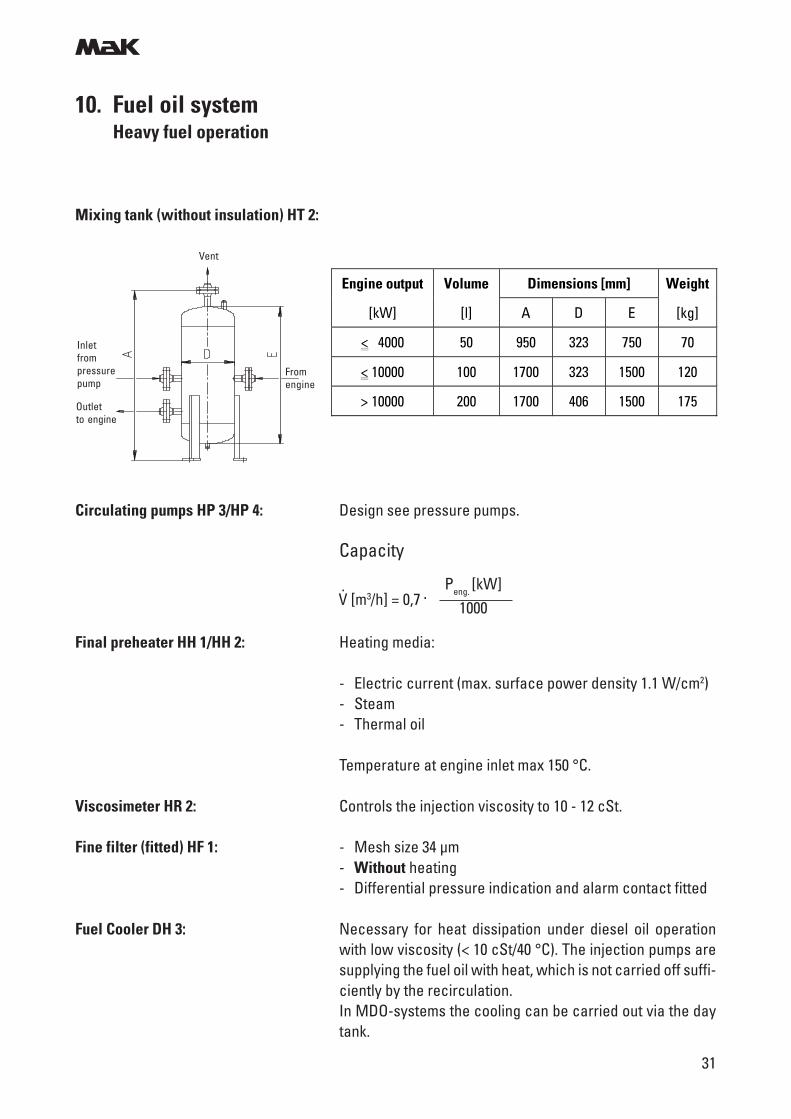
Mixing tank (without insulation) HT 2:
Engine output Volume Dimensions [mm] Weight
[kW] [l] A D E [kg]
< 4000 50 950 323 750 70
< 10000 100 1700 323 1500 120
> 10000 200 1700 406 1500 175
Vent
Inletfrompressurepump
Fromengine
Outletto engine
m
32
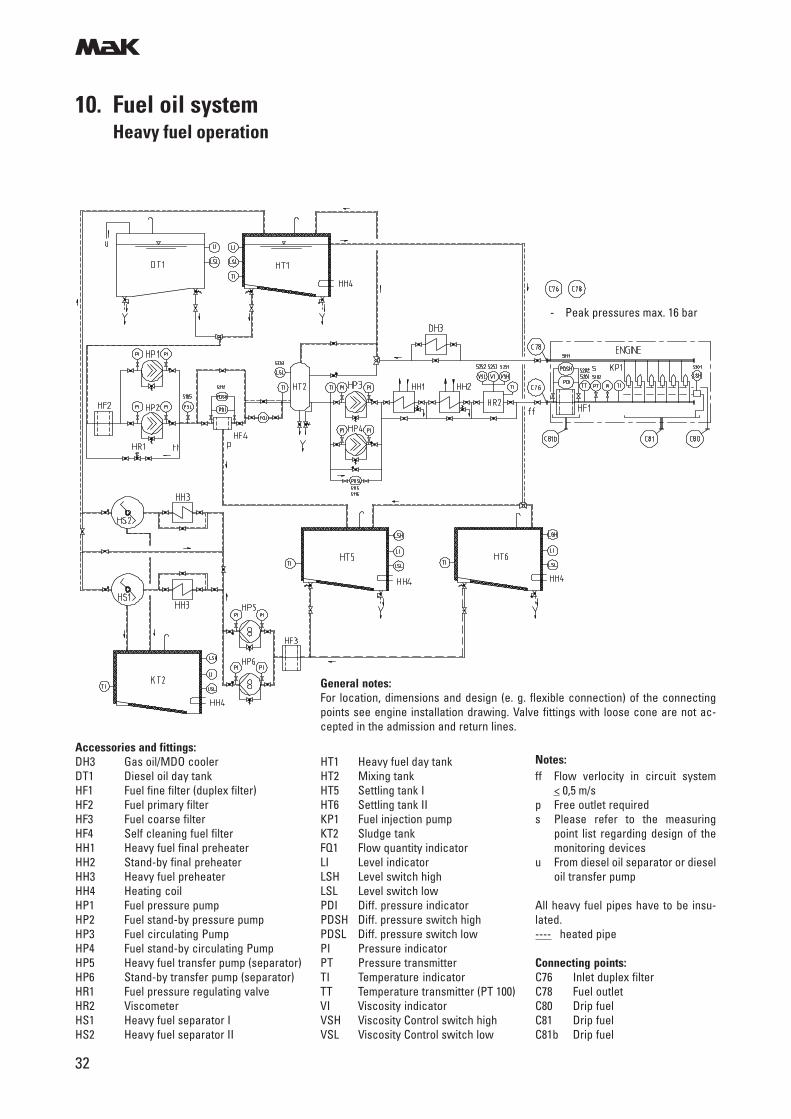
10. Fuel oil systemHeavy fuel operation
Notes:ff Flow verlocity in circuit system
< 0,5 m/sp Free outlet requireds Please refer to the measuring
point list regarding design of themonitoring devices
u From diesel oil separator or dieseloil transfer pump
All heavy fuel pipes have to be insu-lated.---- heated pipe
Connecting points:C76 Inlet duplex filterC78 Fuel outletC80 Drip fuelC81 Drip fuelC81b Drip fuel
Accessories and fittings:DH3 Gas oil/MDO cooler HT1 Heavy fuel day tankDT1 Diesel oil day tank HT2 Mixing tankHF1 Fuel fine filter (duplex filter) HT5 Settling tank IHF2 Fuel primary filter HT6 Settling tank IIHF3 Fuel coarse filter KP1 Fuel injection pumpHF4 Self cleaning fuel filter KT2 Sludge tankHH1 Heavy fuel final preheater FQ1 Flow quantity indicatorHH2 Stand-by final preheater LI Level indicatorHH3 Heavy fuel preheater LSH Level switch highHH4 Heating coil LSL Level switch lowHP1 Fuel pressure pump PDI Diff. pressure indicatorHP2 Fuel stand-by pressure pump PDSH Diff. pressure switch highHP3 Fuel circulating Pump PDSL Diff. pressure switch lowHP4 Fuel stand-by circulating Pump PI Pressure indicatorHP5 Heavy fuel transfer pump (separator) PT Pressure transmitterHP6 Stand-by transfer pump (separator) TI Temperature indicatorHR1 Fuel pressure regulating valve TT Temperature transmitter (PT 100)HR2 Viscometer VI Viscosity indicatorHS1 Heavy fuel separator I VSH Viscosity Control switch highHS2 Heavy fuel separator II VSL Viscosity Control switch low
General notes:For location, dimensions and design (e. g. flexible connection) of the connectingpoints see engine installation drawing. Valve fittings with loose cone are not ac-cepted in the admission and return lines.
- Peak pressures max. 16 bar
m
33
10. Fuel oil systemHeavy fuel operation
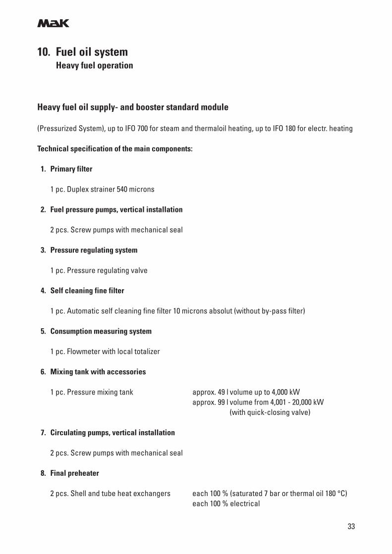
Heavy fuel oil supply- and booster standard module
(Pressurized System), up to IFO 700 for steam and thermaloil heating, up to IFO 180 for electr. heating
Technical specification of the main components:
1. Primary filter
1 pc. Duplex strainer 540 microns
2. Fuel pressure pumps, vertical installation
2 pcs. Screw pumps with mechanical seal
3. Pressure regulating system
1 pc. Pressure regulating valve
4. Self cleaning fine filter
1 pc. Automatic self cleaning fine filter 10 microns absolut (without by-pass filter)
5. Consumption measuring system
1 pc. Flowmeter with local totalizer
6. Mixing tank with accessories
1 pc. Pressure mixing tank approx. 49 l volume up to 4,000 kWapprox. 99 l volume from 4,001 - 20,000 kW
(with quick-closing valve)
7. Circulating pumps, vertical installation
2 pcs. Screw pumps with mechanical seal
8. Final preheater
2 pcs. Shell and tube heat exchangers each 100 % (saturated 7 bar or thermal oil 180 °C)each 100 % electrical
m
34
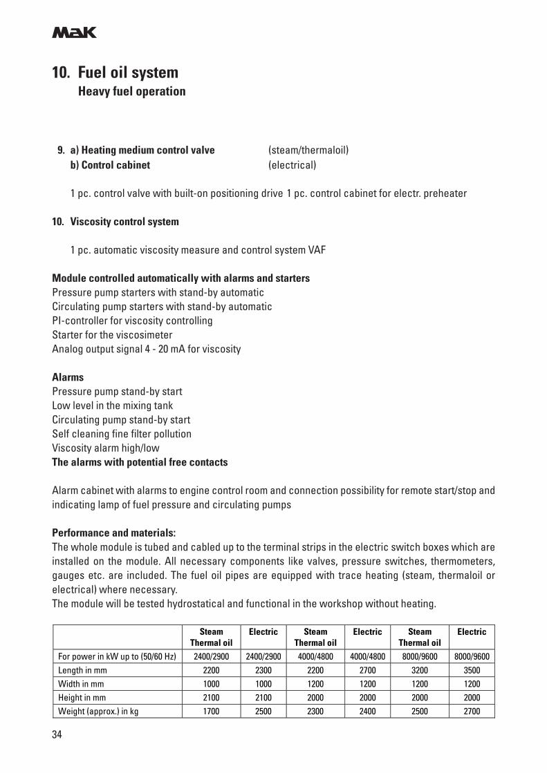
9. a) Heating medium control valve (steam/thermaloil)b) Control cabinet (electrical)
1 pc. control valve with built-on positioning drive 1 pc. control cabinet for electr. preheater
10. Viscosity control system
1 pc. automatic viscosity measure and control system VAF
Module controlled automatically with alarms and startersPressure pump starters with stand-by automaticCirculating pump starters with stand-by automaticPI-controller for viscosity controllingStarter for the viscosimeterAnalog output signal 4 - 20 mA for viscosity
AlarmsPressure pump stand-by startLow level in the mixing tankCirculating pump stand-by startSelf cleaning fine filter pollutionViscosity alarm high/lowThe alarms with potential free contacts
Alarm cabinet with alarms to engine control room and connection possibility for remote start/stop andindicating lamp of fuel pressure and circulating pumps
Performance and materials:The whole module is tubed and cabled up to the terminal strips in the electric switch boxes which areinstalled on the module. All necessary components like valves, pressure switches, thermometers,gauges etc. are included. The fuel oil pipes are equipped with trace heating (steam, thermaloil orelectrical) where necessary.The module will be tested hydrostatical and functional in the workshop without heating.
10. Fuel oil systemHeavy fuel operation
Steam Thermal oil
Electric Steam Thermal oil
Electric Steam Thermal oil
Electric
For power in kW up to (50/60 Hz) 2400/2900 2400/2900 4000/4800 4000/4800 8000/9600 8000/9600 Length in mm 2200 2300 2200 2700 3200 3500 Width in mm 1000 1000 1200 1200 1200 1200 Height in mm 2100 2100 2000 2000 2000 2000 Weight (approx.) in kg 1700 2500 2300 2400 2500 2700
m
35
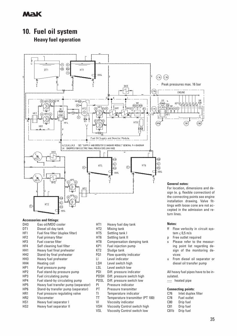
10. Fuel oil systemHeavy fuel operation
General notes:For location, dimensions and de-sign (e. g. flexible connection) ofthe connecting points see engineinstallation drawing. Valve fit-tings with loose cone are not ac-cepted in the admission and re-turn lines.
Notes:ff Flow verlocity in circuit sys-
tem < 0,5 m/sp Free outlet requireds Please refer to the measur-
ing point list regarding de-sign of the monitoring de-vices
u From diesel oil separator ordiesel oil transfer pump
All heavy fuel pipes have to be in-sulated.---- heated pipe
Connecting points:C76 Inlet duplex filterC78 Fuel outletC80 Drip fuelC81 Drip fuelC81b Drip fuel
Accessories and fittings:DH3 Gas oil/MDO cooler HT1 Heavy fuel day tankDT1 Diesel oil day tank HT2 Mixing tankHF1 Fuel fine filter (duplex filter) HT5 Settling tank IHF2 Fuel primary filter HT6 Settling tank IIHF3 Fuel coarse filter HT8 Compensation damping tankHF4 Self cleaning fuel filter KP1 Fuel injection pumpHH1 Heavy fuel final preheater KT2 Sludge tankHH2 Stand-by final preheater FQ1 Flow quantity indicatorHH3 Heavy fuel preheater LI Level indicatorHH4 Heating coil LSH Level switch highHP1 Fuel pressure pump LSL Level switch lowHP2 Fuel stand-by pressure pump PDI Diff. pressure indicatorHP3 Fuel circulating pump PDSH Diff. pressure switch highHP4 Fuel stand-by circulating pump PDSL Diff. pressure switch lowHP5 Heavy fuel transfer pump (separator) PI Pressure indicatorHP6 Stand-by transfer pump (separator) PT Pressure transmitterHR1 Fuel pressure regulating valve TI Temperature indicatorHR2 Viscometer TT Temperature transmitter (PT 100)HS1 Heavy fuel separator I VI Viscosity indicatorHS2 Heavy fuel separator II VSH Viscosity Control switch high
VSL Viscosity Control switch low
- Peak pressures max. 16 bar
m
36
11. Lubricating oil system
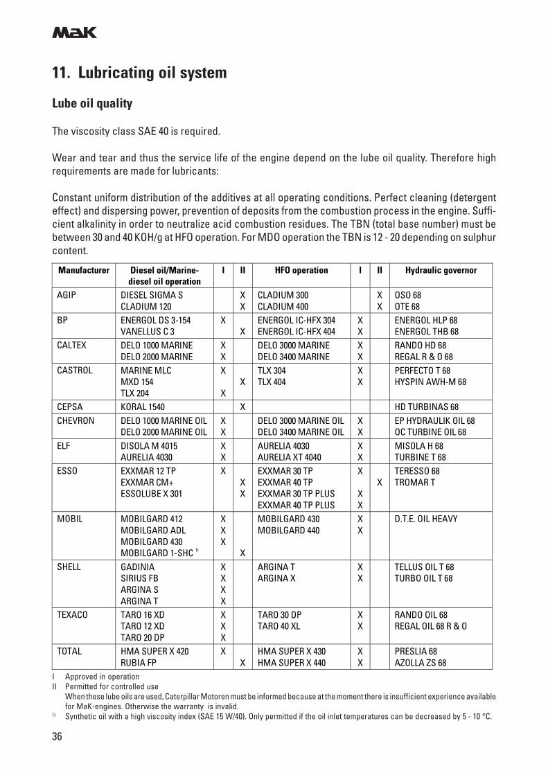
Lube oil quality
The viscosity class SAE 40 is required.
Wear and tear and thus the service life of the engine depend on the lube oil quality. Therefore highrequirements are made for lubricants:
Constant uniform distribution of the additives at all operating conditions. Perfect cleaning (detergenteffect) and dispersing power, prevention of deposits from the combustion process in the engine. Suffi-cient alkalinity in order to neutralize acid combustion residues. The TBN (total base number) must bebetween 30 and 40 KOH/g at HFO operation. For MDO operation the TBN is 12 - 20 depending on sulphurcontent.
I Approved in operationII Permitted for controlled use
When these lube oils are used, Caterpillar Motoren must be informed because at the moment there is insufficient experience availablefor MaK-engines. Otherwise the warranty is invalid.
1) Synthetic oil with a high viscosity index (SAE 15 W/40). Only permitted if the oil inlet temperatures can be decreased by 5 - 10 °C.
Manufacturer Diesel oil/Marine-diesel oil operation
I II HFO operation I II Hydraulic governor
AGIP DIESEL SIGMA S CLADIUM 120
X X
CLADIUM 300 CLADIUM 400
X X
OSO 68 OTE 68
BP ENERGOL DS 3-154 VANELLUS C 3
X X
ENERGOL IC-HFX 304 ENERGOL IC-HFX 404
X X
ENERGOL HLP 68 ENERGOL THB 68
CALTEX DELO 1000 MARINE DELO 2000 MARINE
X X
DELO 3000 MARINE DELO 3400 MARINE
X X
RANDO HD 68 REGAL R & O 68
CASTROL MARINE MLC MXD 154 TLX 204
X
X
X
TLX 304 TLX 404
X X
PERFECTO T 68 HYSPIN AWH-M 68
CEPSA KORAL 1540 X HD TURBINAS 68 CHEVRON DELO 1000 MARINE OIL
DELO 2000 MARINE OIL X X
DELO 3000 MARINE OIL DELO 3400 MARINE OIL
X X
EP HYDRAULIK OIL 68 OC TURBINE OIL 68
ELF DISOLA M 4015 AURELIA 4030
X X
AURELIA 4030 AURELIA XT 4040
X X
MISOLA H 68 TURBINE T 68
ESSO EXXMAR 12 TP EXXMAR CM+ ESSOLUBE X 301
X X X
EXXMAR 30 TP EXXMAR 40 TP EXXMAR 30 TP PLUS EXXMAR 40 TP PLUS
X
X X
X
TERESSO 68 TROMAR T
MOBIL MOBILGARD 412 MOBILGARD ADL MOBILGARD 430 MOBILGARD 1-SHC 1)
X X X
X
MOBILGARD 430 MOBILGARD 440
X X
D.T.E. OIL HEAVY
SHELL GADINIA SIRIUS FB ARGINA S ARGINA T
X X X X
ARGINA T ARGINA X
X X
TELLUS OIL T 68 TURBO OIL T 68
TEXACO TARO 16 XD TARO 12 XD TARO 20 DP
X X X
TARO 30 DP TARO 40 XL
X X
RANDO OIL 68 REGAL OIL 68 R & O
TOTAL HMA SUPER X 420 RUBIA FP
X X
HMA SUPER X 430 HMA SUPER X 440
X X
PRESLIA 68 AZOLLA ZS 68
m
37
11. Lubricating oil system
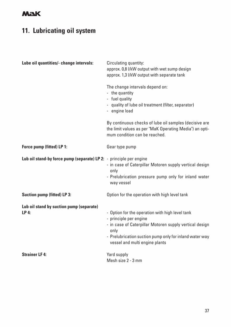
Lube oil quantities/- change intervals: Circulating quantity:approx. 0,8 l/kW output with wet sump designapprox. 1,3 l/kW output with separate tank
The change intervals depend on:- the quantity- fuel quality- quality of lube oil treatment (filter, separator)- engine load
By continuous checks of lube oil samples (decisive arethe limit values as per "MaK Operating Media") an opti-mum condition can be reached.
Force pump (fitted) LP 1: Gear type pump
Lub oil stand-by force pump (separate) LP 2: - principle per engine- in case of Caterpillar Motoren supply vertical design
only- Prelubrication pressure pump only for inland water
way vessel
Suction pump (fitted) LP 3: Option for the operation with high level tank
Lub oil stand by suction pump (separate)LP 4: - Option for the operation with high level tank
- principle per engine- in case of Caterpillar Motoren supply vertical design
only- Prelubrication suction pump only for inland water way
vessel and multi engine plants
Strainer LF 4: Yard supplyMesh size 2 - 3 mm
m
38
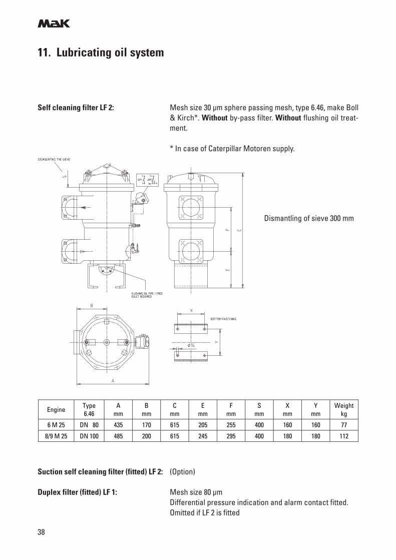
Self cleaning filter LF 2: Mesh size 30 µm sphere passing mesh, type 6.46, make Boll& Kirch*. Without by-pass filter. Without flushing oil treat-ment.
* In case of Caterpillar Motoren supply.
11. Lubricating oil system
Dismantling of sieve 300 mm
Engine Type 6.46
A mm
B mm
C mm
E mm
F mm
S mm
X mm
Y mm
Weight kg
6 M 25 DN 80 435 170 615 205 255 400 160 160 77
8/9 M 25 DN 100 485 200 615 245 295 400 180 180 112
Suction self cleaning filter (fitted) LF 2: (Option)
Duplex filter (fitted) LF 1: Mesh size 80 µmDifferential pressure indication and alarm contact fitted.Omitted if LF 2 is fitted
m
39
11. Lubricating oil system
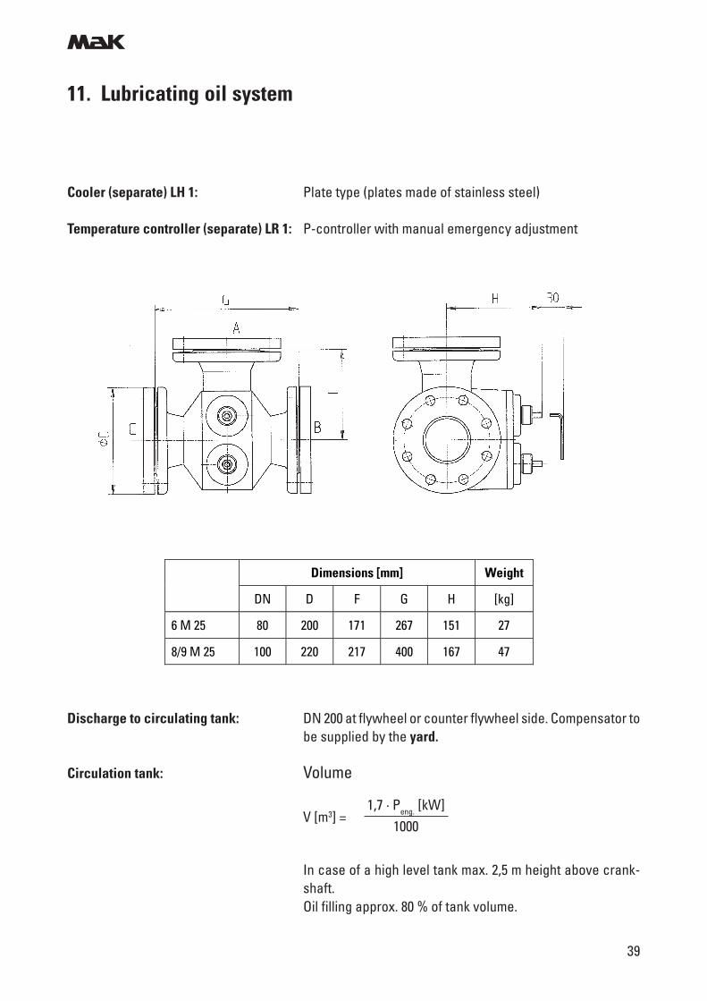
Cooler (separate) LH 1: Plate type (plates made of stainless steel)
Temperature controller (separate) LR 1: P-controller with manual emergency adjustment
Dimensions [mm] Weight
DN D F G H [kg]
6 M 25 80 200 171 267 151 27
8/9 M 25 100 220 217 400 167 47
Discharge to circulating tank: DN 200 at flywheel or counter flywheel side. Compensator tobe supplied by the yard.
Circulation tank: Volume
In case of a high level tank max. 2,5 m height above crank-shaft.Oil filling approx. 80 % of tank volume.
V [m3] =1,7 · Peng. [kW]
1000
m
40
11. Lubricating oil system
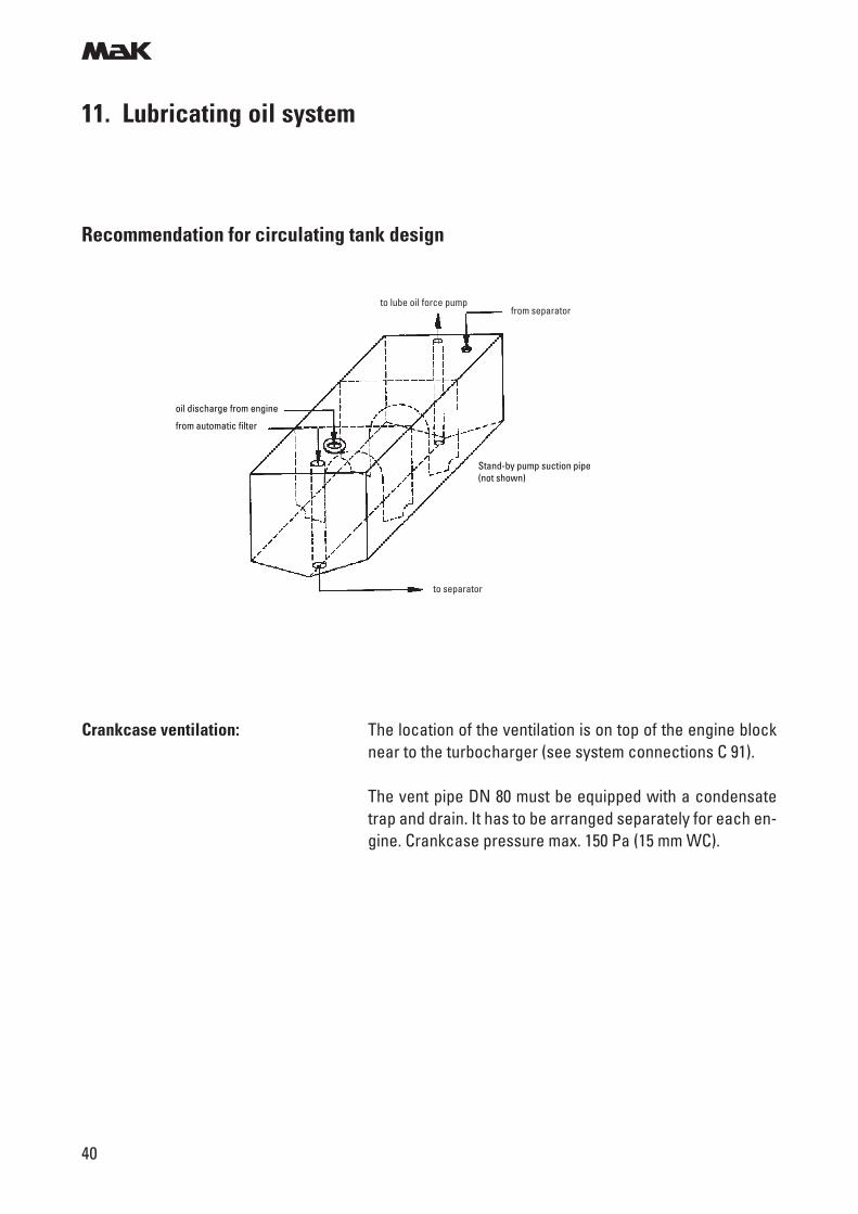
Recommendation for circulating tank design
Crankcase ventilation: The location of the ventilation is on top of the engine blocknear to the turbocharger (see system connections C 91).
The vent pipe DN 80 must be equipped with a condensatetrap and drain. It has to be arranged separately for each en-gine. Crankcase pressure max. 150 Pa (15 mm WC).
Stand-by pump suction pipe(not shown)
to separator
oil discharge from engine
from automatic filter
to lube oil force pumpfrom separator
m
41
Treatment at gas oil/MDO operation
The service life of the lube oil will be extended by by-passtreatment.
Centrifuge (Option, fitted on the engine)LS 2: Minimum requirement
Separator LS 1: RecommendedDesign:- Separating temperature 85 - 95 °C- Quantity to be cleaned three times/day- Utilization 20 %- Self cleaning type
Rated capacity
VN [l/h] = 0,89 · Peng [kW]
Treatment at heavy fuel operation
Separator LS 1: Required with the following design:- Separating temperature 95 °C- Quantity to be cleaned five times/day- Utilization 20 %- Self cleaning type
Rated capacity
VN [l/h] = 1,45 · Peng [kW]
11. Lubricating oil system
m
42
11. Lubricating oil systemGasoil/MDO operation (wet sump)
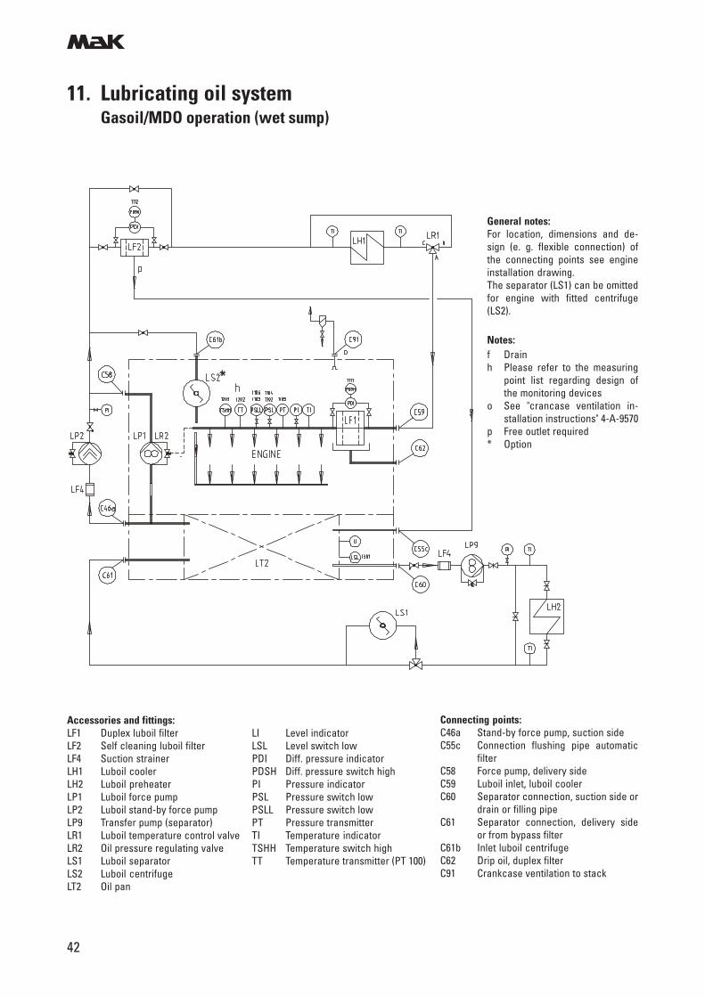
Connecting points:C46a Stand-by force pump, suction sideC55c Connection flushing pipe automatic
filterC58 Force pump, delivery sideC59 Luboil inlet, luboil coolerC60 Separator connection, suction side or
drain or filling pipeC61 Separator connection, delivery side
or from bypass filterC61b Inlet luboil centrifugeC62 Drip oil, duplex filterC91 Crankcase ventilation to stack
Accessories and fittings:LF1 Duplex luboil filter LI Level indicatorLF2 Self cleaning luboil filter LSL Level switch lowLF4 Suction strainer PDI Diff. pressure indicatorLH1 Luboil cooler PDSH Diff. pressure switch highLH2 Luboil preheater PI Pressure indicatorLP1 Luboil force pump PSL Pressure switch lowLP2 Luboil stand-by force pump PSLL Pressure switch lowLP9 Transfer pump (separator) PT Pressure transmitterLR1 Luboil temperature control valve TI Temperature indicatorLR2 Oil pressure regulating valve TSHH Temperature switch highLS1 Luboil separator TT Temperature transmitter (PT 100)LS2 Luboil centrifugeLT2 Oil pan
General notes:For location, dimensions and de-sign (e. g. flexible connection) ofthe connecting points see engineinstallation drawing.The separator (LS1) can be omittedfor engine with fitted centrifuge(LS2).
Notes:f Drainh Please refer to the measuring
point list regarding design ofthe monitoring devices
o See "crancase ventilation in-stallation instructions" 4-A-9570
p Free outlet required* Option
m
43
11. Lubricating oil systemGasoil/MDO operation (dry sump)
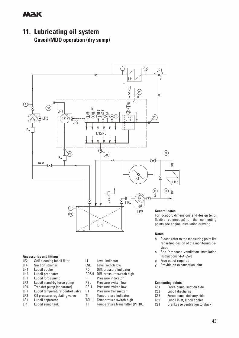
Connecting points:C51 Force pump, suction sideC53 Luboil dischargeC58 Force pump, delivery sideC59 Luboil inlet, luboil coolerC91 Crankcase ventilation to stack
Accessories and fittings:LF2 Self cleaning luboil filter LI Level indicatorLF4 Suction strainer LSL Level switch lowLH1 Luboil cooler PDI Diff. pressure indicatorLH2 Luboil preheater PDSH Diff. pressure switch highLP1 Luboil force pump PI Pressure indicatorLP2 Luboil stand-by force pump PSL Pressure switch lowLP9 Transfer pump (separator) PSLL Pressure switch lowLR1 Luboil temperature control valve PT Pressure transmitterLR2 Oil pressure regulating valve TI Temperature indicatorLS1 Luboil separator TSHH Temperature switch highLT1 Luboil sump tank TT Temperature transmitter (PT 100)
General notes:For location, dimensions and design (e. g.flexible connection) of the connectingpoints see engine installation drawing.
Notes:h Please refer to the measuring point list
regarding design of the monitoring de-vices
o See "crancase ventilation installationinstructions" 4-A-9570
p Free outlet requiredy Provide an expansation joint
m
44
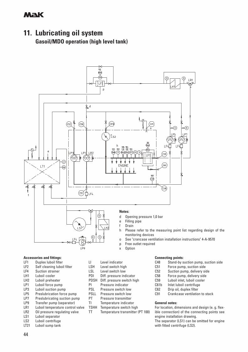
11. Lubricating oil systemGasoil/MDO operation (high level tank)
Connecting points:C48 Stand-by suction pump, suction sideC51 Force pump, suction sideC52 Suction pump, delivery sideC58 Force pump, delivery sideC59 Luboil inlet, luboil coolerC61b Inlet luboil centrifugeC62 Drip oil, duplex filterC91 Crankcase ventilation to stack
General notes:For location, dimensions and design (e. g. flex-ible connection) of the connecting points seeengine installation drawing.The separator (LS1) can be omitted for enginewith fitted centrifuge (LS2).
Accessories and fittings:LF1 Duplex luboil filter LI Level indicatorLF2 Self cleaning luboil filter LSH Level switch highLF4 Suction strainer LSL Level switch lowLH1 Luboil cooler PDI Diff. pressure indicatorLH2 Luboil preheater PDSH Diff. pressure switch highLP1 Luboil force pump PI Pressure indicatorLP3 Luboil suction pump PSL Pressure switch lowLP5 Preslubrication force pump PSLL Pressure switch lowLP7 Preslubricating suction pump PT Pressure transmitterLP9 Transfer pump (separator) TI Temperature indicatorLR1 Luboil temperature control valve TSHH Temperature switch highLR2 Oil pressure regulating valve TT Temperature transmitter (PT 100)LS1 Luboil separatorLS2 Luboil centrifugeLT21 Luboil sump tank
Notes:d Opening pressure 1,0 bare Filling pipef Drainh Please refer to the measuring point list regarding design of the
monitoring deviceso See "crancase ventilation installation instructions" 4-A-9570p Free outlet requiredx Option
m
45
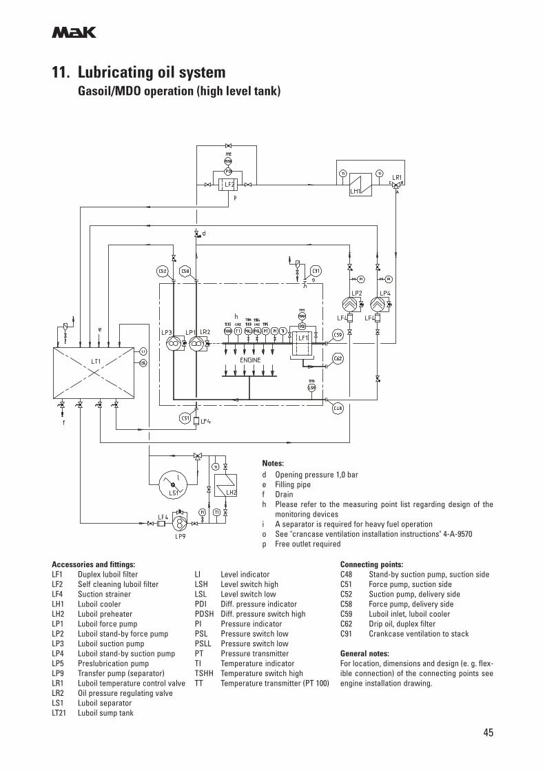
11. Lubricating oil systemGasoil/MDO operation (high level tank)
Connecting points:C48 Stand-by suction pump, suction sideC51 Force pump, suction sideC52 Suction pump, delivery sideC58 Force pump, delivery sideC59 Luboil inlet, luboil coolerC62 Drip oil, duplex filterC91 Crankcase ventilation to stack
General notes:For location, dimensions and design (e. g. flex-ible connection) of the connecting points seeengine installation drawing.
Accessories and fittings:LF1 Duplex luboil filter LI Level indicatorLF2 Self cleaning luboil filter LSH Level switch highLF4 Suction strainer LSL Level switch lowLH1 Luboil cooler PDI Diff. pressure indicatorLH2 Luboil preheater PDSH Diff. pressure switch highLP1 Luboil force pump PI Pressure indicatorLP2 Luboil stand-by force pump PSL Pressure switch lowLP3 Luboil suction pump PSLL Pressure switch lowLP4 Luboil stand-by suction pump PT Pressure transmitterLP5 Preslubrication pump TI Temperature indicatorLP9 Transfer pump (separator) TSHH Temperature switch highLR1 Luboil temperature control valve TT Temperature transmitter (PT 100)LR2 Oil pressure regulating valveLS1 Luboil separatorLT21 Luboil sump tank
Notes:d Opening pressure 1,0 bare Filling pipef Drainh Please refer to the measuring point list regarding design of the
monitoring devicesi A separator is required for heavy fuel operationo See "crancase ventilation installation instructions" 4-A-9570p Free outlet required
m
46
12. Cooling water system
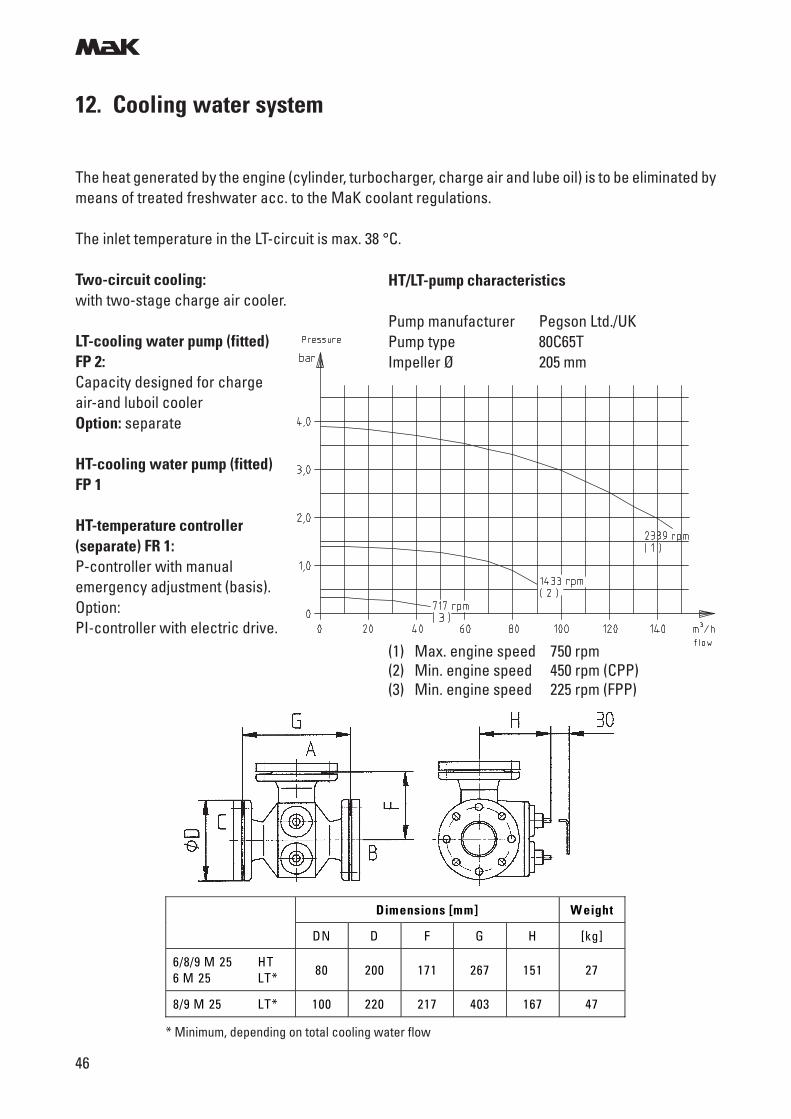
Dimensions [mm] W eight
DN D F G H [kg]
6/8/9 M 25 HT 6 M 25 LT* 80 200 171 267 151 27
8/9 M 25 LT* 100 220 217 403 167 47
The heat generated by the engine (cylinder, turbocharger, charge air and lube oil) is to be eliminated bymeans of treated freshwater acc. to the MaK coolant regulations.
The inlet temperature in the LT-circuit is max. 38 °C.
Two-circuit cooling:with two-stage charge air cooler.
LT-cooling water pump (fitted)FP 2:Capacity designed for chargeair-and luboil coolerOption: separate
HT-cooling water pump (fitted)FP 1
HT-temperature controller(separate) FR 1:P-controller with manualemergency adjustment (basis).Option:PI-controller with electric drive.
* Minimum, depending on total cooling water flow
(1) Max. engine speed 750 rpm(2) Min. engine speed 450 rpm (CPP)(3) Min. engine speed 225 rpm (FPP)
HT/LT-pump characteristics
Pump manufacturer Pegson Ltd./UKPump type 80C65TImpeller Ø 205 mm
m
47
12. Cooling water system
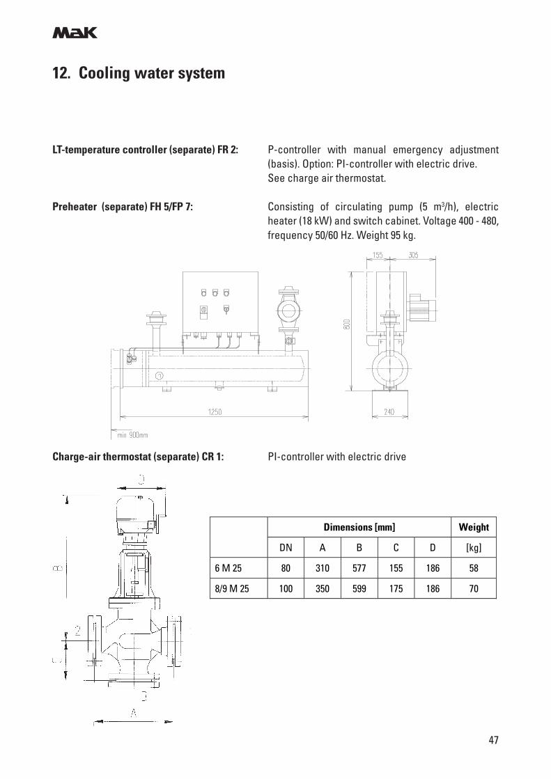
Dimensions [mm] Weight
DN A B C D [kg]
6 M 25 80 310 577 155 186 58
8/9 M 25 100 350 599 175 186 70
LT-temperature controller (separate) FR 2: P-controller with manual emergency adjustment(basis). Option: PI-controller with electric drive.See charge air thermostat.
Preheater (separate) FH 5/FP 7: Consisting of circulating pump (5 m3/h), electricheater (18 kW) and switch cabinet. Voltage 400 - 480,frequency 50/60 Hz. Weight 95 kg.
Charge-air thermostat (separate) CR 1: PI-controller with electric drive
m
48
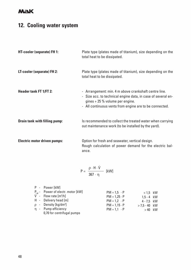
ρ · H · VP = [kW]
367 · η
.
P - Power [kW]PM - Power of electr. motor [kW]V - Flow rate [m3/h]H - Delivery head [m]ρ - Density [kg/dm3]η - Pump efficiency
0,70 for centrifugal pumps
< 1,5 kW1,5 - 4 kW4 - 7,5 kW
> 7,5 - 40 kW> 40 kW
PM = 1,5 · PPM = 1,25 · PPM = 1,2 · PPM = 1,15 · PPM = 1,1 · P
.
HT-cooler (separate) FH 1: Plate type (plates made of titanium), size depending on thetotal heat to be dissipated.
LT-cooler (separate) FH 2: Plate type (plates made of titanium), size depending on thetotal heat to be dissipated.
Header tank FT 1/FT 2: - Arrangement: min. 4 m above crankshaft centre line.- Size acc. to technical engine data, in case of several en-
gines + 25 % volume per engine.- All continuous vents from engine are to be connected.
Drain tank with filling pump: Is recommended to collect the treated water when carryingout maintenance work (to be installed by the yard).
Electric motor driven pumps: Option for fresh and seawater, vertical design.Rough calculation of power demand for the electric bal-ance.
12. Cooling water system
m
49
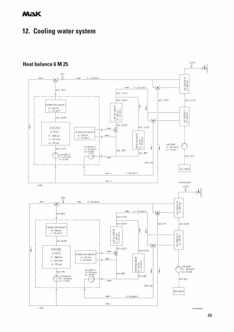
12. Cooling water system
Heat balance 6 M 25
m
50
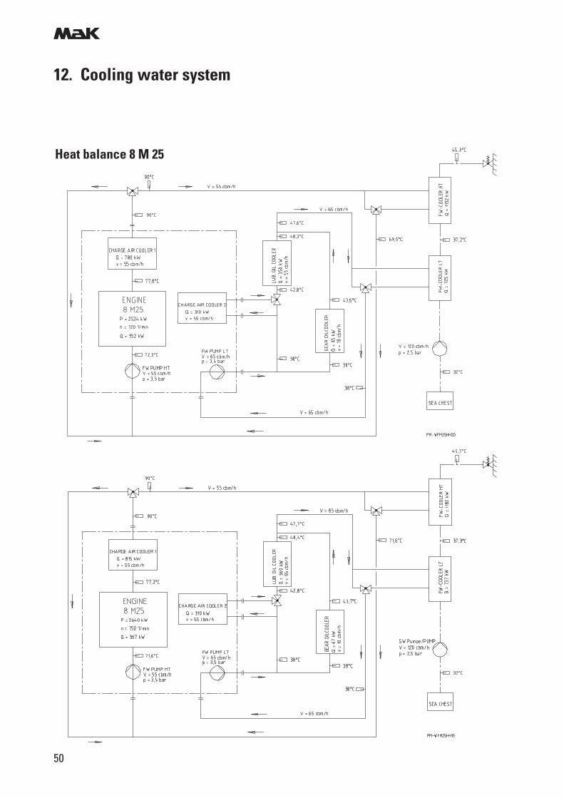
12. Cooling water system
Heat balance 8 M 25
m
51
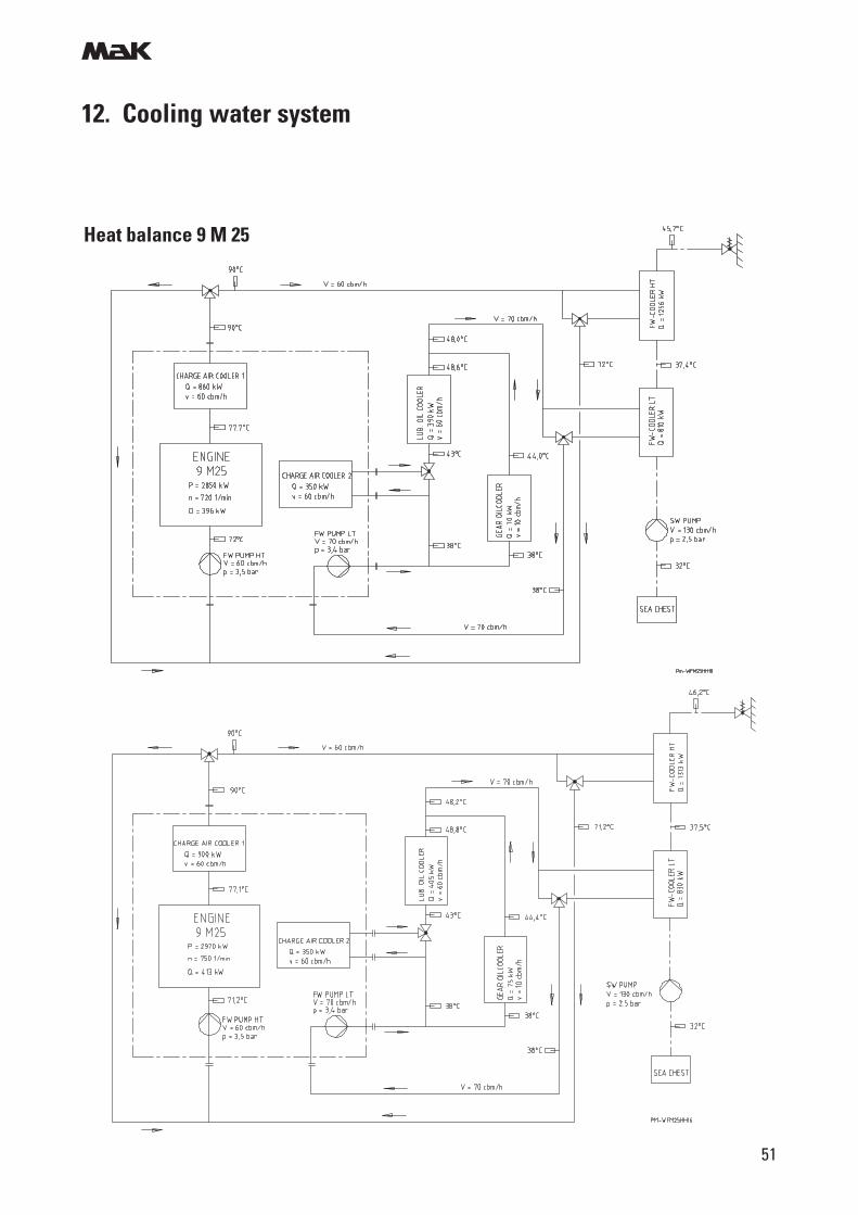
12. Cooling water system
Heat balance 9 M 25
m
52
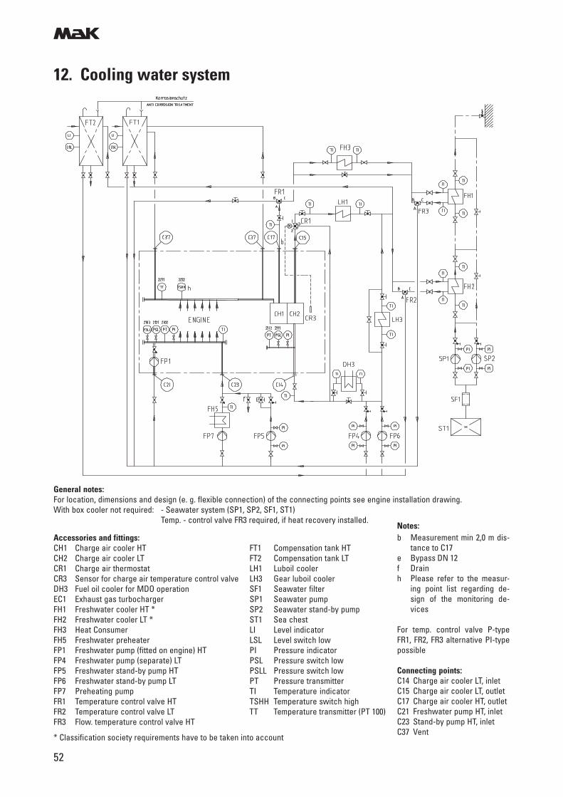
12. Cooling water system
Notes:b Measurement min 2,0 m dis-
tance to C17e Bypass DN 12f Drainh Please refer to the measur-
ing point list regarding de-sign of the monitoring de-vices
For temp. control valve P-typeFR1, FR2, FR3 alternative PI-typepossible
Connecting points:C14 Charge air cooler LT, inletC15 Charge air cooler LT, outletC17 Charge air cooler HT, outletC21 Freshwater pump HT, inletC23 Stand-by pump HT, inletC37 Vent
Accessories and fittings:CH1 Charge air cooler HT FT1 Compensation tank HTCH2 Charge air cooler LT FT2 Compensation tank LTCR1 Charge air thermostat LH1 Luboil coolerCR3 Sensor for charge air temperature control valve LH3 Gear luboil coolerDH3 Fuel oil cooler for MDO operation SF1 Seawater filterEC1 Exhaust gas turbocharger SP1 Seawater pumpFH1 Freshwater cooler HT * SP2 Seawater stand-by pumpFH2 Freshwater cooler LT * ST1 Sea chestFH3 Heat Consumer LI Level indicatorFH5 Freshwater preheater LSL Level switch lowFP1 Freshwater pump (fitted on engine) HT PI Pressure indicatorFP4 Freshwater pump (separate) LT PSL Pressure switch lowFP5 Freshwater stand-by pump HT PSLL Pressure switch lowFP6 Freshwater stand-by pump LT PT Pressure transmitterFP7 Preheating pump TI Temperature indicatorFR1 Temperature control valve HT TSHH Temperature switch highFR2 Temperature control valve LT TT Temperature transmitter (PT 100)FR3 Flow. temperature control valve HT
* Classification society requirements have to be taken into account
General notes:For location, dimensions and design (e. g. flexible connection) of the connecting points see engine installation drawing.With box cooler not required: - Seawater system (SP1, SP2, SF1, ST1)
Temp. - control valve FR3 required, if heat recovery installed.
m
53
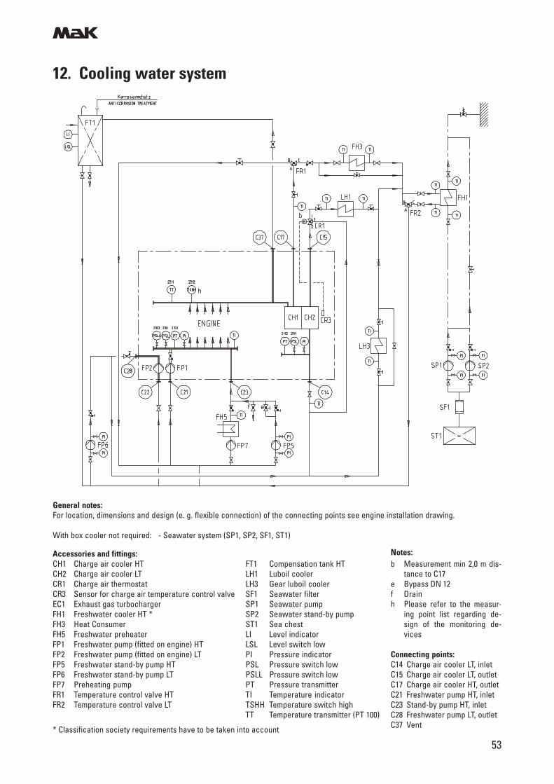
12. Cooling water system
Notes:b Measurement min 2,0 m dis-
tance to C17e Bypass DN 12f Drainh Please refer to the measur-
ing point list regarding de-sign of the monitoring de-vices
Connecting points:C14 Charge air cooler LT, inletC15 Charge air cooler LT, outletC17 Charge air cooler HT, outletC21 Freshwater pump HT, inletC23 Stand-by pump HT, inletC28 Freshwater pump LT, outletC37 Vent
Accessories and fittings:CH1 Charge air cooler HT FT1 Compensation tank HTCH2 Charge air cooler LT LH1 Luboil coolerCR1 Charge air thermostat LH3 Gear luboil coolerCR3 Sensor for charge air temperature control valve SF1 Seawater filterEC1 Exhaust gas turbocharger SP1 Seawater pumpFH1 Freshwater cooler HT * SP2 Seawater stand-by pumpFH3 Heat Consumer ST1 Sea chestFH5 Freshwater preheater LI Level indicatorFP1 Freshwater pump (fitted on engine) HT LSL Level switch lowFP2 Freshwater pump (fitted on engine) LT PI Pressure indicatorFP5 Freshwater stand-by pump HT PSL Pressure switch lowFP6 Freshwater stand-by pump LT PSLL Pressure switch lowFP7 Preheating pump PT Pressure transmitterFR1 Temperature control valve HT TI Temperature indicatorFR2 Temperature control valve LT TSHH Temperature switch high
TT Temperature transmitter (PT 100)
* Classification society requirements have to be taken into account
General notes:For location, dimensions and design (e. g. flexible connection) of the connecting points see engine installation drawing.
With box cooler not required: - Seawater system (SP1, SP2, SF1, ST1)
m
54
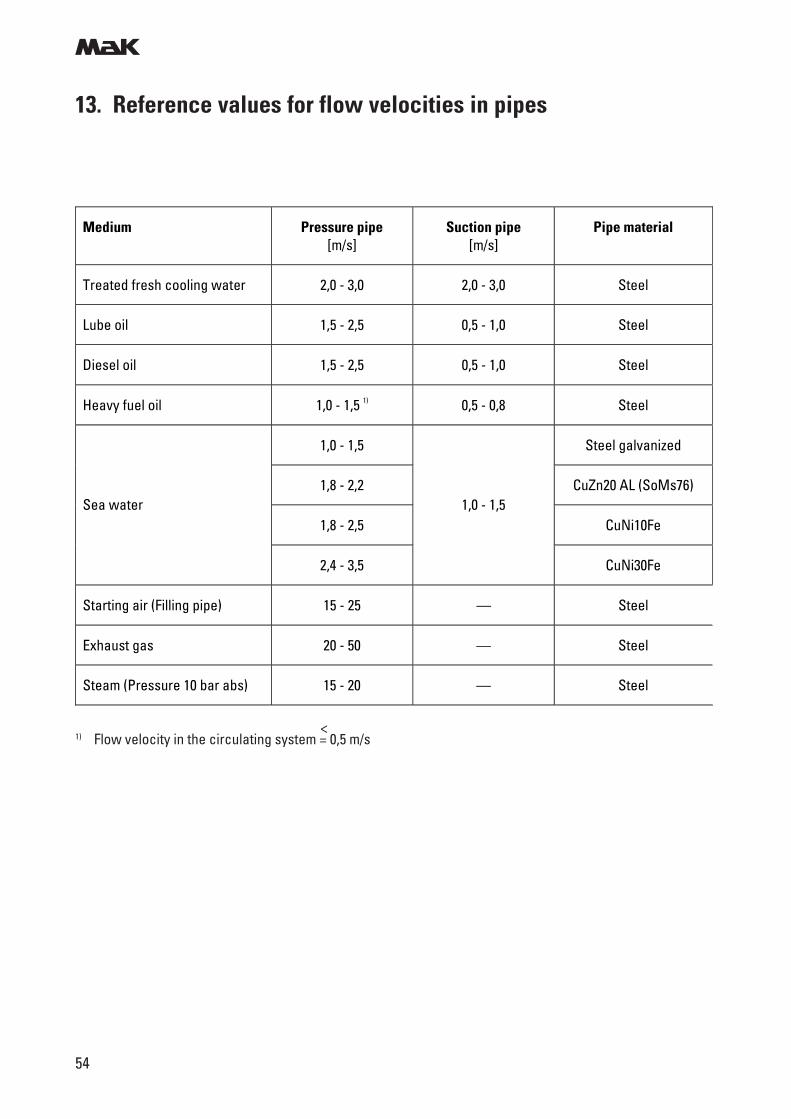
13. Reference values for flow velocities in pipes
Medium Pressure pipe [m/s]
Suction pipe [m/s]
Pipe material
Treated fresh cooling water 2,0 - 3,0 2,0 - 3,0 Steel
Lube oil 1,5 - 2,5 0,5 - 1,0 Steel
Diesel oil 1,5 - 2,5 0,5 - 1,0 Steel
Heavy fuel oil 1,0 - 1,5 1) 0,5 - 0,8 Steel
1,0 - 1,5 Steel galvanized
1,8 - 2,2 CuZn20 AL (SoMs76)
1,8 - 2,5 CuNi10Fe Sea water
2,4 - 3,5
1,0 - 1,5
CuNi30Fe
Starting air (Filling pipe) 15 - 25 — Steel
Exhaust gas 20 - 50 — Steel
Steam (Pressure 10 bar abs) 15 - 20 — Steel
1) Flow velocity in the circulating system = 0,5 m/s
<
m
55
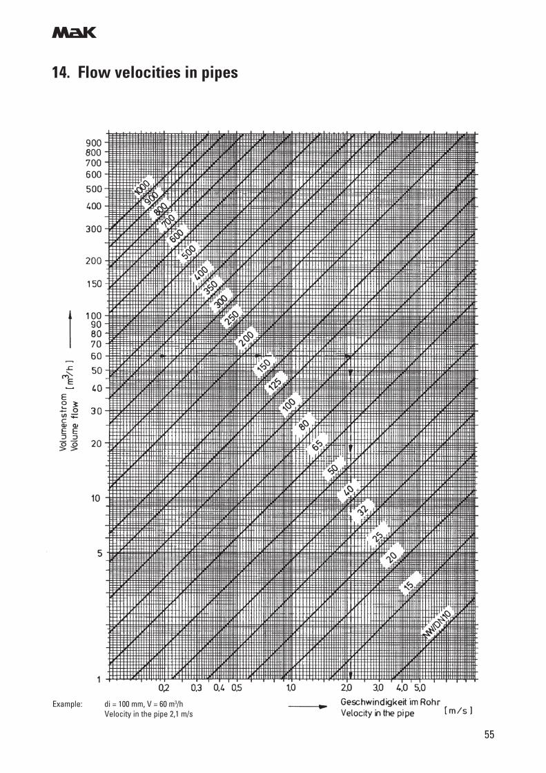
14. Flow velocities in pipes
Example: di = 100 mm, V = 60 m3/hVelocity in the pipe 2,1 m/s
m
56
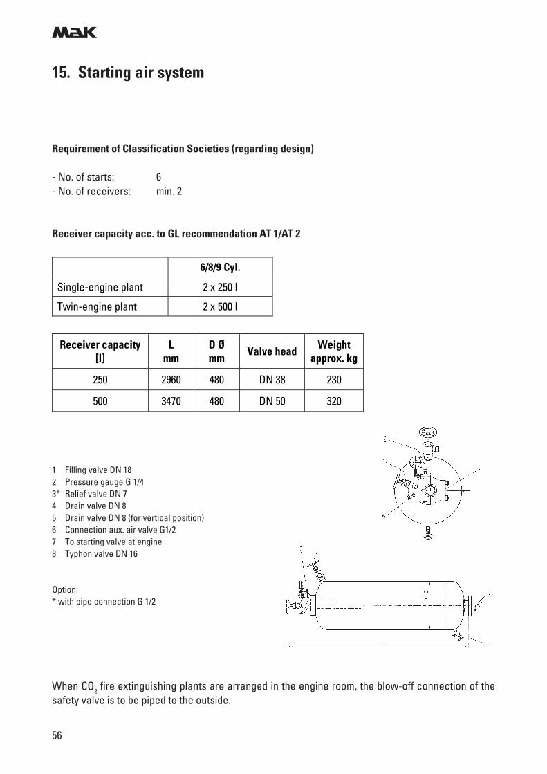
15. Starting air system
Requirement of Classification Societies (regarding design)
- No. of starts: 6- No. of receivers: min. 2
Receiver capacity acc. to GL recommendation AT 1/AT 2
When CO2 fire extinguishing plants are arranged in the engine room, the blow-off connection of thesafety valve is to be piped to the outside.
1 Filling valve DN 182 Pressure gauge G 1/43* Relief valve DN 74 Drain valve DN 85 Drain valve DN 8 (for vertical position)6 Connection aux. air valve G1/27 To starting valve at engine8 Typhon valve DN 16
Option:* with pipe connection G 1/2
6/8/9 Cyl.
Single-engine plant 2 x 250 l
Twin-engine plant 2 x 500 l
Receiver capacity [l]
L mm
D Ø mm
Valve head Weight
approx. kg
250 2960 480 DN 38 230
500 3470 480 DN 50 320
m
57
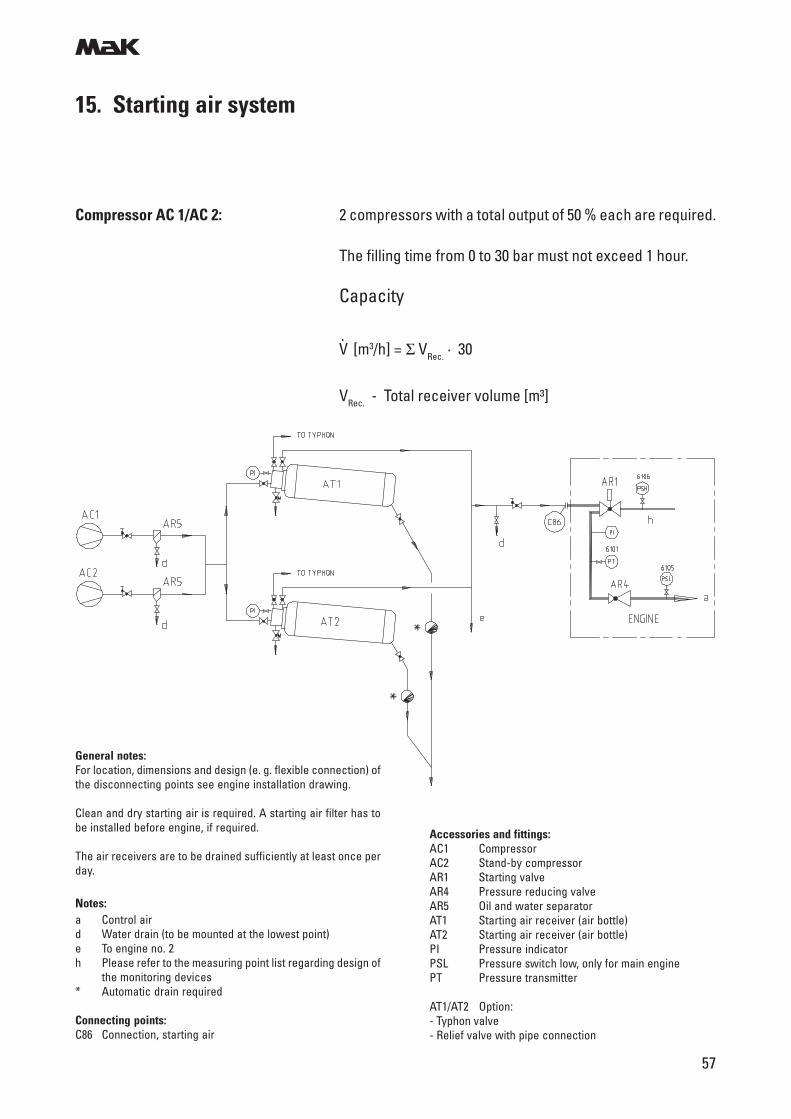
15. Starting air system
Compressor AC 1/AC 2: 2 compressors with a total output of 50 % each are required.
The filling time from 0 to 30 bar must not exceed 1 hour.
Capacity
V [m3/h] = Σ VRec. · 30.
VRec. - Total receiver volume [m³]
General notes:For location, dimensions and design (e. g. flexible connection) ofthe disconnecting points see engine installation drawing.
Clean and dry starting air is required. A starting air filter has tobe installed before engine, if required.
The air receivers are to be drained sufficiently at least once perday.
Notes:a Control aird Water drain (to be mounted at the lowest point)e To engine no. 2h Please refer to the measuring point list regarding design of
the monitoring devices* Automatic drain required
Connecting points:C86 Connection, starting air
Accessories and fittings:AC1 CompressorAC2 Stand-by compressorAR1 Starting valveAR4 Pressure reducing valveAR5 Oil and water separatorAT1 Starting air receiver (air bottle)AT2 Starting air receiver (air bottle)PI Pressure indicatorPSL Pressure switch low, only for main enginePT Pressure transmitter
AT1/AT2 Option:- Typhon valve- Relief valve with pipe connection
m
58
16. Combustion air system
General: To obtain good working conditions in the engine room and toensure trouble free operation of all equipment attentionshall be paid to the engine room ventilation and the supply ofcombustion air.
The combustion air required and the heat radiation of allconsumers/heat producers must be taken into account.
Air intake from engine room (standard): - Fans are to be designed for a slight overpressure in theengine room.
- On system side the penetration of water, sand, dust, andexhaust gas must be avoided.
- When operating under tropical conditions the air flowmust be conveyed directly to the turbocharger.
- The temperature at turbocharger filter should not fall be-low + 10 °C.
- In cold areas warming up of the air in the engine roommust be ensured.
Air intake from outside: - The intake air duct is to be provided with a filter. Penetra-tion of water, sand, dust and exhaust gas must beavoided.
- Connection to the turbocharger is to be established via anexpansion joint (to be supplied by the yard). For this pur-pose the turbocharger will be equipped with a connectionsocket.
- At temperatures below + 10 °C the Caterpillar Motoren/Application Engineering must be consulted.
- The max pressure loss (incl. silencer and exhaust gasboiler) of 30 mbar is applicable as value for the total flowresistance of plants with separate intake air filter!
Radiated heat: see technical dataTo dissipate the radiated heat a slight and evenly distributedair current is to be led along the engine exhaust gas mani-fold starting from the turbocharger.
Operation without turbocharger: Emergency operation with locked rotor possible at approx:- 20 % output, 100 % speed with controlable pitch propeller- 60 % speed with fixed pitch propeller- Heavy fuel operation to be avoided
m
59
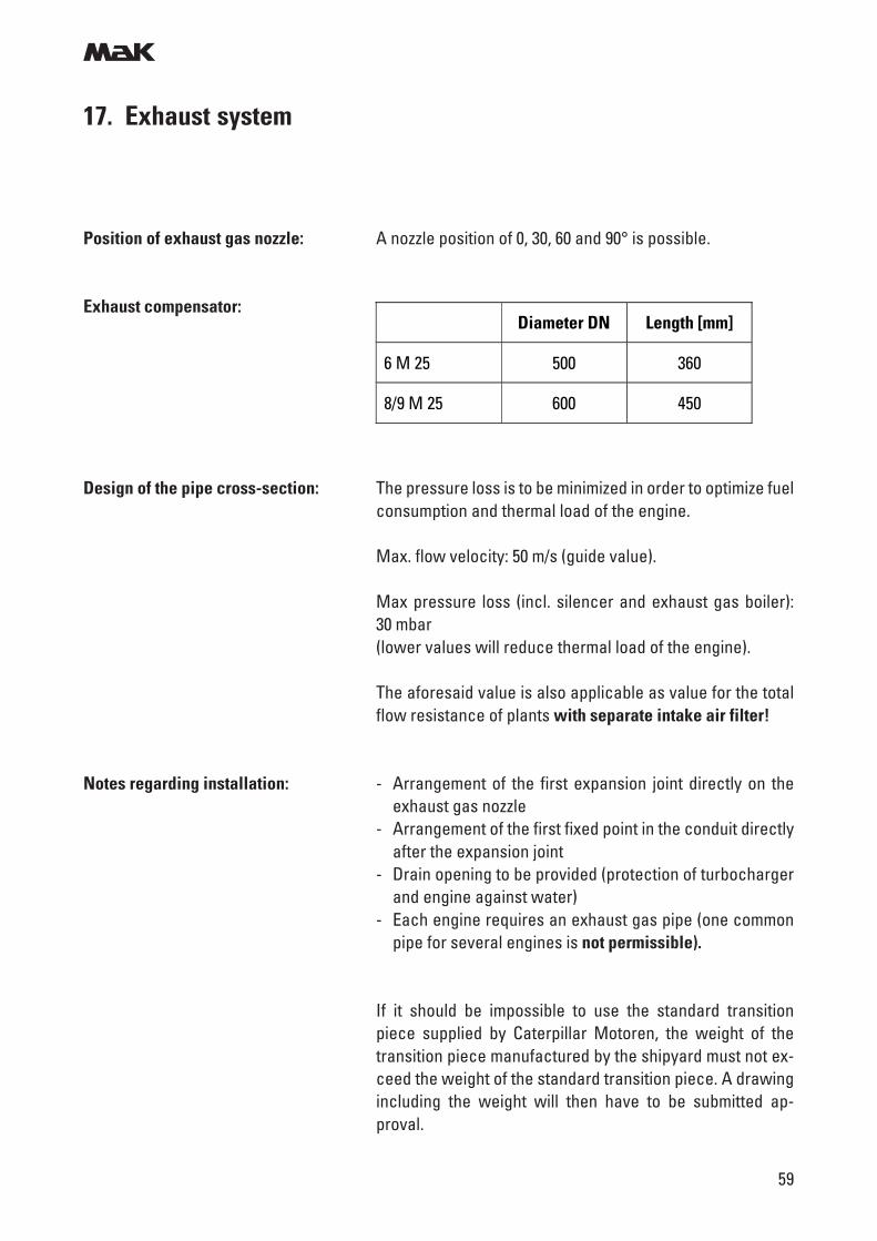
17. Exhaust system
Position of exhaust gas nozzle: A nozzle position of 0, 30, 60 and 90° is possible.
Exhaust compensator:
Design of the pipe cross-section: The pressure loss is to be minimized in order to optimize fuelconsumption and thermal load of the engine.
Max. flow velocity: 50 m/s (guide value).
Max pressure loss (incl. silencer and exhaust gas boiler):30 mbar(lower values will reduce thermal load of the engine).
The aforesaid value is also applicable as value for the totalflow resistance of plants with separate intake air filter!
Notes regarding installation: - Arrangement of the first expansion joint directly on theexhaust gas nozzle
- Arrangement of the first fixed point in the conduit directlyafter the expansion joint
- Drain opening to be provided (protection of turbochargerand engine against water)
- Each engine requires an exhaust gas pipe (one commonpipe for several engines is not permissible).
If it should be impossible to use the standard transitionpiece supplied by Caterpillar Motoren, the weight of thetransition piece manufactured by the shipyard must not ex-ceed the weight of the standard transition piece. A drawingincluding the weight will then have to be submitted ap-proval.
Diameter DN Length [mm]
6 M 25 500 360
8/9 M 25 600 450
m
60
17. Exhaust system
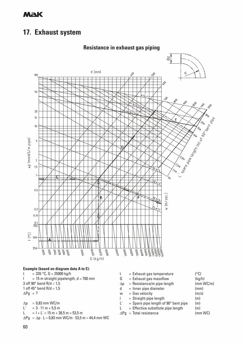
t = Exhaust gas temperature (°C)G = Exhaust gas massflow (kg/h)∆p = Resistance/m pipe length (mm WC/m)d = Inner pipe diameter (mm)w = Gas velocity (m/s)l = Straight pipe length (m)L' = Spare pipe length of 90° bent pipe (m)L = Effective substitute pipe length (m)∆Pg = Total resistance (mm WC)
Example (based on diagram data A to E):t = 335 °C, G = 25000 kg/hl = 15 m straight pipelength, d = 700 mm3 off 90° bend R/d = 1,51 off 45° bend R/d = 1,5∆Pg = ?
∆p = 0,83 mm WC/mL' = 3 · 11 m + 5,5 mL = l + L' = 15 m + 38,5 m = 53,5 m∆Pg = ∆p · L = 0,83 mm WC/m · 53,5 m = 44,4 mm WC
Resistance in exhaust gas piping
m
61
17. Exhaust system
0.031 0.063 0.125 0.25 0.5 1 2 4 8 f [kHz]
160
150
140
130
120
110
100
140 140 139135
133 132 131126
123
0.031 0.063 0.125 0.25 0.5 1 2 4 8 f [kHz]
160
150
140
130
120
110
100
140 139 139134
133 132 130125
122
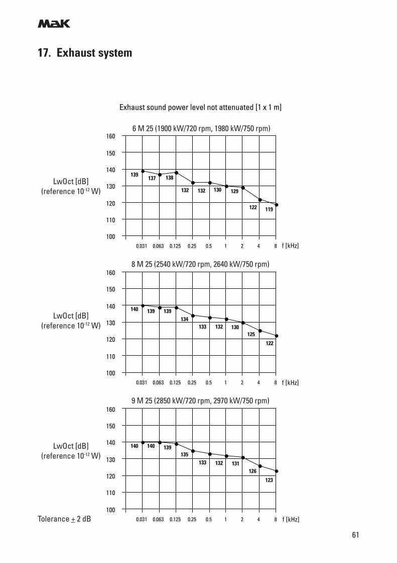
Exhaust sound power level not attenuated [1 x 1 m]
Tolerance + 2 dB
LwOct [dB](reference 10-12 W)
LwOct [dB](reference 10-12 W)
LwOct [dB](reference 10-12 W)
6 M 25 (1900 kW/720 rpm, 1980 kW/750 rpm)
9 M 25 (2850 kW/720 rpm, 2970 kW/750 rpm)
8 M 25 (2540 kW/720 rpm, 2640 kW/750 rpm)
0.031 0.063 0.125 0.25 0.5 1 2 4 8 f [kHz]
160
150
140
130
120
110
100
139137 138
132 132 130 129
122 119
m
62
17. Exhaust system
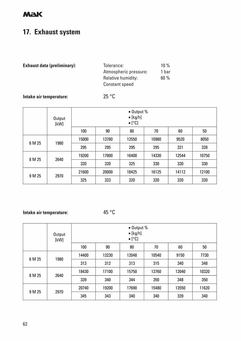
Exhaust data (preliminary): Tolerance: 10 %Atmospheric pressure: 1 barRelative humidity: 60 %Constant speed
Intake air temperature: 25 °C
Intake air temperature: 45 °C
• Output % • [kg/h] • [°C] Output
[kW]
100 90 80 70 60 50
15000 13780 12550 10980 9520 8050 6 M 25 1980
295 295 295 295 321 328
19200 17800 16400 14330 12544 10750 8 M 25 2640
320 320 325 330 330 330
21600 20000 18425 16125 14112 12100 9 M 25 2970
325 323 320 320 320 320
• Output % • [kg/h] • [°C] Output
[kW]
100 90 80 70 60 50
14400 13230 12048 10540 9150 7730 6 M 25 1980
313 312 313 315 340 348
18430 17100 15750 13760 12040 10320 8 M 25 2640
339 340 344 350 348 350
20740 19200 17690 15480 13550 11620 9 M 25 2970
345 343 340 340 339 340
m
63
17. Exhaust system
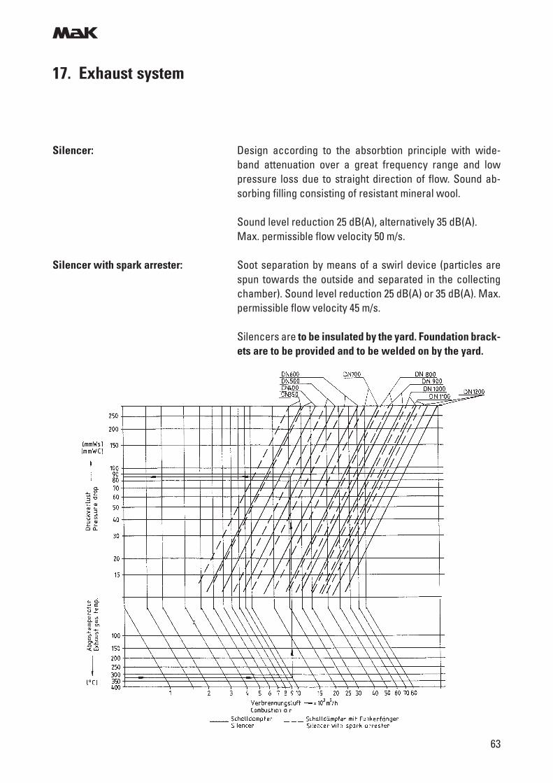
Silencer: Design according to the absorbtion principle with wide-band attenuation over a great frequency range and lowpressure loss due to straight direction of flow. Sound ab-sorbing filling consisting of resistant mineral wool.
Sound level reduction 25 dB(A), alternatively 35 dB(A).Max. permissible flow velocity 50 m/s.
Silencer with spark arrester: Soot separation by means of a swirl device (particles arespun towards the outside and separated in the collectingchamber). Sound level reduction 25 dB(A) or 35 dB(A). Max.permissible flow velocity 45 m/s.
Silencers are to be insulated by the yard. Foundation brack-ets are to be provided and to be welded on by the yard.
m
64
17. Exhaust system
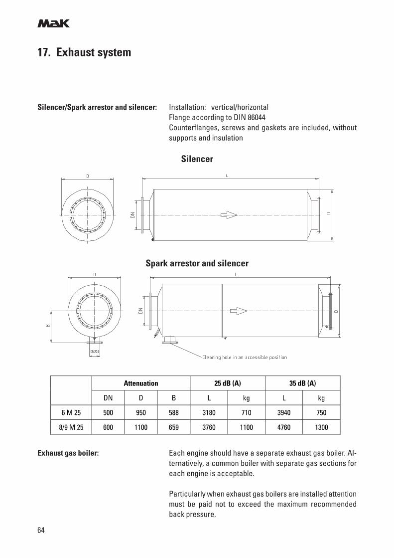
Silencer/Spark arrestor and silencer: Installation: vertical/horizontalFlange according to DIN 86044Counterflanges, screws and gaskets are included, withoutsupports and insulation
Silencer
Spark arrestor and silencer
Attenuation 25 dB (A) 35 dB (A)
DN D B L kg L kg
6 M 25 500 950 588 3180 710 3940 750
8/9 M 25 600 1100 659 3760 1100 4760 1300
Exhaust gas boiler: Each engine should have a separate exhaust gas boiler. Al-ternatively, a common boiler with separate gas sections foreach engine is acceptable.
Particularly when exhaust gas boilers are installed attentionmust be paid not to exceed the maximum recommendedback pressure.
m
65
17. Exhaust system
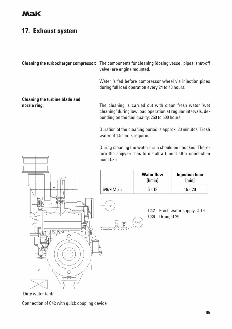
Cleaning the turbocharger compressor: The components for cleaning (dosing vessel, pipes, shut-offvalve) are engine mounted.
Water is fed before compressor wheel via injection pipesduring full load operation every 24 to 48 hours.
Cleaning the turbine blade andnozzle ring: The cleaning is carried out with clean fresh water "wet
cleaning" during low load operation at regular intervals, de-pending on the fuel quality, 250 to 500 hours.
Duration of the cleaning period is approx. 20 minutes. Freshwater of 1.5 bar is required.
During cleaning the water drain should be checked. There-fore the shipyard has to install a funnel after connectionpoint C36.
Water flow [l/min]
Injection time [min]
6/8/9 M 25 6 - 18 15 - 20
C42 Fresh water supply, Ø 16C36 Drain, Ø 25
Connection of C42 with quick coupling device
Dirty water tank
m
66
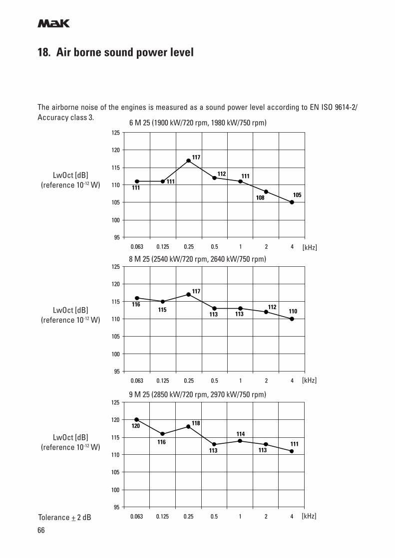
18. Air borne sound power level
The airborne noise of the engines is measured as a sound power level according to EN ISO 9614-2/Accuracy class 3.
Tolerance + 2 dB
LwOct [dB](reference 10-12 W)
LwOct [dB](reference 10-12 W)
LwOct [dB](reference 10-12 W)
6 M 25 (1900 kW/720 rpm, 1980 kW/750 rpm)
9 M 25 (2850 kW/720 rpm, 2970 kW/750 rpm)
8 M 25 (2540 kW/720 rpm, 2640 kW/750 rpm)
111
105108
111112
117
111
95
100
105
110
115
120
125
0.063 0.125 0.25 0.5 1 2 4 [kHz]
115 110112
113113
117
116
95
100
105
110
115
120
125
0.063 0.125 0.25 0.5 1 2 4 [kHz]
116 111113
114
113
118120
95
100
105
110
115
120
125
0.063 0.125 0.25 0.5 1 2 4 [kHz]
m
67
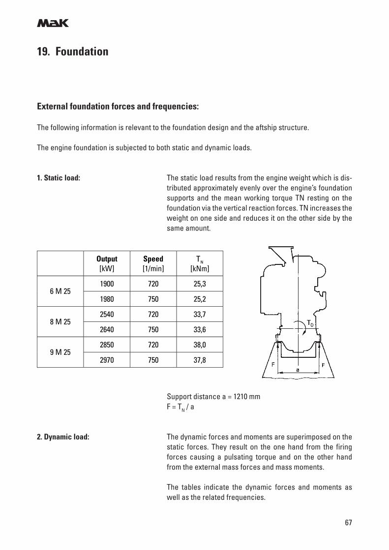
19. Foundation
Support distance a = 1210 mmF = TN / a
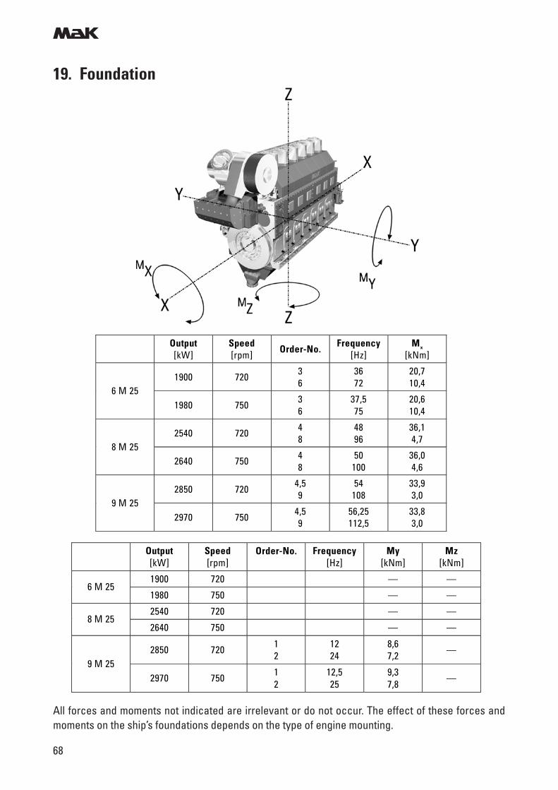
2. Dynamic load: The dynamic forces and moments are superimposed on thestatic forces. They result on the one hand from the firingforces causing a pulsating torque and on the other handfrom the external mass forces and mass moments.
The tables indicate the dynamic forces and moments aswell as the related frequencies.
External foundation forces and frequencies:
The following information is relevant to the foundation design and the aftship structure.
The engine foundation is subjected to both static and dynamic loads.
1. Static load: The static load results from the engine weight which is dis-tributed approximately evenly over the engine’s foundationsupports and the mean working torque TN resting on thefoundation via the vertical reaction forces. TN increases theweight on one side and reduces it on the other side by thesame amount.
Output [kW]
Speed [1/min]
TN [kNm]
1900 720 25,3 6 M 25
1980 750 25,2
2540 720 33,7 8 M 25
2640 750 33,6
2850 720 38,0 9 M 25
2970 750 37,8
m
68
All forces and moments not indicated are irrelevant or do not occur. The effect of these forces andmoments on the ship’s foundations depends on the type of engine mounting.
Output [kW]
Speed [rpm]
Order-No.
Frequency [Hz]
My [kNm]
Mz [kNm]
1900 720 — — 6 M 25
1980 750 — —
2540 720 — — 8 M 25
2640 750 — —
2850 720 1 2
12 24
8,6 7,2 —
9 M 25 2970 750 1
2 12,5 25
9,3 7,8
—
19. Foundation
Output [kW]
Speed [rpm] Order-No.
Frequency [Hz]
Mx [kNm]
1900 720 3 6
36 72
20,7 10,4
6 M 25 1980 750 3
6 37,5 75
20,6 10,4
2540 720 4 8
48 96
36,1 4,7
8 M 25 2640 750 4
8 50
100 36,0 4,6
2850 720 4,5 9
54 108
33,9 3,0
9 M 25 2970 750 4,5
9 56,25 112,5
33,8 3,0
m
69
19. Foundation
2.1 Rigid mounting: The vertical reaction forces resulting from the torque varia-tion Mx are the most important disturbances to which theengine foundation is subjected. As regards dynamic load,the indicated moments Mx only represent the exciting val-ues and can only be compared among each other. The ac-tual forces to which the foundation is subjected depend onthe mounting arrangement and the rigidity of the foundationitself.
In order to make sure that there are no local resonant vibra-tions in the ship’s structure, the natural frequencies of im-portant components and partial structures must be suffi-ciently far away (+ 30%) from the indicated main excitingfrequencies.
2.2 Resilient mounting: The dynamic foundation forces can be considerably re-duced by means of resilient engine mounting.
General note: The shipyard is solely responsible for the adequate designand quality of the foundation.
Information on foundation bolts (required pretightening tor-ques, elongation, yield point), steel chocks, side stoppersand alignment bolts is to be gathered from the foundationplans.
Examples "for information only" for the design of the screwconnections will be made available as required.
If pourable resin is used it is recommendable to employ au-thorized workshops of resin manufacturers approved by theclassification societies for design and execution.
It has to be taken into account that the permissible surfacepressure for resin is lower than for steel chocks and there-fore the tightening torques for the bolts are reduced corre-spondingly.
m
70
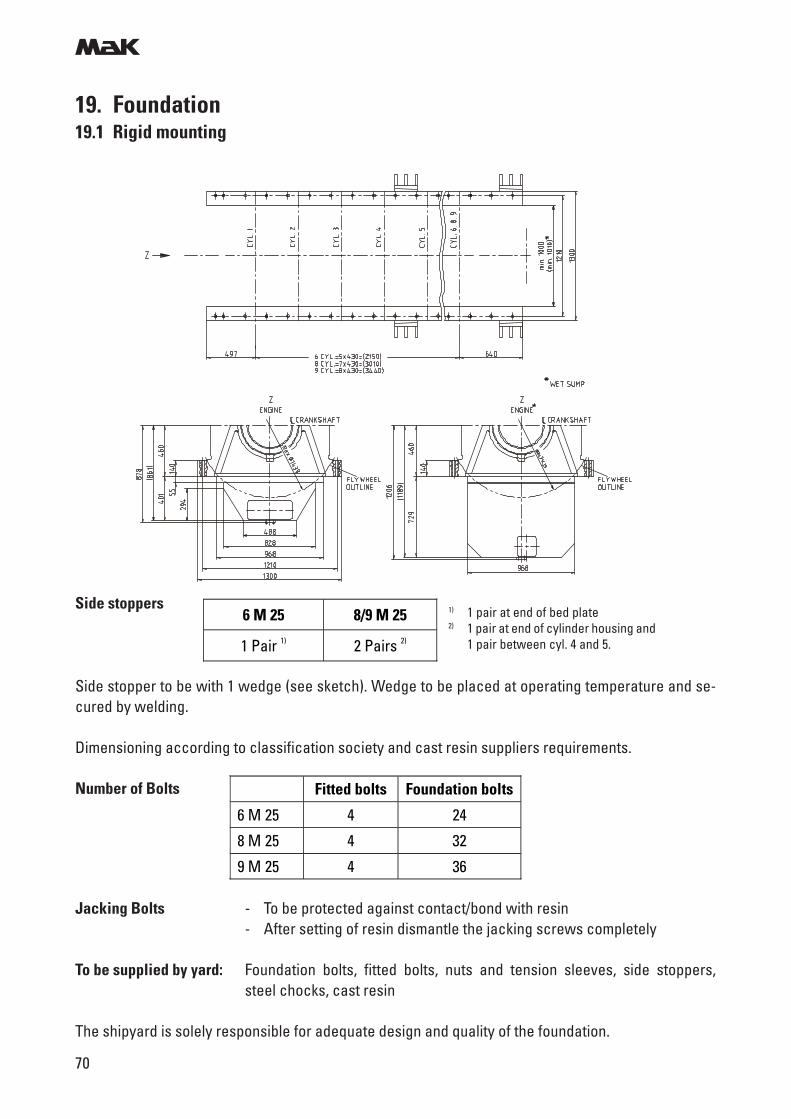
19. Foundation19.1 Rigid mounting
Side stopper to be with 1 wedge (see sketch). Wedge to be placed at operating temperature and se-cured by welding.
Dimensioning according to classification society and cast resin suppliers requirements.
Number of Bolts
Jacking Bolts - To be protected against contact/bond with resin- After setting of resin dismantle the jacking screws completely
To be supplied by yard: Foundation bolts, fitted bolts, nuts and tension sleeves, side stoppers,steel chocks, cast resin
The shipyard is solely responsible for adequate design and quality of the foundation.
Fitted bolts Foundation bolts
6 M 25 4 24
8 M 25 4 32
9 M 25 4 36
6 M 25 8/9 M 25
1 Pair 1) 2 Pairs 2)
Side stoppers 1) 1 pair at end of bed plate2) 1 pair at end of cylinder housing and
1 pair between cyl. 4 and 5.
m
71
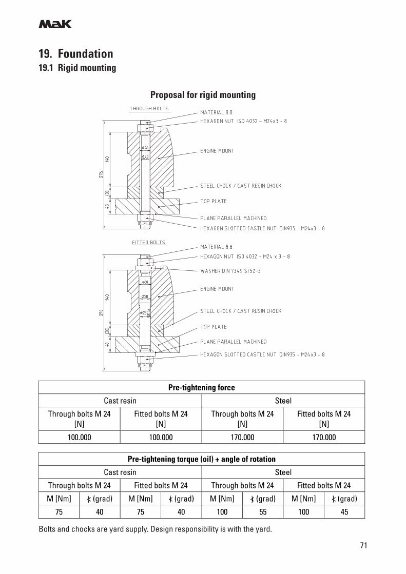
19. Foundation19.1 Rigid mounting
Proposal for rigid mounting
Bolts and chocks are yard supply. Design responsibility is with the yard.
Pre-tightening force
Cast resin Steel
Through bolts M 24 [N]
Fitted bolts M 24 [N]
Through bolts M 24 [N]
Fitted bolts M 24 [N]
100.000 100.000 170.000 170.000
Pre-tightening torque (oil) + angle of rotation
Cast resin Steel
Through bolts M 24 Fitted bolts M 24 Through bolts M 24 Fitted bolts M 24
M [Nm] < (grad) M [Nm] < (grad) M [Nm] < (grad) M [Nm] < (grad)
75 40 75 40 100 55 100 45
) ) ) )
m
72
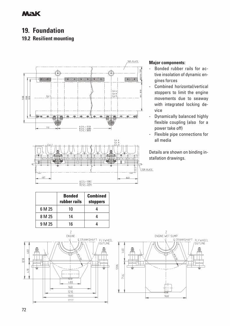
19. Foundation19.2 Resilient mounting
Major components:- Bonded rubber rails for ac-
tive insolation of dynamic en-gines forces
- Combined horizontal/verticalstoppers to limit the enginemovements due to seawaywith integrated locking de-vice
- Dynamically balanced highlyflexible coupling (also for apower take off)
- Flexible pipe connections forall media
Details are shown on binding in-stallation drawings.
Bonded
rubber rails Combined stoppers
6 M 25 10 4
8 M 25 14 4
9 M 25 16 4
m
73
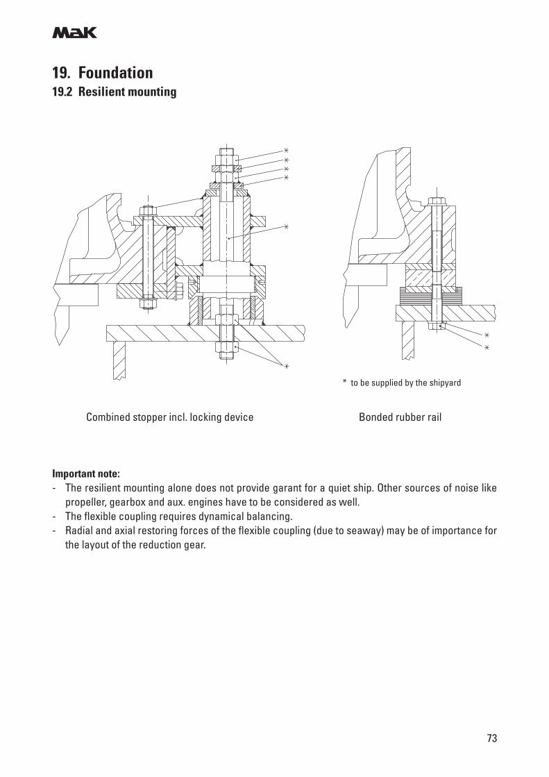
Important note:- The resilient mounting alone does not provide garant for a quiet ship. Other sources of noise like
propeller, gearbox and aux. engines have to be considered as well.- The flexible coupling requires dynamical balancing.- Radial and axial restoring forces of the flexible coupling (due to seaway) may be of importance for
the layout of the reduction gear.
* to be supplied by the shipyard
Combined stopper incl. locking device Bonded rubber rail
19. Foundation19.2 Resilient mounting
m
74
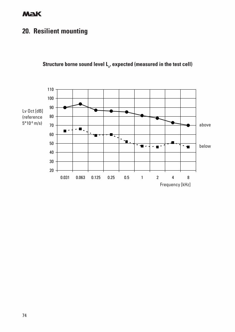
20. Resilient mounting
Structure borne sound level Lv, expected (measured in the test cell)
Lv Oct [dB](reference5*10-8 m/s)
20
30
40
50
60
70
80
90
100
110
0.031 0.063 0.125 0.25 0.5 1 2 4 8
Frequency [kHz]
above
below
m
75
21. Power transmission
Coupling between engine and gearbox
For all types of plants the engines will be equipped with flexible flange couplings.
The guards for the flexible couplings should be of perforated plate or gratings to ensure an optimumheat dissipation (yard supply).
Mass moments of inertia
* Running gear with balance weights and vibration damper
Selection of flexible couplings
The calculation of the coupling torque for main couplings is carried out acc. to the following formula.
T KN [kNm] > · · 9,55Po [kW]no [min-1]
Po Engine outputno Engine speedTKN Nominal torque of the coupling in the catalog
For installations with a gearbox PTO it is recommended to oversize the PTO coupling by the factor 2in order to have sufficient safety margin in the event of misfiring.
Speed [rpm]
Engine * [kgm2]
Flywheel [kgm2]
Total [kgm2]
6 M 25 135 355
8 M 25 205 425
9 M 25
720/750
215
220
435
m
76
21. Power transmission
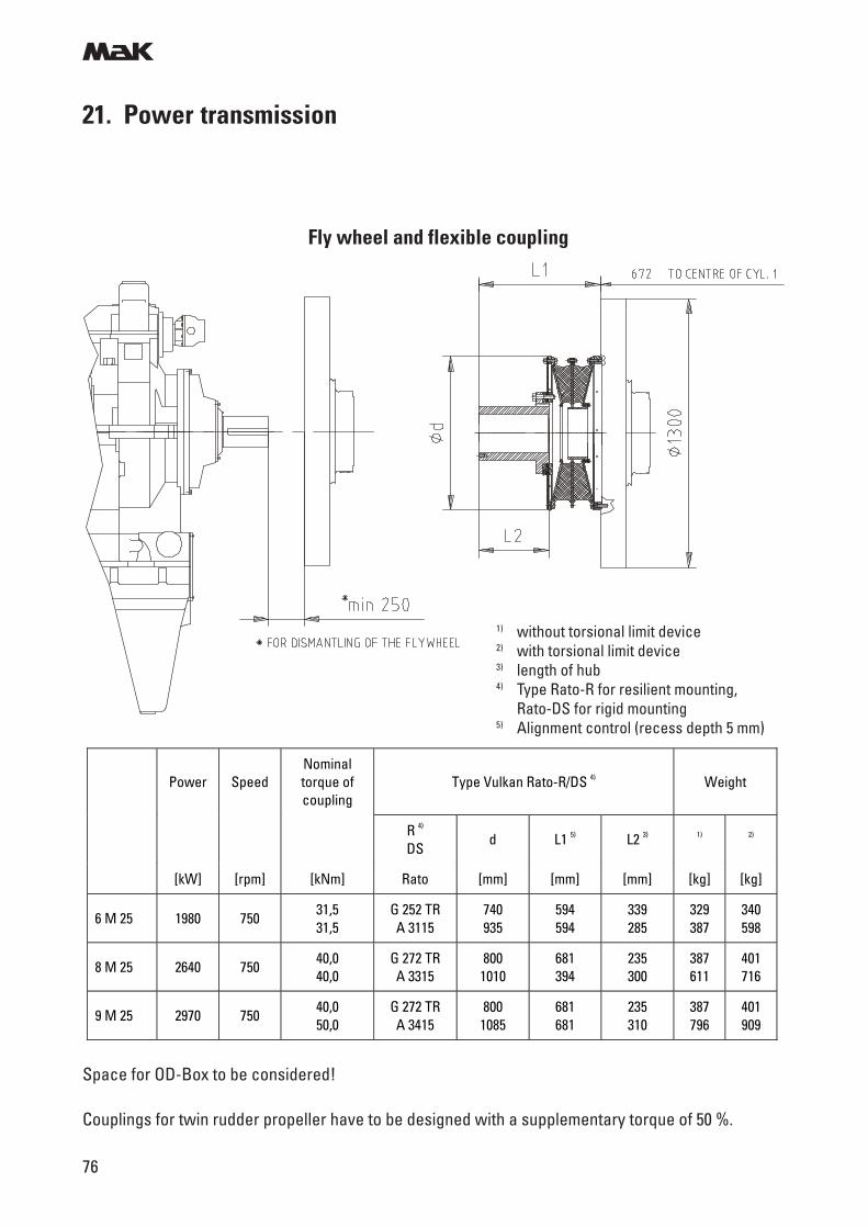
Fly wheel and flexible coupling
Space for OD-Box to be considered!
Couplings for twin rudder propeller have to be designed with a supplementary torque of 50 %.
Power Speed Nominal torque of coupling
Type Vulkan Rato-R/DS 4) Weight
R 4) DS
d L1 5) L2 3) 1) 2)
[kW] [rpm] [kNm] Rato [mm] [mm] [mm] [kg] [kg]
6 M 25 1980 750 31,5 31,5
G 252 TR A 3115
740 935
594 594
339 285
329 387
340 598
8 M 25 2640 750 40,0 40,0
G 272 TR A 3315
800 1010
681 394
235 300
387 611
401 716
9 M 25 2970 750 40,0 50,0
G 272 TR A 3415
800 1085
681 681
235 310
387 796
401 909
1) without torsional limit device2) with torsional limit device3) length of hub4) Type Rato-R for resilient mounting,
Rato-DS for rigid mounting5) Alignment control (recess depth 5 mm)
m
77
21. Power transmission
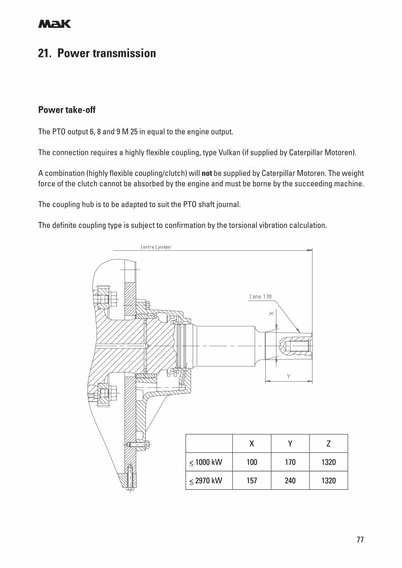
Power take-off
The PTO output 6, 8 and 9 M 25 in equal to the engine output.
The connection requires a highly flexible coupling, type Vulkan (if supplied by Caterpillar Motoren).
A combination (highly flexible coupling/clutch) will not be supplied by Caterpillar Motoren. The weightforce of the clutch cannot be absorbed by the engine and must be borne by the succeeding machine.
The coupling hub is to be adapted to suit the PTO shaft journal.
The definite coupling type is subject to confirmation by the torsional vibration calculation.
X Y Z
< 1000 kW 100 170 1320
< 2970 kW 157 240 1320
m
78
21. Power transmission
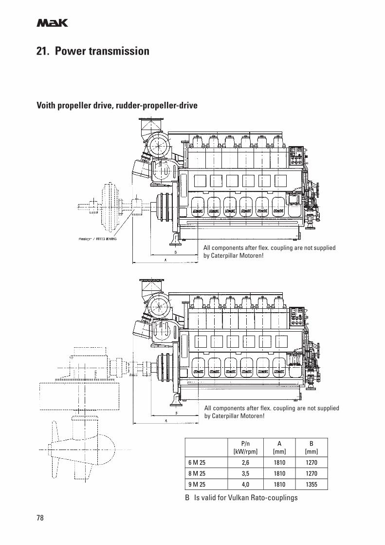
Voith propeller drive, rudder-propeller-drive
All components after flex. coupling are not suppliedby Caterpillar Motoren!
All components after flex. coupling are not suppliedby Caterpillar Motoren!
B Is valid for Vulkan Rato-couplings
P/n [kW/rpm]
A [mm]
B [mm]
6 M 25 2,6 1810 1270
8 M 25 3,5 1810 1270
9 M 25 4,0 1810 1355
m
79
22. Data for torsional vibration calculation
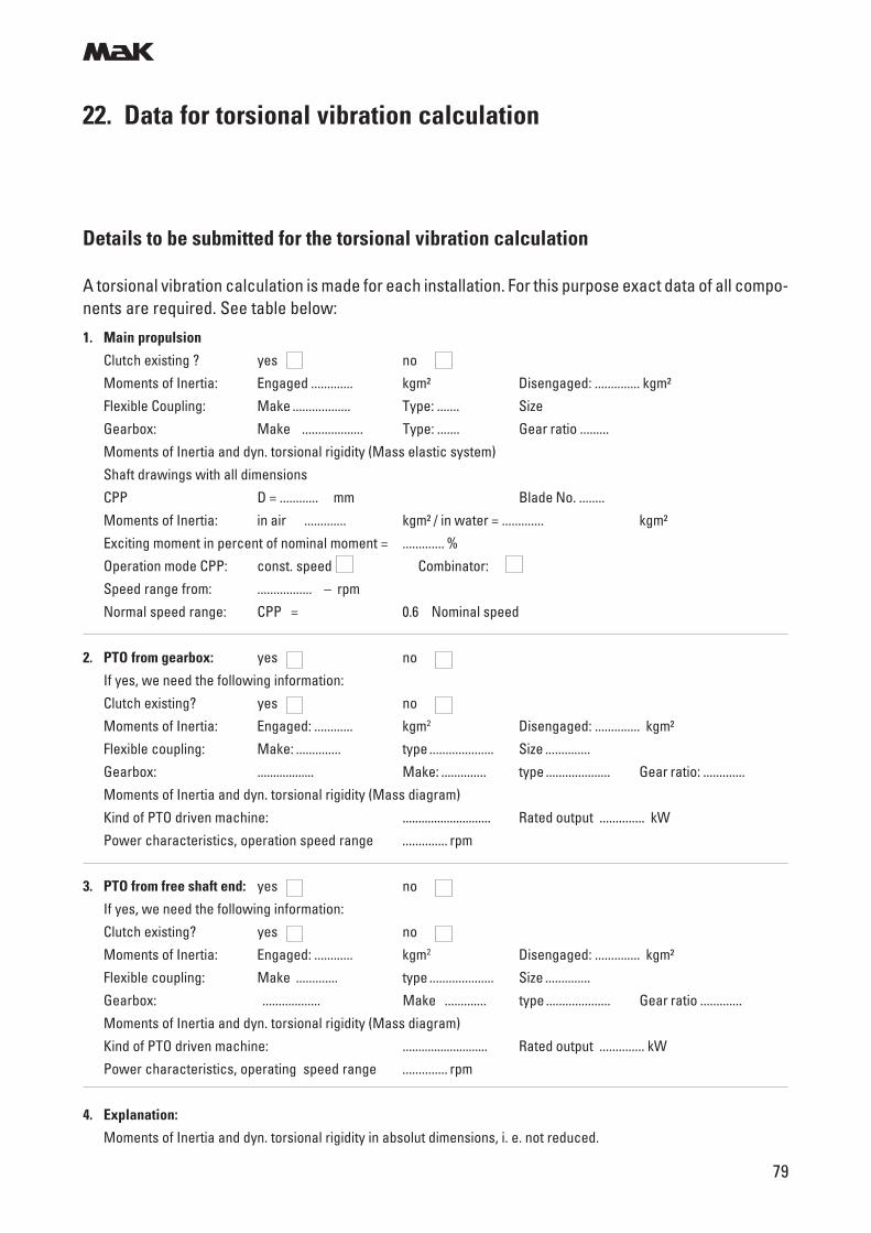
Details to be submitted for the torsional vibration calculation
A torsional vibration calculation is made for each installation. For this purpose exact data of all compo-nents are required. See table below:
1. Main propulsion
Clutch existing ? yes no
Moments of Inertia: Engaged ............. kgm² Disengaged: .............. kgm²
Flexible Coupling: Make .................. Type: ....... Size
Gearbox: Make ................... Type: ....... Gear ratio .........
Moments of Inertia and dyn. torsional rigidity (Mass elastic system)
Shaft drawings with all dimensions
CPP D = ............ mm Blade No. ........
Moments of Inertia: in air ............. kgm² / in water = ............. kgm²
Exciting moment in percent of nominal moment = ............. %
Operation mode CPP: const. speed Combinator:
Speed range from: ................. – rpm
Normal speed range: CPP = 0.6 Nominal speed
2. PTO from gearbox: yes no
If yes, we need the following information:
Clutch existing? yes no
Moments of Inertia: Engaged: ............ kgm2 Disengaged: .............. kgm²
Flexible coupling: Make: .............. type .................... Size ..............
Gearbox: .................. Make: .............. type .................... Gear ratio: .............
Moments of Inertia and dyn. torsional rigidity (Mass diagram)
Kind of PTO driven machine: ............................ Rated output .............. kW
Power characteristics, operation speed range .............. rpm
3. PTO from free shaft end: yes no
If yes, we need the following information:
Clutch existing? yes no
Moments of Inertia: Engaged: ............ kgm2 Disengaged: .............. kgm²
Flexible coupling: Make ............. type .................... Size ..............
Gearbox: .................. Make ............. type .................... Gear ratio .............
Moments of Inertia and dyn. torsional rigidity (Mass diagram)
Kind of PTO driven machine: ........................... Rated output .............. kW
Power characteristics, operating speed range .............. rpm
4. Explanation:
Moments of Inertia and dyn. torsional rigidity in absolut dimensions, i. e. not reduced.
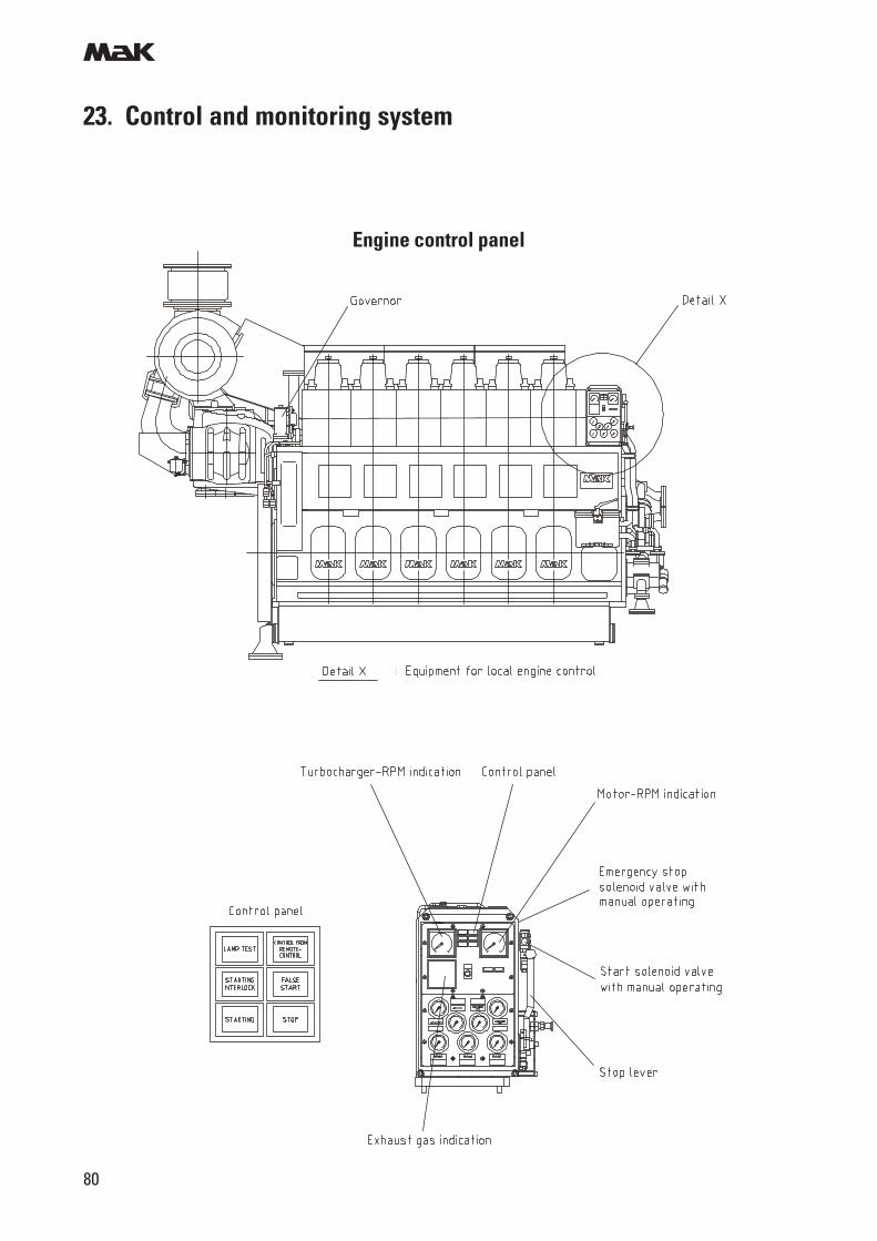
m
80
23. Control and monitoring system
Engine control panel
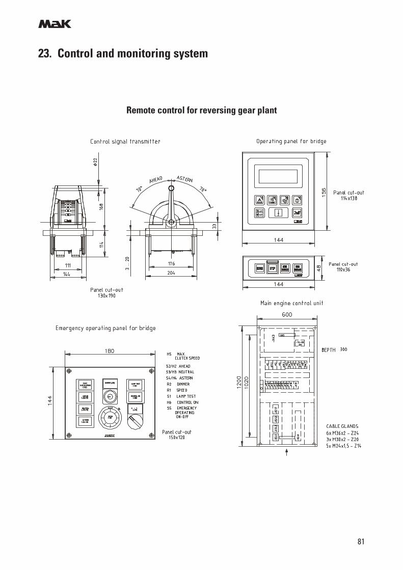
m
81
23. Control and monitoring system
Remote control for reversing gear plant
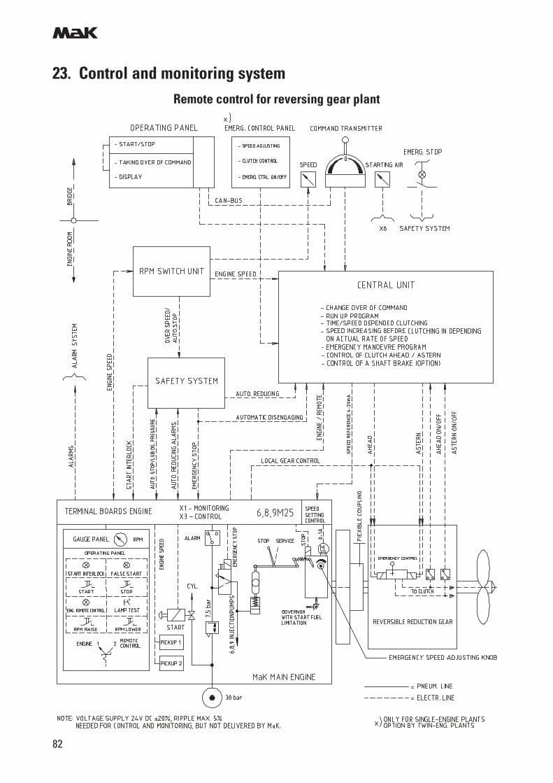
m
82
23. Control and monitoring systemRemote control for reversing gear plant
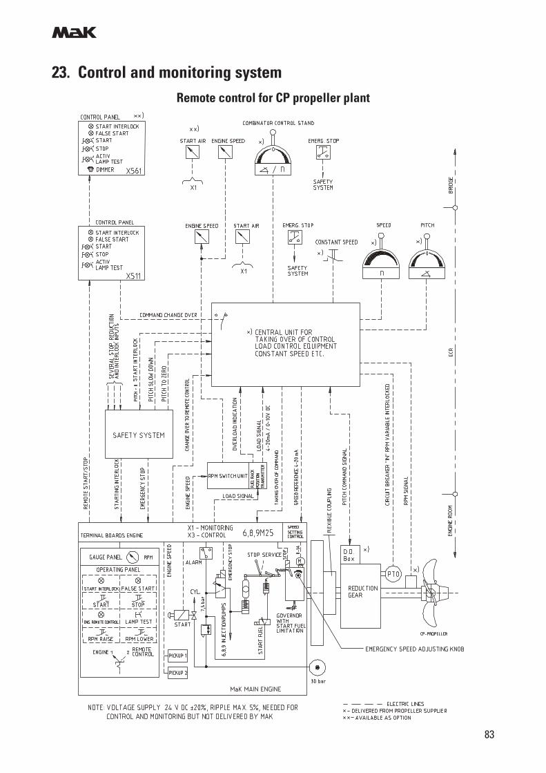
m
83
23. Control and monitoring systemRemote control for CP propeller plant
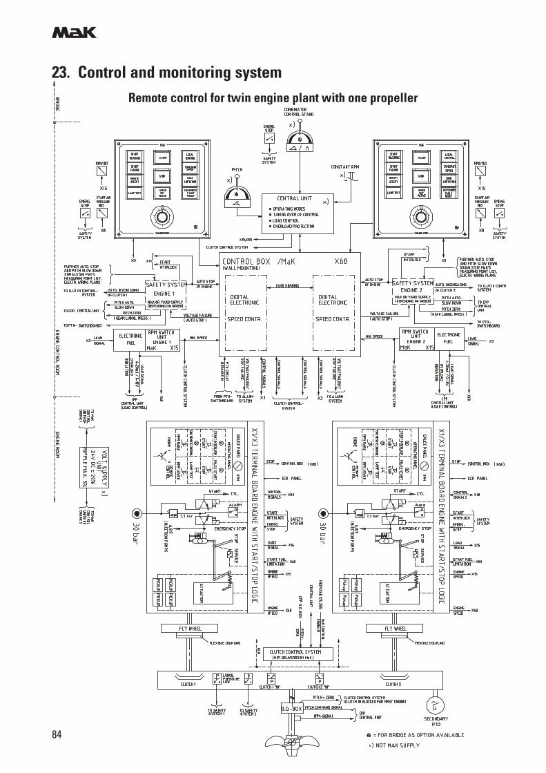
m
84
23. Control and monitoring systemRemote control for twin engine plant with one propeller
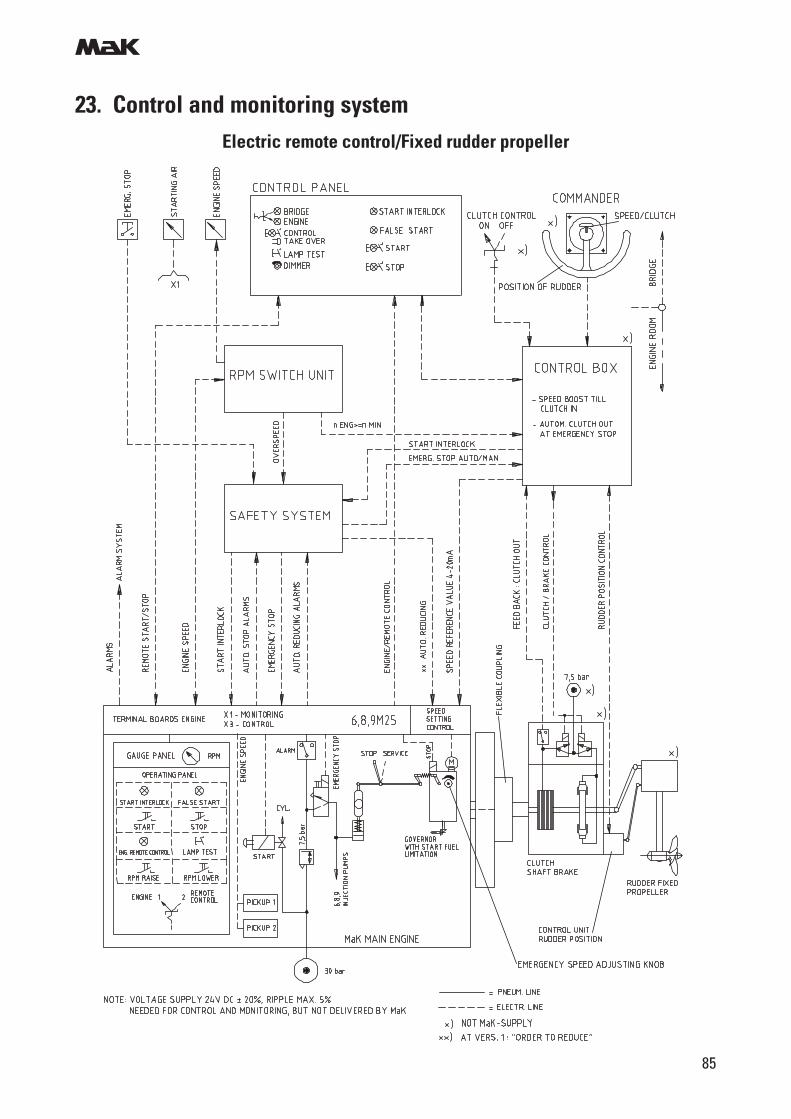
m
85
23. Control and monitoring systemElectric remote control/Fixed rudder propeller
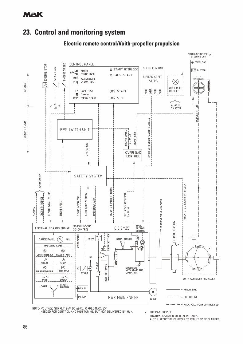
m
86
23. Control and monitoring systemElectric remote control/Voith-propeller propulsion
m
87
23. Control and monitoring system
Speed control
Main engines are equipped with a mech./hydr. speed governor (Milli Ampere Speed setting). With thefollowing equipment:
- Stepper motor in the top part of the governor for remote speed control- Separate stepper motor control with adjustable speed range and speed ramp. Voltage supply =
24 V DC
The control is fitted easily accessible on the engine in the terminal board box (X3) especially providedfor control components.
The set speed value of
nmin = 4 mAnmax = 20 mA
is converted into a current required by the stepper motor.
- Speed setting knob (emergency speed setting)- Shut-down solenoid (24 V DC/100 % duty cycle) for remote stop (not for automatic engine stop).- Steplessly adjustable droop on the governor from 0 - 10 %- Standard setting: 0 %- Device for optimization of the governor characteristic- Serrated drive shaft (for easy service)
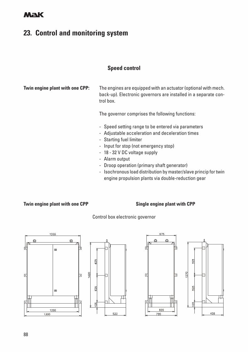
m
88
23. Control and monitoring system
Speed control
Twin engine plant with one CPP: The engines are equipped with an actuator (optional with mech.back-up). Electronic governors are installed in a separate con-trol box.
The governor comprises the following functions:
- Speed setting range to be entered via parameters- Adjustable acceleration and deceleration times- Starting fuel limiter- Input for stop (not emergency stop)- 18 - 32 V DC voltage supply- Alarm output- Droop operation (primary shaft generator)- Isochronous load distribution by master/slave princip for twin
engine propulsion plants via double-reduction gear
Twin engine plant with one CPP Single engine plant with CPP
Control box electronic governor
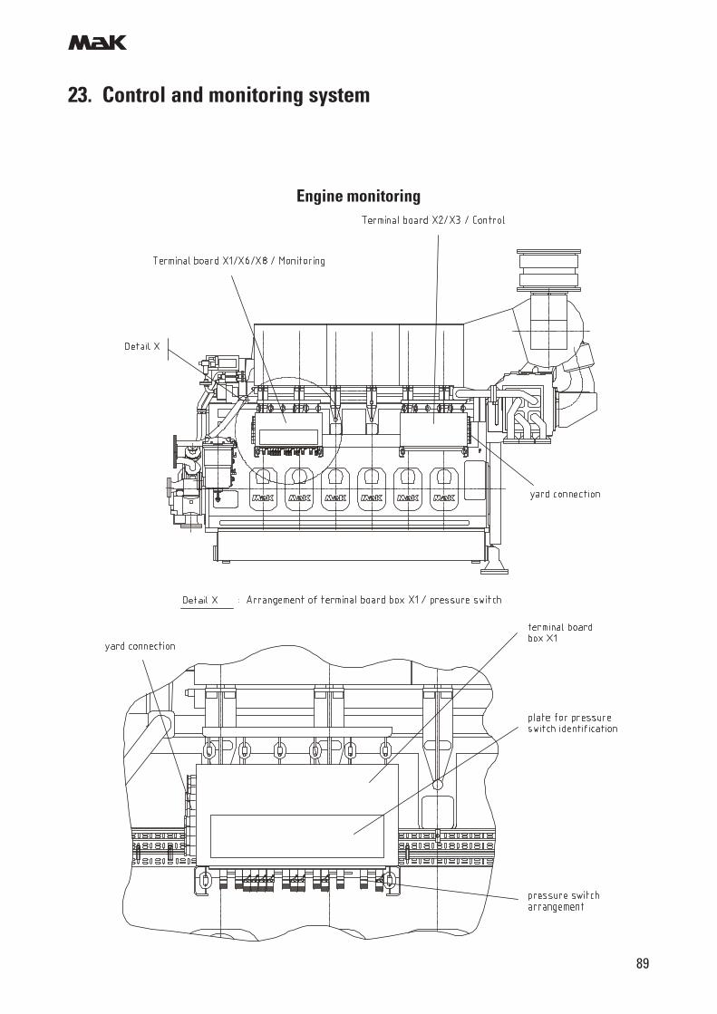
m
89
23. Control and monitoring system
Engine monitoring
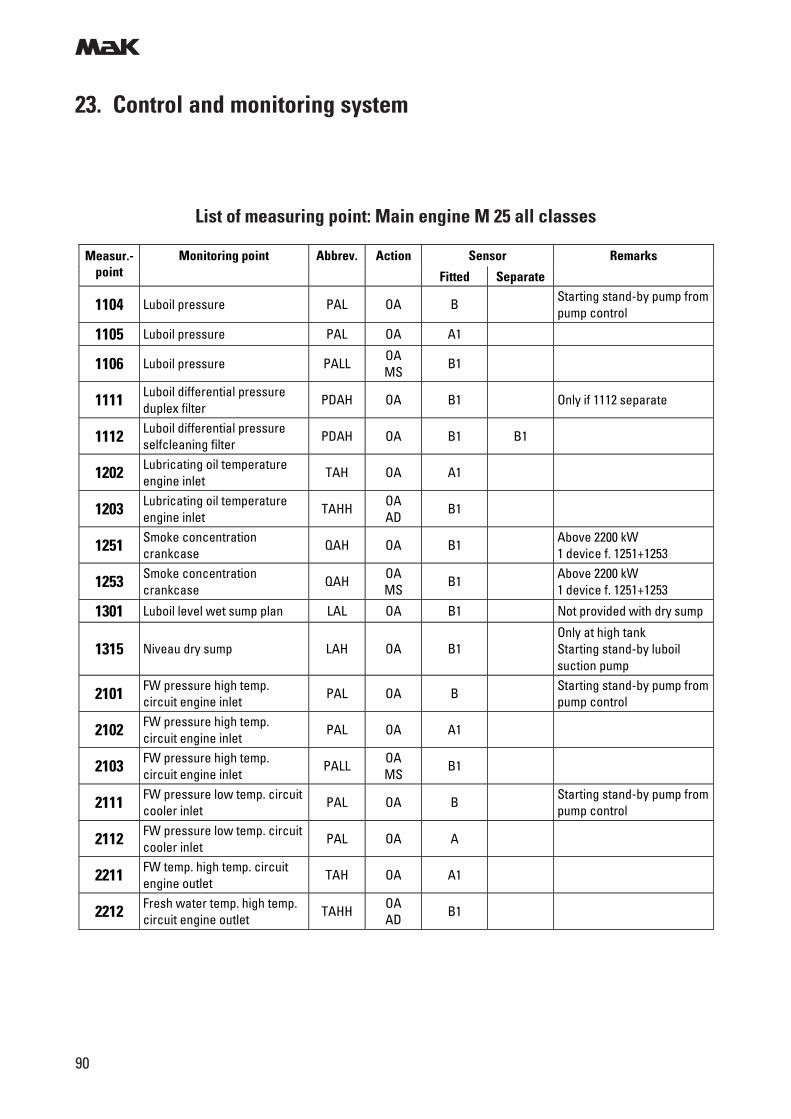
m
90
23. Control and monitoring system
List of measuring point: Main engine M 25 all classes
Sensor Measur.-point
Monitoring point Abbrev. Action
Fitted Separate
Remarks
1104 Luboil pressure PAL OA B Starting stand-by pump from pump control
1105 Luboil pressure PAL OA A1
1106 Luboil pressure PALL OA MS
B1
1111 Luboil differential pressure duplex filter
PDAH OA B1 Only if 1112 separate
1112 Luboil differential pressure selfcleaning filter
PDAH OA B1 B1
1202 Lubricating oil temperature engine inlet
TAH OA A1
1203 Lubricating oil temperature engine inlet
TAHH OA AD
B1
1251 Smoke concentration crankcase
QAH OA B1 Above 2200 kW 1 device f. 1251+1253
1253 Smoke concentration crankcase
QAH OA MS
B1 Above 2200 kW 1 device f. 1251+1253
1301 Luboil level wet sump plan LAL OA B1 Not provided with dry sump
1315 Niveau dry sump LAH OA B1 Only at high tank Starting stand-by luboil suction pump
2101 FW pressure high temp. circuit engine inlet
PAL OA B Starting stand-by pump from pump control
2102 FW pressure high temp. circuit engine inlet
PAL OA A1
2103 FW pressure high temp. circuit engine inlet
PALL OA MS
B1
2111 FW pressure low temp. circuit cooler inlet
PAL OA B Starting stand-by pump from pump control
2112 FW pressure low temp. circuit cooler inlet
PAL OA A
2211 FW temp. high temp. circuit engine outlet
TAH OA A1
2212 Fresh water temp. high temp. circuit engine outlet
TAHH OA AD
B1
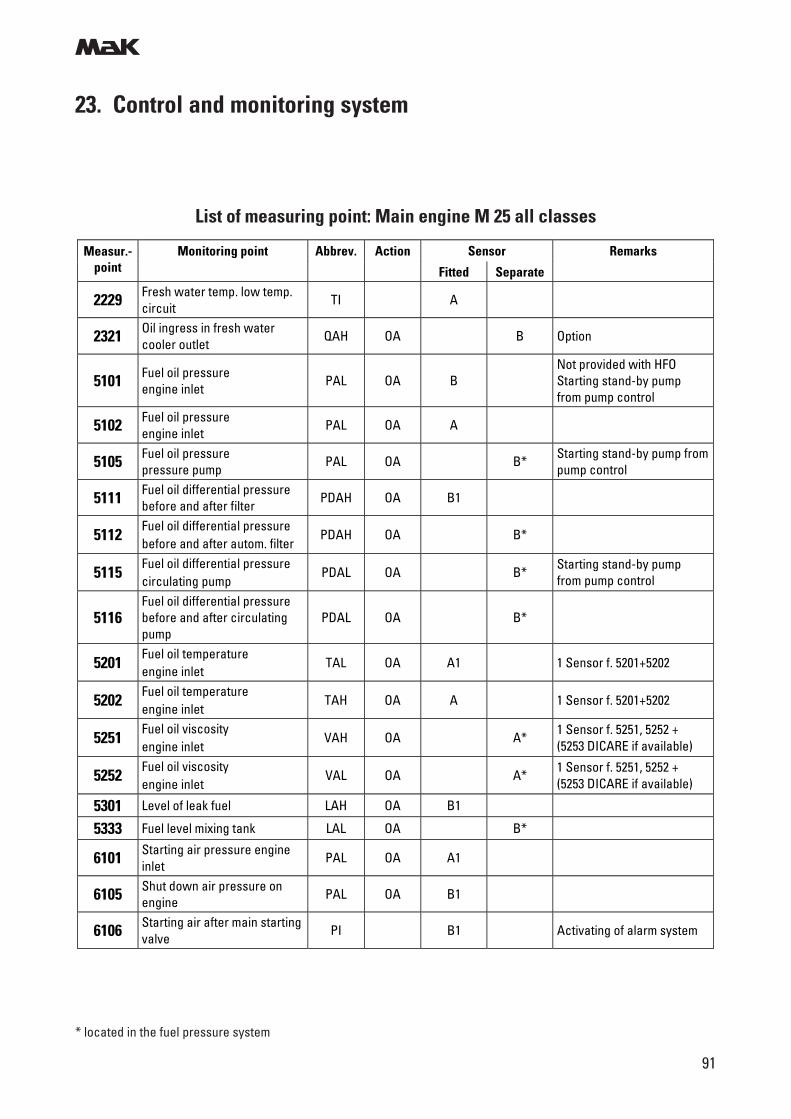
m
91
23. Control and monitoring system
List of measuring point: Main engine M 25 all classes
* located in the fuel pressure system
Sensor Measur.-point
Monitoring point Abbrev. Action
Fitted Separate
Remarks
2229 Fresh water temp. low temp. circuit
TI A
2321 Oil ingress in fresh water cooler outlet
QAH OA B Option
5101 Fuel oil pressure engine inlet
PAL OA B Not provided with HFO Starting stand-by pump from pump control
5102 Fuel oil pressure engine inlet
PAL OA A
5105 Fuel oil pressure pressure pump
PAL OA B* Starting stand-by pump from pump control
5111 Fuel oil differential pressure before and after filter
PDAH OA B1
5112 Fuel oil differential pressure before and after autom. filter
PDAH OA B*
5115 Fuel oil differential pressure circulating pump
PDAL OA B* Starting stand-by pump from pump control
5116 Fuel oil differential pressure before and after circulating pump
PDAL OA B*
5201 Fuel oil temperature engine inlet
TAL OA A1 1 Sensor f. 5201+5202
5202 Fuel oil temperature engine inlet
TAH OA A 1 Sensor f. 5201+5202
5251 Fuel oil viscosity engine inlet
VAH OA A* 1 Sensor f. 5251, 5252 + (5253 DICARE if available)
5252 Fuel oil viscosity engine inlet
VAL OA A* 1 Sensor f. 5251, 5252 + (5253 DICARE if available)
5301 Level of leak fuel LAH OA B1
5333 Fuel level mixing tank LAL OA B*
6101 Starting air pressure engine inlet
PAL OA A1
6105 Shut down air pressure on engine
PAL OA B1
6106 Starting air after main starting valve
PI B1 Activating of alarm system
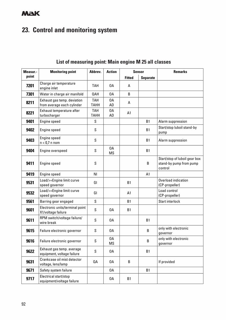
m
92
23. Control and monitoring system
List of measuring point: Main engine M 25 all classes
Sensor Measur.-point
Monitoring point Abbrev. Action
Fitted Separate
Remarks
7201 Charge air temperature engine inlet
TAH OA A
7301 Water in charge air manifold QAH OA B
8211 Exhaust gas temp. deviation from average each cylinder
TAH TAHH
OA AD
A
8221 Exhaust temperature after turbocharger
TAH TAHH
OA AD
A1
9401 Engine speed S B1 Alarm suppression
9402 Engine speed S B1 Start/stop luboil stand-by pump
9403 Engine speed n < 0,7 n nom
S B1 Alarm suppression
9404 Engine overspeed S OA MS
B1
9411 Engine speed S B Start/stop of luboil gear box stand-by pump from pump control
9419 Engine speed NI A1
9531 Load/>=Engine limit curve speed governor
GI B1 Overload indication (CP-propeller)
9532 Load/>=Engine limit curve speed governor
GI A1 Load control (CP-propeller)
9561 Barring gear engaged S B1 Start interlock
9601 Electronic units/terminal point X1/voltage failure
S OA B1
9611 RPM switch/voltage failure/ wire break
S OA B1
9615 Failure electronic governor S OA B only with electronic governor
9616 Failure electronic governor S OA MS
B only with electronic governor
9622 Exhaust gas temp. average equipment, voltage failure
S OA B1
9631 Crankcase oil mist detector voltage, lens/lamp
QA OA B If provided
9671 Safety system failure OA B1
9717 Electrical start/stop equipment/voltage failure
OA B1
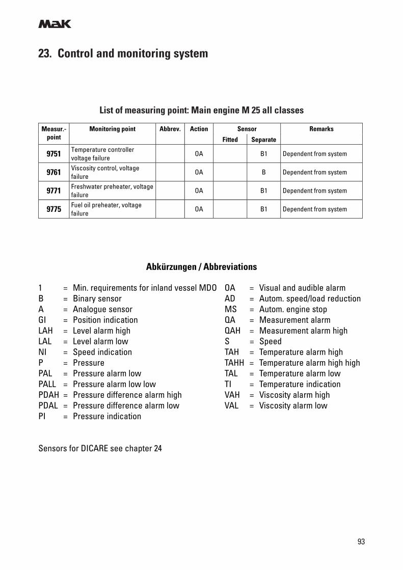
m
93
23. Control and monitoring system
List of measuring point: Main engine M 25 all classes
Sensor Measur.-point
Monitoring point Abbrev. Action
Fitted Separate
Remarks
9751 Temperature controller voltage failure
OA B1 Dependent from system
9761 Viscosity control, voltage failure
OA B Dependent from system
9771 Freshwater preheater, voltage failure
OA B1 Dependent from system
9775 Fuel oil preheater, voltage failure
OA B1 Dependent from system
Abkürzungen / Abbreviations
1 = Min. requirements for inland vessel MDO OA = Visual and audible alarmB = Binary sensor AD = Autom. speed/load reductionA = Analogue sensor MS = Autom. engine stopGI = Position indication QA = Measurement alarmLAH = Level alarm high QAH = Measurement alarm highLAL = Level alarm low S = SpeedNI = Speed indication TAH = Temperature alarm highP = Pressure TAHH = Temperature alarm high highPAL = Pressure alarm low TAL = Temperature alarm lowPALL = Pressure alarm low low TI = Temperature indicationPDAH = Pressure difference alarm high VAH = Viscosity alarm highPDAL = Pressure difference alarm low VAL = Viscosity alarm lowPI = Pressure indication
Sensors for DICARE see chapter 24
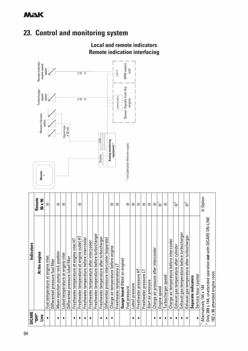
m
94
23. Control and monitoring system
Local and remote indicatorsRemote indication interfacing
* no
t Cat
erpi
llar M
otor
en s
uppl
y
mA
VΩ
mV
mA
V
Sens
or S
igna
ls fr
om th
een
gine
RPM
sw
itch
unit
Anal
og-m
onito
ring
equi
pmen
t *
Disp
lay
(mA)
Rem
ote
indi
cato
rop
tion
Turb
ocha
rger
spee
dop
tion
Rem
ote
indi
cato
ren
gine
spe
edop
tion
Mon
itor
*
Sign
al ty
pe4-
20 m
A
0 - 10 V
0 - 10 V
Indi
cato
rs
DIC
ARE
"O
FF"
Line
A
t the
eng
ine
Rem
ote
96 x
96
• Fu
el te
mpe
ratu
re a
t eng
ine
inle
t ⊗
Diffe
rent
ial p
ress
ure
fuel
filte
r
• M
ean
inje
ctio
n pu
mp
rack
pos
ition
⊗
•
Lubo
il te
mpe
ratu
re a
t eng
ine
inle
t ⊗
Diffe
rent
ial p
ress
ure
lubo
il fil
ter
•
Fres
hwat
er te
mpe
ratu
re a
t eng
ine
inle
t HT
•
Fres
hwat
er te
mpe
ratu
re a
t eng
ine
outle
t HT
⊗
• Fr
eshw
ater
tem
pera
ture
bef
ore
inte
rcoo
ler
•
Fres
hwat
er te
mpe
ratu
re a
fter i
nter
cool
er
Fres
hwat
er te
mpe
ratu
re b
efor
e tu
rboc
harg
er
•
Fres
hwat
er te
mpe
ratu
re a
fter t
urbo
char
ger
•
Diffe
rent
ial p
ress
ure
inte
rcoo
ler (
sepa
rate
)
• Ch
arge
air
tem
pera
ture
bef
ore
engi
ne
⊗
Fr
eshw
ater
tem
pera
ture
LT
⊗
G
auge
boa
rd (f
itted
on
engi
ne)
Fuel
pre
ssur
e ⊗
• Lu
boil
pres
sure
⊗
•
Fres
hwat
er p
ress
ure
HT
⊗
Fr
eshw
ater
pre
ssur
e LT
⊗
Star
t air
pres
sure
⊗
•
Char
ge a
ir pr
essu
re a
fter i
nter
cool
er
⊗
• En
gine
spe
ed
⊗1)
• Tu
rboc
harg
er s
peed
⊗
•
Char
ge a
ir te
mpe
ratu
re b
efor
e in
terc
oole
r
• Ex
haus
t gas
tem
pera
ture
afte
r cyl
inde
r ⊗
2)
• Ex
haus
t gas
tem
pera
ture
bef
ore
turb
ocha
rger
• Ex
haus
t gas
tem
pera
ture
afte
r tur
boch
arge
r ⊗
2)
• Se
para
te in
dica
tors
Se
rvic
e ho
ur c
ount
er
1) A
ltern
ativ
ely
144
x 14
4 2) O
nly
288
x 14
4, u
natte
nded
ope
ratio
n no
t with
DIC
ARE
ON
-LIN
E
182
x 96
atte
nded
eng
ine
room
⊗ O
ptio
n
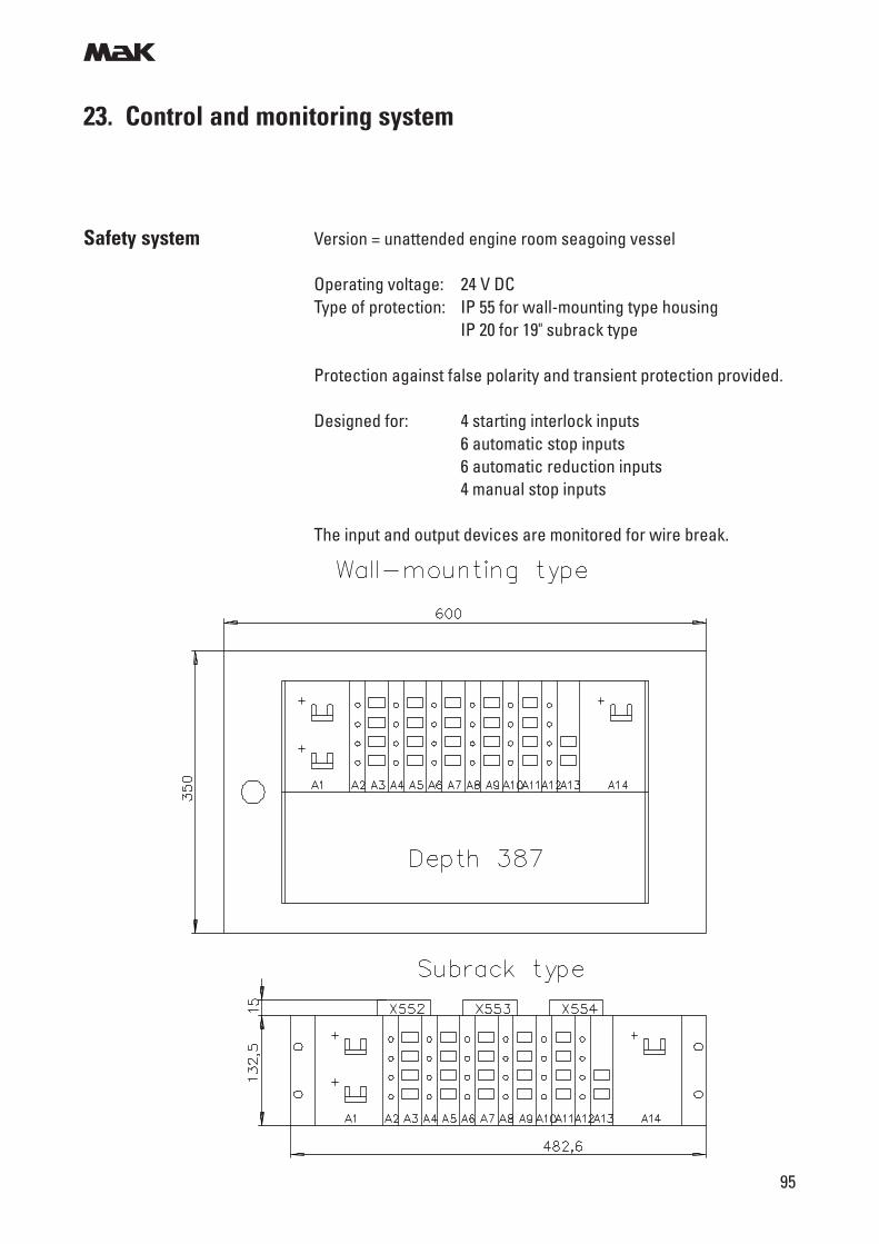
m
95
23. Control and monitoring system
Safety system Version = unattended engine room seagoing vessel
Operating voltage: 24 V DCType of protection: IP 55 for wall-mounting type housing
IP 20 for 19" subrack type
Protection against false polarity and transient protection provided.
Designed for: 4 starting interlock inputs6 automatic stop inputs6 automatic reduction inputs4 manual stop inputs
The input and output devices are monitored for wire break.
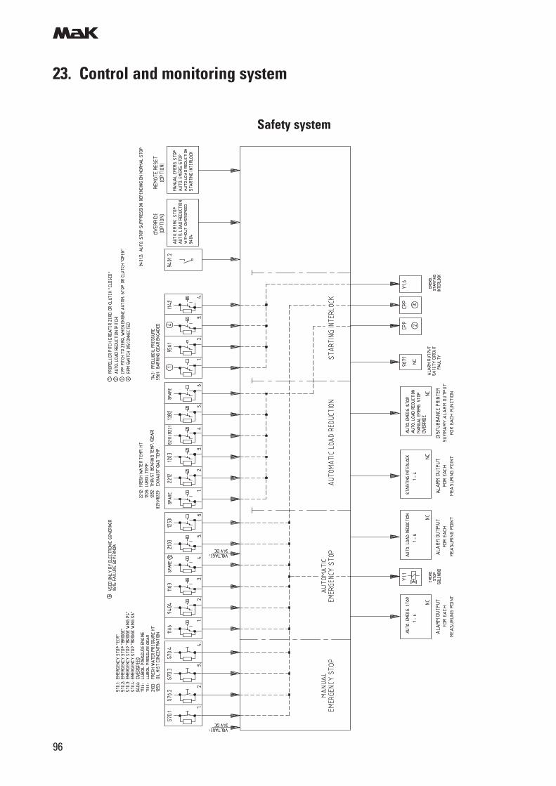
m
96
23. Control and monitoring system
Safety system
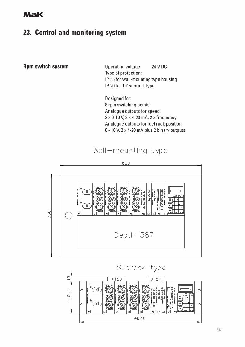
m
97
23. Control and monitoring system
Rpm switch system Operating voltage: 24 V DCType of protection:IP 55 for wall-mounting type housingIP 20 for 19" subrack type
Designed for:8 rpm switching pointsAnalogue outputs for speed:2 x 0-10 V, 2 x 4-20 mA, 2 x frequencyAnalogue outputs for fuel rack position:0 - 10 V, 2 x 4-20 mA plus 2 binary outputs
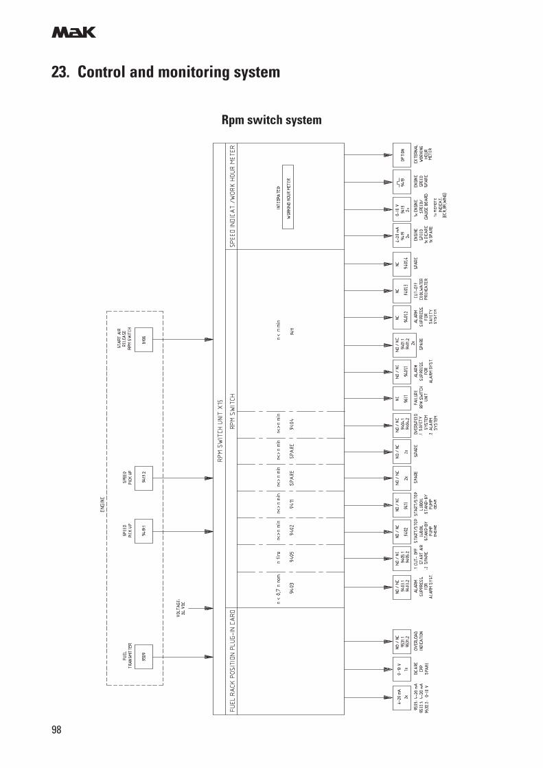
m
98
23. Control and monitoring system
Rpm switch system
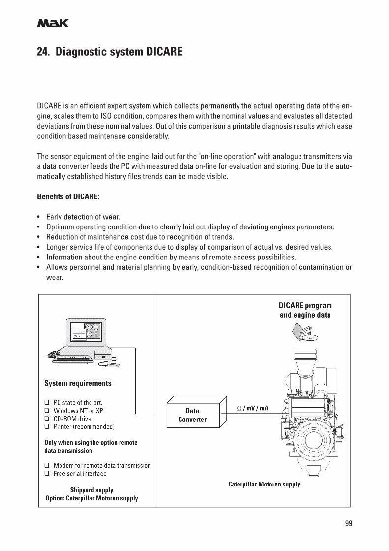
m
99
24. Diagnostic system DICARE
DICARE is an efficient expert system which collects permanently the actual operating data of the en-gine, scales them to ISO condition, compares them with the nominal values and evaluates all detecteddeviations from these nominal values. Out of this comparison a printable diagnosis results which easecondition based maintenace considerably.
The sensor equipment of the engine laid out for the "on-line operation" with analogue transmitters viaa data converter feeds the PC with measured data on-line for evaluation and storing. Due to the auto-matically established history files trends can be made visible.
Benefits of DICARE:
• Early detection of wear.• Optimum operating condition due to clearly laid out display of deviating engines parameters.• Reduction of maintenance cost due to recognition of trends.• Longer service life of components due to display of comparison of actual vs. desired values.• Information about the engine condition by means of remote access possibilities.• Allows personnel and material planning by early, condition-based recognition of contamination or
wear.
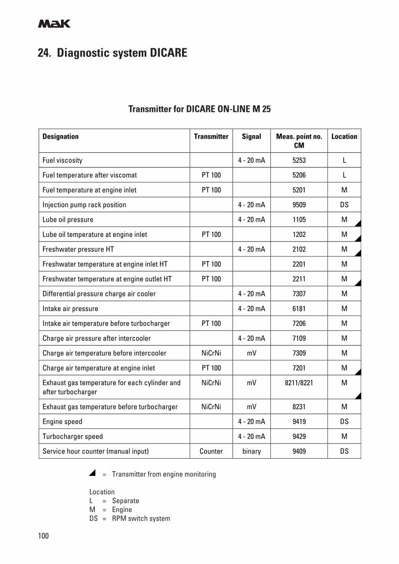
m
100
24. Diagnostic system DICARE
Transmitter for DICARE ON-LINE M 25
= Transmitter from engine monitoring
LocationL = SeparateM = EngineDS = RPM switch system
Designation Transmitter Signal Meas. point no. CM
Location
Fuel viscosity 4 - 20 mA 5253 L
Fuel temperature after viscomat PT 100 5206 L
Fuel temperature at engine inlet PT 100 5201 M
Injection pump rack position 4 - 20 mA 9509 DS
Lube oil pressure 4 - 20 mA 1105 M
Lube oil temperature at engine inlet PT 100 1202 M
Freshwater pressure HT 4 - 20 mA 2102 M
Freshwater temperature at engine inlet HT PT 100 2201 M
Freshwater temperature at engine outlet HT PT 100 2211 M
Differential pressure charge air cooler 4 - 20 mA 7307 M
Intake air pressure 4 - 20 mA 6181 M
Intake air temperature before turbocharger PT 100 7206 M
Charge air pressure after intercooler 4 - 20 mA 7109 M
Charge air temperature before intercooler NiCrNi mV 7309 M
Charge air temperature at engine inlet PT 100 7201 M
Exhaust gas temperature for each cylinder and after turbocharger
NiCrNi mV 8211/8221 M
Exhaust gas temperature before turbocharger NiCrNi mV 8231 M
Engine speed 4 - 20 mA 9419 DS
Turbocharger speed 4 - 20 mA 9429 M
Service hour counter (manual input) Counter binary 9409 DS
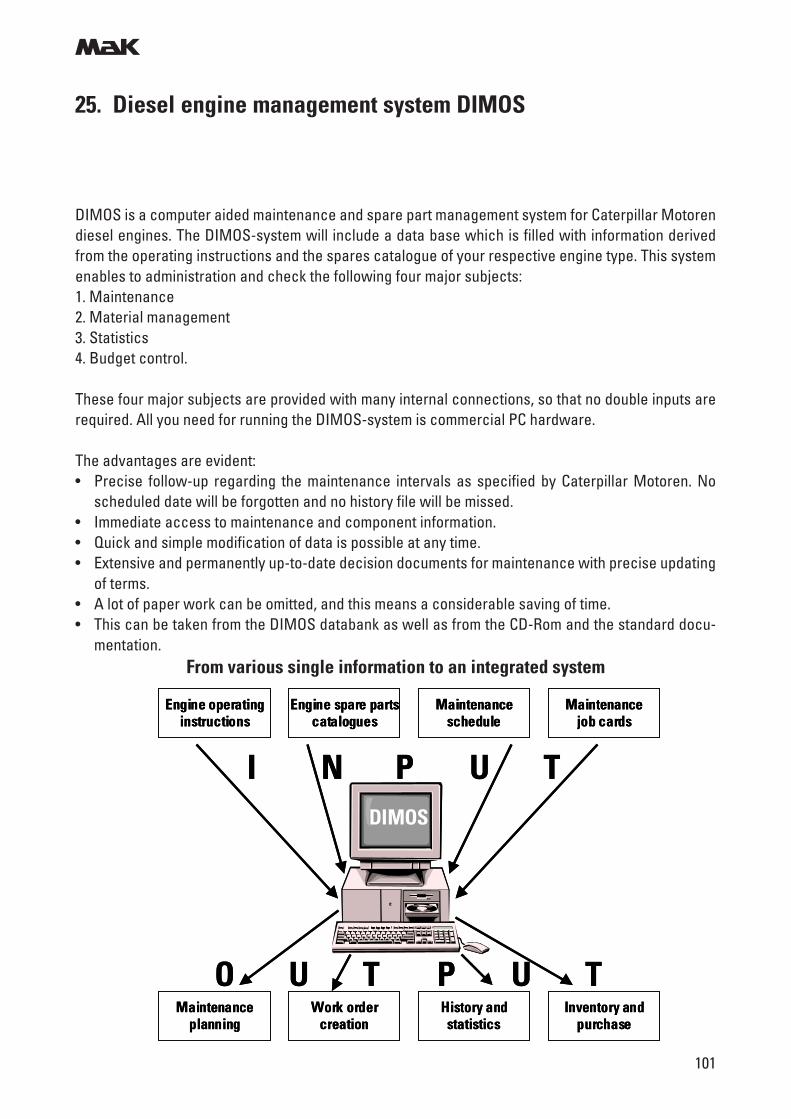
m
101
25. Diesel engine management system DIMOS
DIMOS is a computer aided maintenance and spare part management system for Caterpillar Motorendiesel engines. The DIMOS-system will include a data base which is filled with information derivedfrom the operating instructions and the spares catalogue of your respective engine type. This systemenables to administration and check the following four major subjects:1. Maintenance2. Material management3. Statistics4. Budget control.
These four major subjects are provided with many internal connections, so that no double inputs arerequired. All you need for running the DIMOS-system is commercial PC hardware.
The advantages are evident:• Precise follow-up regarding the maintenance intervals as specified by Caterpillar Motoren. No
scheduled date will be forgotten and no history file will be missed.• Immediate access to maintenance and component information.• Quick and simple modification of data is possible at any time.• Extensive and permanently up-to-date decision documents for maintenance with precise updating
of terms.• A lot of paper work can be omitted, and this means a considerable saving of time.• This can be taken from the DIMOS databank as well as from the CD-Rom and the standard docu-
mentation.From various single information to an integrated system
DIMOS
Engine operatinginstructions
Engine spare partscatalogues
Maintenanceschedule
Maintenancejob cards
Maintenanceplanning
Work ordercreation
History andstatistics
Inventory andpurchase
O U T P U T
I N P U TDIMOS
Engine operatinginstructions
Engine spare partscatalogues
Maintenanceschedule
Maintenancejob cards
Maintenanceplanning
Work ordercreation
History andstatistics
Inventory andpurchase
O U T P U T
I N P U T
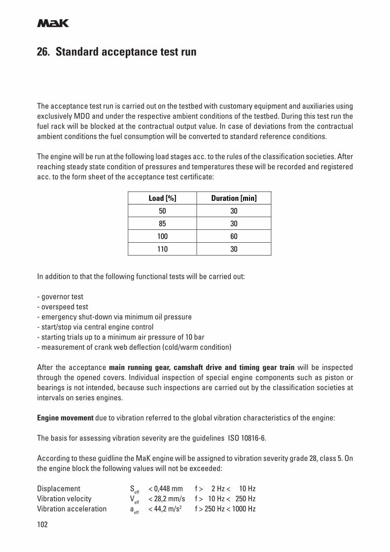
m
102
26. Standard acceptance test run
In addition to that the following functional tests will be carried out:
- governor test- overspeed test- emergency shut-down via minimum oil pressure- start/stop via central engine control- starting trials up to a minimum air pressure of 10 bar- measurement of crank web deflection (cold/warm condition)
After the acceptance main running gear, camshaft drive and timing gear train will be inspectedthrough the opened covers. Individual inspection of special engine components such as piston orbearings is not intended, because such inspections are carried out by the classification societies atintervals on series engines.
Engine movement due to vibration referred to the global vibration characteristics of the engine:
The basis for assessing vibration severity are the guidelines ISO 10816-6.
According to these guidline the MaK engine will be assigned to vibration severity grade 28, class 5. Onthe engine block the following values will not be exceeded:
Displacement Seff < 0,448 mm f > 2 Hz < 10 HzVibration velocity Veff < 28,2 mm/s f > 10 Hz < 250 HzVibration acceleration aeff < 44,2 m/s2 f > 250 Hz < 1000 Hz
The acceptance test run is carried out on the testbed with customary equipment and auxiliaries usingexclusively MDO and under the respective ambient conditions of the testbed. During this test run thefuel rack will be blocked at the contractual output value. In case of deviations from the contractualambient conditions the fuel consumption will be converted to standard reference conditions.
The engine will be run at the following load stages acc. to the rules of the classification societies. Afterreaching steady state condition of pressures and temperatures these will be recorded and registeredacc. to the form sheet of the acceptance test certificate:
Load [%] Duration [min]
50 30
85 30
100 60
110 30
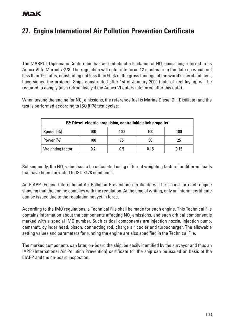
m
103
27. Engine International Air Pollution Prevention Certificate
The MARPOL Diplomatic Conference has agreed about a limitation of NOx emissions, referred to asAnnex VI to Marpol 73/78. The regulation will enter into force 12 months from the date on which notless than 15 states, constituting not less than 50 % of the gross tonnage of the world's merchant fleet,have signed the protocol. Ships constructed after 1st of January 2000 (date of keel-laying) will berequired to comply (also retroactively if the Annex VI enters into force after this date).
When testing the engine for NOx emissions, the reference fuel is Marine Diesel Oil (Distillate) and thetest is performed according to ISO 8178 test cycles:
Subsequently, the NOx value has to be calculated using different weighting factors for different loadsthat have been corrected to ISO 8178 conditions.
An EIAPP (Engine International Air Pollution Prevention) certificate will be issued for each engineshowing that the engine complies with the regulation. At the time of writing, only an interim certificatecan be issued due to the regulation not yet in force.
According to the IMO regulations, a Technical File shall be made for each engine. This Technical Filecontains information about the components affecting NOx emissions, and each critical component ismarked with a special IMO number. Such critical components are injection nozzle, injection pump,camshaft, cylinder head, piston, connecting rod, charge air cooler and turbocharger. The allowablesetting values and parameters for running the engine are also specified in the Technical File.
The marked components can later, on-board the ship, be easily identified by the surveyor and thus anIAPP (International Air Pollution Prevention) certificate for the ship can be issued on basis of theEIAPP and the on-board inspection.
E2: Diesel-electric propulsion, controllable pitch propeller
Speed [%] 100 100 100 100
Power [%] 100 75 50 25
Weighting factor 0.2 0.5 0.15 0.15
m
104
28. Painting/Preservation
Outside Preservation, Light N 576-3.1up to 6 months, within Europe.For transportation and outdoor storage (protected from moisture)
Appearance of the engine:- Castings with red oxide antirust paint- Pipes and machined surfaces left as bare metal- Attached components painted in the colours of the makers- Corrosion protection with Tectyl 846K19
Outside Preservation, Heavy-Duty N 576-3.2up to 12 months outside of EuropeFor transportation and outdoor storage (protected from moisture)
Appearance of the engine:- Castings with red oxide antirust paint- Pipes and machined surfaces left as bare metal- Attached components painted in the colours of the makers- Corrosion protection with Tectyl 506EH
Inside Preservation N 576-3.3up to 1 year, protected from moisture.
- Main running gear and inner mechanics
Engine with Clear Varnish N 576-4.1without additional measures no outdoor storage.For shipment and outdoor storage (protected from moisture) an additional corrosion protection is re-quired!
Appearance of the engine:- Castings with red oxide antirust paint- Pipes and machined surfaces left as bare metal- Attached components painted in the colours of the makers- Surfaces sealed with clear varnish
m
105
Engine with Grey Primer N 576-4.2without additional measures no outdoor storage.For shipment and outdoor storage (protected from moisture) an additional corrosion protection is re-quired!
Appearance of the engine:- Surfaces mostly with grey primer
Engine with Coat of Varnish N 576-4.3without additional measures no outdoor storage.For shipment and outdoor storage (protected from moisture) an additional corrosion protection is re-quired!
Appearance of the engine:- Surfaces mostly painted with varnish.
28. Painting/Preservation
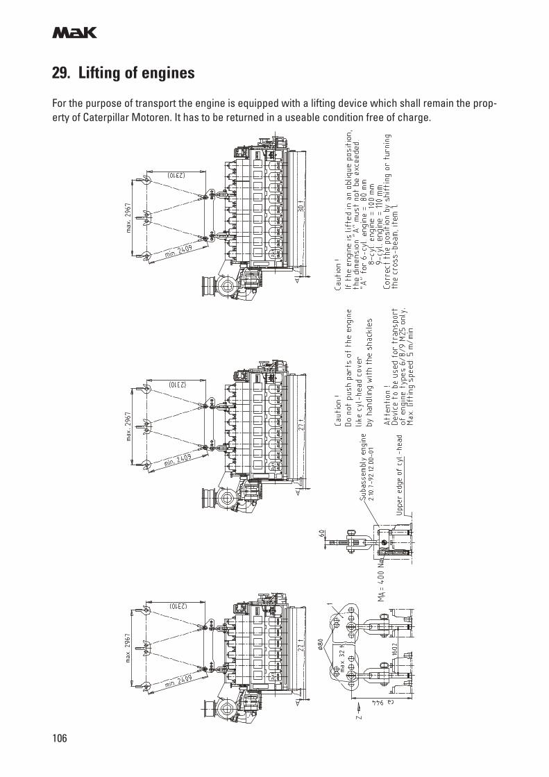
m
106
29. Lifting of engines
For the purpose of transport the engine is equipped with a lifting device which shall remain the prop-erty of Caterpillar Motoren. It has to be returned in a useable condition free of charge.
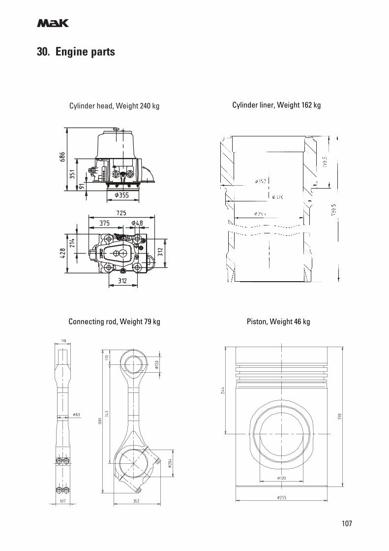
m
107
30. Engine parts
Cylinder head, Weight 240 kg
Connecting rod, Weight 79 kg Piston, Weight 46 kg
Cylinder liner, Weight 162 kg
For more information please visit our website:www.cat-marine.com or www.mak-global.com
Caterpillar Marine Power SystemsEurope, Africa, Middle East
Caterpillar MarinePower SystemsNeumühlen 922763 Hamburg/Germany
Phone: +49 40 2380-3000Telefax: +49 40 2380-3535
Caterpillar Marine AsiaPacific Pte Ltd14 Tractor RoadSingapore627973/SingaporePhone: +65 68287-600Telefax: +65 68287-624
Americas
MaK Americas Inc.
3450 Executive WayMiramar Park of CommerceMiramar, FL. 33025/USAPhone: +1 954 447 71 00Telefax: +1 954 447 71 15
Caterpillar Marine Trading(Shanghai) Co., Ltd.Rm 2309, Lippo Plaza222, Huai Hai Zhong Road200021 Shanghai/P. R.ChinaPhone: +86 21 5396 5577Telefax: +86 21 5396 7007
Asia PacificHeadquarters
Caterpillar MarinePower SystemsNeumühlen 922763 Hamburg/Germany
Phone: +49 40 2380-3000Telefax: +49 40 2380-3535
Subject to change without notice.Leaflet No. 229 · 04.04 · e · G+D · VM3