Embed Size (px)
Citation preview

Electrical Machines Lab Third Year M2: DC Machines
Faculty of Engineering Cairo University Electrical Power and Machines Dept.
1
M2 DC Machines
I. Objectives This Experiment aims to observing the operation ad characteristics of the:
1. Separately excited DC generator. 2. Shunt excited DC generator. 3. Shunt excited DC motor. 4. Series excited DC motor.
II. Background
Small DC machines (fractional HP) are used as control devices such as tacho-generator and servomotors. Large DC machines are used in industry. A wide variety of volt-ampere or torque-speed characteristics can be obtained from various connections of the field windings. The DC machine is extensively used as a motor in industry. Its speed can be controlled over a wide range with relative ease. The most common speed control methods are adjustment of the flux usually be means of field current control, armature current control and adjustment of the armature terminal voltage.
III. Procedure Test 1: The external characteristic of a separately excited DC generator The experiment setup is as shown in Fig. (1) 1. Run the generator with the help of shunt motor at rated speed. 2. Switch on DC supply to the field winding of a separately excited DC generator and pass a
small current by changing the setting of the field rheostat. 3. Read the generator terminal voltage at different values of field current at constant speed. 4. Adjust the field rheostat to obtain rated generator voltage. 5. Close the resistive load switch and change the load of the generator with the help of
loading rheostat. 6. Read the load current and the terminal voltage. 7. Reduce the supply voltage to obtain another value of motor speed. 8. Repeat the above steps. Test 2: The external characteristic of a DC shunt generator 1. Connect as shown in Fig. (2). 2. Run the motor and bring it to its rated speed. 3. Adjust the field resistance of the generator so that the generator builds up its rated
voltage. 4. Close the load switch and change the load of the generator. 5. Check the speed, adjust it to rated value, and record the load current and terminal
voltage. 6. Reduce load and field current gradually. 7. Switch off the load. 8. Stop the motor.

Electrical Machines Lab Third Year M2: DC Machines
Faculty of Engineering Cairo University Electrical Power and Machines Dept.
2
Test 3: The external characteristic of a DC shunt motor 1. Connect as shown in fig. (2). 2. At starting, a rated voltage is applied at the armature terminals. Increase the supply
voltage gradually until the motor builds up its rated speed. 3. Adjust the field rheostat of the generator to obtain rated voltage. 4. Load the generator, keeping its terminal voltage constant with the help of field rheostat. 5. Read the input voltage, current and speed. 6. Change the supply voltage and repeat the above steps.
Test 4: The external characteristic of a DC series motor 1. Connect as shown in fig. (3). 2. Set the generator field rheostat a lower value and keep suitable loading rheostat in the
circuit. 3. Switch on the DC supply and start the motor at reduced supply voltage. 4. At the time of starting, care should be taken, the generator builds up and is loaded to
some value so that the speed is within limit. 5. Adjust the field current of the generator to obtain rated voltage. 6. Change the load of the generator with the help of loading rheostat. 7. Read the input voltage, current and speed.
IV. Report
Test 1: - Plot generator O.C. terminal voltage versus the field current at rated speed. - Plot the external characteristic of the separately excited DC generator (VL – IL). Test 2:
- Plot the external characteristic of the DC shunt generator (VL – IL). Test 3:
- Plot the external characteristic of the DC shunt motor (n – IM) for several supply voltage values. - Plot the speed of the motor against the supply voltage.
Test 4 - Plot the external characteristic of the DC series motor (n – IM). Discuss the above results and comment on the main points

Electrical Machines Lab Third Year M2: DC Machines
Faculty of Engineering Cairo University Electrical Power and Machines Dept.
3
Connection Diagrams

Electrical Machines Lab Third Year M2: DC Machines
Faculty of Engineering Cairo University Electrical Power and Machines Dept.
4
M2: DC Machines Lab results
1. Magnetization Curve
n =
If (A) 0
E (V)
2. Separately excited DC generator n =
IL ( Ia ) (A) 0
VL (V) 200
3. Shunt excited DC generator n =
IL (A) 0
VL (V) 200
4. Shunt excited DC Motor At Vs = 200 V
Ia (A)
n (rpm)
At Vs = 150 V
Ia (A)
n (rpm)
5. Series DC Motor At Vs = 150 V
Ia (A)
n (rpm)

Electrical Machines Lab Third Year M2: DC Machines
Faculty of Engineering Cairo University Electrical Power and Machines Dept.
5
Magnetization curve

Electrical Machines Lab Third Year M2: DC Machines
Faculty of Engineering Cairo University Electrical Power and Machines Dept.
6
External characteristics of separately excited DC generator and shunt DC generator

Electrical Machines Lab Third Year M2: DC Machines
Faculty of Engineering Cairo University Electrical Power and Machines Dept.
7
External characteristics of DC shunt motor and DC series motor

Electrical Machines Lab Third Year M2: DC Machines
Faculty of Engineering Cairo University Electrical Power and Machines Dept.
8
Appendix of DC Machine Lab (M2)
A) Sample of rating plate of a DC motor (Siemens)
Where,

Electrical Machines Lab Third Year M2: DC Machines
Faculty of Engineering Cairo University Electrical Power and Machines Dept.
9
B) Sample of faults and its countermeasures
1. Faults in operation
Electrical Machines Lab Third Year M2: DC Machines
Faculty of Engineering Cairo University Electrical Power and Machines Dept.
10
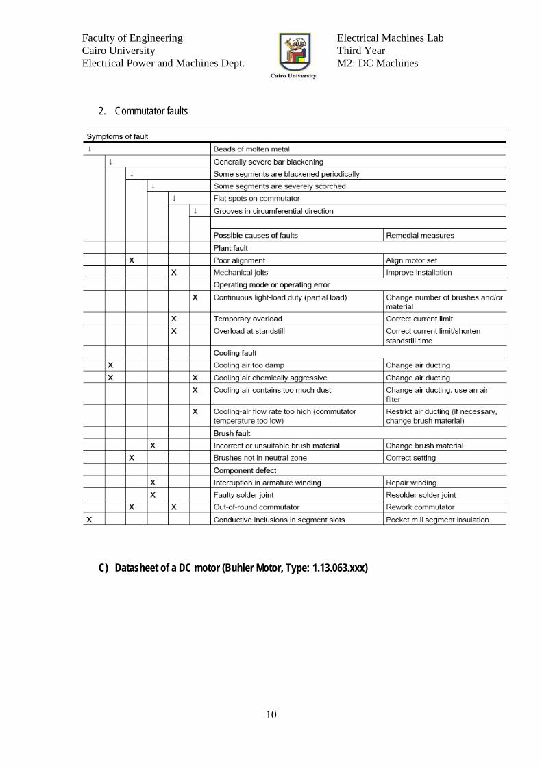
2. Commutator faults
C) Datasheet of a DC motor (Buhler Motor, Type: 1.13.063.xxx)

STOCK SERVICE
DC Motor Ø 64 1.13.063.XXX
1.13.063.XXX
Design
Commutator Copper/12-segments
RFI Protection 2 chokes
Insulation class Winding H, otherwise A
Protection class IP40
Commutation carbon brushes
Armature straight slot
Magnet system Permanent magnets, 2-pole
Bearings 2 preloaded ball bearings
Housing Steel, corrosion protected
End shields zinc die-cast on both sides
Type 1.13.063.XXX 220 221 407 408
Characteristics*
Rated voltage V V 12 24 12 24
Rated power PN
W 115 115 150 150
Rated torque TN
mNm 350 350 400 400
Rated speed nN
rpm 3150 3150 3400 3400
Rated current IN
A 15 7.5 17 8.5
No load characteristics*
No load speed nO
rpm 3700 3700 3900 3900
No load current IO
A 2.6 1.3 2.0 1.0
Starting characteristics*
Starting torque TS
mNm 2500 2500 3400 3400
Starting current IS
A 95 47 128 64
Performance characteristics*
max. Output power Pmax
W 230 230 340 340
max. Constant torque Tmax
mNm 350 350 400 400
Motor parameters*
Weight G g 1300 1300 1600 1600
Rotor inertia J gcm2 850 850 1050 1050
Terminal resistance R Ohm 0.125 0.5 0.1 0.4
Mech. time constant τm
ms 15 15 11 11
Electr. time constant τe
ms 2.0 2.0 2.5 2.5
Speed regulation constant Rm
rpm/mNm 1.5 1.5 1.02 0.98
Torque constant kM
mNm/A 27 54 27 54
Thermal resistance Rth1
K/W 2.8 2.8 2.5 2.5
Thermal resistance Rth2
K/W 3.3 3.3 3.0 3.0
Axial play < 0.1 < 0.1 < 0.1 < 0.1
Direction of rotation bidirectional

1.13.063.XXX
Operational conditions
Temperature range T °C -10 - +70
Axial force FA
N 50
Radial force, 15 mm from mounting surface FR
N 200
* at 25 °C
Customized versions
The following modifi cations are available upon request: 3 Encoder possible
3 Internal chokes and/or capacitors
3 Speed adjustment by winding change
3 Modifi cation of shaft length on both ends
3 Modifi cation of shaft confi guration (fl at, groove, etc.)
3 Assembly of gears, pinions, worms, etc.
3 Assembly of adapters and mounting plates
3 Reduced cogging torque possible