Embed Size (px)
Citation preview
MICROTEC S.r.l.
Via Avris 3 – 21032 CARAVATE (VA) ITALY – C.F. – P.IVA 02356120127 – Reg. Imprese 24798/1997 VA
Tel. +39 0332 601731 – Fax +39 0332 771777
M197 Ducati Engine Control Software version Professional 1.2b
Rev 1.01
MICROTEC S.R.L. Via Avris 3
21032 Caravate (VA) ITALY
Tel – 0332601731 Fax – 0332771777
Email – [email protected] Web – www.microtec.cc
MICROTEC S.r.l.
Via Avris 3 – 21032 CARAVATE (VA) ITALY – C.F. – P.IVA 02356120127 – Reg. Imprese 24798/1997 VA
Tel. +39 0332 601731 – Fax +39 0332 771777
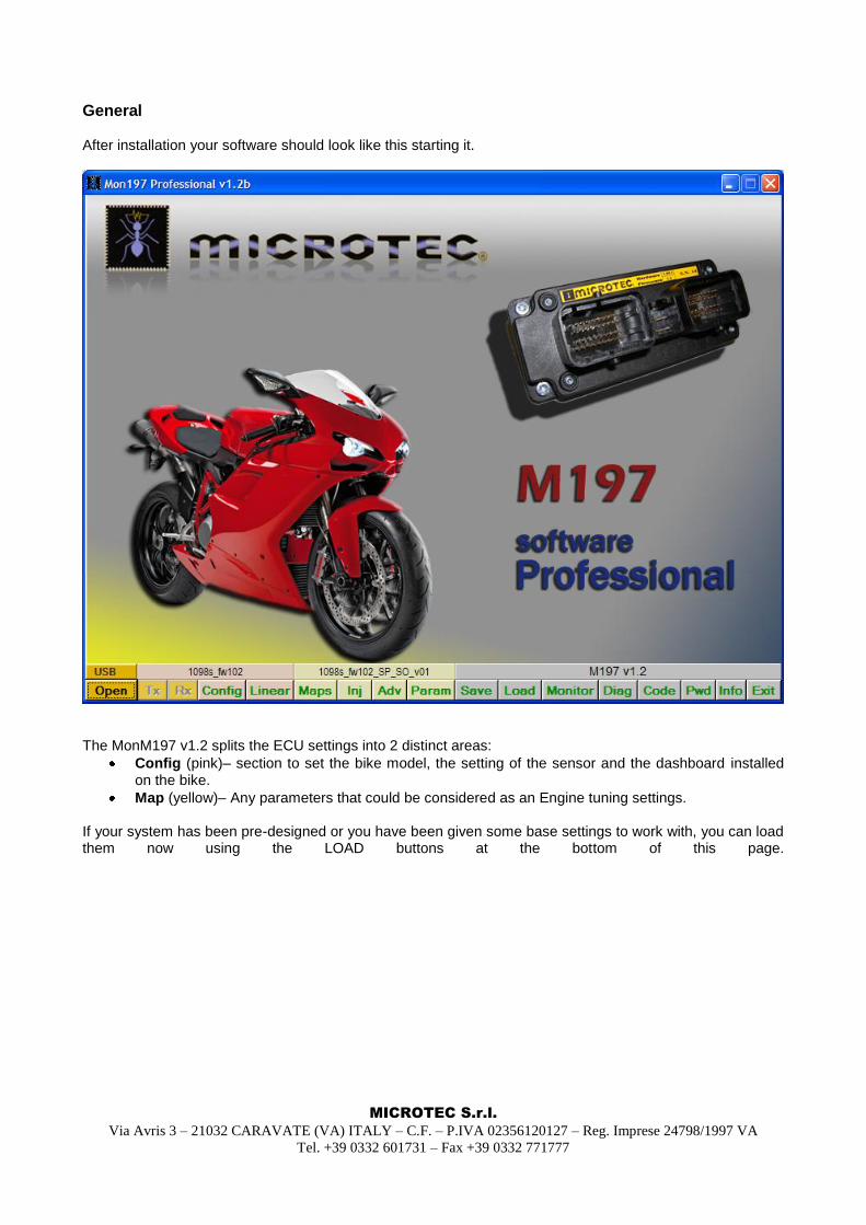
General After installation your software should look like this starting it.
The MonM197 v1.2 splits the ECU settings into 2 distinct areas:
Config (pink)– section to set the bike model, the setting of the sensor and the dashboard installed on the bike.
Map (yellow)– Any parameters that could be considered as an Engine tuning settings. If your system has been pre-designed or you have been given some base settings to work with, you can load them now using the LOAD buttons at the bottom of this page.
MICROTEC S.r.l.
Via Avris 3 – 21032 CARAVATE (VA) ITALY – C.F. – P.IVA 02356120127 – Reg. Imprese 24798/1997 VA
Tel. +39 0332 601731 – Fax +39 0332 771777
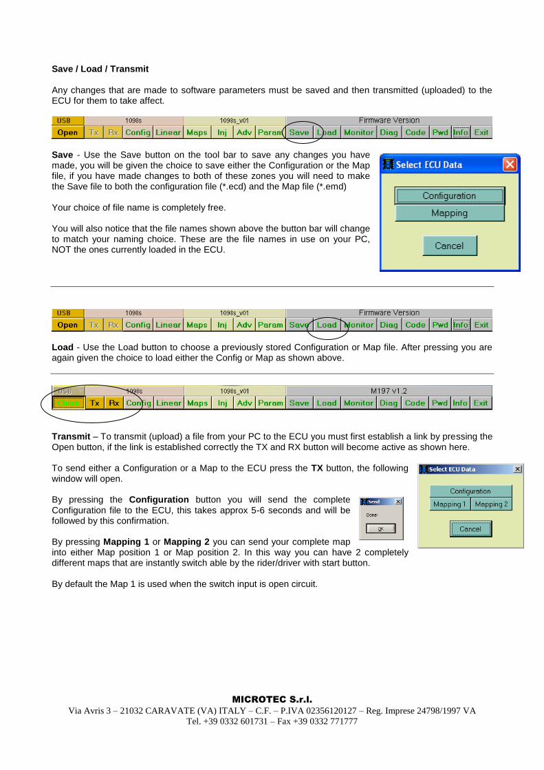
Save / Load / Transmit Any changes that are made to software parameters must be saved and then transmitted (uploaded) to the ECU for them to take affect.
Save - Use the Save button on the tool bar to save any changes you have made, you will be given the choice to save either the Configuration or the Map file, if you have made changes to both of these zones you will need to make the Save file to both the configuration file (*.ecd) and the Map file (*.emd) Your choice of file name is completely free. You will also notice that the file names shown above the button bar will change to match your naming choice. These are the file names in use on your PC, NOT the ones currently loaded in the ECU.
Load - Use the Load button to choose a previously stored Configuration or Map file. After pressing you are again given the choice to load either the Config or Map as shown above.
Transmit – To transmit (upload) a file from your PC to the ECU you must first establish a link by pressing the Open button, if the link is established correctly the TX and RX button will become active as shown here. To send either a Configuration or a Map to the ECU press the TX button, the following window will open. By pressing the Configuration button you will send the complete Configuration file to the ECU, this takes approx 5-6 seconds and will be followed by this confirmation. By pressing Mapping 1 or Mapping 2 you can send your complete map into either Map position 1 or Map position 2. In this way you can have 2 completely different maps that are instantly switch able by the rider/driver with start button. By default the Map 1 is used when the switch input is open circuit.
MICROTEC S.r.l.
Via Avris 3 – 21032 CARAVATE (VA) ITALY – C.F. – P.IVA 02356120127 – Reg. Imprese 24798/1997 VA
Tel. +39 0332 601731 – Fax +39 0332 771777
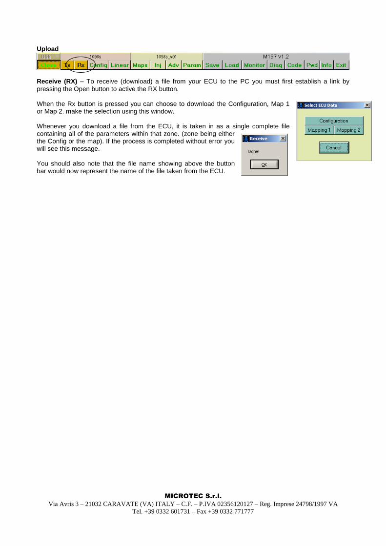
Upload
Receive (RX) – To receive (download) a file from your ECU to the PC you must first establish a link by pressing the Open button to active the RX button. When the Rx button is pressed you can choose to download the Configuration, Map 1 or Map 2. make the selection using this window. Whenever you download a file from the ECU, it is taken in as a single complete file containing all of the parameters within that zone. (zone being either the Config or the map). If the process is completed without error you will see this message. You should also note that the file name showing above the button bar would now represent the name of the file taken from the ECU.
MICROTEC S.r.l.
Via Avris 3 – 21032 CARAVATE (VA) ITALY – C.F. – P.IVA 02356120127 – Reg. Imprese 24798/1997 VA
Tel. +39 0332 601731 – Fax +39 0332 771777
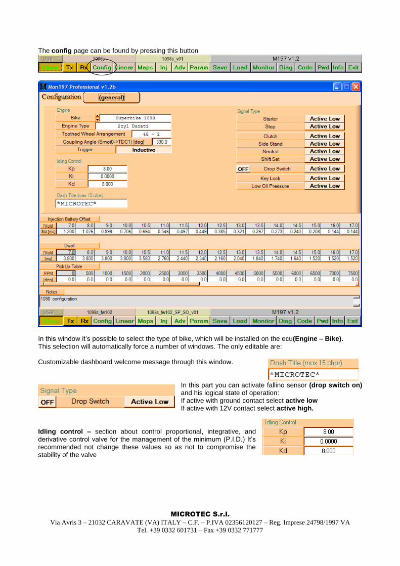
The config page can be found by pressing this button
In this window it‟s possible to select the type of bike, which will be installed on the ecu(Engine – Bike). This selection will automatically force a number of windows. The only editable are: Customizable dashboard welcome message through this window.
In this part you can activate fallino sensor (drop switch on) and his logical state of operation: If active with ground contact select active low If active with 12V contact select active high.
Idling control – section about control proportional, integrative, and derivative control valve for the management of the minimum (P.I.D.) It‟s recommended not change these values so as not to compromise the stability of the valve
MICROTEC S.r.l.
Via Avris 3 – 21032 CARAVATE (VA) ITALY – C.F. – P.IVA 02356120127 – Reg. Imprese 24798/1997 VA
Tel. +39 0332 601731 – Fax +39 0332 771777
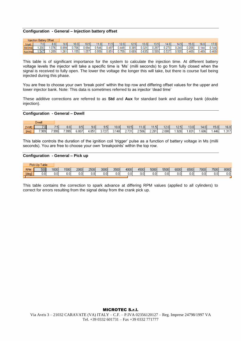
Configuration - General – Injection battery offset
This table is of significant importance for the system to calculate the injection time. At different battery voltage levels the injector will take a specific time is „Ms‟ (milli seconds) to go from fully closed when the signal is received to fully open. The lower the voltage the longer this will take, but there is course fuel being injected during this phase. You are free to choose your own „break point‟ within the top row and differing offset values for the upper and lower injector bank. Note: This data is sometimes referred to as injector „dead time‟ These additive corrections are referred to as Std and Aux for standard bank and auxiliary bank (double injection).
Configuration - General – Dwell
This table controls the duration of the ignition coil „trigger‟ pulse as a function of battery voltage in Ms (milli seconds). You are free to choose your own „breakpoints‟ within the top row.
Configuration - General – Pick up
This table contains the correction to spark advance at differing RPM values (applied to all cylinders) to correct for errors resulting from the signal delay from the crank pick up.
MICROTEC S.r.l.
Via Avris 3 – 21032 CARAVATE (VA) ITALY – C.F. – P.IVA 02356120127 – Reg. Imprese 24798/1997 VA
Tel. +39 0332 601731 – Fax +39 0332 771777
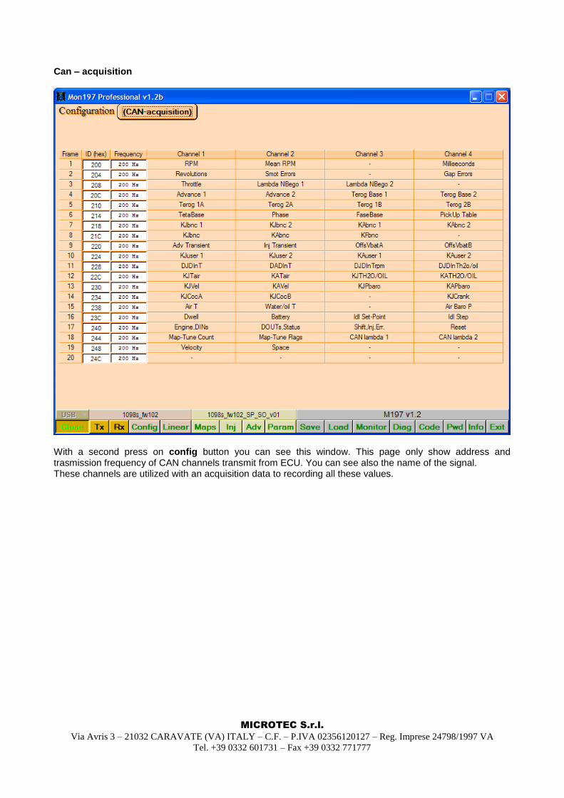
Can – acquisition
With a second press on config button you can see this window. This page only show address and trasmission frequency of CAN channels transmit from ECU. You can see also the name of the signal. These channels are utilized with an acquisition data to recording all these values.
MICROTEC S.r.l.
Via Avris 3 – 21032 CARAVATE (VA) ITALY – C.F. – P.IVA 02356120127 – Reg. Imprese 24798/1997 VA
Tel. +39 0332 601731 – Fax +39 0332 771777
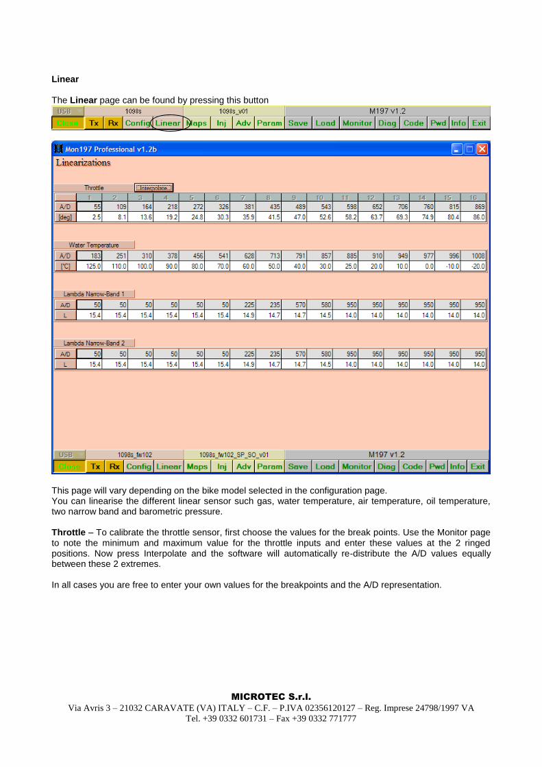
Linear The Linear page can be found by pressing this button
This page will vary depending on the bike model selected in the configuration page. You can linearise the different linear sensor such gas, water temperature, air temperature, oil temperature, two narrow band and barometric pressure. Throttle – To calibrate the throttle sensor, first choose the values for the break points. Use the Monitor page to note the minimum and maximum value for the throttle inputs and enter these values at the 2 ringed positions. Now press Interpolate and the software will automatically re-distribute the A/D values equally between these 2 extremes. In all cases you are free to enter your own values for the breakpoints and the A/D representation.
MICROTEC S.r.l.
Via Avris 3 – 21032 CARAVATE (VA) ITALY – C.F. – P.IVA 02356120127 – Reg. Imprese 24798/1997 VA
Tel. +39 0332 601731 – Fax +39 0332 771777
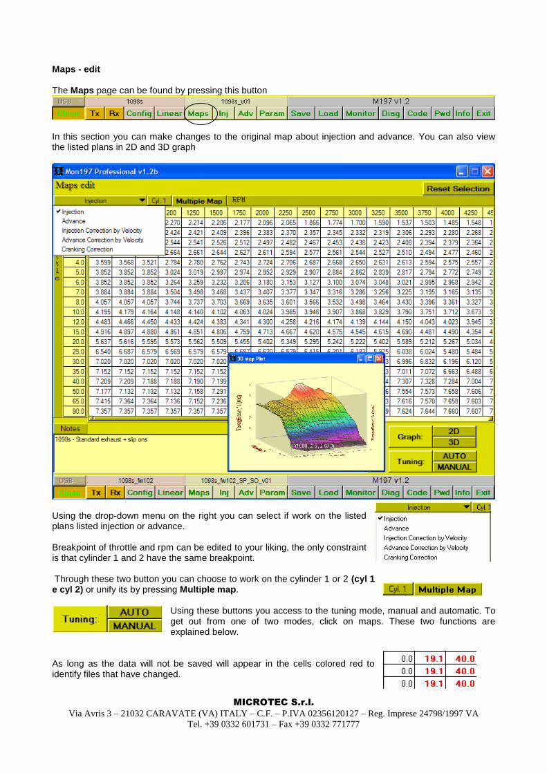
Maps - edit The Maps page can be found by pressing this button
In this section you can make changes to the original map about injection and advance. You can also view the listed plans in 2D and 3D graph
Using the drop-down menu on the right you can select if work on the listed plans listed injection or advance. Breakpoint of throttle and rpm can be edited to your liking, the only constraint is that cylinder 1 and 2 have the same breakpoint. Through these two button you can choose to work on the cylinder 1 or 2 (cyl 1 e cyl 2) or unify its by pressing Multiple map.
Using these buttons you access to the tuning mode, manual and automatic. To get out from one of two modes, click on maps. These two functions are explained below.
As long as the data will not be saved will appear in the cells colored red to identify files that have changed.
MICROTEC S.r.l.
Via Avris 3 – 21032 CARAVATE (VA) ITALY – C.F. – P.IVA 02356120127 – Reg. Imprese 24798/1997 VA
Tel. +39 0332 601731 – Fax +39 0332 771777
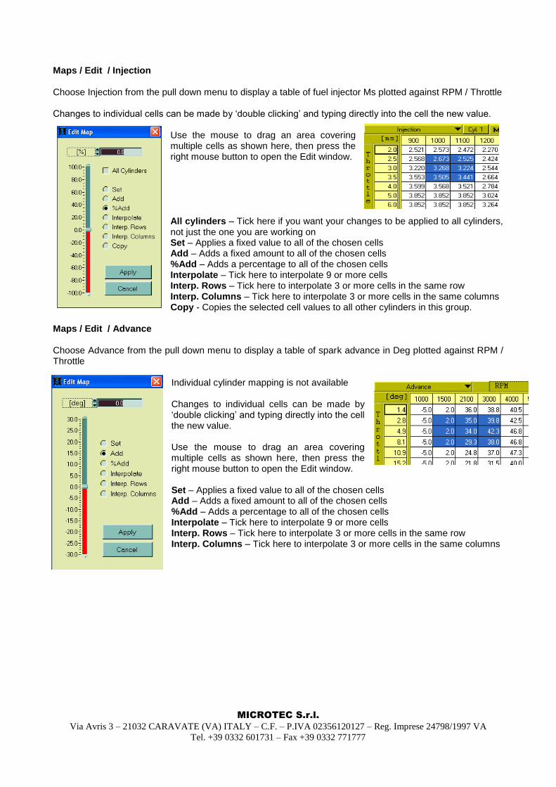
Maps / Edit / Injection Choose Injection from the pull down menu to display a table of fuel injector Ms plotted against RPM / Throttle Changes to individual cells can be made by „double clicking‟ and typing directly into the cell the new value.
Use the mouse to drag an area covering multiple cells as shown here, then press the right mouse button to open the Edit window. All cylinders – Tick here if you want your changes to be applied to all cylinders, not just the one you are working on Set – Applies a fixed value to all of the chosen cells Add – Adds a fixed amount to all of the chosen cells %Add – Adds a percentage to all of the chosen cells Interpolate – Tick here to interpolate 9 or more cells Interp. Rows – Tick here to interpolate 3 or more cells in the same row Interp. Columns – Tick here to interpolate 3 or more cells in the same columns Copy - Copies the selected cell values to all other cylinders in this group.
Maps / Edit / Advance Choose Advance from the pull down menu to display a table of spark advance in Deg plotted against RPM / Throttle
Individual cylinder mapping is not available Changes to individual cells can be made by „double clicking‟ and typing directly into the cell the new value. Use the mouse to drag an area covering multiple cells as shown here, then press the right mouse button to open the Edit window. Set – Applies a fixed value to all of the chosen cells Add – Adds a fixed amount to all of the chosen cells %Add – Adds a percentage to all of the chosen cells Interpolate – Tick here to interpolate 9 or more cells Interp. Rows – Tick here to interpolate 3 or more cells in the same row Interp. Columns – Tick here to interpolate 3 or more cells in the same columns
MICROTEC S.r.l.
Via Avris 3 – 21032 CARAVATE (VA) ITALY – C.F. – P.IVA 02356120127 – Reg. Imprese 24798/1997 VA
Tel. +39 0332 601731 – Fax +39 0332 771777
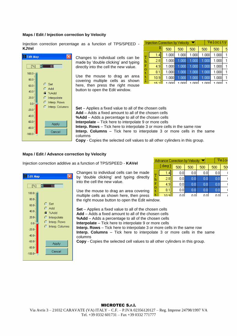
Maps / Edit / Injection correction by Velocity Injection correction percentage as a function of TPS/SPEED - KJVel
Changes to individual cells can be made by „double clicking‟ and typing directly into the cell the new value. Use the mouse to drag an area covering multiple cells as shown here, then press the right mouse button to open the Edit window. Set – Applies a fixed value to all of the chosen cells Add – Adds a fixed amount to all of the chosen cells %Add – Adds a percentage to all of the chosen cells Interpolate – Tick here to interpolate 9 or more cells Interp. Rows – Tick here to interpolate 3 or more cells in the same row Interp. Columns – Tick here to interpolate 3 or more cells in the same columns Copy - Copies the selected cell values to all other cylinders in this group.
Maps / Edit / Advance correction by Velocity Injection correction additive as a function of TPS/SPEED - KAVel
Changes to individual cells can be made by „double clicking‟ and typing directly into the cell the new value. Use the mouse to drag an area covering multiple cells as shown here, then press the right mouse button to open the Edit window. Set – Applies a fixed value to all of the chosen cells Add – Adds a fixed amount to all of the chosen cells %Add – Adds a percentage to all of the chosen cells Interpolate – Tick here to interpolate 9 or more cells Interp. Rows – Tick here to interpolate 3 or more cells in the same row Interp. Columns – Tick here to interpolate 3 or more cells in the same columns Copy - Copies the selected cell values to all other cylinders in this group.
MICROTEC S.r.l.
Via Avris 3 – 21032 CARAVATE (VA) ITALY – C.F. – P.IVA 02356120127 – Reg. Imprese 24798/1997 VA
Tel. +39 0332 601731 – Fax +39 0332 771777
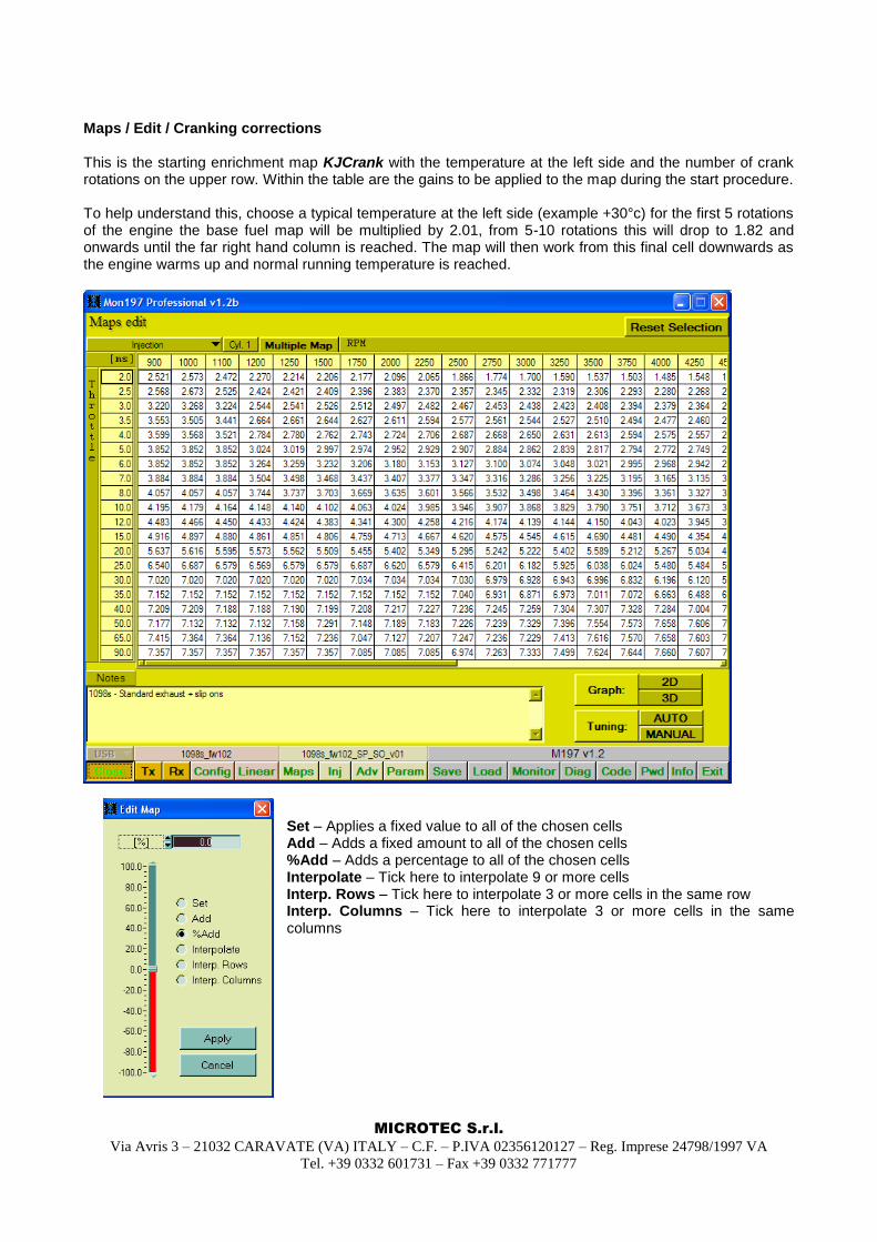
Maps / Edit / Cranking corrections This is the starting enrichment map KJCrank with the temperature at the left side and the number of crank rotations on the upper row. Within the table are the gains to be applied to the map during the start procedure. To help understand this, choose a typical temperature at the left side (example +30°c) for the first 5 rotations of the engine the base fuel map will be multiplied by 2.01, from 5-10 rotations this will drop to 1.82 and onwards until the far right hand column is reached. The map will then work from this final cell downwards as the engine warms up and normal running temperature is reached.
Set – Applies a fixed value to all of the chosen cells Add – Adds a fixed amount to all of the chosen cells %Add – Adds a percentage to all of the chosen cells Interpolate – Tick here to interpolate 9 or more cells Interp. Rows – Tick here to interpolate 3 or more cells in the same row Interp. Columns – Tick here to interpolate 3 or more cells in the same columns
MICROTEC S.r.l.
Via Avris 3 – 21032 CARAVATE (VA) ITALY – C.F. – P.IVA 02356120127 – Reg. Imprese 24798/1997 VA
Tel. +39 0332 601731 – Fax +39 0332 771777
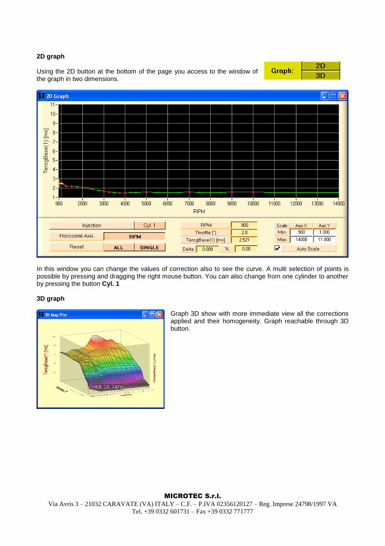
2D graph Using the 2D button at the bottom of the page you access to the window of the graph in two dimensions.
In this window you can change the values of correction also to see the curve. A multi selection of points is possible by pressing and dragging the right mouse button. You can also change from one cylinder to another by pressing the button Cyl. 1 3D graph
Graph 3D show with more immediate view all the corrections applied and their homogeneity. Graph reachable through 3D button.
MICROTEC S.r.l.
Via Avris 3 – 21032 CARAVATE (VA) ITALY – C.F. – P.IVA 02356120127 – Reg. Imprese 24798/1997 VA
Tel. +39 0332 601731 – Fax +39 0332 771777
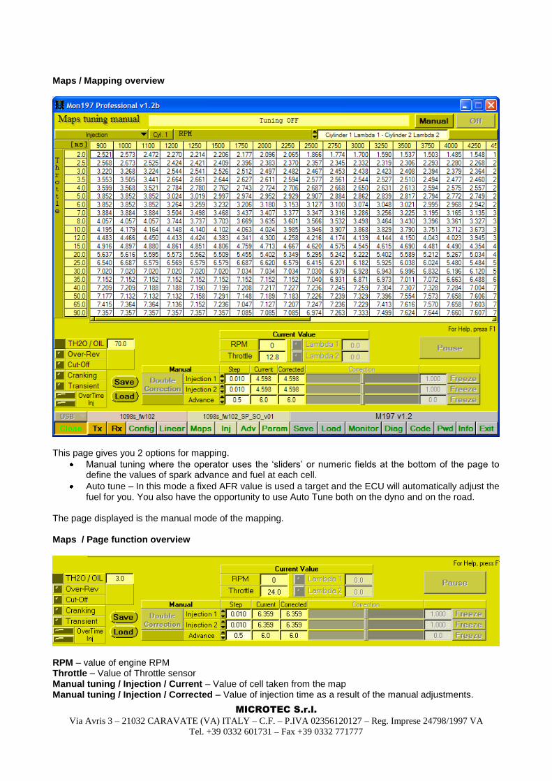
Maps / Mapping overview
This page gives you 2 options for mapping.
Manual tuning where the operator uses the „sliders‟ or numeric fields at the bottom of the page to define the values of spark advance and fuel at each cell.
Auto tune – In this mode a fixed AFR value is used a target and the ECU will automatically adjust the fuel for you. You also have the opportunity to use Auto Tune both on the dyno and on the road.
The page displayed is the manual mode of the mapping. Maps / Page function overview
RPM – value of engine RPM Throttle – Value of Throttle sensor Manual tuning / Injection / Current – Value of cell taken from the map Manual tuning / Injection / Corrected – Value of injection time as a result of the manual adjustments.
MICROTEC S.r.l.
Via Avris 3 – 21032 CARAVATE (VA) ITALY – C.F. – P.IVA 02356120127 – Reg. Imprese 24798/1997 VA
Tel. +39 0332 601731 – Fax +39 0332 771777
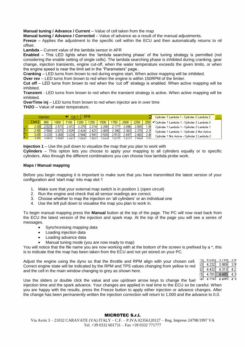
Manual tuning / Advance / Current – Value of cell taken from the map Manual tuning / Advance / Corrected – Value of advance as a result of the manual adjustments. Freeze – Applies the adjustment to the specific cell within the ECU and then automatically returns to nil offset. Lambda – Current value of the lambda sensor in AFR Enabled – This LED lights when the „lambda searching phase‟ of the tuning strategy is permitted (not considering the enable setting of single cells). The lambda searching phase is inhibited during cranking, gear change, injection transients, engine cut-off, when the water temperature exceeds the given limits, or when the engine speed is near the limit set in the “Parameters” page.. Cranking – LED turns from brown to red during engine start. When active mapping will be inhibited. Over rev – LED turns from brown to red when the engine is within 150RPM of the limiter. Cut off – LED turns from brown to red when the „cut off‟ strategy is enabled. When active mapping will be inhibited. Transient - LED turns from brown to red when the transient strategy is active. When active mapping will be inhibited. OverTime inj – LED turns from brown to red when injector are in over time TH2O – Value of water temperature.
Injection 1 – Use the pull down to visualize the map that you plan to work with Cylinders – This option lets you choose to apply your mapping to all cylinders equally or to specific cylinders. Also through the different combinations you can choose how lambda probe work. Maps / Manual mapping Before you begin mapping it is important to make sure that you have transmitted the latest version of your configuration and „start map‟ into map slot 1
1. Make sure that your external map switch is in position 1 (open circuit) 2. Run the engine and check that all sensor readings are correct. 3. Choose whether to map the injection on „all cylinders‟ or an individual one 4. Use the left pull down to visualise the map you plan to work in.
To begin manual mapping press the Manual button at the top of the page. The PC will now read back from the ECU the latest version of the injection and spark map. At the top of the page you will see a series of messages.
Synchronising mapping data
Loading injection data
Loading advance data
Manual tuning mode (you are now ready to map) You will notice that the file name you are now working with at the bottom of the screen is prefixed by a *, this is to indicate that the map has been taken from the ECU and not yet stored on your PC. Adjust the engine using the dyno so that the throttle and RPM align with your chosen cell. Correct engine state will be indicated by the RPM and TPS values changing from yellow to red and the cell in the main window changing to grey as shown here. Use the sliders or double click the value and use up/down arrow keys to change the fuel injection time and the spark advance. Your changes are applied in real time to the ECU so be careful. When you are happy with the results, press the Freeze button to apply either injection or advance changes. After the change has been permanently written the injection correction will return to 1.000 and the advance to 0.0.
MICROTEC S.r.l.
Via Avris 3 – 21032 CARAVATE (VA) ITALY – C.F. – P.IVA 02356120127 – Reg. Imprese 24798/1997 VA
Tel. +39 0332 601731 – Fax +39 0332 771777
The Current and corrected windows give a real time readout of the existing ECU setting and the new setting, after the new settings have been written, both will be the same and the cell in the main window will be updated and showing in bold red to indicate that a change has been made Now move onto the next cell you wish to work on. When all mapping work is done use the OFF button at top right. All of the modified cells are showing in bold red, including the ones in other pages. If you want to make some manual changes at this stage you will need to exit the Map tuning page and use the Map edit page, this is easily done by pressing the Map button at the bottom of the page, the red bold cells are still showing and you are free to make manual changes. This file must now be saved, use the Save button, choose Mapping and remember to remove the * prefix or you will not be allowed to save the file.
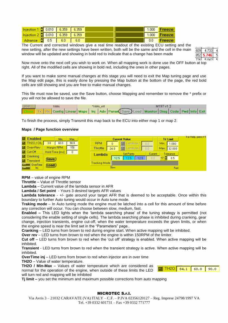
To finish the process, simply Transmit this map back to the ECU into either map 1 or map 2. Maps / Page function overview
RPM – value of engine RPM Throttle – Value of Throttle sensor Lambda – Current value of the lambda sensor in AFR Lambda / Set point - Yours 3 desired targets AFR values Lambda tolerance - +/- gate around your target AFR that is deemed to be acceptable. Once within this boundary to further Auto tuning would occur in Auto tune mode. Traking mode – In Auto tuning mode the engine must be latched into a cell for this amount of time before any correction will occur. You can choose between slow, medium, fast. Enabled – This LED lights when the „lambda searching phase‟ of the tuning strategy is permitted (not considering the enable setting of single cells). The lambda searching phase is inhibited during cranking, gear change, injection transients, engine cut-off, when the water temperature exceeds the given limits, or when the engine speed is near the limit set in the “Parameters” page.. Cranking – LED turns from brown to red during engine start. When active mapping will be inhibited. Over rev – LED turns from brown to red when the engine is within 150RPM of the limiter. Cut off – LED turns from brown to red when the „cut off‟ strategy is enabled. When active mapping will be inhibited. Transient - LED turns from brown to red when the transient strategy is active. When active mapping will be inhibited. OverTime inj – LED turns from brown to red when injector are in over time TH2O – Value of water temperature. TH2O / Min-Max – Values of water temperature which are considered as normal for the operation of the engine, when outside of these limits the LED will turn red and mapping will be inhibited Tj limit – you set the minimum and maximum possible corrections from auto mapping
MICROTEC S.r.l.
Via Avris 3 – 21032 CARAVATE (VA) ITALY – C.F. – P.IVA 02356120127 – Reg. Imprese 24798/1997 VA
Tel. +39 0332 601731 – Fax +39 0332 771777
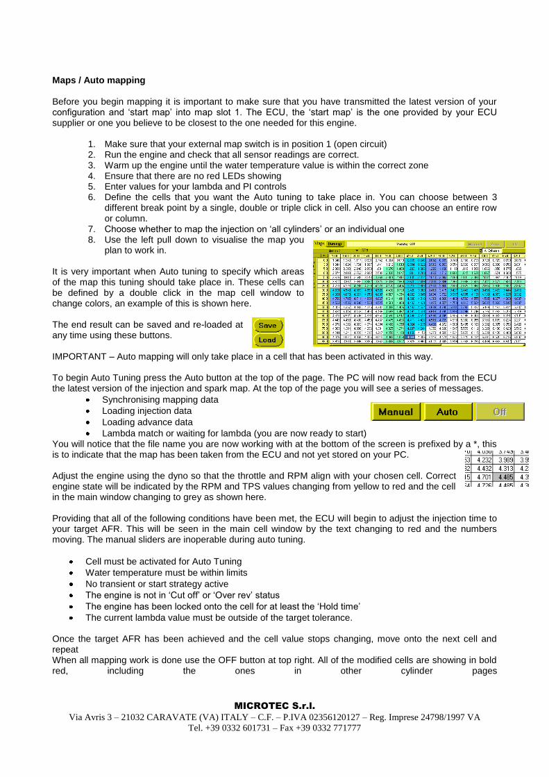
Maps / Auto mapping Before you begin mapping it is important to make sure that you have transmitted the latest version of your configuration and „start map‟ into map slot 1. The ECU, the „start map‟ is the one provided by your ECU supplier or one you believe to be closest to the one needed for this engine.
1. Make sure that your external map switch is in position 1 (open circuit) 2. Run the engine and check that all sensor readings are correct. 3. Warm up the engine until the water temperature value is within the correct zone 4. Ensure that there are no red LEDs showing 5. Enter values for your lambda and PI controls 6. Define the cells that you want the Auto tuning to take place in. You can choose between 3
different break point by a single, double or triple click in cell. Also you can choose an entire row or column.
7. Choose whether to map the injection on „all cylinders‟ or an individual one 8. Use the left pull down to visualise the map you
plan to work in. It is very important when Auto tuning to specify which areas of the map this tuning should take place in. These cells can be defined by a double click in the map cell window to change colors, an example of this is shown here. The end result can be saved and re-loaded at any time using these buttons. IMPORTANT – Auto mapping will only take place in a cell that has been activated in this way.
To begin Auto Tuning press the Auto button at the top of the page. The PC will now read back from the ECU the latest version of the injection and spark map. At the top of the page you will see a series of messages.
Synchronising mapping data
Loading injection data
Loading advance data
Lambda match or waiting for lambda (you are now ready to start) You will notice that the file name you are now working with at the bottom of the screen is prefixed by a *, this is to indicate that the map has been taken from the ECU and not yet stored on your PC. Adjust the engine using the dyno so that the throttle and RPM align with your chosen cell. Correct engine state will be indicated by the RPM and TPS values changing from yellow to red and the cell in the main window changing to grey as shown here. Providing that all of the following conditions have been met, the ECU will begin to adjust the injection time to your target AFR. This will be seen in the main cell window by the text changing to red and the numbers moving. The manual sliders are inoperable during auto tuning.
Cell must be activated for Auto Tuning
Water temperature must be within limits
No transient or start strategy active
The engine is not in „Cut off‟ or „Over rev‟ status
The engine has been locked onto the cell for at least the „Hold time‟
The current lambda value must be outside of the target tolerance. Once the target AFR has been achieved and the cell value stops changing, move onto the next cell and repeat When all mapping work is done use the OFF button at top right. All of the modified cells are showing in bold red, including the ones in other cylinder pages
MICROTEC S.r.l.
Via Avris 3 – 21032 CARAVATE (VA) ITALY – C.F. – P.IVA 02356120127 – Reg. Imprese 24798/1997 VA
Tel. +39 0332 601731 – Fax +39 0332 771777
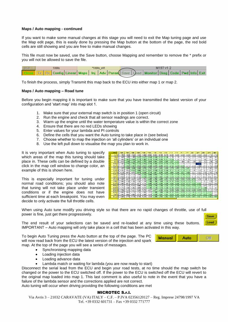
Maps / Auto mapping - continued If you want to make some manual changes at this stage you will need to exit the Map tuning page and use the Map edit page, this is easily done by pressing the Map button at the bottom of the page, the red bold cells are still showing and you are free to make manual changes. This file must now be saved, use the Save button, choose Mapping and remember to remove the * prefix or you will not be allowed to save the file.
To finish the process, simply Transmit this map back to the ECU into either map 1 or map 2. Maps / Auto mapping – Road tune Before you begin mapping it is important to make sure that you have transmitted the latest version of your configuration and „start map‟ into map slot 1.
1. Make sure that your external map switch is in position 1 (open circuit) 2. Run the engine and check that all sensor readings are correct. 3. Warm up the engine until the water temperature value is within the correct zone 4. Ensure that there are no red LEDs showing 5. Enter values for your lambda and PI controls 6. Define the cells that you want the Auto tuning to take place in (see below) 7. Choose whether to map the injection on „all cylinders‟ or an individual one 8. Use the left pull down to visualise the map you plan to work in.
It is very important when Auto tuning to specify which areas of the map this tuning should take place in. These cells can be defined by a double click in the map cell window to change color, an example of this is shown here. This is especially important for tuning under normal road conditions; you should also note that tuning will not take place under transient conditions or if the engine does not have sufficient time at each breakpoint. You may even decide to only activate the full throttle cells. When using Auto tune modify you driving style so that there are no rapid changes of throttle, use of full power is fine, just get there progressively. The end result of your selections can be saved and re-loaded at any time using these buttons. IMPORTANT – Auto mapping will only take place in a cell that has been activated in this way.
To begin Auto Tuning press the Auto button at the top of the page. The PC will now read back from the ECU the latest version of the injection and spark map. At the top of the page you will see a series of messages.
Synchronising mapping data
Loading injection data
Loading advance data
Lambda match or waiting for lambda (you are now ready to start) Disconnect the serial lead from the ECU and begin your road tests, at no time should the map switch be changed or the power to the ECU switched off. If the power to the ECU is switched off the ECU will revert to the original map loaded into map 1. This last comment is also useful to note in the event that you have a failure of the lambda sensor and the corrections applied are not correct. Auto tuning will occur when driving providing the following conditions are met
MICROTEC S.r.l.
Via Avris 3 – 21032 CARAVATE (VA) ITALY – C.F. – P.IVA 02356120127 – Reg. Imprese 24798/1997 VA
Tel. +39 0332 601731 – Fax +39 0332 771777
Cell must be activated for Auto Tuning
Water temperature must be within limits
No transient strategy active
The engine is not in „Cut off‟ or „Over rev‟ status
The engine has been locked onto the cell for at least the „Hold time‟
The current lambda value must be outside of the target tolerance. It should be noted that all of the changes are not being written to the original maps 1 or 2, the After the road test the ECU should be re-connected to the PC, at this point there are 2 possibilities:
ECU has been switched off/on during the test
ECU has remained switched on since it was disconnected from the PC.
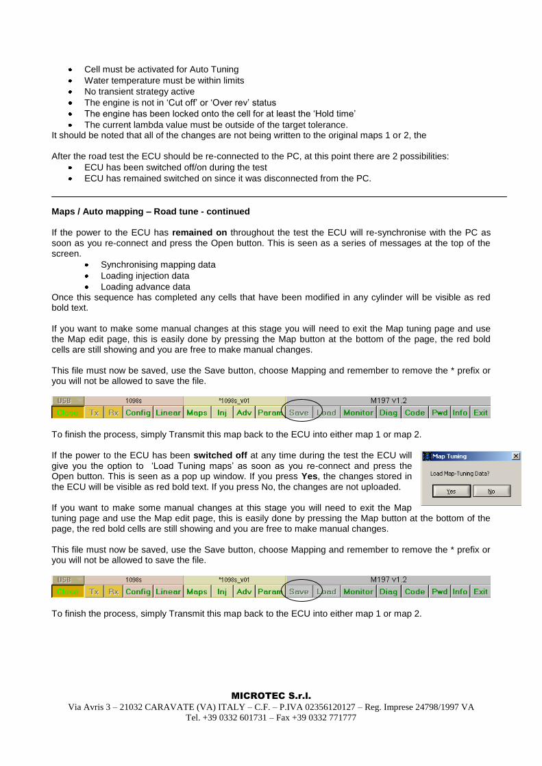
Maps / Auto mapping – Road tune - continued If the power to the ECU has remained on throughout the test the ECU will re-synchronise with the PC as soon as you re-connect and press the Open button. This is seen as a series of messages at the top of the screen.
Synchronising mapping data
Loading injection data
Loading advance data Once this sequence has completed any cells that have been modified in any cylinder will be visible as red bold text. If you want to make some manual changes at this stage you will need to exit the Map tuning page and use the Map edit page, this is easily done by pressing the Map button at the bottom of the page, the red bold cells are still showing and you are free to make manual changes. This file must now be saved, use the Save button, choose Mapping and remember to remove the * prefix or you will not be allowed to save the file.
To finish the process, simply Transmit this map back to the ECU into either map 1 or map 2. If the power to the ECU has been switched off at any time during the test the ECU will give you the option to „Load Tuning maps‟ as soon as you re-connect and press the Open button. This is seen as a pop up window. If you press Yes, the changes stored in the ECU will be visible as red bold text. If you press No, the changes are not uploaded. If you want to make some manual changes at this stage you will need to exit the Map tuning page and use the Map edit page, this is easily done by pressing the Map button at the bottom of the page, the red bold cells are still showing and you are free to make manual changes. This file must now be saved, use the Save button, choose Mapping and remember to remove the * prefix or you will not be allowed to save the file.
To finish the process, simply Transmit this map back to the ECU into either map 1 or map 2.
MICROTEC S.r.l.
Via Avris 3 – 21032 CARAVATE (VA) ITALY – C.F. – P.IVA 02356120127 – Reg. Imprese 24798/1997 VA
Tel. +39 0332 601731 – Fax +39 0332 771777
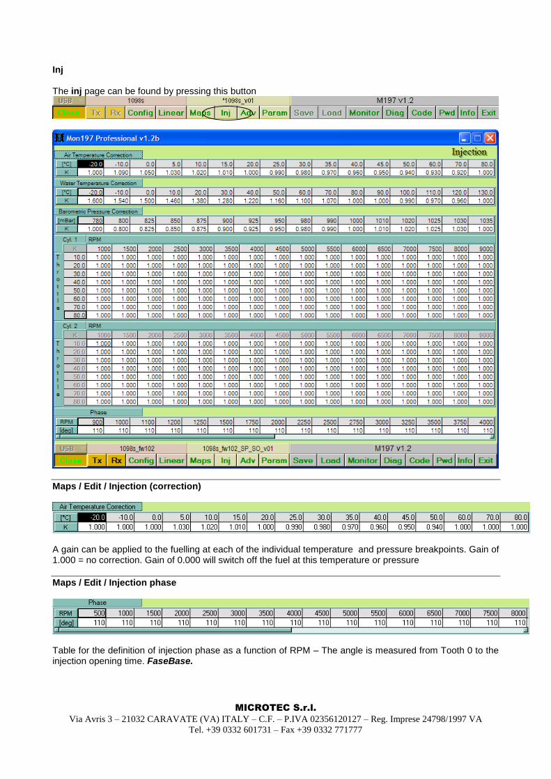
Inj The inj page can be found by pressing this button
Maps / Edit / Injection (correction)
A gain can be applied to the fuelling at each of the individual temperature and pressure breakpoints. Gain of 1.000 = no correction. Gain of 0.000 will switch off the fuel at this temperature or pressure
Maps / Edit / Injection phase
Table for the definition of injection phase as a function of RPM – The angle is measured from Tooth 0 to the injection opening time. FaseBase.
MICROTEC S.r.l.
Via Avris 3 – 21032 CARAVATE (VA) ITALY – C.F. – P.IVA 02356120127 – Reg. Imprese 24798/1997 VA
Tel. +39 0332 601731 – Fax +39 0332 771777
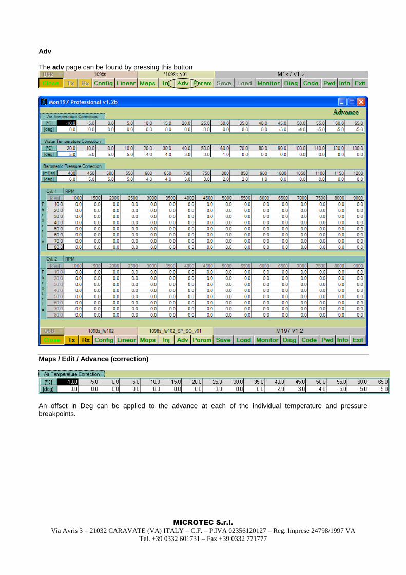
Adv The adv page can be found by pressing this button
Maps / Edit / Advance (correction)
An offset in Deg can be applied to the advance at each of the individual temperature and pressure breakpoints.
MICROTEC S.r.l.
Via Avris 3 – 21032 CARAVATE (VA) ITALY – C.F. – P.IVA 02356120127 – Reg. Imprese 24798/1997 VA
Tel. +39 0332 601731 – Fax +39 0332 771777
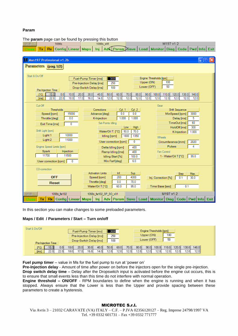
Param The param page can be found by pressing this button
In this section you can make changes to some preloaded parameters. Maps / Edit / Parameters / Start – Turn on/off
Fuel pump timer – value in Ms for the fuel pump to run at „power on‟ Pre-Injection delay - Amount of time after power on before the injectors open for the single pre-injection. Drop switch delay time – Delay after the Dropswitch input is activated before the engine cut occurs, this is to ensure that small events less than this time do not interfere with normal operation. Engine threshold – ON/OFF - RPM boundaries to define when the engine is running and when it has stopped. Always ensure that the Lower is less than the Upper and provide spacing between these parameters to create a hysteresis.
MICROTEC S.r.l.
Via Avris 3 – 21032 CARAVATE (VA) ITALY – C.F. – P.IVA 02356120127 – Reg. Imprese 24798/1997 VA
Tel. +39 0332 601731 – Fax +39 0332 771777
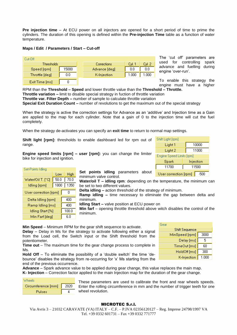
Pre injection time – At ECU power on all injectors are opened for a short period of time to prime the cylinders. The duration of this opening is defined within the Pre-injection Time table as a function of water temperature. Maps / Edit / Parameters / Start – Cut-off
The „cut off‟ parameters are used for controlling spark advance and fuelling during engine „over-run‟. To enable this strategy the engine must have a higher
RPM than the Threshold – Speed and lower throttle value than the Threshold – Throttle. Throttle variation – limit to disable special strategy in fuction of throttle variation Throttle var. Filter Depth – number of sample to calculate throttle variation Special Exit Duration Count – number of revolutions to get the maximum out of the special strategy When the strategy is active the correction settings for Advance as an „additive‟ and Injection time as a Gain are applied to the map for each cylinder. Note that a gain of 0 to the injection time will cut the fuel completely. When the strategy de-activates you can specify an exit time to return to normal map settings. Shift light [rpm]: thresholds to enable dashboard led for rpm out of range. Engine speed limits [rpm] – user [rpm]: you can change the limiter bike for injection and ignition.
Set points idling parameters about minimum valve control. Water/oil T – idling rpm: depending on the temperature, the minimum can be set to two different values. Delta idling – action threshold of the strategy of minimum. Ramp idling – time necessary to eliminate the gap between delta and minimum. Idling Start – valve position at ECU power on Min farf – opening throttle threshold above witch disables the control of the minimum.
Min Speed – Minimum RPM for the gear shift sequence to activate. Delay – Delay in Ms for the strategy to activate following either a signal from the Load cell, the Switch input or the Shift threshold from the potentiometer. Time out – The maximum time for the gear change process to complete in Ms. Hold Off – To eliminate the possibility of a „double switch‟ the time „de-bounce‟ disables the strategy from re-occurring for „x‟ Ms starting from the end of the previous occurrence. Advance – Spark advance value to be applied during gear change, this value replaces the main map. K- Injection – Correction factor applied to the main Injection map for the duration of the gear change.
These parameters are used to calibrate the front and rear wheels speeds. Enter the rolling circumference in mm and the number of trigger teeth for one wheel revolution.
MICROTEC S.r.l.
Via Avris 3 – 21032 CARAVATE (VA) ITALY – C.F. – P.IVA 02356120127 – Reg. Imprese 24798/1997 VA
Tel. +39 0332 601731 – Fax +39 0332 771777
Remember that this needs to be correct if you are planning to use wheel speed within your map corrections. CO correction
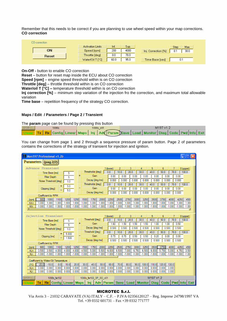
On-Off - button to enable CO correction Reset – button for reset map inside the ECU about CO correction Speed [rpm] – engine speed threshold within is on CO correction Throttle [deg] – throttle threshold within is on CO correction Water/oil T [°C] – temperature threshold within is on CO correction Inj correction [%] – minimum step variation of the injection fro the correction, and maximum total allowable variation Time base – repetition frequency of the strategy CO correction. Maps / Edit / Parameters / Page 2 / Transient The param page can be found by pressing this button
You can change from page 1 and 2 through a sequence pressure of param button. Page 2 of parameters contains the corrections of the strategy of transient for injection and ignition.
MICROTEC S.r.l.
Via Avris 3 – 21032 CARAVATE (VA) ITALY – C.F. – P.IVA 02356120127 – Reg. Imprese 24798/1997 VA
Tel. +39 0332 601731 – Fax +39 0332 771777
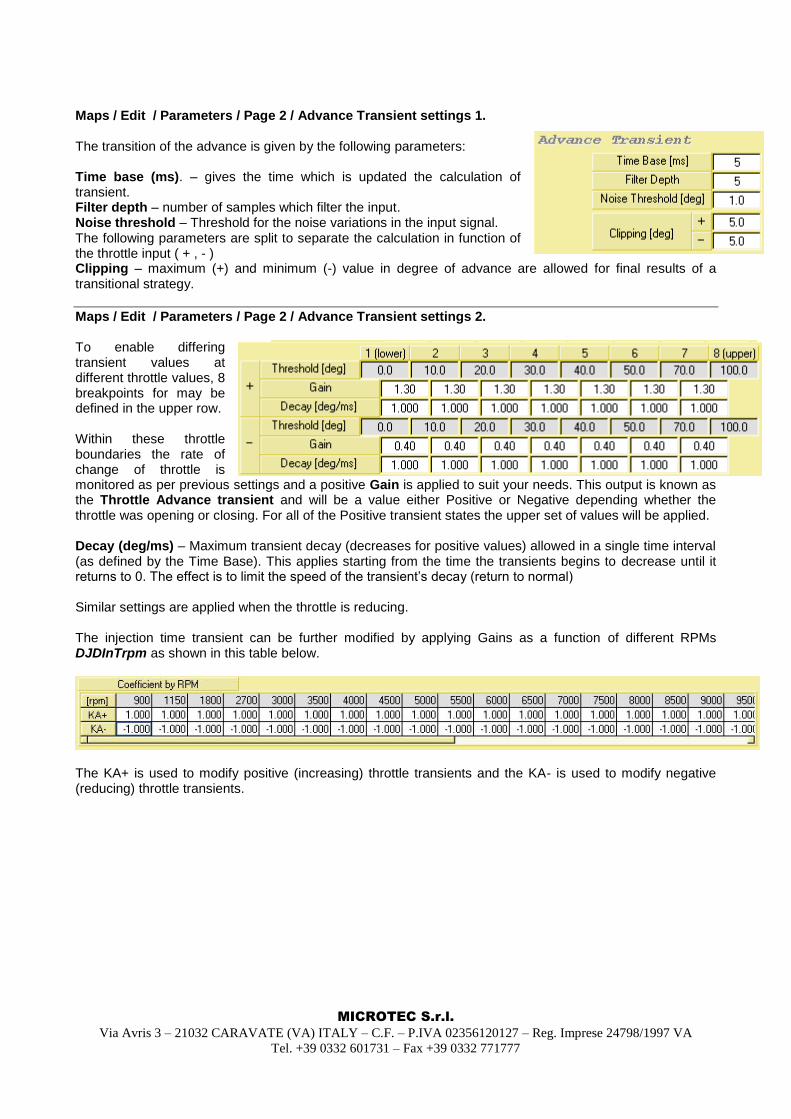
Maps / Edit / Parameters / Page 2 / Advance Transient settings 1. The transition of the advance is given by the following parameters: Time base (ms). – gives the time which is updated the calculation of transient. Filter depth – number of samples which filter the input. Noise threshold – Threshold for the noise variations in the input signal. The following parameters are split to separate the calculation in function of the throttle input ( + , - ) Clipping – maximum (+) and minimum (-) value in degree of advance are allowed for final results of a transitional strategy.
Maps / Edit / Parameters / Page 2 / Advance Transient settings 2. To enable differing transient values at different throttle values, 8 breakpoints for may be defined in the upper row. Within these throttle boundaries the rate of change of throttle is monitored as per previous settings and a positive Gain is applied to suit your needs. This output is known as the Throttle Advance transient and will be a value either Positive or Negative depending whether the throttle was opening or closing. For all of the Positive transient states the upper set of values will be applied. Decay (deg/ms) – Maximum transient decay (decreases for positive values) allowed in a single time interval (as defined by the Time Base). This applies starting from the time the transients begins to decrease until it returns to 0. The effect is to limit the speed of the transient‟s decay (return to normal) Similar settings are applied when the throttle is reducing. The injection time transient can be further modified by applying Gains as a function of different RPMs DJDInTrpm as shown in this table below.
The KA+ is used to modify positive (increasing) throttle transients and the KA- is used to modify negative (reducing) throttle transients.
MICROTEC S.r.l.
Via Avris 3 – 21032 CARAVATE (VA) ITALY – C.F. – P.IVA 02356120127 – Reg. Imprese 24798/1997 VA
Tel. +39 0332 601731 – Fax +39 0332 771777
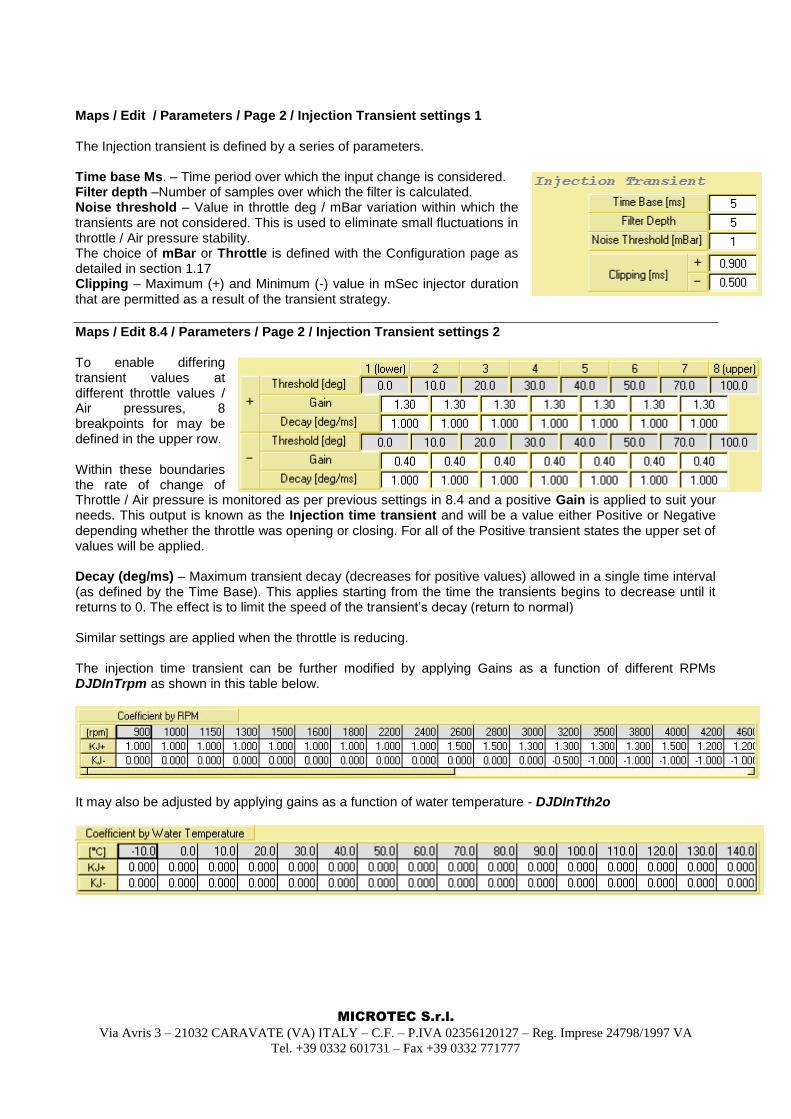
Maps / Edit / Parameters / Page 2 / Injection Transient settings 1 The Injection transient is defined by a series of parameters. Time base Ms. – Time period over which the input change is considered. Filter depth –Number of samples over which the filter is calculated. Noise threshold – Value in throttle deg / mBar variation within which the transients are not considered. This is used to eliminate small fluctuations in throttle / Air pressure stability. The choice of mBar or Throttle is defined with the Configuration page as detailed in section 1.17 Clipping – Maximum (+) and Minimum (-) value in mSec injector duration that are permitted as a result of the transient strategy.
Maps / Edit 8.4 / Parameters / Page 2 / Injection Transient settings 2 To enable differing transient values at different throttle values / Air pressures, 8 breakpoints for may be defined in the upper row. Within these boundaries the rate of change of Throttle / Air pressure is monitored as per previous settings in 8.4 and a positive Gain is applied to suit your needs. This output is known as the Injection time transient and will be a value either Positive or Negative depending whether the throttle was opening or closing. For all of the Positive transient states the upper set of values will be applied. Decay (deg/ms) – Maximum transient decay (decreases for positive values) allowed in a single time interval (as defined by the Time Base). This applies starting from the time the transients begins to decrease until it returns to 0. The effect is to limit the speed of the transient‟s decay (return to normal) Similar settings are applied when the throttle is reducing. The injection time transient can be further modified by applying Gains as a function of different RPMs DJDInTrpm as shown in this table below.
It may also be adjusted by applying gains as a function of water temperature - DJDInTth2o
MICROTEC S.r.l.
Via Avris 3 – 21032 CARAVATE (VA) ITALY – C.F. – P.IVA 02356120127 – Reg. Imprese 24798/1997 VA
Tel. +39 0332 601731 – Fax +39 0332 771777
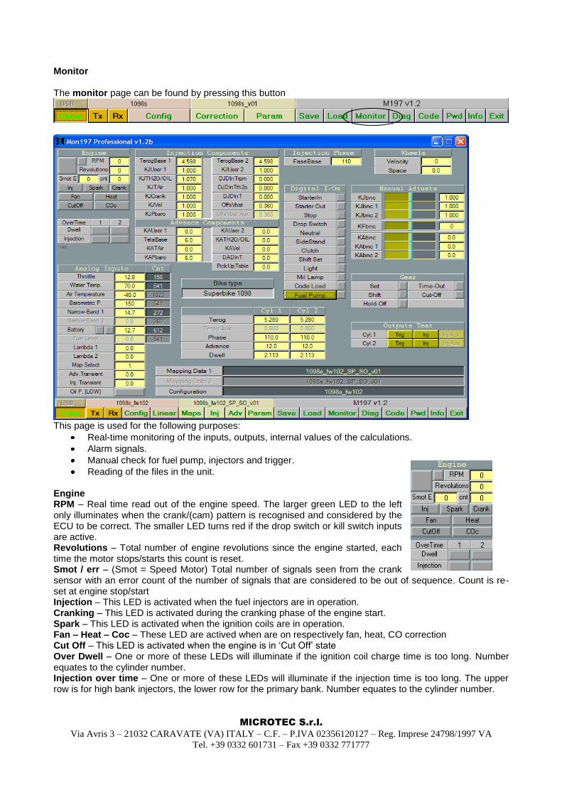
Monitor The monitor page can be found by pressing this button
This page is used for the following purposes:
Real-time monitoring of the inputs, outputs, internal values of the calculations.
Alarm signals.
Manual check for fuel pump, injectors and trigger.
Reading of the files in the unit. Engine RPM – Real time read out of the engine speed. The larger green LED to the left only illuminates when the crank/(cam) pattern is recognised and considered by the ECU to be correct. The smaller LED turns red if the drop switch or kill switch inputs are active. Revolutions – Total number of engine revolutions since the engine started, each time the motor stops/starts this count is reset. Smot / err – (Smot = Speed Motor) Total number of signals seen from the crank sensor with an error count of the number of signals that are considered to be out of sequence. Count is re-set at engine stop/start Injection – This LED is activated when the fuel injectors are in operation. Cranking – This LED is activated during the cranking phase of the engine start. Spark – This LED is activated when the ignition coils are in operation. Fan – Heat – Coc – These LED are actived when are on respectively fan, heat, CO correction Cut Off – This LED is activated when the engine is in „Cut Off‟ state Over Dwell – One or more of these LEDs will illuminate if the ignition coil charge time is too long. Number equates to the cylinder number. Injection over time – One or more of these LEDs will illuminate if the injection time is too long. The upper row is for high bank injectors, the lower row for the primary bank. Number equates to the cylinder number.
MICROTEC S.r.l.
Via Avris 3 – 21032 CARAVATE (VA) ITALY – C.F. – P.IVA 02356120127 – Reg. Imprese 24798/1997 VA
Tel. +39 0332 601731 – Fax +39 0332 771777
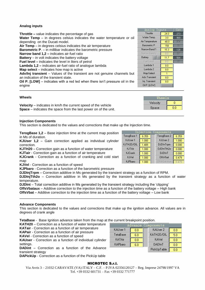
Analog inputs Throttle – value indicates the percentage of gas Water Temp – in degrees celsius indicates the water temperature or oil depending on the Ducati model. Air Temp – in degrees celsius indicates the air temperature Barometric P. – in millibar indicates the barometric pressure Narrow band 1,2 – indicates air-fuel ratio Battery – in volt indicates the battery voltage Fuel level – indicates the level in liters of petrol Lambda 1,2 – indicates air-fuel ratio of analogue lambda Map select – indicates how map is active Adv/Inj transient – Values of the transient are not genuine channels but an indication of the transient state. Oil P. [LOW] – indicates with a red led when there isn‟t pressure oil in the engine Wheels Velocity – indicates in km/h the current speed of the vehicle Space – indicates the space from the last power on of the unit. Injection Components This section is dedicated to the values and corrections that make up the Injection time. TerogBase 1,2 – Base injection time at the current map position in Ms of duration. KJUser 1,2 – Gain correction applied as individual cylinder correction. KJTH20 – Correction gain as a function of water temperature KJTair - Correction gain as a function of air temperature KJCrank - Correction as a function of cranking and cold start map KJVel - Correction as a function of speed KJPbaro - Correction as a function of the barometric pressure DJDInjTrpm – Correction additive in Ms generated by the transient strategy as a function of RPM. DJDInjTth2o – Correction additive in Ms generated by the transient strategy as a function of water temperature. DJDInt – Total correction additive in Ms generated by the transient strategy including the „clipping‟ OffsVbataux – Additive correction to the injection time as a function of the battery voltage – High bank OffsVbat – Additive correction to the injection time as a function of the battery voltage – Low bank Advance Components This section is dedicated to the values and corrections that make up the ignition advance. All values are in degrees of crank angle TetaBase - Base Ignition advance taken from the map at the current breakpoint position. KATH20 – Correction as a function of water temperature KATair - Correction as a function of air temperature KAPair - Correction as a function of air pressure KAVel - Correction as a function of speed KAUser - Correction as a function of individual cylinder settings. DADint – Correction as a function of the Advance transient strategy DAPickUp - Correction as a function of the PickUp table
MICROTEC S.r.l.
Via Avris 3 – 21032 CARAVATE (VA) ITALY – C.F. – P.IVA 02356120127 – Reg. Imprese 24798/1997 VA
Tel. +39 0332 601731 – Fax +39 0332 771777
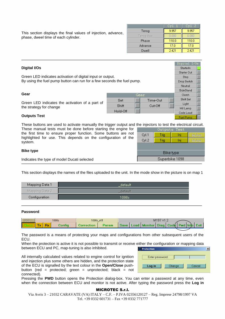
This section displays the final values of injection, advance, phase, dweel time of each cylinder. Digital I/Os Green LED indicates activation of digital input or output. By using the fuel pump button can run for a few seconds the fuel pump. Gear Green LED indicates the activation of a part of the strategy for change Outputs Test These buttons are used to activate manually the trigger output and the injectors to test the electrical circuit. These manual tests must be done before starting the engine for the first time to ensure proper function. Some buttons are not highlighted for use. This depends on the configuration of the system. Bike type Indicates the type of model Ducati selected This section displays the names of the files uploaded to the unit. In the mode show in the picture is on map 1
Password
The password is a means of protecting your maps and configurations from other subsequent users of the ECU. When the protection is active it is not possible to transmit or receive either the configuration or mapping data between ECU and PC, map-tuning is also inhibited. All internally calculated values related to engine control for ignition and injection plus some others are hidden, and the protection state of the ECU is signalled by the text colour in the Open/Close push-button (red = protected; green = unprotected; black = not connected). Pressing the PWD button opens the Protection dialog-box. You can enter a password at any time, even when the connection between ECU and monitor is not active. After typing the password press the Log in
MICROTEC S.r.l.
Via Avris 3 – 21032 CARAVATE (VA) ITALY – C.F. – P.IVA 02356120127 – Reg. Imprese 24798/1997 VA
Tel. +39 0332 601731 – Fax +39 0332 771777
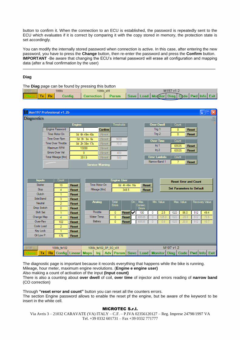
button to confirm it. When the connection to an ECU is established, the password is repeatedly sent to the ECU which evaluates if it is correct by comparing it with the copy stored in memory, the protection state is set accordingly. You can modify the internally stored password when connection is active. In this case, after entering the new password, you have to press the Change button, then re-enter the password and press the Confirm button. IMPORTANT -Be aware that changing the ECU‟s internal password will erase all configuration and mapping data (after a final confirmation by the user) Diag The Diag page can be found by pressing this button
The diagnostic page is important because it records everything that happens while the bike is running. Mileage, hour meter, maximum engine revolutions. (Engine e engine user) Also making a count of activation of the input (Input count) There is also a counting about over dwell of coil, over time of injector and errors reading of narrow band (CO correction) Through “reset error and count” button you can reset all the counters errors. The section Engine password allows to enable the reset pf the engine, but be aware of the keyword to be insert in the white cell.
MICROTEC S.r.l.
Via Avris 3 – 21032 CARAVATE (VA) ITALY – C.F. – P.IVA 02356120127 – Reg. Imprese 24798/1997 VA
Tel. +39 0332 601731 – Fax +39 0332 771777
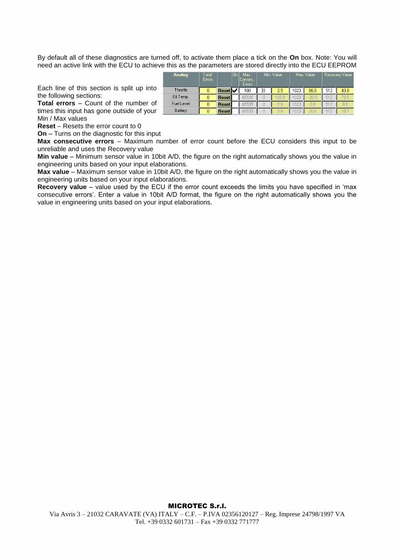
By default all of these diagnostics are turned off, to activate them place a tick on the On box. Note: You will need an active link with the ECU to achieve this as the parameters are stored directly into the ECU EEPROM Each line of this section is split up into the following sections: Total errors – Count of the number of times this input has gone outside of your Min / Max values Reset – Resets the error count to 0 On – Turns on the diagnostic for this input Max consecutive errors – Maximum number of error count before the ECU considers this input to be unreliable and uses the Recovery value Min value – Minimum sensor value in 10bit A/D, the figure on the right automatically shows you the value in engineering units based on your input elaborations. Max value – Maximum sensor value in 10bit A/D, the figure on the right automatically shows you the value in engineering units based on your input elaborations. Recovery value – value used by the ECU if the error count exceeds the limits you have specified in „max consecutive errors‟. Enter a value in 10bit A/D format, the figure on the right automatically shows you the value in engineering units based on your input elaborations.
MICROTEC S.r.l.
Via Avris 3 – 21032 CARAVATE (VA) ITALY – C.F. – P.IVA 02356120127 – Reg. Imprese 24798/1997 VA
Tel. +39 0332 601731 – Fax +39 0332 771777
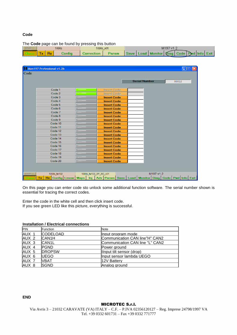
Code The Code page can be found by pressing this button
On this page you can enter code sto unlock some additional function software. The serial number shown is essential for tracing the correct codes. Enter the code in the white cell and then click insert code. If you see green LED like this picture, everything is successful. Installation / Electrical connections
PIN Function Note
AUX_1 CODELOAD Input program mode AUX_2 CAN1H Communication CAN line"H" CAN2 AUX_3 CAN1L Communication CAN line "L" CAN2 AUX_4 PGND Power ground AUX_5 DROPSW IInput tilt sensor (drop) AUX_6 UEGO Input sensor lambda UEGO AUX_7 VBAT 12V Battery AUX_8 SGND Analog ground END