Embed Size (px)
Citation preview

MA299-024-00-00
Doc. ver.: 1.7
M16C v3.1
C Compiler,
Assembler, Linker
User's Manual
A publication of
Altium BV
Documentation Department
Copyright 2002-2005 Altium BV
All rights reserved. Reproduction in whole or part is prohibited
without the written consent of the copyright owner.
TASKING is a brand name of Altium Limited.
The following trademarks are acknowledged:
FLEXlm is a registered trademark of Macrovision Corporation.
Intel is a trademark of Intel Corporation.
Motorola is a registered trademark of Motorola, Inc.
MS-DOS and Windows are registered trademarks of Microsoft Corporation.
SUN is a trademark of Sun Microsystems, Inc.
UNIX is a registered trademark of X/Open Company, Ltd.
All other trademarks are property of their respective owners.
Data subject to alteration without notice.
http://www.tasking.com
http://www.altium.com

The information in this document has been carefully reviewed and isbelieved to be accurate and reliable. However, Altium assumes no liabilitiesfor inaccuracies in this document. Furthermore, the delivery of thisinformation does not convey to the recipient any license to use or copy thesoftware or documentation, except as provided in an executed licenseagreement covering the software and documentation.
Altium reserves the right to change specifications embodied in thisdocument without prior notice.

TABLE OF
CONTENTSC
ON
TE
NT
S

Table of ContentsIVCONTENTS
CO
NT
EN
TS

Table of Contents V
• • • • • • • •
SOFTWARE INSTALLATION AND CONFIGURATION 1-1
1.1 Introduction 1-3. . . . . . . . . . . . . . . . . . . . . . . . . . . . . . . . . . . .
1.2 Software Installation 1-3. . . . . . . . . . . . . . . . . . . . . . . . . . . . .
1.2.1 Installation for Windows 1-3. . . . . . . . . . . . . . . . . . . . . . . . . .
1.2.2 Installation for Linux 1-4. . . . . . . . . . . . . . . . . . . . . . . . . . . . .
1.2.3 Installation for UNIX Hosts 1-6. . . . . . . . . . . . . . . . . . . . . . .
1.3 Software Configuration 1-7. . . . . . . . . . . . . . . . . . . . . . . . . . .
1.3.1 Configuring the Embedded Development Environment 1-7
1.3.2 Configuring the Command Line Environment 1-9. . . . . . . .
1.4 Licensing TASKING Products 1-12. . . . . . . . . . . . . . . . . . . . . .
1.4.1 Obtaining License Information 1-12. . . . . . . . . . . . . . . . . . . .
1.4.2 Installing Node-Locked Licenses 1-13. . . . . . . . . . . . . . . . . . .
1.4.3 Installing Floating Licenses 1-14. . . . . . . . . . . . . . . . . . . . . . . .
1.4.4 Modifying the License File Location 1-16. . . . . . . . . . . . . . . .
1.4.5 How to Determine the Host ID 1-17. . . . . . . . . . . . . . . . . . . .
1.4.6 How to Determine the Host Name 1-17. . . . . . . . . . . . . . . . .
GETTING STARTED 2-1
2.1 Introduction 2-3. . . . . . . . . . . . . . . . . . . . . . . . . . . . . . . . . . . .
2.2 Working With Projects in EDE 2-7. . . . . . . . . . . . . . . . . . . . .
2.3 Start EDE 2-8. . . . . . . . . . . . . . . . . . . . . . . . . . . . . . . . . . . . . . .
2.4 Using the Sample Projects 2-9. . . . . . . . . . . . . . . . . . . . . . . .
2.5 Create a New Project Space with a Project 2-10. . . . . . . . . .
2.6 Set Options for the Tools in the Toolchain 2-14. . . . . . . . . .
2.7 Build your Application 2-17. . . . . . . . . . . . . . . . . . . . . . . . . . .
2.8 How to Build Your Application on the Command Line 2-18
2.9 Debug getstart.elf 2-19. . . . . . . . . . . . . . . . . . . . . . . . . . . . . . .
C LANGUAGE 3-1
3.1 Introduction 3-3. . . . . . . . . . . . . . . . . . . . . . . . . . . . . . . . . . . .
3.2 Programming Strategies 3-4. . . . . . . . . . . . . . . . . . . . . . . . . .
3.2.1 Memory Spaces 3-4. . . . . . . . . . . . . . . . . . . . . . . . . . . . . . . . .
3.2.2 Bit Programming 3-6. . . . . . . . . . . . . . . . . . . . . . . . . . . . . . . .
Table of ContentsVICONTENTS
3.2.3 Floating-Point 3-7. . . . . . . . . . . . . . . . . . . . . . . . . . . . . . . . . .
3.2.4 General Optimization Tips 3-8. . . . . . . . . . . . . . . . . . . . . . . .
3.3 Data Types 3-10. . . . . . . . . . . . . . . . . . . . . . . . . . . . . . . . . . . . .
3.4 Memory Qualifiers 3-12. . . . . . . . . . . . . . . . . . . . . . . . . . . . . . .
3.4.1 Memory Type Qualifiers 3-13. . . . . . . . . . . . . . . . . . . . . . . . . .
3.4.2 Accessing Peripherals from C: __sfr 3-15. . . . . . . . . . . . . . . .
3.4.3 Declare a Data Object at an Absolute Address: __at() 3-18.
3.5 Memory Models 3-19. . . . . . . . . . . . . . . . . . . . . . . . . . . . . . . . .
3.6 Using Assembly in the C Source: __asm() 3-20. . . . . . . . . . .
3.7 Controlling the Compiler: Pragmas 3-27. . . . . . . . . . . . . . . . .
3.8 Predefined Macros 3-28. . . . . . . . . . . . . . . . . . . . . . . . . . . . . . .
3.9 Initialized Variables 3-30. . . . . . . . . . . . . . . . . . . . . . . . . . . . . .
3.10 Strings 3-30. . . . . . . . . . . . . . . . . . . . . . . . . . . . . . . . . . . . . . . . .
3.11 Switch Statement 3-31. . . . . . . . . . . . . . . . . . . . . . . . . . . . . . . .
3.12 Functions 3-32. . . . . . . . . . . . . . . . . . . . . . . . . . . . . . . . . . . . . .
3.12.1 Parameter Passing 3-32. . . . . . . . . . . . . . . . . . . . . . . . . . . . . . .
3.12.2 Function Return Types 3-33. . . . . . . . . . . . . . . . . . . . . . . . . . .
3.12.3 Inlining Functions: inline 3-34. . . . . . . . . . . . . . . . . . . . . . . . .
3.12.4 Intrinsic Functions 3-36. . . . . . . . . . . . . . . . . . . . . . . . . . . . . . .
3.12.5 Calling Assembly Functions: __asmfunc 3-37. . . . . . . . . . . . .
3.12.6 Interrupt Functions 3-38. . . . . . . . . . . . . . . . . . . . . . . . . . . . . .
3.12.6.1 Defining an Interrupt Service Routine: __interrupt() 3-39. .
3.12.6.2 Register Bank Switching: __bankswitch 3-40. . . . . . . . . . . . .
3.12.6.3 Interrupt Frame: __frame() 3-41. . . . . . . . . . . . . . . . . . . . . . . .
3.13 Section Naming 3-42. . . . . . . . . . . . . . . . . . . . . . . . . . . . . . . . .
3.14 Libraries 3-44. . . . . . . . . . . . . . . . . . . . . . . . . . . . . . . . . . . . . . .
3.14.1 Overview of Libraries 3-44. . . . . . . . . . . . . . . . . . . . . . . . . . . .
3.14.2 Printf and Scanf Formatting Routines 3-45. . . . . . . . . . . . . . .
3.14.3 Rebuilding Libraries 3-46. . . . . . . . . . . . . . . . . . . . . . . . . . . . . .
3.15 Converting C Modules to ISO C99 3-47. . . . . . . . . . . . . . . . .

Table of Contents VII
• • • • • • • •
ASSEMBLY LANGUAGE 4-1
4.1 Introduction 4-3. . . . . . . . . . . . . . . . . . . . . . . . . . . . . . . . . . . .
4.2 Assembly Syntax 4-3. . . . . . . . . . . . . . . . . . . . . . . . . . . . . . . .
4.3 Assembler Significant Characters 4-4. . . . . . . . . . . . . . . . . . .
4.4 Operands of an Assembly Instruction 4-5. . . . . . . . . . . . . . .
4.5 Symbol Names 4-6. . . . . . . . . . . . . . . . . . . . . . . . . . . . . . . . . .
4.6 Assembly Expressions 4-7. . . . . . . . . . . . . . . . . . . . . . . . . . . .
4.6.1 Numeric Constants 4-8. . . . . . . . . . . . . . . . . . . . . . . . . . . . . .
4.6.2 Strings 4-8. . . . . . . . . . . . . . . . . . . . . . . . . . . . . . . . . . . . . . . . .
4.6.3 Expression Operators 4-9. . . . . . . . . . . . . . . . . . . . . . . . . . . .
4.7 Built-in Assembly Functions 4-11. . . . . . . . . . . . . . . . . . . . . .
4.8 Assembler Directives and Controls 4-13. . . . . . . . . . . . . . . . .
4.8.1 Overview of Assembler Directives 4-14. . . . . . . . . . . . . . . . .
4.8.2 Overview of Assembler Controls 4-16. . . . . . . . . . . . . . . . . . .
4.9 Working with Sections 4-17. . . . . . . . . . . . . . . . . . . . . . . . . . .
4.10 Macro Operations 4-19. . . . . . . . . . . . . . . . . . . . . . . . . . . . . . .
4.10.1 Defining a Macro 4-19. . . . . . . . . . . . . . . . . . . . . . . . . . . . . . . .
4.10.2 Calling a Macro 4-21. . . . . . . . . . . . . . . . . . . . . . . . . . . . . . . . .
4.10.3 Using Operators for Macro Arguments 4-22. . . . . . . . . . . . . .
4.10.4 Using the DUP, DUPA, DUPC, DUPF Directives as
Macros 4-26. . . . . . . . . . . . . . . . . . . . . . . . . . . . . . . . . . . . . . . . .
4.10.5 Conditional Assembly: IF, ELIF and ELSE Directives 4-26. . .
USING THE COMPILER 5-1
5.1 Introduction 5-3. . . . . . . . . . . . . . . . . . . . . . . . . . . . . . . . . . . .
5.2 Compilation Process 5-4. . . . . . . . . . . . . . . . . . . . . . . . . . . . .
5.3 Compiler Optimizations 5-5. . . . . . . . . . . . . . . . . . . . . . . . . .
5.3.1 Optimize for Size or Speed 5-9. . . . . . . . . . . . . . . . . . . . . . .
5.4 Calling the Compiler 5-10. . . . . . . . . . . . . . . . . . . . . . . . . . . . .
5.5 How the Compiler Searches Include Files 5-15. . . . . . . . . . .
5.6 Compiling for Debugging 5-15. . . . . . . . . . . . . . . . . . . . . . . . .
5.7 C Code Checking: MISRA-C 5-16. . . . . . . . . . . . . . . . . . . . . . .
5.8 C Compiler Diagnostics 5-19. . . . . . . . . . . . . . . . . . . . . . . . . .

Table of ContentsVIIICONTENTS
5.9 Run-Time Error Checking 5-21. . . . . . . . . . . . . . . . . . . . . . . .
5.9.1 Step 1: Build Your Application for Run-Time
Error Checking 5-24. . . . . . . . . . . . . . . . . . . . . . . . . . . . . . . . . .
5.9.2 Step 2: Execute the Application 5-25. . . . . . . . . . . . . . . . . . . .
5.9.3 Examples Producing Run-time Errors 5-25. . . . . . . . . . . . . .
PROFILING 6-1
6.1 What is profiling? 6-3. . . . . . . . . . . . . . . . . . . . . . . . . . . . . . . .
6.1.1 Three methods of profiling 6-4. . . . . . . . . . . . . . . . . . . . . . .
6.2 Profiling using Code Instrumentation 6-5. . . . . . . . . . . . . . .
6.2.1 Step 1: Build your Application for Profiling 6-7. . . . . . . . . .
6.2.1.1 Profiling Modules and Libraries 6-8. . . . . . . . . . . . . . . . . . . .
6.2.1.2 Linking Profiling Libraries 6-9. . . . . . . . . . . . . . . . . . . . . . . . .
6.2.2 Step 2: Execute the Application 6-9. . . . . . . . . . . . . . . . . . . .
6.2.3 Step 3: Displaying Profiling Results 6-11. . . . . . . . . . . . . . . . .
USING THE ASSEMBLER 7-1
7.1 Introduction 7-3. . . . . . . . . . . . . . . . . . . . . . . . . . . . . . . . . . . .
7.2 Assembly Process 7-3. . . . . . . . . . . . . . . . . . . . . . . . . . . . . . .
7.3 Assembler Optimizations 7-4. . . . . . . . . . . . . . . . . . . . . . . . .
7.4 Calling the Assembler 7-5. . . . . . . . . . . . . . . . . . . . . . . . . . . .
7.5 How the Assembler Searches Include Files 7-8. . . . . . . . . .
7.6 Generating a List File 7-8. . . . . . . . . . . . . . . . . . . . . . . . . . . .
7.7 Assembler Error Messages 7-9. . . . . . . . . . . . . . . . . . . . . . . .
USING THE LINKER 8-1
8.1 Introduction 8-3. . . . . . . . . . . . . . . . . . . . . . . . . . . . . . . . . . . .
8.2 Linking Process 8-4. . . . . . . . . . . . . . . . . . . . . . . . . . . . . . . . .
8.2.1 Phase 1: Linking 8-6. . . . . . . . . . . . . . . . . . . . . . . . . . . . . . . .
8.2.2 Phase 2: Locating 8-7. . . . . . . . . . . . . . . . . . . . . . . . . . . . . . . .
8.2.3 Linker Optimizations 8-9. . . . . . . . . . . . . . . . . . . . . . . . . . . . .
8.3 Calling the Linker 8-11. . . . . . . . . . . . . . . . . . . . . . . . . . . . . . .

Table of Contents IX
• • • • • • • •
8.4 Linking with Libraries 8-14. . . . . . . . . . . . . . . . . . . . . . . . . . . .
8.4.1 Specifying Libraries to the Linker 8-15. . . . . . . . . . . . . . . . . .
8.4.2 How the Linker Searches Libraries 8-16. . . . . . . . . . . . . . . . .
8.4.3 How the Linker Extracts Objects from Libraries 8-17. . . . . .
8.5 Incremental Linking 8-18. . . . . . . . . . . . . . . . . . . . . . . . . . . . .
8.6 Controlling the Linker with a Script 8-19. . . . . . . . . . . . . . . .
8.6.1 Purpose of the Linker Script Language 8-19. . . . . . . . . . . . . .
8.6.2 EDE and LSL 8-20. . . . . . . . . . . . . . . . . . . . . . . . . . . . . . . . . . . .
8.6.3 Structure of a Linker Script File 8-21. . . . . . . . . . . . . . . . . . . .
8.6.4 The Architecture Definition 8-24. . . . . . . . . . . . . . . . . . . . . . .
8.6.5 The Derivative Definition 8-26. . . . . . . . . . . . . . . . . . . . . . . . .
8.6.6 The Memory Definition 8-28. . . . . . . . . . . . . . . . . . . . . . . . . .
8.6.7 The Section Layout Definition: Locating Sections 8-30. . . . .
8.6.8 The Processor Definition: Using Multi-Processor
Systems 8-34. . . . . . . . . . . . . . . . . . . . . . . . . . . . . . . . . . . . . . . .
8.7 Linker Labels 8-35. . . . . . . . . . . . . . . . . . . . . . . . . . . . . . . . . . .
8.8 Generating a Map File 8-37. . . . . . . . . . . . . . . . . . . . . . . . . . . .
8.9 Linker Error Messages 8-38. . . . . . . . . . . . . . . . . . . . . . . . . . . .
USING THE UTILITIES 9-1
9.1 Introduction 9-3. . . . . . . . . . . . . . . . . . . . . . . . . . . . . . . . . . . .
9.2 Control Program 9-4. . . . . . . . . . . . . . . . . . . . . . . . . . . . . . . .
9.2.1 Calling the Control Program 9-4. . . . . . . . . . . . . . . . . . . . . . .
9.3 Make Utility 9-9. . . . . . . . . . . . . . . . . . . . . . . . . . . . . . . . . . . .
9.3.1 Calling the Make Utility 9-11. . . . . . . . . . . . . . . . . . . . . . . . . .
9.3.2 Writing a Makefile 9-12. . . . . . . . . . . . . . . . . . . . . . . . . . . . . . .
9.4 Archiver 9-23. . . . . . . . . . . . . . . . . . . . . . . . . . . . . . . . . . . . . . .
9.4.1 Calling the Archiver 9-23. . . . . . . . . . . . . . . . . . . . . . . . . . . . . .
9.4.2 Examples 9-25. . . . . . . . . . . . . . . . . . . . . . . . . . . . . . . . . . . . . .
9.5 Flash Utility 9-27. . . . . . . . . . . . . . . . . . . . . . . . . . . . . . . . . . . . .
9.5.1 Calling the Flash Utility 9-27. . . . . . . . . . . . . . . . . . . . . . . . . . .
INDEX

Table of ContentsXCONTENTS

Manual Purpose and Structure XI
• • • • • • • •
MANUAL PURPOSE AND STRUCTURE
The documentation explains and describes how to use the M16C toolchain
to program an M16C MCU.
Windows Users
You can use the tools either with the graphical Embedded Development
Environment (EDE) or from the command line in a command prompt
window.
Unix Users
For UNIX the toolchain works the same as it works for the Windows
command line.
Directory paths are specified in the Windows way, with back slashes as in
\cm16c\bin. Simply replace the back slashes by forward slashes for use
with UNIX: /cm16c/bin.
Structure
The toolchain documentation consists of a User's Manual (this manual)
which includes a Getting Started section and a separate Reference Manual.
First you need to install the software. This is described in Chapter 1,
Software Installation and Configuration
After installation you are ready to follow the Getting Started in Chapter 2.
Next, move on with the other chapters which explain how to use the
compiler, assembler, linker and the various utilities.
Once you are familiar with these tools, you can use the Reference Manual
to lookup specific options and details to make full use of the M16C
toolchain.

User's ManualXIIM
AN
UA
L S
TR
UC
TU
RE
SHORT TABLE OF CONTENTS
Chapter 1: Software Installation and Configuration
Guides you through the installation of the software. Describes the most
important settings, paths and filenames that you must specify to get the
package up and running.
Chapter 2: Getting Started
Overview of the toolchain and its individual elements. Describes the
relation between the toolchain and specific features of the M16C. Explains
step-by-step how to write, compile, assemble and debug your application.
Teaches how you can use projects to organize your files.
Chapter 3: C Language
The TASKING M16C C compiler is fully compatible with ISO-C. This
chapter describes the specific M16C features of the C language, including
language extensions that are not standard in ISO-C. For example, pragmas
are a way to control the compiler from within the C source.
Chapter 4: Assembly Language
Describes the specific features of the assembly language as well as
'directives', which are pseudo instructions that are interpreted by the
assembler.
Chapter 5: Using the Compiler
Describes how you can use the compiler. An extensive overview of all
options is included in the Reference Manual.
Chapter 6: Profiling
Profiling is a method of gathering data about the amount of time function
execution takes and how many times functions are called. This profiling
implementation is code instrumention based, which means that the
compiler adds extra code which gathers the requested data during
execution of the program. This chapter explains this profiling method into
detail.
Chapter 7: Using the Assembler
Describes how you can use the assembler. An extensive overview of all
options is included in the Reference Manual.

Manual Purpose and Structure XIII
• • • • • • • •
Chapter 8: Using the Linker
Describes how you can use the linker. An extensive overview of all
options is included in the Reference Manual.
Chapter 9: Using the Utilities
Describes several utilities and how you can use them to facilitate various
tasks. The following utilities are included: control program, make utility
and archiver.

User's ManualXIVM
AN
UA
L S
TR
UC
TU
RE
CONVENTIONS USED IN THIS MANUAL
Notation for syntax
The following notation is used to describe the syntax of command line
input:
bold Type this part of the syntax literally.
italics Substitute the italic word by an instance. For example:
filename
Type the name of a file in place of the word filename.
{ } Encloses a list from which you must choose an item.
[ ] Encloses items that are optional. For example
cm16c [ -? ]
Both cm16c and cm16c -? are valid commands.
| Separates items in a list. Read it as OR.
... You can repeat the preceding item zero or more times.
,... You can repeat the preceding item zero or more times,
separating each item with a comma.
Example
cm16c [option]... filename
You can read this line as follows: enter the command cm16c with or
without an option, follow this by zero or more options and specify a
filename. The following input lines are all valid:
cm16c test.c
cm16c -g test.c
cm16c -g -E test.c
Not valid is:
cm16c -g
According to the syntax description, you have to specify a filename.

Manual Purpose and Structure XV
• • • • • • • •
Icons
The following illustrations are used in this manual:
Note: notes give you extra information.
Warning: read the information carefully. It prevents you from making
serious mistakes or from loosing information.
This illustration indicates actions you can perform with the mouse. Such as
EDE menu entries and dialogs.
Command line: type your input on the command line.
Reference: follow this reference to find related topics.

User's ManualXVIM
AN
UA
L S
TR
UC
TU
RE
RELATED PUBLICATIONS
C Standards
• C A Reference Manual (fifth edition) by Samual P. Harbison and Guy L.
Steele Jr. (2002, Prentice Hall)
• The C Programming Language (second edition) by B. Kernighan and D.
Ritchie (1988, Prentice Hall)
• ISO/IEC 9899:1999(E), Programming languages - C [ISO/IEC]
See also http://www.ansi.org
• DSP-C, An Extension to ISO/IEC 9899:1999(E),
Programming languages - C [TASKING, TK0071-14]
MISRA C
• Guidelines for the Use of the C Language in Vehicle Based Software
[MIRA limited, 1998]
See also http://www.misra.org.uk
• MISRA-C:2004: Guidelines for the use of the C Language in critical
systems [MIRA limited, 2004]
See also http://www.misra-c.com
TASKING Tools
• M16C C Compiler, Assembler, Linker Reference Manual
[TASKING, MB299-024-00-00]
• M16C C++ Compiler User's Manual
[TASKING, MA299-012-00-00]
• M16C CrossView Pro Debugger User's Manual
[TASKING, MA299-041-00-00]
M16C
• M16C Group Specification [Renesas]
• M16C/60/20 Series Software Manual [Renesas]

1
SOFTWARE
INSTALLATION AND
CONFIGURATIONC
HA
PT
ER

User's Manual1-2INSTA
LLATION
1
CH
AP
TE
R
Software Installation and Configuration 1-3
• • • • • • • •
1.1 INTRODUCTION
This chapter guides you through the procedures to install the software on
a Windows system or on a Linux or UNIX host.
The software for Windows has two faces: a graphical interface (Embedded
Development Environment) and a command line interface. The Linux and
UNIX software has only a command line interface.
After the installation, it is explained how to configure the software and
how to install the license information that is needed to actually use the
software.
1.2 SOFTWARE INSTALLATION
1.2.1 INSTALLATION FOR WINDOWS
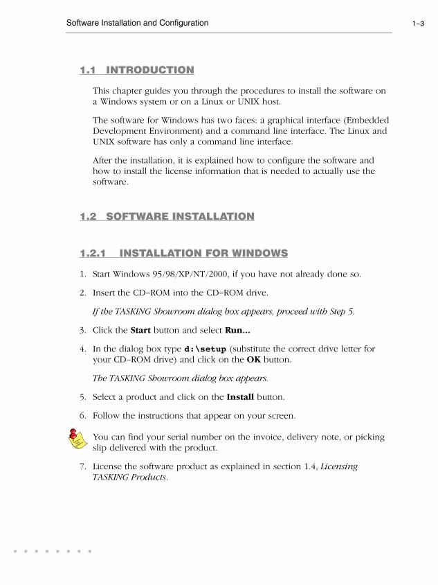
1. Start Windows 95/98/XP/NT/2000, if you have not already done so.
2. Insert the CD-ROM into the CD-ROM drive.
If the TASKING Showroom dialog box appears, proceed with Step 5.
3. Click the Start button and select Run...
4. In the dialog box type d:\setup (substitute the correct drive letter for
your CD-ROM drive) and click on the OK button.
The TASKING Showroom dialog box appears.
5. Select a product and click on the Install button.
6. Follow the instructions that appear on your screen.
You can find your serial number on the invoice, delivery note, or picking
slip delivered with the product.
7. License the software product as explained in section 1.4, LicensingTASKING Products.

User's Manual1-4INSTA
LLATION
1.2.2 INSTALLATION FOR LINUX
Each product on the CD-ROM is available as an RPM package, Debian
package and as a gzipped tar file. For each product the following files are
present:
SWproduct-version-RPMrelease.i386.rpm
swproduct_version-release_i386.deb
SWproduct-version.tar.gz
These three files contain exactly the same information, so you only have
to install one of them. When your Linux distribution supports RPM
packages, you can install the .rpm file. For a Debian based distribution,
you can use the .deb file. Otherwise, you can install the product from the
.tar.gz file.
RPM Installation
1. In most situations you have to be "root" to install RPM packages, so either
login as "root", or use the su command.
2. Insert the CD-ROM into the CD-ROM drive. Mount the CD-ROM on a
directory, for example /cdrom. See the Linux manual pages about mount
for details.
3. Go to the directory on which the CD-ROM is mounted:
cd /cdrom
4. To install or upgrade all products at once, issue the following command:
rpm -U SW*.rpm
This will install or upgrade all products in the default installation directory
/usr/local. Every RPM package will create a single directory in the
installation directory.
The RPM packages are 'relocatable', so it is possible to select a different
installation directory with the --prefix option. For instance when you
want to install the products in /opt, use the following command:
rpm -U --prefix /opt SW*.rpm
For Red Hat 6.0 users: The --prefix option does not work with RPM
version 3.0, included in the Red Hat 6.0 distribution. Please upgrade to
RPM verion 3.0.3 or higher, or use the .tar.gz file installation described
in the next section if you want to install in a non-standard directory.

Software Installation and Configuration 1-5
• • • • • • • •
Debian Installation
1. Login as a user.
Be sure you have read, write and execute permissions in the installation
directory. Otherwise, login as "root" or use the su command.
2. Insert the CD-ROM into the CD-ROM drive. Mount the CD-ROM on a
directory, for example /cdrom. See the Linux manual pages about mount
for details.
3. Go to the directory on which the CD-ROM is mounted:
cd /cdrom
4. To install or upgrade all products at once, issue the following command:
dpkg -i sw*.deb
This will install or upgrade all products in a subdirectory of the default
installation directory /usr/local.
Tar.gz Installation
1. Login as a user.
Be sure you have read, write and execute permissions in the installation
directory. Otherwise, login as "root" or use the su command.
2. Insert the CD-ROM into the CD-ROM drive. Mount the CD-ROM on a
directory, for example /cdrom. See the Linux manual pages about mount
for details.
3. Go to the directory on which the CD-ROM is mounted:
cd /cdrom
4. To install the products from the .tar.gz files in the directory
/usr/local, issue the following command for each product:
tar xzf SWproduct-version.tar.gz -C /usr/local
Every .tar.gz file creates a single directory in the directory where it is
extracted.
User's Manual1-6INSTA
LLATION
1.2.3 INSTALLATION FOR UNIX HOSTS
1. Login as a user.
Be sure you have read, write and execute permissions in the installation
directory. Otherwise, login as "root" or use the su command.
If you are a first time user, decide where you want to install the product.
By default it will be installed in /usr/local.
2. Insert the CD-ROM into the CD-ROM drive and mount the CD-ROM on a
directory, for example /cdrom.
Be sure to use an ISO 9660 file system with Rock Ridge extensions
enabled. See the UNIX manual pages about mount for details.
3. Go to the directory on which the CD-ROM is mounted:
cd /cdrom
4. Run the installation script:
sh install
Follow the instructions appearing on your screen.
First a question appears about where to install the software. The default
answer is /usr/local.
On some hosts the installation script asks if you want to install SW000098,
the Flexible License Manager (FLEXlm). If you do not already have FLEXlm
on your system, you must install it otherwise the product will not work on
those hosts. See section 1.4, Licensing TASKING Products.
If the script detects that the software has been installed before, the
following messages appear on the screen:
*** WARNING ***
SWxxxxxx xxxx.xxxx already installed.
Do you want to REINSTALL? [y,n]
Answering n (no) to this question causes installation to abort and the
following message being displayed:
=> Installation stopped on user request <=

Software Installation and Configuration 1-7
• • • • • • • •
Answer y (yes) to continue with the installation. The last message will be:
Installation of SWxxxxxx xxxx.xxxx completed.
5. If you purchased a protected TASKING product, license the software
product as explained in section 1.4, Licensing TASKING Products.
1.3 SOFTWARE CONFIGURATION
Now you have installed the software, you can configure both the
Embedded Development Environment and the command line environment
for Windows, Linux and UNIX.
1.3.1 CONFIGURING THE EMBEDDED DEVELOPMENT
ENVIRONMENT
After installation, the Embedded Development Environment is
automatically configured with default search paths to find the executables,
include files and libraries. In most cases you can use these settings. To
change the default settings, follow the next steps:
1. Double-click on the EDE icon on your desktop to start the Embedded
Development Environment (EDE).
2. From the Project menu, select Directories...
The Directories dialog box appears.
3. Fill in the following fields:
• In the Executable Files Path field, type the pathname of the
directory where the executables are located. The default directory is
$(PRODDIR)\bin.
• In the Include Files Path field, add the pathnames of the
directories where the compiler and assembler should look for
include files. The default directory is $(PRODDIR)\include.
Separate pathnames with a semicolon (;).
The first path in the list is the first path where the compiler and
assembler look for include files. To change the search order, simply
change the order of pathnames.

User's Manual1-8INSTA
LLATION
• In the Library Files Path field, add the pathnames of the
directories where the linker should look for library files. The default
directory is $(PRODDIR)\lib. Separate pathnames with a
semicolon (;).
The first path in the list is the first path where the linker looks for
library files. To change the search order, simply change the order of
pathnames.
Instead of typing the pathnames, you can click on the Configure...
button.
A dialog box appears in which you can select and add directories, remove
them again and change their order.

Software Installation and Configuration 1-9
• • • • • • • •
1.3.2 CONFIGURING THE COMMAND LINE
ENVIRONMENT
To facilitate the invocation of the tools from the command line (either
using a Windows command prompt or using Linux or UNIX), you can set
environment variables.
You can set the following variables:
EnvironmentVariable
Description
PATH With this variable you specify the directory in which
the executables reside (default: c:\cm16c\bin).
This allows you to call the executables when you
are not in the bin directory.
Usually your system already uses the PATH variable
for other purposes. To keep these settings, you
need to add (rather than replace) the path. Use a
semicolon (;) to separate pathnames.
CM16CINC With this variable you specify one or more additional
directories in which the C compiler cm16c looks for
include files. The compiler first looks in these
directories, then always looks in the default
include directory relative to the installation
directory.
ASM16CINC With this variable you specify one or more additional
directories in which the assembler asm16c looks for
include files. The assembler first looks in these
directories, then always looks in the default
include directory relative to the installation
directory.
CCM16CBIN With this variable you specify the directory in which
the control program ccm16c looks for the
executable tools. The path you specify here should
match the path that you specified for the PATH
variable.
CCM16COPT With this variable you specify options and/or
arguments to each invocation of the control program
ccm16c. The control program processes these
arguments before the command line arguments.
LIBM16C
LIBR8C
With this variable you specify one or more
alternative directories in which the linker lkm16clooks for library files for a specific core. The linker
first looks in these directories, then always looks in
the default lib directory.

User's Manual1-10INSTA
LLATION
DescriptionEnvironmentVariable
LM_LICENSE_FILE With this variable you specify the location of the
license data file. You only need to specify this
variable if the license file is not on its default location
(c:\flexlm for Windows,
/usr/local/flexlm/licenses for UNIX).
TASKING_LIC_WAIT If you set this variable, the tool will wait for a license
to become available, if all licenses are taken. If you
have not set this variable, the tool aborts with an
error message. (Only useful with floating licenses)
TMPDIR With this variable you specify the location where
programs can create temporary files. Usually your
system already uses this variable. In this case you
do not need to change it.
Table 1-1: Environment variables
The following examples show how to set an environment variable using
the PATH variable as an example.
Example for Windows 95/98
Add the following line to your autoexec.bat file:
set PATH=%path%;c:\cm16c\bin
You can also type this line in a Command Prompt window but you will
loose this setting after you close the window.
Example for Windows NT
1. Right-click on the My Computer icon on your desktop and select
Properties from the menu.
The System Properties dialog appears.
2. Select the Environment tab.
3. In the list of System Variables select Path.
4. In the Value field, add the path where the executables are located to the
existing path information. Separate pathnames with a semicolon (;). For
example: c:\cm16c\bin.
5. Click on the Set button, then click OK.
Software Installation and Configuration 1-11
• • • • • • • •
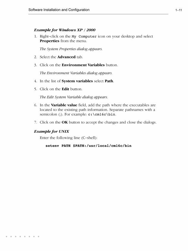
Example for Windows XP / 2000
1. Right-click on the My Computer icon on your desktop and select
Properties from the menu.
The System Properties dialog appears.
2. Select the Advanced tab.
3. Click on the Environment Variables button.
The Environment Variables dialog appears.
4. In the list of System variables select Path.
5. Click on the Edit button.
The Edit System Variable dialog appears.
6. In the Variable value field, add the path where the executables are
located to the existing path information. Separate pathnames with a
semicolon (;). For example: c:\cm16c\bin.
7. Click on the OK button to accept the changes and close the dialogs.
Example for UNIX
Enter the following line (C-shell):
setenv PATH $PATH:/usr/local/cm16c/bin
User's Manual1-12INSTA
LLATION
1.4 LICENSING TASKING PRODUCTS
TASKING products are protected with license management software
(FLEXlm). To use a TASKING product, you must install the license key
provided by TASKING for the type of license purchased.
You can run TASKING products with a node-locked license or with a
floating license. When you order a TASKING product determine which
type of license you need (UNIX products only have a floating license).
Node-locked license (PC only)
This license type locks the software to one specific PC so you can use the
product on that particular PC only.
Floating license
This license type manages the use of TASKING product licenses among
users at one site. This license type does not lock the software to one
specific PC or workstation but it requires a network. The software can then
be used on any computer in the network. The license specifies the
number of users who can use the software simultaneously. A system
allocating floating licenses is called a license server. A license manager
running on the license server keeps track of the number of users.
1.4.1 OBTAINING LICENSE INFORMATION
Before you can install a software license you must have a "License Key"
containing the license information for your software product. If you have
not received such a license key follow the steps below to obtain one.
Otherwise, you can install the license.
Windows
1. Run the License Administrator during installation and follow the steps to
Request a license key from Altium by E-mail.
2. E-mail the license request to your local TASKING sales representative. The
license key will be sent to you by E-mail.

Software Installation and Configuration 1-13
• • • • • • • •
UNIX
1. If you need a floating license on UNIX, you must determine the host ID
and host name of the computer where you want to use the license
manager. Also decide how many users will be using the product. See
section 1.4.5, How to Determine the Host ID and section 1.4.6, How toDetermine the Host Name.
2. When you order a TASKING product, provide the host ID, host name and
number of users to your local TASKING sales representative. The license
key will be sent to you by E-mail.
1.4.2 INSTALLING NODE-LOCKED LICENSES
If you do not have received your license key, read section 1.4.1, ObtainingLicense Information, before continuing.
1. Install the TASKING software product following the installation procedure
described in section 1.2.1, Installation for Windows, if you have not done
this already.
2. Create a license file by importing a license key or create one manually:
Import a license key
During installation you will be asked to run the License Administrator.
Otherwise, start the License Administrator (licadmin.exe) manually.
In the License Administrator follow the steps to Import a license key
received from Altium by E-mail. The License Administrator creates a
license file for you.
Create a license file manually
If you prefer to create a license file manually, create a file called
"license.dat" in the c:\flexlm directory, using an ASCII editor and
insert the license key information received by E-mail in this file. This file is
called the "license file". If the directory c:\flexlm does not exist, create
the directory.
If you wish to install the license file in a different directory, see section
1.4.4, Modifying the License File Location.

User's Manual1-14INSTA
LLATION
If you already have a license file, add the license key information to the
existing license file. If the license file already contains any SERVER lines,
you must use another license file. See section 1.4.4, Modifying the LicenseFile Location, for additional information.
The software product and license file are now properly installed.
1.4.3 INSTALLING FLOATING LICENSES
If you do not have received your license key, read section 1.4.1, ObtainingLicense Information, before continuing.
1. Install the TASKING software product following the installation procedure
described earlier in this chapter on each computer or workstation where
you will use the software product.
2. On each PC or workstation where you will use the TASKING software
product the location of a license file must be known, containing the
information of all licenses. Either create a local license file or point to a
license file on a server:
Add a licence key to a local license file
A local license file can reduce network traffic.
On Windows, you can follow the same steps to import a license key or
create a license file manually, as explained in the previous section with the
installation of a node-locked license.
On UNIX, you have to insert the license key manually in the license file.
The default location of the license file license.dat is in directory
/usr/local/flexlm/licenses for UNIX.
If you wish to install the license file in a different directory, see section
1.4.4, Modifying the License File Location.
If you already have a license file, add the license key information to the
existing license file. If the license file already contains any SERVER lines,
make sure that the number of SERVER lines and their contents match,
otherwise you must use another license file. See section 1.4.4, Modifyingthe License File Location, for additional information.

Software Installation and Configuration 1-15
• • • • • • • •
Point to a license file on the server
Set the environment variable LM_LICENSE_FILE to "port@host", where
host and port come from the SERVER line in the license file. On Windows,
you can use the License Administrator to do this for you. In the License
Administrator follow the steps to Point to a FLEXlm License Server to
get your licenses.
3. If you already have installed FLEXlm v8.4 or higher (for example as part of
another product) you can skip this step and continue with step 4.
Otherwise, install SW000098, the Flexible License Manager (FLEXlm), on
the license server where you want to use the license manager.
It is not recommended to run a license manager on a Windows 95 or
Windows 98 machine. Use Windows XP, NT or 2000 instead, or use UNIX
or Linux.
4. If FLEXlm has already been installed as part of a non-TASKING product
you have to make sure that the bin directory of the FLEXlm product
contains a copy of the Tasking daemon. This file is present on every
product CD that includes FLEXlm, in directory licensing.
5. On the license server also add the license key to the license file. Follow
the same instructions as with "Add a license key to a local license file" in
step 2.
See the FLEXlm PDF manual delivered with SW000098, which is present
on each TASKING product CD, for more information.

User's Manual1-16INSTA
LLATION
1.4.4 MODIFYING THE LICENSE FILE LOCATION
The default location for the license file on Windows is:
c:\flexlm\license.dat
On UNIX this is:
/usr/local/flexlm/licenses/license.dat
If you want to use another name or directory for the license file, each user
must define the environment variable LM_LICENSE_FILE.
If you have more than one product using the FLEXlm license manager you
can specify multiple license files to the LM_LICENSE_FILE environment
variable by separating each pathname (lfpath) with a ';' (on UNIX ':'):
Example Windows:
set LM_LICENSE_FILE=c:\flexlm\license.dat;c:\license.txt
Example UNIX:
setenv LM_LICENSE_FILE
/usr/local/flexlm/licenses/license.dat:/myprod/license.txt
If the license file is not available on these hosts, you must set
LM_LICENSE_FILE to port@host; where host is the host name of the
system which runs the FLEXlm license manager and port is the TCP/IP port
number on which the license manager listens.
To obtain the port number, look in the license file at host for a line starting
with "SERVER". The fourth field on this line specifies the TCP/IP port
number on which the license server listens. For example:
setenv LM_LICENSE_FILE 7594@elliot
See the FLEXlm PDF manual delivered with SW000098, which is present
on each TASKING product CD, for detailed information.

Software Installation and Configuration 1-17
• • • • • • • •
1.4.5 HOW TO DETERMINE THE HOST ID
The host ID depends on the platform of the machine. Please use one of
the methods listed below to determine the host ID.
Platform Tool to retrieve host ID Example host ID
HP-UX lanscan(use the station address without
the leading '0x')
0000F0050185
Linux hostid 11ac5702
SunOS/Solaris hostid 170a3472
Windows licadmin (License Administrator,
or use lmhostid)
0060084dfbe9
Table 1-2: Determine the host ID
On Windows, the License Administrator (licadmin) helps you in the
process of obtaining your license key.
If you do not have the program licadmin you can download it from our
Web site at: http://www.tasking.com/support/flexlm/licadmin.zip . It is
also on every product CD that includes FLEXlm, in directory licensing.
1.4.6 HOW TO DETERMINE THE HOST NAME
To retrieve the host name of a machine, use one of the following methods.
Platform Method
UNIX hostname
Windows NT licadmin or:
Go to the Control Panel, open "Network". In the
"Identification" tab look for "Computer Name".
Windows XP/2000 licadmin or:
Go to the Control Panel, open "System". In the "Computer
Name" tab look for "Full computer name".
Table 1-3: Determine the host name

User's Manual1-18INSTA
LLATION

2
GETTING STARTEDC
HA
PT
ER

User's Manual2-2G
ET
TIN
G S
TAR
TE
D 2
CH
AP
TE
R
Getting Started 2-3
• • • • • • • •
2.1 INTRODUCTION
With the TASKING M16C suite you can write, compile, assemble, link and
locate applications for the several M16C cores.
Embedded Development Environment
The TASKING Embedded Development Environment (EDE) is a Windows
application that facilitates working with the tools in the toolchain and also
offers project management and an integrated editor.
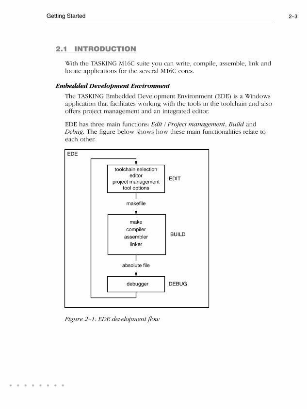
EDE has three main functions: Edit / Project management, Build and
Debug. The figure below shows how these main functionalities relate to
each other.
makefile
make
compiler
absolute file
debugger
assembler
linker
EDE
project management
editor
tool options
toolchain selection
EDIT
BUILD
DEBUG
Figure 2-1: EDE development flow

User's Manual2-4G
ET
TIN
G S
TAR
TE
D
In the Edit part you make all your changes:
- create a project space
- create and maintain one or more projects in a project space
- add, create and edit source files in a project
- set the options for each tool in the toolchain
- select another toolchain if you want to create an application for
another target than the M16C.
In the Build part you build your files:
- a makefile (created by the Edit part) is used to invoke the needed
toolchain components, resulting in an absolute object file.
In the Debug part you can debug your project:
- call the TASKING debugger �CrossView Pro" with the generated
absolute object file.
This Getting Started Chapter guides you step-by-step through the most
important features of EDE
The TASKING EDE is an embedded environment and differs from a nativeprogram development.
A native program development environment is often used to develop
applications for systems where the host system and the target are the
same. Therefore, it is possible to run a compiled application directly from
the development environment.
In an embedded environment, however, a simulator or target hardware is
required to run an application. TASKING offers a number of simulators
and target hardware debuggers.
Toolchain overview
You can use all tools in the toolchain from the embedded development
environment (EDE) and from the command line in a Command Prompt
window or a UNIX shell.
The next illustration shows all components of the M16C toolchain with
their input and output files.

Getting Started 2-5
• • • • • • • •
assembly file
assembler
relocatable object file
C++ compiler
C++ source file
.cc
C source file
C compiler
.ic
cpm16c
cm16c
asm16c
relocatable object library.a
archiver
arm16c
list file .lst
.src
.obj
C source file
assembly file
(hand coded)
.c
.asm
(hand coded)
error messages .ers
linker
relocatable linker object file
lkm16c
.eln
linker map file .map
error messages .elk
linker script file
.lsl
relocatable linker object file .eln
error messages .err
memory definition
.mdffile
CrossView Pro
debugger
Motorola S-record
absolute object file
.s
Intel Hex
absolute object file
.hex
ELF/DWARF 2
absolute object file
.elf
execution
environment
xfwm16c
Figure 2-2: M16C toolchain

User's Manual2-6G
ET
TIN
G S
TAR
TE
D
The following table lists the file types used by the M16C toolchain.
Extension Description
Source files
.cc C++ source file, input for the C++ compiler
.c C source file, input for the C compiler
.asm Assembler source file, hand coded
.lsl Linker script file using the Linker Script Language
Generated source files
.ic C source file, generated by the C++ compiler, input for the C
compiler
.src Assembler source file, generated by the C compiler, does not
contain macros
Object files
.obj ELF/DWARF relocatable object file, generated by the assembler
.a Archive with ELF/DWARF object files
.eln Relocatable linker output file
.elf ELF/DWARF absolute object file, generated by the locating part
of the linker
.hex Absolute Intel Hex object file
.s Absolute Motorola S-record object file
List files
.lst Assembler list file
.map Linker map file
.mdf Memory definition file
.mcr MISRA C report file
Error list files
.err Compiler error messages file
.ers Assembler error messages file
.elk Linker error messages file
Table 2-1: File extensions

Getting Started 2-7
• • • • • • • •
2.2 WORKING WITH PROJECTS IN EDE
EDE is a complete project environment in which you can create and
maintain project spaces and projects. EDE gives you direct access to the
tools and features you need to create an application from your project.
A project space holds a set of projects and must always contain at least one
project. Before you can create a project you have to setup a project space.
All information of a project space is saved in a project space file (.psp):
• a list of projects in the project space
• history information
Within a project space you can create projects. Projects are bound to a
target! You can create, add or edit files in the project which together form
your application. All information of a project is saved in a project file(.pjt):
• the target for which the project is created
• a list of the source files in the project
• the options for the compiler, assembler, linker and debugger
• the default directories for the include files, libraries and executables
• the build options
• history information
When you build your project, EDE handles file dependencies and the
exact sequence of operations required to build your application. When
you push the Build button, EDE generates a makefile, including all
dependencies, and builds your application.
Overview of steps to create and build an application
1. Create a project space
2. Add one or more projects to the project space
3. Add files to the project
4. Edit the files
5. Set development tool options
6. Build the application

User's Manual2-8G
ET
TIN
G S
TAR
TE
D
2.3 START EDE
Start EDE
• Double-click on the EDE shortcut on your desktop.
- or -
Launch EDE via the program folder created by the installation program.
Select Start -> Programs -> TASKING toolchain -> EDE.
Figure 2-3: EDE icon
The EDE screen contains a menu bar, a toolbar with command buttons,
one or more windows (default, a window to edit source files, a project
window and an output window) and a status bar.
Output WindowContains several tabs to display
and manipulate results of EDE
operations. For example, to view
the results of builds or compiles.
Document WindowsUsed to view and edit files.
Project WindowContains several
tabs for viewing
information about
projects and other
files.
Compile Build Rebuild Debug On-line ManualsProject Options
Figure 2-4: EDE desktop
Getting Started 2-9
• • • • • • • •
2.4 USING THE SAMPLE PROJECTS
When you start EDE for the first time (see section 2.3, Start EDE), EDE
opens with a ready defined project space that contains several sample
projects. Each project has its own subdirectory in the examples directory.
Each directory contains a file readme.txt with information about the
example. The default project is called demo.pjt and contains a CrossView
Pro debugger example.
Select a sample project
To select a project from the list of projects in a project space:
1. In the Project Window, right-click on the project you want to open.
A menu appears.
2. Select Set as Current Project.
The selected project opens.
3. Read the file readme.txt for more information about the selected sample
project.
Building a sample project
To build the currently active sample project:
• Click on the Execute 'Make' command button.
Once the files have been processed you can inspect the generated messagesin the Build tab of the Output window.

User's Manual2-10G
ET
TIN
G S
TAR
TE
D
2.5 CREATE A NEW PROJECT SPACE WITH A PROJECT
Creating a project space is in fact nothing more than creating a project
space file (.psp) in an existing or new directory.
Create a new project space
1. From the File menu, select New Project Space...
The Create a New Project Space dialog appears.
2. In the the Filename field, enter a name for your project space (for
example MyProjects). Click the Browse button to select a directory first
and enter a filename.
3. Check the directory and filename and click OK to create the .psp file in
the directory shown in the dialog.
A project space information file with the name MyProjects.psp iscreated and the Project Properties dialog box appears with the project spaceselected.

Getting Started 2-11
• • • • • • • •
Add a new project to the project space
4. In the Project Properties dialog, click on the Add new project to project
space button (see previous figure).
The Add New Project to Project Space dialog appears.

User's Manual2-12G
ET
TIN
G S
TAR
TE
D
5. Give your project a name, for example getstart\getstart.pjt (a
directory name to hold your project files is optional) and click OK.
A project file with the name getstart.pjt is created in the directorygetstart, which is also created. The Project Properties dialog box appearswith the project selected.
Add new files to the project
Now you can add all the files you want to be part of your project.
6. Click on the Add new file to project button.
The Add New File to Project dialog appears.

Getting Started 2-13
• • • • • • • •
7. Enter a new filename (for example hello.c) and click OK.
A new empty file is created and added to the project. Repeat steps 6 and 7 ifyou want to add more files.
8. Click OK.
The new project is now open. EDE loads the new file(s) in the editor inseparate document windows.
EDE automatically creates a makefile for the project (in this case
getstart.mak). This file contains the rules to build your application.
EDE updates the makefile every time you modify your project.
Edit your files
9. As an example, type the following C source in the hello.c document
window:
#include <stdio.h>
void main(void)
{
printf("Hello World!\n");
}
10. Click on the Save the changed file <Ctrl-S> button.
EDE saves the file.

User's Manual2-14G
ET
TIN
G S
TAR
TE
D
2.6 SET OPTIONS FOR THE TOOLS IN THE TOOLCHAIN
The next step in the process of building your application is to select a
target processor and specify the options for the different parts of the
toolchain, such as the C compiler, assembler, linker and debugger.
Select a target processor
1. From the Project menu, select Project Options...
The Project Options dialog appears.
2. Expand the Processor entry and select Processor Definition.
3. In the Select core list select (for example) M16C.
4. In the Select group list select (for example) M16C62A.
5. In the Select processor list select (for example) M30624FGAFP/GP.
6. Optional for some processors, select a Processor mode.
7. Click OK to accept the new project settings.

Getting Started 2-15
• • • • • • • •
Set tool options
1. From the Project menu, select Project Options...
The Project Options dialog appears. Here you can specify options that arevalid for the entire project. To overrule the project options for the currentlyactive file instead, from the Project menu select Current File Options...
2. Expand the C Compiler entry.
The C Compiler entry contains several pages where you can specify Ccompiler settings.
3. For each page make your changes. If you have made all changes click OK.
The Cancel button closes the dialog without saving your changes. With
the Default... button you can restore the default project options (for the
current page, or all pages in the dialog).
4. Make your changes for all other entries (Assembler, Linker, CrossView Pro,
Flasher) of the Project Options dialog in a similar way as described above
for the C compiler.
If available, the Options string field shows the command line options
that correspond to your graphical selections.

User's Manual2-16G
ET
TIN
G S
TAR
TE
D
Synchronize options with the ROM monitor
If you use a ROM monitor for debugging, you must be sure that all EDE
settings are correct for communicating with the ROM monitor. If the ROM
monitor target board is connected to your PC, EDE can automatically set
the correct options based on the ROM monitor. To do this:
1. Click on the Synchronize options with the ROM monitor button.
The Synchronize Options dialog appears.
2. Specify the Serial port and Baud rate at which the ROM monitor is
connected and click Scan. If you do not know the port or baud rate, you
can click Scan All to scan all COM ports for the ROM monitor.
3. Click Sync to synchronize the shown options with the current project.
A message appears that the current project has been synchronized with theROM monitor.
4. Click OK to close the message box.
5. Click Close to close the dialog.
Getting Started 2-17
• • • • • • • •
2.7 BUILD YOUR APPLICATION
If you have set all options, you can actually compile the file(s). This results
in an absolute ELF/DWARF object file which is ready to be debugged.
Build your Application
To build the currently active project:
• Click on the Execute 'Make' command button.
The file is compiled, assembled, linked and located. The resulting file isgetstart.elf.
The build process only builds files that are out-of-date. So, if you click
Make again in this example nothing is done, because all files are
up-to-date.
Viewing the Results of a Build
Once the files have been processed, you can see which commands have
been executed (and inspect generated messages) by the build process in
the Build tab of the Output window.
This window is normally open, but if it is closed you can open it by
selecting the Output menu item in the Window menu.
Compiling a Single File
1. Select the window (document) containing the file you want to compile or
assemble.
2. Click on the Execute 'Compile' command button. The following button
is the execute Compile button which is located in the toolbar.
If you selected the file hello.c, this results in the compiled and assembledfile hello.obj.

User's Manual2-18G
ET
TIN
G S
TAR
TE
D
Rebuild your Entire Application
If you want to compile, assemble and link/locate all files of your project
from scratch (regardless of their date/time stamp), you can perform a
rebuild.
• Click on the Execute 'Rebuild' command button. The following
button is the execute Rebuild button which is located in the toolbar.
2.8 HOW TO BUILD YOUR APPLICATION ON THE
COMMAND LINE
If you are not using EDE, you can build your entire application on the
command line. The easiest way is to use the control program ccm16c
1. In a text editor, write the file hello.c with the following contents:
#include <stdio.h>
void main(void)
{
printf("Hello World!\n");
}
2. Build the file getstart.elf:
ccm16c -ogetstart.elf hello.c -v
The control program calls all tools in the toolchain. The -v option shows allthe individual steps. The resulting file is getstart.elf.

Getting Started 2-19
• • • • • • • •
2.9 DEBUG GETSTART.ELF
The application getstart.elf is the final result, ready for execution
and/or debugging. The debugger uses getstart.elf for debugging but
needs symbolic debug information for the debugging process. This
information must be included in getstart.elf and therefore you need
to compile and assemble hello.c once again.
ccm16c -g -ogetstart.elf hello.c
Now you can start the debugger with getstart.elf and see how it
executes.
Start CrossView Pro
• Click on the Debug application button.
CrossView Pro is launched. CrossView Pro will automatically download thefile getstart.elf for debugging.
See the CrossView Pro Debugger User's Manual for more information.

User's Manual2-20G
ET
TIN
G S
TAR
TE
D

3
C LANGUAGEC
HA
PT
ER

User's Manual3-2C
LA
NG
UA
GE
3
CH
AP
TE
R

C Language 3-3
• • • • • • • •
3.1 INTRODUCTION
The TASKING C cross-compiler (cm16c) fully supports the ISO C99
standard. In addition, it adds extra possibilities to write fast and compact
code for the M16C and to use the special functions of the M16C.
In addition to the standard C language, the compiler supports the
following:
• extra data type __bit
• intrinsic (built-in) functions that result in M16C specific assembly
instructions
• pragmas to control the compiler from within the C source
• predefined macros
• the possibility to use assembly instructions in the C source
• keywords to specify memory types for data and functions
• attributes to specify alignment and absolute addresses
• keywords for programming interrupt routines
• libraries
All non-standard keywords have two leading underscores (__).
This chapter first describes programming strategies and tips for writing
optimal code for the M16C. Next, the M16C specific characteristics of the C
language are described into more detail.

User's Manual3-4C
LA
NG
UA
GE
3.2 PROGRAMMING STRATEGIES
3.2.1 MEMORY SPACES
Choosing Memory Spaces
The TASKING M16C toolchain introduces several qualifiers to control how
and where you want to allocate C objects in memory. Among others, the
following memory qualifiers exist:
• __far anywhere in the 20 bit space, objects can be of any size.
• __paged anywhere in the 20 bit space, objects must be smaller
than 64 kB and will never cross 64k boundaries
• __near first 64k
• __bita first 8k (the bitaddressable space)
Most M16C instructions can address operands in memory only if they lie in
the first 64k. For far addresses, expensive load/store instructions are
needed. For this reason, using __near qualified variables generates much
faster code than using __far or __paged variables.
A pointer to a __near qualified object fits in one 16 bit address register,
for a pointer to a __far or __paged object the double register A1A0 is
needed. Also, pointer arithmetic for __near pointers is much faster.
__paged qualified objects are guaranteed not to be allocated accross 64k
boundaries. Therefor, pointer arithmetic on pointers to paged memory
only requires updates of the A0 register. For pointers to far memory both
A1 and A0 need to be altered. So, pointer arithmetic is often twice as fast
for pointers to paged memory.
The stack lies always in the first 64k bytes, so a variable on the stack is
implicitly __near qualified. This means that automatic variables are
always fastest (regardless of the chosen memory model).
Objects qualified with __bita are bit-addressable. This means that setting
and getting individual bits can be done with the fast bit instructions of the
M16C.

C Language 3-5
• • • • • • • •
String and Constant Allocation
Strings and constants can be allocated in both ROM and RAM memory. If
allocated in RAM, they have to be initialized from a copy in ROM during
program startup. So allocating in ROM saves both memory and time. You
can achieve this by enabling the options Keep strings in ROM and Keep
constants in ROM on the Code Generation page of the C Compiler
options. Note that strings in ROM cannot be modified at run-time.
Usual M16C hardware configurations have no ROM in the near space (first
64k of memory). So by default, even with Keep strings in ROM and
Keep constants in ROM enabled, __near qualified objects in those cases
are allocated in RAM.
In case your hardware does have ROM in the near space, you should
enable the option ROM is available in first 64k of memory on the Code
Generation page of the C Compiler options.
Choosing a Memory Model
The memory model determines the default memory space qualifier for
objects. It also determines which library must be linked (library functions
have no memory qualifiers in their prototypes).
In the small memory model, all objects get the __near qualifier implicitly.
In the large memory model, all objects get the __far qualifier implicitly.
In the medium memory model, all constants, string literals and pointers
get the __paged qualifier implicitly, while variables get the __near
qualifier.
Note that the medium memory model is specifically tailored to allocate
constants and strings in ROM. Constants get the __paged qualifier
implicitly, so they can be put in ROM. Other variables get the __near
qualifier for optimal performance. By default, pointers are implicitly
__paged qualified, so they can point to both constants and variables.
Variables that do not fit in near memory can easily be qualified as
__paged, as this leads to no problems with default pointers and library
calls. For before mentioned reasons, the medium memory model is the
default.

User's Manual3-6C
LA
NG
UA
GE
Strategies
As explained above, allocating everything in the near memory space by
using the small memory model yields the fastest and most compact code.
However, for larger projects this obviously is not an option. To reap some
of the benefits though, you can use memory qualifiers to force frequently
used and/or small variables in near memory and rarely used and/or large
variables in far memory.
One strategy is to use the small memory model, but qualify large objects
as __paged or __far when absolutely necessary. 'Far' pointers cannot be
cast to 'near' pointers. The compiler will check this, but it can be
inconvenient, especially for library calls.
Another strategy is the other way around: use the large memory model
and qualify, where possible, variables as __near. Be careful with pointers
though, default pointers are __far qualified and will produce inefficient
code if used with __near objects.
3.2.2 BIT PROGRAMMING
The M16C has efficicient instructions to manipulate individual bits.
However, these instructions are usually only available for variables in the
first 8kB of memory (the bita space).
To generate these fast bit instructions, the compiler cm16c supports the
__bit basic type. This type is implicitly allocated in the bit space.
Pointers to __bit variables are special, since they use bit addresses
instead of bytes. Therefore, __bit variables do have some restrictions (see
subsection Bit Data Type in section 3.3, Data Types).
By using the __bit type, the compiler cm16c can also generate fast bit
instructions for bitfield operations. To make this possible, you have to
allocate the structure in the bita space using the __bita memory qualifier:
__bita struct
{
int bit0 : 1;
int bit1 : 1;
int bit2 : 1;
} threebits;
is equivalent to:

C Language 3-7
• • • • • • • •
struct
__bit bit0;
__bit bit1;
__bit bit2;
} threebits;
Note however that the upper example places bitfields in the bita space,
making each bit within a byte addressable (mau 8), whereas the lower
example places bits in the bit space making each bit directly addressable
(mau 1).
Former TASKING M16C toolchains supported __atbit() for an
equivalent construction. While this is still supported, its use is deprecated.
3.2.3 FLOATING-POINT
Floating-point operations are not supported by M16C hardware. Instead
run-time functions are used to handle floating-points. Try to avoid using
floating-point and use integers instead.
If you still need floating-point arithmetric, try to use single precision
floating-point. Arithmetic with floats is much faster than with doubles.
To illustrate this using the whetstone example:
Whetstone Float Double Achievement
whet.c 1869 bytes 2335 bytesSize of module whet_CO is 20%
smaller for float than for double.
whet.elf 9618 bytes 15079 bytesSize of application is 36% smaller
for float than for double.
time 36 sec 220 secExecution time is 84% faster for
float than for double.
Floating-point constants like 1.0 are double precision according to the C
standard. If you only need single precision, make sure to use the float
postfix notation for constants, for example 1.0f.

User's Manual3-8C
LA
NG
UA
GE
In ISO C99 all library function like double cos(double) have a single
precision parallel function like float cosf(float). Use these single
precision functions whenever possible. The tgmath.h header file even
contains type generic functions which automatically call the best variant
(see section 2.2.13, Math.h and Tgmath.h in Chapter Libraries of the
Reference Manual).
Variable argument lists can never be float, only double. But there is one
exception: with the option Use single precision float point only on the
floating-point page of the Compiler options, floats are used everywhere
instead of doubles, also in varargs! This is the only way to have single
precision floats in vararg functions like printf.
3.2.4 GENERAL OPTIMIZATION TIPS
Try to use local variables instead of global variables because:
• Locals can often be allocated in registers.
• Memory on the stack can be reused by sibling functions
• The compiler must assume external function calls read and write all
global variables, which might make some optimizations impossible.
Avoid taking the address of variables (using the & operator) because:
• Variables whose address is taken cannot be allocated in a register
• The compiler must assume every external function can call the variable
by reference, precluding some optimizations.
Optimization settings
Inline function calls
• Enable Function inlining (or choose the Agressive (all) optimization
level) on the Optimization page of the Compiler options (command
line option -Oi or -O3)
• Use function qualifiers inline and __noinline to give extra hints to
the compiler.
• Inlining results in faster, but often in larger code if Optimize for size is
not set.
• Debugging inlined code can be harder
Reverse inlining

C Language 3-9
• • • • • • • •
• The compiler has an option to 'reverse inline' functions: by making a
compiler-generated function for repeated code sequences. This always
results in smaller, but slower code. To get the smallest code size
possible, this optimization can really help.
• You can enable both Function inlining and Reverse inlining at the
same time. Inlining may increase the possibilities for reverse inlining
which leads to faster and smaller code.
• The cm16c compiler offers the option to compile several C-modules in
one single pass, this is called MIL linking. This makes several compiler
optimizations much more effective, notably inlining and reverse
inlining.
• To enable MIL linking, enable the option MIL linking (compile
multiple C files simultaneously) on the Optimization page of the
C Compiler options, or choose Agressive (all) optimization).
Be cautious with inline assembly (__asm)
• __asm() statements are not analyzed by the compiler, they are copied
verbatim to the output assembly. Because of this, the compiler cannot
optimize the surrounding code. It is recommended to use plain C and
intrinsic functions whenever possible.

User's Manual3-10C
LA
NG
UA
GE
3.3 DATA TYPES
The TASKING C compiler for the M16C architecture supports the following
data types:
Type KeywordSize(bit)
Align(bit)
Ranges
Bit __bit 1 1 0 or 1
Boolean _Bool 1 8 0 or 1
Character char
signed char8 8 -27 .. 27-1
unsigned char 8 8 0 .. 28-1
Integral short
signed short
int
signed int
16 8 / 16* -215 .. 215-1
unsigned short
unsigned int16 8 / 16* 0 .. 216-1
enum 1
8
16
8
8 / 16*
8 / 16*
0 or 1
-27 .. 27-1
-215 .. 215-1
long
signed long32 8 / 16* -231 .. 231-1
long long
signed
long long
64 8 / 16* -263 .. -263-1
unsigned long 32 8 / 16* 0 .. 232-1
unsigned
long long64 8 / 16* 0 .. 264-1
Pointer pointer to
__sfr, __bita16 8 / 16* 0 .. 213-1
pointer to
__near16 8 / 16* 0 .. 216-1
pointer to
__far, __paged32 8 / 16* 0 .. 220-1

C Language 3-11
• • • • • • • •
RangesAlign(bit)
Size(bit)
KeywordType
Floating
Pointfloat 32 8 / 16*
-3.402e38 .. -1.175e-38
1.175e-38 .. 3.402e38
double
long double64 8 / 16*
-1.797e308 .. -2.225e-308
2.225e-308 .. 1.797e308
float
_Imaginary32 8 / 16*
-3.402e38i .. -1.175e-38i
1.175e-38i .. 3.402e38i
float _Complex 32+32 8 / 16* real part + imaginary part
double/
long double
_Imaginary64 8 / 16*
-1.797e308i .. -2.225e-308i
2.225e-308i .. 1.797e308i
double/
long double
_Complex64+64 8 / 16* real part + imaginary part
Table 3-1: Data Types
* For the marked data types, the alignment is 16 if you specify compiler
option --align, otherwise the alignment is 8.
When you use the enum type, the compiler will use the smallest sufficient
integer type (_Bool, char, int), unless you use compiler option
--integer-enumeration (always use 16-bit integers for enumeration).
float is implemented in little endian IEEE 32-bit single precision format.
double is implemented in little endian IEEE 64-bit double precision
format.
When you compile for the R8C/tiny (compiler option --r8c) __far and
__paged are the same as __near.
See also the Applications Binary Interface (ABI).

User's Manual3-12C
LA
NG
UA
GE
Bit Data Type
You can use the __bit type to define scalars in the bit-addressable area
and for the return type of functions. A struct containing bit fields cannot
be used for this purpose, for example because the struct is aligned at a
byte boundary. Unlike the _Bool type the __bit type is aligned on a bit
boundary.
The following rules apply to __bit type variables:
• A __bit type variable is always unsigned.
• A __bit type variable can be exchanged with all other type-variables.
The compiler generates the correct conversion.
A __bit type variable is like a boolean. Therefore, if you convert an
int type variable to a __bit type variable, it becomes 1 (true) if the
integer is not equal to 0, and 0 (false) if the integer is 0. The next two
C source lines have the same effect:
bit_variable = int_variable;
bit_variable = int_variable ? 1 : 0;
• Pointer to __bit is allowed, but you cannot take the address of a bit
on the stack.
• The __bit type is allowed as a structure member. However, a bit
structure can only contain members of type __bit, and you cannot
push a bit structure on the stack or return a bit structure via a function.
• A union of a __bit structure and another type is not allowed.
• A __bit type variable is allowed as a parameter of a function.
• A __bit type variable is allowed as a return type of a function.
• A __bit typed expression is allowed as switch expression.
• The sizeof of a __bit type is 1.
• Global or static __bit type variable can be initialized.
• A __bit type variable can be declared volatile.
3.4 MEMORY QUALIFIERS
You can use memory qualifiers to allocate static objects in a particular part
of the addressing space of the processor.
In addition, you can place variables at absolute addresses with the
keyword __at().

C Language 3-13
• • • • • • • •
3.4.1 MEMORY TYPE QUALIFIERS
In the TASKING C language you can specify that a variable must lie in a
specific part of memory. You can do this with a memory type qualifier.
You can use the following memory type qualifiers:
Qualifier Description
__bita Bit-addressable RAM (first 8 kB of memory)
__sfr Defines a special function register. Special optimizations are
performed on this type of variables. Data is located in the
SFR space.
__near Data is located in the first 64 kB of memory
__far Data is located anywhere in memory
__paged Data is located in a 64 kB page, anywhere in memory
__rom Data defined with this qualifier is placed in ROM. This
section is excluded from automatic initialization by the
startup code. __rom is not the same as const.
Table 3-2: Memory type qualifiers
If you do not specify a memory type qualifier for the M16C, the variable
implicitly gets the default memory type of the selected memory model (see
section 3.5, Memory Models).
Functions are by default allocated in ROM. In this case you can omit the
memory qualifier __rom. You cannot use memory qualifiers for function
return values.
See also the assembler directive DEFSECT (Declare section), in section
3.3, Assembler Directives, in Chapter Assembly Language of the ReferenceManual.
Examples using explicit memory types
__rom char text[] = "No smoking";
__bita int array[10][4];
The memory type qualifiers are treated like any other data type specifier
(such as unsigned). This means the examples above can also be declared
as:
User's Manual3-14C
LA
NG
UA
GE
char __rom text[] = "No smoking";
int __bita array[10][4];
Pointers
Pointers declarations can have two memory type qualifiers. For example,
the pointer itself can reside in the bita space, while pointing to a function
that resides in the rom space: For example:
__rom char *__bita p; /* pointer residing in BITA,
pointing to ROM */
In this declaration pointer p is qualified with __bita (allocated in
bit-addressable RAM), but points to a char which is qualified with __rom
(allocated in ROM). The memory type qualifier used to the left of the '*',
specifies the target memory of the pointer, the memory type qualifier used
to the right of the '*', specifies the storage memory of the pointer.
The TASKING M16C C compiler recognizes two types of pointers: pointers
with a size of 2 bytes or 4 bytes in memory. Pointers to __sfr, __bita
are 13-bit pointers (2 bytes in memory) and pointers to __near are 16-bit
pointers and can point only to locations in the lowest 64K bytes of
memory. Pointers to __far and __paged are 20-bit pointers (4 bytes in
memory) and can point anywhere in memory. Pointer arithmetic with
__far is 32 bits, whereas with __paged 16-bit pointer arithmetic is used,
because an __paged object is always located in a 64 kB page.
Function pointers for the M16C core are always __far pointers and
function pointers for the R8C core are always __near pointers.
Structures
A structure declaration is intended to specify the layout of a structure or
union. A structure declaration itself, nor its members can be bound to any
storage area. (Members of type pointer of course can point to variables in
a particular memory space).
A tag then is used to define objects of the declared structure type. You can
qualify this object with a memory type qualifier to allocate it in a particular
memory space. The whole object, including its members is allocated in the
specified memory.
struct S {
__near int i; /* referring to storage: not correct */
__far char *p; /* used to specify target memory: correct */
};

C Language 3-15
• • • • • • • •
In the declaration above the compiler ignores the erroneous __near
memory type qualifier.
__near struct S my_struct;
The compiler now reserves 6 bytes for the object my_struct: 2 bytes for
int i and 4 bytes for pointer p which points to a variable in far memory.
The following example is also correct:
__near struct S {
int i;
__near char *p;
} my_struct
The example above combines the structure declaration S and the structure
definition of my_struct. In this case the object my_struct is located in
near memory where 4 bytes are reserved: 2 bytes for int i and 2 bytes
for pointer p which points to a variable in near memory.
Typedef
Typedef declarations follow the same scope rules as any declared object.
Typedef names may be (re-)declared in inner blocks but not at the
parameter level. However, in typedef declarations, memory type
qualifiers are allowed. A typedef declaration should at least contain one
type qualifier.
typedef __near int NEARINT; /* storage type __near: OK */
typedef int __near *PTR; /* PTR points to an int in __near
PTR resides in default memory */
3.4.2 ACCESSING PERIPHERALS FROM C: __SFR
It is easy to access Special Function Registers (SFRs) that relate to
peripherals from C. The SFRs are defined in a special function register file
(*.sfr) as symbol names for use with the compiler. An SFR file contains
the names of the SFRs and the bits in the SFRs.
Based on the target processor, the compiler includes the correct SFR file.
(See compiler option -C in chapter Tool Options of the Reference Manual).Using the correct SFR file, you can access the special function registers and
its individual bits using the symbols defined in the SFR file.

User's Manual3-16C
LA
NG
UA
GE
Example use in C for the M30100 target with SFR file regm30100.sfr
P0 = 0x88; // fill port register p0
P1_3 = 1; // set bit 3 of port register P1
if (P1_4 == 1)
{
P1_3 = 0;
}
INT0EN = 1; // use of bit name: set the int0 interrupt
// enable bit in the external interrupt
// enable register.
The compiler generates:
_main: type func
mov.b #136, 224
bset 3,225
btst 4,225
jltu _2
bclr 3,225
_2:
bset 0,150
You can easily find a list of defined SFRs and defined bits by inspecting
the SFR file for a specific core. The files are named regcore.sfr, for
example regm30100.sfr.
Define Special Function Registers: __sfr
With the __sfr memory type qualifier you can define a symbol as a
Special Function Register (SFR). The compiler may assume that special SFR
operations can be performed on such symbols. The compiler can decide
to use bit instructions for those special function registers that are bit
accessible. For example, if bits are defined in the SFR definition, these bits
can be accessed using bit instructions.

C Language 3-17
• • • • • • • •
A typical definition of a special function register looks as follows:
typedef struct
_Bool __b0:1;
_Bool __b1:1;
_Bool __b2:1;
_Bool __b3:1;
_Bool __b4:1;
_Bool __b5:1;
_Bool __b6:1;
_Bool __b7:1;
...
_Bool __b31:1;
} __bitstruct_t;
#define P0 (*(__sfr unsigned char *)0x00E0)
#define P0_0 ((__sfr __bitstruct_t *)&P0)->__b0
#define INTEN (*(__sfr unsigned char *)0x0096)
#define INT0EN ((__sfr __bitstruct_t *)&INTEN)->__b0
Example of access to the SFR:
P0 = 0x56;
P0_0 = INT0EN;
It is incorrect to optimize away access to registers. Therefore, the compiler
deals with the special function registers as if they were declared with the
volatile qualifier. In fact __sfr is treated as volatile __bita.
Non-initialized global SFR variables are not cleared at program startup. For
example:
__sfr int i; // global SFR not cleared
It is not allowed to initialize global SFR variables. SFR variables are not
initialized at startup. For example:
__sfr int j=10; // not allowed to initialize global SFR
See also compiler option -C (Use SFR definitions for CPU) in section
Compiler Options in Chapter Tool Options of the Reference Manual.

User's Manual3-18C
LA
NG
UA
GE
3.4.3 DECLARE A DATA OBJECT AT AN ABSOLUTE
ADDRESS: __at()
Just like you can declare a variable in a specific part of memory, you can
also place an object at an absolute address in memory. This may be useful
to interface with other programs using fixed memory schemes, or to access
special function registers.
With the attribute __at() you can specify an absolute address.
Examples
unsigned char Display[80*24] __at( 0x2000 )
The array Display is placed at address 0x2000. In the generated
assembly, an absolute section is created. On this position space is reserved
for the variable Display.
int myvar __at(0x100)=1;
The variable myvar is placed at address 0x100 and is initialized at 1.
void f(void) __at( 0xf0ff + 1 ) { }
The function f is placed at address 0xf100.
Restrictions
Take note of the following restrictions if you place a variable at an
absolute address:
• The argument of the __at() attribute must be a constant address
expression.
• You can place only variables with static storage at absolute addresses.
Parameters of functions, or automatic variables within functions cannot
be placed at absolute addresses.
• When declared extern, the variable is not allocated by the compiler.
When the same variable is defined within another module but on a
different address, the compiler, assembler or linker will not notice.
• When the variable is declared static, no public symbol will be
generated (normal C behavior).
• You cannot place structure members at absolute addresses.
• Absolute variables cannot overlap each other. If you define two
absolute variables at the same address, the assembler and / or linker
issues an error. The compiler does not check this.

C Language 3-19
• • • • • • • •
• When you define the same absolute variable within two modules, this
produces conflicts during link time. (An extern declaration in one
module and a definition of the same variable in another module is of
course possible.)
3.5 MEMORY MODELS
The M16C C compiler (cm16c) supports three reentrant memory models:
small, medium and large. You can select one of these models with the
compiler option -M.
If no memory model is specified on the command line, cm16c uses the
small model because this model generates the most efficient code. The
following table illustrates the meaning of each data model.
Model Data Constants Pointers
Small __near: in first 64 kB __near __near
Medium __near: in first 64 kB __paged __paged
Large __far: anywhere in 1 MB __far __far
Table 3-3: cm16c memory models
When you compile for the R8C/tiny (compiler option --r8c) only the
small model is allowed.
Using predefined macro __MODEL__ to write conditional code
With the predefined macro __MODEL__ you can write conditional C code
in one source for different memory models. Depending on the memory
model for which you compile, the macro __MODEL__ expands to:
's' (small memory model)
'm' (medium memory model)
'l' (large memory model)
Example
#if __MODEL__ == 'l'
/* this part is only for the large memory model */
...
#endif
User's Manual3-20C
LA
NG
UA
GE
3.6 USING ASSEMBLY IN THE C SOURCE: __asm()
With the __asm() keyword you can use assembly instructions in the C
source and pass C variables as operands to the assembly code. Be aware
that C modules that contain assembly are not portable and harder to
compile in other environments.
Furthermore, assembly blocks are not interpreted by the compiler: they are
regarded as a black box. So, it is your responsibility to make sure that the
assembly block is syntactically correct.
General syntax of the __asm keyword
__asm( "instruction_template"
[ : output_param_list
[ : input_param_list
[ : register_save_list]]] );
instruction_template Assembly instructions that may contain
parameters from the input list or output list in
the form: %parm_nr [.regnum]
%parm_nr[.regnum] Parameter number in the range 0 .. 31. With the
optional .regnum you can access an individual
register from a register pair. For example, with
the word register R2R0, .0 selects register R0.
output_param_list [[ "=[&]constraint_char"(C_expression)],...]
input_param_list [[ "constraint_char"(C_expression)],...]
& Says that an output operand is written to before
the inputs are read, so this output must not be
the same register as any input.
constraint _char Constraint character: the type of register to be
used for the C_expression.
(see table 3-4)
C_expression Any C expression. For output parameters it must
be an lvalue, that is, something that is legal to
have on the left side of an assignment.
register_save_list [["register_name"],...]
register_name Name of the register you want to reserve.

C Language 3-21
• • • • • • • •
Typical example: adding two C variables using assembly
int a, b, result;
void main( void )
{
__asm("add.w %1, %2\n\t"
"mov.w %2, %0" : "=m"(result) : "r"(a), "r"(b) );
}
generated code:
mov.w _b, R0
mov.w _a, R1
add.w R1, R0
mov.w R0, _result
%0 corresponds to the first C variable, %1 corresponds to the second and
so on. The escape sequence \t generates a tab, \n generates a newline.
Specifying registers for C variables
With a constraint character you specify the register type for a parameter.
In the example above, the r is used to force the use of registers (Rn) for
the parameters a and b.
You can reserve the registers that are already used in the assembly
instructions, either in the parameter lists or in the reserved register list
(register_save_list, also called "clobber list"). The compiler takes account of
these lists, so no unnecessary register saves and restores are placed around
the inline assembly instructions.
Constraintcharacter
Type Operand Remark
a address register A0, A1 word register
A address register A1A0 double-word register
b bit R[0..3]H.[0..7]
R[0..3]L.[0..7]
A[0..1].[0..7]
C
_bitvar
bit registers/variables
h data register R[0..3]H
R[0..3]L
byte registers
i immediate value #value
m memory address, label,_variable
memory variable or
function address

User's Manual3-22C
LA
NG
UA
GE
RemarkOperandTypeConstraintcharacter
r data register R[0..3] word registers
R registers R2R0, R3R1 double-word registers
number other operand same as
%numberused when input and
output operands must be
the same
Table 3-4: Available input/output operand constraints
Loops and conditional jumps
The compiler does not detect loops with multiple __asm statements or
(conditional) jumps across __asm statements and will generate incorrect
code for the registers involved.
If you want to create a loop with __asm, the whole loop must be
contained in a single __asm statement. The same counts for (conditional)
jumps. As a rule of thumb, all references to a label in an __asm statement
must be in that same statement.
Example 1: no input or output
A simple example without input or output parameters. You can just output
any assembly instruction:
__asm( "nop" );
Generated code:
nop
Example 2: using output parameters
Assign the result of inline assembly to a variable. With the constraint h a
byte data register is chosen for the parameter; the compiler decides which
data register it uses. The %0 in the instruction template is replaced with the
name of this data register. Finally, the compiler generates code to assign
the result to the output variable.
char result;
void main( void )
{
__asm( "mov.b #0xFF,%0" : "=h"(result));
}

C Language 3-23
• • • • • • • •
Generated assembly code:
mov.b #0xFF,R0H
mov.b R0H,_result
Example 3: using input and output parameters
Add two C variables and assign the result to a third C variable. Data
registers are used for the input and output parameters (constraint r, %1 for
a and %2 for b in the instruction template) and memory is used for the
output parameter (constraint m, %0 for result in the instruction template).
The compiler generates code to move the input expressions into the input
registers and to assign the result to the output variable.
int a, b, result;
void add2( void )
{
__asm("add.w %1, %2\n\t"
"mov.w %2, %0" : "=m"(result) : "r"(a), "r"(b) );
}
void main(void)
{
a = 3;
b = 4;
add2();
}
Generated assembly code:
_add2:
mov.w _b, R0
mov.w _a, R1
add.w R1, R0
mov.w R0, _result
_main:
mov.w #3, _a
mov.w #4, _b
jsr _add2

User's Manual3-24C
LA
NG
UA
GE
Example 4: reserve registers
Sometimes an instruction knocks out certain specific registers. The most
common example of this is a function call, where the called function is
allowed to do whatever it likes with some registers. If this is the case, you
can list specific registers that get clobbered by an operation after the
inputs.
Same as Example 3, but now register R0 is a reserved register. You can do
this by adding a reserved register list (: "R0"). As you can see in the
generated assembly code, register R0 is not used (the first register used is
R1).
int a, b, result;
void add2( void )
{
__asm("add.w %1, %2\n\t"
"mov.w %2, %0" : "=m"(result) : "r"(a), "r"(b) : "R0");
}
Generated assembly code:
mov.w _b, R2
mov.w _a, R1
add.w R1, R2
mov.w R2, _result
Example 5: input and output are the same
If the input and output must be the same you must use a number
constraint. The following example inverts the value of the input variable
ivar and returns this value to ovar. Since the assembly instruction not.w
uses only one register, the return value has to go in the same place as the
input value. To indicate that ivar uses the same register as ovar, the
constraint '0' is used which indicates that ivar also corresponds with %0.
int ovar;
void invert(int ivar)
{
__asm ("not.w %0": "=r"(ovar): "0"(ivar) );
}
void main(void)
{
invert(255);
}

C Language 3-25
• • • • • • • •
Generated assembly code:
_invert:
not.w R0
mov.w R0,_ovar
_main:
mov.w #255,R0
jsr _invert
Example 6: inlining assembly functions
Because you can use any assembly instruction with the __asm keyword,
you can use the __asm keyword to perform tasks that have no
equivalence in C. By inlining such a function, rather than calling it, you
can create fast 'functions' to perform tasks that have no equivalent in C.
In fact, this way you create your own intrinsic functions.
First write a function with assembly in the body using the keyword __asm.
We use the add routine from Example 3.
Next make sure that the function is inlined rather than being called. You
can do this with the function qualifier inline. This qualifier is discussed
in more detail in section 3.12.3, Inlining Functions.
int a, b, result;
inline void my_add( void )
{
__asm("add.w %1, %2\n\t"
"mov.w %2, %0" : "=m"(result) : "r"(a), "r"(b) );
}
void main(void)
{
// call to function my_add
my_add();
}
When you call this function from within your C source, the next assembly
code will be inlined (not called!):
_main:
; __my_add code is inlined here
mov.w _b, R0
mov.w _a, R1
add.w R1, R0
mov.w R0, _result

User's Manual3-26C
LA
NG
UA
GE
Example 7: accessing individual registers in a register pair
You can access the individual registers in a register pair by adding a '.'
after the operand specifier in the assembly part, followed by the index in
the register pair.
int f1, f2;
void foo(long l)
{
__asm ("mov.w %2.0, %0\n\t"
"mov.w %2.1, %1"
: "=m"(f1), "=m"(f2): "R"(l) );
}
The first mov.w instruction uses index #0 of argument 2 (which is a long
placed in a RnRn register) and the second mov.w instruction uses index
#1. The input operand is located in register pair R2R0. The assembly
output becomes:
mov.w R0, _f1
mov.w R2, _f2
rts
If the index is not a valid index (for example, the register is not a register
pair, or the argument has not a register constraint), the '.' is passed into the
assembly output. This way you can still use the '.' in assembly instructions.

C Language 3-27
• • • • • • • •
3.7 CONTROLLING THE COMPILER: PRAGMAS
Pragmas are keywords in the C source that control the behavior of the
compiler. Pragmas overrule compiler options.
The syntax is:
#pragma pragma-spec [ON | OFF | DEFAULT]
or:
_Pragma( "pragma-spec [ON | OFF | DEFAULT]" )
For example, you can set a compiler option to specify which optimizations
the compiler should perform. With the #pragma optimize flags you
can set an optimization level for a specific part of the C source. This
overrules the general optimization level that is set in the C compiler
Optimization page in the Project Options dialog of EDE (command line
option -O).
The compiler recognizes the following pragmas, other pragmas are
ignored.
Pragma name Description
alias symbol=defined-symbol Defines an alias for a symbol
align
align-data
align-func
Specifies object alignment.
See compiler option --align in section
4.1, Compiler Options in Chapter ToolOptions of the Reference Manual.
auto_switchjump_switchlinear_switchlookup_switch
Specifies switch statement.
See section 3.11, Switch Statement
clear
noclearSpecifies 'clearing' of non-initialized
static/public variables
extension isuffix Enables the language extension to
specify imaginary floating-point
constants by adding an 'i' to the
constant
extern symbol Forces an external reference
inline
noinline
smartinline
Specifies function inlining.
See section 3.12.3, Inlining Functions.

User's Manual3-28C
LA
NG
UA
GE
DescriptionPragma name
macro
nomacroSpecifies macro expansion
message "string" ... Emits a message to standard output
optimize flagsendoptimize
Controls compiler optimizations.
See section 5.3, CompilerOptimizations in Chapter Using theCompiler
renamesect specendrenamesect
Changes section names
See section 3.13, Section Naming and
compiler option -R in section 4.1,
Compiler Options in Chapter ToolOptions of the Reference Manual
sourcenosource
Specifies which C source lines must
be shown in assembly output.
See compiler option -s in section 4.1,
Compiler Options in Chapter ToolOptions of the Reference Manual.
tradeoff level Controls the speed/size tradeoff for
optimizations.
See compiler option -t in section 4.1,
Compiler Options in Chapter ToolOptions of the Reference Manual.
warning [number,...] Disables warning messages.
See compiler option -w in section 4.1,
Compiler Options in Chapter ToolOptions of the Reference Manual.
weak symbol Marks a symbol as 'weak'
Table 3-5: Overview of pragmas
For a detailed description of each pragma, see section 1.6, Pragmas, inChapter C Language of the Reference Manual.
3.8 PREDEFINED MACROS
In addition to the predefined macros required by the ISO C standard, the
TASKING C compiler supports the predefined macros as defined in Table
3-6. The macros are useful to create conditional C code.

C Language 3-29
• • • • • • • •
Macro Description
__SINGLE_FP__ Defined when you use compiler option -F (Treat
double as float)
__CM16C__ Identifies the compiler. You can use this symbol to flag
parts of the source which must be recognized by the
cm16c compiler only. It expands to the version
number of the compiler.
__CPU__ Expands to the CPU type specified to the compiler
option -C, or 0 otherwise.
__LITTLE_ENDIAN__ Expands to 1, indicating the processor accesses data
in little-endian.
__MODEL__ Identifies the memory model for which the current
module is compiled. For example, if you compile for
the small memory model, the macro expands to s.
__M16C__ Defined when you select a M16C core.
__R8C__ Defined when you select a R8C core (--r8c).
__TASKING__ Identifies the compiler as a TASKING compiler. It
expands to 1.
__DSPC__ Indicates conformation to the DSP-C standard.
Expands to 0, DSP-C extensions are not supported.
__VERSION__ Identifies the version number of the compiler. For
example, if you use version 3.0r1 of the compiler,
__VERSION__ expands to 3000 (dot and revision
number are omitted, minor version number in 3 digits).
__REVISION__ Identifies the revision number of the compiler. For
example, if you use version 3.0r1 of the compiler,
__REVISION__ expands to 1.
__BUILD__ Identifies the build number of the compiler, composed
of decimal digits for the build number, three digits for
the major branch number and three digits for the
minor branch number. For example, if you use build
1.22.1 of the compiler, __BUILD__ expands to
1022001. If there is no branch number, the branch
digits expand to zero. For example, build 127 results
in 127000000.
Table 3-6: Predefined macros
Example
#ifdef __CM16C__
/* this part is for the M16C compiler */
#endif

User's Manual3-30C
LA
NG
UA
GE
3.9 INITIALIZED VARIABLES
Non-static initialized variables use the same amount of space in both ROM
and RAM (for all possible RAM memory spaces). This is because the
initializers are stored in ROM and copied to RAM at start-up.
An exception is when an initialized variable resides in ROM by means of
the __rom memory type qualifier or when you specify the option
--romconstants to force constants in rom:
Examples
int i = 100; /* 2 bytes in far rom and
2 bytes in ram */
__rom int j = 3; /* 2 bytes in rom, no ram */
__rom char a[] = "HELP"; /* 5 bytes in rom, no ram */
Option --romconstants enabled:
const __far int i = 100; /* 2 bytes in far rom only */
See also the next section 3.10, Strings.
3.10 STRINGS
A string is defined as a separate occurrence of a string in a C program.
Array variables initialized with strings can have storage qualifiers, and are
not the same as strings. See also section 3.9 Initialized Variables.
By default, strings are copied from ROM to RAM at start-up. However,
string literals in a C source program, which are not used to initialize an
array, have static storage duration and the ISO C standard does not require
these strings to be modifiable. Therefore, allocating strings in ROM only is
allowed.
With compiler option --romstrings the compiler will place strings in the
ROM area.
Examples
char *world = "hello"; /* 5 bytes in far rom
5 bytes in ram */
Option --romstrings enabled (in large memory model):
char *world = "hello"; /* 5 bytes in far rom only */
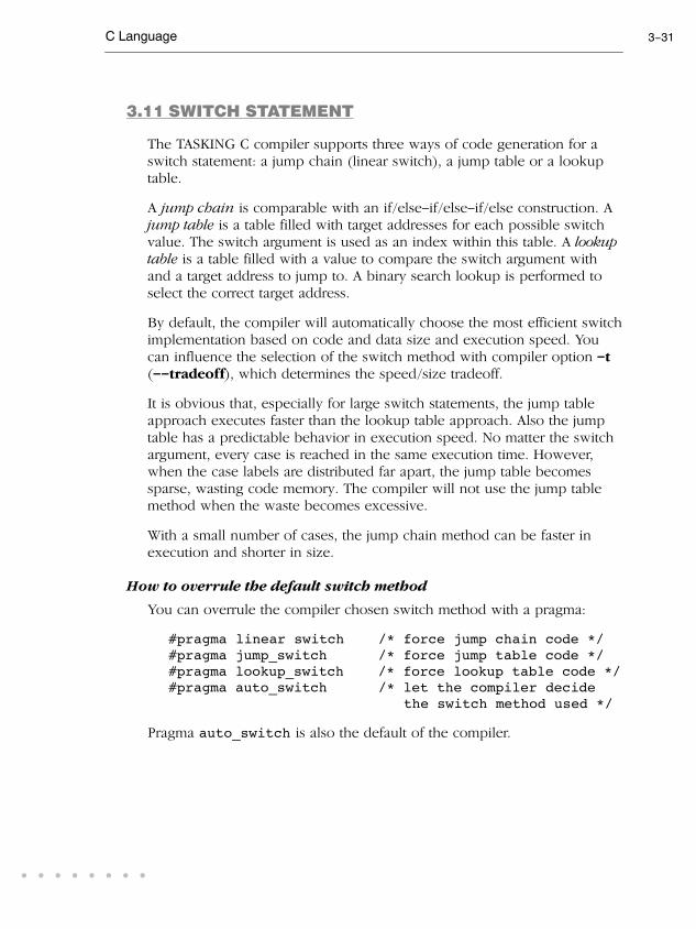
C Language 3-31
• • • • • • • •
3.11 SWITCH STATEMENT
The TASKING C compiler supports three ways of code generation for a
switch statement: a jump chain (linear switch), a jump table or a lookup
table.
A jump chain is comparable with an if/else-if/else-if/else construction. A
jump table is a table filled with target addresses for each possible switch
value. The switch argument is used as an index within this table. A lookuptable is a table filled with a value to compare the switch argument with
and a target address to jump to. A binary search lookup is performed to
select the correct target address.
By default, the compiler will automatically choose the most efficient switch
implementation based on code and data size and execution speed. You
can influence the selection of the switch method with compiler option -t
(--tradeoff), which determines the speed/size tradeoff.
It is obvious that, especially for large switch statements, the jump table
approach executes faster than the lookup table approach. Also the jump
table has a predictable behavior in execution speed. No matter the switch
argument, every case is reached in the same execution time. However,
when the case labels are distributed far apart, the jump table becomes
sparse, wasting code memory. The compiler will not use the jump table
method when the waste becomes excessive.
With a small number of cases, the jump chain method can be faster in
execution and shorter in size.
How to overrule the default switch method
You can overrule the compiler chosen switch method with a pragma:
#pragma linear switch /* force jump chain code */
#pragma jump_switch /* force jump table code */
#pragma lookup_switch /* force lookup table code */
#pragma auto_switch /* let the compiler decide
the switch method used */
Pragma auto_switch is also the default of the compiler.

User's Manual3-32C
LA
NG
UA
GE
3.12 FUNCTIONS
3.12.1 PARAMETER PASSING
A lot of execution time of an application is spent transferring parameters
between functions. The fastest parameter transport is via registers.
Therefore, function parameters are first passed via registers. If no more
registers are available for a parameter, the parameter is passed via the
stack. The table below shows the register usage when parameters of
several types are passed.
Parameter Type Parameter Number
1 2 3 4 5 .. 16
__bit / _Bool 0,R0 1,R0 2,R0 3,R0 4,R0 .. 15,R0
char R0L R0H
8-bit struct R0L R0H
short / int R0 R2 R1 R3
16-bit struct R0 R2 R1 R3
16-bit pointer A0 A1
32-bit pointer A1A0
long R2R0 R3R1
long long R3R1R2R0
float /
float _Imaginary
R2R0 R3R1
float _Complex R3R1R2R0
double /
double _Imaginary
R3R1R2R0
Table 3-7: Register usage for parameter passing
All '...' parameters of a variable argument list function are always passed
over the stack. Parameters are pushed in reverse order, so all ISO C
macros defined in stdarg.h can be applied.

C Language 3-33
• • • • • • • •
Example with five arguments
func1( char a, long b, long c, int d, char e )
- a (first parameter) is passed in register R0L
- b (second parameter) is passed in registers R3R1
- c (third parameter) is passed via the stack
- d (fourth parameter) is passed in register R2
- e (fifth parameter) is passed in register R0H
Example with variable argument function
printf( char *format, ... )
- format (first parameter) is passed in register A0
- all other parameters are passed via the stack
3.12.2 FUNCTION RETURN TYPES
The C compiler uses registers to store C function return values, depending
on the function return types.
Return type Register
__bit / _Bool C
char R0L
8-bit struct R0L
short / int R0
16-bit struct R0
16-bit pointer A0
32-bit pointer A1A0
long R2R0
long long R3R1R2R0
float /
float _Imaginary
R2R0
float _Complex R3R1R2R0
double /
double _Imaginary
R3R1R2R0
double _Complex on the stack
Table 3-8: Register usage for function return types

User's Manual3-34C
LA
NG
UA
GE
3.12.3 INLINING FUNCTIONS: INLINE
You can use the inline keyword to tell the compiler to inline the
function body instead of calling the function. Use the __noinline
keyword to tell the compiler not to inline the function body.
Normally, you must define inline functions in the same source module as
in which you call the function, because the compiler only inlines a
function in the module that contains the function definition. When you
need to call the inline function from several source modules, you must:
• include the definition of the inline function in each module (for
example using an include file containing the definition).
• enable MIL linking on the Optimizations page of the C compiler
options and compile the involved files in the same run.
The compiler inserts the function body at the place the function is called.
If the function is not called at all, the compiler does not generate code for
it.
Example: inline
int w,x,y,z;
inline int add( int a, int b )
{
return( a + b );
}
void main( void )
{
w = add( 1, 2 );
z = add( x, y );
}
The function add() is defined before it is called. The compiler inserts
(optimized) code for both calls to the add() function. The generated
assembly is:

C Language 3-35
• • • • • • • •
_main:
mov.w #3, _w
mov.w _y, A0
add.w _x, A0
mov.w A0, _z
Example: #pragma inline / #pragma noinline
Instead of the inline qualifier, you can also use #pragma inline and
#pragma noinline to inline a function body:
int w,x,y,z;
#pragma inline
int add( int a, int b )
{
return( a + b );
}
#pragma noinline
void main( void )
{
w = add( 1, 2 );
z = add( x, y );
}
If a function has an inline/__noinline function qualifier, then this
qualifier will overrule the current pragma setting.
#pragma smartinline
By default, small fuctions that are not too often called, are inlined. This
reduces execution time at the cost of code size (compiler option -Oi).
With the #pragma noinline / #pragma smartinline you can
temporarily disable this optimization.
With the compiler options --inline-max-incr and --inline-max-size
you have more control over the function inlining process of the compiler.
See for more information of these options, section Compiler Options inChapter Tool Options of the Reference Manual.

User's Manual3-36C
LA
NG
UA
GE
Combining inline with __asm to create intrinsic functions
With the keyword __asm it is possible to use assembly instructions in the
body of an inline function. Because the compiler inserts the (assembly)
body at the place the function is called, you can create your own intrinsic
function.
See section 3.6, Using Assembly in the C Source, for more information
about the __asm keyword.
Example 6 in that section shows how to inline assembly functions with the
inline keyword.
3.12.4 INTRINSIC FUNCTIONS
Some specific M16C assembly instructions have no equivalence in C.
Intrinsic functions give the possibility to use these instructions. Intrinsic
functions are predefined functions that are recognized by the compiler.
The compiler then generates the most efficient assembly code for these
functions.
The compiler always inlines the corresponding assembly instructions in the
assembly source rather than calling the function. This avoids unnecessary
parameter passing and register saving instructions which are normally
necessary when a function is called.
Intrinsic functions produce very efficient assembly code. Though it is
possible to inline assembly code by hand, registers are used even more
efficient by intrinsic functions. At the same time your C source remains
very readable. Intrinsic functions do not limit the optimization possibilities
of the compiler opposed to assembly that is hand coded with __asm.
You can use intrinsic functions in C as if they were ordinary C (library)
functions. All intrinsics begin with a double underscore character. The
following example illustrates the use of an intrinsic function and its
resulting assembly code.
char q;
q = __divb_q( 10,3 ); // return quotient of divide
The resulting assembly code is inlined rather than being called:
mov.w #10, R0
div.b #3
mov.b R0L, _q

C Language 3-37
• • • • • • • •
For extended information about all available intrinsic functions, refer to
section 1.5, Intrinsic Functions, in Chapter C Language of the ReferenceManual.
3.12.5 CALLING ASSEMBLY FUNCTIONS: __asmfunc
For a fixed register-based interface between C and assembly functions the
function qualifier __asmfunc is available. You can use this function
qualifier for a prototype of an assembly function to be called from C or for
a function definition of a C function to be called from assembly. Normally,
the C compiler adds a leading underscore when it generates an assembly
function, with __asmfunc the C compiler does not add the extra
underscore.
Example:
/* prototype of assembly function */
extern __asmfunc int
special_out( int port, long config, int value );
void main( void )
{
long cfg;
int y;
...
if( special_out( 1, cfg, y ) ) /* call assembly
function */
{
...
}
...
}
The number of arguments that can be passed is limited by the number of
available registers. (See section 3.12.1, Parameter Passing. If too many
arguments are used, the compiler will issue an error.

User's Manual3-38C
LA
NG
UA
GE
3.12.6 INTERRUPT FUNCTIONS
The TASKING M16C C compiler supports a number of function qualifiers
and keywords to program interrupt service routines (ISR).
An interrupt service routine (or: interrupt function, or: interrupt handler) is
called when an interrupt event (or: service request) occurs. This can be a
software interrupt or a hardware interrupt.
A software interrupt occurs when certain instructions are executed.
Software interrupt are non-maskable, which means that the interrupt
cannot be enable or disabled by the interrupt enable flag (I flag) or that its
interrupt priority cannot be changed by priority level.
A hardware interrupt can be a special (non-maskable) interrupt, for
example an interrupt triggered by a watchdog timer, or a peripheral
function interrupt generated by a microcomputer's internal function.
Peripheral function interrupts are maskable, which means that the interrupt
can be enable or disabled by the interrupt enable flag (I flag) or that its
interrupt priority can be changed by priority level.
Each maskable interrupt has an interrupt priority level. This number (0 to
7) is set in the interrupt control register (xxxIC) by the interrupt control
unit. If multiple interrupts occur at the same time, the interrupt request that
has the highest priority is accepted. A request is handled if the priority
number is higher than the processor interrupt priority level (IPL). An
interrupt service routine can be interrupted again by another interrupt
request with a higher priority. Interrupts with priority number 0 are never
handled.
The M16C uses two interrupt vector tables for the hardware and software
interrupts: a relocatable vector table and a fixed vector table. The interrupt
vector contains the start address of the interrupt service routine.
With the following function qualifiers you can declare an interrupt handler
using the relocatable or fixed vector table respectively:
__interrupt()
__interrupt_fixed()
For an extensive description of the M16C interrupt system, see chapter
Overview of Interrupt in the M16C Group Specification [Renesas]

C Language 3-39
• • • • • • • •
3.12.6.1 DEFINING AN INTERRUPT SERVICE ROUTINE:
__interrupt()
A function can be declared as an interrupt service routine with one of the
following function qualifiers:
__interrupt(vector,...)
__interrupt_fixed(vector,...)
Both function qualifiers takes vector as an argument which identifies the
interrupt number entry in the interrupt vector table. This number must be
in the range 0 to 63 for __interrupt() or 0 to 8 for
__interrupt_fixed(). Interrupt functions cannot accept arguments and
do not return anything.
For the relocatable vector table use:
__interrupt( vector,... )
void isr( void )
{ ... }
For the fixed vector table use:
__interrupt_fixed( vector,... )
void isr( void )
{ ... }
When you define an interupt service routine, the compiler generates the
appropriate interrupt vector, consisting of an instruction jumping to the
interrupt function. You can suppress this with the compiler option
--novector or the #pragma novector. The difference between a normal
function and an interrupt function is that an interrupt function ends with a
RETI instruction instead of a RET instruction, and that all registers that
might possibly be corrupted during the execution of the interrupt function
are saved on function entry (this is called the interrupt frame) and restored
on function exit.

User's Manual3-40C
LA
NG
UA
GE
Example
The next example illustrates the function definition for a function for a
software interrupt with vector number 0x30 in the relocatable vector table:
int c;
void __interrupt( 0x30 ) transmit( void )
{
c = 1;
}
Compiler option --novector (Do not generate interrupt vectors)
3.12.6.2 REGISTER BANK SWITCHING: __bankswitch
Normally when an interrupt function is called, all registers that might
possibly be corrupted during the execution of the interrupt function are
saved on the stack so the registers are available for the interrupt function.
After return from thrrupt function the original values are restored from the
stack.
With the function qualifier __bankswitch you can specify to use register
bank 1 for the interrupt function. This minimizes the interrupt latency
because registers do not need to be pushed on the stack. You can use this
to reduce time for high-speed interrupt handling.
__interrupt( vector,... ) __bankswitch
void isr( void )
{
...
}
__interrupt_fixed( vector,... ) __bankswitch
void isr( void )
{
...
}

C Language 3-41
• • • • • • • •
3.12.6.3 INTERRUPT FRAME: __frame()
With the function qualifier __frame() you can specify which registers
must be saved for a particular interrupt function. Only the specified
registers will be pushed and popped from the stack. The syntax is:
__interrupt( vector,... ) __frame( reg,... )
void isr( void )
{
...
}
__interrupt_fixed( vector,... ) __frame( reg,... )
void isr( void )
{
...
}
where, reg can be one of the following registers: R0..R3, A0, A1, FB or SB.
If you do not specify the function qualifier __frame(), the C compiler
determines which registers must be pushed and popped.
Example
__interrupt(1) __frame(R0,R1)
void alarm( void )
{
/* an interrupt function */
}
When you do not want the interrupt frame (saving/restoring registers) to
be generated you can use the compiler option --noframe. In that case
you will have to specify your own interrupt frame. For this you can use
the inline capabilities of the compiler.
Compiler option --noframe (Do not generate frame for interrupt handler)
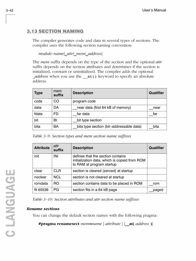
User's Manual3-42C
LA
NG
UA
GE
3.13 SECTION NAMING
The compiler generates code and data in several types of sections. The
compiler uses the following section naming convention:
module-name[_attr]_mem[_address]
The mem suffix depends on the type of the section and the optional attrsuffix depends on the section attributes and determines if the section is
initialized, constant or uninitialized. The compiler adds the optional
_address when you use the __at() keyword to specify an absolute
address.
Typememsuffix
Description Qualifier
code CO program code
data DA __near data (first 64 kB of memory) __near
fdata FD __far data __far
bit BI __bit type section
bita BA __bita type section (bit-addressable data) __bita
Table 3-9: Section types and mem section name suffixes
Attributeattr suffix
Description Qualifier
init INI defines that the section contains
initialization data, which is copied from ROM
to RAM at program startup
clear CLR section is cleared (zeroed) at startup
noclear NCL section is not cleared at startup
romdata RO section contains data to be placed in ROM __rom
fit 65536 PG section fits in a 64 kB page __paged
Table 3-10: Section attributes and attr section name suffixes
Rename sections
You can change the default section names with the following pragma:
#pragma renamesect mem=name [ attribute ] [__at( address )]

C Language 3-43
• • • • • • • •
The new name replaces the module-name part of the section names that
have type mem. With the optional attribute you can overrule the section
attribute. With the optional __at() keyword you can place a section at an
absolute address.
For example,
#pragma renamesect DA=flash clear __at(0x20)
All sections of type 'data' have the name "flash_attr_DA" and have
attribute 'clear' and 'at 0x20'.
The following pragma restores the default section naming for type mem.
#pragma endrenamesect mem
See also compiler option -R in section Compiler Options in Chapter ToolOptions of the Reference Manual.
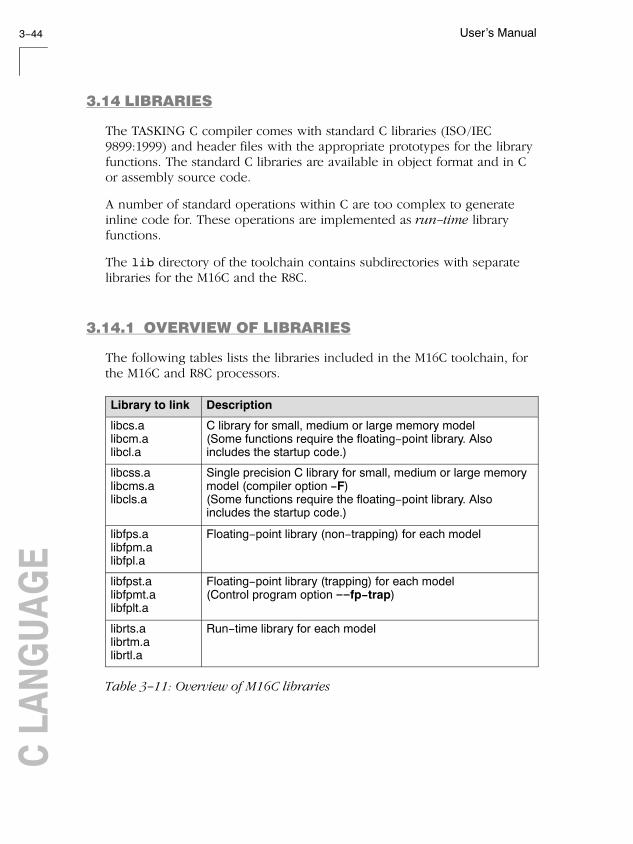
User's Manual3-44C
LA
NG
UA
GE
3.14 LIBRARIES
The TASKING C compiler comes with standard C libraries (ISO/IEC
9899:1999) and header files with the appropriate prototypes for the library
functions. The standard C libraries are available in object format and in C
or assembly source code.
A number of standard operations within C are too complex to generate
inline code for. These operations are implemented as run-time library
functions.
The lib directory of the toolchain contains subdirectories with separate
libraries for the M16C and the R8C.
3.14.1 OVERVIEW OF LIBRARIES
The following tables lists the libraries included in the M16C toolchain, for
the M16C and R8C processors.
Library to link Description
libcs.a
libcm.a
libcl.a
C library for small, medium or large memory model
(Some functions require the floating-point library. Also
includes the startup code.)
libcss.a
libcms.a
libcls.a
Single precision C library for small, medium or large memory
model (compiler option -F)
(Some functions require the floating-point library. Also
includes the startup code.)
libfps.a
libfpm.a
libfpl.a
Floating-point library (non-trapping) for each model
libfpst.a
libfpmt.a
libfplt.a
Floating-point library (trapping) for each model
(Control program option --fp-trap)
librts.a
librtm.a
librtl.a
Run-time library for each model
Table 3-11: Overview of M16C libraries

C Language 3-45
• • • • • • • •
Library to link Description
libc.a C library
(Some functions require the floating-point library. Also
includes the startup code.)
libcs.a Single precision C library (compiler option -F)
(Some functions require the floating-point library. Also
includes the startup code.)
libfp.a Floating-point library (non-trapping)
libfpt.a Floating-point library (trapping)
(Control program option --fp-trap)
librt.a Run-time library
Table 3-12: Overview of R8C libraries
See section 2.2, Library Functions, in Chapter Libraries of the ReferenceManual for an extensive description of all standard C library functions.
3.14.2 PRINTF AND SCANF FORMATTING ROUTINES
The C library functions printf(), fprintf(), vfprintf(),
vsprintf(), ... call one single function, _doprint(), that deals with the
format string and arguments. The same applies to all scanf type functions,
which call the function _doscan(), and also for the wprintf and
wscanf type functions which call _dowprint() and _dowscan()
respectively. The C library contains three versions of these routines: int,
long and long long versions. If you use floating-point, the formatter
function for floating-point _doflt() or _dowflt() is called. Depending
on the formatting arguments you use, the correct routine is used from the
library. Of course the larger the version of the routine the larger your
produced code will be.
Note that when you call any of the printf/scanf routines indirect, the
arguments are not known and always the long long version with
floating-point support is used from the library.

User's Manual3-46C
LA
NG
UA
GE
Example:
#include <stdio.h>
long L;
void main(void)
{
printf( "This is a long: %ld\n", L );
}
The linker extracts the long version without floating-point support from
the library.
3.14.3 REBUILDING LIBRARIES
If you have manually changed one of the standard C library functions, you
need to recompile the standard C libraries.
'Weak' symbols are used to extract the most optimal implementation of a
function from the library. For example if your application does not use
floating-point variables the prinf alike functions do not support
floating-point types either. The compiler emits strong symbols to guide
this process. Do not change the order in which modules are placed in the
library since this may break this process.
The sources of the libraries are present in the lib\src directory. This
directory also contains subdirectories with a makefile for each type of
library:
lib\src\
m16c\
libcl\makefile
libcm\makefile
libcs\makefile
librtl\makefile
librtm\makefile
librts\makefile
r8c\
libc\makefile
librt\makefile
To rebuild the libraries, follow the next steps.

C Language 3-47
• • • • • • • •
First make sure that the bin directory for the toolchain is included in your
PATH environment variable. (See section 1.3.2, Configuring the CommandLine Environment.
1. Make the directory lib\src\m16c\libcl the current working
directory.
This directory contains a makefile which also uses the default makerules from mkm16c.mk from the cm16c\etc directory.
2. Edit the makefile.
See section 9.3, Make Utility, in Chapter Utilities for an extensive
description of the make utility and makefiles.
3. Assuming the lib\src\m16c\libcl directory is still the current
working directory, type:
mkm16c
to build the library.
The new library is created in the lib\src\m16c\libcl directory.
4. Make a backup copy of the original library and copy the new library to
the lib\m16c directory of the product.
3.15 CONVERTING C MODULES TO ISO C99
The TASKING M16C C compiler fully supports the ISO/IEC 9899:1999(E)
standard. V2.3 and older C source files may not meet the requirements of
the ISO C99 standard. However, EDE provides an option to convert these
files automatically.
To convert one or more C source files:
1. Click on the Convert C modules to the ISO-C style button.
The Conversion dialog box appears.

User's Manual3-48C
LA
NG
UA
GE
2. Select whether you want to convert All C files in project or the Current
selected file.
3. Enable or disable the options Prompt before replace and Insert
comment with each replacement.
If you select comments, you can format the comments to be inserted.
4. Type a format string in the comment field.
For example, to insert C++ style comments with a date, type:
// 2004 1 (where 1 is replaced with the standard replacement message).
5. Click OK to start the conversion.
During conversion the following will be changed:
• M16C keywords with a single underscore are replaced with keywords
with double underscore. For example, replace _bit with __bit.
• Old predefined macro names are replaced with new macro names. For
example, replace _MODEL with __MODEL__.
• Pragmas are replaced, removed or commented because their meaning
has changed. For example, replace #pragma asm/endasm part with
__asm keyword.
• M16C intrinsic functions with a single underscore are replaced with
intrinsic functions with double underscore. For example, replace
_absb with __absb.

4
ASSEMBLY
LANGUAGEC
HA
PT
ER

User's Manual4-2A
SS
EM
BLY
LA
NG
UA
GE
4
CH
AP
TE
R

Assembly Language 4-3
• • • • • • • •
4.1 INTRODUCTION
This chapter describes the most important aspects of the M16C assembly
language. For a complete overview of the M16C assembly language, refer
to the M16C Series Software Manual [Renesas].
4.2 ASSEMBLY SYNTAX
An assembly program consists of zero or more statements. A statement
may optionally be followed by a comment. Any source statement can be
extended to more lines by including the line continuation character (\) as
the last character on the line. The length of a source statement (first line
and continuation lines) is only limited by the amount of available memory.
Mnemonics and directives are case insensitive. Labels, symbols, directive
arguments, and literal strings are case sensitive.
The syntax of an assembly statement is:
[label[:]] [instruction | directive | macro_call] [;comment]
label A label is a special symbol which is assigned the value and
type of the current program location counter. A label can
consist of letters, digits and underscore characters (_). The
first character cannot be a digit. A label which is prefixed by
whitespace (spaces or tabs) has to be followed by a colon (:).
The size of an identifier is only limited by the amount of
available memory.
Examples:
LAB1: ; This label is followed by a colon and
can be prefixed by whitespace
LAB1 ; This label has to start at the beginning
of a line

User's Manual4-4A
SS
EM
BLY
LA
NG
UA
GE
instruction An instruction consists of a mnemonic and zero, one or more
operands. It must not start in the first column. Operands are
described in section 4.4, Operands of an AssemblyInstruction. The instructions are described in the M16C SeriesSoftware Manual [Renesas].
Examples:
REIT ; No operand
PUSH.W R0 ; One operand
ADD.W R0,R1 ; Two operands
STZX #12,#22,15[FB] ; Three operands
directive With directives you can control the assembler from within the
assembly source. These must not start in the first column.
Directives are described in section 4.8, Assembler Directivesand Controls.
macro_call A call to a previously defined macro. It must not start in the
first column. Macros are described in section 4.10 MacroOperations.
You can use empty lines or lines with only comments.
Apart from the assembly statements as described above, you can put a
so-called 'control line' in your assembly source file. These lines start with
a $ in the first column and alter the default behavior of the assembler.
$control
For more information on controls see section 4.8, Assembler Directives andControls.
4.3 ASSEMBLER SIGNIFICANT CHARACTERS
You can use all ASCII characters in the assembly source both in strings and
in comments. Also the extended characters from the ISO 8859-1 (Latin-1)
set are allowed.
Some characters have a special meaning to the assembler. Special
characters associated with expression evaluation are described in section
4.6.3, Expression Operators. Other special assembler characters are:

Assembly Language 4-5
• • • • • • • •
Character Description
; Start of a comment
\ Line continuation character or
Macro operator: argument concatenation
? Macro operator: return decimal value of a symbol
% Macro operator: return hex value of a symbol
^ Macro operator: override local label
" Macro string delimiter or
Quoted string DEFINE expansion character
' String constants delimiter
@ Start of a built-in assembly function
$ Location counter substitution
# Constant number (immediate addressing mode)
++ String concatenation operator
[ ] Substring delimiter or
Indirect addressing mode operator
Note that macro operators have a higher precedence than expression
operators.
4.4 OPERANDS OF AN ASSEMBLY INSTRUCTION
In an instruction, the mnemonic is followed by zero, one or more
operands. An operand has one of the following types:
Operand Description
symbol A symbolic name as described in section 4.5, SymbolNames. Symbols can also occur in expressions.
register Any valid data register (R0, R0H, R0L, R1, R1H, R1L, R2,
R3), address register (A0, A1), frame base register (FB),
static base register (SB), control register (PC, INTB, USP,
ISP, FLG) or special function register. For some instruction
you can use a register pair (R2R0, R3R1, A1A0).
expression Any valid expression as described in the section 4.6,
Assembly Expressions.
address A combination of expression, register and symbol.

User's Manual4-6A
SS
EM
BLY
LA
NG
UA
GE
The M16C assembly language has several addressing modes. These
described in detail in the M16C Series Software Manual [Renesas].
4.5 SYMBOL NAMES
User-defined symbols
A user-defined symbol can consist of letters, digits and underscore
characters (_). The first character cannot be a digit. The size of an
identifier is only limited by the amount of available memory. The case of
these characters is significant. You can define a symbol by means of a
label declaration or an equate or set directive.
Labels
Symbols used for memory locations are referred to as labels.
Reserved symbols
Register names and names of assembler directives and controls are
reserved for the system, so you cannot use these for user-defined symbols.
The case of these built-in symbols is insignificant.
Examples
CON1 EQU 3H ; The symbol CON1 represents
; the value of 3 hex
MOV.W CON1 + 020H, R1 ; Move contents of address
; 023H to register R1
Valid symbol names Invalid symbol names
loop_1
ENTRY
a_B_c
_aBC
1_loop (starts with a number)R0 (reserved register name)DEFINE (reserved directive name)

Assembly Language 4-7
• • • • • • • •
4.6 ASSEMBLY EXPRESSIONS
An expression is a combination of symbols, constants, operators, and
parentheses which represent a value that is used as an operand of an
assembler instruction (or directive).
Expressions can contain user-defined labels (and their associated integer
or floating-point values), and any combination of integers, floating-point
numbers, or ASCII literal strings.
Expressions follow the conventional rules of algebra and boolean
arithmetic.
Expressions that can be evaluated at assembly time are called absoluteexpressions. Expressions where the result is unknown until all sections
have been combined and located, are called relocatable or relativeexpressions.
When any operand of an expression is relocatable, the entire expression is
relocatable. Relocatable expressions are emitted in the object file and are
evaluated by the linker. Relocatable expressions can only contain integral
functions; floating-point functions and numbers are not supported by the
ELF/DWARF object format.
The assembler evaluates expressions with 64-bit precision in two's
complement.
An expression can be any of the following:
- numeric contant
- string
- symbol
- expression binary_operator expression
- unary_operator expression
- ( expression )
- function call
All types of expressions are explained in separate sections.

User's Manual4-8A
SS
EM
BLY
LA
NG
UA
GE
4.6.1 NUMERIC CONSTANTS
Numeric constants can be used in expressions. If there is no prefix, the
assembler assumes the number is a decimal number.
Base Description Example
Binary '0B' or '0b' followed by binary digits (0,1).0B1101
0b11001010
Hexadecimal'0X' or '0x' followed by a hexadecimal
digits (0-9, A-F, a-f).
0X12FF
0x45
0x9abc
Decimal,
integerDecimal digits (0-9).
12
1245
Decimal,
floating point
Includes a decimal point, or an 'E' or 'e'
followed by the exponent.
6E10
.6
3.14
2.7e10
4.6.2 STRINGS
ASCII characters, enclosed in single (') or double (″) quotes constitue an
ASCII string. Strings between double quotes allow symbol substitution by a
DEFINE directive, whereas strings between single quotes are always literal
strings. Both types of strings can contain escape characters.
Strings constants in expressions are evaluated to a number (each character
is replaced by its ASCII value). Strings in expressions can have a size of up
to a long word (first 4 characters) or less depending on the operand of an
instruction or directive; any subsequent characters in the string are
ignored. In this case the assembler issues a warning. An exception to this
rule is when a string longer than 4 characters is used in a DB assembler
directive; in that case all characters result in a constant byte. Null strings
have a value of 0.
Square brackets ([ ]) delimit a substring operation in the form:
[string,offset,length]
offset is the start position within string. length is the length of the desired
substring. Both values may not exceed the size of string.

Assembly Language 4-9
• • • • • • • •
Examples
'ABCD' ; (0x41424344)
'''79' ; to enclose a quote double it
"A\"BC" ; or to enclose a quote escape it
'AB'+1 ; (0x4143) string used in expression
'' ; null string
dl 'abcdef' ; (0x61626364) 'ef' are ignored
; warning: string value truncated
'ab'++'cd' ; you can concatenate two strings
; with the '++' operator.
; This results in 'abcd'
['TASKING',0,4] ; results in the substring 'TASK'
4.6.3 EXPRESSION OPERATORS
The next table shows the assembler operators. They are ordered according
to their precedence. Operators of the same precedence are evaluated left
to right. Expressions between parentheses have the highest priority
(innermost first).
Valid operands include numeric constants, literal ASCII strings and
symbols.
Most assembler operators can be used with both integer and floating-point
values. If one operand has an integer value and the other operand has a
floating-point value, the integer is converted to a floating-point value
before the operator is applied. The result is a floating-point value.
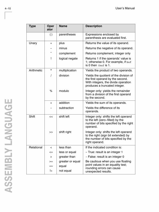
User's Manual4-10A
SS
EM
BLY
LA
NG
UA
GE
Type Operator
Name Description
( ) parentheses Expressions enclosed by
parenthesis are evaluated first.
Unary + plus Returns the value of its operand.
- minus Returns the negative of its operand.
~ complement Returns complement, integer only
! logical negate Returns 1 if the operands' value is
1; otherwise 0. For example, if buf
is 0 then !buf is 1.
Arithmetic * multiplication Yields the product of two operands.
/ division Yields the quotient of the division of
the first operand by the second.
With integers, the divide operation
produces a truncated integer.
% modulo Integer only: yields the remainder
from a division of the first operand
by the second.
+ addition Yields the sum of its operands.
- subtraction Yields the difference of its
operands.
Shift << shift left Integer only: shifts the left operand
to the left (zero-filled) by the
number of bits specified by the right
operand.
>> shift right Integer only: shifts the left operand
to the right (sign bit extended) by
the number of bits specified by the
right operand.
Relational <
<=
>
>=
==
!=
less than
less or equal
greater than
greater or equal
equal
not equal
If the indicated condition is:
- True: result is an integer 1
- False: result is an integer 0
Be cautious when you use floating
point values in an equality test;
rounding errors can cause
unexpected results.

Assembly Language 4-11
• • • • • • • •
DescriptionNameOperator
Type
Bitwise & AND Integer only: yields bitwise AND
| OR Integer only: yields bitwise OR
^ exclusive OR Integer only: yields bitwise exlusive
OR
Logical && logical AND Returns an integer 1 if both
operands are nonzero; otherwise, it
returns an integer 0.
|| logical OR Returns an integer 1 if either of the
operands is nonzero; otherwise, it
returns an integer 1
Table 4-1: Assembly expression operators
4.7 BUILT-IN ASSEMBLY FUNCTIONS
The assembler has several built-in functions to support data conversion,
string comparison, and math computations. You can use functions as terms
in any expression. Functions have the following syntax:
Syntax of an assembly function
@function_name([argument[,argument]...])
Functions start with the '@' character and have zero or more arguments,
and are always followed by opening and closing parentheses. White space
(a blank or tab) is not allowed between the function name and the
opening parenthesis and between the (comma-separated) arguments.
The built-in assembler functions are grouped into the following types:
• Mathematical functions comprise, among others, transcendental,
random value, and min/max functions.
• String functions compare strings, return the length of a string, and
return the position of a substring within a string.
• Macro functions return information about macros.
• Address calculation functions return the high or low part of an
address.
• Assembler mode functions relating assembler operation.

User's Manual4-12A
SS
EM
BLY
LA
NG
UA
GE
The following tables provide an overview of all built-in assembler
functions. For a detailed description of these functions, see section 3.2,
Built-in Assembly Function, in Chapter Assembly Language of the
Reference Manual.
Overview of mathematical functions
Function Description
@ABS(expr) Absolute value
@MAX(expr,[,...,exprN]) Maximum value
@MIN(expr,[,...,exprN]) Minimum value
@SGN(expr) Returns the sign of an expression as -1, 0 or 1
Overview of string functions
Function Description
@CAT(str1,str2) Concatenate strings
@LEN(string) Length of string
@POS(str1,str2[,start]) Position of substring in string
@SCP(str1,str2) Returns 1 if two strings are equal
@SUB(string,expr,expr) Returns substring in string
Overview of macro functions
Function Description
@ARG('symbol'|expr) Test if macro argument is present
@CNT() Return number of macro arguments
@MAC(symbol) Test if symbol is defined as a macro
@MXP() Test if macro expansion is active
Overview of address calculation functions
Function Description
@LSW(expr) Returns lower 16 bits of expression value
@MSW(expr) Returns bits 16..31 of expression value
Assembly Language 4-13
• • • • • • • •
Overview of assembler mode functions
Function Description
@DEF('symbol'|symbol) Returns 1 if symbol has been defined
@LST() LIST control flag value
4.8 ASSEMBLER DIRECTIVES AND CONTROLS
An assembler directive is simply a message to the assembler. Assembler
directives are not translated into machine instructions. There are three
main groups of assembler directives.
• Assembler directives that tell the assembler how to go about translating
instructions into machine code. This is the most typical form of
assembly directives. Typically they tell the assembler where to put a
program in memory, what space to allocate for variables, and allow
you to initialize memory with data. When the assembly source is
assembled, a location counter in the assembler keeps track of where
the code and data is to go in memory.
The following directives fall under this group:
- Assembly control directives
- Symbol definition directives
- Data definition / Storage allocation directives
- Debug directives
• Directives that are interpreted by the macro preprocessor. These
directives tell the macro preprocessor how to manipulate your
assembly code before it is actually being assembled. You can use these
directives to write macros and to write conditional source code. Parts of
the code that do not match the condition, will not be assembled at all.
• Some directives act as assembler options and most of them indeed do
have an equivalent assembler (command line) option. The advantage
of using a directive is that with such a directive you can overrule the
assembler option for a particular part of the code. Directives of this
kind are called controls. A typical example is to tell the assembler with
an option to generate a list file while with the controls $LIST ON and
$LIST OFF you overrule this option for a part of the code that you do
not want to appear in the list file. Controls always appear on a separate
line and start with a '$' sign in the first column.

User's Manual4-14A
SS
EM
BLY
LA
NG
UA
GE
The following controls are available:
- Assembly listing controls
- Miscellaneous controls
Each assembler directive or control has its own syntax. You can use
assembler directives and controls in the assembly code as pseudo
instructions.
4.8.1 OVERVIEW OF ASSEMBLER DIRECTIVES
The following tables provide an overview of all assembler directives. For a
detailed description, see section 3.3.2, Detailed Description of AssemblerDirectives, in Chapter Assembly Language of the Reference Manual.
Overview of assembly control directives
Directive Description
COMMENT Start comment lines. You cannot use this directive in
IF/ELSE/ENDIF constructs and MACRO/DUP
definitions.
DEFINE Define substitution string
DEFSECT Define section name, type and attributes
END End of source program
FAIL Programmer generated error message
INCLUDE Include file
MSG Programmer generated message
RADIX Change input radix for constants
SECT Activate a declared section
UNDEF Undefine DEFINE symbol
WARN Programmer generated warning

Assembly Language 4-15
• • • • • • • •
Overview of symbol definition directives
Directive Description
BTEQU Bit equate
EQU Assigns permanent value to a symbol
EXTERN External symbol declaration
GLOBAL Global symbol declaration
LOCAL Local symbol declaration
SET Set temporary value to a symbol
SIZE Set size of symbol in the ELF symbol table
TYPE Set symbol type in the ELF symbol table
WEAK Mark symbol as 'weak'
Overview of data definition / storage allocation directives
Directive Description
ALIGN Define alignment
ASCII / ASCIZ Define ASCII string without / with ending NULL byte
BS Define block storage (initialized)
BSB Define byte block storage (initialized)
BSBIT Define bit block storage in bit-addressable data
BSW / BSL Define word / long block storage (initialized)
DB Define constant byte
DBIT Define constant bit
DS Define storage
DW / DL Define a word / long constant
FLOAT / DOUBLE Define a float / double constant

User's Manual4-16A
SS
EM
BLY
LA
NG
UA
GE
Overview of macro and conditional assembly directives
Directive Description
DUP Duplicate sequence of source lines
DUPA Duplicate sequence with arguments
DUPC Duplicate sequence with characters
DUPF Duplicate sequence in loop
ENDM End of macro or duplicate sequence
EXITM Exit macro
IF/ELIF/ELSE/ENDIF Conditional assembly
MACRO Define macro
PMACRO Undefine (purge) macro
Overview of debug directives
Directive Description
CALLS Passes call information to object file. Used by the
linker to build a call graph and calculate stack size
4.8.2 OVERVIEW OF ASSEMBLER CONTROLS
The following tables provide an overview of all assembler controls. For a
detailed description, see section 3.3.4, Detailed Description of AssemblerControls, in Chapter Assembly Language of the Reference Manual.
Overview of assembly listing controls
Control Description
$LIST ON/OFF Generation of assembly list file temporary ON/OFF
$LIST "flags" Exclude / include lines in assembly list file
$PAGE Generate formfeed in assembly list file
$PAGE settings Define page layout for assemly list file
$PRCTL Send control string to printer
$STITLE string Set program subtitle in header of assembly list file
$TITLE string Set program title in headerof assembly list file

Assembly Language 4-17
• • • • • • • •
Overview of miscellaneous assembler controls
Control Description
$CASE ON/OFF Case sensitive user names ON/OFF
$DEBUG ON/OFF Generation of symbolic debug ON/OFF
$DEBUG "flags" Generation of symbolic debug ON/OFF
$IDENT
LOCAL/GLOBAL
Assembler treats labels by default as local or global
$OBJECT Alternative name for the generated object file
$OPTJ ON/OFF Turn on/off conditional optimization
$WARNING OFF [num] Suppress one or all warnings
4.9 WORKING WITH SECTIONS
Sections are absolute or relocatable blocks of contiguous memory that can
contain code or data. Some sections contain code or data that your
program declared and uses directly, while other sections are created by
the compiler or linker and contain debug information or code or data to
initialize your application. These sections can be named in such a way that
different modules can implement different parts of these sections. These
sections are located in memory by the linker (using the linker script
language, LSL) so that concerns about memory placement are postponed
until after the assembly process.
All instructions and directives which generate data or code must be within
an active section. The assembler emits a warning if code or data starts
without a section definition and activation. The compiler automatically
generates sections. If you program in assembly you have to define sections
yourself.
For more information about locating sections see section 8.6.7 The SectionLayout Definition: Locating Sections in chapter Using the Linker.
Section definition
Sections are defined with the DEFSECT directive and have a name. A
section may have attributes to instruct the linker to place it on a
predefined starting address, or that it may be overlaid with another
section.
DEFSECT "name", type [, attribute ]... [AT address]

User's Manual4-18A
SS
EM
BLY
LA
NG
UA
GE
See the DEFSECT directive in section 3.3.2, Detailed Description ofAssembler Directives, in chapter Assembly Language of the ReferenceManual, for a complete description of all possible attributes.
Section activation
Sections are defined once and are activated with the SECT directive.
SECT "name"
The linker will check between different modules and emits an error
message if the section attributes do not match. The linker will also
concatenate all matching section definitions into one section. So, all "code"
sections generated by the compiler will be linked into one big "code"
chunk which will be located in one piece. By using this naming scheme it
is possible to collect all pieces of code or data belonging together into one
bigger section during the linking phase. A SECT directive referring to an
earlier defined section is called a continuation. Only the name can be
specified.
Example 1
DEFSECT "test_CO", CODE
SECT "test_CO"
Defines and activates a relocatable section in CODE memory. Other parts
of this section, with the same name, may be defined in the same module
or any other module. Other modules should use the same DEFSECT
statement. When necessary, it is possible to give the section an absolute
starting address with the locator description file.
Example 2
DEFSECT "test_ABS_CO", CODE AT 0x1000
SECT "test_ABS_CO"
Defines and activates an absolute section named test_ABS_CO starting on
address 0x1000.

Assembly Language 4-19
• • • • • • • •
Example 3
DEFSECT "test_CLR_DA", DATA, CLEAR
SECT "test_CLR_DA"
Defines a relocatable named section in DATA memory. The CLEAR
attribute instructs the linker to clear the memory located to this section.
When this section is used in another module it must be defined identically.
Continuations of this section in the same module are as follows:
SECT "test_CLR_DA"
4.10 MACRO OPERATIONS
Macros provide a shorthand method for inserting a repeated pattern of
code or group of instructions. Yuo can define the pattern as a macro, and
then call the macro at the points in the program where the pattern would
repeat.
Some patterns contain variable entries which change for each repetition of
the pattern. Others are subject to conditional assembly.
When a macro is called, the assembler executes the macro and replaces
the call by the resulting in-line source statements. 'In-line' means that all
replacements act as if they are one the same line as the macro call. The
generated statements may contain substitutable arguments. The statements
produced by a macro can be any processor instruction, almost any
assembler directive, or any previously-defined macro. Source statements
resulting from a macro call are subject to the same conditions and
restrictions as any other statements.
Macros can be nested. The assembler processes nested macros when the
outer macro is expanded.
4.10.1 DEFINING A MACRO
The first step in using a macro is to define it in the source file. The
definition of a macro consists of three parts:
• Header, which assigns a name to the macro and defines the arguments.
• Body, which contains the code or instructions to be inserted when te
macro is called.

User's Manual4-20A
SS
EM
BLY
LA
NG
UA
GE
• Terminator, which indicates the end of the macro definition (ENDM
directive).
A macro definition takes the following form:
Header: macro_name MACRO [arg[,arg]...] [; comment]
.
Body: source statements
.
Terminator: ENDM
If the macro name is the same as an existing assembler directive or
mnemonic opcode, the assembler replaces the directive or mnemonic
opcode with the macro and issues a warning.
The arguments are symbolic names that the macro preprocessor replaces
with the literal arguments when the macro is expanded (called). Each
argument must follow the same rules as global symbol names. Argument
names cannot start with a percent sign (%).
Example
The macro definition:
CONSTD MACRO reg,value ;header
mov.w #value,reg ;body
ENDM ;terminator
The macro call:
DEFSECT "data",DATA
SECT "data"
CONSTD R0,0x1234
END
The macro expands as follows:
mov.w #0x1234,R0

Assembly Language 4-21
• • • • • • • •
4.10.2 CALLING A MACRO
To invoke a macro, construct a source statement with the following format:
[label] macro_name [arg[,arg]...] [; comment]
where:
label An optional label that corresponds to the value of the
location counter at the start of the macro expansion.
macro_name The name of the macro. This may not start in the first
column.
arg One or more optional, substitutable arguments. Multiple
arguments must be separated by commas.
comment An optional comment.
The following applies to macro arguments:
• Each argument must correspond one-to-one with the formal arguments
of the macro definition. If the macro call does not contain the same
number of arguments as the macro definition, the assembler issues a
warning.
• If an argument has an embedded comma or space, you must surround
the argument by single quotes (').
• You can declare a macro call argument as NULL in three ways:
- enter delimiting commas in succession with no intervening spaces
macroname ARG1,,ARG3 ; the second argument
is a NULL argument
- terminate the argument list with a comma, the arguments that
normally would follow, are now considered NULL
macroname ARG1, ; the second and all following
arguments are NULL
- declare the argument as a NULL string
• No character is substituted in the generated statements that reference a
NULL argument.

User's Manual4-22A
SS
EM
BLY
LA
NG
UA
GE
4.10.3 USING OPERATORS FOR MACRO ARGUMENTS
The assembler recognizes certain text operators within macro definitions
which allow text substitution of arguments during macro expansion. You
can use these operators for text concatenation, numeric conversion, and
string handling.
Operator Name Description
\ Macro argument
concatenation
Concatenates a macro argument with
adjacent alphanumeric characters.
? Return decimal
value of symbol
Substitutes the ?symbol sequence with a
character string that represents the decimal
value of the symbol.
% Return hex
value of symbol
Substitutes the %symbol sequence with a
character string that represents the
hexadecimal value of the symbol.
" Macro string
delimiter
Allows the use of macro arguments as literal
strings.
^ Macro local label
override
Causes local labels in its term to be evaluated
at normal scope rather than at macro scope.
Argument Concatenation Operator - \
Consider the following macro definition:
SWAP_REG MACRO REG1,REG2 ;swap register contents
XCHG.B R\REG1\H, R\REG2\H
ENDM
The macro is called as follows:
SWAP_REG 0,1
The macro expands as follows:
XCHG.B R0H, R1H
The macro preprocessor substitutes the character '0' for the argument
REG1, and the character '1' for the argument REG2. The concatenation
operator (\) indicates to the macro preprocessor that the substitution
characters for the arguments are to be concatenated with the character 'R'.
Without the '\' operator the macro would expand as:
XCHG.B RREG1H, RREG2H

Assembly Language 4-23
• • • • • • • •
which results in an assembler error (invalid operand).
Decimal value Operator - ?
Instead of substituting the formal arguments with the actual macro call
arguments, you can also use the value of the macro call arguments.
Consider the following source code that calls the macro SWAP_SYM after
the argument AREG has been set to 0 and BREG has been set to 1.
AREG SET 0
BREG SET 1
SWAP_SYM AREG,BREG
If you want to replace the arguments with the value of AREG and BREG
rather than with the literal strings 'AREG' and 'BREG', you can use the ?
operator and modify the macro as follows:
SWAP_SYM MACRO REG1,REG2 ;swap memory contents
XCHG.W R\?REG1, R\?REG2
ENDM
The macro first expands as follows:
XCHG.W R\?AREG, R\?BREG
Then ?AREG is replaced by '0' and ?BREG is replaced by '1':
XCHG.W R\0, R\1
Because of the concatenation operator '\' the strings are concatenated:
XCHG.W R0, R1
Hex Value Operator - %
The percent sign (%) is similar to the standard decimal value operator (?)
except that it returns the hexadecimal value of a symbol.
Consider the following macro definition:
GEN_LAB MACRO LAB,VAL,STMT
LAB\%VAL STMT
ENDM

User's Manual4-24A
SS
EM
BLY
LA
NG
UA
GE
A symbol with the name NUM is set to 10 and the macro is called with
NUM as argument:
NUM SET 10
GEN_LAB HEX,NUM,NOP
The macro expands as follows:
HEXA NOP
The %VAL argument is replaced by the character 'A' which represents the
hexadecimal value 10 of the argument VAL.
Argument String Operator - "
To generate a literal string, enclosed by single quotes ('), you must use the
argument string operator (") in the macro definition.
Consider the following macro definition:
STR_MAC MACRO STRING
DB "STRING"
ENDM
The macro is called as follows:
STR_MAC ABCD
The macro expands as follows:
DB 'ABCD'
Within double quotes DEFINE directive definitions can be expanded. Take
care when using constructions with quotes and double quotes to avoid
inappropriate expansions. Since a DEFINE expansion occurs before a
macro substitution, all DEFINE symbols are replaced first within a macro
argument string:
DEFINE LONG 'short'
STR_MAC MACRO STRING
MSG 'This is a LONG STRING'
MSG "This is a LONG STRING"
ENDM
If the macro is called as follows:
STR_MAC sentence

Assembly Language 4-25
• • • • • • • •
The macro expands as:
MSG 'This is a LONG STRING'
MSG 'This is a short sentence'
Single quotes prevent expansion.
Macro Local Label Override Operator - ^
If you use labels in macros, the assembler normally generates another
unique name for the labels (such as LAB__M_L0000001).
The macro ^-operator prevents name mangling on macro local labels.
Consider the following macro definition:
INIT MACRO ARG, CNT
MOV.W #CNT,A0
^LAB:
DB ARG
DEC.W A0
JNZ ^LAB
ENDM
The macro is called as follows:
INIT 2,4
The macro expands as:
MOV.W #4,A0
LAB:
DB 2
DEC.W A0
JNZ LAB
Without the ^ operator, the macro preprocessor would choose another
name for LAB because the label already exists. The macro then would
expand like:
MOV.W #4,A0
LAB__M_L000001:
DB 2
DEC.W A0
JNZ LAB__M_L000001

User's Manual4-26A
SS
EM
BLY
LA
NG
UA
GE
4.10.4 USING THE DUP, DUPA, DUPC, DUPF
DIRECTIVES AS MACROS
The DUP, DUPA, DUPC, and DUPF directives are specialized macro forms
to repeat a block of source statements. You can think of them as a
simultaneous definition and call of an unnamed macro. The source
statements between the DUP, DUPA, DUPC, and DUPF directives and the
ENDM directive follow the same rules as macro definitions.
For a detailed description of these directives, see section 3.3, AssemblerDirectives, in Chapter Assembly Language of the Reference Manual.
4.10.5 CONDITIONAL ASSEMBLY: IF, ELIF AND ELSE
DIRECTIVES
With the conditional assembly directives you can instruct the macro
preprocessor to use a part of the code that matches a certain condition.
You can specify assembly conditions with arguments in the case of
macros, or through definition of symbols via the DEFINE, SET, and EQU
directives.
The built-in functions of the assembler provide a versatile means of testing
many conditions of the assembly environment.
You can use conditional directives also within a macro definition to check
at expansion time if arguments fall within a certain range of values. In this
way macros become self-checking and can generate error messages to any
desired level of detail.
The conditional assembly directive IF has the following form:
IF expression
.
.
[ELIF expression] ;(the ELIF directive is optional)
.
.
[ELSE] ;(the ELSE directive is optional)
.
.
ENDIF
Assembly Language 4-27
• • • • • • • •
The expression must evaluate to an absolute integer and cannot contain
forward references. If expression evaluates to zero, the IF-condition is
considered FALSE. Any non-zero result of expression is considered as
TRUE.
For a detailed description of these directives, see section 3.3, AssemblerDirectives, in Chapter Assembly Language of the Reference Manual.

User's Manual4-28A
SS
EM
BLY
LA
NG
UA
GE
5
USING THE
COMPILERC
HA
PT
ER

User's Manual5-2COMPILER
5
CH
AP
TE
R

Using the Compiler 5-3
• • • • • • • •
5.1 INTRODUCTION
EDE uses a makefile to build your entire project, from C source till the
final ELF/DWARF object file which serves as input for the debugger.
Although in EDE you cannot run the compiler separately from the other
tools, this chapter discusses the options that you can specify for the
compiler.
On the command line it is possible to call the compiler separately from the
other tools. However, it is recommended to use the control program
ccm16c for command line invocations of the toolchain (see section 9.2,
Control Program, in Chapter Using the Utilities). With the control program
it is possible to call the entire toolchain with only one command line.
The compiler takes the following files for input and output:
assembly file
C source file
C compiler
.ic
cm16c.err
.src
C source file
(hand coded)
.c
error messages
Figure 5-1: C compiler
This chapter first describes the compilation process which consists of a
frontend and a backend part. During compilation the code is optimized in
several ways. The various optimizations are described in the second
section. Third it is described how to call the compiler and how to use its
options. An extensive list of all options and their descriptions is included
in the section 4.1, Compiler Options, in Chapter 4, Tool Options, of the
Reference Manual. Finally, a few important basic tasks are described.

User's Manual5-4COMPILER
5.2 COMPILATION PROCESS
During the compilation of a C program, the compiler cm16c runs through
a number of phases that are divided into two groups: frontend and
backend.
The backend part is not called for each C statement, but starts after a
complete C module or set of modules has been processed by the frontend
(in memory). This allows better optimization.
Frontend phases
1. The preprocessor phase:
The preprocessor includes files and substitutes macros by C source. It uses
only string manipulations on the C source. The syntax for the preprocessor
is independent of the C syntax but is also described in the ISO/IEC
9899:1999(E) standard.
2. The scanner phase:
The scanner converts the preprocessor output to a stream of tokens.
3. The parser phase:
The tokens are fed to a parser for the C grammar. The parser performs a
syntactic and semantic analysis of the program, and generates an
intermediate representation of the program. This code is called MIL
(Medium level Intermediate Language).
4. The frontend optimization phase:
Target processor independent optimizations are performed by transforming
the intermediate code.
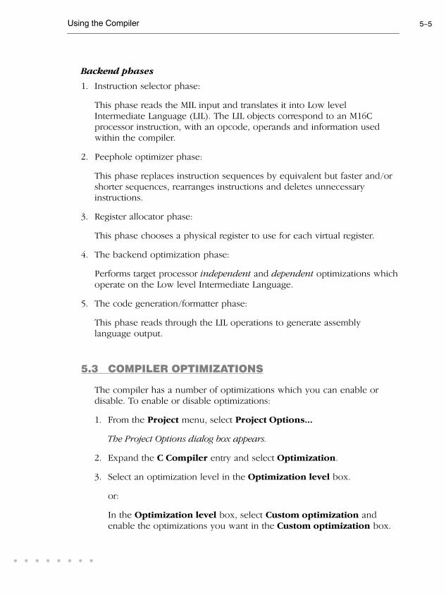
Using the Compiler 5-5
• • • • • • • •
Backend phases
1. Instruction selector phase:
This phase reads the MIL input and translates it into Low level
Intermediate Language (LIL). The LIL objects correspond to an M16C
processor instruction, with an opcode, operands and information used
within the compiler.
2. Peephole optimizer phase:
This phase replaces instruction sequences by equivalent but faster and/or
shorter sequences, rearranges instructions and deletes unnecessary
instructions.
3. Register allocator phase:
This phase chooses a physical register to use for each virtual register.
4. The backend optimization phase:
Performs target processor independent and dependent optimizations which
operate on the Low level Intermediate Language.
5. The code generation/formatter phase:
This phase reads through the LIL operations to generate assembly
language output.
5.3 COMPILER OPTIMIZATIONS
The compiler has a number of optimizations which you can enable or
disable. To enable or disable optimizations:
1. From the Project menu, select Project Options...
The Project Options dialog box appears.
2. Expand the C Compiler entry and select Optimization.
3. Select an optimization level in the Optimization level box.
or:
In the Optimization level box, select Custom optimization and
enable the optimizations you want in the Custom optimization box.

User's Manual5-6COMPILER
Optimization levels
The TASKING C compilers offer four optimization levels and a custom
level, at each level a specific set of optimizations is enabled.
• Level 0: No optimizations are performed. The compiler tries to achieve
a 1-to-1 resemblance between source code and produced code.
Expressions are evaluated in the order written in the source code,
associative and commutative properties are not used.
• Level 1: Enables optimizations that do not affect the debug-ability of
the source code. Use this level when you are developing/debugging
new source code.
• Level 2: Enables more aggressive optimizations to reduce the memory
footprint and/or execution time. The debugger can handle this code
but the relation between source code and generated instructions may
be hard to understand. Use this level for those modules that are already
debugged. This is the default optimization level.
• Level 3: Enables aggressive global optimization techniques. The
relation between source code and generated instructions can be very
hard to understand. The debugger does not crash, will not provide
misleading information, but does not fully understand what is going
on. Use this level when your program does not fit in the memory
provided by your system anymore, or when your program/hardware
has become too slow to meet your real-time requirements.
• Custom level: you can enable/disable specific optimizations.
Optimization pragmas
If you specify a certain optimization, all code in the module is subject to
that optimization. Within the C source file you can overrule the compiler
options for optimizations with #pragma optimize flag and #pragma
endoptimize. Nesting is allowed:
#pragma optimize e /* Enable expression
... simplification */
... C source ...
...
#pragma optimize c /* Enable common expression
... elimination. Expression
... C source ... simplification still enabled */
...
#pragma endoptimize /* Disable common expression
... elimination */
#pragma endoptimize /* Disable expression
... simplification */
The compiler optimizes the code between the pragma pair as specified.
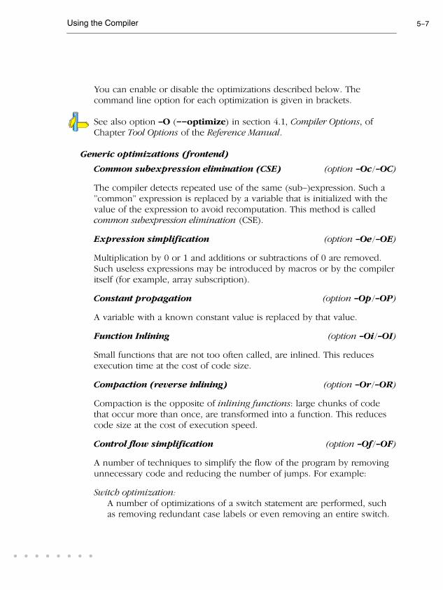
Using the Compiler 5-7
• • • • • • • •
You can enable or disable the optimizations described below. The
command line option for each optimization is given in brackets.
See also option -O (--optimize) in section 4.1, Compiler Options, of
Chapter Tool Options of the Reference Manual.
Generic optimizations (frontend)
Common subexpression elimination (CSE) (option -Oc/-OC)
The compiler detects repeated use of the same (sub-)expression. Such a
"common" expression is replaced by a variable that is initialized with the
value of the expression to avoid recomputation. This method is called
common subexpression elimination (CSE).
Expression simplification (option -Oe/-OE)
Multiplication by 0 or 1 and additions or subtractions of 0 are removed.
Such useless expressions may be introduced by macros or by the compiler
itself (for example, array subscription).
Constant propagation (option -Op/-OP)
A variable with a known constant value is replaced by that value.
Function Inlining (option -Oi/-OI)
Small functions that are not too often called, are inlined. This reduces
execution time at the cost of code size.
Compaction (reverse inlining) (option -Or/-OR)
Compaction is the opposite of inlining functions: large chunks of code
that occur more than once, are transformed into a function. This reduces
code size at the cost of execution speed.
Control flow simplification (option -Of/-OF)
A number of techniques to simplify the flow of the program by removing
unnecessary code and reducing the number of jumps. For example:
Switch optimization:A number of optimizations of a switch statement are performed, such
as removing redundant case labels or even removing an entire switch.

User's Manual5-8COMPILER
Jump chaining:A (conditional) jump to a label which is immediately followed by an
unconditional jump may be replaced by a jump to the destination label
of the second jump. This optimization speeds up execution.
Conditional jump reversal:A conditional jump over an unconditional jump is transformed into one
conditional jump with the jump condition reversed. This reduces both
the code size and the execution time.
Dead code elimination:Code that is never reached, is removed. The compiler generates a
warning messages because this may indicate a coding error.
Subscript strength reduction (option -Os/-OS)
An array of pointer subscripted with a loop iterator variable (or a simple
linear function of the iterator variable), is replaced by the dereference of a
pointer that is updated whenever the iterator is updated.
Loop transformations (option -Ol/-OL)
Temporarily transform a loop with the entry point at the bottom, to a loop
with the entry point at the top. This enables constant propagation in the
initial loop test and code motion of loop invariant code by the CSEoptimization.
Forward store (option -Oo/-OO)
A temporary variable is used to cache multiple assignments (stores) to the
same non-automatic variable.
Core specific optimizations (backend)
Coalescer (option -Oa/-OA)
The coalescer seeks for possibilities to reduce the number of moves (MOV
instruction) by smart use of registers. This optimizes both speed as code
size.
Interprocedural register optimization (option -Ob/-OB)
Register allocation is improved by taking note of register usage in
functions called by a given function.

Using the Compiler 5-9
• • • • • • • •
Peephole optimizations (option -Oy/-OY)
The generated assembly code is improved by replacing instruction
sequences by equivalent but faster and/or shorter sequences, or by
deleting unnecessary instructions.
Generic assembly optimizations (option -Og/-OG)
A set of target independent optimizations that increase speed and decrease
code size.
Optimize 'call+return' to jump (option -Oz/-OZ)
A function call which is immediately followed by a function return is
replaced by a jump. With this optimization a call trace is no longer
possible.
5.3.1 OPTIMIZE FOR SIZE OR SPEED
You can tell the compiler to focus on execution speed or code size during
optimizations. You can do this by specifying a size/speed trade-off level
from 0 (speed) to 4 (size). This trade-off does not turn optimization
phases on or off. Instead, its level is a weight factor that is used in the
different optimization phases to influence the heuristics. The higher the
level, the more the compiler focuses on code size optimization.
To specify the size/speed trade-off optimization level:
1. From the Project menu, select Project Options...
The Project Options dialog box appears.
2. Expand the C Compiler entry and select Optimization.
3. Select one of the options Optimize for size or Optimize for speed.
See also option -t (--tradeoff) in section 4.1, Compiler Options, inChapter Tool Options of the Reference Manual.

User's Manual5-10COMPILER
5.4 CALLING THE COMPILER
EDE uses a makefile to build your entire project. This means that you
cannot run the compiler only. If you compile a single C source file from
within EDE, the file is also automatically assembled. However, you can set
options specific for the compiler. After you have build your project, the
output files of the compilation step are available in your project directory.
To compile your program, click either one of the following buttons:
Compiles and assembles the currently selected file. This
results in a relocatable object file (.obj).
Builds your entire project but looks whether there are already
files available that are needed in the building process. If so,
these files will not be generated again, which saves time.
Builds your entire project unconditionally. All steps necessary
to obtain the final .elf file are performed.
To only check for syntax errors, click the following button:
Checks the currently selected file for syntax errors, but does
not generate code.
Select a target processor (core)
Because the toolchain supports several processor cores, you need to
choose a processor type first.
To access the M16C processor options:
1. From the Project menu, select Project Options...
The Project Options dialog box appears.
2. Expand the Processor entry and select Processor Definition.
3. In the Select processor list select the target processor.
4. (Optional) Fill in the Startup Code page.
5. Click OK to accept the processor options.
Processor options affect the invocation of all tools in the toolchain. InEDE you only need to set them once. The corresponding options for thecompiler are listed in table 5-1.

Using the Compiler 5-11
• • • • • • • •
Based on the target processor, the compiler includes a special functionregister file regcpu.sfr. This is an include file written in C syntax which
is shared by the compiler, assembler and debugger. Once the compiler
reads an SFR file you can reference the special function registers (SFR) and
bits within an SFR using symbols defined in the SFR file.
To specify the search path and include directories
1. From the Project menu, select Directories...
The Directories dialog box appears.
2. Fill in the directory path settings and click OK.
To access the compiler options
1. From the Project menu, select Project Options...
The Project Options dialog box appears.
2. Expand the C Compiler entry, fill in the various pages and click OK to
accept the compiler options.
The compiler command line equivalences of your EDE selections areshown simultaneously in the Options string box.
The following processor options are available:
EDE options Command line
Processor Definition
Select processor -Ccpu
Compile for R8C/tiny instead of M16C/60 --r8c
Memory
Internal memory EDE only
Startup Code
Add <project>_cstart.src to your project EDE only
Table 5-1: Processor options

User's Manual5-12COMPILER
The following project directories are available:
EDE options Command line
Directories
Executable files path
Include files path
Library files path
$PATH environment
-Idir
linker option -Ldir
Table 5-2: Project directories
The following compiler options are available:
EDE options Command line
Memory Models
Compile using small/medium/large memory model -M{s|m|l}
Code Generation
Keep strings in ROM --romstrings
Keep constants in ROM --romconstants
ROM is available in first 64k of memory --near-rom
Generate code for fixed interrupt vector --novector
Generate frame for interrupt routines --noframe
Preprocessing
Define user macro -Dmacro[=def]
Include an extra file at the beginning of the C source -Hfile
Store the C compiler preprocess output (file.pre) -Eflag
Alignment
Align functions to an even address --align-func
Align data to an even address --align-data
Optimization
Optimization level
Custom optimization
-O{0|1|2|3}
-Oflag
Optimize for size/speed -t{0|4}
Language
ISO C standard 90 or 99 (default: 99) -c{90|99}
Treat 'char' variables as unsigned instead of signed -u
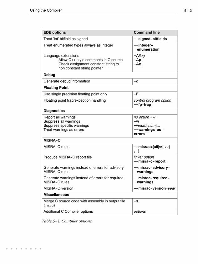
Using the Compiler 5-13
• • • • • • • •
Command lineEDE options
Treat 'int' bitfield as signed --signed-bitfields
Treat enumerated types always as integer --integer- enumeration
Language extensions
Allow C++ style comments in C source
Check assignment constant string to
non constant string pointer
-Aflag-Ap-Ax
Debug
Generate debug information -g
Floating Point
Use single precision floating point only -F
Floating point trap/exception handling control program option--fp-trap
Diagnostics
Report all warnings
Suppress all warnings
Suppress specific warnings
Treat warnings as errors
no option -w-w-wnum[,num]...
--warnings-as-errors
MISRA-C
MISRA-C rules --misrac={all|nr[-nr],...}
Produce MISRA-C report file linker option--misra-c-report
Generate warnings instead of errors for advisory
MISRA-C rules
--misrac-advisory- warnings
Generate warnings instead of errors for required
MISRA-C rules
--misrac-required- warnings
MISRA-C version --misrac-version=year
Miscellaneous
Merge C source code with assembly in output file
(.src)
-s
Additional C Compiler options options
Table 5-3: Compiler options

User's Manual5-14COMPILER
The following options are available on the command line, and you can set
them in EDE through the Additional C Compiler options field in the
Miscellaneous page:
Description Command line
Display invocation syntax -?
Align all objects on an even address --align
Maximum size of a match with code compaction
(default: 200)
--compact-max-size= value
Redirect diagnostic messages to a file --error-file[=file]
Read options from file -f file
Always inline function calls --inline
Maximum size increment inlining (in %) (default: 25) --inline-max-incr=value
Maximum size for function to always inline
(default: 10)
--inline-max-size=value
Keep output file after errors -k
Maximum call depth, default infinite
(default: -1)
--max-call-depth=value
Send output to standard output -n
Do not clear non-initialized global variables --noclear
Do not generate frame for interrupt handler --noframe
Specify name of output file -o file
Rename sections -Rmem=name
Treat external definitions as "static" --static
Display version header only -V
Table 5-4: Compiler options only available on the command line
The invocation syntax on the command line is:
cm16c [option]... [file]
The input file must be a C source file (.c or .ic).
cm16c test.c

Using the Compiler 5-15
• • • • • • • •
This compiles the file test.c and generates the file test.src which
serves as input for the assembler.
For a complete overview of all options with extensive description, see
section 4.1, Compiler Options, of Chapter Tool Options of the ReferenceManual.
5.5 HOW THE COMPILER SEARCHES INCLUDE FILES
When you use include files, you can specify their location in several ways.
The compiler searches the specified locations in the following order:
1. The absolute pathname, if specified in the #include statement. Or, if no
path or a relative path is specified, the same directory as the source file.
This is only possible for include files that are enclosed in "".
This first step is not done for include files enclosed in <>.
2. The directories that are specified in the Project | Directories dialog (-I
option).
3. The paths which were set during installation. You can still change these
paths.
See section 1.3.1, Configuring the Embedded Development Environmentand environment variable CM16CINC in section 1.3.2, Configuring theCommand Line Environment, in Chapter Software Installation.
4. The default include directory relative to the installation directory.
5.6 COMPILING FOR DEBUGGING
Compiling your files is the first step to get your application ready to run
on a target. However, during development of your application you first
may want to debug your application.
To create an object file that can be used for debugging, you must instruct
the compiler to include symbolic debug information in the source file.
To include symbolic debug information
1. From the Project menu, select Project Options...

User's Manual5-16COMPILER
The Project Options dialog box appears.
2. Expand the C Compiler entry and select Debug Information.
3. Enable the option Generate debug information.
4. Click OK to accept the new project settings.
cm16c -g
Debug and optimizations
Due to different compiler optimizations, it might be possible that certain
debug information is optimized away. Therefore, it is best to specify
Debug purpose (-O1) when you want to debug your application. This is
a special optimization level where the source code is still suitable for
debugging.
1. From the Project menu, select Project Options...
The Project Options dialog box appears.
2. Expand the C Compiler entry and select Optimization.
3. In the Optimization level box, select Debug purpose.
5.7 C CODE CHECKING: MISRA-C
The C programming language is a standard for high level language
programming in embedded systems, yet it is considered somewhat
unsuitable for programming safety-related applications. Through enhanced
code checking and strict enforcement of best practice programming rules,
TASKING MISRA-C code checking helps you to produce more robust
code.
MISRA-C specifies a subset of the C programming language which is
intended to be suitable for embedded automotive systems. It consists of a
set of rules, defined by MISRA-C:2004 in Guidelines for the use of the CLanguage in critical systems (MIRA Limited, 2004).

Using the Compiler 5-17
• • • • • • • •
The compiler also supports the MISRA-C:1998 version of the MISRA-C
rules. You can select this version with the following C compiler option:
--misrac-version=1998
For a complete overview of all MISRA-C rules, see Chapter 8, MISRA-CRules, in the Reference Manual.
Implementation issues
The MISRA-C implementation in the compiler supports nearly all rules.
Only few rules are not supported because they address documentation,
run-time behavior, or other issues that cannot be checked by static source
code inspection, or because they require an application-wide overview.
During compilation of the code, violations of the enabled MISRA-C rules
are indicated with error messages and the build process is halted.
MISRA-C rules are divided in required rules and advisory rules. If rules are
violated, errors are generated causing the compiler to stop. With the
following options warnings, instead of errors, are generated for either or
both the required rules and the advisory rules:
--misrac-required-warnings
--misrac-advisory-warnings
Note that not all MISRA-C violations will be reported when other errors
are detected in the input source. For instance, when there is a syntax error,
all semantic checks will be skipped, including some of the MISRA-C
checks. Also note that some checks cannot be performed when the
optimizations are switched off.
Quality Assurance report
To ensure compliance to the MISRA-C rules throughout the entire project,
the TASKING M16C linker can generate a MISRA-C Quality Assurance
report. This report lists the various modules in the project with the
respective MISRA-C settings at the time of compilation. You can use this in
your company's quality assurance system to provide proof that company
rules for best practice programming have been applied in the particular
project.

User's Manual5-18COMPILER
Apply MISRA-C code checking to your application
1. From the Project menu, select Project Options...
The Project Options dialog box appears.
2. Expand the C Compiler entry and select MISRA-C.
3. Select a MISRA-C configuration. Select a predefined configuration for
conformance with the required rules in the MISRA-C guidelines.
It is also possible to read a MISRA-C configuration from an external
file.
4. (Optional) In the MISRA-C Rules entry, specify the individual rules.
cm16c --misrac={all | number [-number],...}
See compiler option --misrac in section 4.1, Compiler Options in Chapter
Tool Options of the Reference Manual.
See linker option --misra-c-report in section 4.3, Linker Options inChapter Tool Options of the Reference Manual.

Using the Compiler 5-19
• • • • • • • •
5.8 C COMPILER DIAGNOSTICS
At compile time, the cm16c compiler reports the following types of error
messages:
F Fatal errors
After a fatal error the compiler immediately aborts compilation.
E Errors
Errors are reported, but the compiler continues compilation. No output
files are produced unless you have set the compiler option
--keep-output-files (the resulting output file may be incomplete).
W Warnings
Warning messages do not result into an erroneous assembly output file.
They are meant to draw your attention to assumptions of the compiler for
a situation which may not be correct. You can control warnings in the C
Compiler | Diagnostics page of the Project | Project Options... menu
(compiler option -w).
I Information
Information messages are always preceded by an error message.
Information messages give extra information about the error.
S System errors
System errors occur when internal consistency checks fail and should
never occur. When you still receive the system error message
S9##: internal consistency check failed - please report
please report the error number and as many details as possible about the
context in which the error occurred. The following helps you to prepare
an e-mail using EDE:
User's Manual5-20COMPILER
1. From the Help menu, select Technical Support -> Prepare Email...
The Prepare Email form appears.
2. Fill out the the form. State the error number and attach relevant files.
3. Click the Copy to Email client button to open your email application.
A prepared e-mail opens in your e-mail application.
4. Finish the e-mail and send it.
Display detailed information on diagnostics
1. In the Help menu, enable the option Show Help on Tool Errors.
2. In the Build tab of the Output window, double-click on an error or
warning message.
A description of the selected message appears.
cm16c --diag=[format:]{all | number,...}
See compiler option --diag in section 4.1, Compiler Options in Chapter
Tool Options of the Reference Manual.

Using the Compiler 5-21
• • • • • • • •
5.9 RUN-TIME ERROR CHECKING
To be able to perform run-time error checking, the compiler adds extra
code to your C source. Because of the inserted code, applications will run
slower and require more memory. Therefore it is recommended to use
run-time checking only during the development of the software.
A message is printed on stdout (which is connected to the CrossView
Terminal Window) if an run-time error is detected. Every message is
preceded by the code address where the error was detected. The source
file name and line number are not printed, because that would increase
the code and data size. To obtain the source position, you can either
lookup the address in the map file, or set a breakpoint on
__runtime_error in the debugger to back-trace the error.
Run-time error checking can be done at application wide scope or at
module scope. Only malloc() checks are always executed at application
wide scope.
The following run-time checks are available:
Bounds checking
Bounds checking verifies all pointer operations to detect buffer overflows
and other illegal operations. The bounds checking code keeps track of the
bounds of all objects that may have their address taken somewhere in the
application.
Pointer arithmetic
When a pointer is incremented or decremented, the old and new values
should point to the same object: it would be an error if the new pointer
value is outside the current object. Likewise, comparing or subtracting
pointers to different objects results in undefined behavior according to the
ISO C standard, and will be flagged as well.
Dereferencing invalid pointer
The ISO C standard allows a pointer to point to the first byte after an
object, but dereferencing such a pointer is an error. Therefore, a pointer to
the first address after an object is considered to point "inside" the object,
but dereferencing the pointer will be flagged by the bounds checking
code.
User's Manual5-22COMPILER
Uninitialized pointers / null pointer
Uninitialized automatic pointers are initialized to a special value that
triggers a run-time error when used. Dereferencing or updating a null
pointer will also trigger a run-time error.
Considerations
• Sub-objects such as structure members, or objects from a memory pool
in the application are not checked for overflow.
• An offset calculation in a static pointer initializer is performed by the
assembler, and cannot be checked.
• Pointers to function parameters cannot be checked.
Unhandled case in a switch
This option reports an unhandled case value in a switch without a default
part. It simply completes any switch without a default part with an extra
function call. This has little impact on the execution speed. To avoid this
type of run-time error, add an empty default part to the case switch
when the switch is not supposed to have a case for every possible value.
Malloc checks
This option uses wrappers around the functions malloc(), realloc()
and free() that will check for common dynamic memory allocation
errors like:
• buffer overflow
• write to freed memory
• multiple calls to free
• passing an invalid pointer to free
For this check some additional code from the library is extracted, but it has
minimal impact on on your application code size. The dynamic memory
usage increases only by a couple of bytes per allocation.
Memory allocated by malloc() is deliberately initialized with a non-zero
value to force a failure when the application fails to initialize the memory.
To detect a buffer overflow, a sentinel byte is placed directly after every
allocation. The sentinel is checked when the memory is freed. Likewise, a
"magic" number before the allocation makes it possible to detect a buffer
underflow. This duplicates some functionality of the bounds checking, but
with lower overhead.
Using the Compiler 5-23
• • • • • • • •
A call to free() overwrites the memory to force a failure when the
memory is used after it has been freed. To detect modification of memory
that has been freed, a call to malloc() will check the items freed since the
previous call (with a maximum of 4) for changes.
Stack overflow
This option adds a test for stack overflow at the start of every function and
for every variable length array declaration. Enabling this check will extend
the function prolog code with a stack overflow test.
Because the functions that report the stack overflow need some stack
space themselves, the overflow is reported before the limit is reached. This
margin is set at 24 bytes.
Division by zero
Reports division by zero when during program execution an attempt was
made to divide by zero. This check will test the divisor just before a
division takes place.
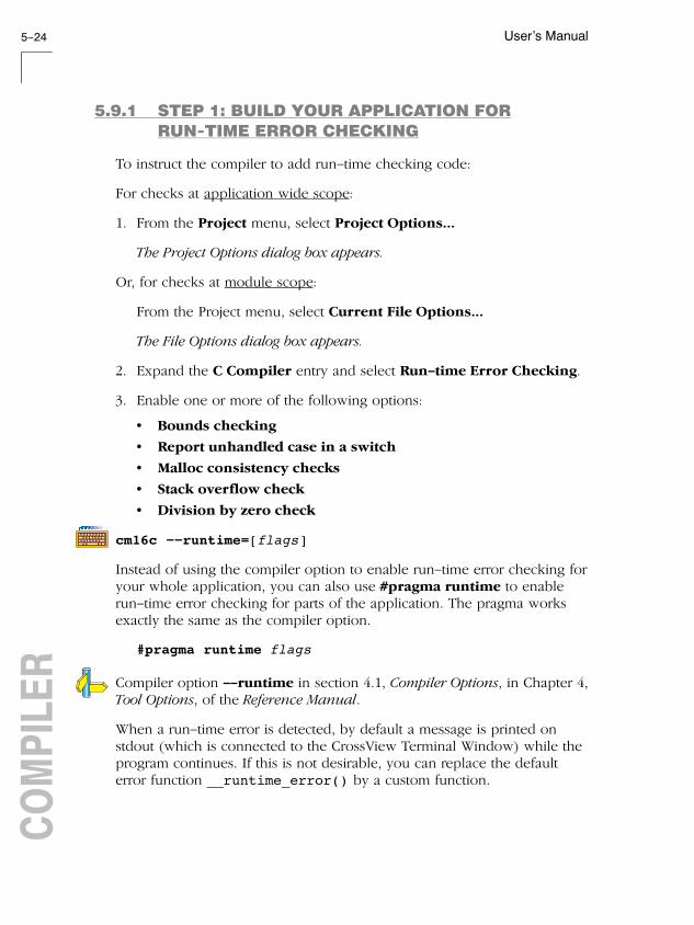
User's Manual5-24COMPILER
5.9.1 STEP 1: BUILD YOUR APPLICATION FOR
RUN-TIME ERROR CHECKING
To instruct the compiler to add run-time checking code:
For checks at application wide scope:
1. From the Project menu, select Project Options...
The Project Options dialog box appears.
Or, for checks at module scope:
From the Project menu, select Current File Options...
The File Options dialog box appears.
2. Expand the C Compiler entry and select Run-time Error Checking.
3. Enable one or more of the following options:
• Bounds checking
• Report unhandled case in a switch
• Malloc consistency checks
• Stack overflow check
• Division by zero check
cm16c --runtime=[flags]
Instead of using the compiler option to enable run-time error checking for
your whole application, you can also use #pragma runtime to enable
run-time error checking for parts of the application. The pragma works
exactly the same as the compiler option.
#pragma runtime flags
Compiler option --runtime in section 4.1, Compiler Options, in Chapter 4,
Tool Options, of the Reference Manual.
When a run-time error is detected, by default a message is printed on
stdout (which is connected to the CrossView Terminal Window) while the
program continues. If this is not desirable, you can replace the default
error function __runtime_error() by a custom function.

Using the Compiler 5-25
• • • • • • • •
5.9.2 STEP 2: EXECUTE THE APPLICATION
Once you have compiled and linked the application for run-time error
checking, it must be executed. Start CrossView Pro and run your
application in simulation mode.
Run the program as usual: the program should run normally taking the
same input as usual and producing the same output as usual. The
application will run somewhat slower that normal because of the extra
time spent on performing the error checks.
Small heap problem
When the program does not run as usual, this is typically caused by a
shortage of heap space. In this case an out of memory message is issued
(when running with file system simulation, it is displayed in the FSS0
Terminal window).
To solve this problem, increase the size of the heap:
1. From the Project menu, select Project Options...
The Project Options dialog box appears.
2. Expand the Linker entry and select Stack/Heap
3. Enter a new value for Heap size (in bytes), for example 1000.
Below are a number of code examples which generate the possible errors
for the several run-time error checking options.
5.9.3 EXAMPLES PRODUCING RUN-TIME ERRORS
Example 1: Bounds checking
C source
int sum (int* arr, int n)
{
int total = 0;
for (int i = 0; i < n; i++)
{
total += arr[i];
}
return total;
}

User's Manual5-26COMPILER
int distance (int* arr1, int* arr2)
{
if (arr2 > arr1)
{
return arr2 - arr1;
}
else
{
return arr1 - arr2;
}
}
char* inc (char* ptr)
{
return ptr + 10;
}
int deref (char* ptr)
{
return *ptr;
}
int list1 [] = {1, 2, 3, 4, 5};
int list2 [] = {6, 7, 8, 9, 10};
int main (void)
{
char* uninit1;
static char* uninit2;
sum(list1, 5); // OK
sum(list1, 6); // overflow
distance(list1+1, list1+5); // OK
distance(list1+1, list2+5); // different objects
inc(uninit1); // uninitialized pointer
inc(uninit2); // null pointer
deref(uninit1); // uninitialized pointer
deref(uninit2); // null pointer
return 0;
}
Ouput
error at 000c2283: access beyond end of object
[00000600,0000060a]
error at 000c2294: pointer a008001a outside object
[00000600,0000060a]
error at 000c22d3: comparing pointers to different objects
(00000616/00000602)
error at 000c22f1: subtracting pointers to different objects
(00000616/00000602)
error at 000c23d9: arithmetic on uninitialized pointer
error at 000c23e0: arithmetic on null pointer
error at 000c2356: dereferencing uninitialized pointer
error at 000c2356: dereferencing null pointer

Using the Compiler 5-27
• • • • • • • •
Example 2: Unhandled case
C source
int sum (int* arr, int n)
{
int total = 0;
for (int i = 0; i < n; i++)
{
total += arr[i];
}
return total;
}
Ouput
error at 000c16b6: unhandled case
Example 3: Malloc checks
C source
#include <stdlib.h>
#include <string.h>
typedef struct
{
char* item1;
char* item2;
} node_t;
int main (void)
{
char* buf = malloc(5);
strcpy(buf, "hello"); // error: buffer too small
free(buf); // OK
free(buf); // error: duplicate free
free(&buf); // error: invalid pointer
*buf = '\0'; // error: writing to freed memory
node_t* node = malloc(sizeof(node_t));
free(node->item1); // error: uninitialized memory
free(node); // OK
free(node->item2); // error: deallocated memory
}

User's Manual5-28COMPILER
Ouput
error at 000c240b: malloc buffer overflow
(address 00000e0e, size 5)
error at 000c2415: memory already freed
(address 00000e0e, size 5)
error at 000c241e: calling free with an invalid pointer
(00000859)
error at 000c243b: freed memory was modified
(address 00000e0e, size 5)
error at 000c245b: calling free with an invalid pointer
(aaaaaaaa)
error at 000c2491: calling free with an invalid pointer
(bbbbbbbb)
Example 4: Stack overflow
C source
void main (void)
{
int bigsize = 10000;
int array[bigsize]; // stack overflow. Calls abort.
}
Ouput
error at 000c2ab2: stack overflow
Example 5: Division by zero
C source
#include <stdio.h>
int b=0;
float f;
int main (void)
{
f=10/b;
printf("f=%f",f);
return f;
}
Ouput
error at 000c3ab5: division by zero

6
PROFILINGC
HA
PT
ER

User's Manual6-2C
LA
NG
UA
GE
6
CH
AP
TE
R

C Language 6-3
• • • • • • • •
6.1 WHAT IS PROFILING?
Profiling is a collection of methods to gather data about your application
which helps you to identify code fragments where execution consumes
the greatest amount of time.
TASKING supplies a number of profiler tools each dedicated to solve a
particular type of performance tuning problem. Performance problems can
be solved by:
• Identifying time-consuming algorithms and rewrite the code using a
more time-efficient algorithm.
• Identifying time-consuming functions and select the appropriate
compiler optimizations for these functions (for example, enable
loop unrolling or function inlining).
• Identifying time consuming loops and add the appropriate pragmas
to enable the compiler to further optimize these loops.
A profiler helps you to find and identify the time consuming constructs
and provides you this way with valuable information to optimize your
application.
TASKING employs various schemes for collecting profiling data,
depending on the capabilities of the target system and different
information needs.

User's Manual6-4C
LA
NG
UA
GE
6.1.1 THREE METHODS OF PROFILING
There are several methods of profiling: recording by an instruction set
simulator, profiling using the debugger and profiling with code
instrumentation techniques. Each method has its advantages and
disadvantages.
Profiling by an instruction set simulator
On way way to gather profiling information is built into the instruction set
simulator (ISS). The ISS records the time consumed by each instruction
that is executed. The debugger then retrieves this information and
correlates the time spent for individual instructions to C source statements.
Advantages
- it gives (cycle) accurate information with extreme fine granularity
- the executed code is identical to the non-profiled code
Disadvantages
- the method requires an ISS as execution environment
Profiling with the debugger
The second method of profiling is built into the debugger. You specify
which functions you want to profile. The debugger places breakpoints on
the function entry and all its exit addresses and measures the time spent in
the function and its callees.
Advantages
- the executed code is identical to the non-profiled code
Disadvantage
- each time a profiling breakpoint is hit the target is stopped and control
is passed to the debugger. Although the debugger restarts the
application immediately, the application's performance is significantly
reduced.
See Section Profiling in Chapter Special Features of the CrossView Pro
Debugger User's Manual.

C Language 6-5
• • • • • • • •
Profiling using code instrumentation techniques
The TASKING compiler contains an option to add code to your application
which takes care of the profiling process. This is called codeinstrumentation. The gathered profiling data is first stored in the target's
memory and will be written to a file when the application finishes
execution or when the function __prof_cleanup() is called.
Advantages
- it can give a complete call graph of the application annotated with the
time spend in each function and basic block
- this profiling method is execution environment independent
- the application is profiled while it executes on its aimed target taking
real-life input
Disadvantage
- instrumentation code creates a significant run-time overhead, and
instrumentation code and gathered data take up target memory
This method provides a valuable complement to the other two methods
and will be described into more detail below.
6.2 PROFILING USING CODE INSTRUMENTATION
Profiling can be used to determine which parts of a program take most of
the execution time.
Once the collected data are presented, it may reveal which parts of your
code execute slower than expected and which functions contribute most
to the overall execution time of a program. It gives you also information
about which functions are called more or less often than expected. This
information not only may reveal design flaws or bugs that had otherwise
been unnoticed, it also reveals parts of the program which can be
effectively optimized.

User's Manual6-6C
LA
NG
UA
GE
Important considerations
The code instrumentation method adds code to your original application
which is needed to gather the profiling data. Therefore, the code size of
your application increases. Furthermore, during the profiling process, the
gathered data is initially stored into dynamically allocated memory of the
target. The heap of your application should be large enough to store this
data. Since code instrumentation is done by the compiler, assembly
functions used in your program do not show up in the profile.
The profiling information is collected during the actual execution of the
program. Therefore, the input of the program influences the results. If a
part/function of the program is not activated while the program is profiled,
no profile data is generated for that part/function.
It is possible to execute the application multiple times (while varying the
input data) and combine the profiling results of those runs.
(See section 6.2.3, Step 3: displaying profiling results).
Overview of steps to perform
To obtain a profile using code instrumentation, perform the following
steps:
1. Compile and link your program with profiling enabled
2. Execute the program to generate the profiling data
3. Display the profiling results

C Language 6-7
• • • • • • • •
6.2.1 STEP 1: BUILD YOUR APPLICATION FOR
PROFILING
The first step is to add the code that takes care of the profiling, to your
application. This is done with compiler options:
For profiling at application wide scope:
1. From the Project menu, select Project Options...
The Project Options dialog box appears.
Or, for profiling at module scope:
From the Project menu, select Current File Options...
The File Options dialog box appears.
2. Expand the C Compiler entry and select Profiler.
3. Enable one or more of the following profiler options to select which
profiles should be obtained.
• Block counters (not with Call graph or Function timers)
• Call graph
• Function counters
• Function timers
Block counters (not in combination with Call graph or Time)
This will instrument the code to perform basic block counting. As
the program runs, it will count how many time it executed each
branch of each if statement, each iteration of a for loop, and so
on. Note that though you can combine Block counters with
Function counters, this has no effect because Function counters is a
subset of Block counters.
Call graph (not in combination with Block counters)
This will instrument the code to reconstruct the run-time call graph.
As the program runs it stores the relation between the caller and the
gathered profiling data.
Function counters
This will instrument the code to perform function call counting. This
is a subset of the basic Block counters.

User's Manual6-8C
LA
NG
UA
GE
Time (not in combination with Block counters)
This will instrument the code to measure the time spent in a
function. This includes the time spent in all called functions
(callees).
Clock(): ticks per second
The profiler uses the C library function clock() to measure time.
This is a target dependent function. Default, the clock() function
is implemented for the Tasking simulator which runs at 10 MHz. If
you do not use the simulator for execution, you must provide your
own clock() function. To obtain correct time measurements, fill in
the resolution of your clock() function (in MHz). The default is 10
MHz.
4. From the Build menu select Rebuild.
For the command line, see the command line compiler option -p
(--profile) in Section 4.1, Compiler Options in Chapter Tool Options of
the reference manual.
6.2.1.1 PROFILING MODULES AND LIBRARIES
Profiling individual modules
It is possible to profile individual C modules. In this case only limited
profiling data is gathered for the functions in the modules compiled
without the profiling option. When you use the suboption Call graph, the
profiling data reveals which profiled functions are called by non-profiled
functions. The profiling data does not show how often and from where
the non-profiled functions themselves are called. Though this does not
affect the flat profile, it might reduce the usefulness of the call graph.
Profiling library functions
EDE and/or the control program tcc will link your program with the
standard version of the C library libc*.a. Functions from this library
which are used in your application, will not be profiled. If you do want to
incorporate the library functions in the profile, you must set the
appropriate compiler options in the C library makefiles and rebuild the
library.

C Language 6-9
• • • • • • • •
6.2.1.2 LINKING PROFILING LIBRARIES
When building your application, the application must be linked against a
profile library. EDE (or the control program tcc) automatically select the
correct library based on the profiling options you specified. However, if
you compile, assemble and link your application manually, make sure you
specify the correct library.
See Section 8.4, Linking with Libraries in Chapter Using the Linker for an
overview of the (profiling) libraries.
6.2.2 STEP 2: EXECUTE THE APPLICATION
Once you have compiled and linked the application for profiling, it must
be executed to generate the profiling data. Run the program as usual: the
program should run normally taking the same input as usual and
producing the same output as usual. The application may run somewhat
slower than normal because of the extra time spent on collecting the
profiling data.
Startup code
The startup code initializes the profiling functions by calling the function
__prof_init(). EDE will automatically make the required modifications
to the startup code. Or, when you use the control program, this extracts
the correct startup code from the C library.
If you use your own startup code, you must manually insert a call to the
function __prof_init just before the call to _main and its stack setup.
An application can have multiple entry points, such as main() and other
functions that are called by interrupt. This does not affect the profiling
process.

User's Manual6-10C
LA
NG
UA
GE
Small heap problem
When the program does not run as usual, this is typically caused by a
shortage of heap space. In this case an out of memory message is issued.
(When running with file system simulation, it is displayed on the Debug
console.)
To solve this problem, increase the size of the heap:
1. From the Project menu, select Project Options...
The Project Options dialog box appears.
2. Expand the Linker entry and select Stack/Heap
3. Enter a new value for Heap size (in bytes).
After execution
When the program has finished (returning from main()), the exit code
calls the function __prof_cleanup(). This function writes the gathered
profiling data to a file on the host system using the debugger's file system
simulation features. If your program does not return from main(), you
can force this by inserting a call to the function __prof_cleanup() in
your application source code. Please note the double underscores when
calling from C code!
The resulting profiling data file is named amon.prf. This file is written to
the current working directory.
If your program does not run under control of the debugger and therefore
cannot use the file simulation system (FSS) functionality to write a file to
the host system, you must implement a way to pass the profiling data
gathered on the target to the host. Adapt the function _prof_cleanup()
in the profiling libraries or the underlying I/O functions for this purpose.

C Language 6-11
• • • • • • • •
6.2.3 STEP 3: DISPLAYING PROFILING RESULTS
The result of the profiler can be displayed in EDE.
1. Return to the EDE window.
2. In EDE, from the Build menu select Profile.
The Select Profile Files dialog appears.
Normally, profiling information is stored in the file amon.prf.
However, you can rename this file to keep previous results.
3. Browse to the profile file you want to display
(amon.prf or one of the renamed profiling files).
It is possible to select multiple .prf files. The results are combined.
4. Click OK to confirm.
The profile information of the selected file is displayed in the Profilingtab of the Output window.
The Output-Profiling window
Results table Shows the timing and call information for all functions
and/or blocks in the profile.
Callers table Shows the functions that called the focus function.
Callees table Shows the functions that are called by the focus function.
• Double clicking on a function in a table, makes the function the
focus function.
• To sort the rows in the table, click on one of the column headers.
• Right-clicking in a table opens a quick-access menu.
• With the copy functions it is possible to copy a table (or selected
rows) to other applications. To select one or more rows, hold down
the Shift-key or Ctrl-key and click the rows you want to add to the
selection.

User's Manual6-12C
LA
NG
UA
GE
The profiling information
Based on the profiling options you have set before compiling your
application, some columns in the profiling window may remain empty.
The columns in the tables represent the following information:
In the results table:
Module The C source module in which the function resides.
#Line Line number of first statement in the Function.
Function The function for which profiling data is gathered and
(if present) the code block number.
Total time Total amount of time (seconds) that was spend in the
function. This includes the time spent in callees of the
function.
Self time Total amount of time (seconds) that was spend executing
the command of the function itself. This excludes the
spent in callees of the function.
% in function The relative amount of time spent in this function. These
should add up to 100%.
Calls/Block Counts
Number of calls (function counters) and basic block
counts.
#Callers Number of functions by which this function is called.
Each function should have at least one caller (except
_START).
#Callees Number of different functions that can be called from this
function.

C Language 6-13
• • • • • • • •
In the caller table:
Module The C source module in which the function resides.
#Line Line number of first statement in the Function.
Caller The name(s) of the function(s) which called the focus
function.
Total time Total amount of time (seconds) that was spend in the
focus function. This includes the time spent in callees of
the function.
Self time Total amount of time (seconds) that was spend executing
the command of the focus function itself. This excludes
the spent in callees of the function.
Contribution% Relative amount of time contributed to the total time of
the focus function. These should add up to 100%.
Calls Number of calls to the focus function.
Calls % Number of calls to the focus function as a percentage of
all calls to the focus function. These should add up to
100%.
In the callee table:
This table basically contains the same columns as the caller table. Only the
caller column is replaced by the callee column which also changes the
meaning of the calls and calls % column:
Callee The name(s) of the function(s) that are called by the focus
function.
Calls Number of calls from the focus function.
Calls % Number of calls from the focus function as a percentage
of all calls from the focus function. These should add up
to 100%.
Note that the self time of the focus function plus the total time of its
callees result in the total time of the focus function.

User's Manual6-14C
LA
NG
UA
GE
Presumable incorrect call graph
The call graph is based on the compiled source code. Due to compiler
optimizations the call graph may therefore seem incorrect at first sight. For
example, the compiler can replace a function call immediately followed by
a return instruction by a jump to the callee, thereby merging the callee
function with the caller function. In this case the time spent in the callee
function is not recorded separately anymore, but added to the time spent
in the caller function (which, as said before, now holds the callee
function). This represents exactly the structure of your source in assembly
but may differ from the structure in the initial C source.

7
USING THE
ASSEMBLERC
HA
PT
ER

User's Manual7-2ASSEMBLER
7
CH
AP
TE
R

Using the Assembler 7-3
• • • • • • • •
7.1 INTRODUCTION
The assembler converts hand-written or compiler-generated assembly
language programs into machine language, resulting in object files in the
Executable and Linking Format (ELF).
The assembler takes the following files for input and output:
assembly file
assembler
asm16c
.srcassembly file .asm
(hand coded)
relocatable object file
.obj
list file .lst
error messages .ers
(compiler generated)
Figure 7-1: Assembler
This chapter first describes the assembly process. The various assembler
optimizations are described in the second section. Third it is described
how to call the assembler and how to use its options. An extensive list of
all options and their descriptions is included in the Reference Manual.Finally, a few important basic tasks are described.
7.2 ASSEMBLY PROCESS
The assembler generates relocatable output files with the extension .obj.
These files serve as input for the linker.
Phases of the assembly process
1. Parsing of the source file: preprocessing of assembler directives and
checking of the syntax of instructions
2. Optimization (instruction alignment, size and generic instructions)
3. Generation of the relocatable object file and optionally a list file
The assembler integrates file inclusion and macro facilities. See section
4.10, Macro Operations, in Chapter Assembly Language for more
information.
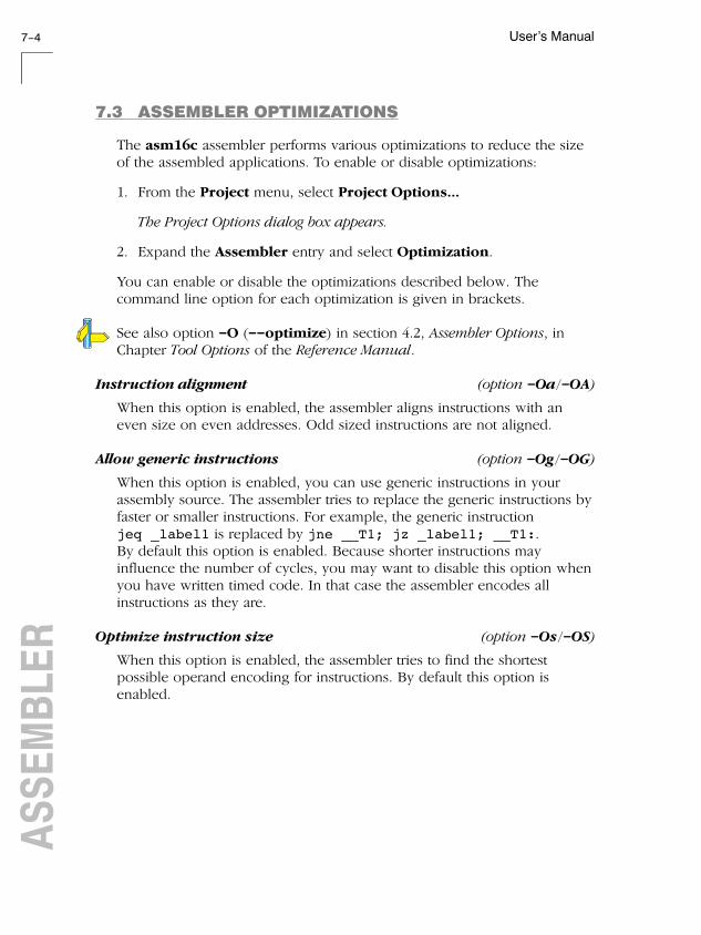
User's Manual7-4ASSEMBLER
7.3 ASSEMBLER OPTIMIZATIONS
The asm16c assembler performs various optimizations to reduce the size
of the assembled applications. To enable or disable optimizations:
1. From the Project menu, select Project Options...
The Project Options dialog box appears.
2. Expand the Assembler entry and select Optimization.
You can enable or disable the optimizations described below. The
command line option for each optimization is given in brackets.
See also option -O (--optimize) in section 4.2, Assembler Options, inChapter Tool Options of the Reference Manual.
Instruction alignment (option -Oa/-OA)
When this option is enabled, the assembler aligns instructions with an
even size on even addresses. Odd sized instructions are not aligned.
Allow generic instructions (option -Og/-OG)
When this option is enabled, you can use generic instructions in your
assembly source. The assembler tries to replace the generic instructions by
faster or smaller instructions. For example, the generic instruction
jeq _label1 is replaced by jne __T1; jz _label1; __T1:.
By default this option is enabled. Because shorter instructions may
influence the number of cycles, you may want to disable this option when
you have written timed code. In that case the assembler encodes all
instructions as they are.
Optimize instruction size (option -Os/-OS)
When this option is enabled, the assembler tries to find the shortest
possible operand encoding for instructions. By default this option is
enabled.
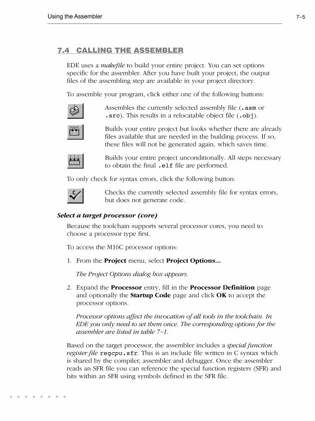
Using the Assembler 7-5
• • • • • • • •
7.4 CALLING THE ASSEMBLER
EDE uses a makefile to build your entire project. You can set options
specific for the assembler. After you have built your project, the output
files of the assembling step are available in your project directory.
To assemble your program, click either one of the following buttons:
Assembles the currently selected assembly file (.asm or
.src). This results in a relocatable object file (.obj).
Builds your entire project but looks whether there are already
files available that are needed in the building process. If so,
these files will not be generated again, which saves time.
Builds your entire project unconditionally. All steps necessary
to obtain the final .elf file are performed.
To only check for syntax errors, click the following button:
Checks the currently selected assembly file for syntax errors,
but does not generate code.
Select a target processor (core)
Because the toolchain supports several processor cores, you need to
choose a processor type first.
To access the M16C processor options:
1. From the Project menu, select Project Options...
The Project Options dialog box appears.
2. Expand the Processor entry, fill in the Processor Definition page
and optionally the Startup Code page and click OK to accept the
processor options.
Processor options affect the invocation of all tools in the toolchain. InEDE you only need to set them once. The corresponding options for theassembler are listed in table 7-1.
Based on the target processor, the assembler includes a special functionregister file regcpu.sfr. This is an include file written in C syntax which
is shared by the compiler, assembler and debugger. Once the assembler
reads an SFR file you can reference the special function registers (SFR) and
bits within an SFR using symbols defined in the SFR file.

User's Manual7-6ASSEMBLER
To access the assembler options
1. From the Project menu, select Project Options...
The Project Options dialog box appears.
2. Expand the Assembler entry, fill in the various pages and click OK to
accept the project options.
The assembler command line equivalences of your EDE selections areshown simultaneously in the Options string box.
The following processor options are available:
EDE options Command line
Processor Definition
Select processor -Ccpu
Target R8C/tiny instead of M16C/60 --r8c
Memory
Internal memory EDE only
Startup Code
Add <project>_cstart.src to your project EDE only
Table 7-1: Processor options
The following assembler options are available:
EDE options Command line
Preprocessing
Define user macro -Dmacro[=def]
Include this file before source -Hfile
Optimization
Optimize speed by means of instruction alignment
Allow generic instructions
Optimize instruction size
-Oa/-OA (= on/off)
-Og/-OG-Os/-OS
Debug
No debug information
Automatic HLL or assembly level debug information
Custom debug information
-gAHLS-gs-gflag
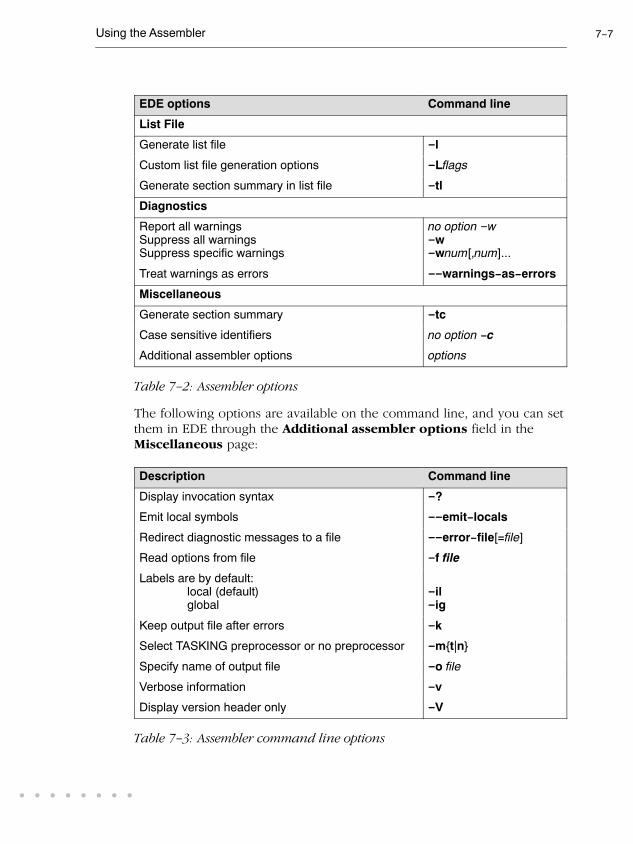
Using the Assembler 7-7
• • • • • • • •
Command lineEDE options
List File
Generate list file -l
Custom list file generation options -Lflags
Generate section summary in list file -tl
Diagnostics
Report all warnings
Suppress all warnings
Suppress specific warnings
no option -w-w-wnum[,num]...
Treat warnings as errors --warnings-as-errors
Miscellaneous
Generate section summary -tc
Case sensitive identifiers no option -c
Additional assembler options options
Table 7-2: Assembler options
The following options are available on the command line, and you can set
them in EDE through the Additional assembler options field in the
Miscellaneous page:
Description Command line
Display invocation syntax -?
Emit local symbols --emit-locals
Redirect diagnostic messages to a file --error-file[=file]
Read options from file -f file
Labels are by default:
local (default)
global
-il-ig
Keep output file after errors -k
Select TASKING preprocessor or no preprocessor -m{t|n}
Specify name of output file -o file
Verbose information -v
Display version header only -V
Table 7-3: Assembler command line options

User's Manual7-8ASSEMBLER
The invocation syntax on the command line is:
asm16c [option]... [file]
The input file must be an assembly source file (.asm or .src).
asm16c test.asm
This assembles the file test.asm for and generates the file test.o
which serves as input for the linker.
For a complete overview of all options with extensive description, see
section 4.2, Assembler Options, of Chapter Tool Options of the ReferenceManual.
7.5 HOW THE ASSEMBLER SEARCHES INCLUDE FILES
When you use include files, you can specify their location in several ways.
The assembler searches the specified locations in the following order:
1. The absolute pathname, if specified in the INCLUDE directive. Or, if no
path or a relative path is specified, the same directory as the source file.
2. The directories that are specified in the Project | Directories dialog (-I
option).
3. The paths which were set during installation. You can still change these
paths.
See section 1.3.1, Configuring the Embedded Development Environmentand environment variable ASM16CINC in section 1.3.2, Configuring theCommand Line Environment, in Chapter Software Installation.
4. The default include directory relative to the installation directory.
7.6 GENERATING A LIST FILE
The list file is an additional output file that contains information about the
generated code. You can also customize the amount and form of
information.
If the assembler generates errors or warnings, these are reported in the list
file just below the source line that caused the error or warning.

Using the Assembler 7-9
• • • • • • • •
To generate a list file
1. From the Project menu, select Project Options...
The Project Options dialog appears.
2. Expand the Assembler entry and select List File.
3. In the List file generation box, select Enable default list file
generation or Custom list file generation options.
4. If you selected Custom, enable the options you want to include in the
list file.
EDE generates a list file for each source file in your project. A list file getsthe same basename as the source file but with extension .lst.
Example on the command line
The following command generates the list file test.lst.
asm16c -l test.src
See section 5.1, Assembler List File Format, in Chapter List File Formats of
the Reference Manual for an explanation of the format of the list file.
7.7 ASSEMBLER ERROR MESSAGES
The assembler produces error messages of the following types:
F Fatal errors
After a fatal error the assembler immediately aborts the assembling
process.
E Errors
Errors are reported, but the assembler continues assembling. No output
files are produced unless you have set the assembler option
--keep-output-files (the resulting output file may be incomplete).

User's Manual7-10ASSEMBLER
W Warnings
Warning messages do not result into an erroneous assembly output file.
They are meant to draw your attention to assumptions of the assembler for
a situation which may not be correct. You can control warnings in the
Assembler | Diagnostics page of the Project | Project Options...
menu (assembler option -w).
Display detailed information on diagnostics
1. In the Help menu, enable the option Show Help on Tool Errors.
2. In the Build tab of the Output window, double-click on an error or
warning message.
A description of the selected message appears.
asm16c --diag=[format:]{all | number,...}
See assembler option --diag in section 4.2, Assembler Options in Chapter
Tool Options of the Reference Manual.

8
USING THE LINKERC
HA
PT
ER

User's Manual8-2LINKER
8
CH
AP
TE
R

Using the Linker 8-3
• • • • • • • •
8.1 INTRODUCTION
The linker lkm16c is a combined linker/locator. The linker phase
combines relocatable object files (.obj files, generated by the assembler),
and libraries into a single relocatable linker object file (.eln). The locator
phase assigns absolute addresses to the linker object file and creates an
absolute object file which you can load into a target processor. From this
point the term linker is used for the combined linker/locator.
The linker takes the following files for input and output:
relocatable object files
linker
relocatable linker object file
lkm16c
.obj
.eln
linker map file .map
error messages .elk
relocatable object library.a
linker script file .lsl
relocatable linker object file .eln memory definition
.mdffile
Motorola S-record
absolute object file
.s
Intel Hex
absolute object file
.hex
ELF/DWARF 2
absolute object file
.elf
Figure 8-1: Linker
This chapter first describes the linking process. Then it describes how to
call the linker and how to use its options. An extensive list of all options
and their descriptions is included in section 4.3, Linker Options, of the
Reference Manual.
To gain even more control over the link process, you can write a script for
the linker. This chapter shortly describes the purpose and basic principles
of the Linker Script Language (LSL) on the basis of an example. A
complete description of the LSL is included in Chapter 7, Linker ScriptLanguage, of the Reference Manual.
The end of the chapter describes how to generate a map file and contains
an overview of the different types of messages of the linker.

User's Manual8-4LINKER
8.2 LINKING PROCESS
The linker combines and transforms relocatable object files (.obj) into a
single absolute object file. This process consists of two phases: the linking
phase and the locating phase.
In the first phase the linker combines the supplied relocatable object files
and libraries into a single relocatable object file. In the second phase, the
linker assigns absolute addresses to the object file so it can actually be
loaded into a target.
Glossary of terms
Term Definition
Absolute object file Object code in which addresses have fixed absolute
values, ready to load into a target.
Address A specification of a location in an address space.
Address space The set of possible addresses. A core can support
multiple spaces, for example in a Harvard architecture
the addresses that identify the location of an instruction
refer to code space, whereas addresses that identify the
location of a data object refer to a data space.
Architecture A description of the characteristics of a core that are of
interest for the linker. This encompasses the logical
address space(s) and the internal bus structure. Given
this information the linker can convert logical addresses
into physical addresses.
Copy table A section created by the linker. This section contains
data that specifies how the startup code initializes the
data sections. For each section the copy table contains
the following fields:
- action: defines whether a section is copied or zeroed
- destination: defines the section's address in RAM
- source: defines the sections address in ROM
- length: defines the size of the section in MAUs
of the destination space
Core An instance of a core architecture.
Derivative The design of a processor. A description of one or more
cores including internal memory and any number of
buses.
Library Collection of relocatable object files. Usually each
object file in a library contains one symbol definition
(for example, a function).

Using the Linker 8-5
• • • • • • • •
DefinitionTerm
Logical address An address as encoded in an instruction word, an
address generated by a core (CPU).
LSL file The set of linker script files that are passed to the linker.
MAU Minimum Addressable Unit. For a given processor the
number of bits loaded between an address and the next
address. This is not necessarily a byte or a word.
Object code The binary machine language representation of the
C source.
Physical address An address generated by the memory system.
Processor An instance of a derivative. Usually implemented as a
(custom) chip, but can also be implemented in an
FPGA, in which case the derivative can be designed by
the developer.
Relocatable object
file
Object code in which addresses are represented by
symbols and thus relocatable.
Relocation The process of assigning absolute addresses.
Relocation
information
Information about how the linker must modify the
machine code instructions when it relocates addresses.
Section A group of instructions and/or data objects that occupy
a contiguous range of addresses.
Section attributes Attributes that define how the section should be linked
or located.
Target The hardware board on which an application is
executing. A board contains at least one processor.
However, a complex target may contain multiple
processors and external memory that may be shared
between processors.
Unresolved
reference
A reference to a symbol for which the linker did not find
a definition yet.
Table 8-1: Glossary of terms

User's Manual8-6LINKER
8.2.1 PHASE 1: LINKING
The linker takes one or more relocatable object files and/or libraries as
input. A relocatable object file, as generated by the assembler, contains the
following information:
• Header information: Overall information about the file, such as the
code size, name of the source file it was assembled from, and creation
date.
• Object code: Binary code and data, divided into various named
sections. Sections are contiguous chunks of code or data that have to
be placed in specific parts of the memory. The program addresses start
at zero for each section in the object file.
• Symbols: Some symbols are exported - defined within the file for use
in other files. Other symbols are imported - used in the file but not
defined (external symbols). Generally these symbols are names of
routines or names of data objects.
• Relocation information: A list of places with symbolic references that
the linker has to replace with actual addresses. When in the code an
external symbol (a symbol defined in another file or in a library) is
referenced, the assembler does not know the symbol's size and
address. Instead, the assembler generates a call to a preliminary
relocatable address (usually 0000), while stating the symbol name.
• Debug information: Other information about the object code that is
used by a debugger. The assembler optionally generates this
information and can consist of line numbers, C source code, local
symbols and descriptions of data structures.
The linker resolves the external references between the supplied
relocatable object files and/or libraries and combines the supplied
relocatable object files into a single relocatable linker object file.
The linker starts its task by scanning all specified relocatable object files
and libraries. If the linker encounters an unresolved symbol, it remembers
its name and continues scanning. The symbol may be defined elsewhere
in the same file, or in one of the other files or libraries that you specified
to the linker. If the symbol is defined in a library, the linker extracts the
object file with the symbol definition from the library. This way the linker
collects all definitions and references of all of the symbols.

Using the Linker 8-7
• • • • • • • •
With this information, the linker combines the object code of all
relocatable object files. The linker combines sections with the same section
name and attributes into single sections, starting each section at address
zero. The linker also substitutes (external) symbol references by
(relocatable) numerical addresses where possible. At the end of the linking
phase, the linker either writes the results to a file (a single relocatable
object file) or keeps the results in memory for further processing during
the locating phase.
The resulting file of the linking phase is a single relocatable object file
(.eln). If this file contains unresolved references, you can link this file
with other relocatable object files (.obj) or libraries (.a) to resolve the
remaining unresolved references.
With the linker command line option --link-only, you can tell the linker
to only perform this linking phase and skip the locating phase. The linker
complains if any unresolved references are left.
8.2.2 PHASE 2: LOCATING
In the locating phase, the linker assigns absolute addresses to the object
code, placing each section in a specific part of the target memory. The
linker also replaces references to symbols by the actual address of those
symbols. The resulting file is an absolute object file which you can actually
load into a target memory. Optionally, when the resulting file should be
loaded into a ROM device the linker creates a so-called copy table section
which is used by the startup code to initialize the data sections.
Code modification
When the linker assigns absolute addresses to the object code, it needs to
modify this code according to certain rules or relocation expressions toreflect the new addresses. These relocation expressions are stored in the
relocatable object file. Consider the following snippet of x86 code that
moves the contents of variable a to variable b via the eax register:
A1 3412 0000 mov a,%eax (a defined at 0x1234, byte reversed)A3 0000 0000 mov %eax,b (b is imported so the instruction refers to 0x0000 since its location is unknown)
Now assume that the linker links this code so that the section in which a
is located is relocated by 0x10000 bytes, and b turns out to be at 0x9A12.
The linker modifies the code to be:

User's Manual8-8LINKER
A1 3412 0100 mov a,%eax (0x10000 added to the address)A3 129A 0000 mov %eax,b (0x9A12 patched in for b)
These adjustments affect instructions, but keep in mind that any pointers
in the data part of a relocatable object file have to be modified as well.
Output formats
The linker can produce its output in different file formats. The default
ELF/DWARF2 format (.elf) contains an image of the executable code and
data, and can contain additional debug information. The Intel-Hex format
(.hex) and Motorola S-record format (.s) only contain an image of the
executable code and data. You can specify a format with the options -o
(--output) and -c (--chip-output).
Controlling the linker
Via a so-called linker script file you can gain complete control over the
linker. The script language used to describe these features is called the
Linker Script Language (LSL). You can define:
• The types of memory that are installed in the embedded target system:
To assign locations to code and data sections, the linker must know
what memory devices are actually installed in the embedded target
system. For each physical memory device the linker must know its
start-address, its size, and whether the memory is read-write accessible
(RAM) or read-only accessible (ROM).
• How and where code and data should be placed in the physical
memory:
Embedded systems can have complex memory systems. If for example
on-chip and off-chip memory devices are available, the code and data
located in internal memory is typically accessed faster and with
dissipating less power. To improve the performance of an application,
specific code and data sections should be located in on-chip memory.
By writing your own LSL file, you gain full control over the locating
process.
• The underlying hardware architecture of the target processor.

Using the Linker 8-9
• • • • • • • •
To perform its task the linker must have a model of the underlying
hardware architecture of the processor you are using. For example the
linker must know how to translate an address used within the object
file (a logical address) into an offset in a particular memory device
(a physical address). In most linkers this model is hard coded in the
executable and can not be modified. For the lkm16c linker this
hardware model is described in the linker script file. This solution is
chosen to support configurable cores that are used in system-on-chip
designs.
When you want to write your own linker script file, you can use the
standard linker script files with architecture descriptions delivered with the
product.
See also section 8.6, Controlling the Linker with a Script.
8.2.3 LINKER OPTIMIZATIONS
During the linking and locating phase, the linker looks for opportunities to
optimize the object code. Both code size and execution speed can be
optimized. To enable or disable optimizations:
1. From the Project menu, select Project Options...
The Project Options dialog box appears.
2. Expand the Linker entry and select Optimization.
You can enable or disable the optimizations described below. The
command line option for each optimization is given in brackets.
See also option -O (--optimize) in section 4.3, Linker Options, in Chapter
Tool Options of the Reference Manual.
First fit decreasing (option -Ol/-OL)
When the physical memory is fragmented or when address spaces are
nested it may be possible that a given application cannot be located
although the size of the available physical memory is larger than the sum
of the section sizes. Enable the first-fit-decreasing optimization when this
occurs and re-link your application.

User's Manual8-10LINKER
The linker's default behavior is to place sections in the order that is
specified in the LSL file. This also applies to sections within an unrestricted
group. If a memory range is partially filled and a section must be located
that is larger than the remainder of this range, then the section and all
subsequent sections are placed in a next memory range. As a result of this
gaps occur at the end of a memory range.
When the first-fit-decreasing optimization is enabled the linker will first
place the largest sections in the smallest memory ranges that can contain
the section. Small sections are located last and can likely fit in the
remaining gaps.
Copy table compression (option -Ot/-OT)
The startup code initializes the application's data areas. The information
about which memory addresses should be zeroed and which memory
ranges should be copied from ROM to RAM is stored in the copy table.
When this optimization is enabled the linker will try to locate sections in
such a way that the copy table is as small as possible thereby reducing the
application's ROM image.
This optimization reduces both memory and startup speed.
Compress ROM image (option -Oz/-OZ)
Reduce the size of the application's ROM image by compressing the ROM
image of initialized data sections. At application startup time the ROM
image is decompressed and copied to RAM.
Delete unreferenced sections (option -Oc/-OC)
This optimization removes unused sections from the resulting object file.
Because debug information normally refers to all sections, this
optimization has no effect until you compile your project without debug
information or use linker option --strip-debug to remove the debug
information.
Delete duplicate code sections (option -Ox/-OX)
Delete duplicate data sections (option -Oy/-OY)
These two optimizations remove code and constant data that is defined
more than once, from the resulting object file.

Using the Linker 8-11
• • • • • • • •
8.3 CALLING THE LINKER
EDE uses a makefile to build your entire project. This means that you
cannot run only the linker. However, you can set options specific for the
linker. After you have build your project, the output files of the linking
step are available in your project directory, unless you specified an
alternative output directory in the Build Options dialog.
To link your program, click either one of the following buttons:
Builds your entire project but only updates files that are
out-of-date or have been changed since the previous build,
which saves time.
Builds your entire project unconditionally. All steps necessary
to obtain the final .elf file are performed.
To get access to the linker options:
1. From the Project menu, select Project Options...
The Project Options dialog box appears.
2. Expand the Linker entry. Select the subentries and set the options in
the various pages.
The command line variant is shown simultaneously.

User's Manual8-12LINKER
The following linker options are available:
EDE options Command line
Output Format
Output formats -o[filename][:format[:addr_size][,space]]
-c[basename]:format[:addr_size]
Libraries
Link default C libraries -lx
Rescan libraries to solve unresolved exernals --no-rescan
Link case sensitive (required for C language) no option--case-insensitive
Optimization
Use a 'first fit decreasing' algorithm
Use copy table compression
Compress ROM image
Delete unreferenced sections
Delete duplicate code
Delete duplicate constant data
-Ol/-OL (= on/off)
-Ot/-OT-Oz/-OZ-Oc/-OC-Ox/-OX-Oy/-OY
Map File
Generate a map file (.map) -M
Suboptions for the Generate a map file option -mflags
Warnings
Report all warnings
Suppress all warnings
Suppress specific warnings
no option -w-w-wnum[,num]...
Treat warnings as errors --warnings-as-errors
Miscellaneous
Use standard copy-table for initialization no option -i
Strip symbolic debug information -S
Dump processor and memory info from LSL file --lsl-dump[=file]
Select linker script file -dfile,...
Additional linker options options
Table 8-2: Linker options
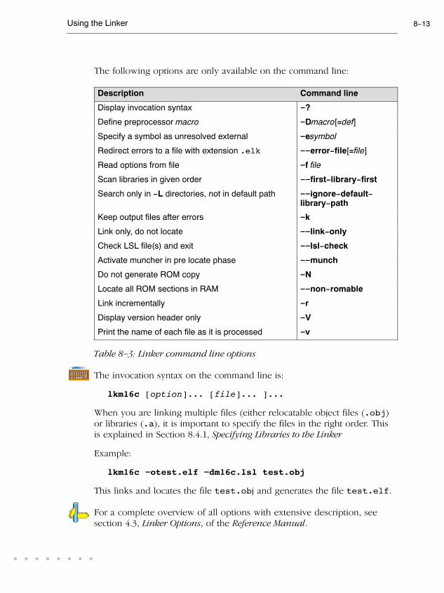
Using the Linker 8-13
• • • • • • • •
The following options are only available on the command line:
Description Command line
Display invocation syntax -?
Define preprocessor macro -Dmacro[=def]
Specify a symbol as unresolved external -esymbol
Redirect errors to a file with extension .elk --error-file[=file]
Read options from file -f file
Scan libraries in given order --first-library-first
Search only in -L directories, not in default path --ignore-default-library-path
Keep output files after errors -k
Link only, do not locate --link-only
Check LSL file(s) and exit --lsl-check
Activate muncher in pre locate phase --munch
Do not generate ROM copy -N
Locate all ROM sections in RAM --non-romable
Link incrementally -r
Display version header only -V
Print the name of each file as it is processed -v
Table 8-3: Linker command line options
The invocation syntax on the command line is:
lkm16c [option]... [file]... ]...
When you are linking multiple files (either relocatable object files (.obj)
or libraries (.a), it is important to specify the files in the right order. This
is explained in Section 8.4.1, Specifying Libraries to the Linker
Example:
lkm16c -otest.elf -dm16c.lsl test.obj
This links and locates the file test.obj and generates the file test.elf.
For a complete overview of all options with extensive description, see
section 4.3, Linker Options, of the Reference Manual.

User's Manual8-14LINKER
8.4 LINKING WITH LIBRARIES
There are two kinds of libraries: system libraries and user libraries.
System library
The lib directory of the toolchain contains subdirectories with separate
system libraries for the M16C and the R8C. An overview of the system
libraries is given in the following tables.
Library to link Description
libcs.a
libcm.a
libcl.a
C library for small, medium or large memory model
(Some functions require the floating-point library. Also
includes the startup code.)
libcss.a
libcms.a
libcls.a
Single precision C library for small, medium or large memory
model (compiler option -F)
(Some functions require the floating-point library. Also
includes the startup code.)
libfps.a
libfpm.a
libfpl.a
Floating-point library (non-trapping) for each model
libfpst.a
libfpmt.a
libfplt.a
Floating-point library (trapping) for each model
(Control program option --fp-trap)
librts.a
librtm.a
librtl.a
Run-time library for each model
Table 8-4: Overview of M16C libraries
Library to link Description
libc.a C library
(Some functions require the floating-point library. Also
includes the startup code.)
libcs.a Single precision C library (compiler option -F)
(Some functions require the floating-point library. Also
includes the startup code.)
libfp.a Floating-point library (non-trapping)
libfpt.a Floating-point library (trapping)
(Control program option --fp-trap)
librt.a Run-time library
Table 8-5: Overview of R8C libraries

Using the Linker 8-15
• • • • • • • •
For more information on these libraries see section 3.14, Libraries, inChapter C Language.
User library
You can also create your own libraries. Section 9.4, Archiver, in Chapter
Using the Utilities, describes how you can use the archiver to create your
own library with object modules. To link user libraries, specify their
filenames on the command line.
8.4.1 SPECIFYING LIBRARIES TO THE LINKER
In EDE you can specify both system and user libraries.
Link a system library with EDE
To specify to link the default C libraries:
1. From the Project menu, select Project Options...
The Project Options dialog box appears.
2. Expand the Linker entry and select Libraries.
3. Select Link default C libraries.
4. Click OK to accept the linker options.
When you want to link system libraries from the command line, you must
specify this with the linker option -l. With the option -lcl you specify the
system library libcl.a. For example:
lkm16c -lcl start.obj
Link a user library in EDE
To specify your own libraries, you have to add the library files to your
project:
1. From the Project menu, select Properties...
The Project Properties dialog box appears.
2. In the Members tab, click on the Add existing files to project
button.

User's Manual8-16LINKER
3. Select the libraries you want to add and click Open.
4. Click OK to accept the new project settings.
The invocation syntax on the command line is for example:
lkm16c start.obj mylib.a
If the library resides in a subdirectory, specify that directory with the
library name:
lkm16c start.obj mylibs\mylib.a
Library order
The order in which libraries appear on the command line is important. By
default the linker processes object files and libraries in the order in which
they appear on the command line. Therefore, when you use a weak
symbol construction, like printf, in an object file or your own library,
you must position this object/library before the C library.
With the option --first-library-first you can tell the linker to scan the
libraries from left to right, and extract symbols from the first library where
the linker finds it. This can be useful when you want to use newer
versions of a library routine.
Example:
lkm16c --first-library-first a.a test.obj b.a
If the file test.obj calls a function which is both present in a.a and
b.a, normally the function in b.a would be extracted. With this option
the linker first tries to extract the symbol from the first library a.a.
8.4.2 HOW THE LINKER SEARCHES LIBRARIES
System libraries
You can specify the location of system libraries (specified with option -l)
in several ways. The linker searches the specified locations in the
following order:
1. The linker first looks in the directories that are specified in the
Directories dialog (-L option). If you specify the -L option without a
pathname, the linker stops searching after this step.

Using the Linker 8-17
• • • • • • • •
2. When the linker did not find the library (because it is not in the specified
library directory or because no directory is specified), it looks which paths
were set during installation. You can still change these paths if you like.
See environment variables LIBM16C in section 1.3.2, Configuring theCommand Line Environment, in Chapter Software Installation.
3. When the linker did not find the library, it tries the default lib directory
relative to the installation directory.
User library
If you use your own library, the linker searches the library in the current
directory only.
8.4.3 HOW THE LINKER EXTRACTS OBJECTS FROM
LIBRARIES
A library built with arm16c always contains an index part at the beginning
of the library. The linker scans this index while searching for unresolved
externals. However, to keep the index as small as possible, only the
defined symbols of the library members are recorded in this area.
When the linker finds a symbol that matches an unresolved external, the
corresponding object file is extracted from the library and is processed.
After processing the object file, the remaining library index is searched. If
after a complete search of the library unresolved externals are introduced,
the library index will be scanned again. After all files and libraries are
processed, and there are still unresolved externals and you did not specify
the linker option --no-rescan, all libraries are rescanned again. This way
you do not have to worry about the library order. However, this
rescanning does not work for 'weak symbols'. If you use a weak symbol
construction, like printf, in an object file or your own library, you must
position this object/library before the C library
The -v option shows how libraries have been searched and which objects
have been extracted.

User's Manual8-18LINKER
Resolving symbols
If you are linking from libraries, only the objects that contain symbol
definition(s) to which you refer, are extracted from the library. This implies
that if you invoke the linker like:
lkm16c mylib.a
nothing is linked and no output file will be produced, because there are
no unresolved symbols when the linker searches through mylib.a.
It is possible to force a symbol as external (unresolved symbol) with the
option -e:
lkm16c -e main mylib.a
In this case the linker searches for the symbol main in the library and (if
found) extracts the object that contains main. If this module contains new
unresolved symbols, the linker looks again in mylib.a. This process
repeats until no new unresolved symbols are found.
8.5 INCREMENTAL LINKING
With the M16C linker lkm16c it is possible to link incrementally.Incremental linking means that you link some, but not all .obj modules
to a relocatable object file .eln. In this case the linker does not perform
the locating phase. With the second invocation, you specify both new
.obj files and the .eln file you had created with the first invocation.
Incremental linking is only possible on the command line.
lkm16c -r test1.obj -otest.eln
lkm16c test2.obj test.eln
This links the file test1.obj and generates the file test.eln. This file is
used again and linked together with test2.obj to create the file
task1.elf (the default name if no output filename is given in the default
ELF/DWARF 2 format).
With incremental linking it is normal to have unresolved references in the
output file until all .obj files are linked and the final .eln or .elf file
has been reached. The option -r for incremental linking also suppresses
warnings and errors because of unresolved symbols.

Using the Linker 8-19
• • • • • • • •
8.6 CONTROLLING THE LINKER WITH A SCRIPT
With the options on the command line you can control the linker's
behavior to a certain degree. From EDE it is also possible to determine
where your sections will be located, how much memory is available,
which sorts of memory are available, and so on. EDE passes these locating
directions to the linker via a script file. If you want even more control over
the locating process you can supply your own script.
The language for the script is called the Linker Script Language, or shortly
LSL. You can specify the script file to the linker, which reads it and locates
your application exactly as defined in the script. If you do not specify your
own script file, the linker always reads a standard script file which is
supplied with the toolchain.
8.6.1 PURPOSE OF THE LINKER SCRIPT LANGUAGE
The Linker Script Language (LSL) serves three purposes:
1. It provides the linker with a definition of the target's core architecture.
This definition is supplied with the toolchain.
2. It provides the linker with a specification of the memory attached to
the target processor.
3. It provides the linker with information on how your application should
be located in memory. This gives you, for example, the possibility to
create overlaying sections.
The linker accepts multiple LSL files. You can use the specifications of the
M16C and R8C architectures that Altium has supplied in the include.lsl
directory. Do not change these files.
If you use a different memory layout than described in the LSL file
supplied for the target core, you must specify this in a separate LSL file
and pass both the LSL file that describes the core architecture and your LSL
file that contains the memory specification to the linker. Next you may
want to specify how sections should be located and overlaid. You can do
this in the same file or in another LSL file.
LSL has its own syntax. In addition, you can use the standard ANSI C
preprocessor keywords because the linker sends the script file first to the
C preprocessor before it starts interpreting the script.
User's Manual8-20LINKER
The complete syntax is described in Chapter 7, Linker Script Language, inthe Reference Manual.
8.6.2 EDE AND LSL
In EDE you can specify the size of the stack and heap; the physical
memory attached to the processor; identify that particular address ranges
are reserved; and specify which sections are located where in memory.
EDE translates your input into an LSL file that is stored in the project
directory under the name project.lsl and passes this file to the linker.
If you want to learn more about LSL you can inspect the generated file
project.lsl.
To change the LSL settings
1. From the Project menu, select Project Options...
The Project Options dialog box appears.
2. Expand the Processor entry and select Memory.
3. Make your changes.
4. Also make your changes, if necessary, in the pages Sections,
Reserved Areas and/or Stack/Heap in the Linker entry.
Each time you close the Project Options dialog the file project.lsl is
updated and you can immediately see how your settings are encoded in
LSL.
Note that EDE supports ChromaCoding (applying color coding to text) and
template expansion when you edit LSL files.
Specify your own LSL file
If you want to write your own linker script file, you can use the EDE
generated file project.lsl as an example. Specify this file to EDE as
follows:
1. From the Project menu, select Project Options...
The Project Options dialog box appears.
2. Expand the Linker entry and select Miscellaneous.
Using the Linker 8-21
• • • • • • • •
3. Select Use project specific linker script file and add your own file in
the edit field.
8.6.3 STRUCTURE OF A LINKER SCRIPT FILE
A script file consists of several definitions. The definitions can appear in
any order.
The architecture definition (required)
In essence an architecture definition describes how the linker should
convert logical addresses into physical addresses for a given type of core.
If the core supports multiple address spaces, then for each space the linker
must know how to perform this conversion. In this context a physical
address is an offset on a given internal or external bus. Additionally the
architecture definition contains information about items such as the
(hardware) stack and the interrupt vector table.
This specification is normally written by Altium. For the M16C core
architecture, a separate LSL file is provided m16c.lsl. For the R8C core
architecture, a separate LSL file is provided r8c.lsl.
The architecture definition of the LSL file should not be changed by you
unless you also modify the core's hardware architecture. If the LSL file
describes a multi-core system an architecture definition must be available
for each different type of core.
The derivative definition (required)
The derivative definition describes the configuration of the internal
(on-chip) bus and memory system. Basically it tells the linker how to
convert offsets on the buses specified in the architecture definition into
offsets in internal memory. A derivative definition must be present in an
LSL file. Microcontrollers and DSPs often have internal memory and I/O
sub-systems apart from one or more cores. The design of such a chip is
called a derivative.
When you design an FPGA together with a PCB, the components on the
FPGA become part of the board design and there is no need to distinguish
between internal and external memory. For this reason you probably do
not need to work with derivative definitions at all. There are, however,
two situations where derivative definitions are useful:

User's Manual8-22LINKER
1. When you re-use an FPGA design for several board designs it may be
practical to write a derivative definition for the FPGA design and
include it in the project LSL file.
2. When you want to use multiple cores of the same type, you must
instantiate the cores in a derivative definition, since the linker
automatically instantiates only a single core for an unused architecture.
The processor definition
The processor definition describes an instance of a derivative. A processor
definition is only needed in a multi-processor embedded system. It allows
you to define multiple processors of the same type.
If for a derivative 'A' no processor is defined in the LSL file, the linker
automatically creates a processor named 'A' of derivative 'A'. This is why
for single-processor applications it is enough to specify the derivative in
the LSL file, for example with -dm16c.lsl.
The memory and bus definitions (optional)
Memory and bus definitions are used within the context of a derivative
definition to specify internal memory and on-chip buses. In the context of
a board specification the memory and bus definitions are used to define
external (off-chip) memory and buses. Given the above definitions the
linker can convert a logical address into an offset into an on-chip or
off-chip memory device.
The board specification
The processor definition and memory and bus definitions together form a
board specification. LSL provides language constructs to easily describe
single-core and heterogeneous or homogeneous multi-core systems. The
board specification describes all characteristics of your target board's
system buses, memory devices, I/O sub-systems, and cores that are of
interest to the linker. Based on the information provided in the board
specification the linker can for each core:
• convert a logical address to an offset within a memory device
• locate sections in physical memory
• maintain an overall view of the used and free physical memory within
the whole system while locating

Using the Linker 8-23
• • • • • • • •
The section layout definition (optional)
The optional section layout definition enables you to exactly control
where input sections are located. Features are provided such as: the ability
to place sections at a given address, to place sections in a given order, and
to overlay code and/or data sections.
Example: Skeleton of a Linker Script File
A linker script file that defines a derivative "X'" based on the M16C
architecture, its external memory and how sections are located in memory,
may have the following skeleton:
architecture M16C
{
// Specification of the M16C core architecture.
// Written by Altium.
}
derivative X // derivative name is arbitrary
{
// Specification of the derivative.
// Written by Altium.
core M16C // always specify the core
{
architecture = M16C;
}
bus data_bus // internal bus
{
// maps to data_bus in "M16C" core
}
// internal memory
}
processor proc1 // processor name is arbitrary
{
derivative = X;
// You can omit this part, except if you use a
// multi-core system.
}

User's Manual8-24LINKER
memory ext_name
{
// external memory definition
}
section_layout proc1:M16C:near // section layout
{
// section placement statements
// sections are located in address space 'near'
// of core 'M16C' of processor 'proc1'
}
8.6.4 THE ARCHITECTURE DEFINITION
Although you will probably not need to program the architecture
definition (unless you are building your own processor core) it helps to
understand the Linker Script Language and how the definitions are
interrelated.
Within an architecture definition the characteristics of a target processor
core that are important for the linking process are defined. These include:
• space definitions: the logical address spaces and their properties
• bus definitions: the I/O buses of the core architecture
• mappings: the address translations between logical address spaces, the
connections between logical address spaces and buses and the address
translations between buses
Address spaces
A logical address space is a memory range for which the core has a
separate way to encode an address into instructions. Most microcontrollers
and DSPs support multiple address spaces. For example, the M16C has
separate spaces for byte-addressable data and bit-addressable data.
Normally, the size of an address space is to 2N, with N the number of bits
used to encode the addresses.
The relation of an address space with another address space can be one of
the following:
• one space is a subset of the other. These are often used for "small"
absolute, and relative addressing.

Using the Linker 8-25
• • • • • • • •
• the addresses in the two address spaces represent different locations so
they do not overlap. This means the core must have separate sets of
address lines for the address spaces. For example, in Harvard
architectures we can identify at least a code and a data memory space.
Address spaces (even nested) can have different minimal addressable units
(MAU), alignment restrictions, and page sizes.
The M16C architecture in LSL notation
The best way to program the architecture definition, is to start with a
drawing. The following figure shows a part of the M16C architecture:
0
1M
64k
space far
space near
bus data_bus
id = 1
mau = 8
id = 2
mau = 8
mau = 8
width=8
Figure 8-2: Scheme of (part of) the M16C architecture
The figure shows two address spaces called near, and far. The address
space near is a subset of the address space far. All address spaces have
attributes like a number that identifies the logical space (id), a MAU size
and an alignment. In LSL notation the definition of these address spaces
looks as follows:
space near
{
id = 1;
mau = 8;
map (src_offset=0x00000, dest_offset=0x00000,
size=64k, dest=space:far);
}
space far
{
id = 2;
mau = 8;
map (src_offset=0x00000, dest_offset=0x00000,
size=1M, dest=bus:data_bus);
}

User's Manual8-26LINKER
The keyword map corresponds with the arrows in the drawing. You can
map:
• address space => address space
• address space => bus
• memory => bus (not shown in the drawing)
• bus => bus (not shown in the drawing)
Next the internal bus, named data_bus must be defined in LSL:
bus data_bus
{
mau = 8;
width = 8; // there are 8 data lines on the bus
}
This completes the LSL code in the architecture definition. Note that all
code above goes into the architecture definition, thus between:
architecture M16C
{
All code above goes here.
}
8.6.5 THE DERIVATIVE DEFINITION
Although you will probably not need to program the derivative definition
(unless you are using multiple cores) the description below helps to
understand the Linker Script Language and how the definitions are
interrelated.
A derivative is the design of a processor, as implemented on a chip (or
FPGA). It comprises one or more cores and on-chip memory. The
derivative definition includes:
• core definition: an instance of a core architecture
• bus definition: the I/O buses of the core architecture
• memory definitions: internal (or on-chip) memory

Using the Linker 8-27
• • • • • • • •
Core
Each derivative must have at least one core and each core must have a
specification of its core architecture. This core architecture must be defined
somewhere in the LSL file(s).
core M16C
{
architecture = M16C;
}
Bus
Each derivative can contain a bus definition for connecting external
memory. In this example, the bus data_bus maps to the bus data_bus
defined in the architecture definition of core M16C:
bus data_bus
{
mau = 8;
width = 8;
map (dest=bus:M16C:data_bus, dest_offset=0, size=256);
}
Memory
Memory is usually described in a separate memory definition, but you can
specify on-chip memory for a derivative. For example:
memory internal_ram
{
type = ram;
size = 16k;
mau = 8;
map(src_offset=0x0000, dest_offset=0x0000,
size=16k, dest=bus:M16C:data_bus);
}
This completes the LSL code in the derivative definition. Note that all code
above goes into the derivative definition, thus between:
derivative X // name of derivative
{
All code above goes here.
}

User's Manual8-28LINKER
If you want to create a custom derivative and you want to use EDE to
select sections, the derivative must be called "M16C", since EDE uses this
name in the generated LSL file. If you want to specify external memory in
EDE, the custom derivative must contain a bus named "data_bus" for the
same reason. In EDE you have to define a target processor in the
Processor pages of the Project | Project Options dialog.
8.6.6 THE MEMORY DEFINITION
Once the core architecture is defined in LSL, you may want to extend the
processor with memory. You need to specify the location and size of the
physical external memory devices in the target system.
The principle is the same as defining the core's architecture but now you
need to fill the memory definition:
memory name
{
memory definitions.
}
0
1M
8k
space far
space near
bus data_bus
id = 1
mau = 8
id = 2
mau = 8
mau = 8
width=816k
0
memory iram
mau = 8
256k
memory irom
0
mau = 8
1k
0mau = 8
memory my_nvram
Figure 8-3: Adding external memory to the M16C architecture
Suppose your embedded system has 16k of RAM, named iram., 1k of
non-volatile RAM called my_nvram and 256k of ROM, named irom (see
figure above). The memories are connected to the bus data_bus. In LSL
this looks like:

Using the Linker 8-29
• • • • • • • •
memory iram
{
type = ram;
size = 16k;
mau = 8;
map(src_offset=0x0000, dest_offset=0x0400,
size=16k, dest=bus:M16C:data_bus);
}
The memory my_nvram is connected to the bus with an offset of 0x5000:
memory my_nvram
{
type = ram;
size = 1k;
mau = 8;
map(src_offset=0x0000, dest_offset=0x5000,
size=1k, dest=bus:M16C:data_bus);
}
The memory irom is connected to the bus with an offset of 0xC0000:
memory irom
{
type = rom;
size = 256k;
mau = 8;
map(src_offset=0x0000, dest_offset=0xc0000,
size=256k, dest=bus:M16C:data_bus);
}
If you use a different memory layout than described in the LSL file
supplied for the target core, you can specify this in EDE or you can specify
this in a separate LSL file and pass both the LSL file that describes the core
architecture and your LSL file that contains the memory specification to the
linker.
In order to bypass the default memory setup, your memory LSL file must
contain a #define __NODEFAULTMEM, and you must specify this file
before the core architecture LSL file.
Adding memory using EDE
In EDE you can only specify external memory if the processor does not
run in single chip mode.
1. From the Project menu, select Project Options...
The Project Options dialog box appears.
2. Expand the Processor entry and select Processor Definition.

User's Manual8-30LINKER
3. Select Memory Expansion mode or Microprocessor mode or select
-- User Defined -- in the Select processor box for a user defined
processor.
4. Open the Memory page.
5. In the External Memory box add your memory (for example
my_nvram), by specifying the type, name, start address and size.
8.6.7 THE SECTION LAYOUT DEFINITION: LOCATING
SECTIONS
Once you have defined the internal core architecture and optional
memory, you can actually define where your application must be located
in the physical memory.
During compilation, the compiler divides the application into sections.
Sections have a name, an indication in which address space it should be
located and attributes like writable or read-only.
In the section layout definition you can exactly define how input sections
are placed in address spaces, relative to each other, and what their
absolute run-time and load-time addresses will be. To illustrate section
placement the following example of a C program is used:
Example: section propagation through the toolchain
To illustrate section placement, the following example of a C program
(bat.c) is used. The program saves the number of times it has been
executed in battery back-upped memory, and prints the number.
#define BATTERY_BACKUP_TAG 0xa5f0
#include <stdio.h>
int uninitialized_data;
int initialized_data = 1;
#pragma renamesect DA "non_volatile" noclear
int battery_backup_tag;
int battery_backup_invok;
#pragma endrenamesect DA

Using the Linker 8-31
• • • • • • • •
void main (void)
{
if (battery_backup_tag != BATTERY_BACKUP_TAG )
{
// battery back-upped memory area contains invalid data
// initialize the memory
battery_backup_tag = BATTERY_BACKUP_TAG;
battery_backup_invok = 0;
}
printf( "This application has been invoked %d times\n",
battery_backup_invok++);
}
The compiler assigns names and attributes to sections. With the #pragma
renamesect DA "name" the compiler's default section naming
convention is overruled and a section with the name
non_volatile_CLR_DA is defined. In this section the battery
back-upped data is stored.
By default the compiler creates the section bat_CLR_DA, data, clear
(a section with the name bat_CLR_DA carrying section attributes "data"
and "clear") to store uninitialized data objects. The section attributes tell
the linker to locate the section in address space data and that the section
content should be filled with zeros at startup.
As a result of the #pragma renamesect DA "non_volatile"
noclear, the data objects between the pragma pair are placed in
non_volatile_CLR_DA, data, noclear. Note that because battery
back-upped sections should not be cleared we used the "noclear"
attribute.
The generated assembly may look like:
extern (code)_printf
extern (code)___printf_int
extern (code)__START
defsect "bat_CO", code
sect "bat_CO"
global _main

User's Manual8-32LINKER
; Function _main
_main: type func
cmp.w #42480, _battery_backup_tag
jeq _2
.
.
jsr _printf
rts
size _main, $-_main
; End of function
; End of section
defsect "bat_CLR_DA", data, clear
sect "bat_CLR_DA"
global _uninitialized_data
_uninitialized_data: type object
size _uninitialized_data, 2
ds 2
; End of section
defsect "bat_INI_DA", data, init
sect "bat_INI_DA"
global _initialized_data
_initialized_data: type object
size _initialized_data, 2
dw 1
; End of section
defsect "non_volatile_CLR_DA", data, noclear
sect "non_volatile_CLR_DA"
global _battery_backup_tag
_battery_backup_tag: type object
size _battery_backup_tag, 2
ds 2
global _battery_backup_invok
_battery_backup_invok: type object
size _battery_backup_invok, 2
ds 2
; End of section
sect "bat_INI_DA"
__1_ini: type object
size __1_ini, 44
db 84, 104, 105, 115, 32, 97, 112, 112, 108, 105
db 99, 97, 116, 105, 111, 110, 32, 104, 97, 115
db 32, 98, 101, 101, 110, 32, 105, 110, 118, 111
db 107, 101, 100, 32, 37, 100, 32, 116, 105, 109
db 101, 115, 10, 0
; This application has been invoked %d times\n
; Module end

Using the Linker 8-33
• • • • • • • •
Section placement
The number of invocations of the example program should be saved in
non-volatile (battery back-upped) memory. This is the memory my_nvram
from the example in the previous section.
To control the locating of sections, you need to write one or more section
definitions in the LSL file. At least one for each address space where you
want to change the default behavior of the linker. In our example, we
need to locate sections in the address space near:
section_layout ::near
{
Section placement statements
}
To locate sections, you must create a group in which you select sections
from your program. For the battery back-up example, we need to define
one group, which contains the section non_volatile_CLR_DA. All other
sections are located using the defaults specified in the architecture
definition. Section non_volatile_CLR_DA should be placed in
non-volatile ram. To achieve this, the run address refers to our
non-volatile memory called my_nvram:
group ( ordered, run_addr = mem:my_nvram )
{
select "non_volatile_CLR_DA";
}
Section placement from EDE
To specify the above settings using EDE, follow these steps:
1. From the Project menu, select Project Options...
The Project Options dialog box appears.
2. Expand the Linker entry and select Sections.
Here you can specify where sections are located in memory.
3. In the Section type field, select Near Data.
4. In the Section name field, enter non_volatile_CLR_DA.
5. In the Absolute address field, enter mem:my_nvram
6. In the Section attr field, select Code/Data part.

User's Manual8-34LINKER
7. Click OK.
This completes the LSL file for the sample architecture and sample
program. You can now call the linker with this file and the sample
program to obtain an application that works for this architecture.
For a complete description of the Linker Script Language, refer to Chapter
7, Linker Script Language, in the Reference Manual.
8.6.8 THE PROCESSOR DEFINITION: USING
MULTI-PROCESSOR SYSTEMS
The processor definition is only needed when you write an LSL file for a
multi-processor embedded system. The processor definition explicitly
instantiates a derivative, allowing multiple processors of the same type.
processor proc_name
{
derivative = deriv_name
}
If no processor definition is available that instantiates a derivative, a
processor is created with the same name as the derivative.

Using the Linker 8-35
• • • • • • • •
8.7 LINKER LABELS
The linker creates labels that you can use to refer to from within the
application software. Some of these labels are real labels at the beginning
or the end of a section. Other labels have a second function, these labels
are used to address generated data in the locating phase. The data is only
generated if the label is used.
Linker labels are labels starting with __lc_. The linker assigns addresses to
the following labels when they are referenced:
Label Description
__lc_cp Start of copy table. Same as __lc_ub_table. The copy
table gives the source and destination addresses of
sections to be copied. This table will be generated by the
linker only if this label is used.
__lc_bh Begin of heap. Same as __lc_ub_heap.
__lc_eh End of heap. Same as __lc_ue_heap.
__lc_bs Begin of stack. Same as __lc_ub_sp.
__lc_es End of stack. Same as __lc_ue_sp.
__lc_u_name User defined label. The label must be defined in the LSL
file. For example,
"__lc_u_int_tab" = (INTTAB);
__lc_ub_name
__lc_b_name
Begin of section name. Also used to mark the begin of the
stack or heap or copy table.
__lc_ue_name
__lc_e_name
End of section name. Also used to mark the begin of the
stack or heap.
__lc_cb_name Start address of an overlay section in ROM.
__lc_ce_name End address of an overlay section in ROM.
__lc_gb_name Begin of group name. This label appears in the output file
even if no reference to the label exist in the input file.
__lc_ge_name End of group name. This label appears in the output file
even if no reference to the label exist in the input file.
Table 8-6: Linker labels
The linker only allocates space for the stack and/or heap when a reference
to either of the section labels exists in one of the input object files.

User's Manual8-36LINKER
At C level, all linker labels start with one leading underscore (the compiler
adds an extra underscore).
Example
Suppose in an LSL file you have defined a user stack section with the
name "ustack" (with the keyword stack). You can refer to the begin
and end of the stack from your C source as follows (labels have one
leading underscore):
#include <stdio.h>
extern char *_lc_ub_ustack;
extern char *_lc_ue_ustack;
void main()
{
printf( "Size of user stack is %d\n",
_lc_ue_ustack - _lc_ub_ustack );
}
From assembly you can refer to the end of the user stack with:
extern __lc_ue_ustack ; user stack end

Using the Linker 8-37
• • • • • • • •
8.8 GENERATING A MAP FILE
The map file is an additional output file that contains information about
the location of sections and symbols. You can customize the type of
information that should be included in the map file.
To generate a map file
1. From the Project menu, select Project Options...
The Project Options dialog box appears.
2. Expand the Linker entry and select Map File.
3. Select Generate a linker map file (.map)
4. (Optional) Enable the options to include that information in the map
file.
Example on the command line
lkm16c -Mtest.map test.obj
With this command the list file test.map is created.
See section 5.2, Linker Map File Format, in Chapter List File Formats of the
Reference Manual for an explanation of the format of the map file.

User's Manual8-38LINKER
8.9 LINKER ERROR MESSAGES
The linker produces error messages of the following types:
F Fatal errors
After a fatal error the linker immediately aborts the link/locate process.
E Errors
Errors are reported, but the linker continues linking and locating. No
output files are produced unless you have set the linker option
--keep-output-files.
W Warnings
Warning messages do not result into an erroneous output file. They are
meant to draw your attention to assumptions of the linker for a situation
which may not be correct. You can control warnings in the Linker |
Diagnostics page of the Project | Project Options... menu (linker
option -w).
I Information
Verbose information messages do not indicate an error but tell something
about a process or the state of the linker. To see verbose information, use
the linker option -v.
S System errors
System errors occur when internal consistency checks fail and should
never occur. When you still receive the system error message
S6##: message
please report the error number and as many details as possible about the
context in which the error occurred. The following helps you to prepare
an e-mail using EDE:
1. From the Help menu, select Technical Support -> Prepare Email...
The Prepare Email form appears.
2. Fill out the the form. State the error number and attach relevant files.
3. Click the Copy to Email client button to open your email application.
A prepared e-mail opens in your e-mail application.

Using the Linker 8-39
• • • • • • • •
4. Finish the e-mail and send it.
Display detailed information on diagnostics
1. In the Help menu, enable the option Show Help on Tool Errors.
2. In the Build tab of the Output window, double-click on an error or
warning message.
A description of the selected message appears.
lkm16c --diag=[format:]{all | number,...}
See linker option --diag in section 4.3, Linker Options in Chapter ToolOptions of the Reference Manual.

User's Manual8-40LINKER

9
USING THE
UTILITIESC
HA
PT
ER

User's Manual9-2UTILITIES
9
CH
AP
TE
R

Using the Utilities 9-3
• • • • • • • •
9.1 INTRODUCTION
The TASKING toolchain for the M16C processor family comes with a
number of utilities that provide useful extra features.
ccm16c A control program for the M16C toolchain. The control
program invokes all tools in the toolchain and lets you
quickly generate an absolute object file from C source input
files.
mkm16c A utility program to maintain, update, and reconstruct groups
of programs. The make utility looks whether files are out of
date, rebuilds them and determines which other files as a
consequence also need to be rebuild.
arm16c An ELF archiver. With this utility you create and maintain
object library files.
flashm16c A utility to flash an ELF, Intel Hex or Motorola S-Records file.

User's Manual9-4UTILITIES
9.2 CONTROL PROGRAM
The control program ccm16c is a tool that invokes all tools in the
toolchain for you. It provides a quick and easy way to generate the final
absolute object file out of your C sources without the need to invoke the
compiler, assembler and linker manually.
9.2.1 CALLING THE CONTROL PROGRAM
You can only call the control program from the command line. The
invocation syntax is
ccm16c [ [option]... [file]... ]...
For example:
ccm16c -v test.c
The control program calls all tools in the toolchain and generates the
absolute object file test.elf. With the control program option -v you
can see how the control program calls the tools:
+ c:\cm16c\bin\cm16c -Ms -o test.src test.c
+ c:\cm16c\bin\asm16c -o test.obj test.src
+ c:\cm16c\bin\lkm16c test.obj -o test.elf --map-file
-lcs -lfps -lrts
By default, the control program removes the intermediate output files
(test.src and test.obj in the example above) afterwards, unless you
specify the command line option -t (--keep-temporary-files).
Recognized input files
The control program recognizes the following input files:
• Files with a .cc, .cxx or .cpp suffix are interpreted as C++ source
programs and are passed to the C++ compiler.
• Files with a .c suffix are interpreted as C source programs and are
passed to the compiler.
• Files with a .asm suffix are interpreted as hand-written assembly
source files which have to be passed to the assembler.
• Files with a .src suffix are interpreted as compiled assembly source
files. They are directly passed to the assembler.

Using the Utilities 9-5
• • • • • • • •
• Files with a .a suffix are interpreted as library files and are passed to
the linker.
• Files with a .obj suffix are interpreted as object files and are passed to
the linker.
• Files with a .eln suffix are interpreted as linked object files and are
passed to the locating phase of the linker. The linker accepts only one
.eln file in the invocation.
• An argument with a .lsl suffix is interpreted as a linker script file and
is passed to the linker.
Options of the control program
The following control program options are available:
Description Option
Information
Display invocation options -?
Display version header -V
Check the source but do not generate code --check
Show description of diagnostics --diag=[fmt:]{all|nr}
Verbose option: show commands invoked
Verbose option: show commands without executing
-v-n
Suppress all warnings -w
Treat warnings as errors --warnings-as-errors
Show C and assembly warnings for C++
compilations
--show-c++-warnings
C Language
ISO C standard 90 or 99 (default: 99) --iso={90|99}
Language extensions
Allow C++ style comments in C source
Check assignment constant string to
non constant string pointer
-Aflag-Ap-Ax
Treat external definitions as "static" --static
Single precision floating point -F
C++ Language
Treat C++ files as C files --force-c
Force C++ compilation and linking --force-c++

User's Manual9-6UTILITIES
OptionDescription
Force invocation of C++ muncher --force-munch
Force invocation of C++ prelinker --force-prelink
Show the list of object files handled by the C++
prelinker
--list-object-files
Copy C++ prelink (.ii) files from outside the current
directory
--prelink-copy-if-nonlocal
Use only C++ prelink files in the current directory --prelink-local-only
Remove C++ instantiation flags after prelinking --prelink-remove-instantiation-flags
Enable C++ exception handling --exceptions
C++ instantiation mode --instantiate=type
C++ instantiation directory --instantiation-dir=dir
C++ instantiation file --instantiation-file=file
Disable automatic C++ instantiation --no-auto-instantiation
Allow multiple instantiations in a single object file --no-one-instantiation-per-object
Preprocessing
Define preprocessor macro -Dmacro[=def]
Remove preprocessor macro -Umacro
Store the C compiler preprocess output (file.pre) -Eflag
Memory models
Select memory model -M{s|m|l}
Code generation
Select CPU type -Ccpu
Generate symbolic debug information -g
Target R8C instead of M16C/60 --r8c
Libraries
Add library directory -Ldir
Add library -llib
Ignore the default search path for libraries --ignore-default-library-path

Using the Utilities 9-7
• • • • • • • •
OptionDescription
Do not include default list of libraries --no-default-libraries
Use trapped floating-point library --fp-trap
Input files
Specify linker script file -d file
Read options from file -f file
Add include directory -Idir
Output files
Redirect diagnostic messages to a file --error-file
Select final output file:
relocatable output file
object file(s)
assembly file(s)
-cl-co-cs
Specify linker output format (ELF, IHEX, SREC) --format=type
Set the address size for linker IHEX/SREC files --address-size=n
Set linker output space name --space=name
Keep output file(s) after errors -k
Do not generate linker map file --no-map-file
Specify name of output file -o file
Do not delete intermediate (temporary) files -t
Table 9-1: Overview of control program options
For a complete list and description of all control program options, see
section 4.4, Control Program Options, in Chapter Tool Options of the
Reference Manual.
The options in table 9-1 are options that the control program interprets
itself. The control program however can also pass an option directly to a
tool. Such an option is not interpreted by the control program but by the
tool itself. The next example illustrates how an option is passed directly to
the linker to link a user defined library:
ccm16c -Wl-lmylib test.c
Use the following options to pass arguments to the various tools:

User's Manual9-8UTILITIES
Description Option
Pass argument directly to the C++ compiler
Pass argument directly to the C++ pre-linker
Pass argument directly to the C compiler
Pass argument directly to the assembler
Pass argument directly to the linker
-Wcparg-Wplarg-Wcarg-Waarg-Wlarg
Table 9-2: Control program options to pass an option directly to a tool
If you specify an unknown option to the control program, the control
program looks if it is an option for a specific tool. If so, it passes the
option directly to the tool. However, it is recommended to use the control
program options for passing arguments directly to tools.
With the environment variable CCM16COPT you can define options and/or
arguments that the control programs always processes before the command
line arguments.
For example, if you use the control program always with the option
--no-map-file (do not generate a linker map file), you can specify
"--no-map-file" to the environment variable CCM16COPT.
See section 1.3.2, Configuring the Command Line Environment, in Chapter
Software Installation.

Using the Utilities 9-9
• • • • • • • •
9.3 MAKE UTILITY
If you are working with large quantities of files, or if you need to build
several targets, it is rather time-consuming to call the individual tools to
compile, assemble, link and locate all your files.
You save already a lot of typing if you use the control program ccm16c
and define an options file. You can even create a batch file or script that
invokes the control program for each target you want to create. But with
these methods all files are completely compiled, assembled, linked and
located to obtain the target file, even if you changed just one C source.
This may demand a lot of (CPU) time on your host.
The make utility mkm16c is a tool to maintain, update, and reconstruct
groups of programs. The make utility looks which files are out-of-date
and only recreates these files to obtain the updated target.
Make process
In order to build a target, the make utility needs the following input:
• the target it should build, specified as argument on the command line
• the rules to build the target, stored in a file usually called makefile
In addition, the make utility also reads the file mkm16c.mk which contains
predefined rules and macros. See section 9.3.2, Writing a Makefile.
The makefile contains the relationships among your files (called
dependencies) and the commands that are necessary to create each of the
files (called rules). Typically, the absolute object file (.elf) is updated
when one of its dependencies has changed. The absolute file depends on
.obj files and libraries that must be linked together. The .obj files on
their turn depend on .src files that must be assembled and finally, .src
files depend on the C source files (.c) that must be compiled. In the
makefile makefile this looks like:
test.src : test.c # dependency
cm16c test.c # rule
test.obj : test.src
asm16c test.src
test.elf : test.obj
lkm16c -otest.elf test.obj -lcs -lfps -lrts
You can use any command that is valid on the command line as a rule in
the makefile. So, rules are not restricted to invocation of the toolchain.

User's Manual9-10UTILITIES
Example
To build the target test.elf, call mkm16c with one of the following
lines:
mkm16c test.elf
mkm16c -f mymake.mak test.elf
By default, the make utility reads makefile so you do not need to specify
it on the command line. If you want to use another name for the makefile,
use the option -f my_makefile.
If you do not specify a target, mkm16c uses the first target defined in the
makefile. In this example it would build test.src instead of test.elf.
The make utility now tries to build test.elf based on the makefile
and peforms the following steps:
1. From the makefile the make utility reads that test.elf depends on
test.obj.
2. If test.obj does not exist or is out-of-date, the make utility first tries
to build this file and reads from the makefile that test.obj depends
on test.src.
3. If test.src does exist, the make utility now creates test.obj by
executing the rule for it: asm16c test.src.
4. There are no other files necessary to create test.elf so the make
utility now can use test.obj to create test.elf by executing the
rule lkm16c -otest.elf test.obj -lcs -lfps -lrts.
The make utility has now built test.elf but it only used the assembler
to update test.obj and the linker to create test.elf.
If you compare this to the control program:
ccm16c test.c
This invocation has the same effect but now all files are recompiled
(assembled, linked and located).
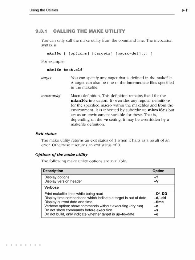
Using the Utilities 9-11
• • • • • • • •
9.3.1 CALLING THE MAKE UTILITY
You can only call the make utility from the command line. The invocation
syntax is
mkm16c [ [options] [targets] [macro=def]... ]
For example:
mkm16c test.elf
target You can specify any target that is defined in the makefile.
A target can also be one of the intermediate files specified
in the makefile.
macro=def Macro definition. This definition remains fixed for the
mkm16c invocation. It overrides any regular definitions
for the specified macro within the makefiles and from the
environment. It is inherited by subordinate mkm16c's but
act as an environment variable for these. That is,
depending on the -e setting, it may be overridden by a
makefile definition.
Exit status
The make utility returns an exit status of 1 when it halts as a result of an
error. Otherwise it returns an exit status of 0.
Options of the make utility
The following make utility options are available:
Description Option
Display options
Display version header
-?-V
Verbose
Print makefile lines while being read
Display time comparisons which indicate a target is out of date
Display current date and time
Verbose option: show commands without executing (dry run)
Do not show commands before execution
Do not build, only indicate whether target is up-to-date
-D/-DD-d/-dd-time-n-s-q

User's Manual9-12UTILITIES
OptionDescription
Input files
Use makefile instead of the standard makefile makefileChange to directory before reading the makefile
Read options from file
Do not read the mkm16c.mk file
-f makefile-G path-m file-r
Process
Always rebuild target without checking whether it is out-of-date
Run as a child process
Environment variables override macro definitions
Do not remove temporary files
On error, only stop rebuilding current target
Overrule the option -k (only stop rebuilding current target)
Make all target files precious
Touch the target files instead of rebuilding them
Treat target as if it has just been reconstructed
-a-c-e-K-k-S-p-t-W target
Error messages
Redirect error messages and verbose messages to a file
Ignore error codes returned by commands
Redirect messages to standard out instead of standard error
Show extended error messages
-err file-i-w-x
Table 9-3: Overview of make utility options
For a complete list and description of all make utility options, see section
4.5, Make Utility Options, in Chapter Tool Options of the Reference Manual.
9.3.2 WRITING A MAKEFILE
In addition to the standard makefile makefile, the make utility always
reads the makefile mkm16c.mk before other inputs. This system makefile
contains implicit rules and predefined macros that you can use in the
makefile makefile.
With the option -r (Do not read the mkm16c.mk file) you can prevent the
make utility from reading mkm16c.mk.
The default name of the makefile is makefile in the current directory. If
on a UNIX system this file is not found, the file Makefile is used as the
default. If you want to use other makefiles, use the option -f my_makefile.

Using the Utilities 9-13
• • • • • • • •
The makefile can contain a mixture of:
• targets and dependencies
• rules
• macro definitions or functions
• comment lines
• include lines
• export lines
To continue a line on the next line, terminate it with a backslash (\):
# this comment line is continued\
on the next line
If a line must end with a backslash, add an empty macro.
# this comment line ends with a backslash \$(EMPTY)
# this is a new line
Targets and dependencies
The basis of the makefile is a set of targets, dependencies and rules. A
target entry in the makefile has the following format:
target ... : [dependency ...] [; rule]
[rule]
...
Target lines must always start at the beginning of a line, leading white
spaces (tabs or spaces) are not allowed. A target line consists of one or
more targets, a semicolon and a set of files which are required to build the
target (dependencies). The target itself can be one or more filenames or
symbolic names.:
all: demo.elf final.elf
demo.elf final.elf: test.obj demo.obj final.obj
You can now can specify the target you want to build to the make utility.
The following three invocations all have the same effect:
mkm16c
mkm16c all
mkm16c demo.elf final.elf

User's Manual9-14UTILITIES
If you do not specify a target, the first target in the makefile (in this
example all) is build. The target all depends on demo.elf and
final.elf so the second and third invocation have also the same effect
and the files demo.elf and final.elf are built.
In MS-Windows you can normally use colons to denote drive letters. The
following works as intended: c:foo.obj : a:foo.c
If a target is defined in more than one target line, the dependencies are
added to form the target's complete dependency list:
all: demo.elf # These two lines are equivalent with:
all: final.elf # all: demo.elf final.elf
For target lines, macros and functions are expanded at the moment they
are read by the make utility. Normally macros are not expanded until the
moment they are actually used.
Special Targets
There are a number of special targets. Their names begin with a period.
.DEFAULT: If you call the make utility with a target that has no definition
in the make file, this target is build.
.DONE: When the make utility has finished building the specified
targets, it continues with the rules following this target.
.IGNORE: Non-zero error codes returned from commands are ignored.
Encountering this in a makefile is the same as specifying the
option -i on the command line.
.INIT: The rules following this target are executed before any other
targets are build.
.SILENT: Commands are not echoed before executing them.
Encountering this in a makefile is the same as specifying the
option -s on the command line.
.SUFFIXES: This target specifies a list of file extensions. Instead of
building a completely specified target, you now can build a
target that has a certain file extension. Implicit rules to build
files with a number of extensions are included in the system
makefile mkm16c.mk.

Using the Utilities 9-15
• • • • • • • •
If you specify this target with dependencies, these are added
to the existing .SUFFIXES target in mkm16c.mk. If you
specify this target without dependencies, the existing list is
cleared.
.PRECIOUS: Dependency files mentioned for this target are never
removed. Normally, if a command in a rule returns an error
or when the target construction is interrupted, the make
utility removes that target file. You can use the -p command
line option to make all target files precious.
Rules
A line with leading white space (tabs or spaces) is considered as a rule
and associated with the most recently preceding dependency line. A ruleis a line with commands that are executed to build the associated target.
A target-dependency line can be followed by one or more rules.
final.src : final.c # target and dependency
mv test.c final.c # rule1
cm16c final.c # rule2
You can precede a rule with one or more of the following characters:
@ does not echo the command line, except if -n is used.
- the make utility ignores the exit code of the command (ERRORLEVEL
in MS-DOS). Normally the make utility stops if a non-zero exit code is
returned. This is the same as specifying the option -i on the command
line or specifying the special .IGNORE target.
+ The make utility uses a shell or COMMAND.COM to execute the
command. If the '+' is not followed by a shell line, but the command is
a DOS command or if redirection is used (<, |, >), the shell line is
passed to COMMAND.COM anyway. For UNIX, redirection, backquote
(`) parentheses and variables force the use of a shell.
You can force mkm16c to execute multiple command lines in one
shell environment. This is accomplished with the token combination
';\'. For example:
cd c:\cm16c\bin ;\
ccm16c -V

User's Manual9-16UTILITIES
The ';' must always directly be followed by the '\' token. Whitespace is not
removed when it is at the end of the previous command line or when it is
in front of the next command line. The use of the ';' as an operator for a
command (like a semicolon ';' separated list with each item on one line)
and the '\' as a layout tool is not supported, unless they are separated with
whitespace.
The make utility can generate inline temporary files. If a line contains
<<LABEL (no whitespaces!) then all subsequent lines are placed in a
temporary file until the line LABEL is encountered. Next, <<LABEL is
replaced by the name of the temporary file.
Example:
lkm16c -o $@ -f <<EOF
$(separate "\n" $(match .obj $!))
$(separate "\n" $(match .a $!))
$(LKFLAGS)
EOF
The three lines between <<EOF and EOF are written to a temporary file
(for example mkce4c0a.tmp), and the rule is rewritten as lkm16c -o $@
-f mkce4c0a.tmp.
Instead of specifying a specific target, you can also define a general target.
A general target specifies the rules to generate a file with extension .ex1
to a file with extension .ex2. For example:
.SUFFIXES: .c
.c.src :
lkm16c $<
Read this as: to build a file with extension .src out of a file with
extension .c, call the compiler with $<. $< is a predefined macro that is
replaced with the basename of the specified file. The special target
.SUFFIXES: is followed by a list of file extensions of the files that are
required to build the target.
Implicit Rules
Implicit rules are stored in the system makefile mkm16c.mk and are
intimately tied to the .SUFFIXES special target. Each dependency that
follows the .SUFFIXES target, defines an extension to a filename which
must be used to build another file. The implicit rules then define how to
actually build one file from another. These files share a common
basename, but have different extensions.
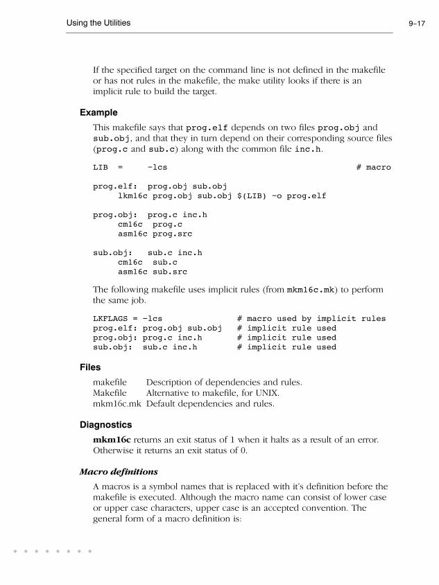
Using the Utilities 9-17
• • • • • • • •
If the specified target on the command line is not defined in the makefile
or has not rules in the makefile, the make utility looks if there is an
implicit rule to build the target.
Example
This makefile says that prog.elf depends on two files prog.obj and
sub.obj, and that they in turn depend on their corresponding source files
(prog.c and sub.c) along with the common file inc.h.
LIB = -lcs # macro
prog.elf: prog.obj sub.obj
lkm16c prog.obj sub.obj $(LIB) -o prog.elf
prog.obj: prog.c inc.h
cm16c prog.c
asm16c prog.src
sub.obj: sub.c inc.h
cm16c sub.c
asm16c sub.src
The following makefile uses implicit rules (from mkm16c.mk) to perform
the same job.
LKFLAGS = -lcs # macro used by implicit rules
prog.elf: prog.obj sub.obj # implicit rule used
prog.obj: prog.c inc.h # implicit rule used
sub.obj: sub.c inc.h # implicit rule used
Files
makefile Description of dependencies and rules.
Makefile Alternative to makefile, for UNIX.
mkm16c.mk Default dependencies and rules.
Diagnostics
mkm16c returns an exit status of 1 when it halts as a result of an error.
Otherwise it returns an exit status of 0.
Macro definitions
A macros is a symbol names that is replaced with it's definition before the
makefile is executed. Although the macro name can consist of lower case
or upper case characters, upper case is an accepted convention. The
general form of a macro definition is:

User's Manual9-18UTILITIES
MACRO = text and more text
Spaces around the equal sign are not significant. To use a macro, you must
access it's contents:
$(MACRO) # you can read this as
${MACRO} # the contents of macro MACRO
If the macro name is a single character, the parentheses are optional. Note
that the expansion is done recursively, so the body of a macro may
contain other macros. These macros are expanded when the macro is
actually used, not at the point of definition:
FOOD = $(EAT) and $(DRINK)
EAT = meat and/or vegetables
DRINK = water
export FOOD
The macro FOOD is expanded as meat and/or vegetables and
water at the moment it is used in the export line.
Predefined Macros
MAKE Holds the value mkm16c. Any line which uses MAKE,
temporarily overrides the option -n (Show commands
without executing), just for the duration of the one line. This
way you can test nested calls to MAKE with the option -n.
MAKEFLAGS
Holds the set of options provided to mkm16c (except for
the options -f and -d). If this macro is exported to set the
environment variable MAKEFLAGS, the set of options is
processed before any command line options. You can pass
this macro explicitly to nested mkm16c's, but it is also
available to these invocations as an environment variable.
PRODDIR Holds the name of the directory where mkm16c is installed.
You can use this macro to refer to files belonging to the
product, for example a library source file.
DOPRINT = $(PRODDIR)/lib/src/_doprint.c
When mkm16c is installed in the directory /cm16c/bin this
line expands to:
DOPRINT = /cm16c/lib/src/_doprint.c

Using the Utilities 9-19
• • • • • • • •
SHELLCMD Holds the default list of commands which are local to the
SHELL. If a rule is an invocation of one of these commands, a
SHELL is automatically spawned to handle it.
TMP_CCPROG
Holds the name of the control program: ccm16c. If this
macro and the TMP_CCOPT macro are set and the command
line argument list for the control program exceeds 127
characters, then mkm16c creates a temporary file with the
command line arguments. mkm16c calls the control program
with the temporary file as command input file.
TMP_CCOPT
Holds -f, the control program option that tells it to read
options from a file. (This macro is only available for the
Windows command prompt version of mkm16c.)
$ This macro translates to a dollar sign. Thus you can use "$$"
in the makefile to represent a single "$".
There are several dynamically maintained macros that are useful as
abbreviations within rules. It is best not to define them explicitly.
$* The basename of the current target.
$< The name of the current dependency file.
$@ The name of the current target.
$? The names of dependents which are younger than the target.
$! The names of all dependents.
The $< and $* macros are normally used for implicit rules. They may be
unreliable when used within explicit target command lines. All macros
may be suffixed with F to specify the Filename components (e.g. ${*F},
${@F}). Likewise, the macros $*, $< and $@ may be suffixed by D to
specify the directory component.
The result of the $* macro is always without double quotes ("), regardless
of the original target having double quotes (") around it or not.
The result of using the suffix F (Filename component) or D (Directory
component) is also always without double quotes ("), regardless of the
original contents having double quotes (") around it or not.

User's Manual9-20UTILITIES
Functions
A function not only expands but also performs a certain operation.
Functions syntactically look like macros but have embedded spaces in the
macro name, e.g. '$(match arg1 arg2 arg3 )'. All functions are built-in and
currently there are five of them: match, separate, protect, exist and
nexist.
match The match function yields all arguments which match a
certain suffix:
$(match .obj prog.obj sub.obj mylib.a)
yields:
prog.obj sub.obj
separate The separate function concatenates its arguments using the
first argument as the separator. If the first argument is
enclosed in double quotes then '\n' is interpreted as a
newline character, '\t' is interpreted as a tab, '\ooo' is
interpreted as an octal value (where, ooo is one to three octal
digits), and spaces are taken literally. For example:
$(separate "\n" prog.obj sub.obj)
results in:
prog.obj
sub.obj
Function arguments may be macros or functions themselves.
So,
$(separate "\n" $(match .obj $!))
yields all object files the current target depends on, separated
by a newline string.
protect The protect function adds one level of quoting. This
function has one argument which can contain white space. If
the argument contains any white space, single quotes, double
quotes, or backslashes, it is enclosed in double quotes. In
addition, any double quote or backslash is escaped with a
backslash.

Using the Utilities 9-21
• • • • • • • •
Example:
echo $(protect I'll show you the "protect"
function)
yields:
echo "I'll show you the \"protect\"
function"
exist The exist function expands to its second argument if the
first argument is an existing file or directory.
Example:
$(exist test.c ccm16c test.c)
When the file test.c exists, it yields:
ccm16c test.c
When the file test.c does not exist nothing is expanded.
nexist The nexist function is the opposite of the exist function. It
expands to its second argument if the first argument is not an
existing file or directory.
Example:
$(nexist test.src ccm16c test.c)
Conditional Processing
Lines containing ifdef, ifndef, else or endif are used for conditional
processing of the makefile. They are used in the following way:
ifdef macro-nameif-lineselse
else-linesendif
The if-lines and else-lines may contain any number of lines or text of any
kind, even other ifdef, ifndef, else and endif lines, or no lines at all.
The else line may be omitted, along with the else-lines following it.
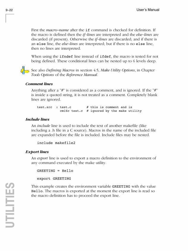
User's Manual9-22UTILITIES
First the macro-name after the if command is checked for definition. If
the macro is defined then the if-lines are interpreted and the else-lines are
discarded (if present). Otherwise the if-lines are discarded; and if there is
an else line, the else-lines are interpreted; but if there is no else line,
then no lines are interpreted.
When using the ifndef line instead of ifdef, the macro is tested for not
being defined. These conditional lines can be nested up to 6 levels deep.
See also Defining Macros in section 4.5, Make Utility Options, in Chapter
Tools Options of the Reference Manual.
Comment lines
Anything after a "#" is considered as a comment, and is ignored. If the "#"
is inside a quoted string, it is not treated as a comment. Completely blank
lines are ignored.
test.src : test.c # this is comment and is
cm16c test.c # ignored by the make utility
Include lines
An include line is used to include the text of another makefile (like
including a .h file in a C source). Macros in the name of the included file
are expanded before the file is included. Include files may be nested.
include makefile2
Export lines
An export line is used to export a macro definition to the environment of
any command executed by the make utility.
GREETING = Hello
export GREETING
This example creates the environment variable GREETING with the value
Hello. The macros is exported at the moment the export line is read so
the macro definition has to proceed the export line.

Using the Utilities 9-23
• • • • • • • •
9.4 ARCHIVER
The archiver arm16c is a program to build and maintain your own library
files. A library file is a file with extension .a and contains one or more
object files (.obj) that may be used by the linker.
The archiver has five main functionalities:
• Deleting an object module from the library
• Moving an object module to another position in the library file
• Replacing an object module in the library or add a new object module
• Showing a table of contents of the library file
• Extracting an object module from the library
The archiver takes the following files for input and output:
assembler
relocatable object file
linker
asm16c
lkm16c
relocatable object library
.a
archiver
arm16c .obj
Figure 9-1: ELF/DWARF archiver and library maintainer
The linker optionally includes object modules from a library if that module
resolves an external symbol definition in one of the modules that are read
before.
9.4.1 CALLING THE ARCHIVER
You can only call the archiver from the command line. The invocation
syntax is:
arm16c key_option [sub_option...] library [object_file]
key_option With a key option you specify the main task which the
archiver should perform. You must always specify a key
option.

User's Manual9-24UTILITIES
sub_option Sub-options specify into more detail how the archiver should
perform the task that is specified with the key option. It is
not obligatory to specify sub-options.
library The name of the library file on which the archiver performs
the specified action. You must always specify a library name,
except for the option -? and -V. When the library is not in
the current directory, specify the complete path (either
absolute or relative) to the library.
object_file The name of an object file. You must always specify an
object file name when you add, extract, replace or remove an
object file from the library.
Options of the archiver utility
The following archiver options are available:
Description Option Sub-option
Main functions (key options)
Replace or add an object module -r -a -b -c -u -v
Extract an object module from the library -x -v
Delete object module from library -d -v
Move object module to another position -m -a -b -v
Print a table of contents of the library -t -s0 -s1
Print object module to standard output -p
Sub-options
Append or move new modules after existing
module name-a name
Append or move new modules before
existing module name-b name
Create library without notification if library
does not exist
-c
Preserve last-modified date from the library -o
Print symbols in library modules -s{0|1}
Replace only newer modules -u
Verbose -v

Using the Utilities 9-25
• • • • • • • •
Sub-optionOptionDescription
Miscellaneous
Display options -?
Display version header -V
Read options from file -f file
Suppress warnings above level n -wn
Table 9-4: Overview of archiver options and sub-options
For a complete list and description of all archiver options, see section 4.6,
Archiver Options, in Chapter Tool Options of the Reference Manual.
9.4.2 EXAMPLES
Create a new library
If you add modules to a library that does not yet exist, the library is
created. To create a new library with the name mylib.a and add the
object modules cstart.obj and calc.obj to it:
arm16c -r mylib.a cstart.obj calc.obj
Add a new module to an existing library
If you add a new module to an existing library, the module is added at the
end of the module. (If the module already exists in the library, it is
replaced.)
arm16c -r mylib.a mod3.obj
Print a list of object modules in the library
To inspect the contents of the library:
arm16c -t mylib.a
The library has the following contents:
cstart.obj
calc.obj
mod3.obj

User's Manual9-26UTILITIES
Move an object module to another position
To move mod3.obj to the beginning of the library, position it just before
cstart.obj:
arm16c -mb cstart.obj mylib.a mod3.obj
Delete an object module from the library
To delete the object module cstart.obj from the library mylib.a:
arm16c -d mylib.a cstart.obj
Extract all modules from the library
Extract all modules from the library mylib.a:
arm16c -x mylib.a

Using the Utilities 9-27
• • • • • • • •
9.5 FLASH UTILITY
With the flash utility flashm16c you can load an ELF, Intel Hex or
Motorola S-record file in a flash device.
Configure flash settings from EDE
You can configure all flash settings from EDE.
1. From the Project menu, select Project Options...
The Project Options dialog appears.
2. Expand the Flasher entry and select Flasher Settings.
3. Select serial or USB communication.
4. Select the flash actions.
You can perform several actions with the flash tool:
Blank check
Select this to check if the flash device is properly erased.
Full erase
Select this to erase the entire flash memory.
Program
Select this to program the flash device with the specified file.
Verify
Select this to compare a Motorola S-record file (or other absolute file) with
the content of the FLASH.
9.5.1 CALLING THE FLASH UTILITY
You can call the flash utitlity from the command line or from EDE. The
invocation syntax is:
flashm16c [option]... [file]...
If you invoke flashm16c with the -nodialog command line option the
absolute file is directly flashed into the target.

User's Manual9-28UTILITIES
From EDE, you can start flashing with one click on the Flash an ELF,
Intel Hex or Motorola S-Rec file button located in the toolbar.
Options of the flash utility
The following flash utility options are available:
Description Option
Target selection
Default: M16C20 - M16C60 no option
M16C10 -M16C10
R8C10 - R8C13 -R8C10
Flasher settings
Flash actions:
B - Blank check
F - Erase all blocks
P - Program file
V - Verify programmed blocks
-actions=flag...
Flash ID code
Use id to access the flash -id=id
When IDs 00 or FF fail, do not retry with
opposite
-noidretry
Communication settings
Specify baud rate (default: 9600) -baudrate=baudrate
Specify the serial port to use -com{1|2|3|4}
Use USB connection -USB
Set the target board and upload the hex
file to the USB monitor board
-set_USB_target=target
Files
Set working directory -dir dir
Read options from file -f file
Save original contents before overwriting -backup file
Specify start/end address for backup
(default: 0xC0000 - 0xFFFFF)
-backup_range=start, end

Using the Utilities 9-29
• • • • • • • •
OptionDescription
Append errors to file -err file
Miscellaneous
Do not use the Flash dialog -nodialog
Log level (detail of warnings, 0=none,
3=all)
-level={0|1|2|3}
Display short description of options -h
Show on-board flash program version -version
Example
To erase the flash device and flash the file demo.s at a baud rate of 38400
in a device connected at serial port COM2, using a command line
interface, type:
flashm16c -actions=FP -baudrate=38400 -com2
-id=00.00.00.00.00.00.00 -nodialog demo.s

User's Manual9-30UTILITIES

INDEXINDEX

IndexIndex-2INDEX
INDEX
Index Index-3
• • • • • • • •
Symbols-M option, 3-19
__asm, syntax, 3-20
__asmfunc, 3-37
__atbit(), 3-7
__bita, 3-13
__BUILD__, 3-29
__far, 3-13
__LITTLE_ENDIAN__, 3-29
__MODEL__, 3-29
__near, 3-13
__paged, 3-13
__REVISION__, 3-29
__rom, 3-13
__sfr, 3-13, 3-16
__VERSION__, 3-29
Aabsolute address, 3-18
absolute variable, 3-18
addressing modes, 4-6
architecture definition, 8-21
archiver, 9-23
invocation, 9-23options (overview), 9-24
arm16c, 9-23
assembler, setting options, 7-6
assembler controls, overview, 4-16
assembler directives, overview, 4-14
assembler error messages, 7-9
assembler options, overview, 7-6
assembly, programming in C, 3-20
assembly expressions, 4-7
assembly functions, 3-37
assembly syntax, 4-3
auto_switch, 3-31
Bbackend
compiler phase, 5-5optimization, 5-5
board specification, 8-22
bounds checking, 5-21
build, viewing results, 2-17
bus definition, 8-22
Cccall to jump optimization, 5-9
ccm16c, 9-4
CCM16COPT, 9-8
character, 4-4
clock(), 6-8
coalescer, 5-8, 5-9
code checking, 5-16
code generator, 5-5
Code instrumentation, 6-5
common subexpression elimination,
5-7
compaction, 5-7
compile, 2-17
compile time error checking, 5-19
compiler
invocation, 5-10optimizations, 5-5setting options, 5-11
compiler error messages, 5-19
compiler options, overview, 5-11, 5-12
compiler phases
backend, 5-4code generator phase, 5-5optimization phase, 5-5peephole optimizer phase, 5-5

IndexIndex-4INDEX
frontend, 5-4optimization phase, 5-4parser phase, 5-4preprocessor phase, 5-4scanner phase, 5-4
conditional assembly, 4-26
conditional jump reversal, 5-8
configuration
EDE directories, 1-7UNIX, 1-9
constant propagation, 5-7
continuation, 4-18
control flow simplification, 5-7
control program, 9-4
invocation, 9-4options (overview), 9-5
control program options, overview,
9-5, 9-24
controls, 4-4
copy table, compression, 8-10
creating a makefile, 2-13
CSE, 5-7
Ddata types, 3-10
bit, 3-12dead code elimination, 5-8
delete duplicate code sections, 8-10
delete duplicate constant data, 8-10
delete unreferenced sections, 8-10
derivative definition, 8-21
directive, conditional assembly, 4-26
directives, 4-4
directories, setting, 1-7, 1-9
division by zero, 5-23
EEDE, 2-3
build an application, 2-17
create a project, 2-11create a project space, 2-10rebuild an application, 2-18specify development tool options,
2-14starting, 2-8
ELF/DWARF, archiver, 9-23
ELF/DWARF2 format, 8-8
Embedded Development Environment,
2-3
environment variables, 1-9
ASM16CINC, 1-9CCM16CBIN, 1-9CCM16COPT, 1-9, 9-8CM16CINC, 1-9LIBM16C, 1-9LIBR8C, 1-9LM_LICENSE_FILE, 1-10, 1-16PATH, 1-9TASKING_LIC_WAIT, 1-10TMPDIR, 1-10
diagnostics, compiler, 5-19
error messages
assembler, 7-9compiler, 5-19linker, 8-38
expression simplification, 5-7
expressions, 4-7
absolute, 4-7relative, 4-7relocatable, 4-7
Ffile extensions, 2-6
first fit decreasing, 8-9
flash utility, 9-27
invocation, 9-27options (overview), 9-28
flashm16c, 9-27
floating license, 1-12
flow simplification, 5-7

Index Index-5
• • • • • • • •
formatters
printf, 3-45scanf, 3-45
forward store, 5-8
frontend
compiler phase, 5-4optimization, 5-4
function, 4-11
syntax, 4-11function qualifiers
__asmfunc, 3-37__bankswitch, 3-40__frame, 3-41__interrupt, 3-39__interrupt_fixed, 3-39
functions, 3-32
inline, 3-34parameter passing, 3-32return types, 3-33
Hhost ID, determining, 1-17
host name, determining, 1-17
IIEEE 32-bit single precision format,
3-11
IEEE 64-bit double precision format,
3-11
include files
default directory, 5-15, 7-8, 8-17setting search directories, 1-7, 1-9
incremental linking, 8-18
initialized variables, 3-30
inline assembly, 3-25
__asm, 3-20inline functions, 3-34
inlining functions, 5-7
input specification, 4-3
installation
licensing, 1-12Linux, 1-4
Debian, 1-5RPM, 1-4tar.gz, 1-5
UNIX, 1-6Windows 95/98/XP/NT/2000, 1-3
instructions, 4-4
Intel-Hex format, 8-8
interprocedural register optimization,
5-8
interrupt frame, 3-41
interrupt function, 3-38
interrupt service routine, 3-38
defining, 3-39intrinsic functions, 3-36
Jjump chain, 3-31
jump chaining, 5-8
jump table, 3-31
jump_switch, 3-31
Llabels, 4-3, 4-6
libraries
rebuilding, 3-46setting search directories, 1-8, 1-9
library, user, 8-14
library maintainer, 9-23
license
floating, 1-12node-locked, 1-12obtaining, 1-12wait for available license, 1-10
license file
location, 1-16setting search directory, 1-10

IndexIndex-6INDEX
licensing, 1-12
linear_switch, 3-31
linker, optimizations, 8-9
linker error messages, 8-38
linker options, overview, 8-12
linker output formats
ELF/DWARF2 format, 8-8Intel-Hex format, 8-8Motorola S-record format, 8-8
linker script file, 8-8
architecture definition, 8-21board specification, 8-22bus definition, 8-22derivative definition, 8-21memory definition, 8-22processor definition, 8-22section layout definition, 8-23
linker script language (LSL), 8-8, 8-19
internal memory, 8-26on-chip memory, 8-26
linking process, 8-4
linking, 8-6locating, 8-7optimizing, 8-9
list file, generating, 7-8
LM_LICENSE_FILE, 1-16
local label override, 4-25
lookup table, 3-31
lookup_switch, 3-31
loop transformations, 5-8
lsl, 8-19
Mmacro, 4-4
argument concatenation, 4-22argument operator, 4-22argument string, 4-24call, 4-21conditional assembly, 4-26definition, 4-19
dup directive, 4-26local label override, 4-25return decimal value operator, 4-23return hex value operator, 4-23
macro argument string, 4-24
macro operations, 4-19
macros, 4-19
macros in C, 3-28
make utility, 9-9
.DEFAULT target, 9-14
.DONE target, 9-14
.IGNORE target, 9-14
.INIT target, 9-14
.PRECIOUS target, 9-15
.SILENT target, 9-14
.SUFFIXES target, 9-14conditional processing, 9-21dependency, 9-13else, 9-21endif, 9-21exist function, 9-21export line, 9-22functions, 9-20ifdef, 9-21ifndef, 9-21implicit rules, 9-16invocation, 9-11macro definition, 9-11macro MAKE, 9-18macro MAKEFLAGS, 9-18macro PRODDIR, 9-18macro SHELLCMD, 9-19macro TMP_CCOPT, 9-19macro TMP_CCPROG, 9-19makefile, 9-9, 9-12match function, 9-20nexist function, 9-21options (overview), 9-11predefined macros, 9-18protect function, 9-20rules in makefile, 9-15separate function, 9-20

Index Index-7
• • • • • • • •
special targets, 9-14make utility options, overview, 9-11
makefile, 9-9
automatic creation of, 2-13updating, 2-13writing, 9-12
malloc checks, 5-22
memory definition, 8-22
memory models, 3-19
large, 3-19medium, 3-19small, 3-19
memory qualifiers, 3-12
__bita, 3-13__far, 3-13__near, 3-13__paged, 3-13__rom, 3-13, 3-30__sfr, 3-13
memory type qualifiers, 3-13
MISRA-C, 5-16
advisory rules, 5-17required rules, 5-17
mkm16c. See make utility
Motorola S-record format, 8-8
Nnode-locked license, 1-12
Ooperands, 4-5
opimizations, size/speed trade-off, 5-9
optimization (backend)
call to jump, 5-9coalescer, 5-8, 5-9interprocedural register optimization,
5-8loop transformations, 5-8peephole optimizations, 5-9
subscript strength reduction, 5-8optimization
backend, 5-5compiler, common subexpression
elimination, 5-7frontend, 5-4
optimization (frontend)
compaction, 5-7conditional jump reversal, 5-8constant propagation, 5-7control flow simplification, 5-7dead code elimination, 5-8expression simplification, 5-7flow simplification, 5-7forward store, 5-8inlining functions, 5-7jump chaining, 5-8reverse inlining, 5-7switch optimization, 5-7
optimizations
compiler, 5-5compress ROM image, 8-10copy table compression, 8-10delete duplicate code sections, 8-10delete duplicate constant data, 8-10delete unreferenced sections, 8-10first fit decreasing, 8-9
Pparameter passing, 3-32
parser, 5-4
peephole optimization, 5-5, 5-9
pragmas, 3-27
inline, 3-35noinline, 3-35smartinline, 3-35
predefined macros in C, 3-28
__CM16C__, 3-29__CPU__, 3-29__DSPC__, 3-29__M16C__, 3-29

IndexIndex-8INDEX
__R8C__, 3-29__SINGLE_FP__, 3-29__TASKING__, 3-29
printf formatter, 3-45
processor, selecting a core, 5-10, 7-5
processor definition, 8-22
Profiling, 6-3
call graph incorrect, 6-14code instrumentation, 6-5heap too small, 5-25, 6-10with debugger, 6-4with simulator, 6-4
project, 2-7
add new files, 2-12create, 2-11
project file, 2-7
project space, 2-7
create, 2-10project space file, 2-7
Qquality assurence report, 5-17
Rrebuilding libraries, 3-46
register allocator, 5-5
register bank switching, 3-40
register usage, 3-32, 3-33
registers, 4-5, 4-6
relocatable object file, 8-3
debug information, 8-6header information, 8-6object code, 8-6relocation information, 8-6symbols, 8-6
relocation expressions, 8-7
reserved symbols, 4-6
return decimal value operator, 4-23
return hex value operator, 4-23
reverse inlining, 5-7
rom, 3-13
ROM image, compression, 8-10
ROM monitor, 2-16
run-time error checking, 5-21
division by zero, 5-23malloc checks, 5-22bounds checking, 5-21, 5-23unhandled case switch, 5-22
Sscanf formatter, 3-45
scanner, 5-4
section layout definition, 8-23
section names, 3-42
sections, 3-42, 4-17
absolute, 4-18activation, 4-18cleared, 4-19definition, 4-17
software installation
Linux, 1-4UNIX, 1-6Windows 95/98/XP/NT/2000, 1-3
special function registers, define, 3-16
stack overflow, 5-23
statement, 4-3
storage types. See memory qualifiers
string, 3-30
substring, 4-8subscript strength reduction, 5-8
substring, 4-8
switch, restore, 3-31
switch optimization, 5-7
switch statement, 3-31
symbol, 4-6
synchronize options with ROM
monitor, 2-16
syntax of an expression, 4-7

Index Index-9
• • • • • • • •
Ttemporary files, setting directory, 1-10
transferring parameters between
functions, 3-32
Uunhandled case switch, 5-22
updating makefile, 2-13
utilities
archiver, 9-23
arm16c, 9-23ccm16c, 9-4control program, 9-4flash utility, 9-27flashm16c, 9-27make utility, 9-9mkm16c, 9-9
Vvariables, initialized, 3-30
verbose option, linker, 8-17

IndexIndex-10INDEX

![Finishing Up Instruction Formats & CALL (Compiler/Assembler/Linker/Loader)cs61c/sp18/lec/08/lec08.pdf · 2018-02-08 · Compiler Assembler Machine Interpretation temp = v[k]; v[k]](https://img.pdfslide.us/doc/110x75/5f259a470ae6e45aab61ce85/finishing-up-instruction-formats-call-compilerassemblerlinkerloader-cs61csp18lec08lec08pdf.jpg)