Embed Size (px)
Citation preview

NORMAL
MWO effective date 1 August 1987 and completion date 30 September 1991
MWO 9-2320-218-34
DEPARTMENT OF THE ARMY MODIFICATION WORK ORDER
INSTALLATION OF
ROLLOVER PROTECTION SYSTEM(1/4-TON VEHICLE M151A2)
HEADQUARTERS, DEPARTMENT OF THE ARMY, WASHINGTON, D.C.1 AUGUST 1987
REPORTING OF ERRORS AND RECOMMENDING IMPROVEMENTS
You can help improve this manual. If you find any mistakes or if you know of a way toimprove the procedures, please let us know. Mail your letter, DA Form 2028(Recommended Changes to Publications and Blank Forms), or DA Form 2028-2 located inthe back of this manual direct to: Commander, U.S. Army Tank-Automotive Command,Attn: AMSTA-MB, Warren, MI 48397-5000. A reply will be furnished to you.

MWO 9-2320-218-34
1. PURPOSE OF MODIFICATION.
The purpose of this modification is to provide vehicle with a roll bar and occupant restraint system to minimize occupantinjury during vehicle rollover and collision.
2. VEHICLE INSPECTION.
a. Vehicles to be modified will be at 10/20 standards and will meet the minimum criteria for installation of theROPS. No body or frame repair is authorized by the installation team at the time of MWO 9-2320-218-34 applications.
b. Vehicles will be inspected for any condition that may prevent the proper installation of the RolloverProtection System (ROPS) in accordance with this MWO such as:
(1) Rust/Corrosion/Damage (illustrated below): Probe the underside of the entire vehicle with apunch 3/8" diameter flat point, NSN 5720-00-273-0001 and a hammer inserted NSN 5120-00-903-8553 with the mediumplastic face NSN 5120-00-585-8202 installed or a 24 ounce rubber mallet NSN 5120-00-293-3399. To identify non-repairable metal, strike suspected metal surface every ten inches with the punch and mallet. Good metal will remainintact or dent slightly, corroded areas will punch through or crumble. Pay particular attention to those high load structuralframe members in and around the rear differential and suspension mounts for cracks or damage.
(2) Kits, Modifications, Repairs, or Other Damage: Inspect entire vehicle for any kit, modification,repair, or other damage located in those areas illustrated on page 2. For example, kits other than those addressed by theMWO, welded or bolted reinforcement plates, body parts and brackets, holes, body filler materials, damage or anycondition that may cause interference during the installation of the MWO. Inspection may require the use of probes,hammers/mallets, punches, or any other common tools as determined necessary.
c. Any vehicle condition, identified during this inspection, that will prevent the proper installation of ROPS,as specified by this MWO, is justification for denial of application. Vehicles failing this inspection and identified as nonerepairable will be identified with the following statement on DA Form 2407 "Unsafe for Operation" - "Vehicle to beDeadlined". At the discretion of the installation team, those vehicles determined to be acceptable after repair will beidentified as such, and returned to the unit for repair.
d. Required Criteria.
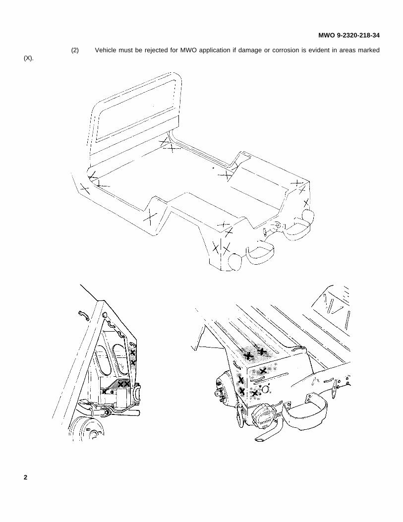
(1) Vehicle must be rejected for MWO application if any condition described in paragraph b is evidentin areas marked (X).
1
MWO 9-2320-218-34
(2) Vehicle must be rejected for MWO application if damage or corrosion is evident in areas marked(X).
2

MWO 9-2320-218-34
3. PRIORITY CLASSIFICATION.
This modification is classified as normal.a. VEHICLES IN USE (including vehicles in supply or maintenance activities below depot level and vehicles
in administrative storage): Vehicles in use will be modified as soon as feasible, but no later than the scheduled completiondate.
b. Vehicles not modified after expiration MWO completion date will be reported as NORM/NOT READY inaccordance with applicable Army regulations.
4. END ITEM OR SYSTEM TO BE MODIFIED.
a. TRUCK, UTILITY: 1/4-ton, 4x4, M151A2 (2320-00-177-9258)SERIAL NO. RANGE: All
b. Vehicle National Stock Number (NSN) will be changed to 2320-01-264-4819 as indicated on new dataplate supplied with the MWO.
5. MODULES (COMPONENTS, ASSEMBLIES, SUBASSEMBLIES, BOARDS, AND CARDS) TO BE MODIFIED.
HARD TOP KIT INSTALLEDNOMENCLATURE NSN PART NO.
Door Hard Top, Right 2510-00-470-1569 7345392Door Hard Top, Left 2510-00-177-7777 7345391
6. PART(S) TO BE MODIFIED.
DEEP WATER FORDING KIT INSTALLEDNOMENCLATURE NSN PART NO. PARA. NO.
Support, Exhaust Pipe N/A 11660430 11.b.
7. APPLICATION.
a. TIME COMPLIANCE SCHEDULE. MWO effective date 1 August 1987 and completion date30 September 1991.
b. LEVEL OF MAINTENANCE. Intermediate forward (Direct Support).c. APPLIED BY. Two persons with the following specialty are required to install MWO kits: wheeled vehicle
repairman (MOS-63W) or equivalent civilian mechanic.d. TIME REQUIRED (time for completion of MWO application to one end item).
(1) Total of 40.0 man-hours using 2 men.(2) Total of 20.0 hours downtime for one end item.
e. ADDITIONAL INFORMATION.(1) Refer to MWO fielding plan.(2) Approval authority for alterations/modifications to equipment, or any deviation from the
procedures specified by this publication will be coordinated through the Depot Maintenance Division Product ImprovementManagement Branch (AMSTA-MRP), U.S. Army Tank-Automotive Command (TACOM), Warren, MI 48397-5000.
3

MWO 9-2320-218-34
8. TECHNICAL PUBLICATIONS AFFECTED/CHANGED AS A RESULT OF THIS MWO.• TB 9-2320-218-10-1 • TM 9-2320-218-34-1• TM 9-2320-218-10 • TM 9-2320-218-34P• TM 9-2320-218-20-1-1 • LO 9-2320-218-12• TM 9-2320-218-20-1-2 • TM 9-2320-218-10 HR• TM 9-2320-218-20P
9. SUPPLY KITS, PARTS, AND DISPOSITION.
a. KIT/PARTS REQUIRED TO ACCOMPLISH MWO.
(1) KITS. The following kit is required to accomplish this modification and must be checked forcompleteness before starting the job.
MODIFICATION KIT 12301498ITEM NAME PART NO. QTY. FIGURE AND
ITEM NO.
Reflector 11663067-1 1 2-9Anchor 12301256 2 2-3
Bracket 12301273 2 2-8Tape, Pressure Sensitive 12302504 1 2-1()
Rollbar, Front, L.H. 12356641-1 1 1-4
Rollbar, Front, R.H. 12356641-2 1 1-1Rollbar, Intermediate, R.H. 12356642 1 1-2
Rollbar, Rear, R.H. 12356643 1 1-3
Crossbar, Front 12356644-1 2 1-8Crossbar, Rear 12356644-2 2 1-7
Bracket, Rollbar Front, R.H. 12356647-1 1 1-14
Bracket, Rollbar Front, L.H. 12356647-2 1 1-11Bracket, Rollbar Intermediate, L.H. 12356648-I 1 1-10
Bracket, Rollbar Intermediate, R.H. 12356648-2 1 1-13
Bracket, Rollbar Rear, L.H. 12356649-1 1 1-12Bracket, Rollbar Rear, R.H. 12356649-2 1 1-9
Reinforcement, Light Switch 12356F650 2 3-5
Reinforcement, Trailer Socket 12356651 1 3-2Handle, Door, L.H. 12356652-1 1 3-10
Handle, Door, R.H. 12356652-2 1 3-10
Rollbar, Intermediate, L.H. 12356653 1 1-5Rollbar, Rear, L.H. 12356654 1 1-6
Clamp, Rollbar to Air Intake 12356658 1 3-13
4

MWO 9-2320-218-34
Brace, Rollbar to Air Intake 12356659 1 3-14Bracket, Seat Belt Anchor 12356660 2 2-4
Bracket, Seat Belt, Rear 12356663 1 3-6
Belt Assembly, Front 12356667 2 2-1Belt Assembly, Rear 12356668 2 2-7
Padding, Impact 12356670 4 4-5
Restraint, Front, R.H. 12356671-1 1 4-1Restraint, Front, L.H. 12356671-2 1 4-1
Restraint, Rear, L.H. 12356672-1 1 4-4
Restraint, Rear, R.H. 12356672-2 1 4-4Plate, Data 12356673 1 3-4
Label 12356763 1 2-12
Bracket, Retractor R.H. 12368351 1 2-13Bracket, Retractor L.H. 12368352 1 2-13
Bracket 12368353 2 1-15
Plate, Data 12368354 1 3-23Nut, 1/4-28 UTNJF-38 MS21042-4 1 3-7
Nut, .1900-32 UNJF-38 MS21044-N3 6 3-7
Nut, 5/16-24 UNJF-38 MS21044-N5 2 3-16Cotter Pin MS24665-287 2 3-11
Washer, 11/32 Inside Dia. MS27183-12 2 3-17
Washer, 15/32 Inside Dia. MS27183-16 6 2-11Washer, 17/32 Inside Dia. MS27183-18 12 3-8/2-5/4-3
Screw, 1/4-20 UNC-2A, 3/4 in. long MS35206-281 1 3-3
Screw, #10-32 UNF-2A, 5/8 in. long MS35207-264 6 3-20Washer, Lock, #10 Internal Tooth MS35333-39 12 3-19
Washer, Lock, 5/16 Internal Tooth MS35333-41 3 3-19
Washer, Lock, 1/2 Internal Tooth MS35333-44 5 3-19Washer, Lock, 1/4 Internal Tooth MS35334-19 4 3-19
Washer, Lock, 1/4 External Tooth MS35335-33 11 3-19
Washer, Lock, #8 Hel, Spring MS35338-42 1 3-19Washer, Lock, 5/16 Hel, Spring MS35338-45 14 3-19
Washer, Lock, 1/2 Hel, Spring MS35338-48 2 3-12
5
MWO 9-2320-218-34
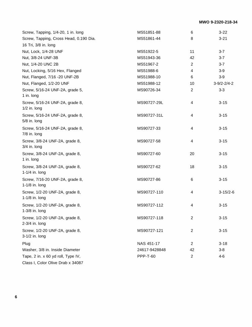
Screw, Tapping, 1/4-20, 1 in. long MS51851-88 6 3-22Screw, Tapping, Cross Head, 0.190 Dia. MS51861-44 8 3-21
16 Tri, 3/8 in. long
Nut, Lock, 1/4-28 UNF MS51922-5 11 3-7Nut, 3/8-24 UNF-3B MS51943-36 42 3-7
Nut, 1/4-20 UNC 2B MS51967-2 2 3-7
Nut, Locking, 5/16 Hex, Flanged MS51988-6 4 3-9Nut, Flanged, 7/16 -20 UNF-2B MS51988-10 6 3-9
Nut, Flanged, 1/2-20 UNF MS51988-12 10 3-9/2-2/4-2
Screw, 5/16-24 UNF-2A, grade 5, MS90726-34 2 3-31 in. long
Screw, 5/16-24 UNF-2A, grade 8, MS90727-29L 4 3-151/2 in. long
Screw, 5/16-24 UNF-2A, grade 8, MS90727-31L 4 3-155/8 in. long
Screw, 5/16-24 UNF-2A, grade 8, MS90727-33 4 3-157/8 in. long
Screw, 3/8-24 UNF-2A, grade 8, MS90727-58 4 3-153/4 in. long
Screw, 3/8-24 UNF-2A, grade 8, MS90727-60 20 3-151 in. long
Screw, 3/8-24 UNF-2A, grade 8, MS90727-62 18 3-151-1/4 in. long
Screw, 7/16-20 UNF-2A, grade 8, MS90727-86 6 3-151-1/8 in. long
Screw, 1/2-20 UNF-2A, grade 8, MS90727-110 4 3-15/2-61-1/8 in. long
Screw, 1/2-20 UNF-2A, grade 8, MS90727-112 4 3-151-3/8 in. long
Screw, 1/2-20 UNF-2A, grade 8, MS90727-118 2 3-152-3/4 in. long
Screw, 1/2-20 UNF-2A, grade 8, MS90727-121 2 3-153-1/2 in. long
Plug NAS 451-17 2 3-18Washer, 3/8 in. Inside Diameter 24617-9428848 42 3-8
Tape, 2 in. x 60 yd roll, Type IV, PPP-T-60 2 4-6
Class I, Color Olive Drab x 34087
6

MWO 9-2320-218-34
Figure 1. Modification Kit 12301498.
7

MWO 9-2320-218-34
Figure 2. Modification Kit 12301498.
8

MWO 9-2320-218-34
Figure 3. Modification Kit 12301498.
9

MWO 9-2320-218-34
Figure 4. Modification Kit 12301498.
10

MWO 9-2320-218-34
(2) PARTS. The following parts are required to complete this modification for vehicles equipped withdeepwater fording kit, and must be requisitioned from supply.
QUANTITY REQUIREDNSN ITEM NAME AND PART NUMBER PER END ITEM
Washer, Lock, 1/4 Dia. MS35335-33 10Internal ToothWasher, Lock, 5/16 Dia. MS35338-45 1Nut, Lock, 3/8-24 UNF-2B MS51922-21 2Nut, Lock, 5/16-18 UNC MS51988-5 17Gasket 7331368 1
b. KITS. The modification kit 12301498 weighs 347 lbs., measures 5 ft. x 3.33 ft. x 1.27 ft., and the volumeis 21.145 cubic feet.
c. DISTRIBUTION AND ISSUE INSTRUCTIONS.
(1) U.S. FORCES. Do not requisition kits. They will be shipped automatically as detailed in theMemorandum of Understanding (MOU).
(2) U.S. ARMY DEPOTS. Requisition required kits through supply channels.
(3) MULTISERVICE. Special instructions will be provided for multipurpose MWO's.
(4) MAP/MAS COUNTRIES. Special shipping instructions will be provided for MAP/MAS countries.
d. All material removed and not reused during installation will be returned to stock for disposition inaccordance with AR 725-50.
e. BULK AND CONSUMABLE MATERIALS.
NOTE
Refer to TB 43-0209 for painting materials.
NSN NOMENCLATURE QUANTITIES8030-01-134-6513 Rustproofing Compound 1 CN
10. SPECIAL TOOLS; JIGS; TEST MEASUREMENT AND DIAGNOSTIC EQUIPMENT (TMDE): AND FIXTURESREQUIRED.
Hole saw, 2.25 inch dia.Hole saw, 2.50 inch dia.
11. MODIFICATION PROCEDURES.
a. VEHICLE PREPARATION.
(1) Remove front seats (refer to TM 9-2320-218-20-1-2).
(2) Remove rear seat (refer to TM 9-2320-218-20-1-2).
11
MWO 9-2320-218-34
NOTE
•• Perform steps (3) and (4) if deep water fording kit is installed.
•• Perform step (5) if soft top is installed.
•• Perform steps (6) to (11) if hard top is installed.
•• Left side and right side doors are removed the same. These procedures coverthe left side door.
(3) Remove air intake extension hose and tube (refer to TM 9-2320-218-34-1).
(4) Remove exhaust pipe extension (refer to TM 9-2320-218-34-1).
(5) Remove doors, side curtains and soft top (refer to TM 9-2320-218-10).
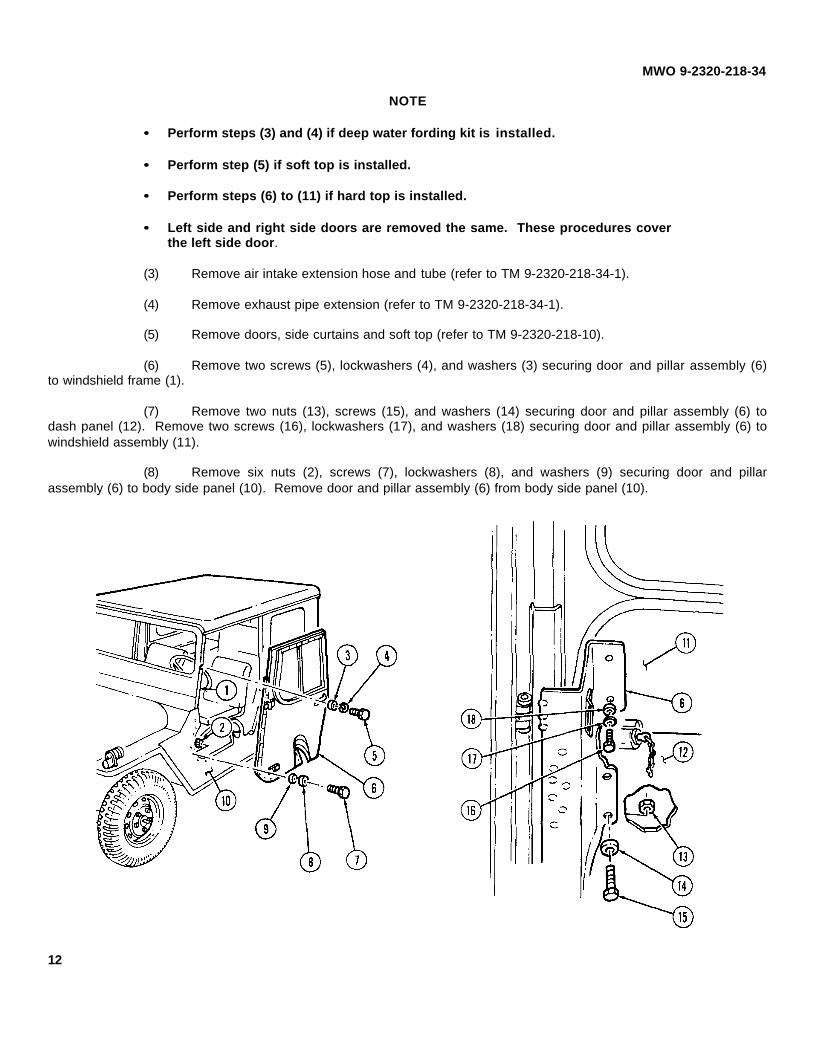
(6) Remove two screws (5), lockwashers (4), and washers (3) securing door and pillar assembly (6)to windshield frame (1).
(7) Remove two nuts (13), screws (15), and washers (14) securing door and pillar assembly (6) todash panel (12). Remove two screws (16), lockwashers (17), and washers (18) securing door and pillar assembly (6) towindshield assembly (11).
(8) Remove six nuts (2), screws (7), lockwashers (8), and washers (9) securing door and pillarassembly (6) to body side panel (10). Remove door and pillar assembly (6) from body side panel (10).
12

MWO 9-2320-218-34
(9) Remove screw (36) securing duct assembly (35) to air intake pipe (37). Remove nuts (34),washers (33), and screws (32) securing duct assembly (35) to vehicle body (38) and hard top rear panel (25). Removeduct assembly (35).
(10) Remove four nuts (23), lockwashers (22), screws (20), and washers (19) securing hard top roofpanel (21) to vehicle windshield frame (24). Discard lockwashers.
(11) Remove sixteen nuts (29), lockwashers (28), thirty-two flat washers (27), and sixteen screws (26)securing hard top rear panel (25) to vehicle rear (31) and side panels (30). Discard lockwashers (28). Remove hard topassembly.
(12) Remove windshield (refer to TM 9-2320-218-20-1-2).
(13) Disconnect battery ground cable and reinstall battery box cover (refer to TM 9-2320-218-20-1-1).
13

MWO 9-2320-218-34
(14) Remove screw (1), lockwasher (2), lever (3), nut (4), lockwasher (5), and instruction plate (6)securing ignition switch (7) to dash panel (8). Pull ignition switch (7) from behind dash panel (8). Discard lockwashers (2)and (5).
(15) Remove screw (9), washer (10), lever (11), four screws (14), and lockwashers (13) securing mainlight switch (12) to dash panel (8). Pull main light switch (12) from behind dash panel (8). Discard lockwashers (13).
(16) Remove two screws (15) securing instruction plate (16) and heater switch (17) to dash panel (8).Pull heater switch (17) from behind dash panel (8).
14

MWO 9-2320-218-34
NOTE
Perform steps (17) and (18) if M16 rifle mounting kit is installed.
(17) Remove hot water heater if installed (refer to TM 9-2320-218-20-1-2).
(18) Remove left side and right side rifle mounting catch and floor bracket (refer to TM 9-2320-218-20-1-2).
(19) Remove four rivets (19) securing data plate (18) to vehicle dash panel (8). Remove data plate(18).
(20) Remove rear wheels (refer to TM 9-2320-218-20-1-2).
(21) Remove left rear red reflector (refer to TM 9-2320-218-20-1-2).
NOTE
Prior to removal, tag leads for installation.
(22) Remove trailer receptacle (refer to TM 9-2320-218-20-1-1).
15

MWO 9-2320-218-34
WARNING
•• Remove flammable materials, such as spilled fuel, oil, or rust-proofing fromimmediate area. Place wet rags or nonflammable cloth around area being cut.
•• Use effective chip guarding and personal protective equipment(goggles/shield, gloves, etc.) during cutting operations. Failure to do so couldresult in personal injury.
(23) Using a cutting torch (or air chisel, if available) cut and remove center sections (1) from underwheelhousing supports (2). Bend bottom flanges (4) toward rear of wheelhousing (3). If a torch is used, make certain theWARNING regarding flammable materials is followed prior to use of the torch.
16

MWO 9-2320-218-34
WARNING
•• Remove flammable materials, such as spilled fuel, oil, or rust-proofing fromimmediate area. Place wet rags or nonflammable cloth around area to beflattened.
•• Use effective chip guarding and personal protective equipment(goggles/shield, gloves, etc.) during heating operations. Failure to do so couldresult in personal injury.
(24) Use heat, dolly block, and hammer to flatten two creases (6) on top of wheelhousings (5), to allowaccess for rear rollbar bracket and to allow as much contact as possible between the bracket to be installed and body.
17

MWO 9-2320-218-34
b. 12356649-1 LEFT SIDE REAR ROLLBAR BRACKET INSTALLATION PROCEDURES.
NOTE
•• Perform step 1 only for vehicles equipped with antenna mounting bracket.
•• Perform steps 2 and 3 only for vehicles equipped with deep water fording kit.
(1) Remove four nuts (2) and screws (1) from corner of antenna mounting bracket (3).
(2) Remove three nuts (7) and screws (5) from exhaust mounting support assembly (6).
(3) Cut and remove lower mounting tab (8) from support assembly (6).
(4) Position rollbar bracket ( 11) between wheelhousing (9) and rear body panel flange (12).
(5) Using rollbar bracket (11) as template, locate and mark seven 0.406-inch diameter holes (10) inwheelhousing (9) and two 0.406-inch diameter holes (13) in rear body panel flange (12).
(6) Remove rollbar bracket (11) from wheelhousing (9).
NOTE
If antenna mounting bracket or exhaust mounting support assembly is installed,drill through as marked in step 5.
(7) Drill nine 0.125-inch diameter pilot holes from underside of wheelhousing and enlarge nine pilotholes with 0.406-inch diameter drill from outside of wheelhousing (9), and antenna mounting bracket holes (4) or exhaustmounting support assembly holes (4).
18

MWO 9-2320-218-34
19
MWO 9-2320-218-34
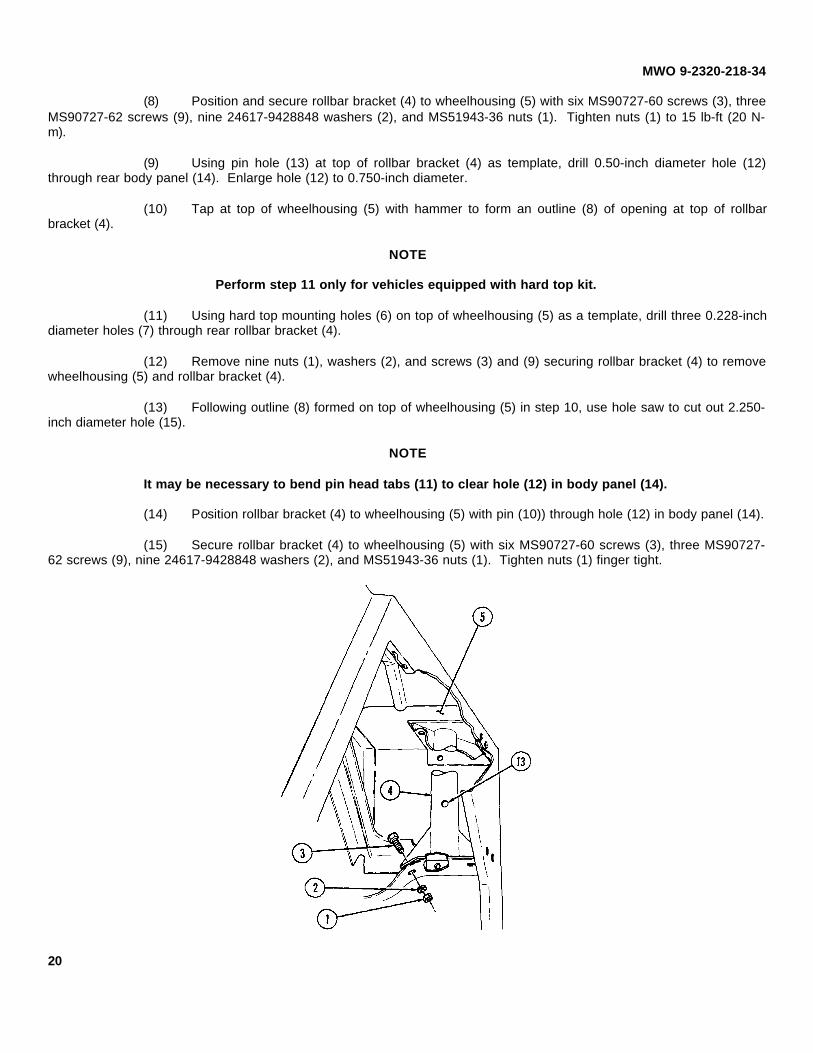
(8) Position and secure rollbar bracket (4) to wheelhousing (5) with six MS90727-60 screws (3), threeMS90727-62 screws (9), nine 24617-9428848 washers (2), and MS51943-36 nuts (1). Tighten nuts (1) to 15 lb-ft (20 N-m).
(9) Using pin hole (13) at top of rollbar bracket (4) as template, drill 0.50-inch diameter hole (12)through rear body panel (14). Enlarge hole (12) to 0.750-inch diameter.
(10) Tap at top of wheelhousing (5) with hammer to form an outline (8) of opening at top of rollbarbracket (4).
NOTE
Perform step 11 only for vehicles equipped with hard top kit.
(11) Using hard top mounting holes (6) on top of wheelhousing (5) as a template, drill three 0.228-inchdiameter holes (7) through rear rollbar bracket (4).
(12) Remove nine nuts (1), washers (2), and screws (3) and (9) securing rollbar bracket (4) to removewheelhousing (5) and rollbar bracket (4).
(13) Following outline (8) formed on top of wheelhousing (5) in step 10, use hole saw to cut out 2.250-inch diameter hole (15).
NOTE
It may be necessary to bend pin head tabs (11) to clear hole (12) in body panel (14).
(14) Position rollbar bracket (4) to wheelhousing (5) with pin (10)) through hole (12) in body panel (14).
(15) Secure rollbar bracket (4) to wheelhousing (5) with six MS90727-60 screws (3), three MS90727-62 screws (9), nine 24617-9428848 washers (2), and MS51943-36 nuts (1). Tighten nuts (1) finger tight.
20

MWO 9-2320-218-34
21

MWO 9-2320-21 8-34
c. 12356649-2 RIGHT SIDE REAR ROLLBAR BRACKET INSTALLATION PROCEDURES.
NOTE
Perform step 1 only for vehicles equipped with antenna mounting bracket.
(1) Remove four nuts (3) and screws (4) from corner of antenna mounting bracket (2).
(2) Position rollbar bracket (6) between wheelhousing (5) and rear body panel flange (7).
(3) Using rollbar bracket (6) as template, locate and mark seven 0.406-inch diameter holes (1) inwheelhousing (5) and two 0.406-inch diameter holes (8) in rear body panel flange (7).
(4) Remove rollbar bracket (6) from wheelhousing (5).
NOTE
If antenna mounting bracket is installed, drill through as marked in step 3.
(5) Drill nine 0.125-inch diameter pilot holes (1) and (8) from underside of wheelhousing (5) andenlarge nine pilot holes (1) and (8) with 0.406-inch diameter drill from outside of wheelhousing (5) and antenna mountingbracket (2).
22
MWO 9-2320-218-34
23

MWO 9-2320-218-34
(6) Position and secure rollbar bracket (2) to wheelhousing (1) with six MS90727-60 screws (3), threeMS90727-62 screws (9), nine 24617-9428848 washers (4), and MS51943-36 nuts (5). Tighten nuts (5) to 15 lb-ft (20 N-m).
(7) Using pin hole (11) at top of rollbar bracket (2) as template, drill 0.50-inch diameter hole (12)through rear body panel (14). Enlarge hole (12) to 0.750-inch diameter.
(8) Tap at top of wheelhousing (1) with hammer to form an outline (8) of opening at top of rollbarbracket (2).
NOTE
Perform step 9 only for vehicles equipped with hard top kit.
(9) Using hard top mounting holes (7) on top of wheelhousing (1) as template, drill 0.228-inchdiameter holes (6) through rear rollbar bracket (2).
(10) Remove nine nuts (5), washers (4), and screws (3) and (9) securing rollbar bracket (2) towheelhousing (1) and remove rollbar bracket (2).
(11) Following outline (8) formed on top of wheelhousing (1) in step 8, use hole saw to cut out 2.250-inch diameter hole (10).
NOTE
It may be necessary to bend pin head tab (15) to clear hole (12) in body panel (14).
(12) Position rollbar bracket (2) to wheelhousing (1) with pin (13) through hole (12) in body panel (14).
(13) Secure rollbar bracket (2) to wheelhousing (1) with six MS90727-60 screws (3), three MS90727-62 screws (9), nine 24617-9428848 washers (4), and MS51943-36 nuts (5). Tighten nuts (5) finger tight.
24

MWO 9-2320-218-34
25

MWO 9-2320-218-34
d. RIGHT-HAND 12356648-2 INTERMEDIATE BRACKET INSTALLATION PROCEDURES.
(1) Raise stowage box cover (1) to OPEN position.
NOTE
For vehicles with arctic insulation installed, use intermediate brackets as templateto locate, mark, and cut away insulation from bracket mounting surface.
(2) Position intermediate bracket (4) to front of wheelhousing (5) and body side panel (11).
(3) Using intermediate bracket (4) as a template, locate and mark six 0.406-inch diameter holes (3).
(4) Remove intermediate bracket (4).
(5) Drill six 0.406-inch diameter holes (3).
(6) Position and secure intermediate bracket (4) to body (10) with four MS90727-62 screws (6), twoMS90727-60 screws (9), six 24617-9428848 washers (7), and six MS51943-36 nuts (8). Tighten nuts (8) finger tight.
(7) Cut a 1.87-inch x 4.25-inch square slot (2) in stowage box cover (1). Remove sharp edges andburrs.
26

MWO 9-2320-218-34
e. LEFT-HAND 12356648-1 INTERMEDIATE BRACKET INSTALLATION PROCEDURES.
(1) Remove screw (19) securing fuel tank (18) to body (17).
(2) Remove fire extinguisher (16) from mounting bracket (13).
(3) Remove four nuts (20), washers (14), and screws (15) securing mounting bracket (13) towheelhousing (12). Remove mounting bracket (13).
27

MWO 9-2320-218-34
NOTE
For vehicles with arctic insulation installed, use intermediate bracket as templateto locate, mark, and cut away insulation from bracket mounting surface.
(4) Position intermediate bracket (2) to front of wheelhousing (1) and body side panel (6).
(5) Using intermediate bracket (2) as a template, locate and mark five 0.406-inch diameter holes (3).
(6) Remove intermediate bracket (2).
(7) Drill five 0.406-inch diameter holes (3) in body (6) and one 0.406-inch diameter hole (5) throughfuel tank mounting weld nut (4).
(8) Position and secure intermediate bracket (2) to body (6) with four MS90727-62 screws (7), twoMS90727-60 screws (10), six 24617-9428848 washers (8), and six MS51943-36 nuts (9). Tighten nuts (9) finger tight.
28

MWO 9-2320-218-34
29

MWO 9-2320-21 8-34
f. FRONT ROLLBAR BRACKETS INSTALLATION PROCEDURES.
NOTE
•• Left-hand 12356647-2 and right-hand 12356647-1 rollbar brackets are installedthe same. This procedure covers the left-hand rollbar bracket.
•• For vehicles with arctic insulation installed, use rollbar bracket as template tolocate, mark, and cut away insulation from bracket mounting surface.
(1) Position rollbar bracket (5) against front floor panel (3) and body side panel (1).
(2) Using rollbar bracket (5) as template, locate and mark four 0.406-inch diameter holes in floorpanels (14) and (3) and two 0.406-inch diameter holes (2) in body side panel (1).
(3) Remove rollbar bracket (5) and drill six 0.125-inch diameter pilot holes (2) and (4) as marked instep 2.
NOTE
Make sure two pilot holes (7) are centered on underbody crossmember (6) flange.If not centered, reposition rollbar bracket (5), remark and drill new pilot holes.
(4) Enlarge six pilot holes (2) and (4) with 0.406-inch diameter drill.
(5) Install and secure rollbar bracket (5) to front floor panel (3) with two MS90727-60 screws (1:3),24617-9428848 washers (9), and MS51943-36 nuts (10). Tighten nuts finger tight.
NOTE
It may be necessary to reform bottom of shovel support ( 11) to allow access formounting hardware.
(6) Secure rollbar bracket (5) to body side panel (1) with two MS90727-58 screws (8), 24617-9428848 washers (9), and MS51943-36 nuts (10). Tighten nuts finger tight.
(7) Secure rollbar bracket (5) to floor (14) with two MS90727-62 screws (12), 24617-9428848washers (9), and MS51943-36 nuts (10). Tighten nuts finger tight.
30

MWO 9-2320-218-34
31

MWO 9-2320-218-34
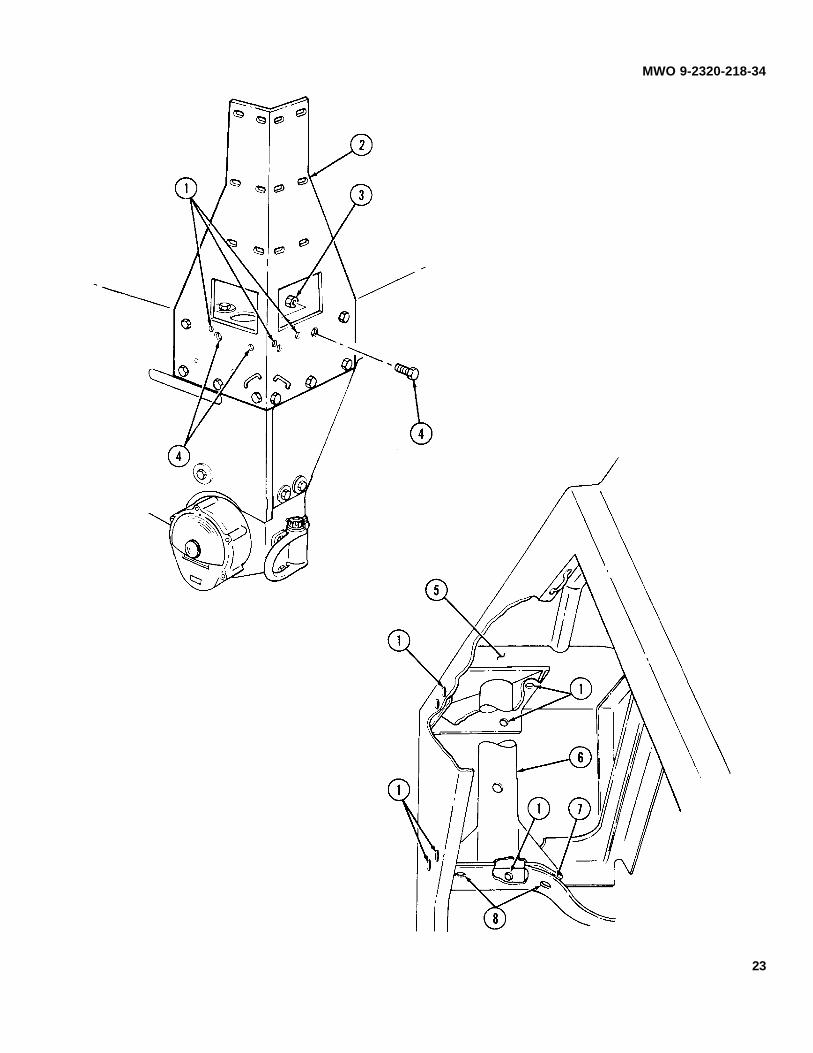
g. LIGHT SWITCH REINFORCEMENT INSTALLATION PROCEDURES.
(1) Using 12356650 reinforcement (8) as template, locate and aline the two holes (12) on left side ofreinforcement (8) with the left two existing light switch mounting holes (2) and (13) on dash panel (3).
(2) Locate and mark light switch opening (9) and main power switch holes (11) on dash panel (3).
(3) Remove reinforcement (8) and drill the following holes in dash panel (3).
(a) One 0.128-inch diameter hole (4).
(b) One 0.562-inch diameter hole (5).
(c) Four 0.228-inch diameter holes (7).
(d) Cut out light switch opening (6) using 2.50-inch diameter hole saw.
(4) Install reinforcement (8) to dash panel (3) and secure with two MS35207-264 screws (10) andMS21044-N3 nuts (1).
32

MWO 9-2320-218-34
h. RIGHT SIDE REINFORCEMENT INSTALLATION.
NOTE
Perform steps (1) through (5) if M16 rifle mounting brackets are installed.
(1) Remove nut (21), washer (20), and screw (27) securing passenger grab handle (16) to vehicledash panel (3).
(2) Using 12356650 reinforcement (10) as a template, aline hole (17) with hole (18) in dash panel (3).
(3) Locate, mark, and drill two 0.348-inch diameter holes (19) and four 0.228-inch diameter holes(22) in dash panel (3).
(4) Install and secure reinforcement (10) to dash panel (3) with four MS35207-264 screws (25),MS35335-33 washers (24), and MS21044-N3 nuts (23).
(5) Secure passenger grab handle (16) to vehicle dash (3) and reinforcement (10) with existing screw(27), washer (20), and MS21042-4 nut (21).
33

MWO 9-2320-21 8-34
i. ROLLBAR ASSEMBLY INSTALLATION.
NOTE
Note direction of pin assemblies.
(1) Attach 12356641-1 rollbar (1) to 12356644-2 rollbar (3) and secure with pin assembly (2).
(2) Attach 12356653 rollbar (5) to 12356642 rollbar (6) and secure with pin assembly (2).
(3) Slide two shoulder strap assemblies (10) onto 12356654 rollbar (8) and 12356643 rollbar (9), andattach rollbars together and secure with pin assembly (2).
(4) Install front rollbar assembly (A) into front mounting brackets (11).
(5) Insert two 12356644-1 crossbars (4) into rollbar (A) assembled in step (1).
(6) Install intermediate rollbar assembly (B) into intermediate brackets (12).
(7) Install two 12356667 front seat belt assemblies (18) on intermediate rollbar (B).
(8) Insert two 12356641-2 crossbars (7) into rollbar (B) assembled in step (2).
(9) Install rear rollbar assembly (C) into rear brackets (13).
(10) Install crossbars (4) and (7) and secure with eight pin assemblies (14).
(11) Secure front (A), intermediate (B), and rear (C) rollbar assemblies to brackets with pin assemblies(15).
(12) Tighten all mounting hardware nuts (16) securing front (11), intermediate (12), and rear (15)rollbar brackets to vehicle (17). Tighten nuts (16) to 30-40 lb-ft (41-54 N-m)
34

MWO 9-2320-21 8-34
35

MWO 9-2320-218-34
j. FRONT SEAT BELT ASSEMBLY INSTALLATION.
NOTE
•• Left and right-hand seat belts are installed the same. This procedure coversthe right-hand belt assembly.
•• Note position of stop block (10) on left-hand bracket (11).
•• Note position of pin (4) on shoulder belt retractor (3).
(1) Install and secure shoulder belt retractor (3) to 12368352 bracket (11) with MS90727-86 screw(6), MS27183-16 washer (5), and MS51988-10 nut (1). Tighten nut (1) 60 lb-ft (81 N-m).
(2) Secure bracket (11) and front belt retractor (9) to intermediate rollbar (2) with MS90727-112screw (7) and MS27183-18 washer (8). Tighten screw (7) to 60 lb-ft (81 N-m).
(3) Install and secure 12356660 anchor (12) to existing holes (16) in vehicle floor (14) with MS90727-86 screw (6), 12301256 anchor (15), MS27183-16 washer (5), and MS51988-10 nut (1). Tighten nut (1) to 60 lb-ft (81 N-m).
(4) Install and secure seat belt assembly half with buckle (9) to floor anchor bracket (12) withMS90727-110 screw (17), MS27183-18 washer (8), and MS51988-12 nut (13). Tighten nut (13) to 90 lb-ft (122 N-m).
36

MWO 9-2320-218-34
37

MWO 9-2320-218-34
k. REAR SEAT BELT ASSEMBLY INSTALLATION.
NOTE
•• Left and right-hand seat belts are installed the same. This procedure coversthe left-hand seat belt assembly.
•• Perform steps 4 and 9 only for left-hand seat belt installation.
(1) Remove and discard two top nuts (1), existing washers, and screws (7) securing pintle assembly(6) to vehicle body (8).
(2) Install and secure 12356663 bracket (9) to vehicle body (8) and pintle assembly (6) with twoMS90727-118 screws (7) and MS51988-12 nuts (1). Tighten nuts (1) to 30-40 lb-ft (41-54 N-m).
(3) Secure 12356668 belt assembly half with buckle (3) to bracket (9) with MS90727-1 10 screw (4),MS27183-18 washer (5), and MS51988-12 nut (2). Tighten nut (2) to 30-40 lb-ft (41-54 N-m).
(4) Pull harness (12) away from two clips (11) under rear body (10).
38

MWO 9-2320-218-34
(5) Locate, mark, and drill two 0.468-inch diameter holes (13) in body flange (14).
(6) Install MS27183-16 washer (24) and MS90727-86 screw (25) to short leg (26) of 12301273bracket (22).
(7) Attach shoulder strap (17) to belt assembly (16) attached to rear rollbar assembly (15). Installand secure belt assembly half with retractor (18), and shoulder strap (17) to bracket (22) with MS27183-18 washer (21),MS90727-112 screw (23), and MS51988-12 nut (19). Tighten nut (19) to 30-40 lb-ft (41-54 N-m).
(8) Install and secure bracket (22) to vehicle body (27) with MS51988-10 nut (20). Tighten nut (20)to 30-40 lb-ft (41-54 N-m).
(9) Secure harness (12) to rear underbody (10) with two existing clips (11).
(10) Secure shoulder belt buckles (28) to seat belt buckles (29) with existing locking rings (30).
39

MWO 9-2320-218-34
l. TRAILER RECEPTACLE REINFORCEMENT INSTALLATION.
(1) Using 12356651 reinforcement (7) as a template, aline two holes (6) in reinforcement (7) with twoholes (4) in rear body panel (3).
(2) Locate, mark, and drill three 0.281-inch diameter holes (5) and (2) in rear body panel (3).
(3) Locate, mark, and cut one 2.25-inch diameter hole (1) in rear body panel (3).
(4) Secure reinforcement (7) to rear body panel (3) with MS35206-281 screw (8), MS35335-33washer (9), and MS51967-2 nut (10).
(5) Install NAS451-17 plug (12) in left-hand pin assembly hole (11).
(6) Install NAS451-17 plug (14) in right-hand pin assembly hole (13).
40

MWO 9-2320-218-34
m. FRONT RESTRAINT INSTALLATION.
NOTE
Left and right-hand restraints are installed the same. This procedure covers theleft-hand restraint.
(1) Install and secure 12356671-2 restraint (18) top mounting strap with buckle (21) to intermediaterollbar (22) with MS90727-121 screw (23), two MS27183-18 washers (20), and MS51988-12 nut (19). Tighten nut (19) to90 lb-ft (122 N-m).
(2) Install and secure 12368353 bracket (28) to lower part of front rollbar (17) with two MS90727-31Lscrews (29). Tighten screws (29) to 24 lb-ft (32 N-m).
(3) Remove two latches (15) from restraint (18) and secure upper latch (15) to front rollbar (17) withtwo MS90727-29L screws (27). Tighten screws (27) to 24 lb-ft (32 N-m).
(4) Secure lower latch (15) to bracket (28) with two MS90727-33 screws (31) and MS51988-6 nuts(30). Tighten nuts (30) to 24 lb-ft (32 N-m)
(5) Secure front restraint, top and bottom straps (16) to latches (15) on front rollbar (17).
(6) Secure three remaining straps (24) to intermediate rollbar (22).
(7) Secure bottom strap (26) through footman loop (25) on intermediate rollbar (22).
41

MWO 9-2320-218-34
n. ROLLBAR PADDING INSTALLATION.
NOTE
•• Use drycleaning solvent to clean rollbar surface before installing padding.
•• Trim starting end of 12356670 padding at 45o for square fit before wrappingrollbars.
(1) Position and secure 212-inch roll of padding (1) to rear rollbar (8) by starting at point (A) andwrapping rollbar with padding (1) toward point (B). Use additional padding (6) until point (B) is reached. Trim end ofpadding (1) for square fit.
(2) Cover all padding (1) with PPP-T-60 tape (9) spiral wrapped at right angles to padding (1) with1.00-inch overlap (10) starting at point (B).
(3) Cut and remove padding ( 1 ) from outside rollbar areas (3) to allow access to footman loops (4)for rear restraint installation.
(4) Position and secure 212-inch roll of padding (1) to intermediate rollbar (5) by starting at point (C)and wrapping rollbar with padding (1 ) until point (D) is reached. Trim end of padding (1) for square fit. Use additionalpadding (1 ) around front restraint buckle (2) and screw head (7) if required.
(5) Cover all padding (1) with PPP-T-60 tape (9) spiral wrapped at right angles to padding (1) with1.00-inch overlap (10) starting at point (D).
(6) Cut and remove padding ( 1 ) from outside rollbar areas (3) to allow access to footman loops (4)for rear restraint installation.
42

MWO 9-2320-218-34
NOTE
For the following steps, cut two 212-inch rolls of padding in half.
(7) Position and secure 106-inch roll of padding (11) to front left crossbar (12) by starting at point (E)and wrapping bar with padding (11) until point (F) is reached. Trim end of padding (11).
(8) Position and secure 106-inch roll of padding (11) to front right crossbar (13) by starting at point(G) and wrapping bar (13) with padding (11) until point (H) is reached. Trim end of padding (11) for square fit.
(9) Position and secure 106-inch roll of padding (11) to rear left crossbar (19) by starting at point (I)and wrapping bar (19) with padding (11) until point (J) is reached. Trim end of padding (11) for square fit.
(10) Position and secure 106-inch roll of padding (11) to rear right crossbar (15) by starting at point (K)and wrapping bar (15) with padding (11) until point (L) is reached. Trim end of padding (11) for square fit.
(11) Use additional padding (11) around inside of rollbar areas (14) if required.
(12) Cover all padding (11) with PPP-T-60 tape (16) spiral wrapped at right angles to padding (11)with 1.00-inch overlap (17).
43

MWO 9-2320-218-34
o. REAR RESTRAINT INSTALLATION.
NOTE
Left and right-hand restraints are installed the same. This procedure covers theleft-hand restraint.
(1) Install and secure 12356672-1 restraint (3) upper straps (1) to footman loops (5) on intermediate(2) and rear (4) rollbars.
(2) Install and secure restraint (3) lower straps (7) to footman loops (8) on intermediate (2) and rear(4) rollbars.
(3) Secure remaining straps (6) to intermediate (2) and rear (4) rollbars.
44

MWO 9-2320-218-34
p. HARD TOP DOOR HANDLE INSTALLATION.
NOTE
•• Perform this procedure only if hard top kit is installed on vehicle.
•• Left and right door handles are installed the same. Procedure covers the leftdoor handle.
(1) Remove cotter pin (8), slotted nut (4), and lockwasher (3) securing inner door handle (2) to door(1). Discard cotter pin (8).
(2) Remove and discard door handle (2).
(3) Install and secure 12356652-1 handle (2) to door (1) with MS35338-48 washer (3), existingslotted nut (4), and MS24665-287 cotter pin (8).
(4) Remove two screws (7) and washers (6) securing door handle stop (5) to door (1). Remove doorstop (5).
(5) Cut and form inside edge (9) of door handle stop (5).
(6) Install and secure door handle stop (5) to door (1) with two existing screws (7) and washers (6).
45

MWO 9-2320-218-34
q. DATA PLATE INSTALLATION.
(1) Using existing data plate (12) as template, locate, mark, and drill four 0.125-inch diameter holes(10) in dash panel (14) behind passenger grab handle (11).
(2) Install and secure existing data plate (12) to dash panel (14) with two lower MS51861-44 screws(13). Install 12368354 data plate (18) over existing data plate (12) and secure with two upper MS51861-44 screws (13).
(3) Remove four screws (15) securing data plate (16) to right side front wheelhousing (17). Removeand discard data plate (16) and four screws (15).
(4) Install 12356673 data plate (16) to right side front wheelhousing (17) and secure with fourMS51861-44 screws (15).
46

MWO 9-2320-218-34
r. FIRE EXTINGUISHER INSTALLATION.
(1) Using fire extinguisher mounting bracket (3) as template, locate, mark, and drill four 0.312-inchdiameter holes (2) in wheelhousing (1).
(2) Install and secure mounting bracket (3) to wheelhousing (1) with four existing screws (5), washers(4), and nuts (6).
s. TRAILER RECEPTACLE INSTALLATION.
(1) Connect harness leads (13) to trailer receptacle (11).
(2) Secure trailer receptacle (11) to body weld nuts (14) with two existing screws (12) and MS35335-33 lockwashers (8).
(3) Secure trailer receptacle (11) and ground lead (9) to body (10) with two existing screws (12),MS35335-:33 lockwashers (8), and two MS51967-2 nuts (7).
47

MWO 9-2320-218-34
t. M16 RIGHT SIDE RIFLE FLOOR MOUNTING BRACKET INSTALLATION.
NOTE
This procedure covers the right side bracket. Left side bracket is not installed withrollbars.
(1) Using bracket (18) as template, locate, mark, and drill two 0.316-inch diameter holes (16) in floorpanel (15).
(2) Secure bracket (18) to floor panel (15) with two existing screws (17), MS35335-33 washers (19),and nuts (20).
48

MWO 9-2320-218-34
u. ELECTRICAL SWITCHES INSTALLATION.
(1) Secure heater switch (4) and identification plate (2) to dash panel (3) with two existing screws (1).
(2) Secure main light switch (8) to dash panel (3) with four MS35333-39 washers (9) and existingscrews (10), and secure lever (7) to switch (8) with existing washer (6) and screw (5).
(3) Secure ignition switch (17) and identification plate (16) to dash panel (3) with MS35333-44washer (15), and existing nut (14), and secure lever (13) to switch (17) with MS35338-42 washer (12) and existing screw(11).
49

MWO 9-2320-218-34
v. INSTALL WINDSHIELD (refer to TM 9-2320-218-20-1-1).
w. HARD TOP KIT INSTALLATION.
NOTE
•• Perform this procedure only for vehicles equipped with hard top kit.
•• It may be necessary to cut and remove padding from intermediate and rearrollbars to allow hard top to clear rollbars.
(1) Cut and remove part of triangular gusset (2) from lower left and right sides of hard top (1).Remove sharp edges and burrs.
50

MWO 9-2320-218-34
(2) Position hard top (1) over vehicle body (10) and windshield (5).
(3) Secure hard top (1) to windshield frame (5) with four existing screws (6), washers (7), nuts (3),and MS35338-45 lockwashers (4).
(4) Secure hard top (1) to vehicle body (10) with ten existing screws (8), washers (9), nuts (12), andMS35338-45 lockwashers ( 11).
(5) Secure hard top (1) to wheelhousings (15) with six MS51851-88 screws (13) and existingwashers (14).
(6) Install and secure duct assembly (16) to hard top (1) and vehicle body (10) with four existingscrews (21), nuts (19), and eight washers (20).
(7) Secure air intake pipe (17) to duct assembly (16) with existing screw (18).
51

MWO 9-2320-218-34
NOTE
Left and right side door and pillar assemblies are installed the same. Theseprocedures cover the left side door and pillar assembly.
(8) Install and secure door and pillar assembly (6) to body side panel (10) with six existing screws(7), washers (9), lockwashers (8), and nuts (2).
(9) Secure door and pillar assembly (6) to (lash panel (12) and windshield panel (11) with twoexisting screws (15), washers (14), and nuts (13), and two existing screws (16), washers (18), and lockwashers (17).
(10) Secure door and pillar assembly (6) to windshield frame (1) with two existing screws (5), washers(3), and lockwashers (4).
52

MWO 9-2320-218-34
x. DEEP WATER FORDING KIT MODIFICATION.
(1) Install and secure 12356658 clamp (27), and 12356659 brace (25) to rollbar (26) with twoMS90726-34 screws (28), MS27183-12 washers (29), and MS21044-N5 nuts (24).
(2) Install air intake extension hose and tube (19) (refer to TM 9-2320-218-34-1).
(3) Discard existing support (22) and secure air intake clamp (21) to brace (25) with existing screw(23) and nut (20).
53

MWO 9-2320-218-34
y. VEHICLE FINAL PREPARATION.
(1) Prime and paint exposed metal surfaces as required (refer to TB 43-0209 and TM 43-0039).
(2) Apply rustproofing as required (refer to TB 43-0213).
(3) Install left rear red reflector (refer to TM 9-2320-218-20-1-2).
(4) Install rear wheels (refer to TM 9-2320-218-20-1-2).
NOTE
Perform steps (5) and (6) if M16 mounting catches were removed.
(5) Install left and right side rifle mounting catch (refer to TM 9-2320-218-1-2).
(6) Install hot water heater if removed (refer to TM 9-2320-218-1-2).
(7) Connect battery ground cable (refer to TM 9-2320-218-20-1-1).
(8) Install rear seat (refer to TM 9-2320-218-20-1-2).
(9) Install front seats (refer to TM 9-2320-218-20-1-2).
(10) Install soft top, side curtains, and doors, if removed (refer to TM 9-2320-218-10).
(11) Adjust front seat belts with retractor to desired position and tighten screws securing front seatbelts with retractor to intermediate rollbar to 60 lb-ft (81 N-m).
NOTE
Use drycleaning solvent to clean windshield surface before applying warning label.
(12) Apply 1235676.3 warning label (1) to lower windshield frame (2), centered over instrument panel(3).
54

MWO 9-2320-218-34
t. M16 RIGHT SIDE RIFLE FLOOR MOUNTING BRACKET INSTALLATION.
NOTE
This procedure covers the right side bracket. Left side bracket is not installed withrollbars.
(1) Using bracket (18) as template, locate, mark, and drill two 0.316-inch diameter holes (16) in floorpanel (15).
(2) Secure bracket (18) to floor panel (15) with two existing screws (17), MS35335-33 washers (19),and nuts (20).
14. QUALITY ASSURANCE REQUIREMENTS.
a. GENERAL. The following information is supplied to ensure the proper application of this modification andprovide clarification in regard to the adequacy of installer's inspection methods and procedures applicable to qualityassurance contract data. The provisions include, but are not limited to, installer responsibilities, Government verification,in-process inspection and workmanship inspection. Inspection shall be in accordance with TM 750-245-4.
b. INSTALLER RESPONSIBILITIES. The installer is responsible for compliance with quality assurancerequirements specified herein. These requirements, the installer's plan of inspection, or quality program, constitute theminimum examinations and tests necessary to assure compliance with established requirements. Requirementscontained in this MWO shall be included in the installer's inspection plan or quality program. These requirements shall notbe construed as eliminating the installer's responsibility from complete compliance with all the provisions of the contractand submitting to the Government, material that meets all requirements of the contract.
c. GOVERNMENT VERIFICATION. All quality assurance operations performed by the installer shall besubject to Government verification at unscheduled intervals. Verification will consist of (A) surveillance of the operationsto determine that practices, methods and procedures of the written inspection plan are being properly applied, and (B)Government product inspection to measure quality of product offered for acceptance deviation from prescribed or agreed-upon procedures or instances of practices which might have an adverse effect upon the quality of the product, willimmediately be called to the attention of the installer. Failure of the installer to promptly correct deficiencies noted shall because for suspension of acceptance until corrective action has been made, or until conformance of product to prescribedcriteria has been demonstrated.
d. IN-PROCESS INSPECTION. During normal assembly operations torque procedures used in productionshall be visually observed and readings recorded to determine conformity of the torque requirements contained in thisMWO. The recorded torque readings shall be submitted to the Government as certification of the torque requirements. Aminimum of (4) individual torque performances for each torque requirement shall be observed at random intervals duringeach identified production shift to assure that torque procedure is adequate to attain torque as specified.
e. WORKMANSHIP INSPECTION. Inspect components that were replaced or installed during themodification for security of mounting. Inspect painted areas of ROPS kit and reworked components for missing, cracked,or chipped paint. Prime (MIL-P-52192, MIL-P-53022 or MIL-P-53030) and paint (MIL-C-46168) as required. Inspectcable and lead assemblies for proper and secure routing. Inspect for frays, cracks, splits, or bare wires. Correct ifnecessary. Inspect metal surfaces for burrs or sharp edges. Remove, if present. Inspect for deformations or otherindications of poor workmanship and completeness of assembly. Correct, if necessary.
55

MWO 9-2320-218-34
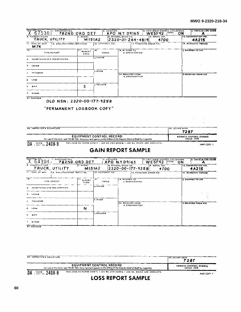
15. RECORDING AND REPORTING OF THE MODIFICATION.
a. Records and report forms (refer to DA PAM 738-750).
b. Loss and gain form 2408-9 will be initiated to report change of end item NSN.
16. PRODUCT IMPROVEMENT PROPOSAL (PIP) NUMBER
1-85-06-4052
56

MWO 9-2320-218-34
APPENDIX
This appendix gives examples of the forms required to be completed upon completion of the MWO.
57

MWO 9-2320-218-34
58

MWO 9-2320-218-34
59
MWO 9-2320-218-34
60

MWO 9-2320-218-34
HEADQUARTERS
U.S. ARMY TANK-AUTOMOTIVE COMMAND
WARREN, MICHIGAN 48397-5000
This publication has been prepared under the supervision and control of the Commander, U.S. Army Tank-Automotive Command, Warren, Michigan, by the Maintenance Directorate, National Maintenance Point (NMP) and ispublished for the information and guidance of all concerned.
FOR THE COMMANDER:
OFFICIAL: JAMES G. EDGEColonel, GSChief of Staff
BRENDA M. STENERSON1LT, GSAdjutant
DISTRIBUTION:Special
¶ U.S. GOVERNMENT PRINTING OFFICE: 1988- 542 - 015/80053


THE METRIC SYSTEM AND EQUIVALENTS
LINEAR MEASURE SQUARE MEASURE
1 Centimeter = 10 Millimeters = 0.01 Meters = 0.3937 Inches 1 Sq Centimeter = 100 Sq. Millimeters = 0.155 Sq Inches1 Meter = 100 Centimeters = 1000 Millimeters = 39.37 Inches 1 Sq. Meter = 10,000 Sq Centimeters = 10.76 Sq Feet1 Kilometer = 1000 Meters = 0.621 Miles 1 Sq Kilometer = 1,000,000 Sq Meters = 0.386 Sq Miles
WEIGHTS CUBIC MEASURE
1 Gram = 0 001 Kilograms = 1000 Milligrams = 0.035 Ounces 1 Cu Centimeter = 1000 Cu Millimeters = 0 06 Cu Inches1 Kilogram = 1000 Grams = 2.2 Lb 1 Cu Meter= 1,000,000 Cu Centimeters = 35 31 Cu. Feet1 Metric Ton = 1000 Kilograms = 1 Megagram = 1.1 Short Tons
LIQUID MEASURE TEMPERATURE5/9 (°F - 32) = °C
1 Milliliter = 0.001 Liters = 0.0338 Fluid Ounces 212° Fahrenheit is equivalent to 100° Celsius1 Liter = 1000 Milliliters = 33.82 Fluid Ounces 90° Fahrenheit is equivalent to 32 2° Celsius320 Fahrenheit is equivalent to 0° Celsius 9/5 (°C + 32) = °F
APPROXIMATE CONVERSION FACTORS
TO CHANGE TO MULTIPLY BYInches ............................................................Centimeters ..................................................................2.540Feet................................................................Meters ...........................................................................0.305Yards .............................................................Meters ...........................................................................0.914Miles ..............................................................Kilometers ....................................................................1.609Square Inches ..............................................Square Centimeters ....................................................6.451Square Feet.................................................Square Meters .............................................................0.093Square Yards ...............................................Square Meters .............................................................0.836Square Miles ...............................................Square Kilometers ......................................................2.590Acres .............................................................Square Hectometers ...................................................0.405Cubic Feet....................................................Cubic Meters................................................................0.028Cubic Yards ..................................................Cubic Meters................................................................0.765Fluid...............................................................Ounces Milliliters ........................................................29.573Pints ..............................................................Liters ..............................................................................0.473Quarts ...........................................................Liters ..............................................................................0.946Quarts. ..........................................................Liters ..............................................................................0.946Gallons ..........................................................Liters ..............................................................................3.785Ounces ..........................................................Grams ...........................................................................28.349Pounds ..........................................................Kilograms......................................................................0.45Short Tons....................................................Metric Tons...................................................................0.0907Pound-Feet...................................................Newton-Meters ............................................................1.356Pounds per Square .....................................Inch Kilopascals ..........................................................6.895Miles per Gallon ..........................................Kilometers per Liter.....................................................0.425Miles per Hour .............................................Kilometers per Hour....................................................1.609
TO CHANGE TO MULTIPLY BYCentimeters ..................................................Inches ............................................................................0.394Meters ...........................................................Feet................................................................................3.280Meters ...........................................................Yards .............................................................................1.094Meters ...........................................................Yards .............................................................................1.094Kilometers ....................................................Miles ..............................................................................0.621Square Centimeters ....................................Square Inches ..............................................................0 155Square Meters .............................................Square Feet . ...............................................................10.764Square Meters ............................................Square Yards ...............................................................1.195Square Kilometers ......................................Square Miles ................................................................0.386Square Hectometers ...................................Acres .............................................................................2.471Cubic Meters................................................Cubic Feet....................................................................35.315Cubic Meters................................................Cubic Yards ..................................................................1.308Milliliters Fluid ..............................................Ounces ..........................................................................0.034Liters ..............................................................Pints ..............................................................................2.113Liters ..............................................................Quarts ...........................................................................1.057Liters ..............................................................Gallons .........................................................................0.264Grams ...........................................................Ounces ..........................................................................0.035Kilograms......................................................Pounds ..........................................................................2 205Metric Tons...................................................Short Tons....................................................................1.102Newton-Meters ............................................Pound-Feet...................................................................0.738Kilopascals ...................................................Pounds per Square Inch ............................................0.145Kilometers per Liter.....................................Miles per Gallon ..........................................................2.354Kilometers per Hour....................................Miles per Hour .............................................................0.621 TA08991

PIN: 063520-000