Embed Size (px)
Citation preview
M110/M800 RTU Installation Instructions
Thank you for choosing Mission, As part of Mission’s commitment to provide you with the highest quality “out of the box” SCADA solutions available, this product and packaging have been thoroughly tested before leaving our manufacturing facility. The first chapters of this guide are “Pre-Installation” and are intended to identify issues and recommend so-lutions to optimize your installation. Please take a few minutes to consider the steps in this guide and con-firm that you have received all the necessary parts for your successful installation, that your RTU is fully functional and that there are no site related connectivity issues to overcome. The steps include: I. Parts and Tools Required II. Site Survey Connectivity Test and Antenna Placement III. RTU Box Installation and Wiring Overview IV. RTU Startup V. Test the Installation VI. Site Commissioning VII.Troubleshooting Appendix I: Specifications Appendix II: Trouble Relay Wiring Diagram Appendix III: Universal Antenna Mount A few minutes now may save you time and effort! Remember our technical support staff is available at 877-993-1911 for further assistance. Thanks, MISSION COMMUNICATIONS, LLC
MIS
SIO
N C
IRC
UIT
BO
AR
D
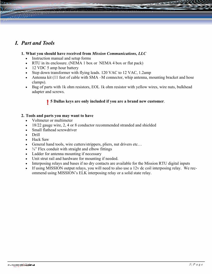
I. Part and Tools
1. What you should have received from Mission Communications, LLC Instruction manual and setup forms RTU in its enclosure. (NEMA 1 box or NEMA 4 box or flat pack) 12 VDC 5 amp hour battery Step down transformer with flying leads. 120 VAC to 12 VAC, 1.2amp Antenna kit (11 feet of cable with SMA –M connector, whip antenna, mounting bracket and hose
clamps). Bag of parts with 1k ohm resistors, EOL 1k ohm resistor with yellow wires, wire nuts, bulkhead
adapter and screws.
5 Dallas keys are only included if you are a brand new customer.
2. Tools and parts you may want to have
Voltmeter or multimeter 18/22 gauge wire, 2, 4 or 8 conductor recommended stranded and shielded Small flathead screwdriver Drill Hack Saw General hand tools, wire cutters/strippers, pliers, nut drivers etc… ¾” Flex conduit with straight and elbow fittings Ladder for antenna mounting if necessary Unit strut rail and hardware for mounting if needed. Interposing relays and bases if no dry contacts are available for the Mission RTU digital inputs If using MISSION output relays, you will need to also use a 12v dc coil interposing relay. We rec-
ommend using MISSION’s ELK interposing relay or a solid state relay.
3 | P a g e
4 | P a g e
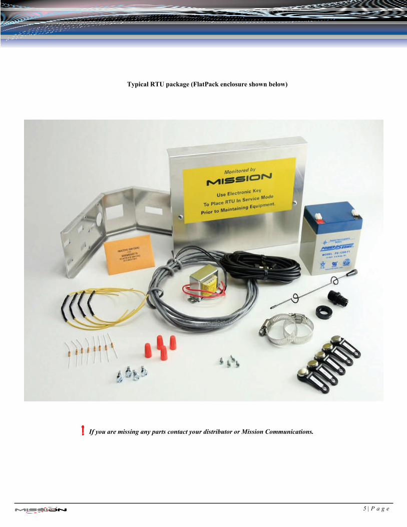
Typical RTU package (FlatPack enclosure shown below)
If you are missing any parts contact your distributor or Mission Communications.
5 | P a g e
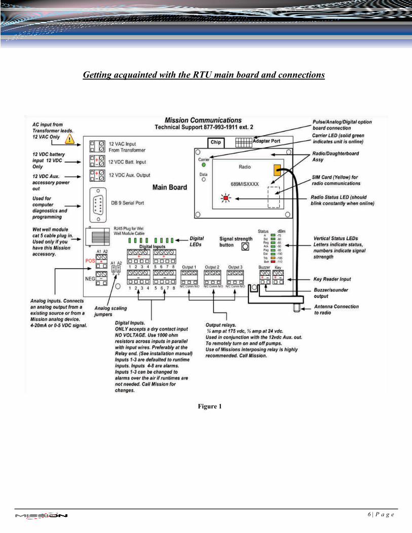
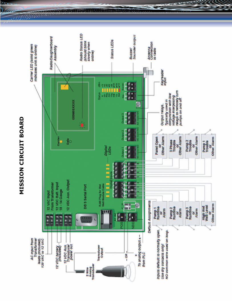
Getting acquainted with the RTU main board and connections
Figure 1
6 | P a g e
II. Site Survey and Connectivity
By powering up the RTU and testing connectivity before mounting the hardware you can optimize the signal strength for years of trouble free communications. The test only takes a few min-utes since the included battery can provide temporary power.
Refer to Figure 1 for the various LEDs and inputs during installation.
AT THE SITE
1. Remove the RTU from its box and place it on or near the control panel it will be
monitoring. 2. Remove the antenna cable and whip antenna from its package and screw the connector into the
RTU’s radio connection. (See figure 2). DO NOT OVER TIGHTEN 3. Screw the whip antenna onto its base and then temporarily get it as high as possible
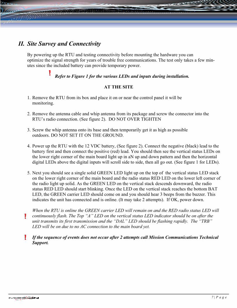
outdoors. DO NOT SET IT ON THE GROUND. 4. Power up the RTU with the 12 VDC battery, (See figure 2). Connect the negative (black) lead to the
battery first and then connect the positive (red) lead. You should then see the vertical status LEDs on the lower right corner of the main board light up in aN up and down pattern and then the horizontal digital LEDs above the digital inputs will scroll side to side, then all go out. (See figure 1 for LEDs).
5. Next you should see a single solid GREEN LED light up on the top of the vertical status LED stack
on the lower right corner of the main board and the radio status RED LED on the lower left corner of the radio light up solid. As the GREEN LED on the vertical stack descends downward, the radio status RED LED should start blinking. Once the LED on the vertical stack reaches the bottom BAT LED, the GREEN carrier LED should come on and you should hear 3 beeps from the buzzer. This indicates the unit has connected and is online. (It may take 2 attempts). If OK, power down.
When the RTU is online the GREEN carrier LED will remain on and the RED radio status LED will continuously flash. The Top “A” LED on the vertical status LED indicator should be on after the unit transmits its first transmission and the “DAL” LED should be flashing rapidly. The “TRB” LED will be on due to no AC connection to the main board yet.
If the sequence of events does not occur after 2 attempts call Mission Communications Technical Support.
7 | P a g e
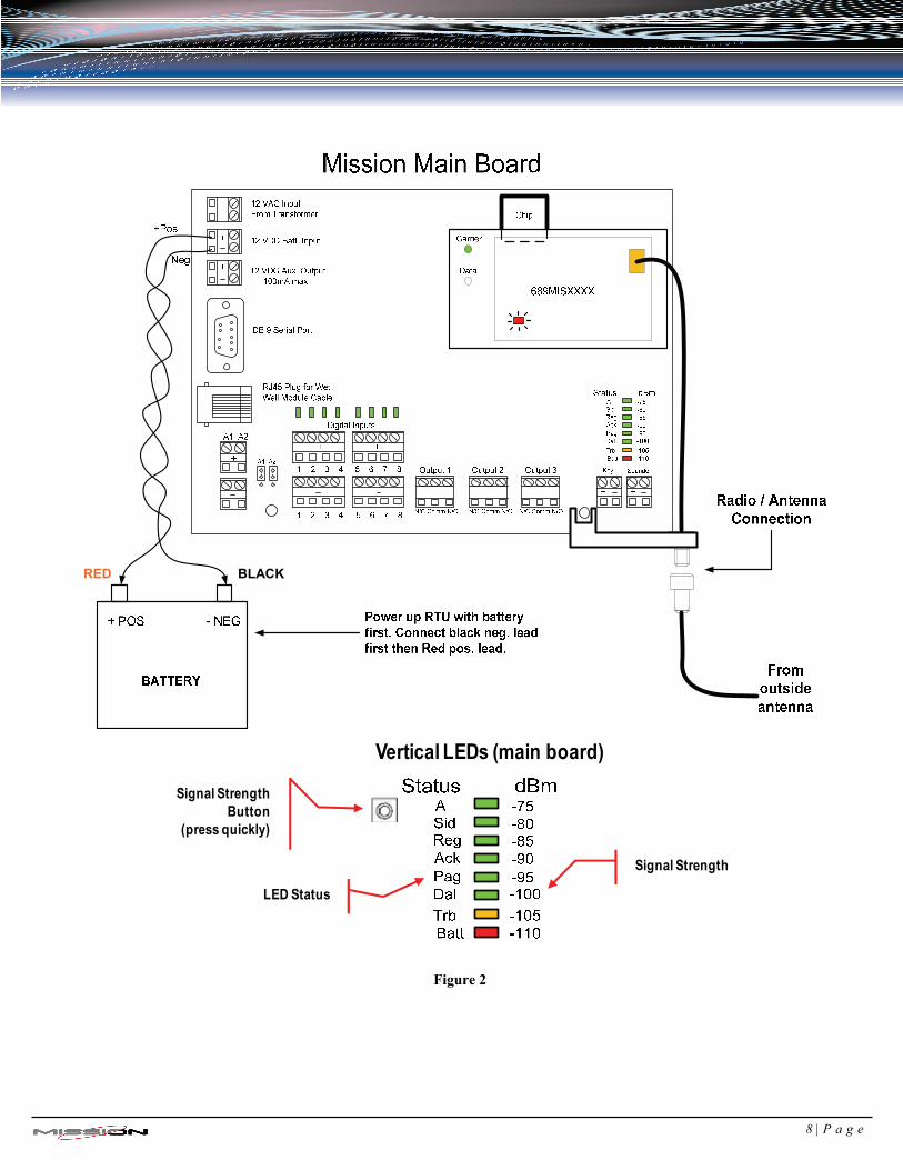
Figure 2
LED Status
Signal Strength
Signal Strength Button
(press quickly)
Vertical LEDs (main board)
RED BLACK
8 | P a g e
III. RTU Box Installation and Wiring Overview
It is highly recommended that station power be off when running wires and connecting to the RTU.
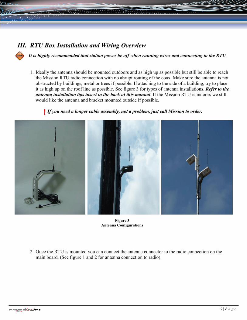
1. Ideally the antenna should be mounted outdoors and as high up as possible but still be able to reach the Mission RTU radio connection with no abrupt routing of the coax. Make sure the antenna is not obstructed by buildings, metal or trees if possible. If attaching to the side of a building, try to place it as high up on the roof line as possible. See figure 3 for types of antenna installations. Refer to the antenna installation tips insert in the back of this manual. If the Mission RTU is indoors we still would like the antenna and bracket mounted outside if possible.
If you need a longer cable assembly, not a problem, just call Mission to order.
Figure 3 Antenna Configurations
2. Once the RTU is mounted you can connect the antenna connector to the radio connection on the main board. (See figure 1 and 2 for antenna connection to radio).
9 | P a g e
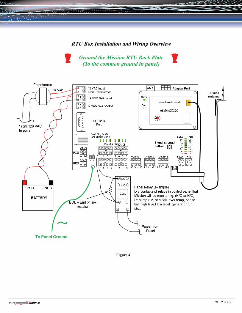
RTU Box Installation and Wiring Overview
Ground the Mission RTU Back Plate (To the common ground in panel)
Figure 4
To Panel Ground
10 | P a g e
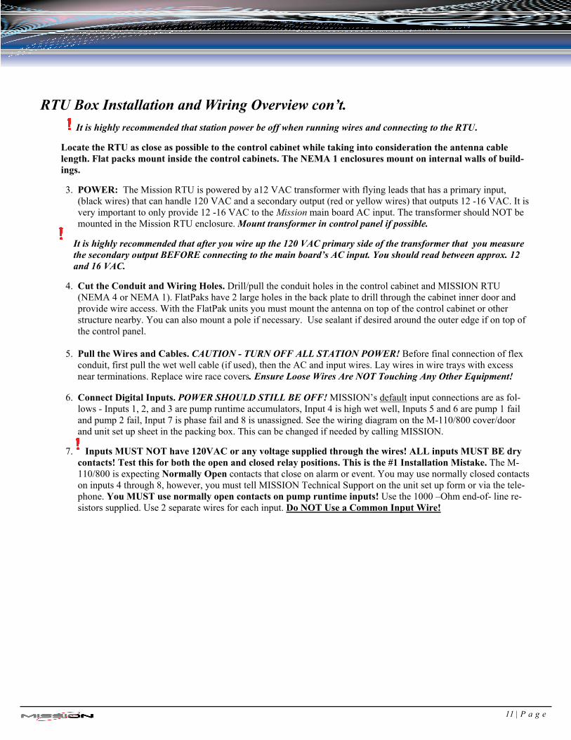
RTU Box Installation and Wiring Overview con’t.
It is highly recommended that station power be off when running wires and connecting to the RTU.
Locate the RTU as close as possible to the control cabinet while taking into consideration the antenna cable length. Flat packs mount inside the control cabinets. The NEMA 1 enclosures mount on internal walls of build-ings.
3. POWER: The Mission RTU is powered by a12 VAC transformer with flying leads that has a primary input, (black wires) that can handle 120 VAC and a secondary output (red or yellow wires) that outputs 12 -16 VAC. It is very important to only provide 12 -16 VAC to the Mission main board AC input. The transformer should NOT be mounted in the Mission RTU enclosure. Mount transformer in control panel if possible.
It is highly recommended that after you wire up the 120 VAC primary side of the transformer that you measure the secondary output BEFORE connecting to the main board’s AC input. You should read between approx. 12 and 16 VAC.
4. Cut the Conduit and Wiring Holes. Drill/pull the conduit holes in the control cabinet and MISSION RTU (NEMA 4 or NEMA 1). FlatPaks have 2 large holes in the back plate to drill through the cabinet inner door and provide wire access. With the FlatPak units you must mount the antenna on top of the control cabinet or other structure nearby. You can also mount a pole if necessary. Use sealant if desired around the outer edge if on top of the control panel.
5. Pull the Wires and Cables. CAUTION - TURN OFF ALL STATION POWER! Before final connection of flex conduit, first pull the wet well cable (if used), then the AC and input wires. Lay wires in wire trays with excess near terminations. Replace wire race covers. Ensure Loose Wires Are NOT Touching Any Other Equipment!
6. Connect Digital Inputs. POWER SHOULD STILL BE OFF! MISSION’s default input connections are as fol-lows - Inputs 1, 2, and 3 are pump runtime accumulators, Input 4 is high wet well, Inputs 5 and 6 are pump 1 fail and pump 2 fail, Input 7 is phase fail and 8 is unassigned. See the wiring diagram on the M-110/800 cover/door and unit set up sheet in the packing box. This can be changed if needed by calling MISSION.
7. Inputs MUST NOT have 120VAC or any voltage supplied through the wires! ALL inputs MUST BE dry contacts! Test this for both the open and closed relay positions. This is the #1 Installation Mistake. The M-110/800 is expecting Normally Open contacts that close on alarm or event. You may use normally closed contacts on inputs 4 through 8, however, you must tell MISSION Technical Support on the unit set up form or via the tele-phone. You MUST use normally open contacts on pump runtime inputs! Use the 1000 –Ohm end-of- line re-sistors supplied. Use 2 separate wires for each input. Do NOT Use a Common Input Wire!
11 | P a g e
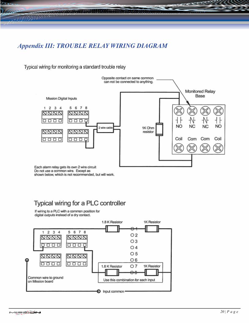
8. RUNTIME AND ALARM WIRING: You can connect your runtime pumps and alarm wires to the digital inputs on the Mission main board. (See figure 1 and 2 for digital inputs) Review the Typi-cal wiring for monitoring a standard trouble relay insert in the back of this manual.
It is important that your digital input wires are connected to dry contacts of the panel re-
lay you are using for an alarm. This means no voltage or current should be present on the wires at anytime going into the MISSION input.
The main board inputs require the use of a 1000 ohm end of line resistor for each digital input used for alarm/event reporting. These resistors are connected to and placed in par-allel with the monitored relay contacts and allow the main board circuitry to monitor the integrity of the connections.
If you cannot easily install the resistors at the relay you can install them across the digital input you are using for that alarm. By doing that you will not have line supervision.
Inputs 1, 2 and 3 are pre programmed at our facility for pump runtime inputs. If you only
use inputs 1 and 2 or you are monitoring just alarms, inputs 1, 2 and 3 can be set to alarm inputs. Call Mission for assistance.
For Model 110 RTUs only. If you are only using inputs 1 and 2 for pump runtimes and you are NOT using input 3 for anything, you can leave the resistor out of input 3 (only this input) and this will then allow you to get simultaneous runtimes of pumps 1 and 2. The data will populate under runtime data on the customer website. Otherwise install the re-sistor in the unused input.
For Model 800, if input 3 is not used install a 1000 ohm resistor across the input. Pump runtime inputs should be wired to the normally open contacts of the runtime relays. Alarm relays can be wired either normally open or normally closed. (If ordered and using a Wet Well Module follow its runtime connection instructions).
MAKE SURE TO GROUND THE MISSION RTU BACK PLATE
Use 8-10 gauge green wire installed to the Mission back plate screw of the RTU or 1 of the 4 screws holding the main board on to the back plate. Do the same with a NEMA 1 enclosure. The Flat Pack will be grounded by the installation onto the panel.
12 | P a g e
IV. RTU START UP
Power the MISSION RTU with its 12 VDC battery only. Do Not Power the Station Yet. Black lead first, then Red (12 VDC). Watch the LEDs to make sure it powers up as previously described. You should then see the vertical status LEDs on the lower right corner of the main board light up in a up and down pattern and then the horizontal digital LEDs above the digital inputs will scroll side to side, then all go out. (See figure 2 for LEDs). Allow the unit adequate time to perform its power-up sequence and synchronization to the network. 5 to10 minutes is generally adequate for the process to successfully conclude. Next you should see a single solid GREEN LED light up on the vertical status LED stack on the lower right corner of the main board and the radio status RED LED on the lower left corner of the radio light up solid. As the GREEN LED on the vertical stack descends downward the radio status RED LED should start blinking. Once the LED on the vertical stack reaches the bottom BAT LED, the GREEN carrier LED should come on and you should hear 3 beeps from the buzzer. This indicates the unit has connected and is online.
When the RTU is online the GREEN carrier LED will remain on and the RED radio status LED will continuously flash. The Top “A” LED on the vertical status LED indicator should be on af-ter the unit transmits its first transmission and the “DAL” LED should be flashing rapidly. The “TRB” LED will be on due to no AC to the main board yet. Once the AC is turned on the “TRB” LED will go out.
Double- Check the Wiring Connections before Re-Powering the Pump Station.
Power the Pump Station and immediately focus on the MISSION Main Board. Check to ensure the MISSION RTU is still operating. If somehow a wiring mistake has been made and 120VAC is be-ing fed to the MISSION RTU main board it will be evident. If there appears to be a mistake, Immedi-ately Power Down the Station before it permanently damages the MISSION RTU unit. If all power is ok, proceed to testing the RTU.
13 | P a g e
V. Test the Installation
It is HIGHLY RECOMMENDED that the following tests be thoroughly done to ensure the Customer or End user gets proper notifications!
1.Test AC. Check the Yellow TRB LED. It should not be on steady. If it is, the MISSION RTU is not
wired properly for 12VAC. If the yellow LED is blinking then one of the alarm inputs (4 – 8) does not have / sense the 1000-Ohm end-of-line resistors. The Yellow LED should be off.
2.Test Battery. The Red Bat LED should be off. If it is on check battery wires, then battery voltage. If
below 11.8 VDC the Red Bat LED will be blinking as it is charging. If it measures below 10 VDC, then the battery may be bad.
3.Test Radio Connection. Check the radio Red LED. It should be blinking. The Green carrier LED
should be on steady If not call MISSION Tech Support at 877-993-1911 4.Test Vertical Status LEDs. A good installation ALWAYS has the Green “A” LED on, while the
Green DAL LED is blinking quickly. The “SID” LED should be off. The Green “REG”, “ACK”, and “PAG” LEDs should remain off except when data is being sent; then the “REG” LED will light during transmission. All Yellow and Red LEDs should be off. The Red “BAT” LED will blink when the MISSION RTU is charging its battery.
5.Test Alarm Inputs. Check the horizontal input LEDs on the main MISSION RTU board. If any are
blinking the input does not sense a 1000-Ohm resistor. Check the wiring / connections of the resistors. Pump run inputs (1 – 3) do not blink. Test any alarm relay input by actually putting them into an alarm state. If this is not possible then short out the 1000-Ohm resistor at the relay/terminal connections. The corresponding input LED should turn on. If not check wiring/connections. Ensure that all alarm inputs when CLOSED cause the corresponding MISSION RTU input LED to turn on. It is recommended that you work with MISSION Tech Support to confirm that alarms are be-ing properly transmitted and received at the host website. Remember, the M-110 and M-800 inputs are different from the M-100. They have 1 to 10 second delay on transmission. A short closure / opening WILL be transmitted. This can be changed if desired.
6.Test Pump Runtime Inputs. Turn on pump 1. MISSION RTU input 1 LED should illuminate. If not
check the wiring and/or end-of-line resistors. Repeat step for pump 2 and 3 if used. 7. Test High Level Alarm. It is Recommended to Perform this Test! Open wet well. Pull the high-level
float up and put into alarm condition. Ensure that the MISSION RTU input 4 LED turns on. If not check wiring (wet well module, etc.), if used. Also check the high level float itself. Do not leave the installation until this alarm function is working. The alarm should be received at the host website and viewable by MISSION Tech Support within a matter of seconds (typically less than 15 sec.) following the de-bounce period.
14 | P a g e
8.(If Used) Test Wet Well Module. By performing the above pump run and high-level alarm tests you will have tested the wet well module as well. The Green power LED should always be on. The Yellow pump run LEDs come on when pumps are running. The Red high level alarm LED should turn on when the high float is closed (typically alarm).
Did the Customer Get the Correct Alarm Notifications / Phone Calls From the Tests? Please Ask!
VI. Site Commissioning
MISSION Does Not Consider an Installation Complete until it has been Fully tested by the End User. It is imperative that ALL alarm points be tested and that alarm notifications are accurately received and acknowledged by the customer or end user. All alarm recipient phone, pager, and fax numbers, as well as e-mail and e-pager addresses must also be tested. The customer or end user must ensure that the sys-tem is properly setup with MISSION for e-mail or fax notification of unit trouble or outage alerts. Addi-tionally, it is recommended that the customer or end user test all alarm points at least every 6 months to ensure all electrical components and alarm parameters are still functioning as desired and that alarms are being received and acknowledged by all recipients as desired. Completion of Unit Set up Form. This is important. It is how MISSION configures and labels your unit inputs. Please provide us with an accurate Longitude / Latitude reading. This is needed for accurate plotting of the unit on your homepage map. A street address and zip code will also work. Please provide us your name and cell number so we can contact you with any questions. FAX THIS TO MIS-SION at 770-685-7913. MISSION CANNOT ENABLE RTUs UNTIL ALL SETUP FORMS ARE RECEIVED. In emergencies we can take this information over the phone, however, we still require you to fax it to us later for time and documentation reasons. We will get it en-tered immediately.
*****The RTU can now be enabled for alarming and reporting if not already for normal operation*****
It is recommended that you review the online manuals for a more specific and detailed operation of your RTU. This can be found on your menu selection in the DOWNLOAD folder under MANUALS/WEBSITE and 110/800 Manual.
15 | P a g e
VII. Troubleshooting
Mission Toll-Free Technical Support Line 877-993-1911
No LEDs come on with power up: Make sure transformer power (12-16 VAC) is getting to the RTU.
Check battery voltage. (>11.5 VDC). Vertical status yellow “TRB” LED stays on solid: Make sure you have proper AC (12-16 VAC) power
to the RTU. Vertical status red “BAT” LED is only LED on when powered up: Cycle RTU power, if same call
Mission. Vertical status LED stops at ACK and red radio LED is on solid (not blinking): Check antenna con-
nections, Cycle RTU power, if same call Mission as this could be a possible SIM issue. RTU cycles itself every 20-30 seconds: Cycle RTU power, reset SIM card, if same, call Mission. Status vertical LED moves down the entire vertical stack but you do not hear 3 beeps: Check to see if
the green carrier LED on the radio is lit solid? If yes, buzzer may be bad, reseat wires. If no green solid carrier LED on radio, Let the RTU cycle itself as it may be a tower related issue. If still the same after a few cycles, call Mission.
No digital LED lights when in alarm: Check wires and relay that you are wired in to for proper opera-
tion. Digital status LEDs are only active when unit is online. Digital LED and or vertical status TRB LED continuously blinks; Make sure the 1k ohm resistor is
installed at the relay or input. Check connections for tightness.
“Cycle power” means removing the AC and unplugging the battery to the Mission RTU for 15 seconds and then powering back up. ******If you have a laptop computer with a serial port and cable it would be helpful to hook up to the main board before troubleshooting. (This is not necessary to still be able to troubleshoot effectively) but does help in in-depth monitoring of the board status through the use of hyper-terminal usually accessible through a program that is built in to your computer. Contact Mission Communications, LLC Technical support for assistance.
16 | P a g e
Appendix I: SPECIFICATIONS M110 - hourly check in with pump reports and analog values with a monitoring real-time alarm system. M800 - real-time, always on SCADA and automated control system NEMA 1 Painted steel enclosure with battery inside NEMA 1 FlatPak in panel enclosure with battery outside NEMA 4X water resistant, fiberglass outdoor enclosure with battery inside Power and Backup Power The M110 and M800 RTU’s operate safely on 12VAC via the supplied transformer. They include a 5 amp hour battery with a charging circuit that powers the units for 30-35 hours during a power failure. There is an automatic alarm for external power failure and low battery condition. The included 120 to 12 VAC trans-former typically mounts outside the RTU to protect the main board and radio from voltage spikes. Digital Inputs There are 8 dry contact inputs on M110 and M800 series that can be used for sensing alarms, pump status, as well as accumulating runtimes and starts. Both models can be equipped for an additional 8 digital inputs with the optional Digital Expansion Board to give you a total of 16 digital inputs. Analog Inputs There are 2 analog inputs on M110 and M800 series that can be used to report pressure, level, chlorine pH or any other dynamic readings by way of a 4-20mA or 0-5V transducer or other analog Input. The M800 can be expanded to 6 analog inputs. All analog inputs support 4 threshold alarm settings that can be remotely configured, M800 only. Model 110 alarm thresholds not supported by the option board but are supported on the two analog inputs on the main board Input Wiring Supervision All digital input wires use End Of Line resistors for wiring supervision similar to fire alarm panels. Wiring supervision detects if input circuit wires become broken or disconnected and are thus unable to respond to alarm conditions. We’ll tell you if a circuit wire breaks or becomes disconnected. N/O contact operation. Key Reader Input The included key reader allows on-site personnel to log a site visit, acknowledge and suspend alarms while service is performed at the station. Management can track the key entries for productivity and regulatory reporting purposes. Pulse Inputs Options 2 pulse inputs can be used to report data such as flow, water meter or rainfall totals. If no rainfall data is monitored at the site; Mission’s web site presents data from the closest National Weather Service reporting station. Pulse inputs are available with either the pulse option board or the analog option board.
17 | P a g e
Appendix I: SPECIFICATIONS (cont’d) Digital Outputs The M110 and M800 series support 3 relay outputs that can be remotely controlled. These can be used for any purpose including turning on pumps, wells or security light. Multiple M800s can be linked so an event at one station causes a relay change at another. Mission’s tank and well control option and Intertie rely on this feature. It is highly recommended that the use of a 12 vdc coil interposing relay be used in conjunction with the MISSION main board reed relays to prevent overload damage to the main board. Make sure the load side of the relay can handle the rated AC voltage of the load you are switching on or off.
18 | P a g e
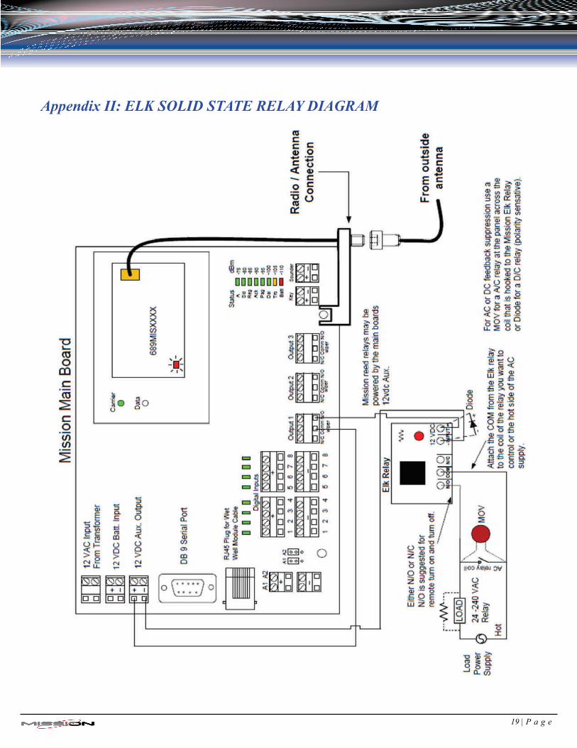
Appendix II: ELK SOLID STATE RELAY DIAGRAM
19 | P a g e
Appendix III: TROUBLE RELAY WIRING DIAGRAM
20 | P a g e
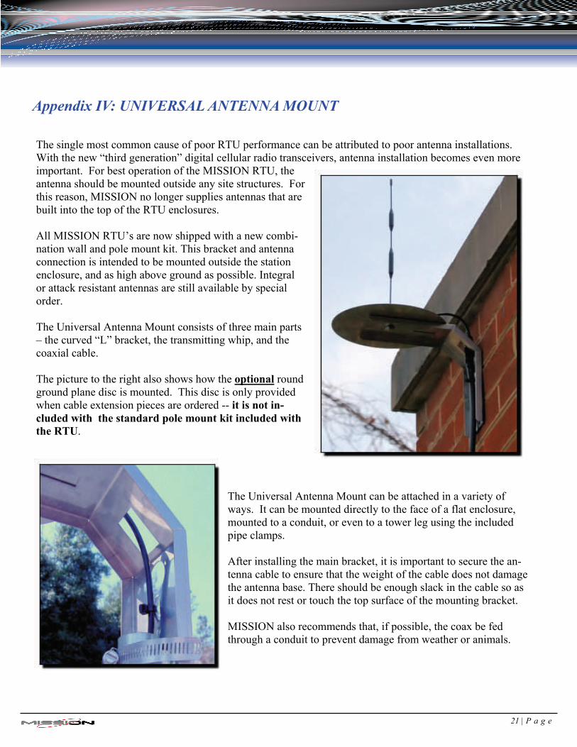
Appendix IV: UNIVERSAL ANTENNA MOUNT The single most common cause of poor RTU performance can be attributed to poor antenna installations. With the new “third generation” digital cellular radio transceivers, antenna installation becomes even more important. For best operation of the MISSION RTU, the antenna should be mounted outside any site structures. For this reason, MISSION no longer supplies antennas that are built into the top of the RTU enclosures. All MISSION RTU’s are now shipped with a new combi-nation wall and pole mount kit. This bracket and antenna connection is intended to be mounted outside the station enclosure, and as high above ground as possible. Integral or attack resistant antennas are still available by special order. The Universal Antenna Mount consists of three main parts – the curved “L” bracket, the transmitting whip, and the coaxial cable. The picture to the right also shows how the optional round ground plane disc is mounted. This disc is only provided when cable extension pieces are ordered -- it is not in-cluded with the standard pole mount kit included with the RTU.
The Universal Antenna Mount can be attached in a variety of ways. It can be mounted directly to the face of a flat enclosure, mounted to a conduit, or even to a tower leg using the included pipe clamps. After installing the main bracket, it is important to secure the an-tenna cable to ensure that the weight of the cable does not damage the antenna base. There should be enough slack in the cable so as it does not rest or touch the top surface of the mounting bracket. MISSION also recommends that, if possible, the coax be fed through a conduit to prevent damage from weather or animals.
21 | P a g e
Appendix IV: UNIVERSAL ANTENNA MOUNT (cont’d)
Here are some additional antennal installation “Do’s” and “Don’ts” to make sure your site’s antenna instal-lation a success.
DO mount the antenna as high as possible, preferably above the roof. DO mount the antenna above all metal surfaces close to the installation.
DO run an 8 to 10 gauge ground wire to the MISSION RTU enclosure (back plate for NEMA-4) to ensure that the antenna base and RTU have the same ground potential.
DO wrap excess coax in loose circles of 8-12 inches in diameter. Pinching or tight bends in the coax can restrict the radio signal path in much the same way water flow is restricted through a tight bend in a pipe. DO NOT over tighten the nut on the antenna base. Finger tight plus 1/4 turn only. DO NOT mount the antenna inside a metal control cabinet! Although fiberglass cabinets may only attenuate the signal a small amount, MISSION always recommends the antenna be mounted outside and above all surfaces.
DO NOT mount the antenna on the side of a metal cabinet. Metal surfaces will reflect the radio sig-nal, preventing it from traveling in all directions.
DO NOT mount the antenna underground, in a dry well, or inside a “canned” lift station.
DO NOT mount the antenna horizontally (sideways) or bend the antenna whip.
DO NOT cut, lengthen, or shorten the coaxial cable. MISSION can supply antenna extension cables and connectors up to 50 feet. For lengths above this limit, another RTU mounting location should be made.
Follow these simple rules and the MISSION RTU will have the best signal possible.
22 | P a g e

INSTALLATION NOTES:
23 | P a g e

INSTALLATION NOTES:
24 | P a g e

PAGE LEFT BLANK INTENTIONALLY
25 | P a g e

PAGE LEFT BLANK INTENTIONALLY
26 | P a g e

3060C Business Park Drive, Norcross, GA 30039 678.969.0021 678.969.0541 (fax)
www.123mc.com [email protected] [email protected]
Literature Code: #I1-1- 09