Embed Size (px)
Citation preview

ME6402 Manufacturing Technology -II
SCE 57 Department of Mechanical Engineering
M09 Coolant OFF
M19 Spindle orientation
M28 Return to origin
M29 Rigid tap
M30 End of program (Reset)
M41 Low gear select
M42 High gear select
M94 Cancel mirrorimage
M95 Mirrorimage of X axis
M96 Mirrorimage of Y axis
M98 Subprogram call
M99 End of subprogram
5.4 Manual Part Programming
Lathe
G02 G03 G Code Circular Interpolation
G02 G Code Clock wise Circular Interpolation.
G03 G Code Counter Clock wise Circular Interpolation.
There are multiple articles/cnc program examples about G code circular interpolation, here isthe list of few articles so that cnc machinists can easily navigate through different cncprogramming articles.
G02 G03 G Code Example CNC Programs (G code Arc Examples)o CNC Circular Interpolation Tutorial G02 G03o Fanuc CNC Lathe Programming Exampleo CNC Programming Example G Code G02 Circular Interpolation Clockwiseo Fanuc G20 Measuring in Inches with CNC Program Exampleo CNC Arc Programming Exerciseo CNC Programming for Beginners a CNC Programming Exampleo CNC Lathe Programming Example
Here is a new CNC programming examples which shows the use of G02 G03 G codecircular interpolation.
G02 G03 G Code Example Program

ME6402 Manufacturing Technology -II
SCE 58 Department of Mechanical Engineering
G02 G03 G Code Circular Interpolation Example Program
N20 G50 S2000 T0300G96 S200 M03G42 G00 X35.0 Z5.0 T0303 M08G01 Z-20.0 F0.2G02 X67.0 Z-36.0 R16.0G01 X68.0 :G03 X100.0 Z-52.0 R16.0G01 Z-82.0G40 G00 X200.0 Z200.0 M09 T0300M30
G Code G02 G03 I & K Example Program
G02 G03 G Code Circular Interpolation can be programmed in two ways,
G02 X... Z... R...G02 X... Z... I... K...
The below is the same cnc program but this version uses I & K with G02 G03 G code.
N20 G50 S2000 T0300G96 S200 M03G42 G00 X35.0 Z5.0 T0303 M08G01 Z-20.0 F0.2G02 X67.0 Z-36.0 I16.0 K0G01 X68.0 :G03 X100.0 Z-52.0 I0 K-16.0G01 Z-82.0G40 G00 X200.0 Z200.0 M09 T0300

ME6402 Manufacturing Technology -II
SCE 59 Department of Mechanical Engineering
M30
G20 Turning Cycle Format for Straight TurningG20 X… Z… F…
or
G20 U… W… F…
X – Diameter to be cut (absolute).Z – End point in z-axis (absolute).F – Feed-rate.U – Diameter to be cut (incremental).W – End point in z-axis (incremental).
G20 Turning Cycle – CNC Lathe Fanuc 21 TBG20 Turning Cycle Format for Taper TurningG20 X… Z… R… F…
or
G20 U… W… R… F…
X – Diameter to be cut (absolute).Z – End point in z-axis (absolute).R – Incremental taper dimension in X with direction (+/-)F – Feed-rate.U – Diameter to be cut (incremental).W – End point in z-axis (incremental).
As cnc machinists can use X or U value for the contour value, same way Z or W can be usedor you can even mix both absolute (X, Z) and incremental (U, W) values.
G20 Turning Cycle Example CNC Program Code

ME6402 Manufacturing Technology -II
SCE 60 Department of Mechanical Engineering
G96 S200 M03G00 X56.0 Z2.0G20 X51.0 W-20.0 F0.25X46.0X41.0X36.0X31.0X30.0G00 X100 Z100M30
CNC Program Code Explanation
As you can see in the above cnc program code,Tool is at X56 Z2 point,First cut is made at X51 and tool travels W-20 in Z-axis.Second cut is made at X46Third cut is made at X41…Last cut is made at X30
G20 Turning Cycle Function
As if you study the above cnc program code you will notice that,1 – with G20 both absolute (X51.0) and incremental (W-20.0) values are used to make cuts.2 – If above code also shows a very powerful functionality of G20 turning cycle which is thata cnc machinist can control depth-of-cut of every pass of G20 turning cycle which isimpossible to achieve with other Turning Canned Cycle like G71 Rough Turning Cycle.So you will notice first five-cuts are of 5mm deep but the last one is just 1mm deep.
Cancellation of G20 Turning Cycle
G20 turning cycle is a modal G-code.“Modal” G-code meaning that they stay in effect until they are cancelled or replaced by acontradictory G code.It means G20 turning cycle remains active until another motion command is given like G00,G01 etc. As in above cnc program example G20 G code is cancelled with G00 G code.
Milling
ProgrammingG72.1 P... L... X... Y... R...
ParametersParameter Description
P Subprogram number
L Number of times the operation is repeated
X Center of rotation on the X axis
ME6402 Manufacturing Technology -II
SCE 61 Department of Mechanical Engineering
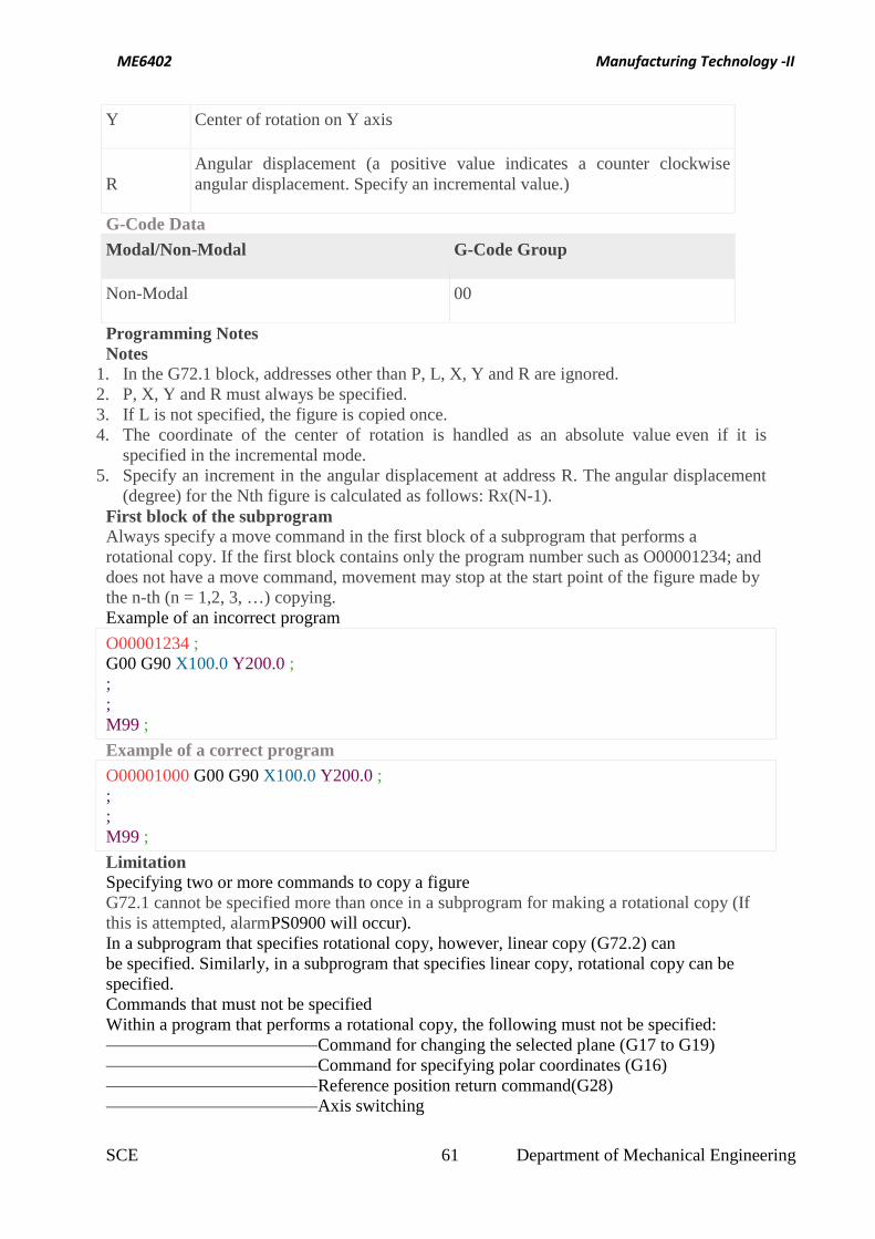
Y Center of rotation on Y axis
RAngular displacement (a positive value indicates a counter clockwiseangular displacement. Specify an incremental value.)
G-Code DataModal/Non-Modal G-Code Group
Non-Modal 00
Programming NotesNotes
1. In the G72.1 block, addresses other than P, L, X, Y and R are ignored.2. P, X, Y and R must always be specified.3. If L is not specified, the figure is copied once.4. The coordinate of the center of rotation is handled as an absolute value even if it is
specified in the incremental mode.5. Specify an increment in the angular displacement at address R. The angular displacement
(degree) for the Nth figure is calculated as follows: Rx(N-1).First block of the subprogramAlways specify a move command in the first block of a subprogram that performs arotational copy. If the first block contains only the program number such as O00001234; anddoes not have a move command, movement may stop at the start point of the figure made bythe n-th (n = 1,2, 3, …) copying.Example of an incorrect program
O00001234 ;G00 G90 X100.0 Y200.0 ;;;M99 ;
Example of a correct programO00001000 G00 G90 X100.0 Y200.0 ;;;M99 ;
LimitationSpecifying two or more commands to copy a figureG72.1 cannot be specified more than once in a subprogram for making a rotational copy (Ifthis is attempted, alarmPS0900 will occur).In a subprogram that specifies rotational copy, however, linear copy (G72.2) canbe specified. Similarly, in a subprogram that specifies linear copy, rotational copy can bespecified.Commands that must not be specifiedWithin a program that performs a rotational copy, the following must not be specified:
Command for changing the selected plane (G17 to G19)Command for specifying polar coordinates (G16)Reference position return command(G28)Axis switching

ME6402 Manufacturing Technology -II
SCE 62 Department of Mechanical Engineering
Coordinate system rotation (G68)scaling (G51)programmable mirror image (G51.1)
The command for rotational copying can be specified after a command for coordinate systemrotation, scaling, or programmable mirror image is executed.Single blockSingle-block stops are not performed in a block with G721.1 or G72.2.
G72.1 Programming Example
Main program
O1000 ;N10 G90 G00 X80. Y100. ; (P1)N20 Y50. ; (P2)N30 G01 G17 G42 X43.301 Y25. D01 F100 ;(P3)N40 G72.1 P1100 L3 X0 Y0 R120. ;N50 G90 G40 G01 X80. Y50. ; (P2)N60 G00 X80. Y100. ; (P1)N70 M30 ;