Embed Size (px)
Citation preview

R12-17...L120-11Model: M05
en Assembly and Operating Instructions
Tubular drives with crank handle activation
Important information for:
• Fitters / • Electricians / • Users
Please forward accordingly!
These instructions must be kept safe for future reference.
Becker-Antriebe GmbHFriedrich-Ebert-Straße 2-435764 Sinn/Germanywww.becker-antriebe.com
2010 300 231 0g 06/11/2018

Table of contents
General ............................................................................................................................................................................... 3Warranty ............................................................................................................................................................................. 3Safety instructions ............................................................................................................................................................... 4
Instructions for the user................................................................................................................................................... 4Instructions for installation and commissioning.................................................................................................................. 4
Intended use ....................................................................................................................................................................... 6Drive version with angled plug ............................................................................................................................................... 6Installation........................................................................................................................................................................... 8
Assembling the drive ....................................................................................................................................................... 8Drive adapter safety catch ............................................................................................................................................... 8
Assembling the drive adapter with safety catch on the drive shaft................................................................................... 8Disassembling the drive adapter with safety catch on the drive shaft .............................................................................. 9Assembling and disassembling the drive adapter with separate drive adapter safety catch............................................... 9Assembling and disassembling the drive adapter with screw connection ........................................................................ 9
Mounting the drive in the tube .......................................................................................................................................... 9Setting the limit positions.................................................................................................................................................... 12Using the crank handle ....................................................................................................................................................... 13Information for the electrician ............................................................................................................................................. 13Disposal ............................................................................................................................................................................ 13Maintenance ..................................................................................................................................................................... 13Technical data dia. 45 ........................................................................................................................................................ 14Technical data dia. 58 ........................................................................................................................................................ 14What to do if...?.................................................................................................................................................................. 15Sample wiring diagrams ..................................................................................................................................................... 16Declaration of conformity ................................................................................................................................................... 18
2
GeneralThese tubular drives are high-quality products with the following features:
• For use with roller shutters
• For use with sunblinds
• For use with doors
• Convenient manual control in the event of power failure
• Easy limit switch setting on the drive
• Compatible with all of the drive manufacturer's control units for roller shutters and sunblinds
Please observe these Assembly and Operating Instructions when installing and setting up the equipment.The date of manufacture comes from the first four digits of the serial number.The numbers 1 and 2 indicate the year and the numbers 3 and 4 indicate the calendar week.Example: 24th calendar week in 2012
Ser. No.: 1224XXXXX
Explanation of pictograms
CAUTION CAUTION indicates a hazardous situation which, if not avoided, couldresult in injury.
ATTENTION ATTENTION indicates measures that must be taken to avoid damage toproperty.
Denotes user tips and other useful information.
WarrantyStructural modifications and incorrect installation which are not in accordance with these and our other instructions can result inserious injuries, e.g., crushing of limbs. Therefore, structural modifications may only be carried out with our prior approval andstrictly in accordance with our instructions, particularly the information contained in these Assembly and Operating Instructions.Any further processing of the products which does not comply with their intended use is not permitted.The end product manufacturer and fitter have to ensure that all the relevant current statutory, official and, in particular, EMC regu-lations are adhered to during utilisation of our products, especially with regard to end product manufacture, installation and cus-tomer advice.
3

Safety instructionsThe following safety instructions and warnings are intended to avert hazards and to prevent property damage and personal injury.
Instructions for the user
General information• The drive must be disconnected from its power source during cleaning and maintenance and when re-
placing parts.
• All work, including maintenance and cleaning, on electrical installations as well as other system partsmust always be performed by trained technicians, in particular qualified electricians.
• Children from the age of 8 years and persons with reduced physical, sensory or mental capabilities orlack of experience and/or knowledge may use these devices, provided they are supervised or havebeen instructed in the safe use of the device, and have understood the hazards involved. Children mustnot play with the device.
• Systems have to be checked regularly by authorised specialists for wear and damage.
• Always put damaged systems out of operation immediately until they are repaired by an authorisedspecialist.
• Do not operate equipment if people or objects are within the danger zone.
• Observe the danger zone of the equipment during operation.
• Ensure that there is adequate clearance (at least 40 cm) between moving parts and adjacent objects.
CautionSafety instructions for avoiding serious injuries.• Crushing or shearing points must be avoided or protected.
Instructions for installation and commissioning
General information• Observe the safety instructions in EN 60335-2-97. Please note that this list of safety instructions is not
exhaustive, since it would be impossible for the standard to include all sources of danger. For example,the design of the operated product, the way the drive works in the situation it is installed in or even theway the end product is mounted in the end user’s place of use cannot be taken into consideration bythe drive manufacturer. If any questions or uncertainties regarding the safety instructions contained in the standard arise,please contact the manufacturer of the part or end product in question.
• All applicable standards and regulations for electrical installation must be complied with.
• All work, including maintenance and cleaning, on electrical installations as well as other system partsmust always be performed by trained technicians, in particular qualified electricians.
• Only use spare parts, tools and accessory devices which have been approved by the drive manufac-turer. Unapproved third-party products or modifications to the system and its accessories represent a risk toyour safety and the safety of others. This means that the use of unapproved third-party products, ormodifications which have not been agreed with or approved by us, are prohibited. We do not accept li-ability for damage or injury arising from such actions.
• Position switch with OFF presetting within sight of the driven product, but away from moving parts, at aheight of over 1.5 m. This must not be publicly accessible.
• Permanently mounted control devices must be positioned where they can be seen.
• Rated torque and duty cycle must be suitable for the requirements of the driven product. Technical data - rated torque and service life can be found on the type plate of the tubular drive.
4
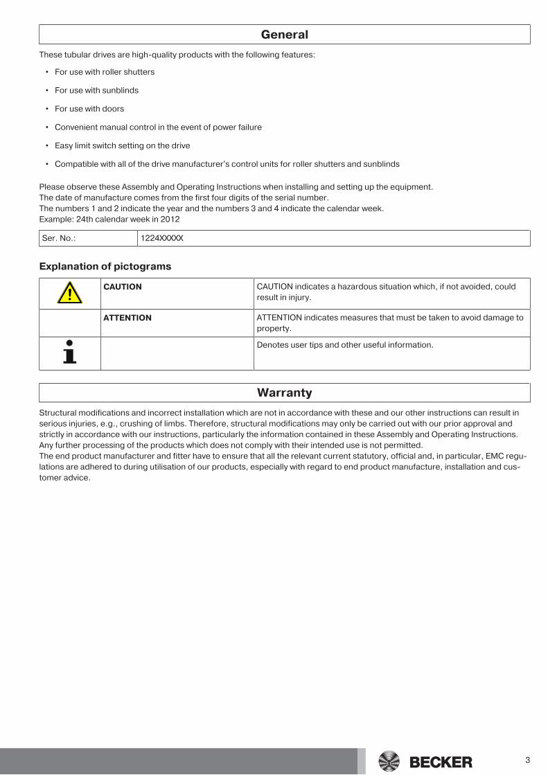
• Hazardous moving parts of the drive must be installed at a height of over 2.5 m above floor level or anyother surface from which the drive can be accessed.
• To ensure safe operation of the system after commissioning, the limit positions must be correctly set/programmed in.
• Drives with a H05VV-F connecting cable may only be used indoors.
• Drives with a H05RR-F, S05RN-F or 05RN-F connecting cable may be used both indoors and outdoors.
• To connect the drive to the driven part, solely mechanical accessory components made by the drivemanufacturer from the current product catalogue may be used. The components must be installed inaccordance with the manufacturer's instructions.
• If the drive is used for shading solutions in a specially marked area (e.g., escape routes, hazard zones,safety areas), compliance with all applicable regulations and standards must be ensured.
CautionSafety instructions for avoiding serious injuries.• When electrical or electronic equipment and units are operated, certain components,
e.g., the power supply unit, are live. Physical injuries or damage to property can result inthe event of unauthorised interventions or failure to heed warnings.
• Be careful when touching the tubular drive, as it heats up during operation for technolo-gical reasons.
• Before installation, shut down all lines and control devices that are not essential for op-eration.
• Crushing or shearing points must be avoided or protected.
• When installing the drive, all-pole disconnection from the mains with a contact gap of atleast 3 mm per pole must be provided (EN 60335).
• If the mains connecting cable is damaged, it may only be replaced by the manufacturer.
• When using doors, particularly the standard EN 12453 must be observed.
AttentionSafety instructions for avoiding property damage.• Ensure that there is adequate clearance between moving parts and adjacent objects.
• The drive must not be carried by the mains connecting cable.
• All latching connections and fastening screws on the brackets must be checked to en-sure that they are secure.
• Ensure that nothing rubs against the tubular drive, such as shading solution attach-ments, screws, etc.
5

Intended useThe type of tubular drive described in these instructions is intended solely for the operation of roller shutters, roller doors and sunprotection systems. The crank handle is intended to be used for convenient manual operation only in the event of a power fail-ure. Continuous operation or use of tools (e.g. drilling machines for activation of the crank handle) is prohibited as, after a certainamount of time, this leads to loss of manual function and with it the tubular drive.This type of tubular drive is designed for use in single systems (one drive per barrel).The tubular drive must not be used in potentially explosive areas.The connecting cable is not suitable for transporting the drive. Always carry the drive by the housing tube.Other applications, uses and modifications are not permitted in order to protect the safety of the users and others, since these ac-tions can impair the system’s safety and carry the risk of personal injury and property damage. The drive manufacturer does notaccept liability for damages or injury arising from such actions.Always observe the information in these instructions when operating or repairing the system. The drive manufacturer does not ac-cept liability for damage or injury resulting from improper usage.
Drive version with angled plug
Assembling the plug-in connecting cable for tubular drives with angled plugInsert the dead connecting cable into the angled plug until the locating lug clicks into place in the angled plug. If necessary, use asuitable flathead screwdriver to assist with insertion. Set the screwdriver into one of the two grooves on the plug-in connectingcable provided for this purpose.Check that the cable is properly engaged.
1
1 = locating lug
6
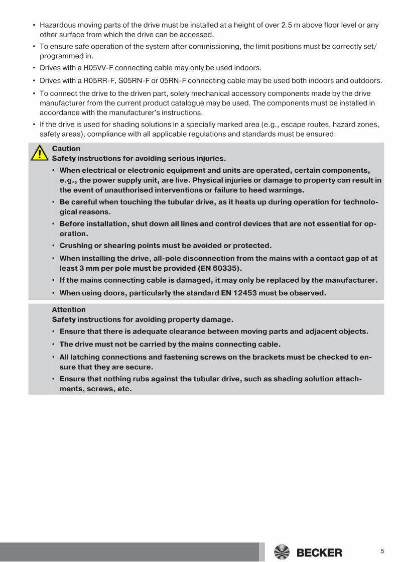
Disassembling the plug-in connecting cable for tubular drives with angled plug
CautionPrior to disassembly, the power supply to the connecting cable must be disconnected.
Insert a suitable flathead screwdriver right into the recess of the locating latch, so that the latch releases the locating lug from theplug.
Now you can pull out the connecting cable along with the flathead screwdriver.
A
A = locating latch
7
Installation
Assembling the drive
AttentionTo connect the drive to the driven part, solely mechanical accessory components made bythe drive manufacturer from the current product catalogue may be used.
Prior to mounting, the fitter must ensure that the masonry and the system being motorised are sufficiently robust (drive torque plusweight of the shading solution).
CautionElectrical connections may only be carried out by a qualified electrician. Prior to assembly,the power supply must be disconnected and secured. Please give the enclosed connectioninformation to the responsible electrical contractor.
AttentionThe fastening elements (wall bracket) must be aligned and fixed so that tensions cannotoccur when screwing the crank handle housing.
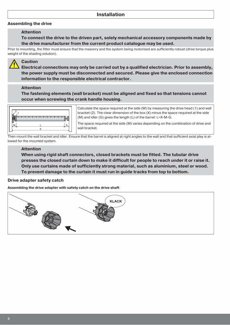
Calculate the space required at the side (M) by measuring the drive head (1) and wallbracket (2). The clear dimension of the box (X) minus the space required at the side(M) and idler (G) gives the length (L) of the barrel: L=X-M-G.
The space required at the side (M) varies depending on the combination of drive andwall bracket.
Then mount the wall bracket and idler. Ensure that the barrel is aligned at right angles to the wall and that sufficient axial play is al-lowed for the mounted system.
AttentionWhen using rigid shaft connectors, closed brackets must be fitted. The tubular drivepresses the closed curtain down to make it difficult for people to reach under it or raise it.Only use curtains made of sufficiently strong material, such as aluminium, steel or wood.To prevent damage to the curtain it must run in guide tracks from top to bottom.
Drive adapter safety catch
Assembling the drive adapter with safety catch on the drive shaft
8

Disassembling the drive adapter with safety catch on the drive shaft
Disassembly with disassembly tool, Item no. 4930 300 606 0
Disassembly with long nose pliers
2.
1.
Assembling and disassembling the drive adapter with separate drive adapter safety catch
Assembling and disassembling the drive adapter with screw connection
Mounting the drive in the tube
For profile tubes:
In the case of some drive adapters, tolerances of the groove widths in different bar-rels can be offset by rotating the drive adapter into a different groove recess. Thesegroove recesses have different sizes and allow the drive to fit exactly.
9
Y
X
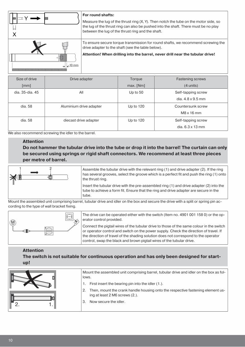
For round shafts:
Measure the lug of the thrust ring (X, Y). Then notch the tube on the motor side, sothe lug of the thrust ring can also be pushed into the shaft. There must be no playbetween the lug of the thrust ring and the shaft.
-10 mm
To ensure secure torque transmission for round shafts, we recommend screwing thedrive adapter to the shaft (see the table below).
Attention! When drilling into the barrel, never drill near the tubular drive!
Size of drive
[mm]
Drive adapter Torque
max. [Nm]
Fastening screws
(4 units)
dia. 35-dia. 45 All Up to 50 Self-tapping screw
dia. 4.8 x 9.5 mm
dia. 58 Aluminium drive adapter Up to 120 Countersunk screw
M8 x 16 mm
dia. 58 diecast drive adapter Up to 120 Self-tapping screw
dia. 6.3 x 13 mm
We also recommend screwing the idler to the barrel.
AttentionDo not hammer the tubular drive into the tube or drop it into the barrel! The curtain can onlybe secured using springs or rigid shaft connectors. We recommend at least three piecesper metre of barrel.
Assemble the tubular drive with the relevant ring (1) and drive adapter (2). If the ringhas several grooves, select the groove which is a perfect fit and push the ring (1) ontothe thrust ring.
Insert the tubular drive with the pre-assembled ring (1) and drive adapter (2) into thetube to achieve a form fit. Ensure that the ring and drive adapter are secure in thetube.
Mount the assembled unit comprising barrel, tubular drive and idler on the box and secure the drive with a split or spring pin ac-cording to the type of wall bracket fixing.
The drive can be operated either with the switch (Item no. 4901 001 158 0) or the op-erator control provided.
Connect the pigtail wires of the tubular drive to those of the same colour in the switchor operator control and switch on the power supply. Check the direction of travel. Ifthe direction of travel of the shading solution does not correspond to the operatorcontrol, swap the black and brown pigtail wires of the tubular drive.
AttentionThe switch is not suitable for continuous operation and has only been designed for start-up!
Mount the assembled unit comprising barrel, tubular drive and idler on the box as fol-lows.
1. First insert the bearing pin into the idler (1.).
2. Then, mount the crank handle housing onto the respective fastening element us-ing at least 2 M6 screws (2.).
3. Now secure the idler.
10

Lay the connecting cable
Lay the connecting cable up to the tubular drive, and fix The connecting cable andany antennae must not project into the winding chamber. Cover any sharp edges.
11
Setting the limit positions
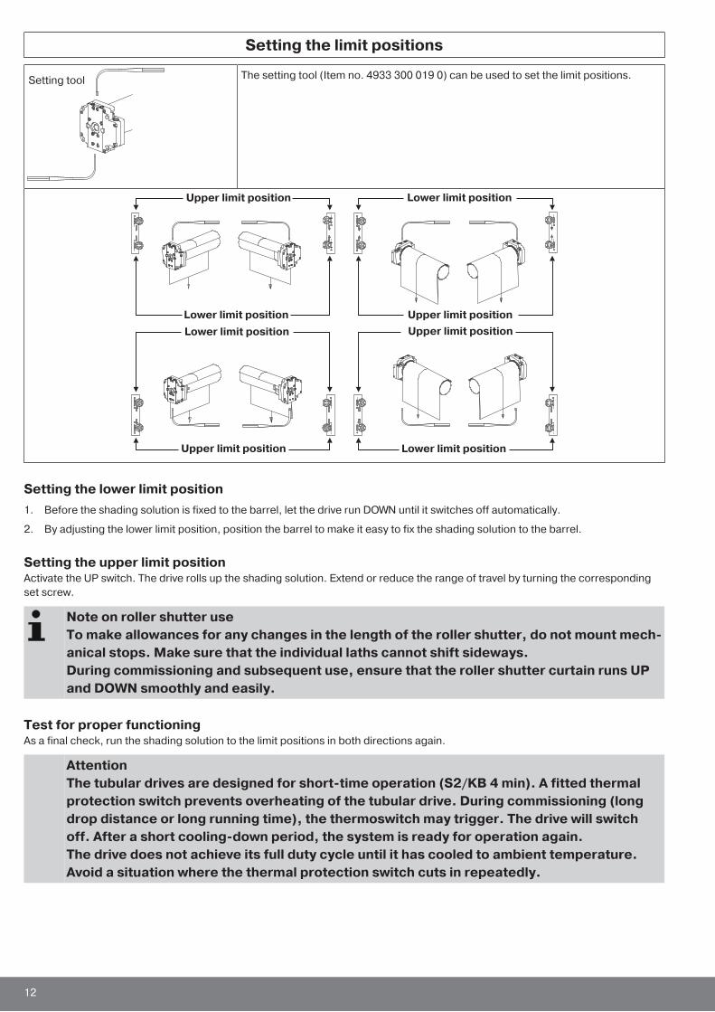
Setting toolThe setting tool (Item no. 4933 300 019 0) can be used to set the limit positions.
Upper limit position
Upper limit position
Upper limit position
Upper limit position
Lower limit position
Lower limit position
Lower limit position
Lower limit position
Setting the lower limit position1. Before the shading solution is fixed to the barrel, let the drive run DOWN until it switches off automatically.
2. By adjusting the lower limit position, position the barrel to make it easy to fix the shading solution to the barrel.
Setting the upper limit positionActivate the UP switch. The drive rolls up the shading solution. Extend or reduce the range of travel by turning the correspondingset screw.
Note on roller shutter useTo make allowances for any changes in the length of the roller shutter, do not mount mech-anical stops. Make sure that the individual laths cannot shift sideways.During commissioning and subsequent use, ensure that the roller shutter curtain runs UPand DOWN smoothly and easily.
Test for proper functioningAs a final check, run the shading solution to the limit positions in both directions again.
AttentionThe tubular drives are designed for short-time operation (S2/KB 4 min). A fitted thermalprotection switch prevents overheating of the tubular drive. During commissioning (longdrop distance or long running time), the thermoswitch may trigger. The drive will switchoff. After a short cooling-down period, the system is ready for operation again.The drive does not achieve its full duty cycle until it has cooled to ambient temperature.Avoid a situation where the thermal protection switch cuts in repeatedly.
12
Using the crank handle
For problem-free assembly, use mechanical and electrical accessories made by the drivemanufacturer which have been tested and which are suitable for use with these drives.
For 7 mm hexagonal tube
and 8 mm square tubeThe crank handle is to be used only in the event of a power failure. It must be ensuredthat the limit positions are not overrun.
Crank handle for closed models
The crank handle for closed models can be used with roller shutters and roller doors,either with or without a roll-up system. The square bar is fixed to the shutter box.Here, it is important to ensure that the bar is mounted parallel to the guide in thecrank handle housing.
Crank handle for open models
These crank handles can be used with awnings, as well as with roller shutters androller doors without roll-up systems. Insert the square bar into the guide in the crankhandle housing and secure axially using a retaining washer or two set screws.
Information for the electricianThe tubular drives with mechanical limit switching must not be connected in parallel. The drive manufacturer offers a range of suit-able controls for the simultaneous control of several drives.Use external conductor L1 to control the up and down direction. Other devices or consumers (lamps, relays, etc.) must not be dir-ectly connected to the drive connecting cables. For this purpose, the drives and additional devices must be decoupled by relaycontrols.When installing the drive, all-pole disconnection from the mains with a contact gap of at least 3 mm per pole must be provided.
AttentionOnly use mechanically or electrically locked switching elements with a marked zero posi-tion! This also applies when drives with electronic and mechanical limit switching are usedin the same system. The changeover time for switching the running direction must be atleast 0.5 s. The switch and control must not execute simultaneous UP and DOWN com-mands. Protect the electrical connections from damp.Once you have finished wiring everything to the control, ALWAYS check the right directionassignment of the drive to the control buttons UP and DOWN, EXTEND and RETRACT.If the drive is to be operated with devices which contain sources of interference, the elec-trician must ensure suitable interference suppression for the relevant devices.
DisposalThis product is made of various materials which must be disposed of properly. Find out about the applicable regulations on recyc-ling or disposal for this product in your country.The packaging material must be disposed of properly.
MaintenanceThese drives are maintenance-free.
13
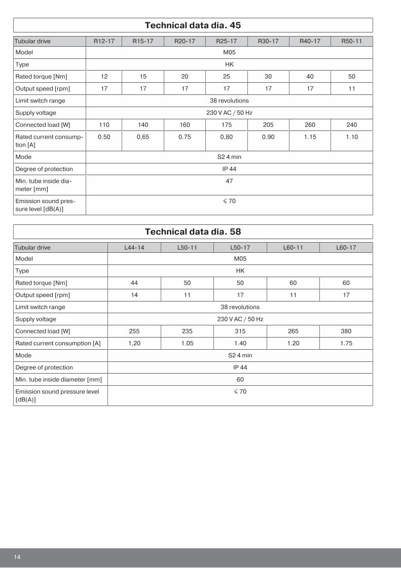
Technical data dia. 45
Tubular drive R12-17 R15-17 R20-17 R25-17 R30-17 R40-17 R50-11
Model M05
Type HK
Rated torque [Nm] 12 15 20 25 30 40 50
Output speed [rpm] 17 17 17 17 17 17 11
Limit switch range 38 revolutions
Supply voltage 230 V AC / 50 Hz
Connected load [W] 110 140 160 175 205 260 240
Rated current consump-tion [A]
0.50 0,65 0.75 0,80 0.90 1.15 1.10
Mode S2 4 min
Degree of protection IP 44
Min. tube inside dia-meter [mm]
47
Emission sound pres-sure level [dB(A)]
≤ 70
Technical data dia. 58
Tubular drive L44-14 L50-11 L50-17 L60-11 L60-17
Model M05
Type HK
Rated torque [Nm] 44 50 50 60 60
Output speed [rpm] 14 11 17 11 17
Limit switch range 38 revolutions
Supply voltage 230 V AC / 50 Hz
Connected load [W] 255 235 315 265 380
Rated current consumption [A] 1,20 1.05 1.40 1.20 1.75
Mode S2 4 min
Degree of protection IP 44
Min. tube inside diameter [mm] 60
Emission sound pressure level[dB(A)]
≤ 70
14
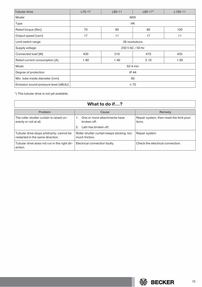
Tubular drive L70-17 L80-11 L80-17* L120-11
Model M05
Type HK
Rated torque [Nm] 70 80 80 120
Output speed [rpm] 17 11 17 11
Limit switch range 38 revolutions
Supply voltage 230 V AC / 50 Hz
Connected load [W] 430 310 470 435
Rated current consumption [A] 1.90 1.40 2.10 1.90
Mode S2 4 min
Degree of protection IP 44
Min. tube inside diameter [mm] 60
Emission sound pressure level [dB(A)] ≤ 70
*) This tubular drive is not yet available.
What to do if...?
Problem Cause Remedy
The roller shutter curtain is raised un-evenly or not at all.
1. One or more attachments havebroken off.
2. Lath has broken off.
Repair system; then reset the limit posi-tions.
Tubular drive stops arbitrarily; cannot berestarted in the same direction.
Roller shutter curtain keeps sticking; toomuch friction.
Repair system
Tubular drive does not run in the right dir-ection.
Electrical connection faulty. Check the electrical connection.
15
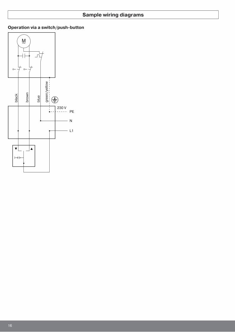
Sample wiring diagrams
Operation via a switch/push-button
bla
ck
PE230 V
N
L1
bro
wn
blu
e
gre
en
/ye
llo
w
16

Central, group and individual control using Centronic UnitControl UC42
Mains 230 V / 50 HzCentral
Group
Individual Individual
230 V / 50 HzCentral cable
(connection to further control units)
230 V / 50 Hz
230 V / 50 Hz
Ele
ctr
on
ics
230 V / 50 Hz
Control unit
17
Declaration of conformity
18

19


![de partido a su piscina… - BINDER · Tipo BGA 160 BGA 215 BGA 275 BGA 320 BGA 430 BGA 550 BGA 600 BGA 1200 Tensión de conexión [VAC] 230 230 230 230 230 230 230 230 Rango de frecuencia](https://img.pdfslide.us/doc/110x75/5c132e8509d3f26c7c8c5e0d/de-partido-a-su-piscina-binder-tipo-bga-160-bga-215-bga-275-bga-320-bga-430.jpg)