Embed Size (px)
Citation preview

_________n~a ~~ AY4 FOR R~Y ADCTION PURPOSES.~UU M -g -
' 4 ma.4-1Form Approved
REPORiILl om NO. 0704.0188PublIc resortig bur'den/ for th~t oliect,¢ l•ll U l"he tome for reviewing instruCtaOn, elteachng eJnttsnq daeta toacev.gathering - meantainang the data4 • :ommenty re cing th burden aettmete or any other asine of that
c olletn of informaetio. including ug DrectorFate lOt formOti Operation, and Reports. 121S Jefferson0eVi Highway. Shte 1204. Arlington. V Reduction Project (0704-0 IN), Washington. DC 20S0.
1. AGENCY USE ONLY (Leave blank) 12. REPORT DATE 1. REPORT TYPE AND DATES COVEREDApr 94 Final 1 Feb 93-30 Sep 93
4. TITLE AND SUBTITLE S. FUNDING NUMBERS
Dynamic Response of Composite Structures DAAHO4-93-G-0052
IL AUTHOR(S)
David Hui (Principal investigator)
7. PERFORMING ORGANIZATION NAME(S) AND ADORISS(EVU1 X8I. PERFORMING ORGANIZATIONREPORT NUMBER
New Orleans, LA 70148 l
S. SPONSORING /MONITORING AGENCY NAME(S) AND A ES 10. SPONSORING/ MONITORING
U. S. Army Research Office AGENCY REPORT NUMBER
P. 0. Box 12211 ARO 30904.1-EG-CFResearch Triangle Park, NC 27709-2211
11. SUPPLEMENTARY NOTES
The view, opinions and/or findings contained in this report are those of theauthor(s) and should not be construed as an official Department of the Armyposition, policy, or decision, unless so designated by other documentation.
124. DISTRIUTION i AVAILABLITY STATEMENT 1Zb. DISTRIBUTION CODE
Approved for public release; distribution unlimited.
13. ABSTRACT (Maximum 200 words)
The purpose of the workshop was to:
(i) assess the state of the art in the modeling and analysis of modem composite structuresthat are relevant to the Army's need to improve the design-and operation of landvehicles, helicopters, weapon systems, etc.
(ii) identify new opportunities for relevant research.Re special areas or interest were crash worthiness of composite structures,composite helicopter rotor blade dynamics, stability and control, smart compositestructures, etc.
The workshop contained six keynote and distinguished lectures and 34 lecturesfor a total of 40 paper presentations. The regular sessions include (i) Vibrationof Composite Structures (ii) Smart Structures (iii) Impact of Composite Structures(iv) Damage and Failure (v) Design of Composite Structures (vi) StructuralMechanics.
14. SUBJECT TERMS 1S. NUMBER OF PAGES
Dynamic Responses, Composite Structures, Land Vehicles,Helicopters, Weapons Systems, Workshop, Structural Mechanics I.PRICE CODE
17. SECURITY CLASSIFICATION 18. SECURITY CLASSIFICATION 1. SECURITY CLASSIFICATION 20. LIMITATION Of ABSTRACT
OF REPORT OF THIS PAGE OF ABSTRACT
UNCLASSIFIED UNCLASSIFIED UNCLASSIFIED ULNSN 7540-01-280-5500 Standard Form 298 (Rev. 2-89)
Presicribed by ANSI Std ,39-I1?W*1-0a
A" 36 16- I II I i
Army Research Office Workshop on:
Dynamic Response of CompositeStructures
Wesdn Hoel, New Orleans, LAAugust 30, 31, Sept 1, 1993.
David HidARO wodmbop bamaknnUniversity of New Odeans
DqVt of Me ical gergNew Orleans, LA 70148
Gary AndersonARO workshop monitor
US Army Researc offRe ScTrianles Dav.
NC 27709-2221 ,- 94-21116
1) Ti C 177r " .....
V rw-
FOREWORD
The Army Research Office is pleased to sponsor the workshop, "DynamicReiponse of Composite Structures" to be held in New Orleans, August 30- September 1,1993. The purpose of the workshop is to:
(i) assess the state of the art in the modeling and analysis of modem composite structuresthat are relevant to the Army's need to improve the design-and operation of landvehicles, helicopters, weapon systems, etc.
(ii) identify new opportunities for relevant research.
The special areas of interest are crash worthiness of composite structures, compositehelicopter rotor blade dynamics, stability and control, smart composite structures, etc.Other area of composite structural research are welcomed and the authors are encouraged toshow the relevance of their work to the U.S. Army.
The workshop contains six keynote and distinguished lectures and 34 lectures for atotal of 40 paper presentations. The regular sessions include (i) Vibration of CompositeStructures (ii) Smart Structures (iii) Impact of Composite Structures (iv) Damage andFailure (v) Design of Composite Structures (vi) Structural Mechanics. We are pleased withthe many outstanding presentations at this ARO workshop and would like to acknowledgethe financial and moral support of the Army Research Office. Thanks are due to thecontributions from the authors, the reviewers and the support and encouragement of Dr.John Crisp, Dean of Engineering, University of New Orleans.
David HuiARO workshop chairman
University of New Orleans
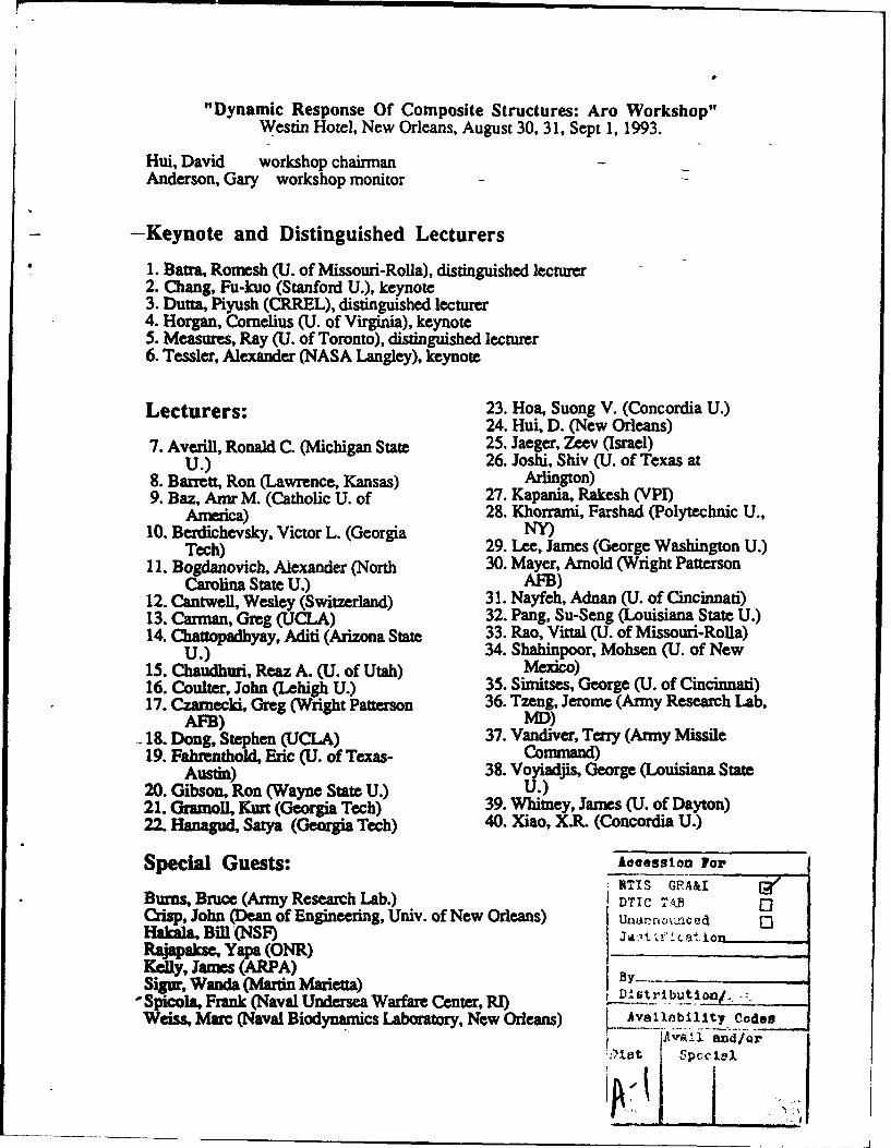
"Dynamic Response Of Composite Structures: Aro Workshop"Westin Hotel, New Orleans, August 30, 31, Sept 1, 1993.
Hui, David workshop chairmanAnderson, Gary workshop monitor
- -Keynote and Distinguished Lecturers
I. Batra, Romesh (U. of Missouri-Rolla), distinguished lecturer2. Chang, Fu-kuo (Stanford U.), keynote3. Dutra, Piyush (CRREL), distinguished lecturer4. Horgan, Cornelius (U. of Virginia), keynote5. Measures, Ray (U. of Toronto), distinguished lecturer6. Tessler, Alexander (NASA Langley), keynote
Lecturers: 23. Hoa, Suong V. (Concordia U.)24. Hui, D. (New Orleans)
7. Averill, Ronald C. (Michigan State 25. Jaeger, Zeev (Israel)U.) 26. Joshi, Shiv (U. of Texas at
8. Barrett, Ron (Lawrence, Kansas) Arlington)9. Baz, Amr M. (Catholic U. of 27. Kapania, Rakesh (VPI)
America) 28. Khorrami, Farshad (Polytechnic U.,10. Berdichevsky, Victor L. (Georgia NY)
Tech) 29. Lee, James (George Washington U.)11. Bogdanovich, Alexander (North 30. Mayer, Arnold (Wright Patterson
Carolina State U.) AFB)12. Cantwell, Wesley (Switzerland) 31. Nayfeh, Adnan (U. of Cincinnati)13. Carman, Greg (UCiLA) 32. Pang, Su-Seng (Louisiana State U.)
14. Chanopadhyay, Aditi (Arizona State 33. Rao, Vittal (U. of Missouri-Rolla)U.) 34. Shahinpoor, Mohsen (U. of New
15. Chaudhuri, Reaz A. (U. of Utah) Mexico)16. Coulter, John (Lehigh U.) 35. Simitses, George (U. of Cincinnati)17. Czarnecki, Greg (Wright Patterson 36. Tzeng, Jerome (Army Research Lab,
AFB) MD)18. Dong, Stephen (UCLA) 37. Vandiver, Terry (Army Missile19. Fahrenthold, Eric (U. of Texas- Command)
Austin) 38. Voyiadjis, George (Louisiana State20. Gibson, Ron (Wayne State U.) U.)21. Gramoil, Kurt (Georgia Tech) 39. Whitney, James (U. of Dayton)22. Hanagud, Satya (Georgia Tech) 40. Xiao, X.R. (Concordia U.)
Special Guests: Aacession ForNTIS RA UI call
Burs, Bruce (Army Research Lab.) DTIC GRA& 0]Ci•, John (Dean of Engineering, Univ. of New Orleans) Una.nou•.ced 0Hakala, Bill (NSF)Rajapaksc, Yapa (ONR)Kelly, James (ARPA) _
Sigur, Wanda Martin Marietta) Distibti"Spicola, Frank (Naval Undersea Warfare Center, RI)Weiss, Marc (Naval Biodynamics Laboratory, New Orleans) Avsilobility Codoes
Avail and/or'is~~tt sp•cclel
rS
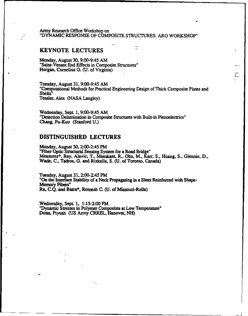
Army Research Office Workshop on"DYNAMIC RESPONSE OF COMPOSITE STRUCTURES: ARO WORKSHOP"
KEYNOTE LECTURES
Monday, August 30,9:00-9:45 AM"Saint-Venant End Effects in Composite Structures"Horgan, Cornelius 0. (U. of Virginia)
Tuesday, August 31, 9-00-9:45 AM"Computational Methods for Practical Engineering Design of Thick Composite Plates andShells"Tessler, Alex (NASA Langley)
Wednesday, Sept. 1, 9:00-9:45 AM"Detection Delamination in Composite Structures with Built-in Piezoelectrics"Chang, Fu-Kuo (Stanford U.)
DISTINGUISHED LECTURES
Monday, August 30, 2:00-2:45 PM"Fiber Optic Structural Sensing System for a Road Bridge"Measures*, Ray, Alavic, T., Maaskant, R., Ohn, M., Karr, S., Huang, S., Glennie, D.,Wade, C., Tadros, G. and Rizkalla, S. (U. of Toronto, Canada)
Tuesday, August 31, 2:00-2:45 PM"On the Interface Stability of a Neck Propagating in a Sheet Reinforced with Shape-Memory Fibers"Ru, C.Q. and Batra*, Rotnesh C. (U. of Missouri-Rolla)
-Wednesday, Sept. 1, 1:15-2:00 PM"Dynamic Stresses in Polymer Composites at Low Temperature"Dutta, Piyush (US Army CRREL, Hanover, NH)
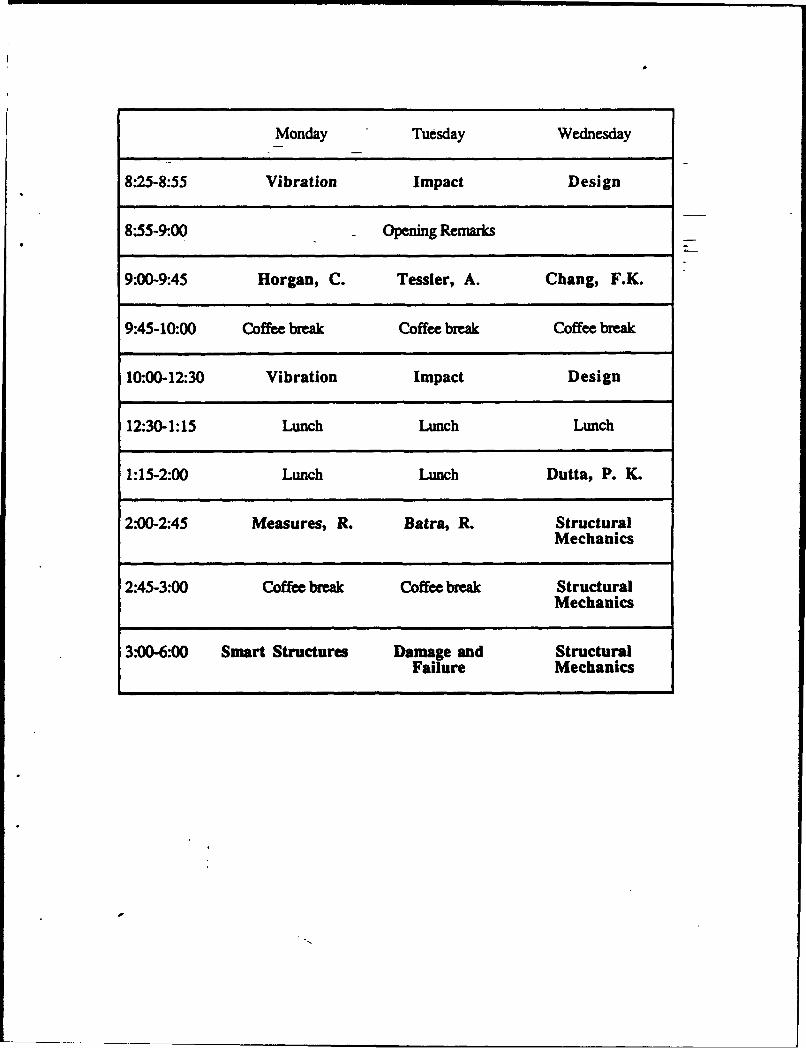
Monday Tuesday Wednesday
8"25-8:55 Vibration Impact Design
8:55-9:00 Opening Remarks
9-00-9:45 Horgan, C. Tessler, A. Chang, F.K.
9:45-10:00 Coffee break Coffee break Coffee break
10:00-12:30 Vibration Impact Design
12:30-1:15 Lunch Lunch Lunch
1:15-2:00 Lunch Lunch Dutta, P. K.
2-00-2:45 Measures, R. Batra, R. StructuralMechanics
2:45-3:00 Coffee break Coffee break StructuralMechanics
3:00-6:00 Smart Structures Damage and StructuralFailure Mechanics
Monday morning, August 30, 8:25-8:55 AMand 10:00 AM-12:30 PM
(last name marked with * indicates presenter)
VIBRATION OF COMPOSITE STRUCTURESChair: Rakesh Kapania (VPl)co-chair Shiv Joshi (U. Texas-Arlington)
"Vibration Analysis of Finite Thin Laminated Doubly-Curved Panels"Chaudhuri, Reaz A. (U. of Utah)
"The Effect of Width on the Free Vibration of Anisotropic Laminated Beams"Whitney, James M. (U. of Dayton)
"High-Frequency Composite Beam Dynamics"Atilgan, A.R., Berdichevsky*, Victor L., CesnikC.E.S., Hodges, D.H. and Sutyrin,V.G. (Georgia Tech)
"Natural Vibrations and Waves in Pretwisted Rods"Onipede, 0., Dong*, Stanley B. and Kosmatka, J.B. (UCLA)
"Vibration Damping Characteristics of Thick Composite Structures"Hwang, S.J. and Gibson*, Ron F. (Wayne State U.)
"Analytical Modeling of Electro-Rheological Material Based Adaptive Beams"Yalcintas, M. and Coulter*, John (Lehigh U.)
Monday afternoon, August 30, 3:OOPM-6:00 PM
SMART STRUCTURESChair. Greg Carman (UCLA)co-chair: Ray Measures (U. of Toronto)
"Optimal Vibration Control of Ntinol-Reinforced Composites"Baz*, Amr and Ro, J. (Catholic U. of America)
"An Innovative Technique for Monitoring Damage Evolution in Composite Materials withFiber Optic Sensors"Cantian, Greg (UCLA)
"Delamination Dynamics and Active Control of Delaminations"Hanagud*, S., Nagesh Babu, G.L. and Luo, H. (Georgia Tech.)
"Control Designs for Smart Structures and Their E Validation"Khorrami, F. (Polytechnic U., NY)
"Optimal Control of Infinite Order Composite Structural Systems Using Distributed PVDFSensors"Rao*, V. and Butler, R. (U. of Missouri-Rolla)
-"Active Composite Torque-Plate Fins for Subsonic Missiles"Barrett, Ron (Kansas)
Tuesday morning, August 31, 8:25-8:55 AMand 10:00 AM-12:30 PM
- IMPACT OF COMPOSITE STRUCTURESChair: George Simitses (U. of Cincinnati) -
co-chair:. Wesley Cantwell (Switzerland)
"High Strain-Rate Behavior of Gr/Ep Laminate-Under Transverse Impact"Dutta, P. and Hui*, David (U. of New Orleans)
"The Significance of Laminate Spallation Generated by High-Velocity Spherical MetallicImpactors"Czarnecki, Greg J. (Wright Laboratory, OH)
"Impact Dynamics and Damage Initiation in Laminated Composites"Joshi*, S.P., Friedrich, K., Karger-Kocsis and Bogdanovich, A. (U. Texas-Arlington)
"Damage and Energy Exchange from Impact at Super-Perforation Velocities on CarbonFiber Epoxy Composite Plates by Rigid Sphere Projectiles"Mayer, Arnold (Wright Laboratory, OH)
"Geometrically Nonlinear Impact Response of Thin Laminated Imperfect Curved Panels"Kapania*, Rakesh K. and Stoumbos, TJ.G. (VPI)
"A Test Method for Dynamic Properties of Composites under Interior Ballistic Cycles"Tzeng*, Jerome T. and Abrahamian, A.S. (Army Research Lab, MD)
Tuesday afternoon, August 31, 1993 3'00PM-6.00PM
DAMAGE AND FAILUREchair:. Wanda Sigur (Martin Marietta)co-chair: Terry Vandiver (US Army Redstone Arsenal, AL)
"Bolted Joint Strength of Graphite/Epoxy Laminates subjected to Biaxial LoadingConditions"Hoa, S.V. (Concordia U., Canada)
"Satic/Dynamic Response of Moderately Thick Composite Structures With Damage"Averill, Ronald C. (Michigan State U.)
"Generalized Stress and Failure Analysis of Inhomogeneous Anisotropic Structures"Bogdanovich*, Alex E. and Pastore, C. M. (North Carolina State U.)
"Progressive Failure Analysis of Composite Structures Made of Thermo-Elastic Solids"Pachajoa, M.E., Lee, K.Y. and Lee*, James (George Washington U.)
"Damage Mechanisms in Metal Matrix Composite Plates"Voyiadjis*, George Z., Venson, AR. and Kattan, P.L (Louisiana State U.)
"Anisotropic Elastic-Damage Models of Coupled Solid Dynamics and Heat Diffusion"-Fahrenthold, Eric P. (U.Texas-Austin)
Wednesday morning, Sept 1, 8:25-8:55 AMand 10:00 AM-12:30 PM
DESIGN OF COMPOSITE STRUCTURESchair: Paul Herrington (U. of New Orleans)co-chair: George Voyiadjis (Louisiana State U.)
"Strength Evaluation-of Composite-Laminates with Various Holes under Bending"Zhao, Y., Pang*, Su-Seng and Yang, C. (Louisiana State U.)
"Nonlinear Structural Design Sensitivity Analysis for Composites Undergoing ElastoplasticDeformation"Chattopadhyay*, Aditi and Guo, R. (Arizona State U.)
""he Dynamic Response of Thick Anisotropic Composite Plates"Nayfeh*, Adnan H. and Taylor, T.W. (U. of Cincinnati)
"Buckling and Collapse of Suddenly Loaded Structures"Simitses, George J. (U. of Cincinnati)
"Study of Composite Over-wrap Cylindrical Pressure Vessels"Kokan, D., Gramoll*, Kurt and Mensah, T. (Georgia Tech)
"Impact of Fiber CompositeLaminated Plates: A Percolation View of Perforation andSpallation"Jaeger*, Z., Anholt, M., and Mayer, A. H. (Soreq Nuclear Research Center, Israel)
Wednesday afternoon, Sept. 1, 1993 2:00PM-5:00 PM
STRUCTURAL MECHANICSChair. Alex Bogdanovich (North Carolina State U.)co-chair Adnan Nayfeh (U. of Cincinnati)
"Characterization and Modeling of Viscoelastic Response of Peek Resin and PeekComposite"Xiao, X.R. (Concordia U.)
"Rate Effects in Composite Materials"Cantwell, Wesley (Switzerland)
"Technology Programs in Composite Structures at U.S. Army Missile Command"Vandiver, Terry (US Army Redstone Arsenal AL)
"Electro-Thermal Mechanics of Spring Loaded Contractile Fiber Bundles with Applicationto Ionic Polymeric Gel and SMA Actuators"Shahinpoor, Mohsen (U. of New Mexico)
On the Interface Stability of a Neck Propagating in aSheet Reinforced with Shape-Memory Fibers
C. Q. Ru and R. C. BatraDepartment of Mechanical and Aerospace Engineering and Engineering Mechanics
University of Missouri-Rolla, Rolla, MO 65401-0249
* 8W
One-dimensional phase transition problems in shape- d = f(exx) - . . m = u
memory alloys and certain polymers modeled as nonlinear (a)
elastic solids have been extensively studied, e.g. see Ericksen xy =2GE,, . G =GW=Gul
(1975), and the solution corresponding to a phase transition
between two stable states has been referred to as necking, Here a., and *,y are the nonzero components of the Cauchy
Hutchinson and Neale (1983). Physicists (e.g. Jacobs (1985)) stress tensor, * and are nonvanishing components of the
working in the area of ferroelasticity have examined phase infinitesimal strain tensor, W is the strain-enerV density for
transformations in two-dimensional problems. In two- the fiber material normalized to vanish for null value of e•.,
dimensional solidification problems, it has been found (Davis, and G is the shear modulus of the matrix material. The axial
1990) that the straight interface between the solid and liquid displacement u is governed by
phases will become unstable and deform into a cellular one
under certain conditions, and may even develop into a more f( u2
complicated dendritic pattern. We assume that p > 0 and f'(*.) > 0. Here f' denotes the
Here we consider a fiber-reinforced flat sheet of unit derivative of f with respect to its argument. We note that eqn.
thickness with fibers aligned along the x-direction, and the end (2) differs from that in a solidification problem wherein the
surfaces of the sheet subjected to uniform surface tractions in governing equation is parabolic The second term on the
the x-direction. We assume that the sheet undergoes right-hand side of eqn. (2) describes the coupling effect
infinitesimal deformations so that linear kinematic relations between adjacent fibers.
apply, and the fibers are densely packed so that lateral a=4(e)deformations of the sheet are negligible. Thus every point of
the sheet undergoes a time-dependent displacement u in the
x-direction, and u is in general also a function of x and y.
Whereas both the fibers and the matrix material are taken to
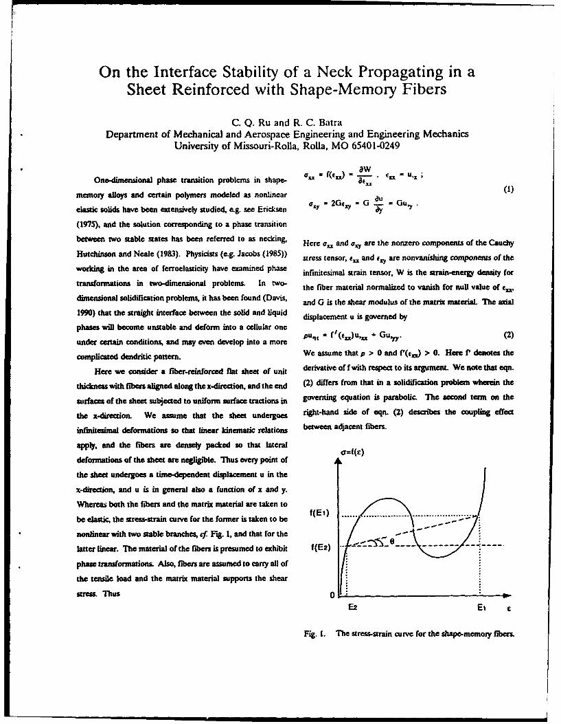
be elastic, the stress-strain curve for the former is taken to be .(. ).
nonlinear with two stable branches, cf. Fig. 1, and that for the - - -
latter linear. The material of the fibers is presumed to exhibit f(E2) . 0--------
phase transformations. Also, fibers are assumed to carry all of
the tensile load and the matrix material supports the shear
stress. Thus 0:
E2 Ei E
Fig. 1. The stress-strain curve for the shape-memory fibers.
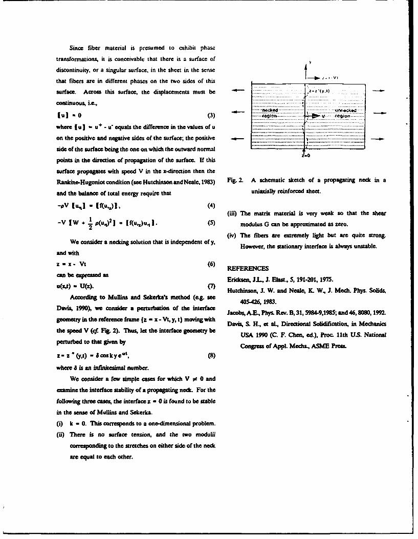
Since fiber material is presumed to exhibit phase
transformations, it is conceivable that there is a surface of
discontinuity, or a singular surface, in the sheet in the sense
that fibers are in different phases on the two sides of this I V
surface. Across this surface, the displacements must be -.-- ....... y)co ti uo si~ .,==::::::::::::::=:::=: ............. I.. ... ..............
continuous, i.e.,.....
-u ....0... (3)n.zkd .[u ] a 0 (3) .... Ir::: $:: : : ::.......... :::: .: :. :: V: .....:.:region; ........
where I u u+ - u equals the difference in the values of u ..... I .,:: ..........
on the positive and negative sides of the surface; the positive ., ..................:..... V.****--.-..---I----I .
side of the surface being the one on which the outward normal
points in the direction of propagation of the surface. If this
surface propagates with speed V in the x-direction then the
Rankine-Hugoniot condition (see Hutchinson and Neale, 1983) Fig. 2. A schematic sketch of a propagating neck in a
and the balance of total energy require that unuaxially reinforced sheet.
-PV (u[j " f(uA)], (4)(iii) The matrix material is very weak so that the shear
-V 1W +. p(u,.j)] = f(u,1 )u,1 ]. (5) modulus G can be approximated as zero.
(iv) The fibers are extremely light but are quite strong.
We consider a necking solution that is independent of y, However, the stationary interface is always unstable.
and with
z - x- Vt (6) REFERENCES
can be expressed as Ericksen, JI, J. Elast., 5, 191-201, 1975.u(x,t) = U(z). (7)
Hutchinson, J. W. and Neale, K W, J. Mech. Phys. Solids,According to Mullins and Sekerka's method (e.g. see
Davis, 1990), we consider a perturbation of the interface Jacobs, A.E., Phys. Rev. B, 31,5984-9,1985; and 46,8080, 1992.geometry in the reference frame {z - x - Vt, y, t) moving with Davis, S. H., et al., Directional Solidification, in Mechaniesthe speed V (cf Fig. 2). Thus, let the interface geomety be USA 1990 (C. F. Chen, ed.), Proc 11th US. National
perturbed to that given by Congress of Appl. Mechs., ASME Press.
z= z *(yt) - Scoskye" t , (8)
where 6 is an infinitesimal number.
We consider a few simple cases for which V o 0 and
examine the interface stability of a propagating neck. For the
following three cases, the interface z - 0 is found to be stable
in the sense of Mullins and Sekerka.
(i) k - 0. This corresponds to a one-dimensional problem.
(ii) There is no surface tension, and the two modulii
corresponding to the stretches on either side of the neck
are equal to each other.
Impact Damage Detection in Composite StructuresUsing Distributed Piezoelectrics
Fu-Kuo Chang
Department of Aeronautics and Astronautics, Stanford University, Stanford, CA 94305
Delamination failure is a major considera- first, upon impact, the comparator compares the
tion in the design of laminated composite struc- measured responses from the piezoelectrics with
tures. The impact of foreign objects is one of the the calculated responses from the analyzer to
common causes of delamination in composite estimate the impact energy and the impact lo-
structures. However, because impact-induced cation. Second, appropriate diagnostic signals
delamination appears inside the laminates, it will be selected by the generator and then dis-
can hardly be detected by visual inspection. There- patched from designated piezoelectric actuators
fore, locating the embedded damage is critically to selected piezoelectric sensors. The measured
important for maintaining and repairing the struc- diagnostic signals from the sensors will then be
tures to prevent a catastrophic failure in service, compared in the comparator with the calcula-
In this presentation, a damage diagnostic tions from the analyzer to determine the damage
method is proposed to detect the location and location and size.
size of the embedded damage in composite struc- Composite plates with and without an im-
tures, using measured dynamic responses from planted delamination were fabricated with four
distributed piezoelectrics built into the struc- pairs of piezoceramics patched on the surfaces.
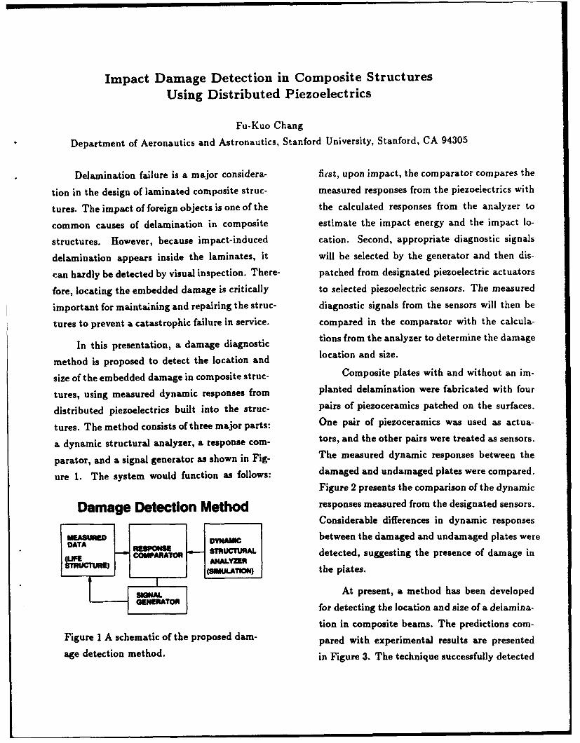
tures. The method consists of three major parts: One pair of piezoceramics was used as actua-
a dynamic structural analyzer, a response com- tors, and the other pairs were treated as sensors.
parator, and a signal generator as shown in Fig- The measured dynamic responses between the
ure 1. The system would function as follows: damaged and undamaged plates were compared.
Figure 2 presents the comparison of the dynamic
Damage Detection Method responses measured from the designated sensors.
Considerable differences in dynamic responses
MUAM=ED DYNAMIC between the damaged and undamaged plates wereTNA RTTMON } STRUTURAl detected, suggesting the presence of damage in
S ,(SOMATION the plates.
G At present, a method has been developedSGENERATOR for detecting the location and size of a delamina-
tion in composite beams. The predictions com-
Figure 1 A schematic of the proposed dam- pared with experimental results are presented
age detection method. in Figure 3. The technique successfully detected
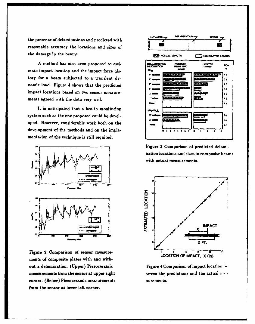
ACrATO -.7 0.eAI"4obthe presence of delamninations and predicted with7
reasonable accuracy the locations and sizes of U I.,
the damage in the beams. ACTUAL LENG, C~3CMCULAT•,LEN
A method has also been proposed to esti- gA"M PImoI L&MI
mate impact location and the impact force his- IM, I%4-- 41 . .
tory for a beam subjected to a transient dy- r a 08
namic load. Figure 4 shows that the predicted 2.,1110I p .... 0
impact locations based on two sensor measure- ra, &%a
ments agreed with the data very well. ,,,.0Now I.
It is anticipated that a health monitoring
system such as the one proposed could be devel- r ,
oped. However, considerable work both on the
development of the methods and on the imple- 0 1 3 4 S 6 7 0 1 2 "
mentation of the technique is still required.
If* Figure 3 Comparison of predicted delami-
"nation locations and sizes in composite beams
with actual measurements.
S ill impl 131111 am "
uJ
•~IEF IMPACT
go 9I III IgII 2W
II ,..,,, ma !U3.IFugc oM 2 FT.
Figure 2 Comparison of sensor measure- 0 5 o0 , 1 20
ments of composite plates with and with- LOCATION OF IMPACT, X (in)
out a delamination. (Upper) Piezoceramic Figure 4 Comparison of impact location I.
measurements from the sensor at upper right tween the predictions and the actual ri,.
corner. (Below) Piezoceramic measurements surements.
from the sensor at lower left corner.
Dynamic Stresses in Composites at Low Temperatures
Piyish K DuttaU.S. Army Cold Regions Research and Engineering Laboratory
Hanover, NH 03755-1290 USA
EXTENDED ABSTRACT
Behavior of polymer composites at low temperature is a indicative of the new increased modulus of the matrix under thengee m a amof rP rh, and the dynamic behavior at low combined effects of low temperature and high strain rate. It isuMPeaMt is gm .s is not that the termo-phyuical b L equation (1) tha•t o(7) will rapidly inc e to thepirobenms of'rac at low t-mpa; Ur, e less interestin thn val oft ier ulime srgth ure 2) if the values ofthe hih N tm perat le - s but becam that the pOhnmenaldevlopmM in ftcmolk ofmpoit in the pagt bed been E.('r) + 1, T,.-7)) in the numerat•i fceses as a nmut ofdriven by tI•e zeds aftm iaderosac which hismrically " t Pempe e dAerease, or strain ra increase or both. f .oweme, nohaveten mone poei with omposi• s at high t than din acqpehimm•ntl -11 ar e urredyawailable to lde thea low -emperatures. O)f pomir. it is true dt the a ryogenic ran individual e of these twofacors Currently anvstigtions elow tpnertme ogre= m o mposite1 have been gudied in the past undeay at RREL to determine the ecls of then ft fctors-d l for qi-ofic a •---aiom- but much wid Vmd -q uM .icatom Of Composites throuh the nWly dve d land
vehicles and amt crafts and new applicatim of composts far One of the examp of these tw combined a n thecvil engmeen mucturms de• nd a neassmment of the focus of =mPte lamint bdhvio is seen i the milts it'the work
m r aoh the dynamic Me at low t PII -I by Dua, Hul and Atamirsno (199). Fimu 3 dsIt is wl known that the lo ring c aupn s moies the runuts of the en a orption teas by a 30-ply AS43502
thme hbehavi of cuqoulats. 7Ue two basic du~ng that INqpiea in ~4OUOlamnated-cmoiewe-ididbthe microuzuctl behavior fcomposlus the do aem . in the himmpb al bit unde the inlunm ofan icidn st m pule ofdastic modulus otthe individual compoms and secondly in the 0nly 180 micOMcmd dmrti It is sOen that im uin l at highechanges in becau1 of mismatched thermal mpagammi vlocitim o impact. emn deaptiom increases beth at roonco•emef ithseompcis Superimd theeseft I -r- (21C) and at low temperature But at iow vedocitieswill be the efies of hlghevin-rme Figur 1 attracted froc. where the primary mode of energy absorptionE, , is by herWuinHrtWkg (1979) shown the drmatc nfece otboth the low amw ddrmsdm as outlined by Cimmk (1982)tmpeau and utn rate c the behavior of the epoxy resinmatfx of vompuies, which would Mx the behavior of thecomposis. Me figure shom that low temqpunture and high strain E. - (P"X4/I(3xl6)'[C(K,++K)/(R/2)] (2)saw icreases the Young•s modulhs value, E of the po•yme moExtending the Rse's (1965) model of cmpotm filmre to tensile whereloading condition, Dua (1992) has shn that the maximum K, -0-u,2)/(E.) ()critical Mwer sem r. () that would be induced in the composites 2
is gven by K2 =O'-v, )/I(rE) (4)
E, and v. are the Young's modulus and Poisson's ratio of the steel
f + W, -7)) (1) identor, respectively, E is the laminate modulus in thidmess3(1-va3 j direction, and u, is the laUuinat' PIsw's ratio. The value E,
dearly decreases with the in*crasad val•s of EB as a rsult of
where Ef - fMer sress, V= fib Mwvolume fraction, E, - matrix m ratmur and strain rate.
modulus, T, - low temperature, and K is an empirical constant
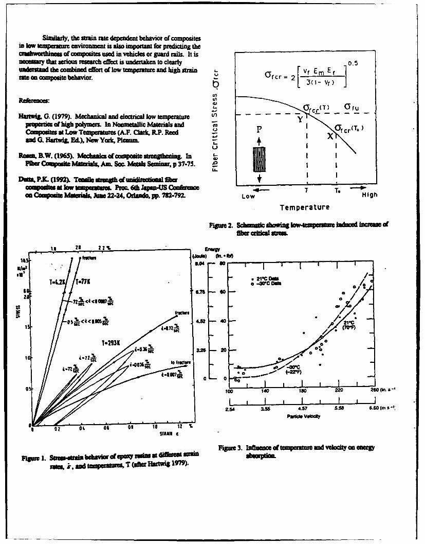
Similarly, the strain rate dependent behavior of compositesin low temperature environment is also important for predicting thecruhathiness of composites used in vehicles or guard rails. It isnromary that serious research effect is undertaken to clearly o0.und-sa the combined effort of low tperature and high strain Vr Em ErMrte compositebehavior. )3( -2 )
(I)
Re 6 , ces: US (T) C;O ru
Hanwig G. (1979). Mechanical and electrical low temperature - - yproperties of Ng polymers. In Nonmetallic hMaterials and i rcr(T,COpMsites at Low Temperatures (A.F. Clark. PP. Reed x crand G. HarWg, Ed.), New York, Plenum. +
Om. B.W. (1965). Mechanics of composite streaogtniag. In I
Fibe Composite MI ials, Am. Soc. Metals Seminar, p 37-75. l I
DOWa PJ. (92). Tuail w=Sh d iUNecoml•fr MWcomposibf at low tmpatue. PMc. 6a Japan-US Camfer W T ToOn CoMpoft 1ateials, Junn 22-24, Odamdo, pp. 782-792. Low High
Temperature
Figure 2. Scomitic showing e -mpm u indiucrd eause offiber w•" s .M
_--. h .b,,
lirs -.
6s 616 -79 I 60 -CDW04zaK
fto
4A52 40
2W6 20
Litil Se i-0036 % to fItawe ORO
to 40IO 220 260 ns-'
2.54 3.55 4.57 5.58 6.60 (m s
02 cc L i I 1,O 06 OA 10 %Z '
]Figure 3. Iuence of temperature and velocity m on wpoFrgpe 1. Sa =d,,ai iehvior dam p ox T sbu at Hartewi 1M)i.Sra .sandl smpzeratre T (af~ter Hlaitwg197;9).
SAINT-VENANT END EFFECTS IN C .,MPOSITE STRUCTURES
Cornelius 0. Horgan,Department of Applied Mathematics, School of Engineering and Applied Science,
-- University of Virginia, Charlottesville, VA 22903
Abstract for the analysis and design of structures using
Thin-walled structures of interest to the advanced composite materials are addressed.U. S. Army, such as rifle barrels, rocket casings,helicopter blades and containment vessels areoften constructed of layers of anisotropic, REFERENCESfilament or fiber-reinforced materials which mustbe designed to remain elastic. A proper Horgan, C. 0., and Knowles, J. K., Recentassessment of end or edge effects in such developments concerning Saint-Venant'sstructures is of fundamental importance to U. S. principle, in Adv. Appl. Mech. (T. Y. Wu and J.
Army technology. The extent to which local W. Hutchinson eds.), 23, 179-269, Academicstresses, such as those produced by fasteners and Press, New York, 1983.at joints, can penetrate girders, beams, plates andshells must be understood by the designer. Thus Hogian, C. 0., Recent developments concerninga distinction must be made between global Saint-Venant's principle: an update, Appl. Mech.structural elements (where Strength of Materials Rev. 42 (1989), 295-303.or other approximate theories may be used) andlocal elements which require more detailed (and Horgan, C. 0., " -" axisymmetric end problem for
more costly) analyses based on exact elasticity, transversely isotropic circular cylinders, int. J.The neglect of end effects is usually justified by Solids Struct. 10 (1974), 837-852.appeals to some form of Saint-Venant's principleand years of experience with homogeneous Choi, I., and Horgan, C. 0., Saint-Venant'sisotropic elastic structures has served to establish principle and end effects in anisotropic elasticity,this standard procedure. Saint-Venant's principle J. Appl. Mech. 44 (1977), 424-430.also is the fundamental basis for static mechanicaltests of material properties. Thus property Choi, L, and Horgan, C. 0., Saint-Venant end
measurements are made in a suitable gage section effects for plane deformation of sandwich strips,where uniform stress and strain states are induced Int. J. Solids Struct., 14 (1978), 187-195.and local effects due to clamping of the specimenare neglected -on- invoking Saint-Venant's Horgan, C. 0., Saint-Venant end effects inprinciple. Such traditional applications of Saint- composites, J. Composite Materials, 16 (1982),Venant's principle require major modifications 411-422.when strongly anisotropic and compositematerials are of concern. See e.g list of Horgan, C. 0., and Simmonds, J. G., Asymptoticreferences and the references cited therein. For analysis of an end-loaded, transversely isotropic,such materials, local stress effects persist over elastic, semi-infinite strip weak in shear, Int. J.distances far greater than is typical for isotropic Solids Structures 27 (1991), 1895-1914.
materials. In this lecture, we provide a survey ofsituations in linear elasticity where anisotropy Crafter, E. C., Heise, R. M., Horgan, C. 0., andand material inhomogeneity induce such extended Simmonds, J. G., The eigenvalues for a self-Saint-Venant end zones. Both static and dynamic equilibrated, semi-infinite, anisotropic elasticproblems are described, although in the latter case strip, J. Appl. Mech. 60 (1993), 276-28 1.
relatively few results are known. The implication
A RO-Wrk,,hop,'Ncw Orlcan nv.93
Fiber Optic Structural Sensing System for a New Road Bridge
R. M. Measures, T Alavie, R. Maaskant, M.Ohn. S. Karr. S. Huang. D. Glennic. C. Wade*,G. Tadros**, and S. Rizkalla#
University of Toronto Institute for Aerospace StudiesFIBER OPTIC SMART STRUCTURES LABORATORY4925 Dufferin St., Downsview, Ontario, CANADA
* City of Calgary, Structures and Facilities, Calgary, Alberta, CANADA** Straight Crossing Inc., 233 - 19th St., N.E., Calgary, Alberta, CANADA#University of Manitoba, Engineering Bldg., Winnipeg, Manitoba, CANADA
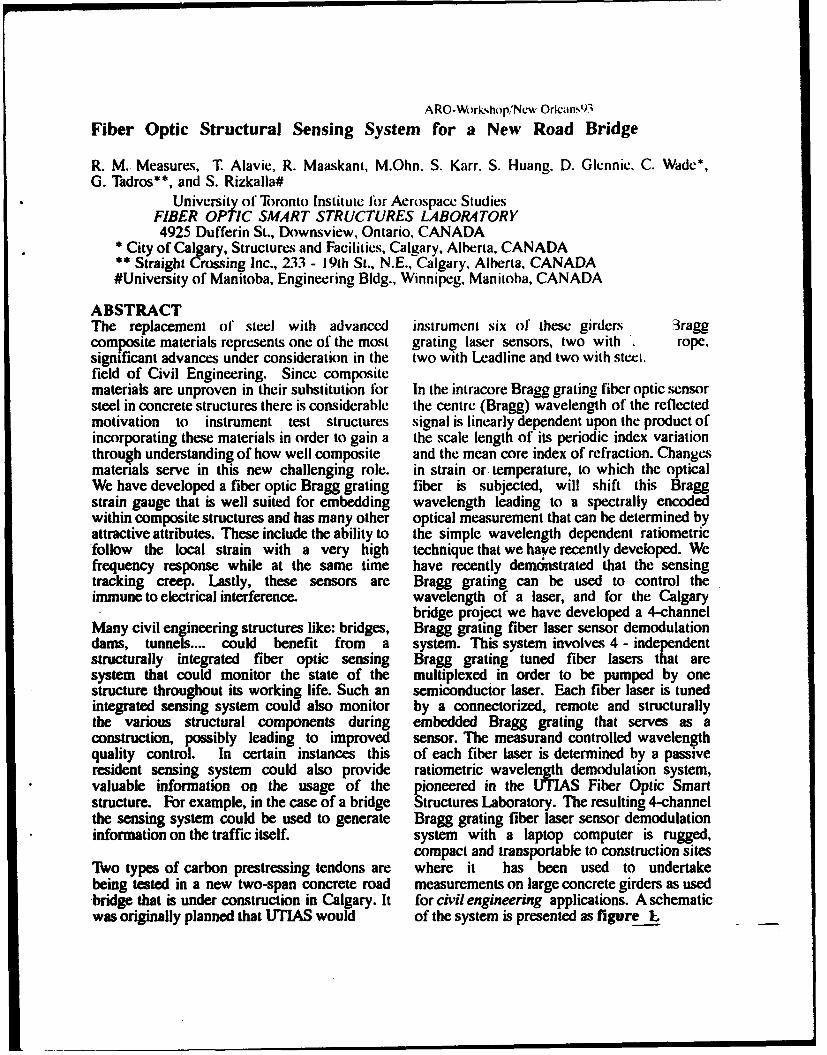
ABSTRACTThe replacement of steel with advanced instrument six of these girders 3raggcomposite materials represents one of the most grating laser sensors, two with rope,significant advances under consideration in the two with Leadline and two with steel.field of Civil Engineering. Since compositematerials are unproven in their substitution for In the intracore Bragg grating fiber optic sensorsteel in concrete structures there is considerable the centre (Bragg) wavelength of the reflectedmotivation to instrument test structures signal is linearly dependent upon the product ofincorporating these materials in order to gain a the scale length of its periodic index variationthrough understanding of how well composite and the mean core index of refraction. Changesmaterials serve in this new challenging role. in strain or. temperature, to which the opticalWe have developed a fiber optic Bragg grating fiber is subjected, will shift this Braggstrain gauge that is well suited for embedding wavelength leading to a spectrally encodedwithin composite structures and has many other optical measurement that can be determined byattractive attributes. These include the ability to the simple wavelength dependent ratiometric"follow the local strain with a very high technique that we have recently developed. Wefrequency response while at the same time have recently demdnstrated that the sensingtracking creep. Lastly, these sensors are Bragg grating can be used to control theimmune to electrical interference, wavelength of a laser, and for the Calgary
bridge project we have developed a 4-channelMany civil engineering structures like: bridges, Bragg grating fiber laser sensor demodulationdams, tunnels.... could benefit from a system. This system involves 4 - independentstructurally integrated fiber optic sensing Bragg grating tuned fiber lasers that aresystem that could monitor the state of the multiplexed in order to be pumped by onestructure throughout its working life. Such an semiconductor laser. Each fiber laser is tunedintegrated sensing system could also monitor by a connectorized, remote and structurallythe various structural components during embedded Bragg grating that serves as aconstruction, possibly leading to improved sensor. The measurand controlled wavelengthquality control. In certain instances this of each fiber laser is determined by a passiveresident sensing system could also provide ratiometric wavelength demodulation system,valuable information on the usage of the pioneered in the UTIAS Fiber Optic Smartstructure. For example, in the case of a bridge Structures Laboratory. The resulting 4-channelthe sensing system could be used to generate Bragg grating fiber laser sensor demodulationinformation on the traffic itself. system with a laptop computer is rugged,
compact and transportable to construction sitesTwo types of carbon prestressing tendons are where it has been used to undertakebeing tested in a new two-span concrete road measurements on large concrete girders as used"bridge that is under construction in Calgary. It for civil engineering applications. A schematicwas originally planned that UTIAS would of the system is presented as figure E
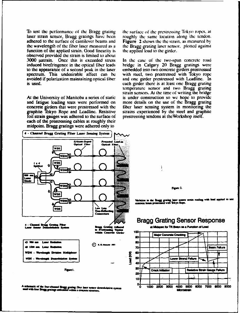
'To test the performance (if the Bragg gr Ln teuraeothpesrsig Tokyo ropes, atlaser strain sensor, Bragg gratings have been roughly the same location along the tendon.adhered to the surface of cantilever beams and Figure 2 shows the the strain, as measured bythe wavelength of the fiber laser measured as a the Bragg grating laser sensor, plotted againstfunction of the applied strain. Good linearity is the applied load to the girder.observed provided the strain is limited to about3000 lpstrain. Once this is exceeded stress In the case ol* the two-span concrete roadinduced birefringence in the optical tibe-r leads bridge in Calgary 20 Bragg gratings wereto the appearance of a second peak in the laser embedded into two concrete girders prestressedspectrum. This undesirable affect can be with steel, two prestressed with Tokyo ropeavoided if polarization maintaining optical fiber and one girder prestressed with Leadline. Inis used. each girder there is at least one Bragg grating
temperature sensor and two Bragg gratingstrain sensors. At the time of writing the bridge
At the University of Manitoba a series of static is under construction so we hope to provideand fatigue loading tests were performed on more details on the use of the Bragg gratingconcrete girders that were prestressed with the fiber laser senising system in monitoring thegraphite Tokyo Rope and LeA.adline. Resistive strains experienced by the steel and graphitefoil strain gauges was adhered to the surface of prestressing tendons at theWorkshop itself.each of the prestressing cables at roughly theirmidpoint. Bragg gratings were adhered only to
4 - Chmaine Brang Grating Fibe Laaar Sensing $yblemv
E,*Uiamhnptd I',Uicd LMW48OpIcal Fiber optical ie
WD ?"
WDm 2
1hh~O m Wh iD ru ae ea.easgwshbdapidwwf
W. aDbumpem ih hy oe
wianersCb'a a00 ac - -a a am ammdgv* a p a
*min ~ ~ ~ ~ ~ A LANftilsmS- ----
4 4C -h"-4co"MFwrfwrDNWM1i"N BW ffI.Ada cat MWagggor jIIII.Rsw a~ Fu un of ig Fur
0 nub KT4041101
A1f Caibmsft cida Mew 300 700 800 900usi wisham Low. Regmi smadon a~ aaiLNuuc. W I
COMPUTATIONAL METHODS FOR PRACTICAL ENGINEERINGDESIGN OF THICK COMPOSITE PLATES AND SHELLS
Alexander TesslerNASA Langley Research Center, Mail Stop 240, Hampton, VA 23681-0001
Design of advanced aircraft, ground-vehicle, and strains which also permits exact satisfaction of upper
naval structures with multi-layered organic-matrix com- and lower surface stress equilibrium conditions. The
posite materials requires easy-to-use computational virtual work principle (and, in dynamics, Hamilton'stools which provide accurate predictions of structural variational principle) is applied to derive the
response and integrity under mechanical, thermal, and appropriate equations of equilibrium/motion and engi-dynamic loads. Unlike metals, composites commonly neering boundary conditions. As analytical results mdi-
possess significantly lower strength and stiffness in the cate, the theory is capable of accurately predicting dis-
direction transverse to the reinforcing fiber as compared placements, natural frequencies, mode shapes, and
to the fiber direction; hence, transverse shear and nor- three-dimensional strains and stresses. It yields im-
mal strain and stress effects can significantly contribute proved predictions over the first-order theory, particu-
to the response and failure of such structures. Conse- larly for thick laminates and higher vibration frequen-quently, computational tools that are employed in the cies. Moreover, thickness-stretch modes and natural
industrial environment must accurately predict these so- frequencies, which are critical for delamination initia-called "secondary" stains and stresses. Conventional tion and which are suppressed in the first-order andshear-deformable theories that are prevalent in com- many higher-order theories, are accurately predicted.
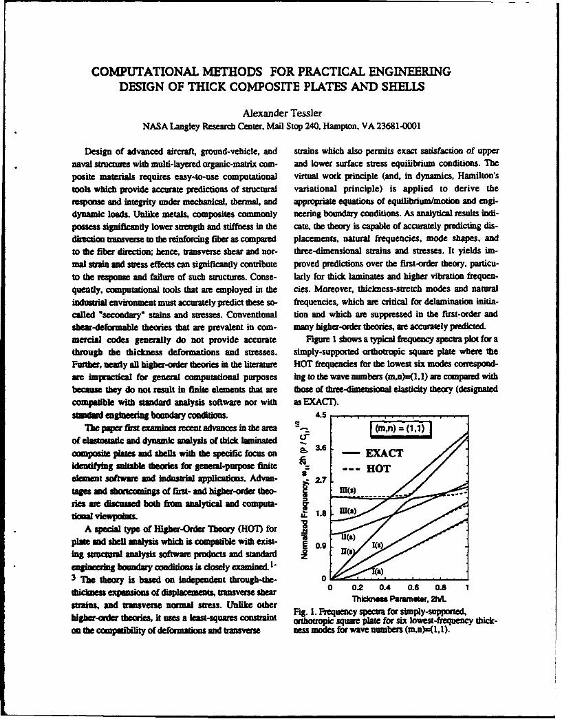
mercial codes generally do not provide accurate Figure I shows a typical frequency spectra plot for athrough the thickness deformations and stresses. simply-supported orthotropic square plate where theFurther, neawly all higher-order theories in the literature HOT frequencies for the lowest six modes correspond-are impractical for general computational purposes ing to the wave numbers (m,n)=(,1) are compared withbecause they do not result in finite elements that are those of three-dimensional elasticity theory (designated
compatible with standard analysis software nor with as EXACT).standard engineering boundary conditions. 4.5
The paper fim examines recent advances in the area (mn) = (1,1)of elastostatic and dynamic analysis of thick laminated -
composite ptm and shells with the specific focus on 3. EXACTidentifying suitable theories for general-purpose finite --- HOTelement software and Industrial applications. Advan- . 2.7tages and shortcomings of first- and higher-order theo- nm(S)ies ae discussed both from analytical and computa-donal viewpoiuts. .
A special type of Higher-Order Theory (H07) for .plat and shell analysis which is compatible with exist- 0.9 US
ing structmal analysis software products and standard z0eierg boundary conditions is closely examined. a
3 The theory is based on independent through-the- 0thiciess pnon of displacements, trnsverseshear 0 0.2 0.4 0.6 0.8 1
strains, and transverse normal stress. Unlike other Thcknm Parameter, 2M.Fig. 1. Frequency spectra for simply-supported,
higher-orier theories, it uses a least-squares cotint hotrapic square plate for six lowest-frequency thick-on the compatibility of deformations and transverse ness modes for wave numbers (m,n)-(1,1).
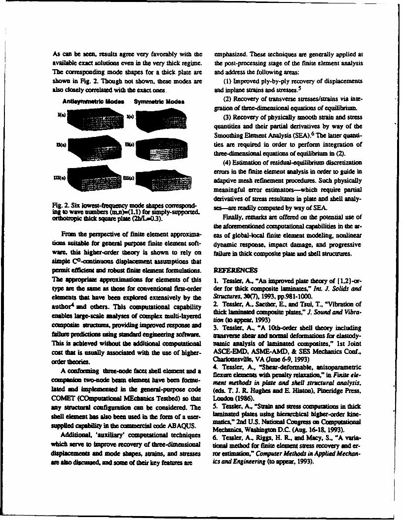
As can be seen, results agree very favorably with the emphasized. These techniques are generally applied atavailable exact solutions even in the very thick regime, the post-processing stage of the finite element analysisThe corresponding mode shapes for a thick plate are and address the following areas:shown in Fig. 2. Though not shown, these modes are (1) Improved ply-by-ply recovery of displacementsalso closely correlated with the exact ones and inplane strains and stresses. 5
AnUsamynWtrie Mod.. Symmtridc Modes (2) Recovery of transverse stresses/strains via inte-
gration of three-dimensional equations of equilihrium.fIt) (3) Recovery of physically smooth strain and stress
quantities and their partial derivatives by way of the
Smoothing Element Analysis (SEA).6 The latter quanti-ties are required in order to perform integration of
three-dimensional equations of equilibrium in (2).
(4) Estimation of residual-equilibrium discretizationerros in the finite element analysis in order to guide in
Ir(w) Mu) adaptive mesh refinement procedures. Such physicallymeaningful error estimators-which require partial
derivatives of sts resultants in plate and shell analy-Fig. 2. Six lowest-freluenc mode shapes COSPU se•- readily computed by way of SEA.ing to wave numbers m,n)-(1,1) for simply-supported,
(thobopic thick square plate (2" .3). Finally, remarks are offered on the potential use ofthe aforementioned computational capabilities in the ar-
From the perspective of finite element approxima- eas of global-local finite element modeling, nonlineartimes suitable for general purpose finite element soft- dynamic response, impact damage, and progressiveware, this higher-od theory is shown to rely on failure in thick composite plate and shell structrum .smple C0 -comtinuous displacement assumptions thatpermit effcient and robust finite element formulations. REFERENCES"Tle appropriate approimatons for elements of this 1. Tessler, A., "An improved plate theory of (1,2)-or-type ae the same as those for conventional first-order der for thick composite laminates," Int. J. Solids andelements that have beeu explored extensively by the tnicures, 30(7), 1993, pp.981-1000.author4 and others. This computational capability 2. Tessler, A., Saether, E., and Tsui, T., "Vibration ofenables large-scale aalyses of complex multi-layered thick laminated composite plates," J. Sound and Vibra-
ecoc (to appe1r, 1993)ctmposite sructmes, providing improved response and 3. Tessler, A., "A 10th-order shell theory includingfilure predictiom using stoandard engineering softwar transverse shear and normal deformtin for elastody-
This is achieved without the additional computational namic analysis of laminated composites," 1st Jointcost that is usually associated with the use of higher- ASCE-EMD, ASME-AMD, & SES Mechanics Coal,
order theories. Carlottesvlle•, VA (June 6-9, 1993)4. Tessler, A., "She~ar-deformable, anisopanamesticA conforming three-node facet shell element and a 4 eseA,"ba-eombeAcmpanionforming t hree-node etshe element aend a flexure elements with penalty relaxation," in Fite ale-
companio two-node beam element have been forua- ~mert methods in plote and shell structural analysis,lated and implemented in the general-purpose code (e&s. T. J. R. Hughes and E. Hinton), Pineridge Press,COMET (COmputational MEchanics Testbed) so that London (1986).any sructua configuration can be considered. The 5. Tessler, A., "Strain and sess computations in thick
shell element has also been used in the form of a user- laminated plates using hierarchical higher-order kine-supplied capab'lity in the coamnvial code ABAQUS. matics," 2nd U.S. National Congress on Computational
sudliedal, capailitry'inth commerctional tcdqus UMechanics, Washington D.C. (Aug. 16-18, 1993).Additional, 'auxiliary' computational techniques 6. Tessler, A., Riggs, H. R., and Macy, S., "A varia-
which serve to improve recovery of three-dimensional timEl method for finite element stress recovery and er-displacements and mode shapes, strains, and stresses mr estimation," Computer Methods in Applied Mechan-me also discussed, and some of their key feotes am e ics and Engineering (to appear, 1993).
STATIC AND DYNAMIC RESPONSE OF MODERATELY THICKLAMINATED BEAMS WITH DAMAGE
Ronald C. AverillDepatm•ent of Materials Science and Mechanics
Michigan State UniversityEast Lansing, MI 48824-1226
l-troduction sions in the original theory that give rise to the problemat-The currently available layerwise (or discrete layer) ical C' continuity requirement. In order to ensure the
theories provide significant improvements over the equiv- continuity of transverse shearing stresses, a constraint con-alent single-layer (or smeared) theories for analysis of thin dition is then added to the statement of the displacementand moderately thick laminated structures. For practical field and its associated functional, so the new form of theapplications. however, all existing discrete-layer theories theory can be shown to have the same properties as thegive rise to finite element models that are either too com- original theory of DiSciuva. By imposing such a constraintputationally expensive or poorly suited for general pur- via the penalty function concept, the transverse shearpose analysis. In order to take advantage of this powerful stresses are made continuous without introducing addi-class of laminate theories, a new generalized discrete-layer tional degrees of freedom. Furthermore. CO continuity oftheory and an associated computational model for the all degrees of freedom is maintained, allowing for a sim-analysis of moderately thick laminated beams has been pie, efficient, and accurate finite element model of the gov-developed1. The theory assumes a piecewise linear distri- erning equations.bution of the inplane displacements through the thickness The finite element model based on the above laminateof the laminate, and satisfies the stress continuity condi- theory takes advantage of the interdependent interpolationtions at the interface between each layer. In this way, the concept introduced by Tessler and Hughes (Comp. Meth.number of degrees of freedom in the theory is made inde- AppL Me& Eng., Vol. 39, pp. 311-335, 1983). As a result.pendent of the number of layers in the laminate. the linear part of the constraint is satisfied identically, the
Unlike available theories, the current theory is spe- approximation order of the element is effectivelyciaily formulated to be ideally suited for solution by the increased without adding more degrees of freedom, andfinite element method. A tPo-noded beam element has the possibility of shear locking is eliminated. The pro-been developed that combines the penalty method with an posed discrete-layer finite element model is thus muchinterdependent interpolation scheme, resulting in a simple more efficient. convenient and widely applicable than anyand efficient & element that is rank sufficient, accurate one developed to date.for both thick and thin beams, and has no apparent defect.The accuracy of the computational model has been dem- Numerical Resultsonstrated for static and vibration analysis of thin and thick A simply-supported (0/d/90/0) beam has been ana-laminated beams, with and without delaminations and/or lyzed, where d represents a full-length delamination, mod-ply damage. It has been shown that layerwise variations of elled as a very thin compliant layer. The normalized centerthe inplane displacements must be taken into account deflection due to a sinusoidal load is plotted versus thewhen modelling either the global or local response of dam- span-to-thickness ratio in Figure 1. The center deflectionsaged laminates, are normalized by those of the exact solution obtained by
Pagano (Q. Comp. Mat., Vol. 3, pp. 398-411, 1969). ForApproach beams with an aspect ratio less than 500, the first-order
In the current theory, the continuity requirements on shear deformation theory (FST) and the third-order theorythe displacement variables of the discrete-layer laminate of Lo, Christenson, and Wu (LCW) do not accurately pre-theory of DiSciuva (J. Sound and V[b., Vol. 105. pp. 425- diet the global deflection behavior, while the current dis-"442, 1986) awe reduced by momentarily relaxing the con- crete-layer model (ZZ) is nearly exact for all thicknessdition of continuous transverse shear stresses. Two new ratios greater than 8.degrees of freedom are introduced to replace the expres- The reason for the poor predictions of the equivalent
single layer theories (FST and LCW) is illustrated in Fig-ure 2, where the inplane displacement at the end of the
Extension of the theory and computational beam is plotted versus the normalized thickness coordinatemodel to plateI and shells is currently underway.
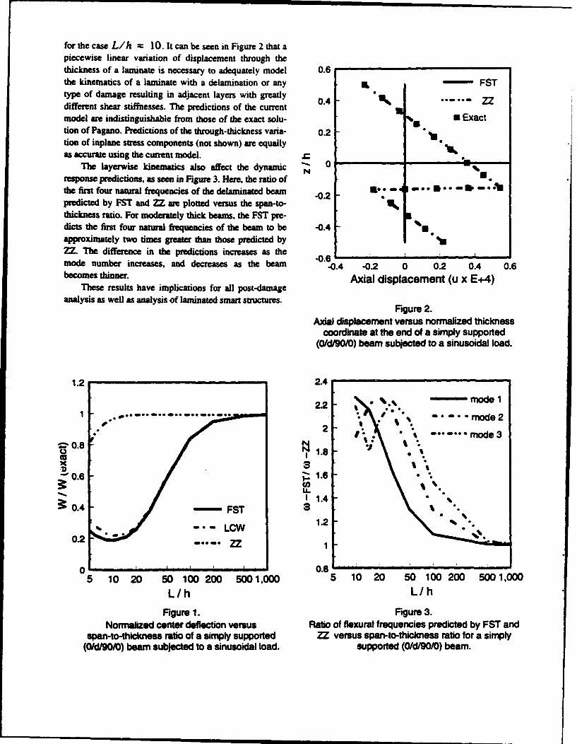
for the case L/h = 10. It can be seen in Figure 2 that apiecewise linear variation of displacement through thethickness of a laminate is necessary to adequately model 0.6the kinematics of a laminate with a delamination or any L- FSTtype of damage resulting in adjacent layers with greatly 0.4 ".... ZZdifferent shear stiffnesses. The predictions of the currentmodel are indistinguishable from those of the exact solu- s U Exacttion of Pagano. Predictions of the through-thickness varia- 0.2tion of inplane stress components (not shown) are equallyas accurate using the current model. .
The layerwise kinematics also affect the dynamic N 0response predictions, as seen in Figure 3. Here, the ratio of •the first four natural frequencies of the delaminated beam -0.2predicted by FST and ZZ are plotted versus the span-to-thickness ratio. For moderately thick beams, the FST pre-dicts the first four natural frequencies of the beam to be -0.4 11approximately two times greater than those predicted by *12Z The difference in the predictions increases as the I-0.6 ' ';mode number increases, and decreases as the beam -0.4 -0.2 0 0.2 0.4 0.6becomes thinr. Axial displacement (u x E+4)
These results have implications for all post-damageanalysis as well as analysis of laminated smart structures.
Figure 2.
Axial displacement versus normalized thicknesscoordinate at the end of a simply supported
(0/d/90/0) beam subjected to a sinusoidal load.
1.2 2.42.2 - ' 0 .
2.2 * model2
2 " it ....... mode3 I0.8 % 1.•
B L1.2
0. 0.
1.2". ,
5 10 20 50 100 200 5001,000 5 10 20 50 100 200 5001,000
L/h L/h
Figure 1. Figure 3.Normalized center deflection versus Ratio of flexural frequencies predicted by FST and
span-to-thickness ratio of a simply supported ZZ versus span-to-thickness ratio for a simply(0/d/90/0) beam subjected to a sinusoidal load. supported (0/d/90/0) beam.
ACTIVE COMPOSITE TORQUE-PLATE FINSFOR SUBSONIC MISSILES
Ron BarrettAemrpace Engineering Department. University of Kansas. Lawrence. KS 66045 U.S.A.
A study on the working principles and structural The torque-plate fin design of Barrett (19921'2-3) used
arrangements of active composite torque-plate missile fins is directionally attached piezoelectric (DAP) elements bonded to
presented. The design evolution from active fin twist to torque- an isotropic substrate antisymmetrically. The plate was
plate design shows that early designs proposed by optimized to provide the maximum twist from commercially
experimenters like Crawley, Lazarus and Warkentin (1989) available stock. However, another design which uses symmetric
provided a valuable starting p6int for a host of new designs. elements can provide significantly higher twist deflections. An
This early design of adaptive lifting surface was composed of a examination of the plate performance using laminated plate
bending-twist coupled graphite-epoxy plate which had lead theory clearly illustrates the potential of this new arrangement.
zirconate titanate (PZT) piezoelectric sheets laminated on either Using the analysis techniques outlined by Barrett
side of the plate. As the PZT sheets were alternatively (19921.2.3). the properties of DAP lamina can be estimated.
contracted and extended to induce a bending deformation. the Fundamentally. they are modeled as having different stiffnesses
plate also twisted. The plate was exposed to air loads, in the longitudinal and lateral directions, but with equal
Accordingly. small active twist deformations resulted in larger actuation strains. For a symmetric torque-plate with an isotropic
deflections through active aeroservoelasticity. substrate and a main spar that stiffens the plate in bending, the
This first successful design lead to the development of the laminate twist can be solved for as shown in equation 1.
"trque-plate fin configuration. One of the design compromises
that was necessary for the bending-twist coupled plate design Kir2 hI(3i ÷ s)I, -(3n ÷a (I)
was to make it thick enough so that bending loads could be
carried. Unfortunately, as the thickness was increased, the
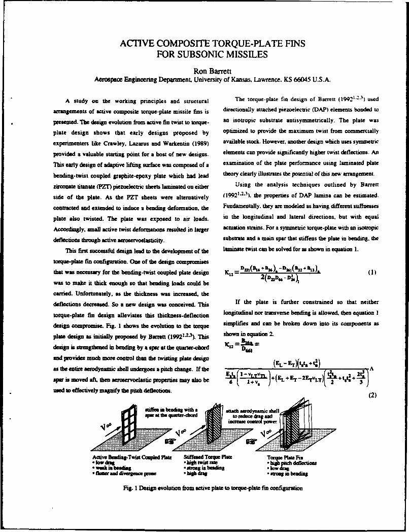
deflections decreased. So a new design was conceived. This If the plate is further constrained so that neither
torque-plate fin design alleviates this thickness-deflection longitudinal nor transverse bending is allowed, then equation 1
design compromise. Fig. 1 shows the evolution to the torque simplifies and can be broken down into its components as
plate design as initially proposed by Barrett (19921.2.3). This shown in equation 2.
design is strengthened in bending by a spar at the quarter-chord K12 =BD,
and provides much more control than the twisting plate design (EL- Er)tt.+t!)
as the entire aerodynamic shell undergoes a pitch change. If the X~ +~ A
sar is moved aft, then aeroservoelastic properties may also be )6E i + v, -~L 2Ev.)1L+ &)6 obe, 2 3
used to effectively magnify the pitch deflections. (2)
Active Bealig-Twist Copled late Stiffened Torque Plate Torque Platu Fin
weakis bendingstrong in beading lFiur g 1nd divesrgn revo ut o drac p t uoe in eon faiog
Fig. I Design evolution from active plate to torque-plate fin configuration
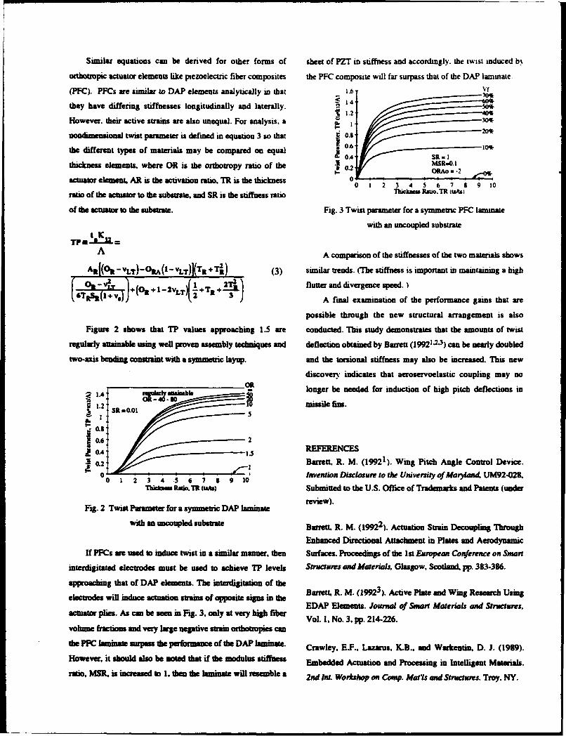
Similar equations can be derived for other forms of sheet of PZT in stiffness and accordingly. the twist induced b%
orthovopic actuator elements like piezoelectric fiber composites the PFC composite will far surpass that of the DAP laminate.
(PFC). PFCs are similar to DAP elements analytically in that 1.6 ft
they have differing stiffnesses longitudinally and laterally. 1. -0
However, their active strains are also unequal. For analysis. a 0nondiniensional twist parameter is defined in equation 3 so that 0.8
the different types of materials may be compared on equal0. 0
thickness elements& where OR is the orthotropy ratio of the So.
actuator element. AR is the activation ratio. TR is the thickness 00! !!R 11 2 . 10:
ratio of the actuator to the substrate, and SR is the stiffness ratio Thck Rami. TR uaftl
of the actuator to the substrate. Fig. 3 Twist parameter for a symmetric PFC amIne
with an uncoupled substrate
A A comparison of the stiffuesses of the two materials shows
Altf(0 - VLT) - ORA(I -vLT)](Tlt + Ir.) (3) similar trends. (The stiffness is important in maintaining a high
00 -IV flutter and divergence speed.)(i~ ). + (Olt + I- 2vLT0~+TR +') A final examination of the performance gains that are
possible through the new structural arrangement is also
Figure 2 shows that TP values approaching 1.5 are conducted. Ibis study demonstrates that the amounts of twist
regularly attainable using well proven assembly techniques and deflection obtained by Barrett (19921.2-3) can be nearly doubled
two-axis bending constraint with a symmetric layup. and the torsional stiffness may also be increased. This new
discovery indicates that aeroservoelastic coupling may no
IA .14amb longer be needed for induction of high pitch deflections in
missile fins.0.2:S8 00
0.4 REFERENCES0.2 Barrett. R. M. (19921). Wing Pitch Angle Control Device.
00 1 Invent ion Disclosure to the University of MarylandA UM92-028.Thickms ana. Th(ata~) Submitted to the U.S. Office of Trademarks and Patents (under
Fig. 2 Twist Parameter for a symmetric DAP laminate rve)
with an uncoupled subsumae Barrett. R. M. (19922). Actuation Strain Decoupling Through
Enhanced Directional Attachment in Plate and AerodynamicIf PFCs wre used to induce twist in a similar manner. then Surfaces. Proceedings of the I1st European Conference on Smart
interdigitated electrodes must be used to achieve 1? levels Structures and Materials. Glasgow, Scotland. pp. 3&3-386.
approaching that of DAP elements. The interdigitation of the Bret .M 193.Atv lt n igRsac snelecrods w inuceacuboustrms;of ppoitesig inthe EDAP Elements. Journal of Smart Materials and Structures,
actuator plies. As can be see in Fig. 3, only at veyhg ie Vol. 1, No. 3. pp. 214-226.volume fractions and verny large negative strain orthotropies can
the PWC laminate surpass the performance of the DAP lamninate. Crawleyr, E.F.. Lazarus, K.B.. and Warkentin, D. J. (1989).However, it should also be noted that if the modulus stfns Embedded Actuation and Processing in Intelligent Materials.ratio, MSR. is increased to 1. then the laminate will resemble a 2nd ftu Workshop on Cooup. MallIs and Structures. Troy. NY.
ARO Watkb"hepeDrneaMRpm iWft aCompoiso SUMMON.No rskd LA -Asp. IM9
OPTIMAkL VIBRATION CONTROL OF NiTINOL-REINFORCED COMPOSITES
A. Baz ad I. ItoMechanical Engineering DepubncntThe Catholic Univasity of America
Washington DC 20064
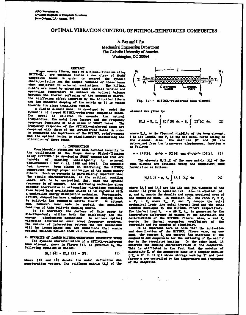
tShp. meenry fibers, made of a Nichel-Tianium alloy 1 - L- *lU(IEITINOL). are emedded Inside a new class or SA Pa. Pacharacteristics and the damped response of these beams Pt ~a.amaaa~~rL~I~fibers are tuned by adjusting their Initial tension sadAVT1Moperating temperature to achieve an optimal balance V1 Vbetween the thermal softening of the composite matrix.the stiffeningt effect ioparted by the activated fibers Fg 1 IIC-anocdbweeetan~d the enhanced damping of the matrix as it Is heated-NIIO-eifedbe eeettowards its glass transition region.
A finite element model is developed to model th element are given by:dynamics of damped NITINOL-re infrcred composite beoom.The model Is utilized to compute the natural 1 9frequencies, the modal less factors and the frequency - ,,. IW, dx - P.[ C(Cd. ()respos functions of this class of 94A5T beams. The JK) t .ff CTc xfrequency responses of the HITIt4L-reinforced berns are acompared with these of the unr*inforced beams in orderto emphasize the Importance of the Nf KYINL reinforcemet where 41 is the flexural rigidity of the been element.and Its optimal tuning in significantly attenuating the I Is Its length, and Pa is the net axial force* acting onvibration of these beams, the element. Also, the matrices (C] and (01 are
determined from the transverse dispLacement, function w1. DIWhOWlCZ1N am follows:Considerable attention has been dvo-rted recently to
the utilization of the Shape Memory WIckcel-Tltanlim w - (AIll]. de~dx - ICull1 and AtdO6dx (1111,8. (3)alloy CNXTIJSO Iin developing ULID composites that arecapable of adapting Intelligently to exterhaLi The elements I(.(i.J) of the mass matrix (k], of thedisturbances C Dus at al. IM9 and 1991). The emphasis beom element ane obtained using the consistent MaSShas, however, been placed on stiffening the NITINOg. formulation as follows:composites through proper activation of the shape memoryfibers. Such an emphasis is particularly Important when Alsj]d 4the static characteristics. as the critical buchingt .)%('.J) a 0. As A!CA)d 4loads, are to be controlled. gut. whn the dynoamiresponse Is of concern, the stiffening **chanism alowebecomes Ineffective in attenuating vibrations resulting whoer (Al I and [A I are the Ith and jth elements of thefrom broad 'band excitations unless it Is augaenteg with vector (Al given 4 equation (3). Also In equation (4).a controlled ener3 dissipation mechansim. Fortunately. V, An A, denote the density and cross sectional ares ofNITINL composites have a unique source of damping which the composite beam. In equation (2). the force . -FP,,in built-in the composite matrix Itself. No attempt # , - T, Wmer - . P& and Tt demote the axialhas, homweve. been made to exploit the excellent mechanical leao". Mwh axial thermal laed and the totalfeatures of this built-In damping source. tension developed lay the NITINOL fibers respetively.
It is thatrefore the purpose of this paper to The thermal load Pt a A9fI 4A,. is generated by thesimultaneously utilize both the stiffening and the temperature difference AD caused by the activation andenergy dissipation mechanisms to achieve optimal Ge-fttivation of the WIYDIMM fibers. Also. a and 2.vibration attenuation ever broand frequency spectrum. donote the thermal expansion coefficient, of theThe mature of Interaction between the two mechanisms composite and its modulus of elasticity.will he Investigated and the conditions that srmIt Is Important here to net* that the activationOptimal balance between them will be determined. and deactivation of the NFITIML fibers vary. on one
hand, the tension Tt, and control the stiffnes of the2. DYNMgICS Or DAWU XrZjbog-pzCpWr3= CMW Mgr mun composite and compensate for the softening of the matrixThe dynamic characteristics of a N!TIJMfl-reinfore die to the associated beating. On the other heand, Itbean element. shown In Figure (1). is governed by~~ am controls the doming characteristics of the composite.following equation of motion: Thin Is attributed to the fact that the modulus of
elasticity to of the composite bean Is a complex modulusIC, - V(I *1 1) b" setorage *Adulus Vand tons
utmere ~ ~ ~ ~ ~ ~ ~ ~ ~ aco vI n I eoetendldfeto are controlled by the temperature and frequencyacceleration vectors, The stiffness matrix 12.1 of the heoost
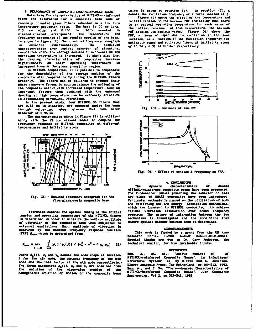
3. DIOHANE O DAPEDNITOL-EXUORCD ~which Is given by equation (1). in equation (5). wbMaterials The characteristics of NITINOL-reinforced dnt h xiainfeunyo oc oae tj
beams are determined for a compoite bea mad of Figure (3) shows the effect of the temperature and
randmlyorinte glss iber emeddd I a ow ure Initial tension on the maximum MF? Indicating that thererandmlyorinte glss iber emeddd i a ow ure Is an optimal operating temperature for each value of
temperature polyester resin. The beam Is 30 cm long, the Initial tension. At that temperature. the maximum2.5 cm wide and 0.156 ca thick mounted In FR? attains Its minimam value. Figure (4) shows theclamped-clamped arrangement. The temperature and FRI. at beam mid-span due to excitation at the samefrequency dependence of the complex modulus of the beam, location, as a function of the excitation frequency forIs shown In Figure (2). Such reduced frequency nomograph optimally tuned and activated fibers 'at initial tensionsIs obtained experimentally. The displayed of 13. 34 and 31. 14 N/fiber respectively.characteristics show typical behavior of structuralcomposites where the storage modulus V decreases as the ________________
operating temperature Is Increased. It shows also thatthe damping character sties of composites Increasesignificantly as their operating temperature is L 4 c C ZIncreased towards the glass transition region. 0
In NITINOL composites, It io possible to compensatefor the degradation of the storage modulus of thecomposite with temperature by tuning the NITINOL fibersproperly. The fibers can be tallored to produce their 4- U4-------
phase recovery forces to counterbalance the softening of SAW__ __the composite matrix with Increased temtperature. Such anImportant feature when combined with the enhanced aMdamping at high temperature can be extremely effective __VW______________-4___
In attenuating structural vibrations. is tA U Is a 40In the present study, four MITIMOL 55 fibers that WUIL TENSION (*ffi)
are 0.5S5 me In diameter, are embedded Inside the beamthrough vulcanized rubber sleeves that have outer Fig. (3) - Contours of iso-FR.diameter of 0. 95 ma.
The characteristics shown In Figure (2) Is utilized 11along with the finite element model to compute thefrequency response of NITINOL composites at differenttemperatures and Initial tensions.PA
49 Fig. (4) -Effect of tension & frequency on FR?.
RAS ol .10The dynamic characteristics of dampedfPiU~~f PsW ITINOL-reinforced composite baeas have been presented.
The fundamental iseues governing the behavior of thisFig. (2) - Reduced frequency nomograph for the new clase of $NAR composites have been introduced.
fiberglass/roesin composite bean Particular emphasis Is placed on the utilization of boththe stiffening and the energy dissipation mechanisms.which are Inherent to NITINOL composite, to achieve
Vibration control The optimal tuning of the Initial optimal vibration attenuation over broad frequencytens ion and operating temperature of the NITINOL fibers spectrum. The nature of Interaction between the twoIs determined In order to minimize the maximum amplitude machanisoms is investigated end the conditions thatof vibration of the composite beam when subjected to esure optimal balance between them Is determined.external excitations. Such amplitude of vibration inmeasured by the maximum frequency response function AIDOULOGDE((1W) Pe,, which Is determined from: This work Is f~unded by a grant from the US Army
Research Office (Greant number DAALO3-89-G-0064).Special thanks are due to Dr. Gary Anderson, the
makX 4L 16()* i /e (5a technical moiofor his invaiuablW Inputs.
where #m11 ). w. and %~ denote the mode shape at locationt Do. A.. a t. al., "Active control of ofI for the nth mode, the natural frequency of the nth NITINOL-reinforced Composite Beam", In Inotalligentmod, and the loss factor at the nth mode respect ively.-% Structural System., ad. by' R.Tzou and C. Anderson.The three parameters *,(I). wo, and % are obtained from Klomoer Academic Press. The Netherland. pp. 169-213, 1992.the Solution of the elgenvalue problem. of th Boxs. A.. and J. Me. 'Thermo-dymamic Characteristics ofhomogeneous equation of motion of the composite bowU NITINOL-Reinforced Composite Beamv% J. of omoIte
Emnieearing, Vol.2, pp.S2 7-542, 1M2.
High-Frequency Composite Beam Dynamics
A.R. Atilgan," V.. Berdichevsky," C.E.S. Cesnik," D.H. Hodges,"and V.G. Sutyrn""
School of Aerospace Engineering, Georgia Institute of TechnologyAtlanta, Georgia 30332-0150
The classical theory of composite beam dispersion curves of ID theory and exactvibrations fails to predict a correct dynamical dispersion curves has been proposed by V.response if high frequencies (oh/G/p 1, w - Berdichevsky about 15 years ago. Later, itfrequency, h - beam thickness, G shear was applied to developing an improved IDmodulus, p - mass density) and short waves ( hM theory of isotropic homogeneous (or layered)- 1, 1 - wave length) are involved. We are plate, shells and beams by V. Berdichevsky,developing an improved theory of composite Le Khank Chao, M. Riazantzeva and S.beam vibrations which captures the major Kvasbnina. The method has proven to behenoma unaccessiblet theory. very efficient. In the study in progress now,
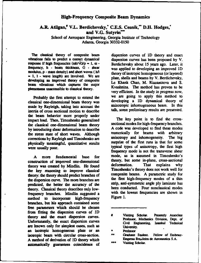
Probably the first attempt to extend the we are going to apply this method toclassical one-dimensional beam theory was developing a ID dynamical theory ofmade by Rayleigh, taking into account the anisotropic inhomogeneous beam. In thisinertia of cross sectional motion to describe talk, some preliminary results are presented.the beam behavior more properly underimpact load. Then, Timoshenko generalized The key point is to find the cross-the classical one-dimensional beam theory sectional modes for high-frequency branches.by introducing shear deformation to describe A code was developed to find these modesthe stress state of short waves. Although numerically for beams with arbitragycorrections by Rayleigh and Timoshenko are anisotrpy and inhomogeneity. The bigphysically meaningful, quantitative results surprise of the first runs is that for somewere usually poor. typical types of anisotropy, the first high
frequency mode is not the transverse shearA more fundamental base for mode, as is assumed in Timoshenko's
construction of improved one-dimensional theory, but some in-plane, cross-sectionaltheory was created by Mindlin. He found deformation. That explains whythe key reasoning to improve classical Timoshenko's theory does not work well fortheory: the theory should predict branches of composite beams. A parametric study forthe dispersion curve. The more branches are the first high-frequency modes of a thinpredicted, the better the accuracy of the strip, anti-symmetric angle ply laminate hastheory. Classical theory describes only low- been conducted. Four nonclassical modesfrequency branches. Mindlin suggested a with the lowest frequencies are shown inmethod to incorporate high-frequency Figure 1.branches, but his approach contained somefree parameters which should be chosenfrom fitting the dispersion curves of IDtheoy an th exat diperion urve. # Visiting Scholar. Presently Associazetheory and the exact dispersion curves. Professor, Mechmics Division, Dept. ofUnfortunately, the exact dispersion curves Civil Engineaing, Itanbul Technicalare known only for simplest cases, such as University.an isotropic homogeneous plate or an Professorisotropic beam with circular cross-section. Graduate SUdrM. Fellow of Embraer-A method of derivation of ID theory which Empre Bra~ileira de Aeronautica S.A.automatically guarantees coincidence of Visiting Scholar.
g~Le
0'We
4bCP
CP
GENERSLIZED STRESS AND FAILURE ANALYSIS OF INHOMOGENEOUSANYSOTROPIC STRUCTURES
Alexander E. Bogdanovich and Christopher M. PastoreTextile Material Science, North Carolina State University, Raleigh, NC 27695 U.S.A.
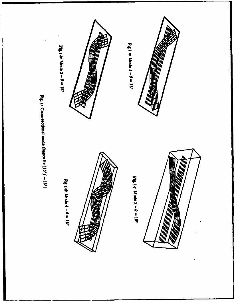
A method of structural analysis based on the where qO > 0. The first step of the initial failure analy-spline-qublayer approach is presented. This method sis is to define the load, point and mode of initial fail-was developed to understand the mechanical behavior mue. After a computer "scanning" of the plate volumeof inh!mogeneos structures, particularly composites, is applied to all six stress components normalized byas existing commercial packages do not satisfy the fun- corresponding ultimate stress values (and designateddamental requiremets. In particular, the method is ca- further with an asterisk), the greatest is obtained. Inpable of: this particular example, the maximum stress criterion* analysis of laminated composite smuctures providing was first satisfied at qo=0.779 Msi for the uy* compo-continuous through the thickness distribution of normal nent at x = y = 0.5a, and z=0. Then, in the parallele-stresses piped zone around this point in which the inequality* analysis of textile composites with elastic propertieschanging through the volume of the composite o 0.98 (2)eanalysis of progressive damage of composites
Fo the Correct prediction of the behavior of is satisfied, the moduli E22, G12 and G32 have beenstructures both the conditions of continuity for dis- reduced (10 times for this particular calculation).
placements and transverse messes must be satisfied at Equation (2) defines the damaged zone extending
each interface of the structure. The continuity of trans- over the region 0.45 < x/a < 0.55 and 0.45 < y/a <
verse messes can be satisfied only if transverse swains 0.55, the damaged zone being taken as the bottom
are discontinuous at each interface, as follows from layer. The next step in the gradual failure analysis re-
smess-stranrelationships.bThis leads to the discontinu- quires one to define the new distribution of theity of the first derivatives of the displacements. Hence, normalized stresses and the dimensions of the zone
only those kinematic models which incorporte these damaged by that stresses. Then the stiffnesses in this
discontinuities are correct [1]. Three examples are con- zone have to be reduced. After this is done using the
sidered in this paper to demonstrate the power of de- same approaches as in the first step. the new stress
scribed teclnique: distributions are obtained around the new damaged
A dtre-ayer [0/901s graphite/epoxy plate zone. The variation of oy* on z and x coordinates is
simply supported along its four side edges is considered shown in Figure 1. The stress concentration is higher
for pressive damage analysis. The squar plate has than after the first step, but is more localized. This in-
length a and thickness h. All three layers areof the same dicates that the gradual failure process will stop ex-
thickness. A normal load is applied on the top (z=h) sur- tending after several steps of the analysis due to de-
faceas creasing cy* in both x and y directions. In order tocontinue the analysis, the applied load has to be in-
qz(xy) = "-q0 si(xJa) in(xy/b) (1) creased. Then at some step of the analysis anotherfailure, rods will be revealed.
the twist/bend ratio values for the range of reinforce-Ioy a c" b ment orientation values are close. It should be
1 1.4 pointed out that not one of the previous theoretical1.2 models was able to account for a continuous varia-1.0 tion of elastic properties around a composite box
0. 2 beam cross section as well as for different "non-clas-0.5 &6 sical" effects.
1. As a final example, the analysis of suress
0.4, fields in a cantilever laminated composite plate un-der transverse and in-plane loads is considered. A
0 0 01 square plate with a/h-5 is composed of three uni-0 0.5 1 0.5 0.5 direconally reinforced layers having identical
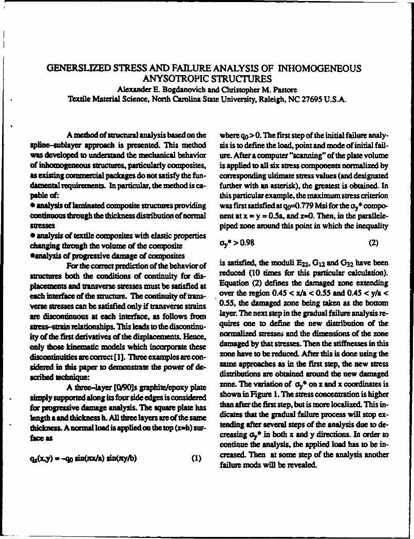
Flg. 1. Mmhmim of do .mmnalruad s a"ms z com m at thicknesses and fiber orientation along the x-axis in-o•a y=05&. (a) d dong xcoaoliuait aym0.. xmO (b) for
ate =&mdagd p1m (cum I) ad dhe damad pla W23,4) wi the top and bottom layers and along the y-axis in the3 diffam diodudoun medhis middle layer. Some results for the case of ransverse
A double box beam spar, exhibiting quasi- loading (1) are presented in Figure 3. It is seen thatunbalanced behavior was considered. It exhibits twist- longitudinal normal stress or suffers discontinuitiesbend coupling without extension-shear coupling. Both at the interfaces between 0 and 90 degree layers,experimental and analytical results have been obtained while the ransverse stresses T and oz don't showfor twistibend ratio of the spar for different reinforce- any visible discontinuities.ment angles. The geometry of the spar was as follows: a a b=900mm, b=46mm, h=48rmm, d= - mm.Theelastic i _ 0.properties of the Uniweave fabric composite ae: El -="_,,q128 GPa, Et - 12.l GPa, vu - 0.2 6, v-02G-. 6 = 02 " =OGa, and Gtt 5.01 GPa. The analytical and experimen- --
tal data awe compared in Figure 2. The analysis was per- -3
formed for the length-to-wall thickness ratio 150 _-T ..(insteadof900),torucethenumberofdegreesoffree-domenmployed, while operating at the maximumaccept- -10.5 1 0able element aspect ratio. Despite this simlftio of 0 1 0the mOdel the results match well to the experimental qdata. Not only are the general trends the same, but also 2 - X=o
twhiuwden .... X"A0ado 1.5- -
1.0 -,uay----Mt•awdm -1 2E
O.5 --- m - "0 0.5 1- - - Ft 3. iaim= of o, (a), % (b). =ad a (c) alog z for0 ,a three.layer cantiever plate under vuzveme loud
n~infremmeat--0.5- - - ie R
0 20 40 G go 8. Dogdaovih A.E. (1991). Spnn Punt Aided Anlysis2 2. Ainlytimd ad paim dam for die iwAImd of n ,mo enoI's -Matmias md Structre. Bse•in-HdMel-
=ndo a tk varkms renabdmmuat wagles of e box beam aper berg-New Yodrk Sp*W-ger-Wla, 1992, pp. 355-382
Rate Effects in Composite Materials
Wesley CantwellPolymers Laboratory, EPFL, Lausanne, Switzerland.
Fiber reinforced composites are presently of matrix mechanical properties. The nominal
being used in a wide range of engineering thickness of the molded panels was 2mm.
structures susceptible to some form of high Single edge notch bend (SENB) specimens
speed or dynamic loading. To date, very few having dimensions 14.5x58mm x thickness
systematic studies have been undertaken to were then cut from the panels using a
assess the rate sensitive fracture properties of diamond slitting wheel. Notches were thenfibrous composites and a detailed machined at the mid-span using a rotating saw
understanding of these materials response to blade. The notches were then sharpened by
rapid loading is still lacking. Welsh and sliding a fresh razor blade over the tip region.
Harding (1) used the split Hopkinson bar test The specimens were supported on two
to characterize the rate-dependency of the cylindrical rollers positioned 58mm apart and
tensile strength and modulus of a number of loaded at their mid-points directly above thelong fiber reinforced systems. Other workers notch. Tests using crosshead speeds between
(2,3) have used the double cantilever beam 0.1 and 100mm/min were conducted on an
test to study the influence of loading rate the Instron 1122 machine whereas impact testingon interlaminar fracture toughness of was undertaken using an instrumented drop-
thermosetting and thermoplastic-based weight tower. Material toughness was
composite materials, characterized by determining Kc and
In this study a fracture mechanics-type measuring a work of fracture Wf by simply
specimen geometry has been used to study the dividing the energy dissipated by the fracture
influence of loading rate on material area.
toughness and energy absorption. Tests have
been undertaken on a wide range of chopped 4
strand mat composites enabling the influence
of matrix properties on fracture toughness tobe studied in detail. Finally, the relationship
between the measured toughness of the
material and it's resistance to impact
perforation was examined.
The panels were manufactured by a hand lay- -
up technique involving impregnating three E- Fig. 1. Damage zone in a fractured CSM
glass fiber mats (300g/m 2 ) with either an SENB specimen tested at 1mm/minute.epoxy-based vinyl ester resin or a polyester A typical damage zone corresponding to a
resin. Twelve commercially available resins fractured CM specimen tested at lmm/min. is
were studied in order to have the widest range shown in Fig. 1. It is clear that energy has
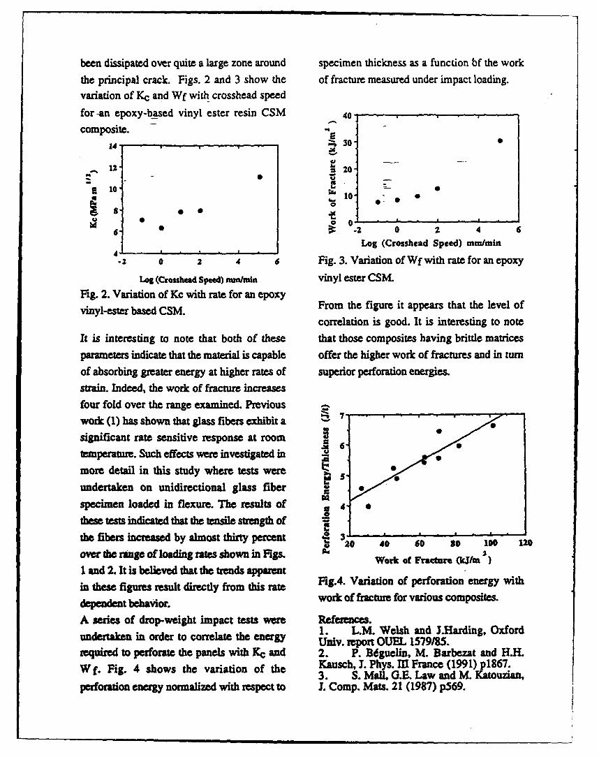
been dissipated over quite a large zone around specimen thickness as a function bf the work
the principal crack. Figs. 2 and 3 show the of fracture measured under impact loading.
variation of Kc and Wf with crosshead speed
for -an epoxy-based vinyl ester resin CSM 40- -
composite.
14 " 30-
-, 12- 20,
10
006- -2 0 2 4 6
Log (Crosshead Speed) mm/win4"
.2 o 2 4 6 Fig. 3. Variation of Wf with rate for an epoxy
Leg (Crosshead Speed) mm/miin vinyl ester CSM.
Fig. 2. Variation of Kc with rate for an epoxy
vinyl-ester based CSM. From the figure it appears that the level ofcorrelation is good. It is interesting to note
It is interesting to note that both of these that those composites having brittle matrices
parameters indicate that the material is capable offer the higher work of fractures and in turn
of absorbing greater energy at higher rates of superior perforation energies.
strain. Indeed, the work of fracture increases
four fold over the range examined. Previous
work (1) has shown that glass fibers exhibit a 7-
significant rate sensitive response at room
temperature. Such effects were investigated in .L
more detail in this study where tests were . -
undertaken on unidirectional glass fiber
specimen loaded in flexure. The results of 4 o
these tests indicated that the tensile strength of
the fibers increased by almost thirty percent 31 220 40 60 s0 100 12
over the range of loading rates shown in Figs. W JWork oC Fracture (kUm )1 and 2. It is believed that the trends apparentin these figures result directly from this r Fig.4. Variation of perforation energy with
dependent behavior. work of fracture for various composites.
A series of drop-weight impact tests were References.
undertaken in order to correlate the energy 1. L.M. Welsh and J.Harding, OxfordUniv. report OUEL 1579/85.
required to perforate the panels with KC and 2. P. Bdguelin, M. Barbezat and H.H.
W f. Fig. 4 shows the variation of the Kausch, J. Phys. MI France (1991) p18 6 7 .3. S. Mall. G.E. Law and M. Katouzian,
perforation energy normalized with respect to L Comp. Mats. 21 (1987) p569.
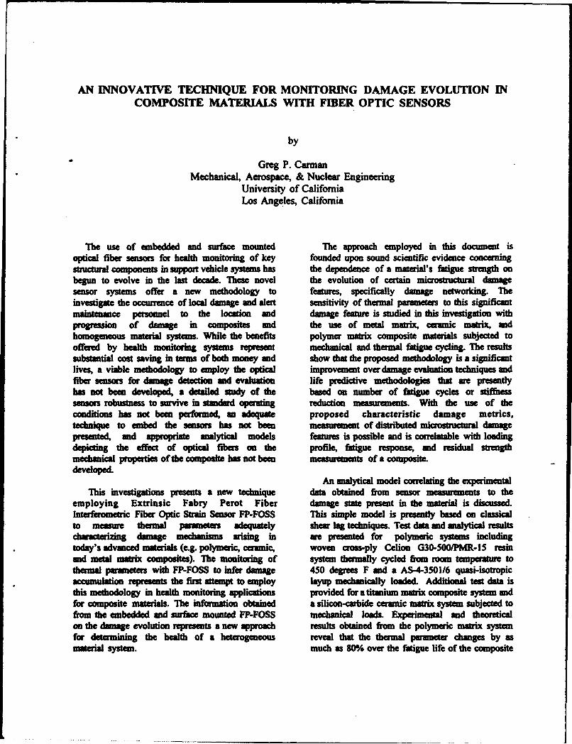
AN INNOVATIVE TECHNIQUE FOR MONITORING DAMAGE EVOLUTION INCOMPOSITE MATERIALS WITH FIBER OPTIC SENSORS
by
Greg P. CarmanMechanical, Aerospace, & Nuclear Engineering
University of CaliforniaLos Angeles, California
The use of embedded and surface mounted The approach employed in this document isoptical fiber sensors for health monitoring of key founded upon sound scientific evidence concerningstructural components in support vehicle systems has the dependence of a material's fatigue strength onbegun to evolve in the last decade. 1hese novel the evolution of certain miarstructural damagesensor systems offer a new methodology to features, specifically damage networking. Theinvestigate the occurrence of local damage and alert sensitivity of thermal parameters to this significantmaintennce personnel to the location and damage feature is studied in this investigation withprogression of damage in composites and the use of metal matrix, ceramic matrix, andhomogeneous material systems. While the benefits polymer matrix composite materials subjected tooffered by health monitoring systems represent mechanical and thermal fatigue cycling. The resultssubstantial cost saving in terms of both money and show that the proposed methodology is a significantlives, a viable methodology to employ the optical improvement over damage evaluation techniques andfiber sensors for damage detection and evaluation life predictive methodologies that are presentlyhas not been developed, a detailed study of the based on number of fatigue cycles or stiffnesssensors robustness to survive in standard operating reduction measurements. With the use of theconditions has not been performed, an adequate proposed characteristic damage metrics,technique to embed the sensors has not been measurement of distributed miacitrutr damagepresented, and appropriate analytical models features is possible and is correlatable with loadingdepicting the effect of optical fibers on the profile, fatigue response, and residual strengthmechanical properties of the composite has not been mts of a composite.devgloped.
An analytical model correlating the experimentalThis investigations presents a new technique data obtained from sensor measurements to the
employing Extrinsic Fabry Perot Fiber damage state present in the material is discussed.Interferometric Fiber Optic Strain Sensor FP-FOSS This simple model is presently based on classicalto measur thermal parameters adequately shear lag techniques. Test data and analytical resultscharacterizing damage mechanisms arising in are presented for polymeric systems includingtoday's advanced materials (e.g. polymeric, ceramic, woven cross-ply Celion G30-500/PMR-15 resinand metal matrix composites). The monitoring of system thermally cycled from room temperature tothermal parameters with FP-FOSS to infer damage 450 degrees F and a AS-4-3501/6 quasi-isotropicaccumulation represents the first attempt to employ layup mechanically loaded. Additional test data isthis methodology in health monitoring applications provided for a titanium matrix composite system andfor composite materials. The information obtained a silicon-carbide ceramic matrix system subjected tofrom the embedded and surface mounted FP-FOSS mechanical loads. Experimental and theoreticalon the damage evolution represents a new approach results obtained from the polymeric matrix systemfor determining the health of a heterogeneous reveal that the thermal paraneter changes by asmaterial system. much as 80% over the fatigue life of the composite
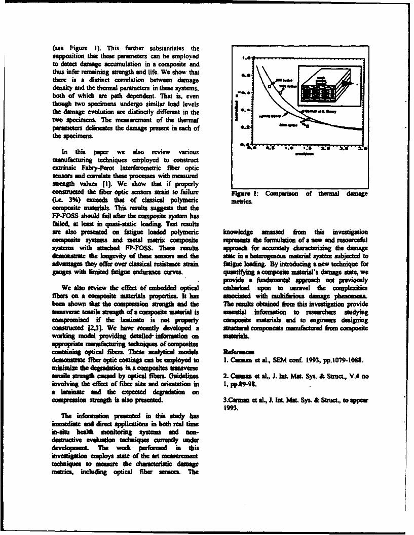
(see Figure 1). This further substantiates thesupposition that these parameters can be employed----to detect damage accumulation in a composite andthus infer remaining strength and life. We show that e.there is a distinct correlation between damagedensity and the thermal parameters in these systems,both of which are path dependent. That is, eventhough two specimens undergo similar load levels
the damage evolution are distinctly different in the sowtwo specimens. T'he measurement of the thermal " "parameters delineates the damage present in each of 0.2 a~a
the specimens.
In this paper we also review variousmanufacturing techniques employed to constructextrinsic Fabry-Perot Interferometric fiber opticsensors and correlate these processes with measuredstrength values [1]. We show that if properlyconstnrcted the fiber optic sensors strain to failure Figure 1: Comparison of thermal damage(i.e. 3%) exceeds that of classical polymeric metrics.composite mataials. This results suggests that theFP-FOSS should fail after the composite systm hasfailed, at least in quasi-static loading. Test remstsare also presented on fatigue loaded polymeric knowledge anassed from this investigationcomposite systems and metal matrix composite represents the formulation of a new and resourcefulsystems with attached FP-FOSS. These results ap1roh for accurately characterizing the damagedemontrate the longevity of these sensors and the state in a heterogenous material system subjected toadvantages they offer over classical resistance strain fatigue loading. By introducing a new technique forgauges with limited fatigue endurance curves. quantifying a composite material's damage state, we
provde a fumdamental approac not previouslyWe also review the effect of embedded optical embuied upon to unravel the complexities
fibers on a composite materials properties. It has usocited with multirious damage phenomena.been shown that the compression strength and the The results obtained from this investigation providetransver tensie strength of a composite material is essential information to resarchers studyingmpromised if the laminate is not properly composite materil and to engineers designing
constrce [2,3]. We have recently developed a ntrutural components manufactured fion compositeworking model providing detailed- information on materials.apprpiate manufacturing techniques of compositescontaining optical fibers. These maalytical models Remfedemonsrat fiber optic coatings can be employed to I. Carman et al., SEM conf. 1993, pp.1079-1088.minimize the degradation in a composites transversetensile strength caamed by optical fibers. Guidelinmes 2. Cauman et al., J. Int. Mat. Sys. & Struct., V.4 noinvolving the effect of fiber size and mientation in 1, pp.i9-98.a laminate and the expected degradation oncomapresio strength is also prsented. 3.Cuman et al., J. Int. Mat. Sys. & Stru•, to appema
1993.
The nihm om presented in this study hasimmediate and direct applications in both real timein-itu health monitoring system and non-destructive evaluon techniques currently underd The work performed in thisinvetigatio employs state of the art Measurementtechniques to measure the cwracteristic domagemetrics, including optical fiber sensors. The
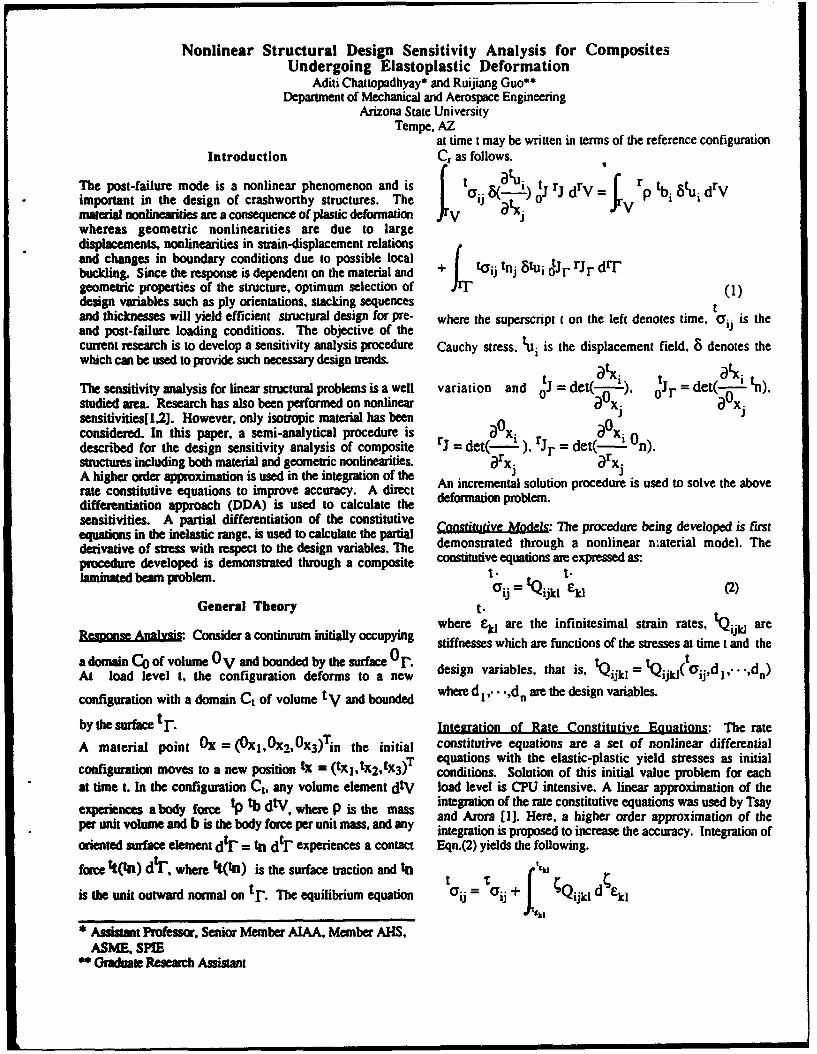
Nonlinear Structural Design Sensitivity Analysis for CompositesUndergoing Elastoplastic Deformation
Aditi Chattopadhyay* and Ruijiang Guo**Department of Mechanical and Aerospace Engineering
Arizona State UniversityTempe, AZ
at time t may be written in terms of the reference configurationIntroduction Cr as follows.
The post-failure mode is a nonlinear phenomenon and is t tui t rjrV r Simportant in the design of crashworthy structures. The Ci •(-) 0J J d V P tbi rma nonlinearities are a consequence of plastic deformation IV IVwhereas geometric nonlinearities are due to largedisplacements, nonlinearities in strain-displacement relationsand changes in boundary conditions due to possible local~ r- tioJ ~-dlbuckling. Since the response is dependent on the material and + toij tnj
geometric properties of the structure, optimum selection of (1)design variables such as ply orientations, stacking sequences tand thicknesses will yield efficient structural design for pre- where the superscript I on the left denotes time, (Y is theand post-failure loading conditions. The objective of thecurrent research is to develop a sensitivity analysis procedure Cauchy stress, tui is the displacement field. 8 denotes thewhich can be used to provide such necessary design trends. x ti
t = de(-.', r = det(-•..! tn).The sensitivity analysis for linear structural problems is a well variation and 0J det(- ) oJ=studied area. Research has also been performed on nonlinear a xj xsensitivities[1,2]. However, only isotropic material has beenconsidered. In this paper, a semi-analytical procedure is aOx ( Odescribed for the design sensitivity analysis of composite rj = det(- 2 ), rjr = det - n).structures including both material and geometric nonlinearities. rx. arx.A higher order approximation is used in the integration of therate constitutive equations to improve accuracy. A direct An incremental solution procedure is used to solve the abovedifferentiation approach (DDA) is used to calculate the deformation problem.sensitivities. A partial differentiation of the constitutiveequations in the inelastic range. is used to calculate the partial donstratied Moug The procedare being developed is firstderivative of stress with respect to the design variables. The demonstrated through a nonlinear naterial model. Theprocedure developed is demonstrated through a composite constitutive equations are expressed as:
laminated beam problem. t. t.=ij '- tQijkl k(2)
General Theory t.Cywhere k are the infinitesimal strain rates, tQijid are
a dom ,Bain Qofv Consider a continuum initially occupying stiffnesses which are functions of the stresses at time t and theadomain Co of volume O V and bounded by the surface O deinvribetht1.= Q ~ ~ n
At load level t, the configuration deforms to a new ijkl = jkl p
configuration with a domain Ct of volume tV and bounded where d 1.. "'dn are the design variables.
by the surface t r. Intearation of Rate Constitutive Eouations: The rate
A material point 0X = (0xl,0x2 ,0x 3)Tin the initial constitutive equations are a set of nonlinear differentialequations with the elastic-plastic yield stresses as initial
configuration moves to a new position tX = (tXl,tx2 ,tx 3)T conditions. Solution of this initial value problem for eachat time t. In the configuration Ct, any volume element dtV load level is CPU intensive. A linear approximation of the
em t where P is the mass integration of the rate constitutive equations was used by Tsayexperiences a body force tp ms dtVan and Arora [1]. Here, a higher order approximation of theper unit volume and b is the body forceer r unit mass, and any integration is proposed to increase the accuracy. Integration of
oriented surface element dtr = tn dtI experiences a contact Eqn.(2) yields the following.
fore tt(tn) dtr" where tt(tn) is the surface traction and tit "ik l k
is the unit outward normal on tr. The equilibrium equation Uij = ij IijlkI
* Assistant Professor, Senior Member AIAA. Member AHS,
ASME, SPIE* Graduate Research Assistant
| wMM
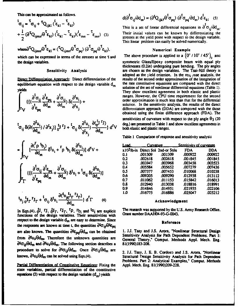
This can be approximated as follows. t oi/adm)= (ao: :l/at ( at=' I (a jk/ pq) O pq/ m) d£kl(5
aij oij + TQijkl (t.kl - Ekl) This is a set of linear differential equations in a tii/a-dmI-(TQ E t E Tkl - £mkl)(t - Ern) (3) Their initial values can be known by differentiating the+2 mnijm kl mn stresses at the yield point with respect to the design variable.
This linear problem can easily be solved numerically.
wheneaQijmn0'* Ekl = ( Qijmn/a pq) (a pq/ Ekl), Numerical Example
which can be expressed in terms of the stresses at time T and The above procedure is applied to a (0" / 10" / 45")2 anti
the design variables, symmetric Glass/Epoxy composite beam with equal plythicknesses (0.2in) undergoing pure bending. The ply angles
Sensitivity Analysis are chosen as the design variables. The Tsai-Hill theory isadopted as the yield criterion. In the resi inse analysis, the
Direct Differentiation Anmroach: Direct differentiation of the results of the second order approximation of the integration ofequilibrium equation with respect to the design variable dm the rate constitutive equations are compared with the directyd solution of the set of nonlinear differential equations (Table 0).
yelds They show excellent agreement in both elastic and plastic(t ai" at n ranges. However. the CPU time requirement for the second
ET +[(ZA..a.-C+ 1J order approximation is much less than that for the differentialI { t adm " 'm a( solution. In the sensitivity analysis, the results of the direct
J'V mdifferentiation approach (DDA) are compared with the thoseobtained using the finite difference approach (FDA). The
au ~t rp sensitivities of curvature with respect to the ply angle 03 (20t atu( ) ( r) deg.) are presented in Table I and show excellent agreements in
A) t r+ dr7 both elastic and plastic ranges.Table I Comparison of response and sensitivity analysis
rv[ ) +r Iu Load Curvature Sensitivity of curvature8tui + rp ti drV + xl05lb-in Direct Sol 2nd-or Solu FDA DDA
m 0.1 .001309 .001309 .000922 .0009220.2 .002618 .002618 .001845 .0018450.3 .003947 .003968 .003458 .003523
S. t.t E a t'.) t a" 0.4 .005584 .005652 .007279 .007436,,-Xni+ •egj ~i]0.5 .007377 .007453 .010068 .010238
iI n 0.6 .009205 .009290 .012938 .013112a ev 0.7 .011062 .011153 .015842 .016013
0.8 .012940 .013038 .018816 .0189910.9 .014846 .014951 .021935 .022106
t (n r) 1.0 .016775 .016886 .025047 .025212
tnj OJr Jr + Oij 8 1Ui " 1J d dr (4) Acknowledgment
In Eqn.(4). AJ. rj, Jr. rJr, rp. rbi and tnj are explicit The research was supported by the U.S. Army Research Office.functions of the design variables. Their sensitivities with Grant number DAAH04-93-G-0043.
respect to the design variable dm are easy to determine. Sincethe responses are known at time t, the quantities atijatEq Reference
awe also known. The quantities akp/Wm can be obtained 1. J.. Tsay and J.S. Arora. "Nonlinear Structural DesignSensitivity Analysis for Path Dependent Problems. Part 1:from atu'adm. Therefore the unknown quantities are General Theory," Comput. Methods Appl. Mech. Eag.
atcij/&dm and atu'/lm. The following section describes a 81(1990)183-208.
procedure to solve for ataiyaclm. Once atai/adm are 2. JJ. Tsay, J. E. B. Cordoso and J.S. Arora. 'Nonlinear
known, atuifd% can be solved using Eqn.(4). Structural Design Sensitivity Analysis for Path DependentProblems. Part 2: Analytical Examples," Comput. Methods
Partial Differentiation of Constitutive Euations" Fixing the Appl. Mech. Eng. 81(1990)209-228.state variables, partial differentiation of the constitutiveequations (2) with respect to the design variable (din) yields
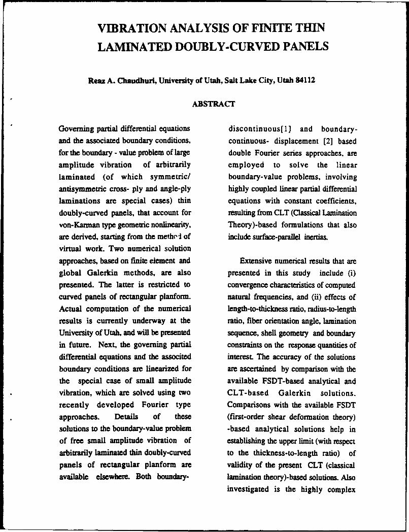
VIBRATION ANALYSIS OF FINITE THIN
LAMINATED DOUBLY-CURVED PANELS
Reaz A. Chaudhuri, University of Utah, Salt Lake City, Utah 84112
ABSTRACT
Governing partial differential equations discontinuous[ I] and boundary-
and the associated boundary conditions, continuous- displacement [2] based
for the boundary - value problem of large double Fourier series approaches, are
amplitude vibration of arbitrarily employed to solve the linear
laminated (of which symmetric/ boundary-value problems, involving
antisymmetric cross- ply and angle-ply highly coupled linear partial differential
laminations are special cases) thin equations with constant coefficients,
doubly-curved panels, that account for resulting from CLT (Classical Lamination
von-Karman type geometric nonlinearity, Theory)-based formulations that also
are derived, starting from the metheI of include surface-parallel inertias.
virtual work. Two numerical solution
approaches, based on finite element and Extensive numerical results that are
global Galerkin methods, are also presented in this study include (i)
presented. The latter is restricted to convergence characteristics of computed
curved panels of rectangular planform. natural frequencies, and (ii) effects of
Actual computation of the numerical length-to-thickness ratio, radius-to-length
results is currently underway at the ratio, fiber orientation angle, lamination
University of Utah, and will be presented sequence, shell geometry and boundary
in future. Next, the governing partial constraints on the response quantities of
differential equations and the associted interest. The accuracy of the solutions
boundary conditions are linearized for are ascertained by comparison with the
the special case of small amplitude available FSDT-based analytical and
vibration, which are solved using two CLT-based Galerkin solutions.
recently developed Fourier type Comparisons with the available FSDT
approaches. Details of these (first-order shear deformation theory)
solutions to the boundary-value problem -based analytical solutions help inof free small amplitude vibration of establishing the upper limit (with respect
arbitrarily laminated thin doubly-curved to the thickness-to-length ratio) of
panels of rectangular planform are validity of the present CLT (classicalavailable elsewhere. Both boundary- lamination theory)-based solutions. Also
investigated is the highly complex
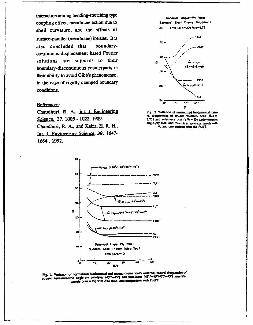
interaction among bending-stretching type Somencal AV,-f P ,w,
coupling effect, membrane action due to Sanders Shell Theory (Modifiedl
shell curvature, and the effects of 34 - ab;ah-2o;R/a-5.73
surface-parallel (membrane) inertias. It is 32-
also concluded that boundary- -- t
continuous-displacement based Fourier /030 ""...
solutions are superior to their - .
boundary-discontinuous counterparts in26
their ability to avoid Gibb's phenomenon,
in the case of rigidly clamped boundary
conditions."CLt
24References: 0. 15. 30. 45-
8
Chaudhuri, R. A., InL J. Engineering Fig. 2 Varation of nomalized fundanetal m au-ral frequenc:es of squma reauvewy deep RI-.
Scienc 27, 1005 - 1022, 1989. 5.73) and relatively thin (4/h - 20) anyanac•, cangi-01 **O-and four-layer sphberical panel with
Chaudhuri, R. A., and Kabir, H. R. H., Wo mpansono.le with the FSDT.
JUt. . Engineering Science, 30, 1647-
1664,1992.
40 -
35- _ FSDT
.....- CLT
S/ •~--, , T
30 -
CLT
20-
Soneiecal Angle-Ply PanelSanders* Shell Theory (Modmfiiidi
a-b ;a0/h -10
0 10 20 30 0 s
4/0
Fig. 1. Variation of normalized fildamewlm sad --emi (masmitaily ordered) natural frequeCies" Ofsqmanaisymmtum angkle-py two-lae (45"f-41) md ftur4awu (45/-45'/4r/-4T) sherica
panels (ajh - 10) wit RI. rats, and compasuo with FSDT.
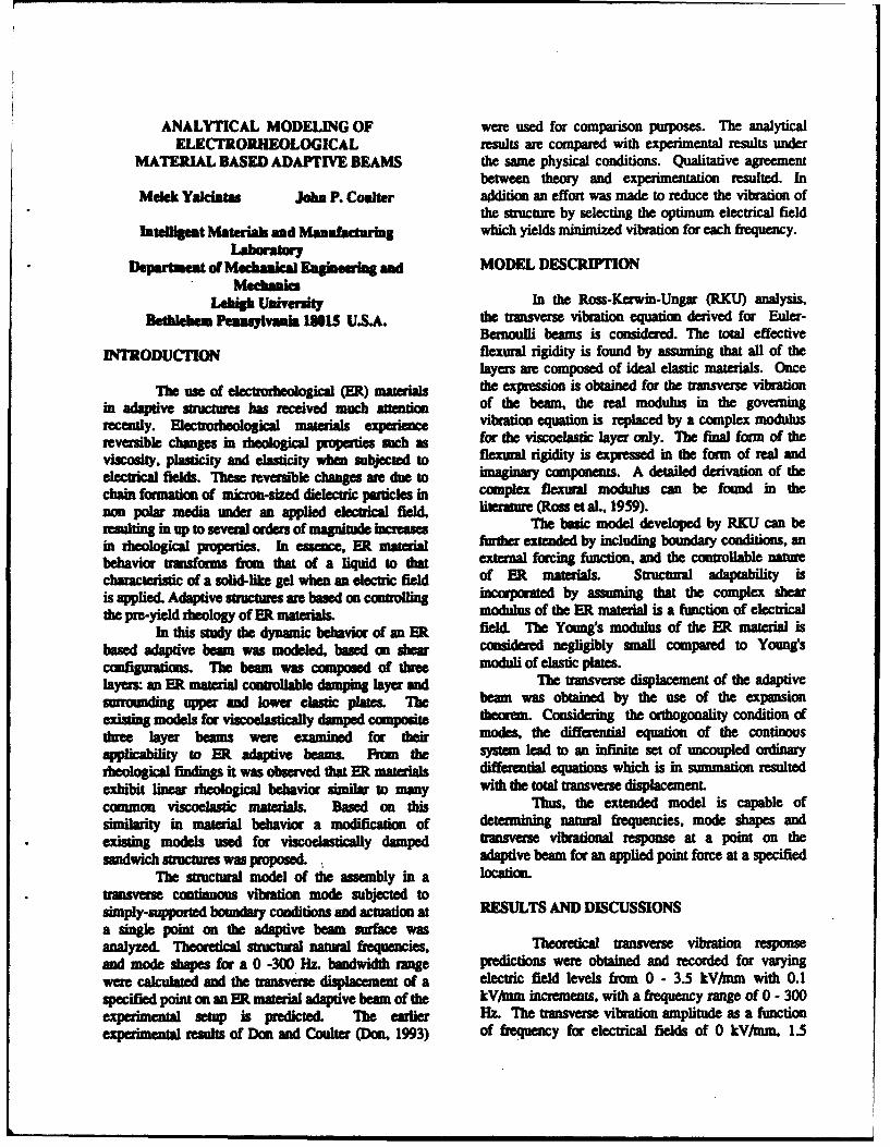
ANALYTICAL MODELING OF were used for comparison purposes. The analyticalELECTROR, EOLOGICAL results are compared with experimental results under
MATERIAL BASED ADAPTIVE BEAMS the same physical conditions. Qualitative agreementbetween theory and experimentation resulted. In
Melek Yaklintes John P. Couler addition an effort was made to reduce the vibration ofthe structure by selecting the optimum electrical field
Iatlligeimt Materiak and Maufacturi which yields minimized vibration for each frequency.Labwaorym
Departmen of Mecanical Ehaelnwueua and MODEL DESCRIPTIONMeclamkis
LOW61 Univsity In the Ross-Kerwin-Ungar (RKU) analysis,Bethlehm P. $vmk I10S U.S.A. the trwisverse vibration equation derived for Euler-
Bernoulli beams is conidered. The total effectiveINTRODUCTION flexural rigidity is found by assuming that all of the
layers are composed of ideal elastic materials. OnceThe use of electrorheological (ER) materials the expression is obtained for the transverse vibration
in adaptive structures has received much auion of the beam, the real modulus in the governingrecently. Electrorheological materials experience vibration equation is replaced by a complex modulusreversible changes in theological properties such afor the viscoelastic layer only. The final form of theviscosity, plasticity and elasticity when subjected to flexural rigidity is expresse in the form of real andelectrical fields. These reversibl changes are due to imaginary components. A detailed derivation of the
chain formation of mon-sized dielectric particles in complex flexural modulus can be found in the
non polar media under an applied electrical field, literature (Ross et •L., 1959).resulting in up to several orders of mgnit&incrases The basic model developed by RKU can bein rheological properties. In essence, ER mtrial further extended by including boundary conditions, anbehavior transforms from that of a liquid to that external forcing function, and the controllable naturecharacteristic of a solid-like gel when an electric field of ER materials. Suuctural adaptability is
is applied. Adaptive structures ae based on corrotlingc by assuming that the complex shearthe pre-yield •heology of ER materials. modulus of the ER material is a function of electrical
In this study the dynamic behavior of an ER field. The Young's modulus of the ER material isbased adaptive beam was modeled, based on shear considered negligibly small compared to Young'scofiguratios. The beam was composed of dtree moduli of elastic plates.layers an ER material controllable damping layer and The transverse displacement of the adaptivesmuounding upper and lower elastic plates. The beam was obtained by the use of the expansionexisting models for viscoelastically damped composite theorem. Considering the orthogonality condition ofthree layer beams were examined for their mode, the differential equation of the continousapplicability to ER adaptive beams. From the system lead to an infinite set of uncoupled ordinarytheological findings it was observed that ER materials differential equations which is in summation resultedexhibit linear rheologia behavior similar to many with the total transverse displacement.common viscoelastic materials. Based on tis Thus, the extended model is capable ofsimilarity in material behavior a modification of determining natural frequencies, mode shapes andexisting models used for viscoelastically damped transverse vibrational response at a point on thesandwich smuctw s was proposed. adaptive beam for an applied point force at a specified
The structural model of the assembly in a location.uisverne continuous vibration mode subjected to
simply-supported boundary conditions and actuation at RESULTS AND DISCUSSIONSa single point on the adaptive beam surface wasanalyzed. Theoretical suctural natural frquencies, Theoretical transverse vibration responseand mode shapes for a 0 -300 Hz. bandwidth range predictions were obtained and recorded for varyingwere calculated and the transverse displacement of a electric field levels from 0 - 3.5 kV/nm with 0.1specified point on an ER material adaptive beam of the kV/mm increments, with a frequency range of 0 - 300experimenta setup is predicted. The earlier Hz. The transverse vibration amplitude as a functionexperimental results of Don and Coulter (Don, 1993) of frequency for electrical fields of 0 kVMum, 1.5
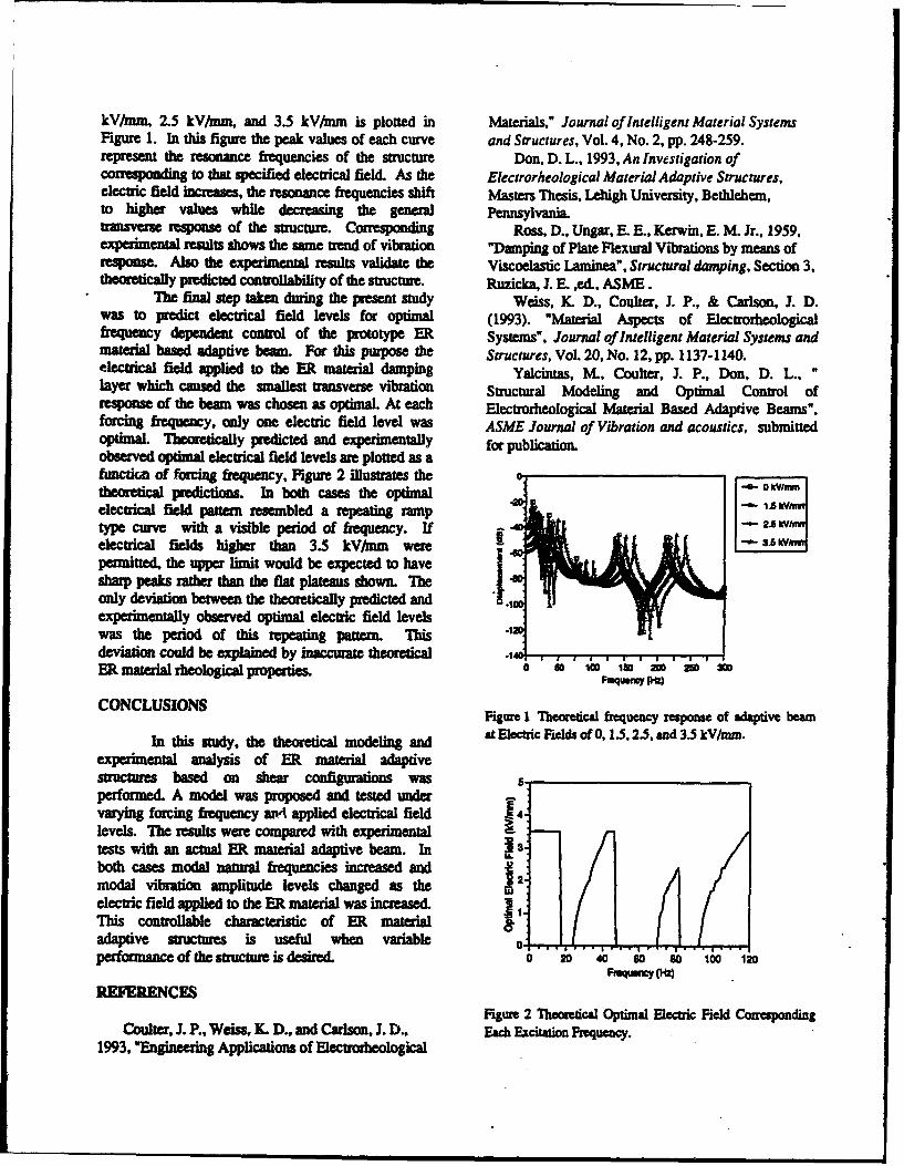
kVlmm, 2.5 kV/mm, and 3.5 kV/mm is plotted in Materials," Journal of Intelligent Material SystemsFigure 1. In this figure the peak values of each curve and Structures, Vol. 4, No. 2, pp. 248-259.represent the resonance frequencies of the structure Don, D. L., 1993, An Investigation ofcorresponding to that specified electrical field. As the Electrorheological Material Adaptive Structures,electric field increses, the resonance frequencies shift Masters Thesis, Lehigh University, Bethlehem,to higher values while decreasing the general Pennsylvania.transverse response of the structure. Corresponding Ross, D., Ungar, E. E., Kerwin, E. M. Jr., 1959,experimental results shows the same trend of vibration "Damping of Plate Flexural Vibrations by means ofresponse. Also the experimental results validate the Viscoelastic Laminea", Structural damping, Section 3,themically predicted controllability of the structure. Ruzicka, J. E. ,ed., ASME.
The final step taken during the present study Weiss, K. D., Coulter, J. P., & Carlson, J. D.was to predict electrical field levels for optimal (1993). "Material Aspects of Electrorheologicalfrequency dependent control of the prototype ER Systems", Journal of Intelligent Material Systems andmatrial based adaptive beau. For this purpose the Structures, Vol. 20, No. 12, pp. 1137-1140.electrical field applied to the ER material damping Yalcintas, IVL, Coulter, J. P., Don, D. L.,layer which caused the smallest transverse vibration Structural Modeling and Optimal Control ofresponse of the beam was chosen as optimal. At each Electrorheological Material Based Adaptive Beams",forcing frequency, only one electric field level was ASME Journal of Vibration and acoustics, submittedoptimaL Theomticaly predicted and experimentally for publication.observed optimal electrical field levels are plotted as afunction of frceing frequency, Figure 2 illustrates the G
theortical predictions. In both cases the optimalelectrical field patern resembled a repeating ramptype curve with a visible period of frequency. If " ., ..-electrical fields higher than 3.5 kV/mm were - 3 -- wIpermitted, the upper limit would be expected to have .1sharp Peaks rather than the flat plateau shown. Theonly deviation between the theoretically predicted and "0.1experimentally observed optimal electric field levelswas the period of this repeating pattern. Thisdeviation could be explained by inaccurate theoretical .11ER material teoloical prpes a 0 100 02 250 30
CONCLUSIONSFigure I Theoretical frequency response of adaptive beam
In this study, the theoretical modeling and at Electric Fields of 0, 1.5, 2.5, and 3.5 kV/mm.
experimental analysis of ER material adaptivestructmes based on shear configurations wasperformed. A model was proposed and tested undervarying forcing frequency ap.4 applied electrical field 14.
levels& The results were compared with experimentaltests with an actual ER material adaptive beam. In 3 1.both cases modal natural frequencies increased and "modal vibration amplitude levels changed as the relectric field applied to the ER material was increased IThis controllable characteristic of ER materialadaptive structures is useful when variable oL IPerformance of the structure is desired. o 20 4 0 8 0 2
Fwunoy (Hz)REFERENCES
Figure 2 Theoretical Optimal Electric Field CorrespondingCoulter, J. P., Weiss, K. D., and Carlson, J. D., Each Excitation Frequency.
1993, "Engineering Applications of Electrorheological
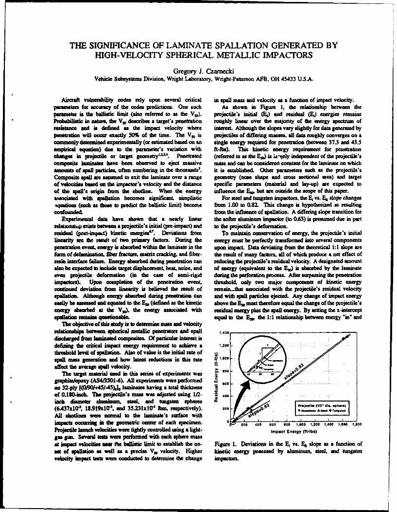
THE SIGNIFICANCE OF LAMINATE SPALLATION GENERATED BYHIGH-VELOCITY SPHERICAL METALLIC IMPACTORS
Gregory J. CzarneckiVehicle Subsystems Division, Wright Laboratory, Wright-Patterson AFB, OH 45433 USA.
Aircraft vulnerability codes rely upon several critical in spall mass and velocity as a function of impact velocity.parameters for accuracy of the codes predictions. One such As shown in Figure 1. the relationship between theparameter is the ballistic limit (also referred to as the V,0). projectile's initial (EO) and residual (E) energies remainsProbilistic in nature, the Vs describes a target's penetration roughly linear over the majority of the energy spectrum ofresistance and is defined as the impact velocity where interesL Although the dopes vary slightly for data generated bypenMration will occur exactly 50% of the time. The V,0 is projectiles of differing masses, all data roughly converges on acommonly determined experimentally (or estimated based on an single energy required for penetration (between 37.3 and 43.5empirical equation) due to the parameter's variation with ft-lbs). This kinetic energy requirement for penetrationchanges in projectile or target geometry'2 . Penetrated (referred to as dhe Es.) is !a- ely independent of the projectile'scomposite laminates have been observed to eject massive mass and can be considered constant for the laminate on whichamounts of qsall paticles, often numbering in the thousands'. it is established. Other parameters such as the projectile'sComposite spall ae assumed to exit the laminate over a range geometry (nose shape and cross sectional area) and targetof velocities based on the impactor's velocity and the distance specific parameters (material and lay-up) are expected toof the spell's origin from the shotline. When the energy influence the Era, but are outside the scope of this paper.aumociated with spallation becomes significant simplistic For steel and tungsten impactors, the E vs. ER slope changesAquatioe (such as those to predict the ballistic limit) become from 1.00 to 0.82. This change is hypothesized as resultingconfounded. from the influence of spallation. A differing slope transition for
Pxperimental data have shown that a nearly linear the softer aluminum impactor (to 0.63) is presumed due in partrelationskup exists between a projectile's initial (pre-impact) and to the projectile's deformation.residual (poss.impai) kinetic energies'. Deviations from To maintain conservation of energy, the projectile's initiallinearity are the result of two primary factors. During the energy must be perfectly transformed into several componentspenetration event, energy is absorbed within the laminate in the upon impacL Data deviating from the theoretical 1:1 slope areform ofdelamination, fiber hacture. matrix crackin& and fiber- the result of many factomrs, all of which produce a net effect ofresin interface failume. Energy absorbed during penetration can reducing the projectile's residual velocity. A designated amountalso be expected to include target displacement. heat, noise, and of energy (equivalent to the E) is absorbed by the laminateeven projectile deformation (in the case of semi-rigid during the perforation process. After surpassing the penetrationimpactors). Upon completion of the penetration event, threshold, only two major components of kinetic energycontinued deviation from linearity is believed the result of remain..that associated with the projectile's residual velocityspalation. Although energy absorbed during penetration can and with spill particles ejected. Any change of impact energyeasily be aisnsed and equated to the En (defined as the kinetc above the E, must therefore equal the change of the projectile'senergy absorbed at the Vs), the energy associated with residual energy plus the spall energy. By setting the x-interceptspailation rmains questionable, equal to the Ev. the 1:1 relationship between energy "in" and
The objective of this study is to determine mass and velocityrelaionships between spherical metallic peneftaors: and spall ,0dischaged from laminaed composites. Of particular interest isdefining the critical impact energy requirement to achieve a 1,200
threshold level of spallation. Also of value is the initial rate ofspel mas generation and how latent reductions in this rate 9 1.00oaffect the aveage spall velocity. 80
The target material used in this series of experiments wasg raphpoxy (AS4/3501-6) All experiments were performed goon 32-ply [(0/90/+45/-45)J] laminates having a total thickness "of O.180-inch. The projectile's m- was adjusted using 1f2- 400
inch diameter aluminuom steel and tungsten spherem(6.437x10', 18.919i10'. and 35.231x10"' Ibm, respectively). zooon.cil (rr d,,. sphere)
All shotlin e were norm al to the lam inate's surface with , " "l " " " ÷ A"".
pe ocurngi the geometric center of specimen. h200 0 0 0 1.000 1.200 1,.400 1,,00 1,00
Projecte v s wn tightly conrolled wng a ligh Impact Energy (ft-lbs)g-a Sun. Several tests wer performed with each sphere massat imnpact velocities nea the br lsti lmit to eslrish the on- Figur 1. Deviations in the A vs. ER slope as a function ofsd of spallation as well as a precise V,, velocity. Higher kinetic energy posessed by aluminum, steel, and tungstenvelocity impact tests were conducted to determine the change impactor
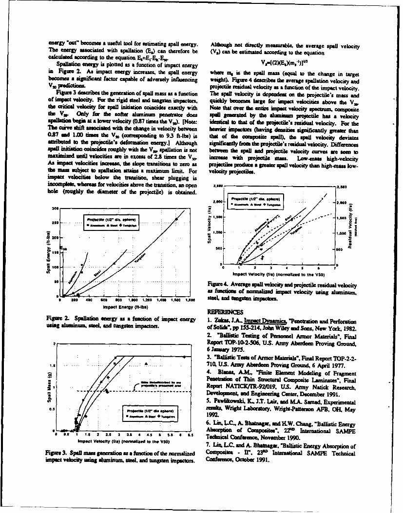
energy "out" becomes a useful tool for estimating spall energy. Although not directly mesrbe die average spell velocityThe energy assoiated with spllation (L,) can therefore be (Va) can be estimated according to the equationcalculated according to the equation, EszE,-rE _,VA2Eso.n3`J
Spaflation energy is plotted as a function of impact energyVsI2EX )win Figure 2. As impact energy increases, the spall energy where ms is the spell mass (equal to the change in targetbecomes a significant factor capable of adversely influencing weight). Figure 4 describes the average spallation velocity andVn preitions5. projectile residual velocity as a function of the impact velocity.
Figure 3 describes the generation of spall mass as a function T`he spall velocity is dependent on dhe projectile's mass andof impact velocity. For the rigid sael and tungsten impactors, quickly becomes large for impact velocities above dhe VSOthe critical velocity for spell initition, coincides exactly with Note that over the entire impact velocity spectumn, compositedue Va. Only for the softer alhlaintim penetrator does spell generated by the aluunmuin projectile has a velocityspallation begin at a lower velocity (0.87 times the Vs). (Note: idenitical lo tha of the projectile's residual velocity. For theThe ove shift associated with the change in velocity between heavrier impactors (having densities significantly greater than0.87 arid 1.00 times the VS, (corresponding to 9.3 ft-fin) is that of the composite spell), the spell velocity deviatesattributedl to the prjectile's deformation energy.] Although significanltly from the projectile's residual velocity. Differencesspall initiation coincides roughly with the V,, spallation is not between the spell and projectile velocity curves wre aow tomaxiniizmd until velocities wre int excess of 2.8 times the VS` increase: with projectile mas. Lo~w-mms high-velocityAs limpact velocities increase, the slope transitions to zero as projectiles produce a greater spell velocity tha high-masis low-the amas subject to spallation attains a maximum limit. For velocity projectiles.impact velocities below the transition, shear plugging isincomplele, whereas for velocities above the transition, an open 2.500: 2.560hole (roughly the diameter of the projectile) is obtained. Pfle[ l (112 -- *-& 2.000)
2.00W-,300 Z.
I,0 - Z~'i~~of-* . .' -- - - - 1.S00O
q2 0 0
0ý o IF -50IO S~ o
,, g 19 1 2 3 5 6W Impact Velocity (its) (normalized to the VSO)
so .. .. Figure 4. Average spell velocity and projectile residuial velocityasfunctions Of normalized impact velocity using aluminum,
0 200 400 G00 Goo 1.000 1,200 1,400 1.800 1.;00 stel, and tungsten impactors.Impact Energy (tt.Ibs) RFRN
Figure 2.. Spoliation energy as a function of impact energy 1. Zukas, JA., Imac "Penetration and11 Perforationusing aluminum, steel, and tungsten impactors. of Solig, pp 155-214, John, Wiley and Sons, New Yodr, 1962.
2. "Ballistic Testing of Peronmel Armor Materials", Final2,Report TOP-10-2-506,, U.S. Army Aberdeen Proving Ground,
6 January 1975.3. *B"Balstic Tests of Armor Materiask", Final Report TOP-2-2-
1.5...... .. 710, U.S. Armty Aberdeen Proving Groud, 6 April 1977.4. Bllmas, A.M, "Finite Element Modeling of FragmentPenetration of Thin Structural Composite Lamninates", Finali .. s~rnwa~wReport NAT1CK/rR-921019. U.S. Army Natick Research,
--- - ------ ----- -------- Development, and Engineering Center, December 1991.(A 5. PaWWwALko 4i Y., JLT. Lair, anid M.A. Samnad, Experimental
0.5 rolW (12-dieresults, Wright Laboratory, Wright-Pafterson AFB, OR~ Maya &a-A is. La t4.w, 92
6. Lint. LC., A. Bhatmaglr, and ILW. Chang, -Ballistic Energy0. we . .5228. . . Absorption of Composites". 22"0) Internationlal SAMPE0 0. . . .1445535663 Technical Conferenice, November 199.
Impact V.elocty (tIa) Inonnai~zed 1o the V50 7. Lin., LC. anld A. Blhanmagar, "Ballistic Energy Absorption ofFigure 3. Spell mms generation as a function of the normalized Composites - II', 23" International SAMPE Technicalimpact velocit using alluminum, steel and tungsten impactors. Coitfnumoe, October 1991.
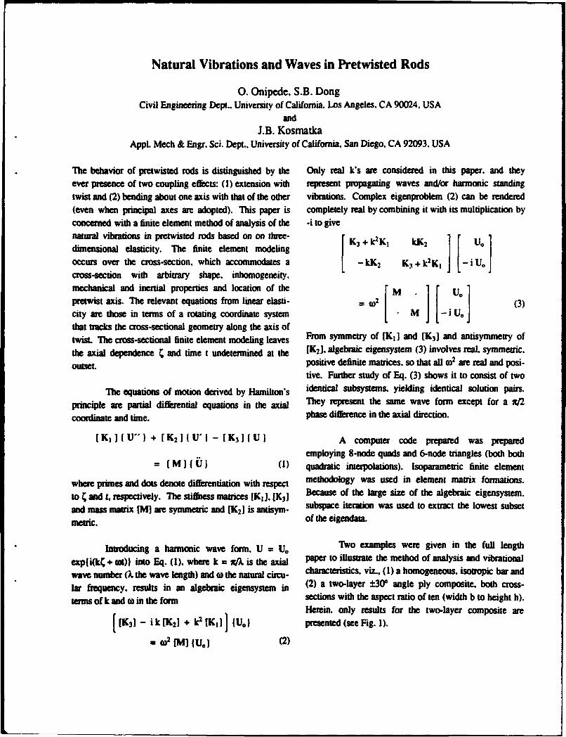
Natural Vibrations and Waves in Pretwisted Rods
0. Onipede. S.B. DongCivil Engineering Dept.. Universty of California. Los Angeles. CA 90024. USA
andJ.B. Kosmatka
Appl. Mech & Engr. Sci. Dept.. University of California. San Diego, CA 92093. USA
The behavior of pretwisted rods is distinguished by the Only real k's are considered in this paper. and theyever presence of two coupling effects: (1) extension with represent propagating waves and/or harmonic standing
twist and (2) bending about one axis with that of the other vibrations. Complex eigenproblem (2) can be rendered(even when principal axes are adopted). This paper is completely real by combining it with its multiplication byconcerned with a finite element method of analysis of the -i to givenatural vibrations in pretwisted rods based on on three- rK3 +1VK kK2 U.
dimensional elasticity. The finite element modelingoccurs over the cross-section, which accommodates a -kK 2 K3 + k2 Kt -i Uocross-section with arbitrary shape. inhomogeneity.
mechanical and inertial properties and location of the MUpretwist axis. The relevant equations from linear elasti- =o2 (3)
city are those in terms of a rotating coordinate system M _iU.that tracks the cross-sectional geometry along the axis oftwist. The cross-sectional finite element modeling leaves From symmetry of [KI] and [K3] and antisymmetry of
the axial dependence ý and time t undetermined at the [(K2]. algebraic eigensystem (3) involves real. symmetric.
outseL positive definite matrices, so that all 0) are real and posi-
tive. Further study of Eq. (3) shows it to consist of two
The equations of motion derived by Hamilton's identical subsystems, yielding identical solution pairs.
principle are partial differential equations in the axial They represent the same wave form except for a w/2
coordinate and time. phase difference in the axial direction.
[KI]IU-I + [K 2 ](U'I - [K 3 1IUI A computer code prepared was prepared
employing 8-node quads and 6-node triangles (both both
= [ M ] U (1) quadratic interpolations). Isoparametric finite element
where primes and dots denote differentiation with respect methodology was used in element matrix formations.
to 4 and t. respectively. The stiffness matrices [KI], [K 3) Because of the large size of the algebraic eigensystem.
and mass matrix [M] are symmetric and [(K2] is antisym- subspace iteration was used to extract the lowest subset
metric, of the eigendata.
Introducing a harmonic wave form. U = U, Two examples were given in the full length
expfi(kC + ot)) into Eq. (1). where k = x/ is the axial paper to illustrate the method of analysis and vibrational
wave number (X the wave length) and w the natural circu- characteristics, viz., (1) a homogeneous. isotropic bar and
lar frequency, results in an algebraic eigensystem in (2) a two-layer ±W30 angle ply composite. both cross-
terms of k and to in the form sections with the aspect ratio of ten (width b to height h).Herein. only results for the two-layer composite are
[(K3] - i k[K2] + k2KI) I U.) presented (see Fig. 1).
=2IM] 1U.) (2)
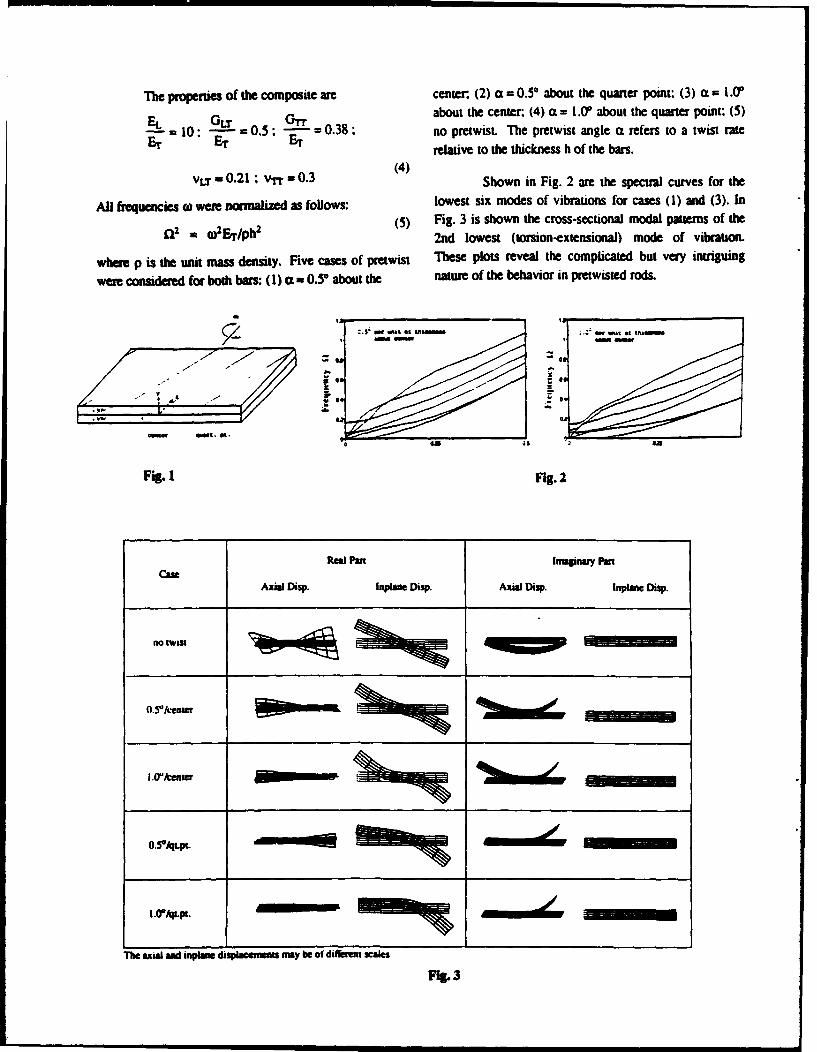
Te propeties of the composite are center. (2) a = 0.5" about the quarter point: (3) a: = I .0
EL GLT about the center (4) a = 1.(Ur about the quarter point: (5)S10: =0.5: �- = 0.38: no pretwist. The pretwist angle a refers to a twist rate
Br 10 ET - Er relative to the thickness h of the bars.
vLT a 0.21 : V-rr - 0.3 Shown in Fig. 2 are the spectral curves for the
All frequencies w were normalized as follows: lowest six modes of vibrations for cases (1) and (3). In
(5) Fig. 3 is shown the cross-sectional modal patterns of thea2 = o•Flph2 22nd lowest (torsion-extensional) mode of vibration.
where p is the unit mass density. Five cases of pretwist These plots reveal the complicated but very intiguing
were considered for both bars: (1) a = 0.5* about the nature of the behavior in pretwisted rods.
Rea Pa IJagnas P'
CaseAmial Disp. Inpiane Dasp. Aat Disp. Inpiane Disp.
no IwFit -
O.?a/qLpL -MMI1
IEEEIEEIEIL -
The aal and inpans dip cemen mnay be of dif iell scales
F%. 3
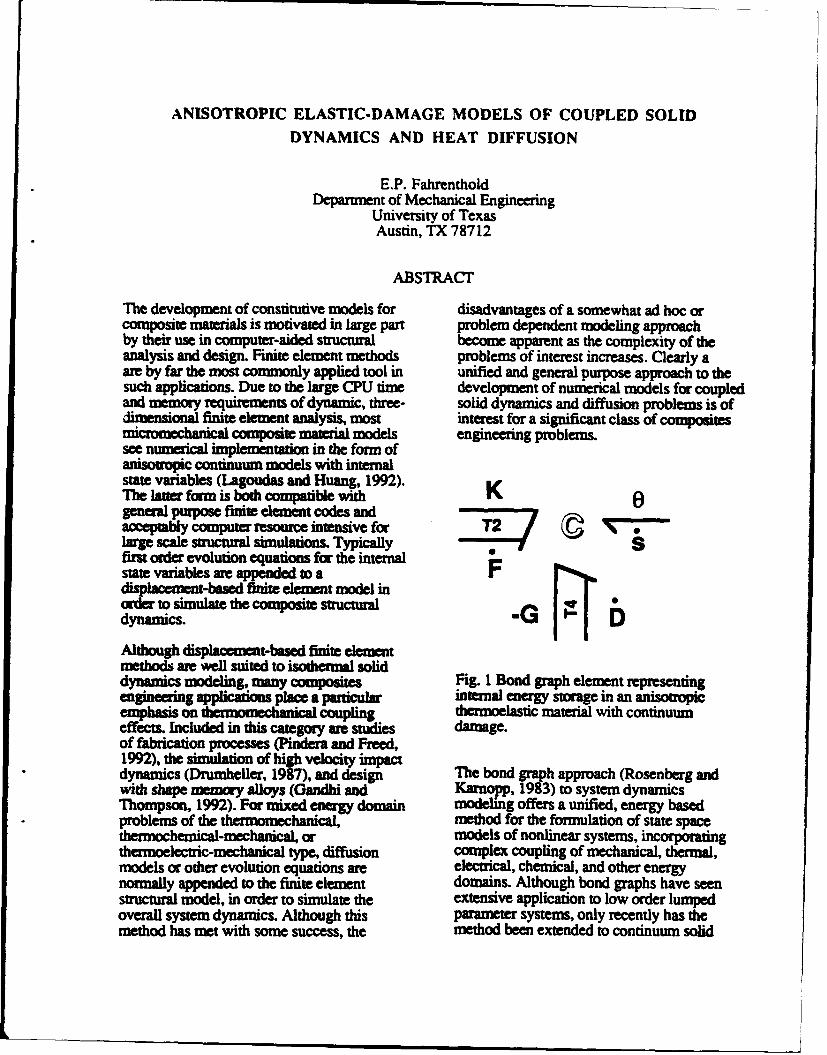
ANISOTROPIC ELASTIC-DAMAGE MODELS OF COUPLED SOLIDDYNAMICS AND HEAT DIFFUSION
E.P. FahrentholdDepartment of Mechanical Engineering
University of TexasAustin, TX 78712
ABSTRACT
The development of constitutive models for disadvantages of a somewhat ad hoc orcomposite materials is motivated in large part problem dependent modeling approachby their use in computer-aided structural become apparent as the complexity of theanalysis and design. Finite element methods problems of interest increases. Clearly aare by far the most commonly applied tool in unified and general purpose approach to thesuch applications. Due to the large CPU time development of numerical models for coupledand memory requirements of dynamic, three- solid dynamics and diffusion problems is ofdimensional finite element analysis, most interest for a significant class of compositesmicrmechanical composite material models engineering problems.see numerical implementation in the form ofanisoric continuum models with internalstate variables (Lagoudas and Huang, 1992).The later form is both comp ble with Kgeneral purpose finite element codes andacceptably computer resource intensive for Tlarge scale sctural simulations. Typicallyfirst order evolution equations for the internalstate variables are appended to adisplacement-based finite element model inorder to simulate the composite structuraldynamics. -GAlthough dispacement-based finite elementmethods are well suited to isothermal soliddynamics modeling, many composites Fig. 1 Bond graph element representingengineering applications place a particulr internal energy storage in anemphasis on emomechanical coupling thermoelastic material with continuumeffects. Included in this category are studies damage.of fabrication processes (Pindera and Freed,1992), the simulation of high velocity impactdynamics (Drumheiler, 1987), and design The bond gra1983)pto syst enamcwith shape memory alloys (Gandhi and Karnopp, 3) to system dynamicsThompson, 1992). For mixed domain modeling offers a unified, energy basedproblems of the thermomechanical method for the formulation of state spacethermochemical-mechanical, or models of nonlinear systems, incorporatingthermoelectric-mechanical type, diffusion complex coupling of mechanical, thermal,models or other evolution equations are electrical, chemical, and other energynormally appended to the finite element domains. Although bond graphs have seenstructural model, in order to simulate the extensive application to low order lumpedoverall system dynamics. Although this parameter systems, only recently has themethod has met with some success, the method been extended to continuum solid
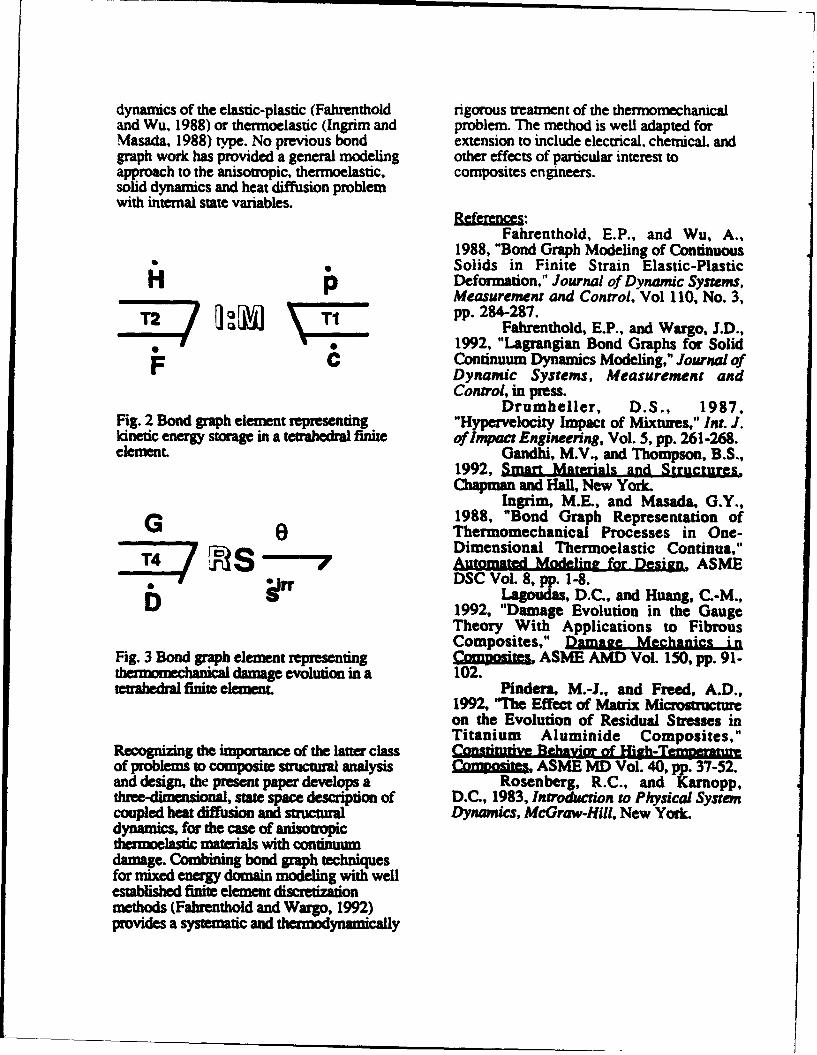
dynamics of the elastic-plastic (Fahrenthold rigorous treatment of the thermomechanicaland Wu, 1988) or thermoelastic (Ingrim and problem. The method is well adapted forMasada, 1988) type. No previous bond extension to include electrical, chemical, andgraph work has provided a general modeling other effects of particular interest toapproach to the anisow-opic, thermoelastic, composites engineers.solid dynamics and heat diffusion problemwith internal state variables. Referece~s:
Fahrenthold, E.P., and Wu, A.,1988, "Bond Graph Modeling of ContinuousSolids in Finite Strain Elastic-PlasticDeformation," Journal of Dynamic Systems,Measurement and Control, Vol 110, No. 3,
T2 T1pp. 284-287.Fahrenthold, E.P., and Wargo, J.D.,
1992, "Lagrangian Bond Graphs for SolidContinuum Dynamics Modeling," Journal ofDynamic Systems, Measurement andControl, in press.
Drumheller, D.S., 1987,Fig. 2 Bond graph element representing "Hypervelocity Impact of Mixtures," Int. J.kinetic energy storage in a tetrahedral finite of impact Engineering, Vol. 5, pp. 261-268.element. Gandhi, M.V., and Thompson, B.S.,
1992, Smart Materials and StructuresChapman and Hall, New York.
Ingrim, M.E., and Masada, G.Y.,1988, "Bond Graph Representation ofThermomechanical Processes in One-Dimensional Thermoelastic Continua,"
T4_ Ms% Automated Modeling for Design, ASMEb•rr DSC Vol. 8, pp. 1-8.
Lagoudas, D.C., and Huang, C.-M.,1992, "Damage Evolution in the GaugeTheory With Applications to FibrousComposites," Damage Mechanics i n
Fig. 3 Bond graph element representing Cwumites, ASME AMD VoL 150, pp. 91-,hIm mechanial damage evolution in a 102.tetrahedral finite element. Pindera, M.-J, and Freed, A.D.,
1992, "The Effect of Matrix Microstutreon the Evolution of Residual Stresses inTitanium Aluminide Composites,"
Recognizing the importance of the latter class " • • -of problems to composite structural analysis C-m.sii, ASME MD Vol. 40, pp. 37-52.and design, the present paper develops a Rosenberg, R.C., and Karnopp,three-dimensional, state space description of D.C., 1983, Introduction to Physical Systemcoupled heat diffusion and sauctural Dynamics, McGraw-Hill, New York.dynamics, for the case of anisoupcthmoelasic materials with continuumdamage. Combining bond graph techniquesfor mixed energy domain modeling with wellestablished finite element disc'etizanionmethods (Fabrenthold and Wargo, 1992)provides a systematic and thernodynamically
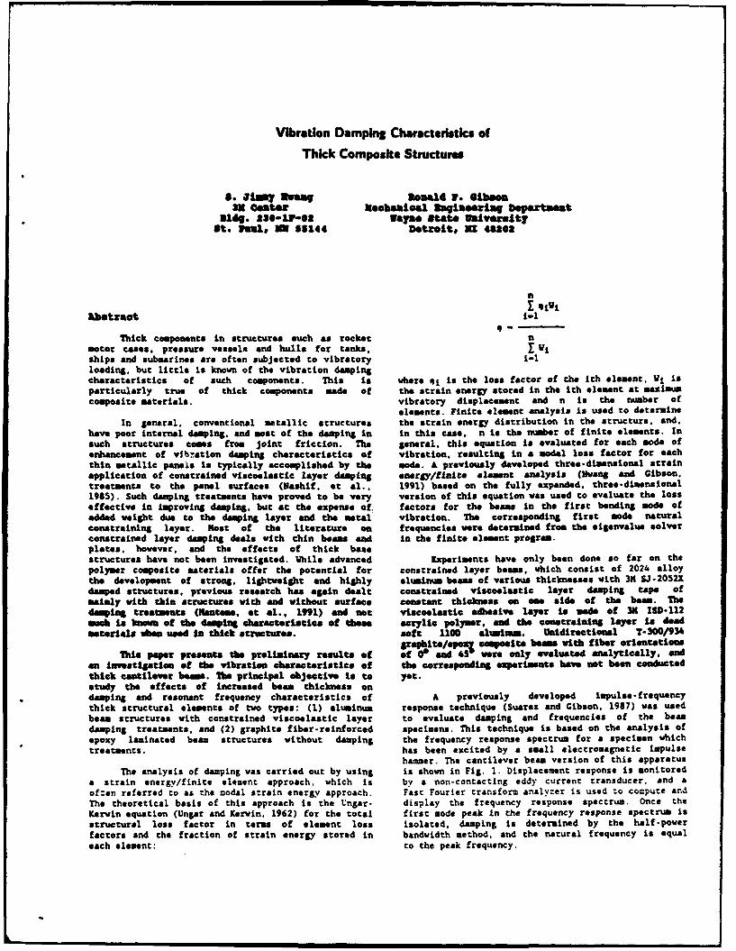
Vibration Damping Characteristics of
Thick Composite Structures
S. 'lmY Rveag nonaa P. GibsonME Comter MeobsLoal Dagneoring epaxtanet
Bldg. 230-I1-02 way" State Walvereltyat. Paule m S5144 Detroit, Rr 48203
n
w~straotI I ivi&btxraet i-I
Thick components in structures such as rocket nmotor cases, pressure vessels and hulls for tanks, Vjships and submarines are often subjected to vibratory i-1loading, but little is known of the vibration dampingcharacteristics of such components. This is where qi is the loss factor of the ith element, Vi isparticularly true of thick components made of the strain energy stored in the ith element at maximmcomposite materials, vibratory displacement and n is the number of
elements. Finite element analysis is used to determineIn general, conventional metallic structures the strain energy distribution in the structure, and.
have poor internal damping. and most of the damping in in this case. n is the nmber of finite elements. Insuch structures comes from joint friction. The general, this equation is evaluated for each mode ofenhancement of vitiation damping characteristics of vibration, resulting in a modal loss factor for eachthin metallic panels is typically accomplished by the mode. A previously developed three-dimensional strainapplication of constrained viscoelastic layer damping energy/finito element analysis (Hl&ng and Gibson.treatments to the panel surfaces (Nashif, et al.. 1991) based on the fully expanded, three-dimensional1985). Such damping treatments have proved to he very version of this equation was used to evaluate the losseffective in Improving damping. but at the expense of, factors for the beams in the first bending mode ofadded weight due to the damping layer and the metal vibration. The corresponding first mode naturalconstraining layer. Most of the literature on frequencies were determined from the sigenvalue solverconstrained layer damping deals with thin beams and in the finite element program.plates, however, and the effects of thick basestructures have not been investigated. While advanced Experiments have only been done so far on thepolymer composite materials offer the potential for constrained layer beams, which consist of 2024 alloythe development of strong, lightweight and highly aluminum beans of various thicknesses with 3H SJ-2052Xdamped structures, previous research has again dealt constrained viscoelastic layer damping tape ofmainly with thin structures with and without surface constant thickness on oae side of the beam. Thedamping treatments (Nmtema, et al., 991) and not viscoelastic adesive layer is made of 31K ISD-112amah is Ium of the damping charactsriatice of thbee acrylic polymer. and the constraining layer is deadmaterials when used in thick structures, soft 1100 alunimm. Unidirectional T-300/934
raphits/oepi composite bes with fiber orientationsThis paper presents the preliminry results of of 0 and 45 were only evaluated analytically, and
On imVestigstien of the vibration characteristics of the corresponding experiments have not been conductedthick cantilever bms. The principal objective is to yet.study the effects of increased beam thickness ondamping and resonant frequency characteristics of A previously developed impulse- frequencythick structural elements of two types: (1) aluminum response technique (Suarez and Gibson. 1987) was usedbeam structures with constrained viscoelastic layer to evaluate damping and frequencies of the beandamping treatments, and (2) graphite fiber-reinforced specimens. This technique is based on the analysis ofepoxy laminated bean structures without damping the frequency response spectrum for a specimen whichtreatments. has been excited by a small electromagnetic impulse
hammer. The cantilever beam version of this apparatusThe analysis of damping was carried out by using is shown in Fig. 1. Displacement response is monitored
a strain energy/finite element approach, which is by a non-contacting eddy current transducer, and aof-en referred to as the modal strain ener&v approach. Fast Fourier transform analyzer is used to compute andThe theoretical basis of this approach is the Ungar- display the frequency response spectrum. Once theKerwin equation (Ungar and Kerwin. 1962) for the total first mode peak in the frequency response spectrum isstructural loss factor in term of element loss isolated, damping is determined by the half-poverfactors and the fraction of strain energy stored in bandwidth method, and the natural frequency is equaleach element: to the peak frequency.
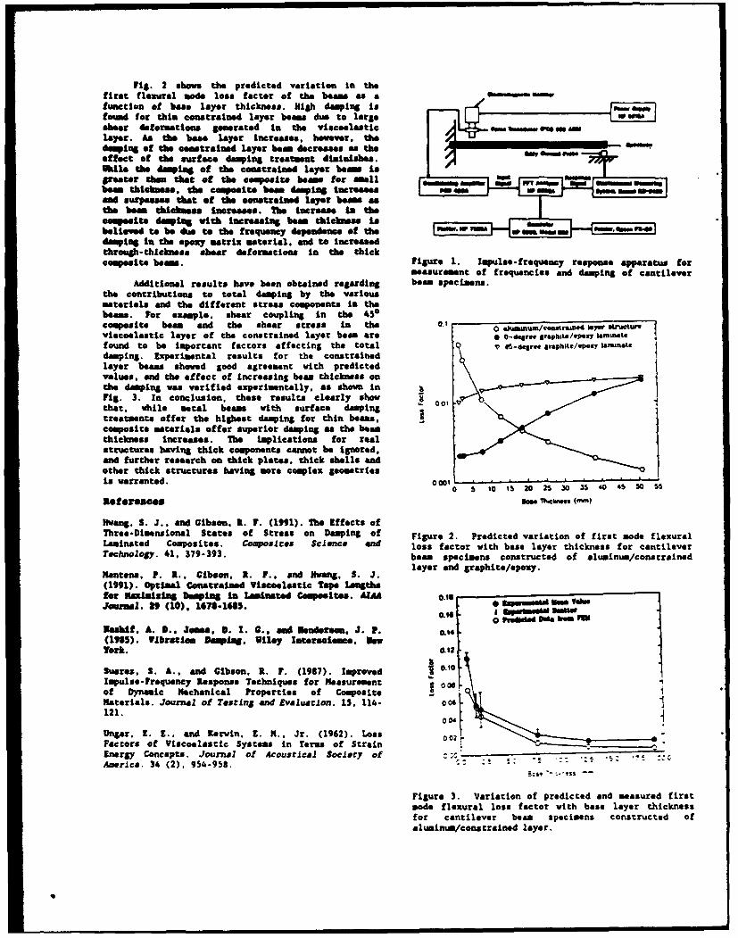
Fig. 2 shows the predicted variation In thef irst flexural mode loss factor of the beams as afunction of base layer thickness. High damping isfounid for thin constrained layer beams due to largeshear deformations generated in the visceelastic0100 "a Va94mlayer. Am the bae" layer increases, however. the_________________damping of the constrained layer boem decrease$ as theeffect of the surface damping treatment dtiminishes. a w"paWile the damift of the constrained layer beam isgreater than that of the composite beom. for saell eoem NGINN60 W NAbeam thichmess, the composite beam damping Increases POP am$aamd surpasses that of the constrained layer beams asthe beam thicknss increases. The Increase io thecemposite domping with increasing beam thicknessa isom.Wvi"INe. o Nbelieved to be due to the frequency dependence of the W "adamping in the epoxy matrix material.* and to increasedthrough-thckness shear deformations In the thickcomposite barns. Figure 1. Impulse- frequency response apparatus for
measurement of frequencies and damping of cantileverAdditionsl results have been obtained regarding bean specimens.
the contributions to total damping by the variousmaterials and the different stress components In thebeams. For example. shear coupling In the 450composite beam and the shear stress in the 0.' 0 atstutviscoelastic layer of the constrained layer boom are 0 0-d~gr.. grophttl/4p17OZ talmoet.found to be important factors affecting the total 45d.rt graphite/epoxy hainufatedamping. Experimental results for the constrainedlayer beams showed good agreement vith predictedvalues. and the effect of Increasing beam thickness onthe damping was verified experimentally, as shown inFig. 3. In conclusion, these results clearly showthat. while metal beams with surface damping 00treatments offer the highest damping for thin beams,composite materials offer superior damping as the beamthickness Increases. The implications for realstructures hawing thick components cannot be Ignored,and further research on thick plates. thick shells endother thick structures having more complex geometriesis warranted. 00010
0 5 10 15 20 n5 30 35 40 45 50 5
Ref erseaes Nose Th~ceras(mm
Hwang, S. J., and Gibson. R. F. (1991). The Effects ofThree-Dimensional States of Stress on Damping of Figure 2. Predicted variation of first mode flexuralLaminated Composites. Composites Science end loss factor with base layer thickness for cantileverTechnology. 41, 379-393. beam specimens constructed of aluminum/constrained
Mantona, P. R., Gibson. A. F., and Hwvang, S. J. layer and graphite/epoxy.(1991). Optimial Coinstrained Viscoelastic Tape Lengthsfor Maximizing bamping In Lainated Composites. At" 0.15__iajozms. t9 (10), 16710-168S. 0 saMsmsew -k- tea.
0.16 - im~aISieNesbif, A. V.. Jones. 3. 1. G.. and Nendersem. J. P. ow0 metima umP(1985). VIbratiom Dampiag. Wiley Interess=i*.e IsswYork. 0.12
0.1Suarez, S. A., and Gibson. R. F. (1967). improved U .1Impulse -Frequency Response Techniques for Measurement -0081of Dynamic Mechanical Properties of CompositeMaterials. Journsl of Testing and Evaluation. 15, 114- 006
Ungar. E. 19., and Kerwin, E. M.. Jr. (1962). Loss 0 02 aFactors of Viscoelastic Systems In Terms of StrainEnergy Concepts. Journal of Acoustical Society of-America. 34 (2). 954-958.
Figure 3. Variation of predicted and measured firstmode flexural loss factor with bass layer thicknessfor cantilever beam specimens constructed ofaluminum/cons trained layer.
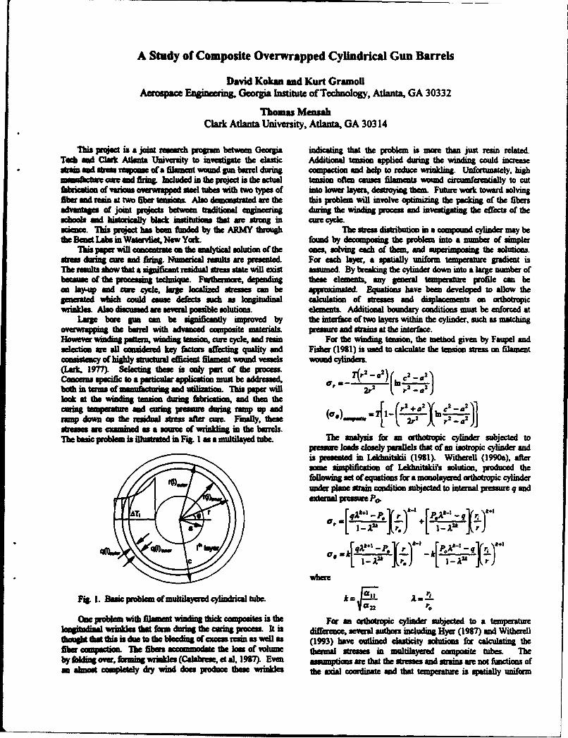
A Study of Composite Overwrapped Cylindrical Gun Barrels
David Kokan and Kurt GramollAerospace EAgi ring, Georgia Institute of Techology, Atlanta, GA 30332
Thomas MensahClark Atlanta University, Atlanta, GA 30314
"whis project is a join research pmgram between Georgia indicating that the problem is more than just resin related.To& and Clank Atlanta University to investigate the elastic Additional tension applied during the winding could inaeasestrai mad smtss response cta filamnt wound pm barrel during compaction and help to reduce wikling. Unfortunately, highiafass cture cae and fring. hIcluded in the project is the actual tension otn causes filamen wound circuminrentially to cutficatiom of various 0 w e teel tubes with two types of into lower layers, destroying them. Future work toward solvingfiber and rein at two fiber temsions Alm denonstrated ae the this prWblem will involve optimiig the packing of the fibenadvantages of joint proects bew traditional w e during the winding proms and investigating the effects of theschools mad histoically bNa* institutions that we troa g in cume cycle.,crme. This prcect has been 6muded by the AMWY through Te sums distribution in a compound cylinder may bethe Bene La b in Waervliet, NewYork found by decomposing the problem into a number of simpler
This paper will concentate on the analytical solution of the ones, solving eua of the, and superimposin the solutions.smn durming re and firing. Numerical results ae presented. For each layer, a spatially uniform temperature gradient isTMh results show that a significant residual sutmn state will mdst assumed. By breaking the cylinder down into a large number ofbeams of the processing technique. Furthermore, depending these elements. my general temperature profile cm bean lay6p and core cycle, ar localized stresses can be appnoximatd. Equations have been developed to allow thegenerad which could cause defects such as longitudinal calculation of stresses and displacements on ortbotropicwrinkles. Also discussed we several possible solutions. elements, Additional boundary conditions must be enforced at
Lag bore gun can be significantly improved by the interface of two layers within the cylinder, such as matchingoverwrapping the barrel with advanced composite materials. presnme and strains at the interface.Howev winduig pattern, winding tension, cure cycle, and rmin For the winding tension, the method given by Faupel andselection me all considered key factors affecting quality and Fisher (1981) is used to calculate the tension stress on filamentconsistency of highly structural efficient filament wound vessels wound cylinders.(a~rk, 1977). Selecting these is only part of the Process. a2 2Concerns: specific to a partcula application mugt be addressed, er- 2r2..2)C2..aboth in tenm of manufcturing and utilition. "This paper willlook at the windn tension during fabrication, and hn thecuin tempeature ad oming pressue during ramp up and u , _[ (!1±+oY. 2 -oa_ramp doam on the residual Wr A ater mne. Finally, thesenm ia 4 ~2 A2 ~.2)rampstresses; me eamined as a source of wrinkhing in the barrels.TheM basic problem is illustrate in Fi*. as a multilayed tube. The analym for an orthotropic cylinder subjected to
prewme loads closely parallels that of an isotropic cylinder andis presented in Likhaitskii (1911). Withlerel (1990a), aftersome simplification of Lekiditskii's solution, produced thefollowing set of equations for a monolayered orthotropic cylinderunder plane strain condition subjected to intanal pressure q andexternal pressure P0.
Or rq;Lk~l P. Jr )4r + q"rF -Prr.,r
qp~ww eft 2e.. -P.Jr( r {P.0ri Jr q
l aI r.
where
Fig. 1. Basic problem of multilayered cylindrical tube.k
one problem with filament widing dthk composites is the For an oribotropic cylinder subjected to a temperaturelongitudinal Wrinkl that form during the urins proces. It is difference, several authors including Hyer (1917) and Witherellt hth st thie s is de to the bleeding of eeesin as well as (1993) have outlined elasticity solutions for calculating thefiber compacion. The fibrs accommodae the loss of vokm therma stresses in multilayred composite tubes. Theby fhli or, foming wril• (C41dwe, et a], 197 Even a ptions me that the stresses and strains me to finctions ofan almost completely dry wind does produce these wrinklM the axial coordinate and tha temperature is spatially uniform
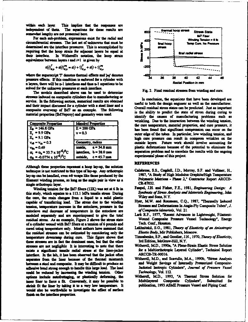
withilk each -aU This implies that the responISs Wreindependent of theta. The equatios for these results are - VWrmai hoop srnsomewhat lengthy amnot presented hue. O- ----- we to
Fair each subiproblan, expresions eais for the radial and U7Fisr
cioMieavntial stresses. The last set of unknowns that must be WhoT*Cu.NPiswdetermined are the interface pressures. This is accomplished by 20 orequirin that the hoop strain for adjacent layers be equal at & Namtheir interface. In Witherell's notation, the hoop strain 0equivalence b atween la yers i and i+1 is given byI
SO)' + CO"- eO + 1,+ SO + )IL -----
whom the superscript T denotes thermal effects and )sq denotespressureffects. yhs canditios is enfcrced for acylinder with 36 36 40 42 44 46n layers therm will be n-I interfaces and thus n-I equations to be RodIki Position )in It
solved for the unmkown pressures at each interface. i.2 ia eiulsress ie idn n eThe models described above can be used to detammie Fg .Fnlrsda tessfo idn n ue
stresses induced an composite cylinders due to manufacturing or In conclusion, the equations that have bees devieloped areservice. In the following section, nmaerical resuts we obtained usfu to biotuh tue design esginee as well as the manufacturer.and thei impact discussed for a cylinder with a steel liner and a Oveall residual sumes states con be predicted. Just as importantcomposite overwrap of IM7 as an example. Tim following5 is the ability to predict the state of stres during cuings tomaterial propifties (M7/epoxy) and geomety were used. identify, the causes of manufacturing problems such as
CompositetoetcMadl Properties wrnln.Det h itrcion betwees the winding tension,F4 -146 ItG~aE -200 ft he um emprshre, ateialproertesand cue pressure, it
Es -146. ON -20 ONhas been found that significant compression can occur on theE, i9.9 GFa v - 0.3 outer edg of the tubes. In particular, low winding tension, andE, 9.1 ON _ __ _ __ high cwe pressure con result in compress wrinkles on theVie =, -I=0.3 Geometry, radius outside layers. Future work should involve accounting forV0 - 0.49 inside, a -34. amn plastic deformations becaus of the potential to eliminate the
%- aL, - 33.7 x 1Io4 pC intarface, b - 33.0 zm sem ato problem and to correlate the results with theonigas - .0.0774 x 10o4 PC outside, c -n45.7i emperimental phase of this projecL
Although these properties represent a hoop lay-up. the solutiontechnique is not restricted to this type of lay-up. Any ortholropic Calabrese, S.S., Cogdell, I.D., Murray, S.F. and Vollmae, I-L,"lyu can be handled, eves *0 wraps like those produced by the 1997, -A Study of High Modulus Grapkituifigh TemperatureMolment winding process, so long as the angle pair is view as a Polymeric Matrices - Phane 2.' Contractor Report ARCCB-single Getotropic lyer. CR47032.
Winding tension for the IMW fibers (12X) was set at 6lb in Faupel, 31.I and Fisher, FYE., 1911, Engiuweing Design: Athis study, whic equates to a 113.1 MP&a tensile stes During Sjsiduias of Seres AnalYas and Material, Engirsx r, Johnthe cure, the resn changes firon a liquid to a soli plastic Wiley and sons, N.Y.capable of ft askning lod 71 - u oth idn Hyer, M.W. and Rousseau, C.Q., 1927, Mushmally Inducedtension, temperature incease in the autoclave, pressur in th Stresses; and Defonnations; In Angle-Ply Composite Tubes', JIautoclave and decrease of temperature in the autoclave we qfCou~spoarA*MamigL,, Vol.- 21.modeled separately and am superimposed to give th oa Lark R.F., 1977. 'Recent Advances in Lightweight, Filament-residual stress As an example, Figure 2 shows the -trmom state Wound Composite Pressure Vessel Technology', Energyof cylinder wound with 11.7 fibers at a tension of 6 pounds and Tech. Conf., Hiouston.cured using temperature only. Most authors have assumed that 1-khnitaWi, S.O., 1911, Theoey qfEksddtcy of an Axircnpithe residual stresses cmn be estimae by considering only the ElasticBody, Mir Publishers Moscow.tampereture dowranp during ce. This figure shows that Timoshesko, S.P., and Goodier, JM., 1970, Theoey of Elmadlciy,these sorassesa in fact the dominant ones, but that the other 3rd Edition, McGraw:Hil, N.Y.stesses am not negligible It is interesting to note that there Writherell, M.D., 1990a, "A Plane-Strain Elastic Stres Solution
acists a significant tensile radial stres at the liner-jacket for a Multiorthotropic: Layered Cylinder*, Technical ReportWserfsate Is the lab, it has bees observed that the jaket often ARCCB-TR-90016.separates from the Imer beca~use of the thermal mimatch Witherell, M.D., and Scavullo, MA., 1990b, 'Stress Analysisbetween a stee and composite. It may be difficult to produce an and Weight Savings of Internally Pressurized Composite-adhesive bond sftron enough to handle this large load. The load Jackeated Isotropic Cylinders', Journal of Pressure Vesselcould be reduced by increasing the winding tension Other Teclnolog# Vol. 112.option include autoftettaging or plastically deforming, the Witherell, M.D., 1993, 'A Thermal Stress Solution for
inrliner to force a fit. Conversely, it may be possible to Multilayered Composite Cylinders', Submitted forduink fit the liner by taking it to a very low temperature. It publication, 1993 ASME Pressure Vessel and Piping Costwould also be worthrwhile to investigate Use effect of surfacesmii on the inuterfae propertieL
DELAMINATION DYNAMICS AND ACTIVE CONTROL OF DELAMINATIONS
S. HanagudSchool of Aerospace EngineeringGeorgia Institute of Technology
Atlanta, GA 30332-0150
To date, most of the efforts that are directed towards controlling the delamination are passiveand are focussed on preventing the formation of delaminations. Several passive options that havebeen proposed include an optimization of the lamina sequence, an introduction of special adhesivelayers, and to serrate the fiber - matrix interface. Even when all these passive options areimplemented, delaminations do develop in practice. Active control of delaminations is an alternativein such cases. In the rotorcraft technology, some of the applications include delamination control inthe flex beam of bearing less rotor system, a composite hub and critical areas of the airframe. Theobjective of our studies are to explore the feasibility of real time detection of delaminations in alaminated composite structure and use this information to develop active controllers to prevent thesedelaminations from further growth. Steps that are necessary in achieving this objective are as follows:Techniques are needed to sense and detect the existence, size and location of delaminations. We alsoneed dynamic models for the delaminated system that can be used as the plant model to designcontrollers. Other items of investigation are structural mechanics foundation for controller designand actuator options.
In this paper, we will discuss our work in the area of delamination detection techniques byusing the change of dynamic characteristics due to delaminations. These techniques offer thepotential of being used in real time detection techniques. We have developed an analytical dynamicmodel for delaminated beams. Theoretical solutions of the beam equations that natural frequenciesof delaminated beam are different from the frequencies of a non-delaminated beam. The solutionsalso indicate the existence of an additional frequency and a corresponding mode due to the presenceof a delamination. This can be called as an opening mode of the delamination or a delaminationmodes. We have validated some of our theoretical studies by means of experimental modal analysis.The presentation will include the preliminary work in the area of active controL
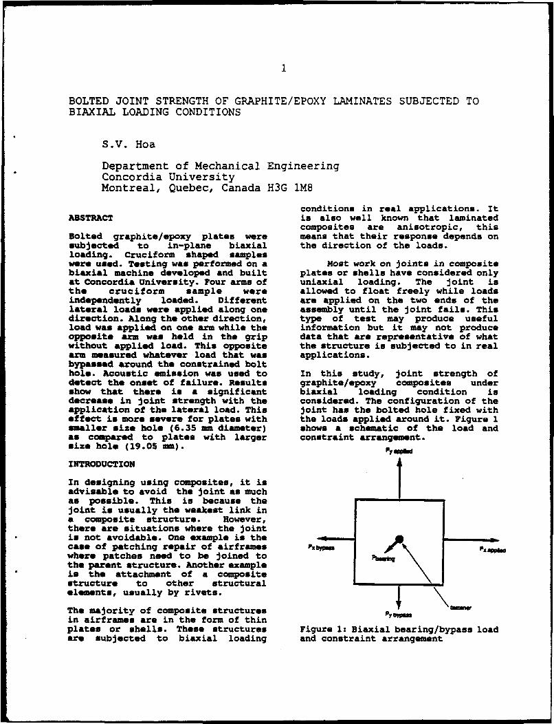
BOLTED JOINT STRENGTH OF GRAPHITE/EPOXY LAMINATES SUBJECTED TOBIAXIAL LOADING CONDITIONS
S.V. Hoa
Department of Mechanical EngineeringConcordia UniversityMontreal, Quebec, Canada H3G 1M8
conditions in real applications. ItABSTRACT is also well known that laminated
composites are anisotropic, thisBolted graphite/epoxy plates were means that their response depends onsubjected to in-plane biaxial the direction of the loads.loading. Cruciform shaped sampleswere used. Testing was performed on a Most work on joints in compositebiaxial machine developed and built plates or shells have considered onlyat Concordia University. Four arms of uniaxial loading. The joint isthe cruciform sample were allowed to float freely while loadsindependently loaded. Different are applied on the two ends of thelateral loads were applied along one assembly until the joint fails. Thisdirection. Along the other direction, type of test may produce usefulload was applied on one arm while the information but it may not produceopposite arm was held in the grip data that are representative of whatwithout applied load. This opposite the structure is subjected to in realarm measured whatever load that was applications.bypassed around the constrained bolthole. Acoustic emission was used to In this study, joint strength ofdetect the onset of failure. Results graphite/epoxy composites undershow that there is a significant biaxial loading condition isdecrease in joint strength with the considered. The configuration of theapplication of the lateral load. This joint has the bolted hole fixed witheffect is more severe for plates with the loads applied around it. Figure 1smaller size hole (6.35 -m diameter) shows a schematic of the load andas compared to plates with larger constraint arrangement.size hole (19.05 mm). q
INTRODUCTION
In designing using composites, it isadvisable to avoid the joint as muchas possible. This is because thejoint is usually the weakest link ina composite structure. However,there are situations where the jointis not avoidable. One example is thecase of patching repair of airframes Pxby mwhere patches need to be joined tothe parent structure. Another exampleis the attachment of a compositestructure to other structuralelements, usually by rivets.
The majority of composite structuresin airframes are in the form of thinplates or shells. These structures Figure 1: Biaxial bearing/bypass loadare subjected to biaxial loading and constraint arrangement
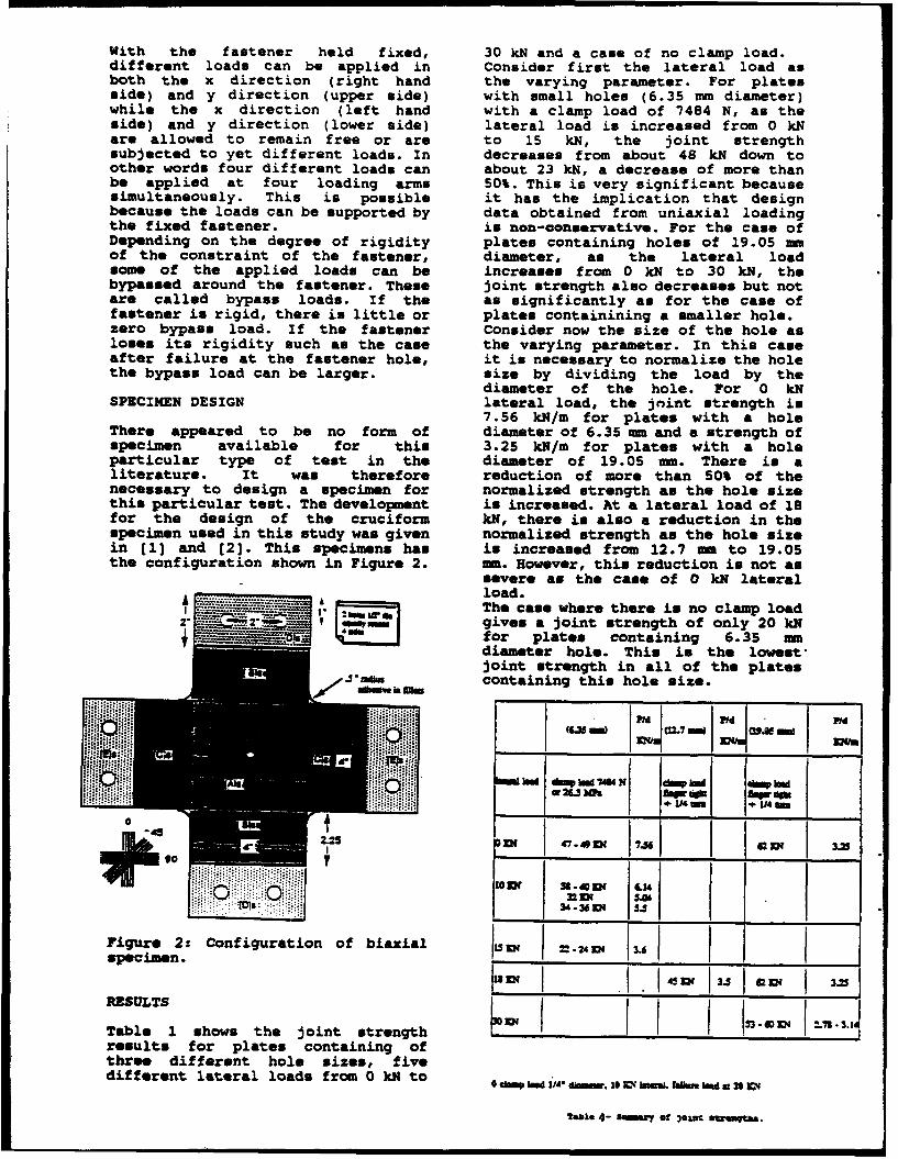
With the fastener held fixed, 30 kN and a case of no clamp load.different loads can be applied in Consider first the lateral load asboth the x direction (right hand the varying parameter. For platesside) and y direction (upper side) with small holes (6.35 mm diameter)while the x direction (left hand with a clamp load of 7484 N, as theside) and y direction (lower side) lateral load is increased from 0 kNare allowed to remain free or are to 15 kN, the joint strengthsubjected to yet different loads. In decreases from about 48 kN down toother words four different loads can about 23 kN, a decrease of more thanbe applied at four loading arms 50%. This is very significant becausesimultaneously. This is possible it has the implication that designbecause the loads can be supported by data obtained from uniaxial loadingthe fixed fastener. is non-conservative. For the case ofDepending on the degree of rigidity plates containing holes of 19.05 mmof the constraint of the fastener, diameter, as the lateral loadsome of the applied loads can be increases from 0 kN to 30 kN, thebypassed around the fastener. These joint strength also decreases but notare called bypass loads. If the as significantly as for the came offastener is rigid, there is little or plates containining a smaller hole.zero bypass load. If the fastener Consider now the size of the hole asloses its rigidity such as the case the varying parameter. In this caseafter failure at the fastener hole, it is necessary to normalize the holethe bypass load can be larger. size by dividing the load by the
diameter of the hole. For 0 kNSPECIMEN DESIGN lateral load, the joint strength is
7.56 kN/m for plates with a holeThere appeared to be no form of diameter of 6.35 mm and a strength ofspecimen available for this 3.25 kN/m for plates with a holeparticular type of test in the diameter of 19.05 mm. There is aliterature. It was therefore reduction of more than 50% of thenecessary to design a specimen for normalized strength as the hole sizethis particular test. The development is increased. At a lateral load of 18for the design of the cruciform kN, there is also a reduction in thespecimen used in this study was given normalized strength as the hole sizein [11 and (2]. This specimens has is increased from 12.7 mm to 19.05the configuration shown in Figure 2. mm. However, this reduction is not as
severe as the case of 0 kN lateralload.NO Ur as The case where there is no clamp load
"" • m gives a joint strength of only 20 kNI • for plates containing 6.35 mmY ~diameter hole. This is the lowest,
joint strength in all of the platesj . - containing this hole size.
rpec*__n. - -z
NX02.W 7 )W (OM
resltsfo plte cotanin odifeen badra load load 740 do* ko
OCR 47-449E 17 i *-6 -N 31OZ 3U~~l C14
T8X 40M f3~ta:•
2 3 i i 54
Figure 2: Configuration of biaxial 13 JK =-4Z 3.6 ---
specimen. I___
R.ESULTS L IW 133 - - O - K - ITable 1 shows the joint strength .i..-results for plates containing ofthree different hole sizes, fivedifferent lateral loads from 0 kM to MIn ** kmr104WMLab edt20L
table 4- sommrx of 3exat s~taoqa.
HIGH-STRAIN-RATE BEHAVIOR OF GR/EP LAMINATE UNDER TRANSVERSE IMPACT
Piyush K. DuttaU.S.Army Cold Regions Research and Engineering Laboratory
Hanover, NH 03755
and
David HuiUniversity of New Orleans, New Orleans, LA 70148
Extended Abstract
Much of the early work on the the striker's length. The testdynamic mechanical response of fiber- specimen is held between the two barsreinforced composites used impact bend in a chamber cooled by liquidtests of Izod or Charpy type [1,2]. nitrogen. At the interface, someThe complex loading system in such energy of the stress pulse from thetests does not allow a fundamental first bar is reflected because of theinterpretation of the data obtained mechanical impedance mismatch of theand prevents any simple analysis of bar and the specimen. The rest isthe effect of loading rate on the transmitted into the specimen,failure processes. For this reason propagates through It, and reaches theover recent years attempts have been second bar's interface with themade at the U.S. Army Cold Regions specimen. At the second interface,Research and Engineering Laboratory, part of the stress pulse is againHanover, New Hampshire, to develop reflected back into the specimen andimpact tests for fiber-reinforced the remainder is transmitted to thecomposite materials in which a simpler transmitter bar. If the specimen isloading system is applied and account much shorter than the wavelength ofcan be taken of stress wave effects. the loading pulse, the wave-Version of the the split Hopkinson's transmitting time will be smallpressure bar apparatus for-simple compared with the duration of theuniaxial compression has been designed loading stress pulse, and after a fewand large strain rate effects are reflections within the specimen, thebeing investigated on 48-ply GERP, stress and strain along the specimenwhere mechanical response is strongly become approximately uniform.rate dependent. Consideration of equilibrium at
The CRREL Hopkinson Bar Impact the interface between the specimen andApparatus consists of a short striking the transmitter bar shows that thebar driven by compressed air and two forces in the specimen and in thelong, solid, round bars instrumented transmitter bar are equal. The forcewith strain gauges. The striker's is determined by measuring the strainimpact on the first bar sets up a on the elastic transmitter bar usingcompressive stress pulse, whose strain gauges and the average strainamplitude depends on the impact in the specimen is calculated from thevelocity and whose duration depends on displacements at the end of the
specimen using equations (1), (2), and(3).
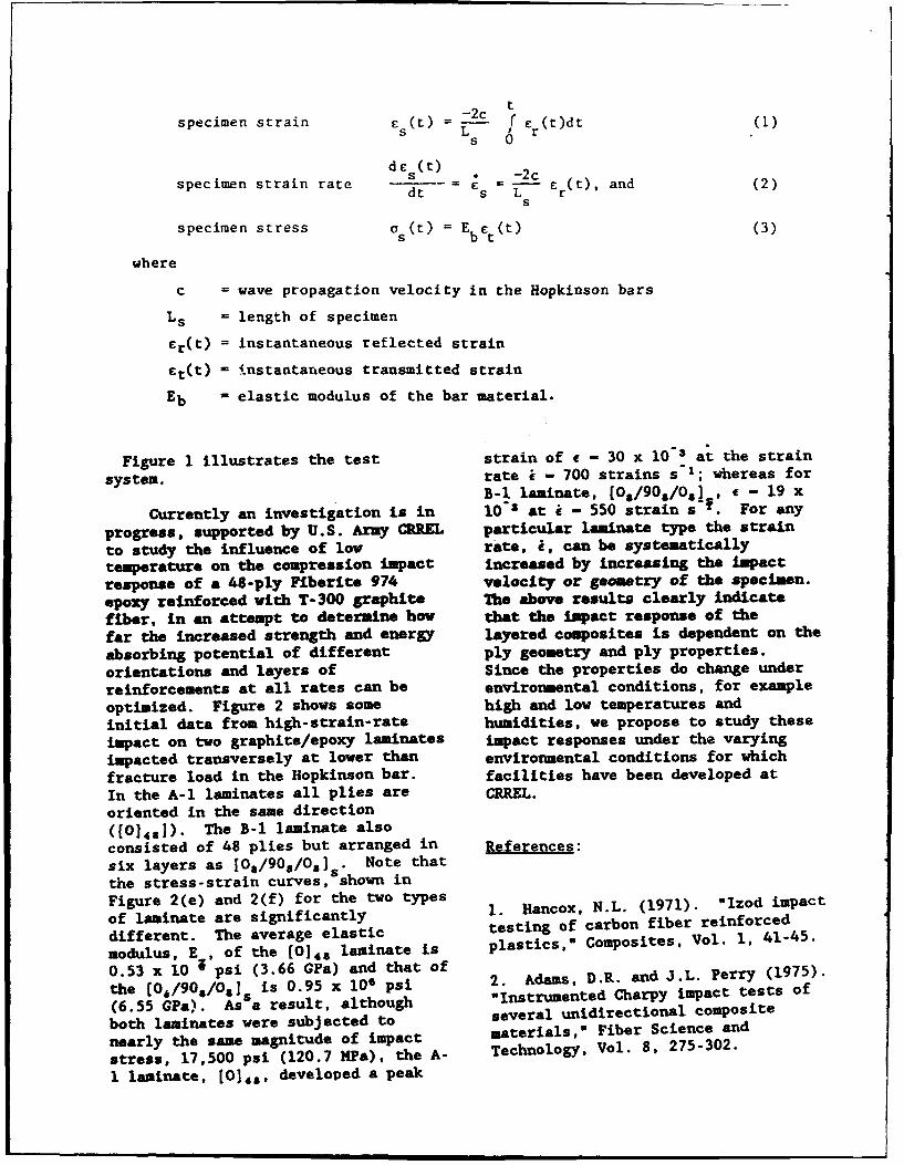
-2cspecimen strain E (t) - i Cr (t)dt(
s 0dE (t)s -M =-2c
specimen strain rate dt s L---- (t), and (2)s
specimen stress a s(t) E Eb ct(t) (3)
where
c = wave propagation velocity in the Hopkinson bars
Ls = length of specimen
Er(t) = instantaneous reflected strain
Et(t) - instantaneous transmitted strain
Eb = elastic modulus of the bar material.
Figure 1 illustrates the test strain of e - 30 x l0" at the strain
system. rate i - 700 strains s-1; whereas forB-i laminate, [0s/90s/O1, e - 19 x
Currently an investigation is in l10" at i - 550 strain s T. For any
progress, supported by U.S. Army CREEL particular laminate type the strain
to study the influence of low rate, i, can be systematically
temperature on the compression impact increased by increasing the impactresponse of a 48-ply Fiberite 974 velocity or geometry of the specimen.epoxy reinforced with T-300 graphite The above results clearly indicatefiber, in an attempt to determine how that the impact response of the
far the increased strength and energy layered composites is dependent on the
absorbing potential of different ply geometry and ply properties.orientations and layers of Since the properties do change underreinforcements at all rates can be environmental conditions, for example
optimized. Figure 2 shows some high and low temperatures and
initial data from high-strain-rate humidities, we propose to study these
impact on two graphite/epoxy laminates impact responses under the varying
impacted transversely at lower than environmental conditions for which
fracture load in the Hopkinson bar. facilities have been developed at
In the A-1 laminates all plies are CRREL.
oriented in the same direction([0]4s]). The B-1 laminate alsoconsisted of 48 plies but arranged in References:six layers as [Os/90s/Os] . Note thatthe stress-strain curves, shown inFigure 2(e) and 2(f) for the two types 1 N.L. (1971). "Izod impactof laminate are significantly t.stingof c.L. fiber rinoddifferent. The average elastic testing of carbon fiber reinforcedmodulus, E , of the (0]4s laminate is plastics" Composites, Vol. 1, 41-45.
0.53 x 10 psi (3.66 GPa) and that ofthe [fO/90s/0s]s is 0.95 x 10' psi 2. Adams, D.R. and J.L. Perry (1975).
(6.55 CPa). As a result, although -Instrumented Charpy impact tests of
both laminates were subjected to several unidirectional composite
nearly the same magnitude of impact materials," Fiber Science and
stress, 17,500 psi (120.7 MPa), the A- Technology, Vol. 8, 275-302.
1 laminate, [0]48, developed a peak
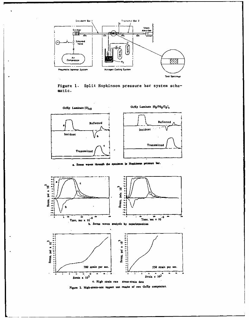
Incident So, 'nri
o h~
Solenod
AirCompnessom
Pnrsrmotic lNoMme sy~stem' Nitrogmn Coming System
Test Specrimen
Figure 1. Split Hlopkinson pressure bar system sche-mati c.
GOrEP Laminate 10143 Ot/Ep Laminate IO108I9OIsgJ
RenectedRan fited
Transmitted j'
A. Sames waves 111=6g die apecimen in Hopkinsul pCs"WO b.-
CC
0.'11
Time. sec a 10 "rune. sec x 10It. Stress waves analysis by superimposition
00 P,
Strain~ ~ ~ ~ a 03Sran1
c. iabstrinrat stes-sri data
Figure~~ ~ ~~ 2.'g-tanrt matts rslso w rE opsts
Impact of Fiber Composite Laminate Plates: A Percolation View of Perforation and Spallation
Zeev Jaeger', Misha Anholt1 , and Arnold H. Mayer2
1 SW"q Nuceii RtarMh Con". Yawl, Wt"ni
2 WrgW9 ULtamy, WPAFS. ON
Abstract
In a series of Impact experiments on composite to the well known result (4) that the average fragment
plates which were aimed at testing the conjecture size becomes smaller the higher the strain rate.
that the perforation threshold represented a critical Moreover, they provide the physical justification forphenomenon and that Percolation Theory could using percolation theory in predicting fragment sizeeventually provide an adequate description of the distributions. (2.3)spalbtlon or fragmentation process accompanying Percolation theory (1) has been recognized as a
the perforation of anisotropic layered materials, the statistical physics model for critical phenomena. By
fragments emerging from a 0190 layup fiber epoxy applying it to fracture and fragmentation problems weplate target were collected and photographed. Image were able to show that fragmernation (as well as the
analysis techniques were used to deduce the size coalescence of many microcracks forming adistribution of the backside fragments. It was found macroscopic fracture) is a critical phenomenon.that the number N of fragments having area S may Fragmentation occurs whenever the density of cracks
be represented as a power law N -1 I /S J The reaches its critical value. That Is to say, that when
average exponent for the experiments which were the probability, p, of creating a microcrack achieves
performed at nine different values of Impact velocity the critical value, p.. For crack densities higher than
over the range from 300 to 6000 fps had the value J PN, the critical density of microcracks, the number of
a 2.17 ± 18 %, which lies between the previously small particles in the population grow at the expensepredicted theoretical values from Percolation Theory of the reduction of th'. number of large ones.of J(2D) a 2.05 and J(30) 2.2. For the velocity V, Consequently, the lotal surface area of the fragmen',s
* 397 fps which is close to the perforation threshold is growinG. it is therfore, expected, that the minimalvelocity, J had the value 2.03 , which is surprisingly surface energy required for fragmentation is receivedclose to the two dimensional Critical Percolation at pe ( below p. a complete shattering of the finiteLimit. macroscopic piece of material is not possible).
Coming back to impaci physics, the determination ofIntroduction the limit velocity below which perforation of a given
target by a given projectile is not possible continuesThe mechanical properutes of a composite are to be of much interest. Even the definition of theseverely degraded by impact induced damage. A ballistic limit (5) (the critical value of striking velocitysignificant fraction of the projectile kinetic energy is at which the probability of perforation is 50%)channelled Into rival modes of damage., I.e. suggests that stochastic mechansms are at play.delamination, fiber fracture, matrix cracking and Below the ballistic limit, it Is expected that the spalledfragmentation. Some disintegration appears around fragmented zone at the backside of the sample andand Inside the penetration hole, and at the backside the shattered and penetrated zone in the front sideof the target spell is produced even at velocities less will be well separated by a zone of delaminatedthan the ballistic limit. More energy Is consumed material strong enough to prevent the projectile fromabove this limit, as intense fragmentation emerges perforating the target. In the limit as this intact zonefrom the target. This process may be studied becomes very thin, these two zones will touch eachquantitatively by measuring the fragment size other, and the sample will then become disintegrateddistribution, throughout its thickness. It Is of Interest to inquireUnder a short impulse of pressure, a situation typical whether the critical condition for fragmentationof either an Impact or an explosion is created. The supplied by percolation theory is able to yieldstress acts in a local way and is "unable* to scan the additional information about the ballistic limit and themedium for its weakest points. Therefore, many physical conditions of its occurrence.cracks grow simultaneously and independently indifferent regions of the target. These conditions lead Description of the Experiment
• " •i
Image Analysis percolation in the plane, D = 1.9 (20). In three
dimensional space D = 2.5 (3D). An additional result
The population of fragments from each experiment of percolation theory (1) is that the number n. of
was collected on the inner surface of a cylindrical clusters having s sites (per site) is given by n% - 1 / Ssheet of paper coated with a sticky adhesive. After J where J = (d+D) / D. and where the exponent Jthe experiment, the cylinder was rolled fiat and has the value J = 2.05 in two dimensions and Ju 2.2photographed. Such a procedure has to be carried in three dimensions (d=3). All the slopes in Table Iout with caution In order to avoid any optical noise are around these values with an error not exceedingresulting from shadows, unequal illumination or about 20%. Furthermore, in the introduction, aspurious p.kiais. possible relation between the perforation thresholdThe photographs were scanned and a digitized Image and critical fragmentation was conjectured. Thewas obtained. The next step Is the division of the lowest velocity in Table I Is not far from thedigital Image Into clusters of material (fragments) and perforation threshold found experimentally (6), namelythe background. This procedure is not easy when V a 375 fps. The slope of the correspondingthe gray levels of the fragments and local V f 375 dis. is s xoee l o theobackground overlap. Also, it Is not easy to fragment size distoibution is extremely dcose to thedistinguish two fragments partially overlapping each theoretical value of J for the two dimensional case. Ifother. Sperlal data treatments were adopted to the fragments of the impacted composite plate havereduce distortion and deterioration of the information a fixed thickness (as would be the case If it theyrecorded in the digital picture, which was scanned by resulted from the fragmentation ofa 512 X 512 black and white scanner. Higher deiaminated plies), then the measured arearesolution of the original photograph, of course, will distributions would represent, in fact, two dimensionalresult In higher final resolution and consequently mass distrbtions. In a laminated material withmore data on possible lost Infonmutton with regard to planar weaknesses between the plies, such amore dae at.n prsiments, hypothesis appears plausible. In general IsotropicThe measured fragment size histograms vay solids, a true three dimensional bebhaviour iscontinuously in an irmegulr way. In orer to expected with J = 2.2. It Is interesting to checkovennuo the effects of random fluctuatIons, o t whether fragment size distributions from Impactedesults were accumulatod in bins having unequal brittle soldis also behave In the same way near the
"width. Each bin fher along on tize x -a perforation limit. More work Is needed In order tomade twice as bilge as the preceding one. The total correlate other statistical Physics features either with
number N of occurences In a bin was divided by dynamical predictions or with experimental data.bin width, to obtain the average distribution density ofsize S. A inear least squares fit of log N against log ReferencesS was performed in order to deduce the parameters (1) 0. E. Grady, J. Appl. Phys. 53,322(1982)of the expected power law relationship.The results (2) R. E.Grad, N. Appl. Phys. Jaeger (1 l.2)am presented in Figure 1. The slopes and tercepts (2) R. Engman, N. Rer and Z. Jaeger Phil. Magof the linear fits are presented In Table 1 for each 856, 751 (1988)veloity.(3) M. Anholt, R. Englman and Z. Jaeger,veoloc f. s "Percolation Approach to Locally Caused
e be oFragmentationw, Centre de Physique, Les-Houches,,#as recognized by Grady (3) In the early eighties. France, D. Beysems et. al. Eds, April 12-17 1993The highest strai-rathe fo during an impact may (4) 0. Stauffer "Introduction to Percolation Theory",be estimated by the ratio of the projectile to i Taylor and Francis, London 1985radius, de/dt -Vp I Ip. Strain rates at the backface (5) J. A. Zukas, "Penetration and Perforation ofmay be estimated by multiplying this value by some Solids", chap.5 In "Impact Dynamics", J. A. Zukas, T.attenuation function for the particle velocity. In any Nicholas, L. B. Gresczuk and D.R. Curran Eds, Wileycase, it is expected that the higher the impact energy N.Y. (1982)is, the smaller will be the average fragment size. It is (6) G. J. Czamecld, "A Preliminary Investigation ofnot surprising therefore that the trend of intercepts in Dual Mode Fracture Sustained by Graphite/EpoxyTable I really represents the fraction of fine particles Laminates Impacted by High Velocity Sphericalin the distribution. The behavior of the slopes needs Metallic Projectiles" MS Thesis, University offurther consideration. The mass of a fractal structure Dayton, OH (1992)having a length L (>>1) is given by M(L) - A L D
where D is the fractal dimension. At the critical point,p ape, the value of D Is known. For homogeneous
Impact Dynamics and Damage initiation in Laminated composites
S. P. Joshi, University of Texas at Arlington; Klaus Friedrich and Jozsef Karger-Kocsis, University ofKaiserslautern; Alexander Bogdanovich, Latvian Academy of Sciences
Low velocity impact induced damage as- The temporal characteristics of the impactsessment requires knowledge of contact behavior, loading are also important. The difference in ratestransient elastic wave propagation, crack nucle- at which the incident energy is imparted to theation, and propagation and interaction. The initial structure and propagated away from the impactcrack formation takes place in and near the contact point is responsible for the high stress build-up inregion and therefore is sensitive to the indentation the near-contact region. The contact area and thebehavior. A detailed dynamic stress field based on traction distribution changes with change in re-the realistic contact laws (1] provides information sultant contact load with time. In a dynamic con-about highly stressed zones in the undamaged tar- tact, spatial and temporal characteristics of theget composite structure. These zones can be iden- contact are coupled. The use of static indentationtified as crack initiation domains. The stress field laws may be considered and is justified under thein these crack initiation domains is used to identify following assumptions:the stress components responsible for cracks nu-cleation. Once the crack nucleation is recognized, 1. The total contact duration is a order of magni-propagation can be studied with the help of the tude longer than the time taken by the longitudinalfracture mechanics principles. However, it should waves to travel through the thickness of the targetbe recognized that the dynamic stress field at every composite, assuming thickness is the smallest di-stage of propagation is very complex and therefore mension.intractable to detailed study. It is clear that theelastic stress field, although complex, is well de- 2. The rate of change of contact area is a order offined up to the point of initial fracture. Joshi and magnitude smaller than the characteristic inplaneSun (2,3] presented a simple study incorporating longitudinal wave velocity.the above mentioned notions of the impact-in-duced damage initiation in laminated composites. 3. The impactor dimensions are comparable to the
thickness dimension of the target or it is very stiffThe impact damage in laminated compos- compared to the target. This rules out effect of
ites has been an active research area for a long elastic wave propagation in the target.time which is evident from the vast amount of lit-erature available in this area. The purpose of this The numerical results in this study are ob-paper is to discuss some important features of con- tained by incorporating static indentation laws intact behavior, transient incident energy propaga- conjunction with the plate and impactor dynamics.tion and crack nucleation with the help of The temporal distribution of contact force is ob-numerical and experimental results. tained by employing a plate finite element analysis
[5] with the static experimentally obtained inden-Determination of spatial and temporal dis- tation laws (6]. The effect of spatial variation of
tribution of contact traction is important in impact the impact load on through-the-thickness distribu-studies. It is apparent that the traction distribution tion of stresses is captured by considering a planeover the contact area can have a profound influ- strain problem of an infinitely wide plate impactedence on the nature of the near contact stress field. by a rigid cylindrical impactor. The contact lengthFor example, compare the Boussinesq stress filed during the impact is calculated by modified Hert-[4] in a half space subjected to point load to a Hu- zian indentation law, providing elliptical force dis-ber stress field [5] with distributed load according tribution over the contact length. The previouslyto Hertz analysis. The spatial distribution of the obtained (from the plate analysis) temporal distri-impact load should not be ignored when studying bution is implemented as resultant impact load inimpact-induced fracture initiation occurring in the the cylindrical impactor problem. The quantitativenear-contact region. information about the loading is lost in doing so,
I Joshi, Friedrich, Karger-Kocsis, Bogdanovich
while the qualitative nature of the impact loading ture) restricts transverse normal stress from be-is retained. The contact length, obtained using the coming significantly tensile.Hertzian law, is scaled to match the experimental-ly obtained contact. The spatial distribution of the Crack nucleate in region of high stressload is assumed to be elliptical and is applied as concentration. These stress produced cracks orientconsistent nodal forces within the contact length. themselves perpendicular to the maximum tensileThe nodal forces are modified at every time step principal stress direction in the brittle isotropicintegration, depending on the contact length and material by a smooth impactor is experimentallyresultant impact load. verified [7]. In case of anisotropic solids, it is nec-
essary to take into account the orientation depen-Elastic waves travel at different phase dence of both elastic constants and surface energy.
speeds in different directions because of anisotro- Clearly, in composites with strong directionalpic material properties of the target. The initial cleavage tendencies, the anisotropy in surface en-stress field in the vicinity of impact is solely due to ergy will govern. In general, though, we expectincident energy if the geometric boundaries are some compromise between the tendencies forsufficiently away from the impact point. The rela- cracks to be orthogonal to maximum tensile stresstive importance of reflected energy (geometric and weaker cleavage planes. Each ply of the lami-boundary conditions) in initiating damage may be nated composite plate may be considered as trans-resolved by comparing the time taken by the dom- versely isotropic, with plane of isotropy beinginating frequency component of the initial pulse to orthogonal to fiber orientation of the ply. There-reach the impact region after reflection within the fore, the crack will nucleate orthogonal to the ma-impact duration itself. It should be noted that in- jor component of tension in the isotropic plane ofterference between initial pulse and the reflected the ply. Initial impact damage can be explainedpulse can be constructive or destructive. We will with the help of this hypothesis.restrict the discussion to non-interference cases.
Representative numerical and experimen-We expect three dimensional stress field in tal results will be included in the full length paper
the vicinity of the impact center (a region with di- to substantiate the arguments and elaborate on themensions of the order of maximum contact length) various aspects of the low velocity impact present-and two dimensional (plate or shell type) stress ed above.field in the far-region. The thickness dimensionplays an important role. The Near-Impact-Stress- This research is partially funded by NATOField (NISF) is considerably different in thick and grant No. CRG 920 125.thin laminated composites. The NISF is also al-tered by the boundary conditions on distal surface REFERENCES(free surface or surface resting on rigid supportetc.) which is the nearest surface from impact 1. Tan, T.M. and Sun, C.T., NASA CR- 168057, Decem-point. The transverse normal stress in NISF has to ber 1982.satisfy compressive normal traction on the contact 2. Joshi, S.P. and Sun. C.T.. J. of Composite Materials,surface and zero traction on the rest of the proxi- Vol. 19, No. 1, 1985, 51-66.mal surface and the distal surface; this surface is 3. Joshi, S.P. and Sun, C.T., J. of Composites Technolo-free in most of the practical problems. In general, gy and Research, Vol. 9, No. 2, 1987, 40-46.the impact duration is far greater than the time tak- 4. Lawn, B.R. and Swain, M.V., J. of Material Science,en by a longitudinal wave to travel through the Vol. 10, 1975, 113-122.thickness and, therefore, the through the thickness 5. Lawn, B.R., J. of Applied Physics, Vol. 39, 1968,4828-4834.distribution of the transverse normal stress will not 42-84dsalteron of the tranversetnofromal tress will nota. 6. Chen, J.K., Ph.D. Dissertation, Purdue University,be altered by the reflection from the distal surface. 1984.This means that the problem is quasi-static in the 7. Yang, S.H. and Sun, C.T, NASA CR-165460, Julythickness direction which also justifies use of stat- 1981ic indentation laws. These two attributes of the & Mikosza, A.G. and Lawn, B.R., J. of Applied Physics,NISF (boundary conditions and quasi-static na- Vol. 42, 1971, 5540-5545
2 Joshi, Friedrich, Karger-Kocsis, Bogdanovich
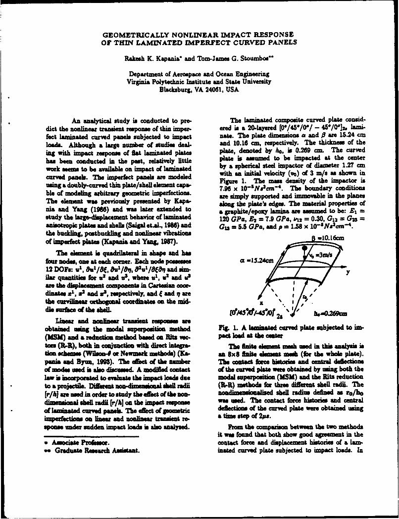
GEOMETRICALLY NONLINEAR IMtPACT RESPONSE
OF THIN LAMINATED IMPERFECT CURVED PANELS
Rakesh K. Kapania and Tom-Jam.. G. Stoumbos**
Department of Aerospace and Ocean EngineeringVirginia Polytechnic Institute and State University
Blacksburg, VA 24061, USA
An analytical study is conducted to pre- The laminated composite curved plate consid-dict the nonlinear transient response of thin inpr. ered is a 20..layered [00/45*/0*/ - 45*/0*]2, lami-feact laminated curved panels subjected to impact naew. The plate dimensions a and P awe 15.24 cmloads Although a large number of studies dteal, and 10.16 cm, respectively. The thickness of theing with mmpat, response of fA" laminate plates plate, denoted by ho, is 0.269 cm. The curvedhas been conducted in the past, relatively little plate is assumed to be impacted at the centerwork aseems to be available on impat of laminated by a spherical steel impactor of diameter 1.27 cmcurved panels. The imefect panels we modeled with an initial velocity (vo) of 3 rn/s as shown in
usin a ouby-crve thn pateshel eemet cpa-Figure 1. The mass density of the impactor isusig adoulycured hi plte/hel elmen caa-7.96 x 10⁻⁵N. 2crW'. The boundary conditions
ble of modeling arbitrary geometric imperfections. are simply supported and immovable in the planesThe element was previously presented by Kapa- along the plate's edges. Thle material properties ofnia and Yang (1966) and was later extended to a graphite/epoxy lamina are assumed to be: EA =study the large-dipaement behavior of laminated 120 GPa, A = 7.9 GPa, L'12 = 0.30, G12 = G23 =anisotropic plates and shells (Saigal et~l&, 1986) and Ga. =5.5 GPa, and p = 1.8 x 10 5 Naecm'.the bucdling, postbuckling and nonlinear vibrations =01cof impefec plates (Kapania and Yang, 1987.
The element is quadrilateral in shape and has v 3/four nodes, one at each corner. Each node possesses a-52c12 DO~s: in1 , OUL/84., &1/8%p 82tal/8489 and sim-Hua quantities for U2 and U3, where U1, V2 and U33
awe the displacement componets in Cartesian cooir.dinates x', x2 and x3, respectively, and f and 9 arerthe curvilinea orthogonal coordinates, on the mid- xdle surac of th f/4hf-4'o 2' - he-0.269cm
Linar and nonlinear transient respones wre ^W'Mf2obtained using the modal superposition method Fig. 1. A laminated curved plate subjected to in-(UMW and a reduction method based on Rita vac- pacd load at the Cint
toes (It-R), both in camiunctios with direct intepra- The finite eluunt, mesh used in this analysis istics schemnes (Wilson4 at Newnark methods) (K&s- an 8x8 fiite demutd mesh (for the whole plate).penis and Syan, 190). The eFoofeta the number The contaed farce historie and central defiectionsof modes modeds also discussed. A modified contact of the curved plate were obtained by using both thelaw in incorporated to evaluate the hmpaet loads due modal superposition (MSM) and the Ritz reduction
* ~to a projectile. Difterat non -!iesa shel radii (RL-R) methods for three diffret shell radii. The(rib] are used in order to study the effect of the non- *od - hedl radius defined as ro/hodimensional shell radii [r/hj on the impct repoins was used The contact force histories and centra
* of lamnnated curved pankels. The effec of guometric Ideflectons of the curved plate were obtained using.I;ImPrfetoms as linear and noliear transient ma a time step of 2pa.spai under sudden imspact loads as also analyzed. From the comparison betwe the two methods
______________it was found that both show good agreement in the*Associate Professor. contact force and displaemnt histories of a lam-seGraduate Research Assistant. inated curved plate subjected to impact loads. In
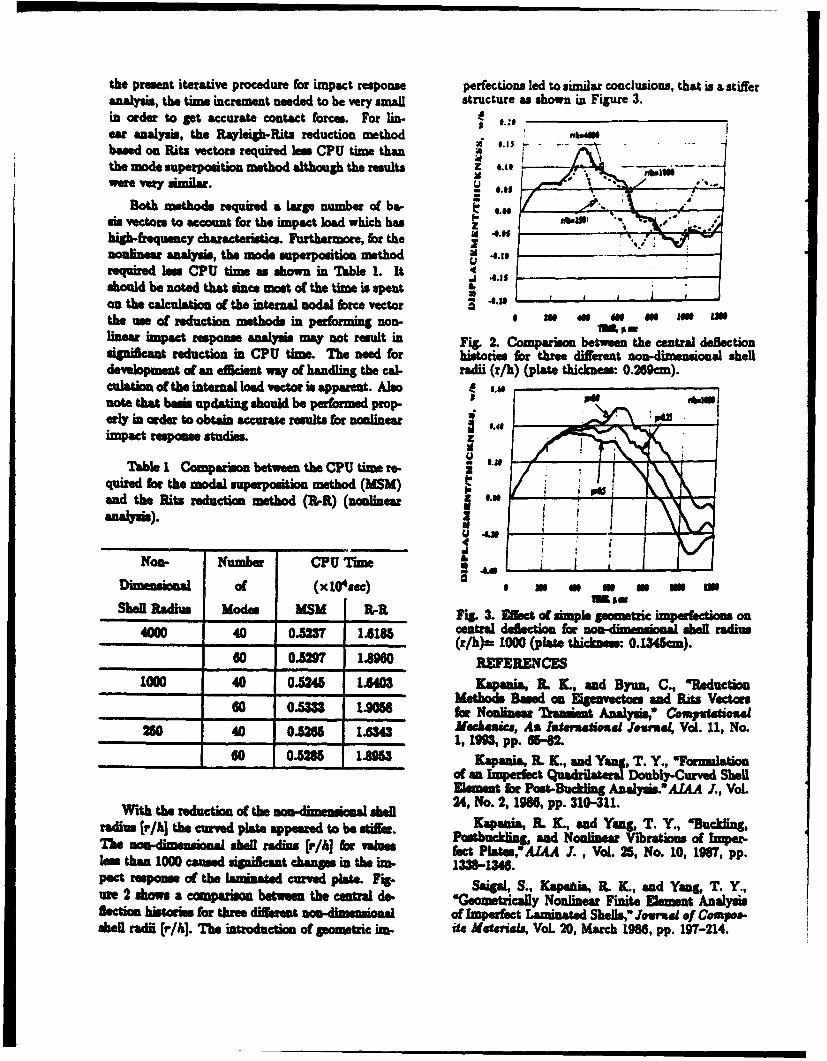
the present iterative procedure for impact response perfections led to similar conclusions, that is a stifferanalysis, the time increment needed to be very small structure as shown in Figure 3.in order to get accurate contact forces. For lin- e____________ear analysis, the Rayleighb-Ritz reduction methodbased on Ritz vectors required less CPU time thanthe mode superposition method although the results 4 .14 -
were very similar.
Both methods required a large number of ba- L osis vectors to account for the impact load which has zhigbh-fequency chrceIscs Furthermore, for thenonlinear analysis, the mode superposition method erequired less CPU time se shown in Table 1. It
A1 8.1sshould be noted that sauce most of the t=m is spent 1
on the calculation of the internal nodal force vectorathe use of reduction methods in performing non- I W W Ws M Uplinear impact response analysis may not result in Fig. 2. Comparison between the central deftectionsignific-an reduction in CPU time. The need for histories for three different no.-ie &Ioa shell
dvelopment of an efficient way of handling the cal- radi (n/h) (plate thickness: 0.269cm).culatio of the internal load vector is apparent. Also 1.cenote that basis updating should be performed prop-arly in order to obtain accurate results for nonlinear PCimpact response studies.
Table I Comparuon between the CPU time re- Iquired for the modal superposition method (MSM) 5
and the Ritz reduction metod (R-R) (nonlinear
NoO- Nubr CPU Tlime 4.
Dimensional Of (X10 4.ec) I 6 Mn 4W U
Shel Raius ode MSM U-UFig. 3. Efflect of simple geometric imperfctions on400 0 A 1615cenitral deflection for n-dm soalshell radius4000 40 0.5237(r/h)= 1000 (plate thickness: 0.134cm).
_______ 60 0.=9 1.sm6 REFERENCES
1000 40 0.524 1*40 Kapamia IL IL, and Byan, C., 'Reduction- ~Methods Baned on Elgenvectou. and Rits Vectors
_________ 60 0.533 ism0 for Nonlinear Transient Analysi, Conpxtstia250 40 0.526 -A Mwckeascp, An Internationaul Jeura Vol. 11, No.
1.6343 1, tIM, pp. 65-62.______ 60 0.528 185m Kapamia R. K., and Yang, T. Y., -Fourmulation
- ~of an Imperfect Quadrilateral Doubly-Curved ShellElement for Post-Duckling Analysis.-AIAA J., VoL
With the reducto of the n- e S henl-~ 24,, No. 2,198M, pp. 310-311.radius [v/h] the carved plate appeared to be stiffe. Kapania, IL K., and Yang, T. Y., -Buckln&
The hel raiusfr/h fo vauesPostbuckling, and Noulnezwa Vibrations of Imper-The omuonalshel rdiusfr/] fo vauesfect Plate@,'AIAA J. , Vol. 25, No. 10, 1967, pp.les than 1000 caused significant changes in the im. 133-134.pact re1sp mose1 of the laminated curve plate. Fig. SagW S., Kaas IL K, and Yang, T. Y.,woe 2 shws a comparison between the central de'Geometrically Nonlinear Finite Element AnalysisSlection histories for three dfiferent ondssoalOf Imperfect Laminated SeISls", Jom.L Of COupS.-shell radii (v/hI. The introduction Of geometric ink- ite Mgttisdi, Vol. 20, March 1988, pp. 197-214.
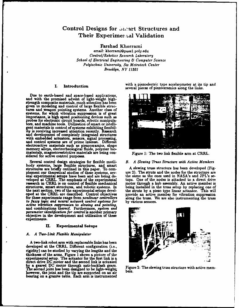
Control Designs for 0h1-art Structures andTheir Experimer tal Validation
Farshad Khorramiemail: [email protected]
Control/Robotics Research LaboratorySchool of Electrical Engineering &1 Computer Science
Polytechnic University, Six Metrotech CenterBrooklyn, NY 11201
with a piezoelectric type accelerometer at its tip andI. Introduction several pieces of piezoceramics along the links.
Due to earth-based and space-based applications,and with the promised advent of light-weight high-strength composite materials, much attention-has beengiven to modeling and control of large flexible struc-tures and weapon pointing systems. Another class ofsystems, for which vibration suppression is of greatimportance is high speed positioning devices such asprobes for electronic circuit boards, robotic manipula-tors, and machine tools. Utilization of smart or intelli-gent materials in control of systems exhibiting flexibil-ity is receiving increased attention recently Researchand development of completely integrated structureswith embedded actuators, sensors, signal processing,and control systems are of prime interest. Differentelectroactive materials such as piezocera-mics, shapememory alloys, electrorheological fluids, polymer bio-materials, mapnetorestrictive materials are being con- Figure 1: The two link flexible arm at CRRL.sidered for active control purposes.
Several control design strategies for flexible mutli- B. A Slewing Truss Structure with Active Membersbody systems, large flexible structures, and smartstructures are briefly outlined in this paper. To com- A slewing truss structure has been developed (Fig-plement our theoretical studies of these systems, sev- ure 2). The struts and the nodes for the structure areeral experimental setups have been and are being de- the same as the ones used in NASA's and JPL's se-veloped at CRRL. The emphasis of the experimental tups. One of the nodes is attached to a direct driveresearch in CRRL is on control of flexible mechanical motor through a hub assembly. An active member isstructures, smart structures, and robotic systems. In being installed in the truss setup by replacing one ofthe next section, two of the experimental setups devel- the struts by a piezo type linear actuator. This willoped at the CRRL are described. Control objectives provide an active member for vibration suppressionfor these experiments range from nonlinear controllers along the truss. We are also instrumenting the trussto fuzzy logic and neural network control systems for by various sensors.active m•rseton asppression to alewing and pointingand combinations thereof. Furthermore, system andparameter identification for control is another primaryobjective in the development and utilization of theseexperiments.
UL Experimental Setups
A. A Two-Link Flezible Manipulator I .
A two-link robot arm with replaceable links has beendeveloped at the CRRL. Different configuration (i.e., .. P"rigidity) can be studied by varying the lengths and the .thickness of the arms. Figure 1 shows a picture of the
_experimental setup. The actuator for the first link is adiiect drive DC motor and the second link is actuatedVha geared DC motor through anti-backlash gears.
h scond joint has been designed to be liht-weight. Figure 2: The slewing truss structure with active mem-however, the joint, and the tip are supported on an air bers.bearing on a granite table. Each arm is instrumented

P-VAdsufi. ft-..
I ' Ii~j 1 _____________________________
.44 SI LS 3
Figure 3: Open and closed-loop responses. Figure 4: Architecture of the fuzzy adaptive controller.
MI. Control Design Methodologies C. Fuzzy Logic Adaptive Control
Fuzzy controllers are based on three well knownstages: 1) the fuzzification stage, 2) the rule base stage,
A. Adaptive Nonlinear Control and 3) the defuzzification stage. First, the partition-
ing of the fuzzy input space is carried out and theFlexible articulated structures are nonlinear dis- corresponding membership functions of the fuzzy sets
tributed parameter systems. It is well known that the are assigned. Thereafter, the system parameters in-vibrational frequencies of such systems are geomet- volved must be identified and their membership val-ric configuration dependent. Therefore, linear based ues in the fuzzy input sets evaluated (fuzzification).control designs tend to be conservative to accommo- We have developed a technique utilizing a fuzzy ruledate for such variations. We have developed nonlinear base to switch among several controllers designed forbased control designs to significantly reduce the fre- different operating regimes and/or different parameterquency variations due to geometric configuration. This sets. The technique utilizes a real-time system identi-scheme is based upon asymptotic expansions on the fication algorithm during the fuzzification step. Anynonlinear distributed parameter dynamics. Further- parameter estimation method may be employed to ob-more, nonlinear adaptive controllers have been con- tain the unknown parameters or variables. The overallsidered to guarantee robust performance in presence structure of the scheme is depicted in Figure 4.of parametric perturbations.
D. Neural Network ControlB. Decentralized Control
Artificial Neural Networks (ANNe) have shownBy definition of a smart structure, sensors, actu- great potential for adaptive control applications due to
ators, signal processing, and control algorithms are their capability to learn the unmodeled system char-embedded in a smart structure. We will refer to a acteristics through nonlinear mappings. This featurecollection of sensors and actuators and the associated is desirable in the smart structures due to the inherentsignal processing and control algorithm as a "smart nonlinearities of the system. We are currently utiliz-patch." In envisioned smart structures, many smart ing a multi-layer feedforward neural network with apatches may be utilized to perform different tasks and Trajectory Pattern Method (TPM) for identificationtherefore these systems will exhibit a decentralized in- . and trajectory tracking of nonlinear systems (espe-formation structure. Therefore, it is highly desirable cially non-minimum phase systems). The TPM uti-to have decentralized control strategies meaning that lizes specific time functions for generation of feedfor-each smart patch in the system will have its own de- ward signals. The neural network is advocated to re-cision making rules and algorithms. This is highly de- duce the trajectory error by optimizing the appropriatesirable for the following reasons: 1) No need for in- parameters such as base harmonics in the TPM. Theformation transfer among "smart patches," 2) Fault training algorithms used for the networks are the backtolerant, i.e., failure of one "smart patch" does not propagation technique and the genetic algorithms.cause the failure of the overall system, and 3) Ease ofreal-time computational load on each subsystem.
We are currently pursuing decentralized control IV. Acknowledgementstrategies for the systems under consideration. A typ-ical response of the advocated controllers to suppress This work is supported in part by the U.S. Armyvibrations of a slewing beam is given in Figure 3. The Research Office under grant # DAAHt4-93-G-0209.beam has surface-mounted piezoceramics as sensorsand actuators.
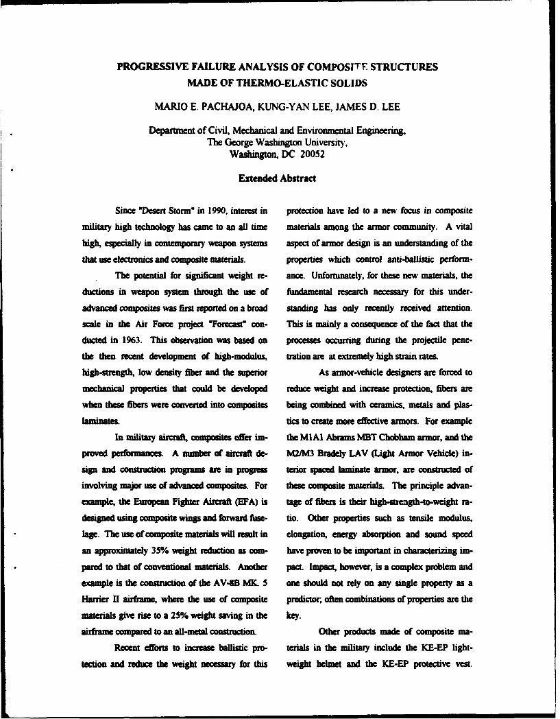
PROGRESSIVE FAILURE ANALYSIS OF COMPOSITE STRUCTURES
MADE OF THERMO-ELASTIC SOLIDS
MARIO E. PACHAJOA, KUNG-YAN LEE, JAMES D. LEE
Department of Civil, Mechanical and Environmental Engineering,The George Washington University,
Washington, DC 20052
Extended Abstract
Since *Desert Storm" in 1990, interest in protection have led to a new focus in composite
military high technology has came to an all time materials among the armor community. A vital
high, especially in contemporary weapon systems aspect of armor design is an understanding of the
that use electronics and composite materials. properties which control anti-ballistic perform-
The potential for significant weight re- ance. Unfortunately, for these new materials, the
ductions in weapon system through the use of fundamental research necessary for this under-
advanced composites was first reported on a broad standing has only recently received attention.
scale in the Air Force project 'Forecast" con- This is mainly a consequence of the fact that the
ducted in 1963. This observation was based on processes occumng during the projectile pene-
the then recent development of high-modulus, tration are at extremely high strain rates.
high-strength, low density fiber and the superior As armor-vehicle designers are forced to
mechanical properties that could be developed reduce weight and increase protection, fibers are
when these fibers were converted into composites being combined with ceramics, metals and plas-
laminates. tics to create more effective armors. For example
In military airaVf composites offer im- the MIAI Abrams MBT Chobham armor, and the
proved performances. A number of aircraft de- M2/M3 Bradely LAV (Light Armor Vehicle) in-
sign and construction programs are in progress terior spaced laminate armor, are constructed of
involving major use of advanced composites. For these composite materials. The principle advan-
example, the European Fighter Aircraft (EFA) is tage of fibers is their high-stuength-to-weight ra-
designed using composite wings and forward fuse- tio. Other properties such as tensile modulus,
lage. The use of composite materials will result in elongation, energy absorption and sound speed
an approximately 35% weight reduction as com- have proven to be important in characterizing im-
pared to that of conventional materials. Another pact. Impact, however, is a complex problem and
example is the construction of the AV-8B MK. 5 one should not rely on any single property as a
Harrier H airframe, where the use of composite predictor, often combinations of properties are the
materials give rise to a 25% weight saving in the key.
airframe compared to an all-metal construction. Other products made of composite ma-
Recet efforts to increase ballistic pro- terials in the military include the KE-EP light-
tection and reduce the weight necessary for this weight helmet and the KE-EP protective vest.

However. very likely the most important applica- failure analysis which is the third case available
tion can be in the next generation -Rail Gun" within COMPASS. All elements assume linear
weapon system. of which the "rail" part that plays stress-strain-temperature relations. Failure of a
a critical role could be made of composite. composite element is determined by using
The increasing use of composites in the Hashin's failure criterion, while the failure of an
military field, as well as in the aerospace, marine, isotropic elements is determined by using the von
and automotive fields, has spurred great interest Mises failure criterion. The solution process
in developing numerical tools to optimize designs involves increasing the original load until an
made of composite materials. Laminated compos- element fails. The element that failed is classified
ites, by their nature, are heterogeneous and ani- as being isotropic or composite. Furthermore,
sotropic. This makes the failure characteristics of composite element failure is identified as being in
the composite materials more complicated than fiber or matrix mode. The stiffness, the heat
that of the isotropic materials. Only in the most conductivity, and the thermal expansion matrices
recent years, the finite element technique together of that element are then altered according to the
with the high capacity and high speed of modem mode of failure. As a consequence, the stresses
computers have made it possible to analyze fiber and the temperature in the entire structure are
reinforced composites in detail. redistributed. The structure is then analyzed with
Some weli-known commercial finite ele- the set of matrices to determine if any further fai-
mern codes are capabl to a limited degree, of lure is induced. If further failure does not occur,
analyzing composite structures. However, few the load is increased to the level needed to cause
programs attempt to perform a complete thermo- the next element to fail. This incremental process
mechanical failure analysis of composite suc- continues until catastrophic failure occurs. Thetues. Recently, under a grant from the NASA ultimate load carrying capacity of the structure is
Goddard Space Flight Center, a general purpose then determined.
thermo-mechanical finite element program, called The constitutive relations of anisotropic
COMPASS (COMPosite Analysis of Structural thermo-visco-elastic solid, the failure criteria and
Systems), was developed for the analysis of com- post-failure material behavior, and the finite ele-
posite structures. Three main solution sequences mea formulation of composite structures made of
are offered by the code, namely: 1) non-linear- thermo-mechanical solids are presented. Also, for
static stress analysis, 2) delamination growth illustrative purpose the procedures and the nu-
analysm 3) proessive failure analysis. merical results of the progressive failure analysis
Focus of this work is on the p of a composite plate are discussed in detail.
Paper for Army Research office Workishop on:
DYNAMIC RESPONSE OF COMPOSITE STRUCTURES
ABSTRACT
Title: Damage and Energy Exchange From Impact At Super-Perforation VelocitiesOn Carbon Fiber Epoxy Composite Plates By Rigid Sphere Projectiles
Authors Arnold H. Mayer, Flight Dynamics Directorate, Vright Laboratory,VPAFB, ON
Summary travelling with velocity vectorscontained within a small cone of the
An extensive experimental program to axis. Projectile velocity wasinvestigate the damage and energy measured ahead of the target plateexchange which accompany the by means of a set of fine trip wiresballistic impact and penetration by of known separation distance byrigid spherical steel projectiles of noting the instants of break ofcarbon fiber epoxy composite plates electrical continuity and behind theabove their penetration threshold target by two sets of inductionhas been conducted . Now coils of known location along thesignificant findings concerning pipe axiv which wore wrapped aroundthese impact phenomena are the outer cylindrical surface of thedescribed. Preliminary applied plastic pipe. Thus the energymechanics analyses that serve for imparted by the projectile to thetheir explication or correlation are target material could be computed.derived. Some experiments were performed
without the adhesive paper and theloose fragments collected in the
Description of the Experimental plastic pipe were swept together andProgram weighed and compared with the weight
loss of the target plates. A singleThe experimental program set of plates consisting of plates
consisted of firing one-half inch which had been penetrated atdiameter rigid spherical steel different velocities were stainedprojectiles at carbon fiber epoxy with Gold Chloride, pyrolysed in anmatrix composite plates which were air oven, deplied with a scalpel,clamped between steel plates mounted on a rigid, backing andcontainning a 3 inch diameter subjected to measurement of thecircular hole with the design impact areas of the penetration hole and ofpoint located at its center. The the envelope of surroundingcomposite target plates were 32 gold-stained delaminateod aresa. Thisplies thick layed up in balanced was done with the aid of automaticquasi-isotropic stacking image analysis equipment. It wyaarrangements consisting of 0, 45, thus possible to obtain the shapesand 90 degree fiber orientations and and distribution of hole andalso in balanced spiral staircase dolaminated areas on each ply oflayups in which the fibre direction panels penetrated at differentincreased in increments of 90, 45, velocities over the range of 200 to22.5, or 11.25 degrees from ply to 6000 feet per second. An additionalply. Ten inch diameter rigid novel measurement was made of theplastic cylinders with axes total surface and internal fracturecoincident with the shotline were area which communicates with thelined with adhesive paper and placed surface by employing a surface areaflush with the front and rear target measurement apparatus based on thesupport plates in order to catch gas adsorbtion technique withspall fragments emanating from the Nitrogen as the adsorbent gas.target plate. Circular end platescontaining a small central hole topermit uninterrupted passage of the Principal Findingsprojectile were also covered withadhesive paper to catch fragments 1. Energy exchange between
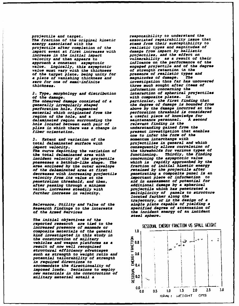
projectile and target. responsibility to understand theThe fraction of the original kinetic associated repairability issue thatenergy associated with the stems from their susceptibility toprojectile after completion of the realistic types and magnitudes ofimpact event at first increases with damage from impact by ballisticincrease In the initial impact projectiles, and the effect onvelocity and then appears to vulnerability as a result of theirapproach a constant asymptotic influence on the performance of thevalue. Logically, this asymptotic engaged projectile and of the degreevalue must vary with the thickness of strength retention in theof the target plate, being unity for presence of realistic types anda plate of vanishing thickness and magnitudes of damage. Thezero for one of semi-infinite investigation thus far has uncoveredthickness, three smuch sought after items of
information concerning the2. Type, morphology and distribution interaction of spherical projectilesof the damage. with composite plates. InThe observed damage consisted of a particular, the first finding thatgenerally irregularly shaped the degree of damage is bounded fromperforation hole, fragmented above by the damage incurred at thematerial which originated from the perforation threshold is consideredregion of the hole, and a a useful piece of knowledge fordelaminated region surrounding the maintenance personnel. A secondhole located between each pair of relevant finding is theplles in which there was a change in understanding gained from thefiber orientation. present investigation that enables
one to infer the form of the3. Extent and variation of the momentum interchange withtotal delaminated surface with projectilies in general and whichimpact velocity. consequently allows correlation ofThe curve depicting the variation of the thresholds for various types ofthe total delaminated are* with functioning. Thirdly, the findingincident velocity of the projectile concerning the asymptotic valuepossesses a bathtub-like shape. The which is rapidly approached by thearea enclosed by the outer envelope fraction of initial kinetic energyof the dejaminated area at first retained by the projectile afterdecreases with increasing projectile penetrating a composite panel is anvelocity from its value at the important piece of information topenetration threshold, and then, aid in assessment of potential forafter passing through a minimum additional damage by a sphericalvalue, increases steadily with projectile which has penetrated afurther increase in velocity, multiplicity of panels to structure
located farther along thetrajectory, or in the design of a
Relevance, Utility and Value of the single plate capable of yielding aResearch Findings to the interests specified degree of attenuation ofof the Armed Services the incident energy of an incident
steel sphere.The initial objectives of thereported research are tied to theincreased presence of manmade or RSID. ERY FKION U SPALL IGHTcomposite materials of the general 1.0 - I
kind investigated in this study inthe construction of military .
vehicles and weapon platforms as a • 0.8result of now well recognized 0 ostructural efficiency advantages Coosuch as strength to weight ratio and , 0.6potential tailorability of strengthin required directions toaccommodate the directionality of ' 0.4 1imposed loads. Decisions to employ I
new materials in the construction ofmilitary materiel entail a -0.2
0.0 . " . . .. .0.0 0.5 1.0 1.5 2.0 2.5 3.0
SPAt LF_-GHT 11S
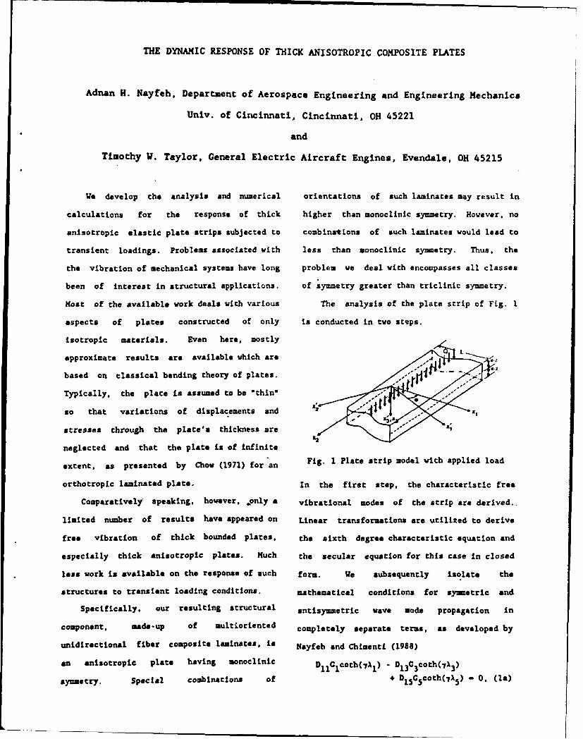
THE DYNAMIC RESPONSE OF THICK ANISOTROPIC COMPOSITE PLATES
Adnan H. Nayfeh, Department of Aerospace Engineering and Engineering Mechanics
Univ. of Cincinnati, Cincinnati, OH 45221
and
Timothy W. Taylor, General Electric Aircraft Engines, Evendale, OH 45215
We develop the analysis and numerical orientations of such laminates may result in
calculations for the response of thick higher than monoclinic symmetry. However. no
anisotropic elastic plate strips subjected to combinations of such laminates would lead to
transient loadings. Problems associated with less than monoclinic symmetry. Thus, the
the vibration of mechanical systems have long problem we deal with encompasses all classes
been of interest in structural applications, of symmetry greater than triclinic symmetry.
Most of the available work deals with various The analysis of the plate strip of Fig. I
aspects of plates constructed of only is conducted in two steps.
isotropic materials. Even here, mostly
approximate results are available which are
based on classical bending theory of plates.
Typically, the plate is assumed to be *thin'
so that variations of displacements and
stresses through the plate's thickness are * '
neglected and that the plate is of infinite
extent, as presented by Chow (1971) for*an Fig. 1 Plate strip model with applied load
orthotropic laminated plate. In the first step, the characteristic free
Comparatively speaking, however, jonly a vibrational modes of the strip are derived..
limited number of results have appeared on Linear transformations are utilized to derive
free vibration of thick bounded plates, the sixth degree characteristic equation and
especially thick anisotropic plates. Much the secular equation for this case In closed
less work is available on the response of such form. We subsequently isolate the
structures to transient loading conditions. mathematical conditions for symmetric and
Specifically, our resulting structural antisymmetric wave mode propagation in
component, made-up of aultioriented completely separate terms, as developed by
unidirectional fiber composite laminates, is Nayfeh and Chimenti (1988)
an anisotropic plate having monoclinic D1 1Clcoth(,rl) - D1 3C3coth(71 3 )
symmetry. Special combinations of + D15 %Gcoth(7A 5 ) - 0. (la)
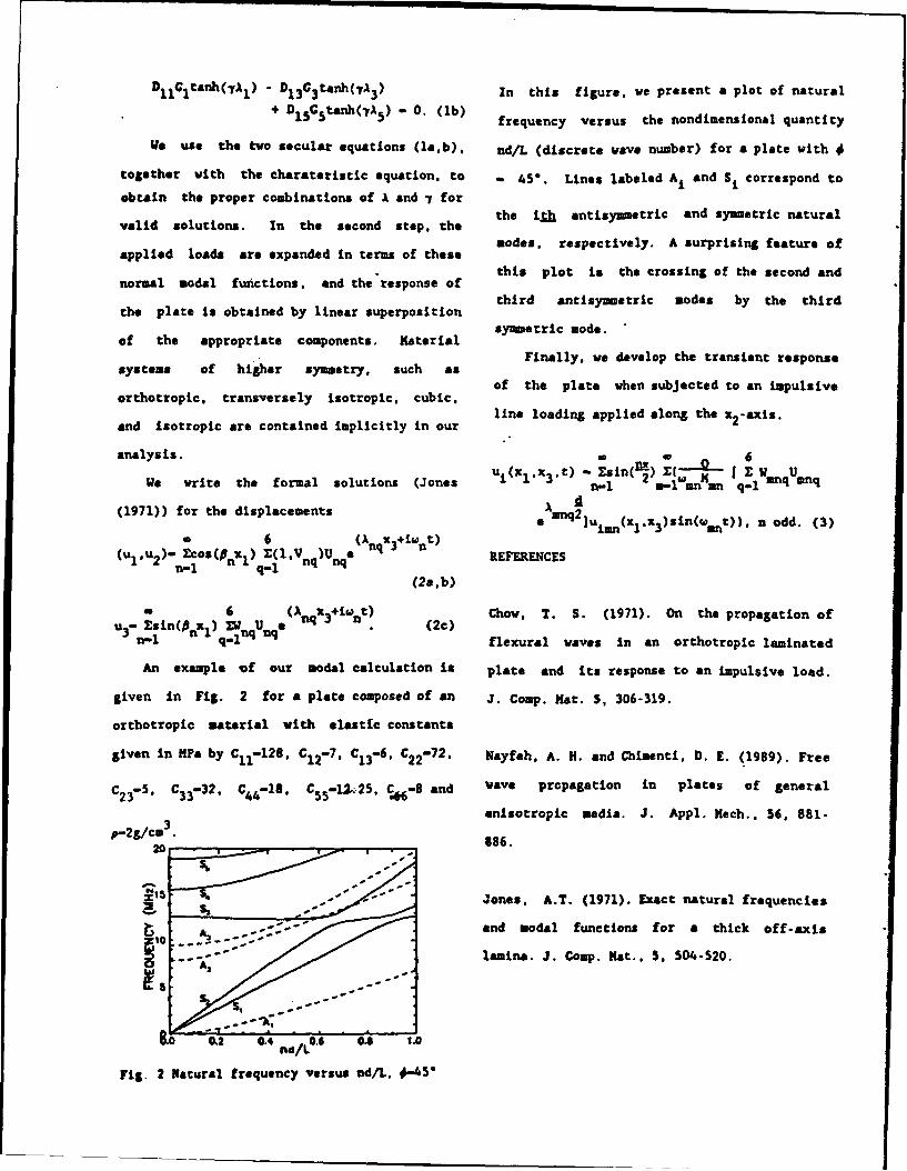
S11 Itanh(-yA) I D1 3G3 tanh(7 A3 ) In this figure. we present a plot of natural
+ D1 5 C5tanh(y13 ) - 0. (lb) frequency versus the nondimensional quantity
WO use the two secular equations (la,b), nd/L (discrete wave number) for a plate with #
together with the charateristic equation, to - 5*. Lines labeled AI and SI correspond to
obtain the proper combinations of A and 7 for
valid solutions. In the second step, the the ith antisymmetric and symmetric natural
applied loads are expanded in terms of these nodes, respectively. A surprising feature of
normal modal functions. and the'response of this plot is the crossing of the second and
the plate is obtained by linear superposition third antisymmetric modes by the third
of the appropriate components. Katerial symmetric mode.
Finally, we develop the transient responsesystems of higher symmetry, such as
of the plate when subjected to an impulsiveorthotropic, transversely isotropic, cubic,
and isotropic are contained implicitly in our line loading applied along the z2-axis.
analysis. - i 6u(x,, t)- sin(lu*_) X(-• -We write the formal solutions (Jones (xlx 3 ,t) n-1 2 , anMmn Z q-mnq nq
(1971)) for the displacements Amnq2eo nq]u1mn(x 1 ,x 3 )sin(wnnt)), n odd. (3)
a 6 (A x.+iW t)(u.,u 2 )- Ecos(n x ) X(IV )U nq n REFERENCES
n-1 n 1 q- nq nqE(2a,b)
6 (Anq X3+i int) Chow, T. S. (1971). On the propagation ofu- sin( x.)d U • "e . (20)Sn-1 n 1 qlnq nq flexural waves in an orthotropic laminated
An example of our modal calculation is plate and its response to an impulsive load.
given in Fig. 2 for a plate composed of an J. Comp. . at. 5, 306-319.
orthotropic material with elastfc constants
given in •Pa by C1 1i128. C1 2 -7. C1 3-6, C2 2-72. Nayfeh, A. H. and Chimenti, D. E. (1989). Free
C2 3-5. C3 3-32, C4 4 -18, C5 5 -12.2,25, -8 and wave propagation in plates of general
anisotropic media. J. Appl. Hech., 56, 881-
p-2g/cm 886.
S- -- Jones. A.T. (1971). Exact natural frequencies
"and modal functions for a thick off-axis
lamina. J. Comp. Nat., S. 504-520.
8.0 0.2 0.4 nL0.6 04 1.0
Fig. 2 Natural frequency versus ad/L, #-4S'
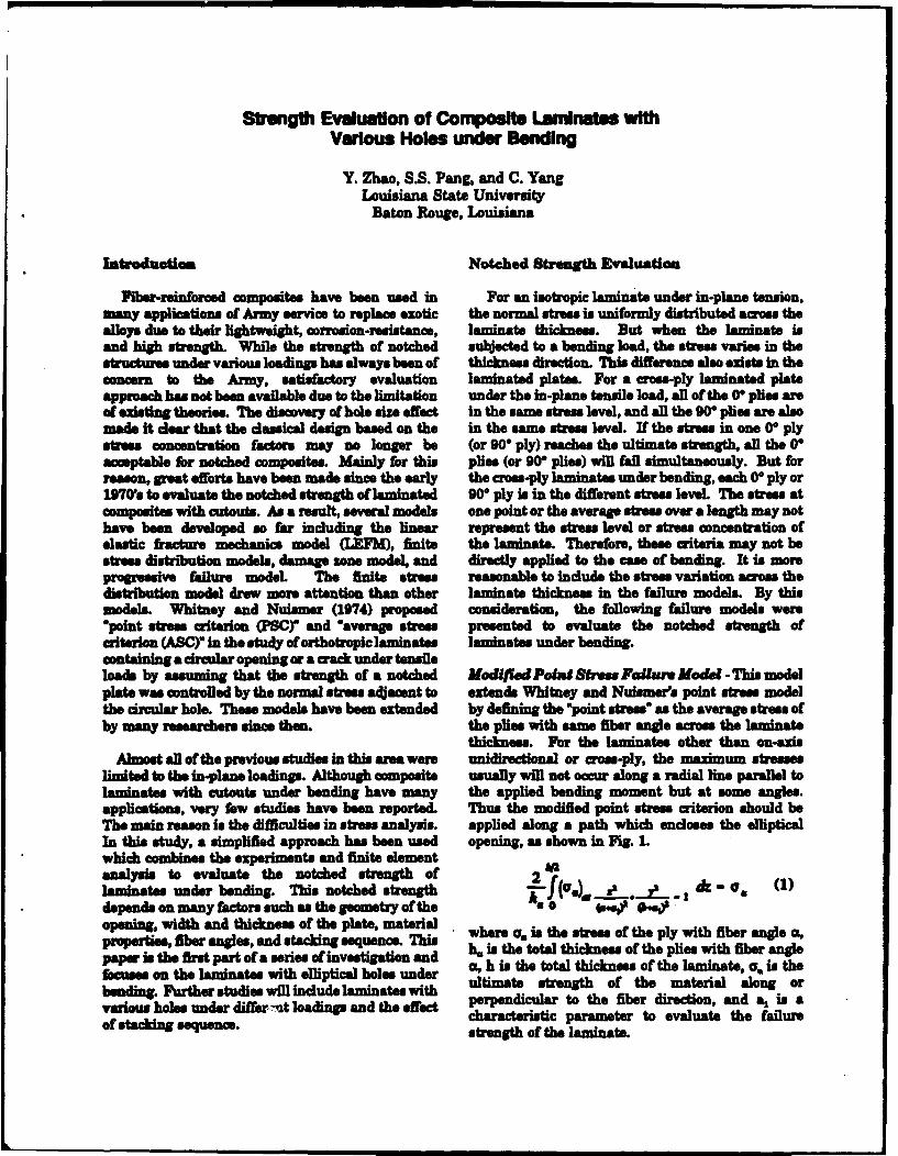
Strength Evaluation of Composlte Laninates withVarious Holes under Bending
Y. Zhao, SS. Pang, and C. YangLouisiana State University
Baton Rouge, Louisiana
Introduiotm Notched Strength Evaluation
Fiber-reinforced composites have been used in For an isotropic laminate under in-plane tension,many applications of Army sermce to replace exotic the normal stress is uniformly distributed across thealloys due to their lightweight, corrosion-resistance, laminate thickness. But when the laminate isand high strength. While the strength of notched subjected to a bending load, the stress varies in thestructures under various loadings has always been of thickness direction. This difference also exists in theconcern to the Army, satisfactory evaluation laminated plates. For a cress-ply laminated plateapproach has not been available due to the limitation under the in-plane tensile load, all of the 0V plies areof existing theories. The discovery of hole size effect in the same stress level, and all the 90" plis are alsomade it dear that the classical design baed on the in the same stress level. If the stress in one 0* plystress concentration factors may no longer be (or 90" ply) reaches the ultimate strength, all the 0"acceptable for notched composites. Mainly for this plies (or 90" plies) will fail simultaneously. But forreason, great efforts have been made since the early the crom-ply laminates under bending, each 0* ply or1970's to evaluate the notched strength of laminated 90- ply is in the different stress level The stress atcomposites with cutouts. As a result, several models one point or the average stres over a length may nothave been developed so far including the linear represent the stress level or stress concentration ofelastic fracture mechanics model (LEFMI , finite the laminats. Therefore, these criteria may not bestress distribution models, damage zone model, and directly applied to the case of bending. It is moreprogressive failure model The finite stres reasonable to include the stress variation across thedistribution model drew more attention than other laminate thickness in the failure models. By thismodels. Whitney and Nuismer (1974) proposed consideration, the following failure models were"point stress criterion (PSCY' and "average stress presented to evaluate the notched strength ofcriterion (ABC)* in the study of orthotropic laminates laminates under bending.containing a drcular opening or a crack under tensileloads by assuming that the strength of a notched Madif/W Pous Sbwes Failure Model -This modelplate was controlled by the normal stress adjacent to extends Whitney and Nuismer's point stress modelthe circular hole. These models have been extended by defining the "point stress" as the average stress ofby many researchers since then. the plies with same fiber angle across the laminate
thickness. For the laminates other than on-axisAlmost all of the previous studies in this area were unidirectional or cross-ply, the maximum stresses
limited to the in-plane loading@. Although composite usually will not occur along a radial line parallel tolaminates with cutouts under bending have many the applied bending moment but at some angles.applications, very few studies have been reporte& Thus the modified point stress criterion should beThe main reason is the difficulties in stress analysis. applied along a path which encloses the ellipticalIn this study, a simplified approach has been used opening, as shown in ft. Lwhich combines the experiments and finite elementanalysis to evaluate the notched strength of 2laminates under bending. This notched strength A _ dc(depends on many factors such as the geometry of the s 404)0 4.|opening, width and thickness of the plate, materialproperties, fiber angies, and stackin equence. This where . is the stress of the ply with fiber angle a,paper is the first part of a series of investigation and h, is the total thickness of the plies with fiber anglefocuses on the laminates with elliptical holes under u, h is the total thickness of the laminate, ia is thebending. Further studies will include laminates with ultimate strengh of the material along orvarious holes under diffeunt loadings and the effect perpendicular to the fiber direction, and at is acharacteritic parametr to evaluate the failureof staking sequence. stengthi of the laminate.
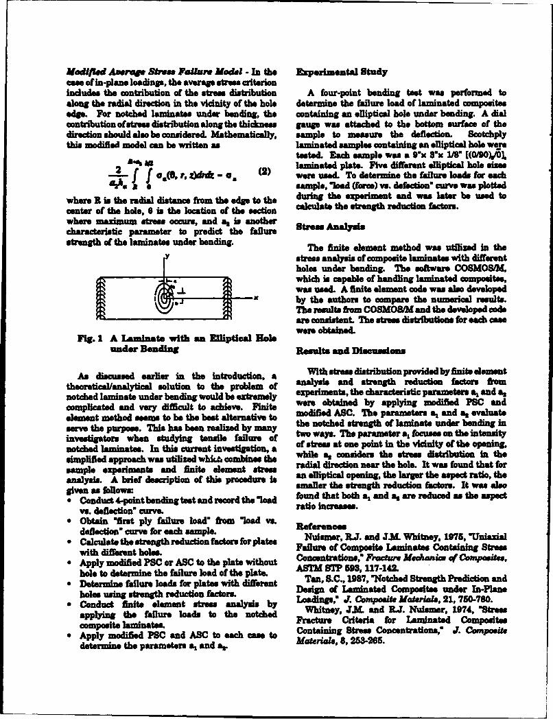
J7ModVWid Averaqg Sbuwe Pa/ul Model - In the Experimental Studyceo ofin-plane loadings, the average stress criterionincludes the contribution of the strew distribution A four-point bending test was performed toalong the radial direction in the vicinity of the hole determine the failure load of laminated compositesedge. For notched laminates under bending, the containing an elliptical hole under bending. A dialcontribution ofstress distribution along the thickness gauge was attached to the bottom surface of thedirection should also be considered. Mathematically, sample to measure the deflection. Scotchplythis modified model can be written as laminated samples containing an elliptical hole were
tested. Each sample was a 9"x 3'x 1/8" [(0/90)10O]
2 J laminated plate. Five different elliptical hole sizes;_ -f f were used. To determine the failure loads for each
sample, "load (framo) vs. defecon" curve was plotted
where R is the radial distance from the edge to the durin the experiment and was later be used to
center of the hole, 0 is the location of the section calculate the strength reduction factors.
where maximum strum occurs, and as is another Stress Analysischaracteristic parameter to predict the failurestrength of the laminates under bending. The finite element method was utilized in the
Y stress analysis of composite laminates with differentholes under bending. The software COSMOStM.which in capabl of handling laminated. compo~sites,was used. A finite element code was also developed
I -by the authors to compare the numerical results.The results fiom COSMOSM and the developed codeare consistent The stres distributions for ach casewere obtained.
Fig. 1 A Laduinate with an Elliptical Holeunder Bending Results and Discudons
thAsdiscussedearly ier in the introduction. a With stress distribution provided by finite element
tArsidice d earyt solution to the problem of analysis and strength reduction factors from
notched laminate under bending would be extremely experiments, the characteristic parameters a, and ascomplicated and very difficult to achieve. Finite were obtained by applying modified PSC and
element method seems to be the best alternative to modified ABC. The parameters a% and a, evaluate
s e the purpose. This has been realized by many the notched strength of laminate under bending in
investigators when studying tensile f&ur* o two ways. The parameter a% focuses am the intensity
notched laminates. In this current investigation, a of stress at one point in the vicinity of the opening,
simplified approach was utilized whiti combines the while , considers the strew distribution in the
sample experiments and finite element straw radial direction near the hole. It was found that for
analysis. A brief description of this procedure is an elliptical opening, the larger the aspect ratio, the
given as follows: smaller the strength reduction factors. It was also
"* Conduct 4-point bending test and record the found that both a, and a, are reduced as the aspect
vs. deflection" curve, ratio increases."* Obtain "first ply failure load" from 'load vs.
deflection' curve for each sample. Reerenes"* Calculate the strength reduction factors for plates Nuismer, R.J. and J.M. Whitney, 1976, 'Uniazial
with different holes. Failure of Composite Laminates Containing Stress
"* Apply modified PSC or ASC to the plate without Concntrations,' Fracture Mec&.nic of Compjosites,
hole to determine the failure load of the plate. ARM S'P 593, 117-142.
"* Determine failure loads for platee with different Tan, S.C., 1987, "Notched Strength Prediction and
holes using strength reduction factors Design of Laminated Composite. under In-Plane
"* Conduct finite element strses analysis by Loadings,' J. Composite Materials, 21, 750-780.
applying the failure loads to the notched Whitney, J.LM. and I.J. Nuismer, 1074, "Stres
ompoBiteClainates Fracture Criteria for Laminated Composites
" Apply modified PSC and ABC to each ea to Containing Stress Concentrations,' J. Composite
determine the parameters a, and a&. Materials, 8,253265.
Optimal Control of Infinite-Order Smart CompositeStructural Systems Using Distributed Sensors
Vittal Rao and Robert ButlerDepartment of Electrical Engineering and
Intelligent Systems CenterUniversity of Missouri-Rolla, Rolla, MO. 65401
ABSTRACT
The salient features of smart structures are order structural systems is examined that usesthe generation of internal forces for suppressing finite dimensional approximations to desiredvibrations, mode shape control and the spatially curvature and curvature rate kernels. Thesedistributed nature of the actuators and sensors. kernels are used for generating the shapes ofIn the conventional control design methodology, PVDF distributed sensors. The output of thesethe spatial distribution of sensors and actuators spatially distributed sensors will be utilizedis not taken into consideration. Recently, a directly as the control signal for suppressingnumber of researchers have proposed designing the structural vibrations.distributed control schemes for infinite-orderstructural systems using distributed sensors and A method for the calculation ofactuators. The main advantages of distributed distributed sensor shape functions wascontrol are (i) the ability to control all modes of presented by Miller and van Schoor in 1991.the structure thus eliminating spill-over A finite element model (FEM) of the systemproblems, (ii) trade-offs between gain margin was used to obtain a state space model of theand bandwidth of the controllers, and (iii) the structural system. With the use of the FEMuse of displacement, rotation and strain interpolation function, shape functionsmeasurements as feedback signals in the representing a continuous approximation toinfinite-order systems. The design and the discrete linear quadratic regulator (LQR)implementation of optimal control strategies for solution were determined. The shapeinfinite-order smart structures present functions were then transformed into thechallenging problems. One is the computational appropriate shape functions required for theeffort required to design optimal controllers for implementation with PVDF distributedinfinite-order structural models, and the other is sensors. This method is computationallythe development of optimally shaped distributed intensive and requires covering the entiresensors and actuators. A procedure for sensor structure with two distributed sensors for theshape optimization and the design of controllers implementation of the optimal controlfor simple cantilever beam test article has been solution. Also, only the LQR control designdeveloped and discussed in this paper. solution was demonstrated and the shape
functions were not verified with simulations.The smart materials polyvinylidene
fluoride (PVDF) and shape memory alloys can In order to verify the design methodbe utilized in the development of customized discussed above, simulations using thedistributed sensors. These sensors can be shaped distributed sensors were necessary. Initialto control the desired response of the structural simulations of the LQR controller using thesystem. For the implementation of optimal state space model of the structural systemcontrol strategies, we need to develop sensor were performed. The results of this simulationshape optimization techniques. In this paper, a were considered to be the standard by whichmethod for the design of controllers for infinite- the performance of the system with the
distributed sensors was evaluated. A second sensor. This method increases the amount ofsimulation of the system was performed to computation that must be done by the controlevaluate the distributed sensors. This was system, but it does allow for thedone by using the FEM interpolation function implementation of the desired control with ato calculate the distributed parameters of the distributed sensor covering a part of thestructure and the resulting response of the structure. The usefulness of a single relativelyspatially continuous distributed sensors. The small customized PVDF film sensor alongcomparison of the two simulations confirmed with an observer to provide full state feedbackthe shape function calculation of the information for the entire structure isdistributed sensors. examined. The complexity and performance of
the proposed control scheme is compared withThe calculation of the sensor shape the original distributed sensor implementation.
functions is a mathematically andcomputationally intensive process. In this Since smart structures exist in a varietyprocedure it is required to calculate of sizes and shapes and in various applications,displacement and displacement rate kernels, it is desirable to have many different controlThese kernels are then transformed into the design algorithms available to the controldesired kernels by the appropriate design engineer. For many of the potentialmathematical operations. For the PVDF applications, controller design methods othersensor implementation, this requires a double than the LQR may provide superiorintegration of the displacement kernel to performance. As a first step, a pole placementobtain the curvature kernel and a double controller was designed to determine if shapeintegration of the displacement rate kernel to functions for this controller could beobtain the curvature rate kernel. A method is calculated for the distributed sensors. Thepresented for the direct calculation of the shape functions obtained were satisfactorycurvature and curvature rate kernels. This indicating that state space controllers otherreduces the computation time required for the than the LQR may be implemented with thedistributed sensor shape optimization. distributed sensors.
Completely covering the members of a In summary, we have developed anstructure with two distributed sensors may be alternate method for computing curvature andpossible in a laboratory setting, but it may not curvature rate kernels in the development ofbe practical for a large structure with many optimized sensor shape functions andstructural elements and physical components. proposed a procedure for utilizing a partialA solution to this problem was found by using distributed sensor along with an observer fora relatively small part of one of the distributed the implementation of controllers. We havesensors along with an observer. The output of also examined various control methodologiesthe resulting distributed sensor provides a for designing distributed controllers. Theportion of the desired control signal. The usefulness of a single relatively smallobserver may be driven by the output of the customized sensor along with an observer toimplemented sensor providing the states of the provide full state feedback information isstate space model. The states may then be used demonstrated with simulation studies. We areto generate the missing part of the control in the process of implementing these sensorssignal that would be provided by the full and control algorithms on a simple cantilever
beam test -ticle.
ELECTRO-THERMO-MECHANICS OF SPRING-LOADED
CONTRACTILE FIBER BUNDLES WITH APPLICATIONSTO IONIC POLYMERIC GEL AND SMA ACTUATORS
Mohsen ShahinpoorIntelligent Materials, Structures & Systems Laboratory
College of Engineering
University of New Mexico
Albuquerque, New Mexico 87131
ABSTRACT
A mathematical model is presented Crowson and Anderson [2]. In the presentfor the dynamic response of contractile paper a mathematical model is presentedfiber bundles embedded in or around elastic for the dynamic response of contractilesprings that are either linear helical fiber bundles embedded in or around elasticcompression springs or hyperelastic springs springs that are either linear helicalsuch as rubber-like materials. The fiber compression springs or hyperelastic springsbundle is assumed to consist of a parallel such as rubber-like materials. Thearray of contractile fibers made form either proposed theory presents two differentcontractile polymeric muscles such as description of such processes for ionicpolyacrylic acid plus sodium acrylate polymeric gel fiber bundles andcross-linked with bisacrylamide (PAAM) shape-memory alloy fiber bundles.or polyacrylonitrile (PAN) fibers. The For the case of ionic polymeric gel fibersproposed model considers the electrically or the model consists of an encapsulatedpH--induced contraction of the fibers which hermetically sealed, helical compressionmay include resistive heating of the fiber in spring-loaded cylindrical linear actuatorscase of shape-memory allot 'he theory containing a counterionic solution orthen branches out to ' different electrolyte such as water+acetone, adescription of snich proceswb for ionic cylindrical helical compression spring and apolymeric gel fiber bundles and collection of polymeric gel fibersshape-memory alloy fiber bundles. (polyelectrolytes) such as polyvinyl alcohol
PVA) polyacrylic acid (PAA) orINTRODUCTION polyacrylamide. Furthermore, the helical
spring not only acts as a compressionIntelligent material systems and spring between the two hermetically sealed
structures have become important to all circular end-caps but contains snugly thedefense and civilian sectors of the society polymeric gel fiber bundle and also acts as(see Ahmad, Crowson, Rogers and Aizawa the cathode (anode) electrode while the[1]). Accordingly, based on such materials, two actuator end-caps act as the otherstructures and their integration with cathode (anode) electrodes. In this fashion,appropriate sensors and actuators, novel a DC electric field of a few volts perapplications, useful for all defense and centimeter can cause the polymer gel fibercivilian programs, have emerged. Numerous bundle to contract (expand). This causesexamples may be cited as can be seen from the compression spring to contract and pullkey reference articles such as [1] and the two end-caps closer to each other
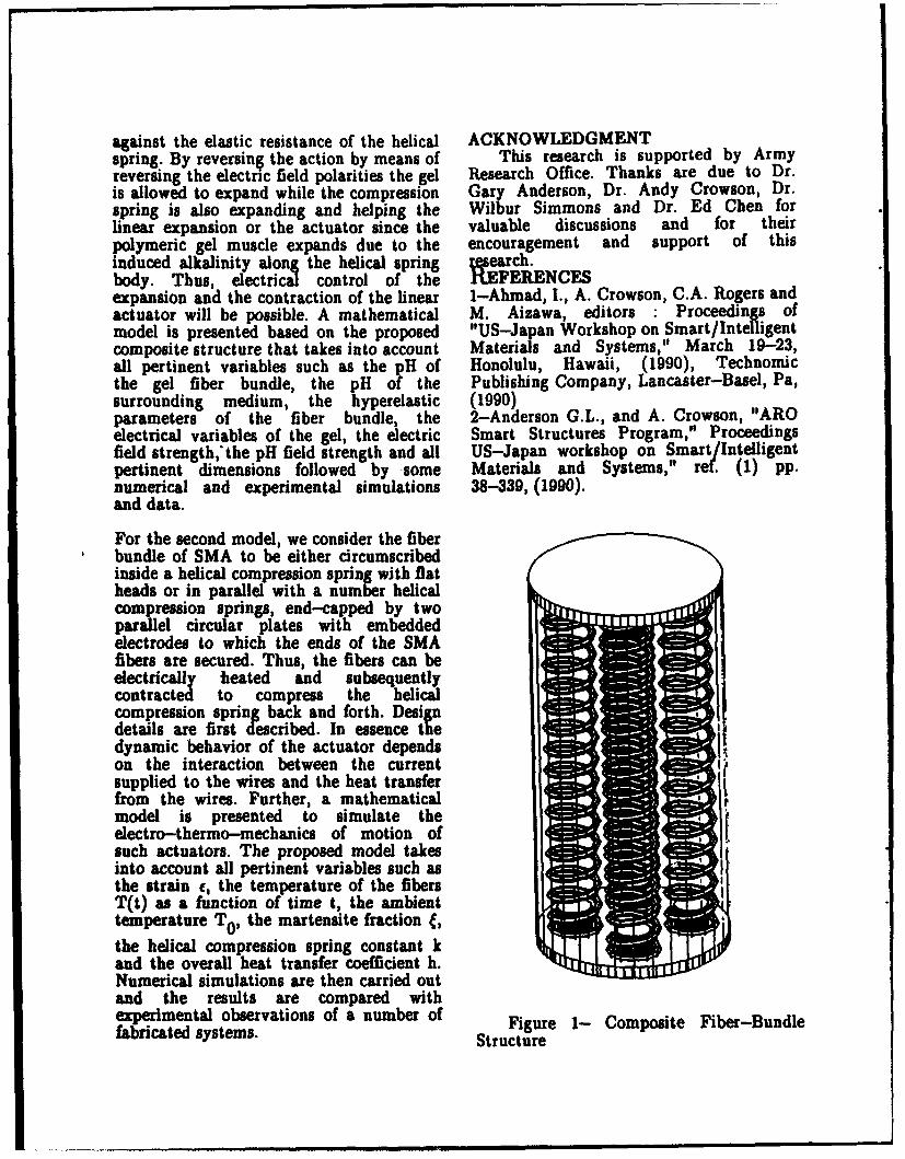
against the elastic resistance of the helical ACKNOWLEDGMENTspring. By reversing the action by means of This research is supported by Armyreversing the electric field polarities the gel Research Office. Thanks are due to Dr.is allowed to expand while the compression Gary Anderson, Dr. Andy Crowson, Dr.spring is also expanding and helping the Wilbur Simmons and Dr. Ed Chen forlinear expansion or the actuator since the valuable discussions and for theirpolymeric gel muscle expands due to the encouragement and support of thisinduced alkalinity along the helical spring raearch.body. Thus, electrical control of the IIXFERENCESexpansion and the contraction of the linear 1-Ahmad, I., A. Crowson, C.A. Rogers andactuator will be possible. A mathematical M. Aizawa, editors : Proceedings ofmodel is presented based on the proposed "US-Japan Workshop on Smart/Intelligentcomposite structure that takes into account Materials and Systems," March 19-23,all pertinent variables such as the pH of Honolulu, Hawaii, (1990), Technomicthe gel fiber bundle, the pH of the Publishing Company, Lancaster-Basel, Pa,surrounding medium, the hyperelastic (1990)parameters of the fiber bundle, the 2-Anderson G.L., and A. Crowson, "AROelectrical variables of the gel, the electric Smart Structures Program," Proceedingsfield strength, the pH field strength and all US-Japan workshop on Smart/Intelligentpertinent dimensions followed by some Materials and Systems," ref. (1) pp.numerical and experimental simulations 38-339, (1990).and data.
For the second model, we consider the fiberbundle of SMA to be either circumscribedinside a helical compression spring with flatheads or in parallel with a number helicalcompression springs, end-capped by twoparallel circular plates with embeddedelectrodes to which the ends of the SMAfibers are secured. Thus, the fibers can beelectrically fieated and subsequentlycontracted to compress the helicalcompression spring back and forth. Designdetails are first described. In essence thedynamic behavior of the actuator dependson the interaction between the currentsupplied to the wires and the heat transferfrom the wires. Further, a mathematicalmodel is presented to simulate theelectro-thermo-mechanics of motion ofsuch actuators. The proposed model takesinto account all pertinent variables such asthe strain c, the temperature of the fibersT(t) as a function of time t, the ambienttemperature TO, the martensite fraction f,
the helical compression spring constant kand the overall heat transfer coefficient h.Numerical simulations are then carried outand the results are compared withexperimental observations of a number of Figure 1- Composite Fiber-Bundlefabricated systems. Structure

BUCKLING AND COLLAPSE OF SUDDENLY LOADED STRUCTURES
George J. Simitses
Aerospace Engineering and Engineering MechanicsUniversity of Cincinnati, Cincinnati, Ohio 45221
Problems which deal with stability (or and does qualify as a category of dynamic
instability) of motion have concerned researche stability is that of impulsively loaded
for many years in many fields of engineering. In configurations and configurations that are
structural mechanics, dynamic stability or suddenly loaded with loads of constant magnitude
instability has received considerable attention in and infinite duration. These configurations under
the past 40 years. Seveul studies have been static loading are subject to either limit point
conducted by various investigators on structural instability or bifurcational instability with an
systems which are dynamically loaded (sudden unstable postbuclding branch (violent buckling).
loads, periodic loads or nonperiodic time- The two types of loads may be thought of as
dependent loads). In these studies, several mathematical idealizations of blast loads of (1)
attempts have been made to define critical large decay rates and small decay times and (2)
conditions and to develop methodologies for small decay rates and large decay times,
estimating critical conditions. In reviewing these respectively. For these loads, the concept of
efforts one easily concludes that, in structural dynamic stability is related to the observation
mechanics, "dynamic stability" encompassies that for sufficiently small values of the loading,
many classes of problems, and many physical the system simply oscillates about the near static
phenome It is not surprising then, that the equihibrium point and the corresponding
term finds several uses and interpetatiocn, amplitudes of oscillatio are sufficiently small.
among stuctual mechanicians. If the loading is increased, some systems will
Problems of parametric resonance, experience large-amplitude oscillations or, in
foMlower force problems, and fluid-structure general, a divergent type of motion. For this.nteraction problems are all listed under the phenomenon to happen, the configuration must
heading of "dynamic stability", ammg others. possess two or more static equilibrium positims,
See the review article of Hemann (1967). and escaping moion occurs by having
Finally, a large class of structural trajectories that can pass near an unstable static
problem that has received considerable attention equilibrium point. Consequently, the
methodologies developed by the various many others. These configurations are
inetigators are for structural configurations representative of domes, submarine hulls, aircraft
thtexi l•bit snap-through buckling when loaded fueae and jet engine casings. In addition, the
quasi-statically. See the book by Simitses (1989) presetation will address such important effects
and the cited references, as those of duration time, static pre.-Ioading and
In addition, there is considerable work damping. The emphasis will be placed on
reore in the literature that deals with sudel idniyn problems in search of a solution and
loaded columns and plates. The beinn ofthe future research directons.
study of these problems can he traced to the In this task, special consideration will be
inetgton of Koning and Taub (1933) who given to structural configurations made out of
conidered the response of an imperfect ("half- fiber renforced composites, such as laminated
sie" inta shape), simply supported colum plates and shells.
subjected to a sudden axial load of specified
duration. Since these geometries under static ]
loading exhibit bifurcational buckling with stable
potuiigstrengt (smooth buckling) thi Hemnann, 0. (1967), Stability of equilibrium of
behavior is different from that of geometries elastic systems subjected to non-conseraive
which exhi'bit violent static buckling. Therefore, forces, App!. Mech. Rev., 20, 103-108.
the cocet, critri and estimate of critical
conditions are different. In all cases of Koning, C. and Taub, J. (1933), Impactbuckling
gemtiswhich are subjected to sudden loads of thin bars in the elastic range hinged at both
the ulimt interes is whether or not dynamic ends, Luftfahrtforschung, 10(2), 55-64
buckling will lead to collapse. This is a very (translate~d and published as NACA TN 748 in
importat design consideration. For more 1934).
reference see Simities (1987).
The presentation will deal with concepts, Simitses, G.J. (1987), Instability of dynamically
criteria and estimates of critical conditions for loaded structures, App!. Mech. Rev., 40(10),
this class of problems. Moreover, examples of 1403-1408.
syteswhich are subject to this type of loading
and therefore subject to dynamic buckling will Simitss, G.J. (1989), Dynamic Stability of
also be presented. These include .shallow arches Suddenly Loaded Structures, Springer-Verlag,
and spherical caps, frames, cylindrical shells, and New York.
A TRST METHOD FOR DY•tBZC PROPERTIES OF COMPOSITESUNDER INTERIOR BALLISTIC CYCLES
Jerome T. Tzeng and Ara S. AbrahamianUS Army Research Laboratory
Weapon Technologies DirectorateAberdeen Proving Ground, MD 21005-5066
For fiber reinforced composite materials, ballistic loading rates, pulse shapes andthe matrix dominated properties (i.e. shear and durations during the deceleration of the bird.transverse tensile) increase with strain rate. The specimen is held by a fixture betweenFibers such an graphite and glass fibers are in mitigator and MEN and an extra mass may be addedgeneral not rate-sensitive materials; however, in front of the fixture to adjust the force inthe fiber dominated properties may increase due the specimen. The speed of projectile and forceto the effects of strengthening matrix. This is acting on each component of the system can beespecially true for compressive strength and predicted from modeling of dynamic responsemodulus since a rigid and strong matrix can during impact.provide lateral supports increasinq the bucklingstrangth of fibers. Dynamic behavior of Fixtures are designed and fabricated tomaterials is typically obtained from standard hold the specimen in correct alignment duringtesting machines up to strain rates of 1-10 /sac impact and provide uniform stress transfer intoand from Hopkinson Bar experiments at strain the specimen. The gage length is adjustable andrates greater than 100 /sac (1,2,3]. This test results can be compared to those fromgenerally leaves a gap in strain rates effects standard static test fixtures such as IXTRI orin the 10-100 /sac band, precisely the zone of Celanese configurations by ASTH Standard D 3410interest for launching of projectiles. In (4,5]. A 0.5 inch gage length is used for thisaddition most current testing is performed at a specific investigation. The composite testconstant strain rate up to failure of the coupons is about 1. 00 inch wide and 0. 09 inchspecimen. While this procedure does give a good thick with a layup construction of E (0/45/-picture of the increase of yield and ultimate 45/0)4]. 1m7/8551-7 composite prepreg was usedstress with increasing strain rate for rate for fabrication . Figure 3 shows a typicalsensitive materials, it is unclear as to whether failure of specimen after an impact test.this increase in strength at failure can beeffe-ctively used to prevent failure of materials Measurements of displacements andsubjected to short, high rate, impulsive loads deformations were performed by a streak cameras.under interior ballistic cycles. A strip pattern was printed on the surface of
specimen and a high speed camera was aimed atThis investigation proposed a experimental the strip constantly during impact. Figure 4
set-up and procedures including an Air Gun shows a streak film taken by the camera withsystem, design of test fixtures and data speed of 120 ft/sec. The total impact durationacquisition. The experiments will be able to of this particular test is about 5 ail second.simulate the loading condition of tank gun and The parallel white/black strip in the film isartillery projectiles during launching. The Air the image of the strip pattern. It is noted thatGun system consists of a series of various the movement of strip is a rigid body motion ofdiameter tubes (2,3,4,and 7 inches) of great the specimen while the contraction of strip islengths. Figure 1 shows an overall layout of compressive deformation due to impact. Thethe Air Gun system. The breech area of the gun streak film was then digitized and analyzed byis located on the right hand side where a using a high resolution PDS 1010A micro-projectile is loaded. The gun barrel is then densitometer and PDS 2300C data acquisitionevacuated to 1 Torr and the projectile is system. Accordingly, the deformation state inreleased. The bird is accelerated by atmospheric terms of time was obtained and the strain due topressure (or slightly augmented) and travels for impact could be calculated. Figure 5 shown theseveral hundred feet (up to 300 feet for the 7 strain as a function of time. A very sharp dropinch gun) to the catch-box area in the terminal occurs at end of impact (about 4 msec) wherevelocity, material failed. The ultimate compressive strain
is about 1%.After muzzle exit, the bird impacts a
mitigator which is fabricated from honeycomb An accelerometer was placed on the MWmaterial and can be geometrically tailored for surface to record the acceleration in terms ofspecific loading rates. The momentum exchange impact time. The force in the specimen ismass (NEI) is a piece of heavy steel to absorb assumed to be equal to the force acting on thethe residual energy from impact. Figure 2 MEN. Therefore, stress in the specimen can beillustrates the mechanism of impact tests. By derived and is equal to the product of thecareful engineering of theses features, it is acceleration and the mass of MEN. The force as agenerally possible to create realistic interior function of impact time is illustrated in Figure
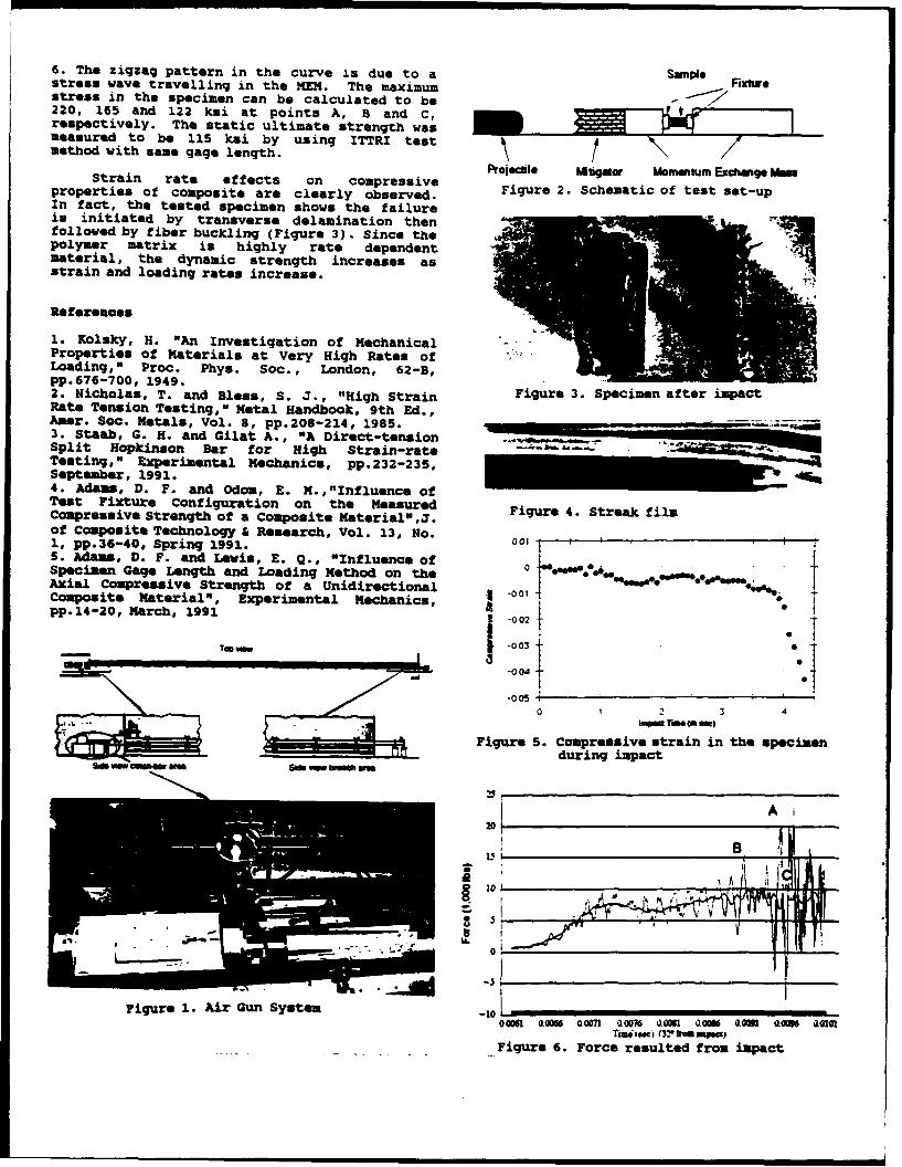
6. The zigzag pattern in the curve is due to a Samapestress wave travelling in the MEM. The maximum Ftxuwestress in the specimen can be calculated to be220, 165 and 122 ksi at points A, B and C,respectively. The static ultimate strength wasmeasured to be 115 ksi by using ITTRI testmethod with same gage length.
P•oecile ti~gor" Momentum Exchmlge i~Strain rate effects on compressive Figue 2. Semati of tes Et-up
properties of composite are clearly observed. Figure 2. Scematic of test sot-upIn fact, the tested specimen shows the failureis initiated by transverse delamination thenfollowed by fiber buckling (Figure 3). Since thepolymer matrix is highly rate dependentmaterial, the dynamic strength increases asstrain and loading rates increase.
Referenoes
1. Kolsky, H. "An Investigation of MechanicalProperties of Materials at Very High Rates ofLoading," Proc. Phys. Soc., London, 62-B,pp.676-700, 1949. " 3 "2. Nicholas, T. and Bless, S. J., "High Strain Figure 3. Specimen after impactRate Tension Testing," Metal Handbook, 9th Ed.,Amer. Soc. Metals, Vol. 8, pp.208-214, 1985.3. Staab, G. H. and Gilat A., "A Direct-temsionSplit Hopkinson Bar for High Strain-rate -Testing," Experimental Mechanics, pp.232-235,September, 1991.4. Adams, D. F. and Odom, E. M.,"Influence ofTest Fixture Configuration on the Measured Figure 4. Streak filmCompressive Strength of a Composite Material" F.of Composite Technology & Research, Vol. 13, No. 00_1, pp.36-40, Spring 1991. o015. Adams, D. F. and Lewis, E. Q. , "Influence of00o
SpecmenGag Legthand Loading Method on the".Axial Compressive Strength of a Unidirectional -001Composite Material" , Experimental Mechanics, I-0pp.14-20, March, 1991 2 -002
Too vp- .003
-V -004 +
-0 05 ,
k.w Tir (a owl
Figure 5. Compressive strain in the specimenduring impact
6 OO -mem am So" V,, WOOm emI20U.I
-
- -IAe
-3Figure 1. Air Gun System -10
00061 000 00071 00076 0061 0.00 1OO61 Q0OM Q 0101TFigureej (3!e fromp mFigure 6. Force resulted from impact
Technology Programs in Composite Structuresat the U.S. Army Missile Command
by
Terry VandiverStructures Directorate
U.S. Army Missile Command
The U.S. Army Missile Command measurement is currentlyhas a number of projects in the underway at MICOM. Opticalareas of advanced composite fibers will be incorporatedstructures. Each project has into the 3-inch pressurethe ultimate goal of improving vessels to determineweaponry for current and future practicality. The specimensmilitary systems. Most of the will then be hydroburst testedprojects described below span to determine if structuralthe FY93-95 time frame, integrity is compromised due to
One ongoing project at the optical fiber. Analysis onMICOM is 3-inch bottle testing the microstructure will beused to determine ultimate performed to determine effectsstrengths used in design of on the matrix.composite structures. The An effort is underway inmethod used for fabricating the area of service lifemandrels is tedious and time predictions. A literatureconsuming. This program will search will be performed todevelop a more efficient method obtain data on long termof fabricating bottles in exposure of composites. Aquantities consistent with series of similar testprogram needs, specimens will be fabricated
Proof testing of composite and exposed to similarstructures is currently the conditions at acceleratedmethod used at MICOM to times. The specimens will bedetermine the quality of rocket tested in the same manner asmotorcases and launch tubes. those seeing long term exposureTaguchi methods will be and a correlation between theutilized to determine the two tests will be developed.effects of the rate of The determination ofpressurization, the rate of critical fiber length in resinproof load to burst pressure, transfer molding is a programand the fiber/resin underway at MICOM. Specimenscombinations on composite test will be made and tested invessels, tensile and flexure modes. The
Incorporation of optical test specimens will be offibers into a composite simple geometry and consist ofstructure for strength, various chopped fiber lengthspressure, and temperature mixed with resin and injected
into a mold. Data from the then be impacted at differenttensile and flex tests will be levels of energy and hydroburstplotted (load vs. fiber length) to determine ultimate strength.thus determining a "critical A composites adhesivefiber length" for an program is underway thatanticipated load condition. characterizes adhesives via
Another program underway rapid heating rates. Doubleat MICOM is thermoplastic lap shear joint test specimenscoatings for use on composite will be fabricated withand metal substrates as a incorporated thermocouples nearsubstitute for CARC paint. A the adhesive joints. Testsseries of both metal and will be performed at both highcomposite substrates will be heating and loading rates toflame sprayed using selected simulate environements thatthermoplastics. The coating and adhesives encounter when usedmaterial combinations in missile systems.undergoing successful Each one of the aboveapplication will be tested for described programs is beingcoating integrity to performed jointly byenvironmental exposure, Government, universities andadhesion and flexibility. ASTM industry to encompass all thetests will be used. areas of expertise to assist in
A high use temperature solving problems encountered incomposite structures program is the completion of the tasks.underway at MICOM. Polyimideresins and phenolic triazineare the primary candidates thathave been manufactured to date.The MICOM Advanced KineticEnergy Missile System compositebooster motorcase andcenterbody sections have beenmanufactured by fourcontractors and are currentlybeing tested for bending andultimate strength at MICOM.
A technology effort isunderway at MICOM on low impactdamage of graphite/epoxycomposite structures. Taguchimethods are being utilized todetermine design enhancementswhich can be used to mitigateimpact damage and increase thesurvivability of a variety ofcomposite structures such asmotorcases and launch tubes.Additional layers, eitherfilament wound or braided willbe added to a baselinestructure. The structures will
DAMAGE MECHANISMS IN METAL MATRIX COMPOSITE PLATES
George Z. Voyiadjis, Anthony R. Venson and Peter I. KattanDepartment of Civil Engineering
Louisiana State UniversityBaton Rouge, LA 70803
ABSTRACT
Damage mechanics is used to However, in all cases, the brittle fibersinvestigate the various damage are assumed .o be elastic.mechanisms in loaded metal matrixcomposite plates. These structural The measured crack densities arecomponents are widely used in the normalized with respect to the crackArmy's vehicles and installations. They densities at the failure load. The resultsare constantly subjected to different are shown in terms of stress-straintypes of loads which give rise to the curves for the damaged components. Ininitiation and growth of various damage addition, damage curves are shownmechanisms. These mechanisms range representing plots of the damage variablein scope from matrix-related to fiber- components versus the strain. Certainrelated. In addition, certain damage conclusions and recommendations aremechanisms arise due to the effect of the made based on the results. In particular,interaction between the matrix and fibers. the critical state of damage is locatedIn general, these include void growth and and identified.coalescence, microcrack initiation, crackpropagation, fiber fracture, debonding Two approaches are considered in theand delamination, formulation of the damage model with
respect to the damage of the matrix andThe damage model is based on the fibers as shown in Figure 1. The first
concept of effective stress introduced by approach is termed "overall" in the senseKachanov (1958) and the recent work of that one damage variable is used toMurakami (1988) . A new damage characterize damage in both the matrixtensorial variable is introduced to model and fibers (Kattan and Voyiadjis, 1993).crack initiation and propagation. The The second approach is termed "local" indefinition of this tensor is based on the sense that two damage variables areexperimental measurements of the crack used to model the damage mechanismsdensity at mutually orthogonal cross- in the matrix and fibers; one for eachsections of the damaged component. The constituent (Voyiadjis and Kattan, 1993).damage model is coupled with existing Each approach has its own advantagesmaterial model to formulate an integrated and disadvantages. In the first approach,damage characterization constitutive utilizing one damage variable has themodel for metal matrix composite plates. benefit of capturing all damage effects inThe resulting coupled material model is the system. However, this approach lackcapable of analyzing both elastic and a detailed description of each damageelasto-plastic metal matrix composites. mechanism as it lumps them all into one
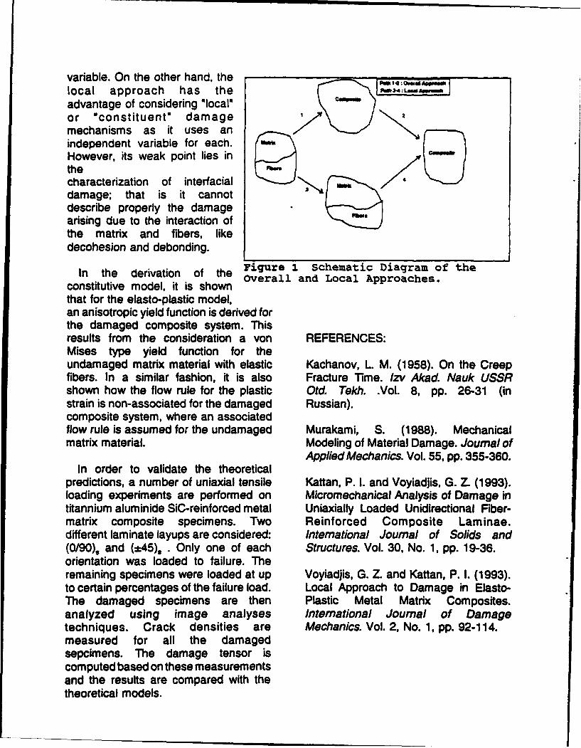
variable. On the other hand, the te•i,, ,local approach has the R03-- :Ls"Ap,,,at
advantage of considering *localoor "constituent" damage a
mechanisms as it uses anindependent variable for each.However, its weak point lies inthecharacterization of interfacialdamage; that is it cannotdescribe properly the damagearising due to the interaction ofthe matrix and fibers, likedecohesion and debonding.
In the derivation of the Figure I Schematic Diagram of theconstitutive model, it is shown Overall and Local Approaches.
that for the elasto-plastic model,an anisotropic yield function is derived forthe damaged composite system. Thisresults from the consideration a von REFERENCES:Mises type yield function for theundamaged matrix material with elastic Kachanov, L M. (1958). On the Creepfibers. In a similar fashion, it is also Fracture Time. Izv Akad. Nauk USSRshown how the flow rule for the plastic Otd. Tekh. .Vol. 8, pp. 26-31 (instrain is non-associated for the damaged Russian).composite system, where an associatedflow rule is assumed for the undamaged Murakami, S. (1988). Mechanicalmatrix material. Modeling of Material Damage. Journal of
Applied Mechanics. Vol. 55, pp. 355-360.In order to validate the theoretical
predictions, a number of uniaxial tensile Kattan, P. I. and Voyiadjis, G. Z. (1993).loading experiments are performed on Micromechanical Analysis of Damage intitannium aluminide SiC-reinforced metal Uniaxially Loaded Unidirectional Fiber-matrix composite specimens. Two Reinforced Composite Laminae.different laminate layups are considered: International Journal of Solids and(0/90), and (*45), . Only one of each Structures. Vol. 30, No. 1, pp. 19-36.orientation was loaded to failure. Theremaining specimens were loaded at up Voyiadjis, G. Z_ and Kattan, P. I. (1993).to certain percentages of the failure load. Local Approach to Damage in Elasto-The damaged specimens are then Plastic Metal Matrix Composites.analyzed using image analyses International Journal of Damagetechniques. Crack densities are Mechanics. Vol. 2, No. 1, pp. 92-114.measured for all the damagedsepcimens. The damage tensor iscomputed based on these measurementsand the results are compared with thetheoretical models.
THE EFFECT OF WIDTH ON THE FREE VIBRATION OFANISOTROPIC LAMINATED BEAMS
J. M. WhitneyProfessor of Graduate Materials Engineering
University of DaytonDayton, Ohio
ABSTRACT
Beams are well recognized as a basic structural vibration frequency. Exact solutions are obtained for theelement. Engineering studmnts ae intoduced to cassical case of specially orthotropic thin plates with twobeam theory in conjunction with sophomore strangth-of- opposite edges simply-mspported and the two adjacentmaterials which traditionally deals with homogeneous edges free. Minimum length4o-width ratios compatiblemetals. Increased use of composite materials in with e beam assumptions are establishedengineering applications has induced the need to develop for laminates having a high major Poimoa's ratio underanalytical models applicable to laminated, anisotropic bending. In order to coider angle-ply laminates withinbeams, the frmewor of pecMlly rhotpic plates, stacking
Initial development of laminated beam theory can be geometries with very week bending-twistng coupling amfound in elementary stmragth-of-mateuials where beam investigatedconstructed of different materials are considered. In this The effect of cros-sectien width is investigated bycontext laminated beams are analyzed within the considering long narrow plates with various width-to-framework of classical beam theory. In particular, each thickness ratios. In this cse it is necesasry to modifylayer is assumed to be under a state of omedim=Sio0Ql the thin plate theory to include transverse shearstress (i.e. axial normal s and transverse shear stress deforntmim in the width direction.am the only non-vanishing strmesse). For muterials withsimilar Poisson ratios, this assumption is valid. Beam Theory versus Cylindrical BendingHowever, for highly snisorpic materials with a severemismatch of Poison ratios from ply-to-ply a serious Consider a Ilminated plate having infinite length intnsverse strain inmpabil.t rmts This Mise has the y-direction with uniforn boundary conditions alongbeen initially addresed by considering bidirectional the edges (me Figure 1). If any surface or implae loadslaminates der miaxial tension loading (Dietz, 1949). ar independent of y, then the displacements and theClassical strangth-of-materials ftamewok has also been corresponding force and moment resultants areutilized for analyzing aminated, aiotropic beam. by independent of y. This theory is not compatible withVinson and Sierakowski (1986) and more recently by classical beam theory as forme and moment remltants mVasdiev (1993). induced relative to the y-direction.
Other approches to laminated beam theories haveenforced transverse strain compatibility. However,confumion exists in these oae-d nsional Mapochesbetween cylindrical bending and a beam thenry. The ydiflerance between the two models is aalogous to thediffeence between plane stress and pW e strain inclassical theory of elasticity and is clearly distinguishedby Whitney (1987). Cylindrical bending has beenconfused with beam theory. A valid laminated beamtheory Amuld reduce to classical beam theory for the cme
of a homogeneous mateial. This does not occur withcylindrica bandingWidth effects produce additional difficulties with
laminated composite beams due to the large width-to-thickness ratio of many applications, including currentflezre test specimem. In particular, laminated beams Figure 1. Cylindrical bending.are closer to a narrow plate than to a classical beam.Shear coupling produced with the inclusion of angle-plylayers in the laminate make one-dimensional A classical beam is carcteized by a p having aassmptions les valid (Kedward, 1972). high i--ckes radto with the long aides feve as
In the rre t P pqe the effect gftk o-•widt raio illuated in Figure 2. i n this mwe the force and rmon gand width-to-thickness ratio on the response of iuated istive to th io vanish. or e pan tsaisoftopic lamiated beam. is investigated. The rsultr s rethive to the ylie, etiow veri, . The iuplsaw
parameter uader consideration is the fundamental free ,iatum
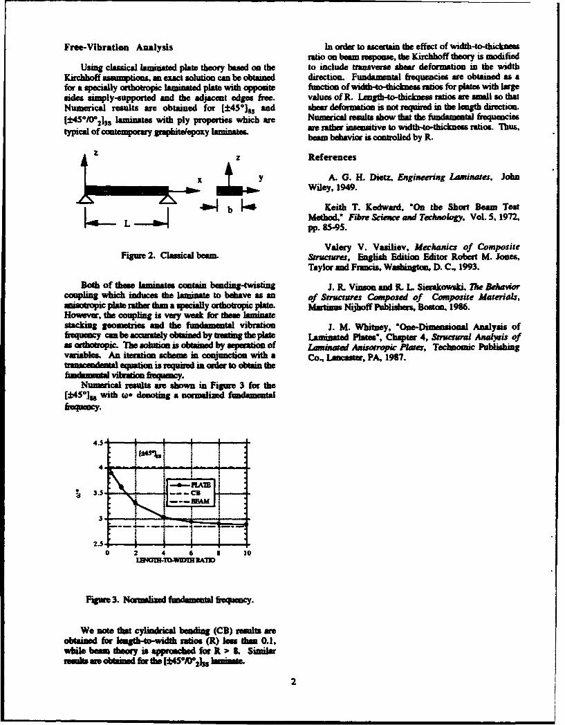
Free-V ibration Analysis In order to ascertain the effect of width-to-thicknessratio on boom response, the Kirchhoff theory is modified
Using classical laminated plate theory based on the to include transverse shear deformation in the widthKirchhoff assumptions, an exact solution can be obtained direction. Fundamenal frequenicies are obtained as afor a specially ouihotropic laminated -lt with opposite function of width-to-thickness ratios for plates with largesides simply-supported and the adjacent edges free. values of R. Lwgthi-to-thickness; ratios awe small so thatNumerical results are obtained for [±4 501. and shear defornation is not required in the length direction.[±4SIO(2l3S laminates with ply properties which ar Numeical results show that the ftxandantal frequencies
typcalof ontmpoarygnwiteepoy Inintesame rather insensitive to width-to-thickness ratios. Thus,typial o ootempsury ~ ~beam behavior is controlled by R.
z References
x yA. G. H. DieMs Engineering Laminates, John
Wiley, 1949.
Figure 2. Classical eainL Structures, English Edition Editor Robert M. Jones,Taylor and Francis, Washington, D. C., 1993.
Both of these laminates contain bending-twisting J. R. Vinson and R. L Sierakowski, The Behavorcoupling whinch induces the laminate to behave as an of Smwrucires Composed of Composise Materials,anisolropic plt rather than a specially osthotropic plate. hisstiniu Nijihoff Publishers, Boston, 1986.However, the coupling is very weak for these laminatestacking geometries and the fundamental vibration J. M. 'Whitney, "One-Dimnensional Analysis offrequency can br- acmuately obtained by treaing the plt- Lanyated Plates, Chapter 4, &tructairal Axalysis ofas orth~otpi. The solution is obtained by sepmation of Laminated Anisomrpic Plotes, Technomic Publishingvariables. An iteration schame in conjunction with a Co., Lancaster, PA, 1987.
trancndental equation is required in, order to obtain thefimdasnttlvibraton hapecy.
Numerical results wre shown in Figure 3 for the[Lt 45*], with w,. denoting a normalized fmuidamental
25 I I I.
04.56 1
4 DI-DWWNA1
2.2

linear and nonlinear viscoelastic responses isCHARACTERIZATION AND MODELING discussed. -
OF VISCOELASTIC RESPONSE The viscoelastic properties of PEEKOF PEEK RESIN AND PEEK COMPOSITE resin and APC-2 composite were
characterized by creep and creep-recoveryX.R.XIAO tests following an accelerated testing
Department of Mechanical Engineering, procedure based on the time-temperature andConcordia University superposition principle (TTSP) and time-
1455 de Maisonneuve Blvd. W., Montreal, stress superposition principle (TSSP) [1].Quebec, Canada H3G IM8 Additional information was obtained by
dynamic mechanical measurements.As compared with the pure resin,
Viscoelastic behaviour is much more APC-2 composite shows a higher dampingsignificant in polymeric materials than in over the 0' relaxation region and a lowerother types of materials. In polymer based temperature for the glass transition. Thecomposites, the viscoelastic response discrepancy is likely caused by the interphasemanifests strongly in matrix dominated layer in the composite. Thus the two-phaseproperties. Service conditions, such as micro-mechanical model may not be adequatestresses, elevated temperature and moisture to predict the viscoelastic properties.can accelerate the viscoelastic processes and The recoverable creep response, whichthus further degrade the stiffness and strength- is required for viscoelastic modeling, can beof the composite. However, the viscoelastic determined through proper mechanicalproperties are not always harmful. For models rather than mechanically conditioninginstance, the damping properties of the the specimens. PEEK resin displays bothmaterials can be utilized in controlling the instantaneous plastic deformation and time-vibration of the structures. Fiber reinforced dependeni flow. A mechanical model ispolymer composites, incorporating the high proposed to represent such a behaviour.stiffness with the high damping properties, The Schapery's nonlinear viscoelasticare excellent candidates for structures equation is mostly used in viscoelasticsubjected to dynamic loading. constitutive modeling. For the case of
The analysis and modeling of uniaxial loading it is given by [2]:viscoelastic response of composite structuresare based on the viscoelastic CorrespondencePrinciple. The viscoelastic properties of the dgcocomposite need to be determined E(t) = goSoa+ g1AS(i-j') d t' dtexperimentally and then modeled by a £ tviscoelastic constitutive equation. Theviscoelastic properties of the composite may . 1?, =..also be predicted by micromechanics V = 1(t)approaches from individual constituents. The
latter allows a broad range selection ofmaterial combination in design. (1)
The viscoelastic constitutive modelingas well as the extension of micromechanics where go, gi, g2 and a0 are the nonlinearmodels to the time domain are based on parameters with clear physical meaning [1],experimental character.-ation of real resin and AS( is the kernel function representing thecomposite systems. This paper presents linea is the relnon represetineexperimental results on the viscoelastic linear viscoelastic response, and t is time.properties of PEEK resin and PEEK The kernel function may be describedcomposite APC-2. The viscoelastic response by a modified power law containing fourof the composite is compared with that of the parameters, the so called general power law.ofuthe c osinte iconstitutive modeling for the For the creep compliance S(t), it has thepure resin. The cfollowing form:
element and modulus element can beSo-SO decoupled such that the former i s
S(t) = S�+ characterized by aT while the latter is(2) represented by parameters ao and g1g2. If
the temperature dependence of the non-linearity between the generalized external
where vo is the characteristic time parameter, force and internal force is much significantSo and Sw are the initial compliance and the than the stress dependence of the moduluscompliance at infinite time, respectively, and element, g9g2 becomes the shift factor bT.n is a material parameter. It has been shown Thus Equation 3 becomes:that the general power law can describe theviscoelastic responses over a broad time gosoa (Sos-SO/brdomain, such as fitting the master curves. e(t) = (S0-The effect of temperature can be readily b (lTaao)n
considered by the time-temperature shift t (4)
function aT and br, which are known fromthe TTSP procedure. thereby the nonlinear parameters go and a0
For the case of uniaxial loading, under can be determined from creep data only.the step stress input o[H(t)-H(t-tj)], the creep The stress-dependent viscoelastic
response predicted by the Schapery's responses of APC-2 composite wereequation with a kernel of general power law measured by 90" and 15" off-axis creep tests
for the transverse tensile mode and shearis: mode, respectively. The linear parameters in
Eq.2 were determined by a graphical TTSPSs-So procedure. While the nonlinear parameters
(1g4go-n go and ao were determined by a numericalTSSP procedure. The temperature-time shiftfactor aT follows the Arrhenius relation. The
(3) stress-time shift factor ao appears to followan exponential law, which can be traced back
As can be seen, it is impossible to determine to the energy barrier theory for thegI, g2 and ao from creep tests only. Lou and nonlinearity of viscosity. With the equationsSchapery have proposed a procedure to and parameters presented, the linear anddetermine the above parameters from creep nonlinear viscoelastic behaviours of APC-2and creep-recovery tests [2]. However, the composite laminate from ambient temperatureprocedure given in [2] implies that the creep- up to the glass transition temperature can berecovery response follows the Boltzmann described analytically.superposition principle. PEEK resin and thecomposite show severe nonlinearity in creep- Referencesrecovery response and thus the Schapery'sprocedure cannot be wed. 1. Hid, C.C., Cardon, A.H., Brinson,
It has been shown that for a H.F., 1984, NASA Contractor Reportgraphite/epoxy composite gi and g2 vary 3772.with stress level in such a way that their 2. Lou, Y.C., Schapery, R.A., J., 1971,product is nearly unity [1]. Some Composite Materials, 5: 208-234.experimental evidences suggest that aD, the 3. Xiao, X.R, Ph.D Dissertation, 1987,nonlinear parameter for the dissipation VUB, Brussels.element in Schapery's model, is stressindependent and thus can be related to thetime-temperature shift factor aT.Consequently, the stress and temperaturedependent nonlinearity of the dissipation
List of Attendees: Berdichevsky, Victor L. (Prof.)Georgia Institute of Technology
Anderson, Gary (Dr.) School of Aerospace EngineeringARO workshop monitor Atlanta, GA 30332-0150US-Army Research Office Tel: (404)-894-3000Engineering Sciences Div FAX: -2760Chief Structural Mechanics BranchPO-Box 12211 -Research Triangle Park Bogdanovich, Alexander E. (Prof.)NQ27709-2211 North Carolina State UniversityTel: (919)-549-4317 Dept of Textile Material ScienceFAX: -4310 NCSU Box 8301email: in%"anderson@aro- Raleigh, NC 27695-8301emhl.army.miL" Tel: (919)-515-6679
FAX: -6532email: in%"[email protected]"
Averill, Ronald C. (Prof.)Michigan State UniversityDept of Materials Science and Mechanics Bums, BruceA304 Engineering Building Chief Mechanics and Strucures BranchEast Lansing, Mi 48824-1226 Atn: AMSRL-WT-PDTel: (517)-355-5141 Aberdeen Proving GroundFAX: 353-9842 MD 21005-5066
Tel: (410)-278-6130/6132
Barrett, Ron (Dr.)Barrett Aerospace Technologies Cantwell, Wesley (Dr.)1500 West 9th Street, Suite 3 Polymers LaboratoryLawrence, KS 66044 Ecole Polytechnique FederaleTel and FAX: (913)-841-1293 de Lausanne
Department des MateriauxEPFL, Lausanne
Batra, Romesh C. (Prof.) Switzerland AIR MAILUniversity of Missouri-Rolla FAX: (021)-693-2935Dept of Mechanical and Aerospace entWaL dEngineering and Engrg Mechanics in dmxqmepflc
.125 Mechanical Engineering Annex h"Rolla, MO 65401-0249Tel: (314)-341-4589FAX: -4607 Carman, Greg (Prof.)
University of Californiaat Los Angeles (UCLA)
Baz, Amr (Prof.) Dept of Mechanical, AerospaceThe Catholic University of America and Nuclear EngineeringDept of Mechanical Engineering 38-137m Eng. IVWashington, DC 20064 Los Angeles, CA 90024Tel: (202)-319-5170 Tel: (310)-825-6030
FAX: -206-2302email: in%"[email protected]"
Chang, Fu-Kuo (Prof.) Dong, Stanley B. (Prof.)Stanford University University of CaliforniaDept of Aeronautics and Astronautics at Los Angeles (UCLA)Durland Building, Room 385 Deprof Civil EngineeringStanford, CA 94305-6060 3173 Engineering ITel: (415)-723-3466 Los Angeles, CA 90024-1593FAX: 725-3377 email: in%"[email protected]"emaihin%"[email protected]" Dutta, Piyush (Dr.)
US Army Cold Regions Research andEngineering Laboratory
Chattopadhyay, Aditi (Prof.) 72 Lyme RoadArizona State University Hanover, NH 03755Dept of Mechanical and Aerospace Tel: (603)-646-4212Engineering FAX: -4640Tempe, AZ85287 email: in%"pkdutt@hanover-Tel: (602)-965-3291 crreLarmy.mil"FAX: -1384emailin%"[email protected]" Fahrenthold, Eric (Prof.)
University of Texasat Austin
Chaudhuri, Reaz A. (Prof.) Dept of Mechanical EngineeringUniversity of Utah Austin, TX 78712Dept of Civil Engineering3220 Mcrrill Engineering BldgSalt Lake City, Utah 84112 Gibson, Ronald F. (Prof.)Tel: (801)-581-6931 Wayne State UniversityFAX: 585-5477 Dept of Mechanical Engineering
Detroit, MI 48202Tel: (313)-577-3702
Coulter, John (Prof.) FAX: -3881Lehigh University emaihDept of Mechanical Engineering in%"[email protected]"
and MechanicsBethlehem, PA 18015Tel: (215)-758-4503 Gramoll, Kurt (Prof.)
-4125 (Coulter) Georgia Institute of TechnologyFAX: -4041 School of Aerospace Engineeringemail: in%"[email protected]" Atlanta, GA 30332-0150
Tel: (404)-894-3065FAX: -9313Czamecki, Gregory J.
Wright LaboratoryWLFIVS Hakala, BillVehicle Sybsysterns Div National Science FoundationWright Patterson Air Force Base 1800 G Street NWOhio 45433; Washington, DC 20550
Tel: (202)-357-9542FAX: -0167
Hanagud, S. (Prof.) Jaeger, ZeevGeorgia Institute of Technology Israel Atomic Energy CommissionSchool of Aerospace Engineering Soreq Nuclear Research CenterAtlanta, GA 30332-0150 Dept. of Physics and Applied Math -
Tel: (404)-894-3040 (Hanagud) Yavne, ISRAEL 70600-2000 (main) FAX: 972-8-437361
err) =- in%"[email protected]"
Joshi, S. P. (Prof.)University of Texas at Arlington
Herrington, Paul (Prof.) Dept of Aerospace EngineeringUniversity of New Orleans PO Box 19018Dept of Mechanical Engineering Arlington, TX 76019New Orleans, LA 70148 Tel: (817)-273-3746Tel: (504)-286-6050 FAX: -794-5010FAX: -5539 email: in%"[email protected]"email: in%"pdhme)uno.edu"
Kapania, R.K. (Prof.)Hoa, Suong V. (Prof.) Virginia Polytechnic Institute
Concordia University Dept of Aerospace and OceanDept of Mechanical Engineering Engineering1455 de Maisonneuve Blvd. West Blacksburg, VA 24061Montreal, Quebec H3G-1M8CANADATel: (514)-848-3131 Kelly, JamesFAX: -3175 Advanced Research Projects Agencyemail (ARPA)in%"[email protected]" Undersea Warfare Office
3701 North Fairfax DriveArlington, VA 22203-1714
Horgan, Cornelius 0. (Prof.) Tel: (703)-696-2331University of Virginia FAX:' -2204Dept of Applied Mathematics email: in%"[email protected]"School of Engineering and
Applied ScienceCharlottesville, VA 22903-2442 Khorrami, Farshad (Prof.)Tel: (804)-924-7230 Polytechnic UniversityFAX: -6270 Dept of Electrical Engineeringemail: in%"coh8p@virgWabitnet" Five Metrotech Center
Brooklyn, NY 11201Tel: (718)-260-3227
Hui. David (Prof.) FAX: -3906ARO workshop chairman -3136University of New Orleans email: in%"[email protected]"Dept of Mecanical EngeeringNew Orleans, LA 70148Tel: (504)-286-6652 Lee, james (Prof.)FAX: -5539 George Washington Universityemail: in%"[email protected]" Dept of Mechanical Engineering
School of Engineering and Applied SciWashington, DC 20052Tel: (202)-994-6749FAX: -0238
Mayer, Arnold (Dr.) Shahkinpoor, MohsenWright Laboratory University of MexicoWLiFIV Dept of Mechanical EngineeringWright Patterson Albuquerque, NM 87131-1361 _
Air Force Base, OH 45433 Tel: (505)-277-3966email: in%"mayerah.wLfiv@fivmailgw" FAX -1571
email: in%"[email protected]"
Measures, Ray (Prof.)University of Toronto Sigur, WandaInstitute for Aerospace Studies Martin Marietta Space System4925 Dufferin Street Section Chief Composites TechnologyDownsview, Ontario PO Box 29304, mail stop 4345Canada M3H-5T6 13000 Old Gentilly Road
New Orleans, LA 70189Tel: (504)-257-2133 (Sigur)
Nayfeh, Adnan H. (Prof.) -3311 (main)University of Cincinnati FAX: -4406Dept of Aerospace Engineering
and Engineering MechanicsCincinnati, OH 45221 Simitses, George (Prof.)Tel: (513)-556-3548 University of CincinnatiFAX: -5038 Dept of Aerospace Engineering
and Engineering Mechanics797 Rhodes Hall (#70)
Pang, Su-Seng (Prof.) Cincinnati, OH 45221Louisiana State University Tel: (513)-556-3548Dept of Mechanical Engineering FAX: -5038Baton Rouge, LATel: (504)-388-5792FAX: -5990 Spicola, Frank
Naval Undersea Warfare CenterCode 8215, Bldg 679
Rajapakse, Yapa D.S. (Dr.) Structures Technology BranchOffice of Naval Research Newport LaboratoryMechanics Division Newport, RI 02841-5047Code 1132-SM Tel: (401)-841-2553800 North Quincy St. FAX: -1144Arlington, VA 22217-5000Tel: (703)-696-4405FAX: -0934 Tessler, Alexander (Dr.)entail NASA Langley Research Centerin% "onnnch@ccff'Lnavy~miL" Computational Mechanics Branch
mail stop 240Hampton, VA 23681-0001
Rao, Vitta (Prof.) Tel: (804)-864-3178University of Missouri-Rolla emaiL:Dept of Elecuocal Engineering in%"[email protected] .nasa.gov"Inolligent Systems CenterRolla, Mo 65401-0249Tel: (314)-341-6371FAX: -6512"email: in%"[email protected]"
Tzeng, Jerome T. (Dr.) Xiao, X.R. (Prof.)US Army Research Laboratory Concordia UniversityWeapon Technologies Directorate Dept of Mechanical EngineeringAMSRL-WT-PD Montreal, Quebec H3G-1M8Aberdeen Proving Ground; CANADAMD 21005-5066 Tel: (514)-848-3131Tel: (410)-278-6121 -3166 (Xiao)email: in%"[email protected]" FAX: -3175
emaihinA'[email protected]"
Vandiver, TerryUS Army Missile CommandMail Code AMSMI-RD-ST-CNRedstone ArsenalAL 35898Tel: (205)-876-1015FAX: -842-9800
Voyiadjis, George Z. (Prof.)Louisianaz State UniversityDept of Civil EngineeringBaton Rouge, LA 70803Tel: (504)-388-8668FAX: -5990
Weiss, Marc S. (Dr.)Chief ScientistNaval Biodynanics Laboratory13800 Old Gentilly RoadP.O. Box 29407New Orleans, LA 70189-0407Tel: (504)-257-3979
-3917 (main)FAX: -5456emnalk
- in%"[email protected]"
Whitney, James (Prof.)The University of DaytonGraduate Materials Engineering300 College ParkDayton, OH 45469-0240Tel: (513)-229-2679FAX: -3433
![UU PAPER-1 UU Roll No. AA UU...1-AA ] [ 3 ] [ P.T.O. UU UU UU UU UU UU UU UU UU UU UU UU UU 003. The trajectory of a projectile in a vertical plane is y x x=a b-2 where a band are](https://img.pdfslide.us/doc/110x75/5f67099c83705d66d477d4c0/uu-paper-1-uu-roll-no-aa-uu-1-aa-3-pto-uu-uu-uu-uu-uu-uu-uu-uu-uu.jpg)


![UU PAPER-2 PCB Roll No. BA · 2-BA ] [ 3 ] [ P.T.O. UU UU UU UU UU UU UU UU UU UU UU UU UU 002. Two children Ramesh (on path ARB) and Sohan (on path ASB), travel down slides of identical](https://img.pdfslide.us/doc/110x75/5e1483c6a3dd674c594e381f/uu-paper-2-pcb-roll-no-ba-2-ba-3-pto-uu-uu-uu-uu-uu-uu-uu-uu-uu-uu-uu.jpg)