Embed Size (px)
Citation preview

M SERIES SHELTER
OPERATION & MAINTENANCE MANUALWARNING: Failure to follow the operating procedures described in this manual may result in damage
to the equipment and are not covered under warranty. Please read before proceeding.
This manual contains privileged and confidential information. Any copying, disclosure, dissemination, ordistribution of this manual or its contents is strictly forbidden without the written consent from DHS SYSTEMSLLC. Additional copies of this manual are available from DHS SYSTEMS LLC.
33 Kings Highway, Orangeburg, NY 10962 Phone: 845-359-6066 Fax: 845-365-2114
Hotline: 800-977-3647DHS MANUAL NUMBER: 95330-00 Web: www.drash.comIssued – July 24, 2004 email: [email protected]
ISO 9001: 2000 RegisteredQuality Management System
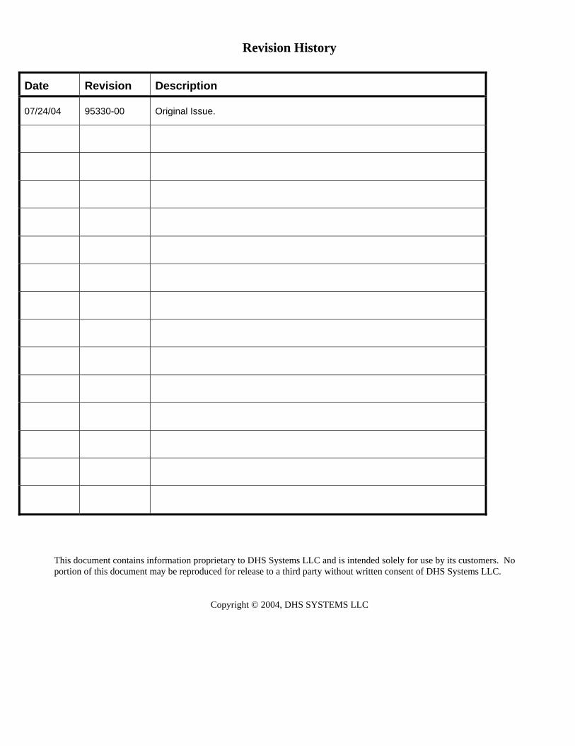
Revision History
Date Revision Description
07/24/04 95330-00 Original Issue.
This document contains information proprietary to DHS Systems LLC and is intended solely for use by its customers. Noportion of this document may be reproduced for release to a third party without written consent of DHS Systems LLC.
Copyright © 2004, DHS SYSTEMS LLC
WARNING SUMMARYThis Warning Summary explains the use of general safety Note, Caution, and Warning notices present in this TechnicalManual that must be understood and applied during the operation and maintenance of this equipment. Failure to observethese precautions could result in serious injury or death to personnel.
Equipment Specific Safety IssuesGeneralThe cautions and warnings point out known conditions that are potentially hazardous. However, no manual can cover everypossible situation. If in doubt, contact DHS.
Service and repair procedures not covered in this manual should be performed only by authorized DHS technicians.
General PrecautionsREMEMBER SAFETY FIRST. If unsure of the instructions or proper operating procedures, contact DHS beforecontinuing.
This manual emphasizes the safety precautions necessaryduring the operation and maintenance of the M SeriesShelter. Each section uses caution and warning messagesfor both the safety of the operator as well as the durabilityof the equipment. If any of the cautions or warnings is notreadily understood, contact DHS before proceeding.
When an abnormal condition is observed and procedures inthe manual do not specifically describe the condition, alloperations should be stopped and DHS Systems should beimmediately contacted for assistance.
Qualified PersonnelA qualified person is one who is familiar with this manual, the operation of the M Series Shelter and the hazards involved inits operation and maintenance and who has been certified by the DHS SYSTEMS LLC Training program.
This manual is not intended to be a substitute for proper training. DHS SYSTEMS LLC strongly recommends thatoperators receive training directly from DHS SYSTEMS LLC.
DHS SYSTEMS LLC Contact InformationPhone: 800-977-3647
FAX: 845-365-2114 e-mail: [email protected]
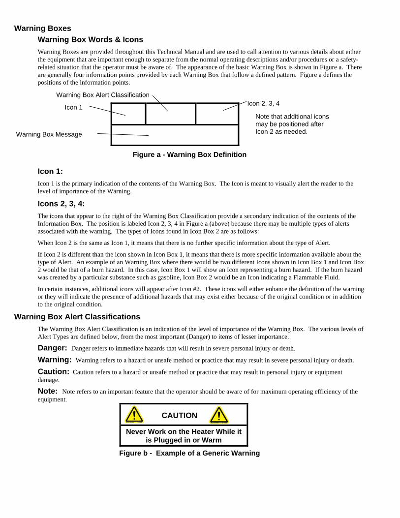
Warning BoxesWarning Box Words & IconsWarning Boxes are provided throughout this Technical Manual and are used to call attention to various details about eitherthe equipment that are important enough to separate from the normal operating descriptions and/or procedures or a safety-related situation that the operator must be aware of. The appearance of the basic Warning Box is shown in Figure a. Thereare generally four information points provided by each Warning Box that follow a defined pattern. Figure a defines thepositions of the information points.
Figure a - Warning Box Definition
Icon 1:Icon 1 is the primary indication of the contents of the Warning Box. The Icon is meant to visually alert the reader to thelevel of importance of the Warning.
Icons 2, 3, 4:The icons that appear to the right of the Warning Box Classification provide a secondary indication of the contents of theInformation Box. The position is labeled Icon 2, 3, 4 in Figure a (above) because there may be multiple types of alertsassociated with the warning. The types of Icons found in Icon Box 2 are as follows:
When Icon 2 is the same as Icon 1, it means that there is no further specific information about the type of Alert.
If Icon 2 is different than the icon shown in Icon Box 1, it means that there is more specific information available about thetype of Alert. An example of an Warning Box where there would be two different Icons shown in Icon Box 1 and Icon Box2 would be that of a burn hazard. In this case, Icon Box 1 will show an Icon representing a burn hazard. If the burn hazardwas created by a particular substance such as gasoline, Icon Box 2 would be an Icon indicating a Flammable Fluid.
In certain instances, additional icons will appear after Icon #2. These icons will either enhance the definition of the warningor they will indicate the presence of additional hazards that may exist either because of the original condition or in additionto the original condition.
Warning Box Alert ClassificationsThe Warning Box Alert Classification is an indication of the level of importance of the Warning Box. The various levels ofAlert Types are defined below, from the most important (Danger) to items of lesser importance.
Danger: Danger refers to immediate hazards that will result in severe personal injury or death.
Warning: Warning refers to a hazard or unsafe method or practice that may result in severe personal injury or death.
Caution: Caution refers to a hazard or unsafe method or practice that may result in personal injury or equipmentdamage.
Note: Note refers to an important feature that the operator should be aware of for maximum operating efficiency of theequipment.
CAUTION
Never Work on the Heater While itis Plugged in or Warm
Figure b - Example of a Generic Warning
Icon 1 Icon 2, 3, 4Warning Box Alert Classification
Warning Box Message
Note that additional iconsmay be positioned afterIcon 2 as needed.
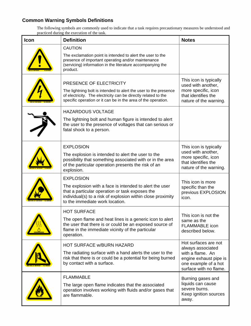
Common Warning Symbols DefinitionsThe following symbols are commonly used to indicate that a task requires precautionary measures be understood andpracticed during the execution of the task.
Icon Definition NotesCAUTION
The exclamation point is intended to alert the user to thepresence of important operating and/or maintenance(servicing) information in the literature accompanying theproduct.
PRESENCE OF ELECTRICITYThe lightning bolt is intended to alert the user to the presenceof electricity. The electricity can be directly related to thespecific operation or it can be in the area of the operation.
This icon is typicallyused with another,more specific, iconthat identifies thenature of the warning.
HAZARDOUS VOLTAGE
The lightning bolt and human figure is intended to alertthe user to the presence of voltages that can serious orfatal shock to a person.
EXPLOSION
The explosion is intended to alert the user to thepossibility that something associated with or in the areaof the particular operation presents the risk of anexplosion.
This icon is typicallyused with another,more specific, iconthat identifies thenature of the warning.
EXPLOSION
The explosion with a face is intended to alert the userthat a particular operation or task exposes theindividual(s) to a risk of explosion within close proximityto the immediate work location.
This icon is morespecific than theprevious EXPLOSIONicon.
HOT SURFACE
The open flame and heat lines is a generic icon to alertthe user that there is or could be an exposed source offlame in the immediate vicinity of the particularoperation.
This icon is not thesame as theFLAMMABLE icondescribed below.
HOT SURFACE w/BURN HAZARD
The radiating surface with a hand alerts the user to therisk that there is or could be a potential for being burnedby contact with a surface.
Hot surfaces are notalways associatedwith a flame. Anengine exhaust pipe isone example of a hotsurface with no flame.
FLAMMABLE
The large open flame indicates that the associatedoperation involves working with fluids and/or gases thatare flammable.
Burning gases andliquids can causesevere burns.Keep ignition sourcesaway.
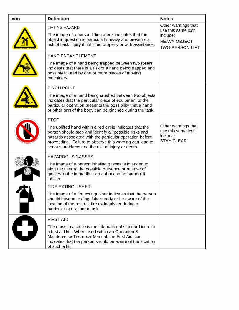
Icon Definition Notes
LIFTING HAZARD
The image of a person lifting a box indicates that theobject in question is particularly heavy and presents arisk of back injury if not lifted properly or with assistance.
Other warnings thatuse this same iconinclude:HEAVY OBJECTTWO-PERSON LIFT
HAND ENTANGLEMENT
The image of a hand being trapped between two rollersindicates that there is a risk of a hand being trapped andpossibly injured by one or more pieces of movingmachinery.
PINCH POINT
The image of a hand being crushed between two objectsindicates that the particular piece of equipment or theparticular operation presents the possibility that a handor other part of the body can be pinched during the task.
STOP
The uplifted hand within a red circle indicates that theperson should stop and identify all possible risks andhazards associated with the particular operation beforeproceeding. Failure to observe this warning can lead toserious problems and the risk of injury or death.
Other warnings thatuse this same iconinclude:STAY CLEAR
HAZARDOUS GASSES
The image of a person inhaling gasses is intended toalert the user to the possible presence or release ofgasses in the immediate area that can be harmful ifinhaled.
FIRE EXTINGUISHER
The image of a fire extinguisher indicates that the personshould have an extinguisher ready or be aware of thelocation of the nearest fire extinguisher during aparticular operation or task.
FIRST AID
The cross in a circle is the international standard icon fora first aid kit. When used within an Operation &Maintenance Technical Manual, the First Aid iconindicates that the person should be aware of the locationof such a kit.

HOW TO USE THIS MANUALWork Package DescriptionThis Technical Manual and the procedures within it are organized according to the Work Package numbering format identified inDoD Standard Practice for Preparation of Technical Information for Technical Manuals (MIL-STD-40051A) and DoD Guide to theGeneral Style Format of US Army Work Package Technical Manuals (MIL-HDBK-1222B(TM).
Work Package NumberingThe Work Package numbering and lettering sequence is derived from MIL-STD-40051, page 25, and is explained here for reference.The following alpha designators describe the specific types of information within this Technical Manual and within the specificWork Packages.
Alpha Designator Description Alpha Designator Description
G Descriptive information andtheory of operation R Repair parts and Special
Tools List (RPSTL)
I Inspection Procedures S Supporting Information
M Maintenance Procedures T Troubleshooting Procedures
O Operation Procedures
This manual uses two methods to present the Work Package numbering sequence:
The first method identifies the Parent Work Package by Alpha Designator, 5-digit Technical Manual number with revisionnumber, and Work Package Main Topic. The Work Package Main Topic identifies the general scope of the Work PackageProcedures to follow. An example Parent Work Package number is defined below.
WP O - - -.- - -95330-00 Main Procedural Topic
Work Package
Alpha Designator
WP sequence Number Place Holder
5-digit TM Number with 2-digit Rev #
Work Package Main TopicThe second numbering method identifies the titles of specific procedures by Work Package Sequence Number and WorkPackage Procedure. The Work Package Procedure Sequence Numbers will always flow from a lower number to a highernumber, indicating the progress towards completing the Main Topic Procedure. An example of a specific Work PackageProcedure is defined below.
008.00 Secure the Shelter
5-digit Work Package Procedure Sequence Number
Work Package ProcedureNote that the first three digits of the Work Package Sequence Number will never change for the life of the product.The last two digits of the Work Package Sequence Number and the last two digits of the Technical Manual Number are revisionnumbers and will change from time to time as revisions to either the product or the Work Package occur.In all instances, the last two digits of the Work Package Sequence Number and the last two digits of the Technical ManualNumber must always match. An examination of the Table of Contents page will show how the two numbering systems integrate.All Work Packages will end with “ END OF WORK PACKAGE ” statement in bold type. The next Work Package will then beginand be identified by a Parent Work Package title described above.

THIS PAGE INTENTIONALLY BLANK

M Series Shelter Operation & Maintenance
95330-00 9 DHS Systems, LLCThis document contains information proprietary to DHS Systems LLC and is intended solely for use by its customers. No portion of this document maybe reproduced for release to a third party without written consent from DHS Systems LLC.
TABLE OF CONTENTSQUICK START
M Series Shelter Setup Procedure ............................................................................ Inside Rear CoverM Series Shelter Strike Procedure............................................................................. Outside Rear Cover
1. INTRODUCTION ...................................................................................................................................1-11.1 M Series Shelter Features ........................................................................................ 1-21.2 M Series Shelter Components .................................................................................. 1-21.3 M Series Shelter Dimensions.................................................................................... 1-3
2. ERECTING THE SHELTER ..................................................................................................................2-1WP O --- . -- -95330-00 Deployment Procedure ........................................................... 2-1
001.00 Offloading the Shelter ................................................................................2-1002.00 Position the Shelter Parts ..........................................................................2-1003.00 Position Personnel & Locate the Exterior Lifting Hubs ..............................2-2004.00 Lift &Spread the Center Section ................................................................2-2005.00 Raise Center Section to Pole Height .........................................................2-3006.00 Final Push To Full Height ..........................................................................2-3007.00 Repositioning the Center Section ..............................................................2-4008.00 Erecting the End Sections .........................................................................2-4009.00 Connect End Sections to Center Sections.................................................2-5010.00 Install and Secure the Shelter Floor ..........................................................2-5011.00 Secure the Entire Shelter...........................................................................2-5END OF WORK PACKAGE .....................................................................................2-5
WP O --- . -- -95330-00 Installing Shelter Accessories ................................................. 2-6012.00 Vehicle Door Boot......................................................................................2-6013.00 Plenum.......................................................................................................2-7014.00 Window Set................................................................................................2-7015.00 “T” to “T” Connection .................................................................................2-7END OF WORK PACKAGE .....................................................................................2-7
3. STRIKING THE SHELTER....................................................................................................................3-1WP O --- . -- -95330-00 Striking Procedure .................................................................. 3-1
016.00 Prepare the Shelter....................................................................................3-1017.00 Separate the End and Center Sections .....................................................3-1018.00 Securing the End Section ..........................................................................3-1019.00 Secure the Floor & Ground Cover .............................................................3-2END OF WORK PACKAGE .....................................................................................3-2
4. FIELD MAINTENANCE OF THE SHELTER .........................................................................................4-1WP M --- . -- -95330-00 Shelter Repairs ....................................................................... 4-1
020.00 Repair of Shelter Struts .............................................................................4-1021.00 Replacement of Shelter Strut Pairs ...........................................................4-2022.00 Repair of Shelter Liner...............................................................................4-4023.00 Shelter Maintenance During Inclement Weather .......................................4-4024.00 Cleaning the Shelter & Accessories ..........................................................4-4END OF WORK PACKAGE .....................................................................................4-4
M Series Shelter Operation & Maintenance
95330-00 10 DHS Systems, LLCThis document contains information proprietary to DHS Systems LLC and is intended solely for use by its customers. No portion of this document maybe reproduced for release to a third party without written consent from DHS Systems LLC.
5. PARTS LISTS ....................................................................................................................................... 5-1WP R --- . -- -95330-00 Parts Lists............................................................................... 5-1
025.00 M Shelter Package Part Numbers............................................................. 5-1END OF WORK PACKAGE..................................................................................... 5-1
6. WARRANTY.......................................................................................................................................... Error!Bookmark not defined.
6.1 M Series Shelter Warranty Registration Form.......................................................... 6-36.2 M Series Shelter Feedback Form............................................................................. 6-5

95330-00 DHS Systems, LLCThis document contains information proprietary to DHS Systems LLC and is intended solely for use by its customers. No portion of this document maybe reproduced for release to a third party without written consent from DHS Systems LLC.
Section 1
1.1 M Series Shelter Features........................................... 1-21.2 M Series Shelter Components .................................... 1-21.3 M Series Shelter Dimensions ...................................... 1-3

95330-00 DHS Systems, LLCThis document contains information proprietary to DHS Systems LLC and is intended solely for use by its customers. No portion of this document maybe reproduced for release to a third party without written consent from DHS Systems LLC.
THIS PAGE INTENTIONALLY LEFT BLANK

M Series Shelter Operation & Maintenance
95330-00 1-1 DHS Systems, LLCThis document contains information proprietary to DHS Systems LLC and is intended solely for use by its customers. No portion of this document maybe reproduced for release to a third party without written consent from DHS Systems LLC.
1. INTRODUCTION
DRASH is an acronym for DEPLOYABLE RAPID ASSEMBLY SHELTER. The shelter can be deployed by a minimumof four people in a matter of minutes. It does not require any assembly in the field and it does not require any specialequipment for either erecting or striking.
The major component of the DRASH Shelter is a frame with two (2) pre-attached covers. The Frame consists of anarrangement of various sized Titanite® struts. Struts are connected as pairs and articulate at the hubs. These hubs enablethe struts to move freely. The unique frame design allows for quick erect and strike.
Each DRASH M Series Shelter is divided into four distinct sections with two Center Sections and two End Sections. Thismodule arrangement provides the ability to add or subtract Sections to fit mission requirements as well as arrange theSections such that all doors are either on one side or opposing sides and to join with other DRASH series shelters to formlarge complexes.
The basic features of the DRASH M Series are shown in Figure 1-1.
Figure 1-1 - DRASH Shelter Basic Features

M Series Shelter Operation & Maintenance
95330-00 1-2 DHS Systems, LLCThis document contains information proprietary to DHS Systems LLC and is intended solely for use by its customers. No portion of this document maybe reproduced for release to a third party without written consent from DHS Systems LLC.
1.1 M Series Shelter FeaturesBoth the interior and exterior cover are made with specially coated polyester fabrics named XYTEX®. All fabrics are fireretardant, mildew resistant and water repellent. They have abrasion resistance and are UV resistant. The exterior fabricincludes blackout in the visual and near infrared spectrum.
The interior and exterior cover are pre-attached to the frame using “KEEPERS” at the hub points in such a way that there isapproximately one foot of dead air space between the two covers that acts as natural insulation. These covers are easilyremovable in the event of damage or change of venue.
The “GROUND COVER” and “FLOOR” are made from a heavy-duty polyester material. The ground cover provides abarrier against insects and vermin, abrasion and ground moisture. The floor acts as an inner lining. All shelters featurescreen windows, electrical ports, conditioned air supply and return duct ports, built-in screen doors, wind lines, and groundstake loops.
1.2 M Series Shelter ComponentsThe following list names the primary componentsthat comprise each of the two (2) Center Sections ofthe M Shelter.
Ref # Quantity Item
(per section)
1. 1 M Shelter Section
2. 1 Floor
3. 1 Ground Cover
4. 4 Push Poles (PVC)
5. 1 Field Repair Kit
6. 3 Cinch Belt
7. 1 Transport Bag
8. 1 O & M Manual
Figure 1-2 - Major Shelter Components

M Series Shelter Operation & Maintenance
95330-00 1-3 DHS Systems, LLCThis document contains information proprietary to DHS Systems LLC and is intended solely for use by its customers. No portion of this document maybe reproduced for release to a third party without written consent from DHS Systems LLC.
1.3 M Series Shelter DimensionsFigure 1-3 detail the various M Shelter dimensions.
Figure 1-3 - M Shelter Configuration Dimensions

M Series Shelter Operation & Maintenance
95330-00 1-4 DHS Systems, LLCThis document contains information proprietary to DHS Systems LLC and is intended solely for use by its customers. No portion of this document maybe reproduced for release to a third party without written consent from DHS Systems LLC.
THIS PAGE INTENTIONALLY LEFT BLANK

95330-00 DHS Systems, LLCThis document contains information proprietary to DHS Systems LLC and is intended solely for use by its customers. No portion of this document maybe reproduced for release to a third party without written consent from DHS Systems LLC.
Section 2
2. ERECTING THE SHELTER.......................................................... 2-1WP O --- . -- -95330-00 Deployment Procedure ................. 2-1
001.00 Offloading the Shelter ..................................... 2-1002.00 Position the Shelter Parts ............................... 2-1003.00 Position Personnel & Locate Lifting Hubs....... 2-2004.00 Lift &Spread the Center Section ..................... 2-2005.00 Raise Center Section to Pole Height .............. 2-3006.00 Final Push To Full Height ............................... 2-3007.00 Repositioning the Center Section ................... 2-4008.00 Erecting the End Sections .............................. 2-4009.00 Connect End Sections to Center Sections...... 2-5010.00 Install and Secure the Shelter Floor ............... 2-5011.00 Secure the Entire Shelter................................ 2-5END OF WORK PACKAGE ............................................. 2-5
WP O --- . -- -95330-00 Installing Shelter Accessories....... 2-6012.00 Vehicle Door Boot........................................... 2-6013.00 Plenum............................................................ 2-7014.00 Window Set..................................................... 2-7015.00 “T” to “T” Connection ...................................... 2-7END OF WORK PACKAGE ............................................. 2-7

95330-00 DHS Systems, LLCThis document contains information proprietary to DHS Systems LLC and is intended solely for use by its customers. No portion of this document maybe reproduced for release to a third party without written consent from DHS Systems LLC.
THIS PAGE INTENTIONALLY LEFT BLANK

M Series Shelter Operation & Maintenance
95330-00 2-1 DHS Systems, LLCThis document contains information proprietary to DHS Systems LLC and is intended solely for use by its customers. No portion of this document maybe reproduced for release to a third party without written consent from DHS Systems LLC.
2. ERECTING THE SHELTERThis manual and a separate video tape or CD-ROM have been prepared to assist you in understanding the correct procedurefor deploying and striking the Shelter.
WP O --- . -- -95330-00 Deployment ProcedureFOLLOW THESE PROCEDURES TO INSURE PROPER DEPLOYMENT AND STRIKING OF THE SHELTERS.
001.00 Offloading the ShelterTo off-load the Shelter package from any platform;1. Assign one member from the four people (minimum) as the
TEAM LEADER to be responsible for coordinating thesmooth and uniform motion of the deployment crew.
2. Lift and slide the shelter so that it remains parallel with theground (see Figure 2-1).
3. Do not rock the shelter when off-loading. Rocking maycause damage to the struts (see Figure 2-1).
YES YES NOFigure 2-1 - Offloading the Shelter
002.00 Position the Shelter PartsThe M Series Shelter is comprised of two (2) End Sections, two (2) Center Sections, with each Section having its own fabricTarp and Floor.1. Clear enough space to erect the Shelter.2. Open the Transport Bag and remove the Field Repair Kit, Push Poles, and the cinched Shelter Sections.3. Unwrap the Ground Cover and Floor. The Ground Cover has coated staking loops around the edge.4. Place the ground cover on site (Stenciled side up).5. Place one End Section on each end of the Ground Cover as
shown in Figure 2-2.6. Place the two Center Section on the center of the Ground
Cover as shown in Figure 2-2.a) Position the Center Sections with the exterior sides
facing up and the white sides down.b) Each of the Center Sections has one built-in side doorway.
Determine whether the installation should have both sidedoorways on one side of the M Shelter or one side doorway oneither side of the shelter and position each of the center sectionsaccordingly.NOTE that the position of the side doorway is indicated on eachCenter Section by two different colored keeper disks.
For instance, if the Center Section color is Green, most of thekeeper disks will also be Green but there will be two Tancolored circular disks to indicate the position of the doorway.
Figure 2-2 - Shelter Section Layout and Side Door Identification7. Remove the Shelter cinch straps and place them in the Transport Bag to prevent loss.
CAUTION
THIS STEP REQUIRES FOUR PERSONNELTO LIFT THE SHELTER PACKAGE FROM
THE TRANSPORT VEHICLE AND LOWER ITTO THE GROUND.
Off color keepersID side doorway
End SectionCenter Section
Center SectionEnd Section
M Series Shelter Operation & Maintenance
95330-00 2-2 DHS Systems, LLCThis document contains information proprietary to DHS Systems LLC and is intended solely for use by its customers. No portion of this document maybe reproduced for release to a third party without written consent from DHS Systems LLC.
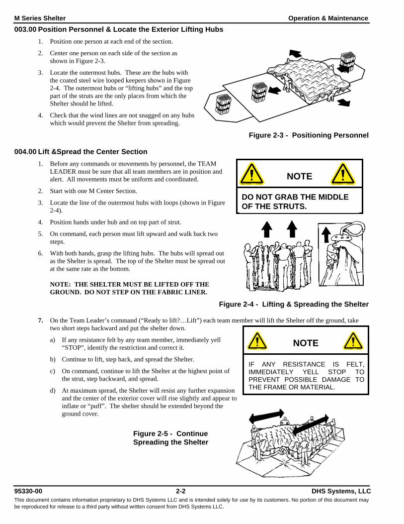
003.00 Position Personnel & Locate the Exterior Lifting Hubs1. Position one person at each end of the section.
2. Center one person on each side of the section asshown in Figure 2-3.
3. Locate the outermost hubs. These are the hubs withthe coated steel wire looped keepers shown in Figure2-4. The outermost hubs or “lifting hubs” and the toppart of the struts are the only places from which theShelter should be lifted.
4. Check that the wind lines are not snagged on any hubswhich would prevent the Shelter from spreading.
Figure 2-3 - Positioning Personnel
004.00 Lift &Spread the Center Section1. Before any commands or movements by personnel, the TEAM
LEADER must be sure that all team members are in position andalert. All movements must be uniform and coordinated.
2. Start with one M Center Section.
3. Locate the line of the outermost hubs with loops (shown in Figure2-4).
4. Position hands under hub and on top part of strut.
5. On command, each person must lift upward and walk back twosteps.
6. With both hands, grasp the lifting hubs. The hubs will spread outas the Shelter is spread. The top of the Shelter must be spread outat the same rate as the bottom.
NOTE: THE SHELTER MUST BE LIFTED OFF THEGROUND. DO NOT STEP ON THE FABRIC LINER.
Figure 2-4 - Lifting & Spreading the Shelter
7. On the Team Leader’s command (“Ready to lift?…Lift”) each team member will lift the Shelter off the ground, taketwo short steps backward and put the shelter down.
a) If any resistance felt by any team member, immediately yell“STOP”, identify the restriction and correct it.
b) Continue to lift, step back, and spread the Shelter.
c) On command, continue to lift the Shelter at the highest point ofthe strut, step backward, and spread.
d) At maximum spread, the Shelter will resist any further expansionand the center of the exterior cover will rise slightly and appear toinflate or “puff”. The shelter should be extended beyond theground cover.
Figure 2-5 - ContinueSpreading the Shelter
NOTE
DO NOT GRAB THE MIDDLEOF THE STRUTS.
NOTE
IF ANY RESISTANCE IS FELT,IMMEDIATELY YELL STOP TOPREVENT POSSIBLE DAMAGE TOTHE FRAME OR MATERIAL.
M Series Shelter Operation & Maintenance
95330-00 2-3 DHS Systems, LLCThis document contains information proprietary to DHS Systems LLC and is intended solely for use by its customers. No portion of this document maybe reproduced for release to a third party without written consent from DHS Systems LLC.
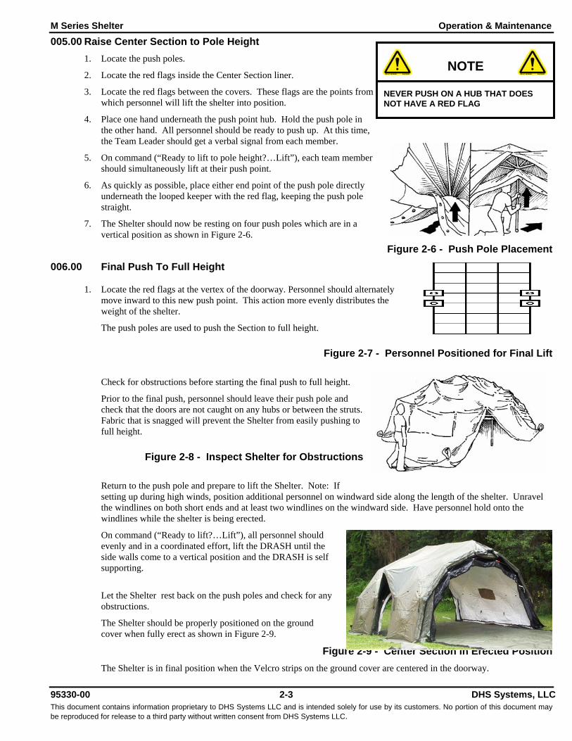
005.00 Raise Center Section to Pole Height1. Locate the push poles.
2. Locate the red flags inside the Center Section liner.
3. Locate the red flags between the covers. These flags are the points fromwhich personnel will lift the shelter into position.
4. Place one hand underneath the push point hub. Hold the push pole inthe other hand. All personnel should be ready to push up. At this time,the Team Leader should get a verbal signal from each member.
5. On command (“Ready to lift to pole height?…Lift”), each team membershould simultaneously lift at their push point.
6. As quickly as possible, place either end point of the push pole directlyunderneath the looped keeper with the red flag, keeping the push polestraight.
7. The Shelter should now be resting on four push poles which are in avertical position as shown in Figure 2-6.
Figure 2-6 - Push Pole Placement006.00 Final Push To Full Height
1. Locate the red flags at the vertex of the doorway. Personnel should alternatelymove inward to this new push point. This action more evenly distributes theweight of the shelter.
The push poles are used to push the Section to full height.
Figure 2-7 - Personnel Positioned for Final Lift
Check for obstructions before starting the final push to full height.
Prior to the final push, personnel should leave their push pole andcheck that the doors are not caught on any hubs or between the struts.Fabric that is snagged will prevent the Shelter from easily pushing tofull height.
Figure 2-8 - Inspect Shelter for Obstructions
Return to the push pole and prepare to lift the Shelter. Note: Ifsetting up during high winds, position additional personnel on windward side along the length of the shelter. Unravelthe windlines on both short ends and at least two windlines on the windward side. Have personnel hold onto thewindlines while the shelter is being erected.
On command (“Ready to lift?…Lift”), all personnel shouldevenly and in a coordinated effort, lift the DRASH until theside walls come to a vertical position and the DRASH is selfsupporting.
Let the Shelter rest back on the push poles and check for anyobstructions.
The Shelter should be properly positioned on the groundcover when fully erect as shown in Figure 2-9.
Figure 2-9 - Center Section in Erected PositionThe Shelter is in final position when the Velcro strips on the ground cover are centered in the doorway.
NOTE
NEVER PUSH ON A HUB THAT DOESNOT HAVE A RED FLAG
M Series Shelter Operation & Maintenance
95330-00 2-4 DHS Systems, LLCThis document contains information proprietary to DHS Systems LLC and is intended solely for use by its customers. No portion of this document maybe reproduced for release to a third party without written consent from DHS Systems LLC.
007.00 Repositioning the Center Section1. The red tabs on the ground cover should be between the interior and exterior hubs of the Center Section. If not, move
the Shelter so that it is positioned correctly.2. There are two methods of moving the shelter:
a) Push Poles Four people are required for this procedure.• Using the push poles, four personnel should lift at the push points identified by the red flags in each doorway
so that the Center Section is off the ground.• Move the Shelter so that it is positioned correctly.
b) Arms & HandsFor small adjustments, position personnel around the sides of the Center Section. Place one hand on the exteriorlooped keeper with a wind line and the other hand on the corresponding interior looped keeper. On command, allfour personnel should lift the wall in unison and move the Shelter into the correct position.
c) NOTE: Make sure that during this process, the end or side walls do not angle inward beyond a verticalposition. The SPOTTER should alert personnel if the walls are no longer vertical during movement of theShelter.
3. Return the Push Poles to the Transport Bag. Make sure all cinch belts and the Repair Kit are also in the bag. Stow theTransport Bag so that it is available for packing and storing.
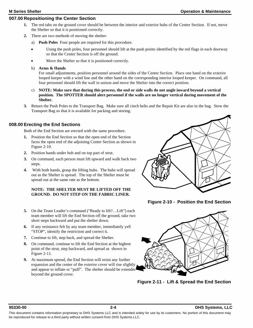
008.00 Erecting the End SectionsBoth of the End Section are erected with the same procedure.1. Position the End Section so that the open end of the Section
faces the open end of the adjoining Center Section as shown inFigure 2-10.
2. Position hands under hub and on top part of strut.3. On command, each person must lift upward and walk back two
steps.4. With both hands, grasp the lifting hubs. The hubs will spread
out as the Shelter is spread. The top of the Shelter must bespread out at the same rate as the bottom.
NOTE: THE SHELTER MUST BE LIFTED OFF THEGROUND. DO NOT STEP ON THE FABRIC LINER.
Figure 2-10 - Position the End Section
5. On the Team Leader’s command (“Ready to lift?…Lift”) eachteam member will lift the End Section off the ground, take twoshort steps backward and put the shelter down.
6. If any resistance felt by any team member, immediately yell“STOP”, identify the restriction and correct it.
7. Continue to lift, step back, and spread the Shelter.8. On command, continue to lift the End Section at the highest
point of the strut, step backward, and spread as shown inFigure 2-11.
9. At maximum spread, the End Section will resist any furtherexpansion and the center of the exterior cover will rise slightlyand appear to inflate or “puff”. The shelter should be extendedbeyond the ground cover.
Figure 2-11 - Lift & Spread the End Section

M Series Shelter Operation & Maintenance
95330-00 2-5 DHS Systems, LLCThis document contains information proprietary to DHS Systems LLC and is intended solely for use by its customers. No portion of this document maybe reproduced for release to a third party without written consent from DHS Systems LLC.
009.00 Connect End Sections to Center Sections1. Locate the red tabs affixed to the peaks of both the Center Section and
the associated End Section.2. The End Section may have to be adjusted to make a proper connection to the Center Section. If so, use personnel to lift
the End Section slightly and move back (or forward) as needed.3. Starting at the two Red tabs at the peak of each Section, begin joining
the exterior Velcro cover strips.4. Continue joining the exterior Velcro cover strips, working from the
top of the seam towards the ground.5. Complete the outside seam first, then repeat the procedure to join the
interior Velcro cover seam.6. Repeat steps 1 through 5 to connect the opposite End Section to the
Center Section.
010.00 Install and Secure the Shelter Floor1. Position the fabric floor section inside the M Shelter and secure to the edge of the floor.2. Begin securing the Velcro strip on the Floor to the exterior cover starting at the center of the respective Section.3. Open the shorter connector strip.4. Locate the longer connector strip on the other Shelter and secure the Velcro.5. Check that each connection has been properly made.
011.00 Secure the Entire Shelter1. All wind lines and staking loops must be utilized, especially during inclement and changing weather conditions. This
will help stabilize the shelter.2. Fully unravel all wind lines and stake them down 4-5 feet from shelter.3. Use the tensioner on the wind lines to keep them taut.4. Place stakes in all the stake loops around the Shelter base perimeter to insure that the shelter is adequately secured.5. During adverse weather conditions, the wind lines and stakes should be periodically checked to see that they are
properly secured.
Figure 2-12 - Shelter Staking and Tie-down Diagram
END OF WORK PACKAGE
NOTE
A LADDER OR SIMILAR DEVICE TOGAIN HEIGHT FOR PERSONNEL ISREQUIRED TO COMPLETE THISPROCEDURE.

M Series Shelter Operation & Maintenance
95330-00 2-6 DHS Systems, LLCThis document contains information proprietary to DHS Systems LLC and is intended solely for use by its customers. No portion of this document maybe reproduced for release to a third party without written consent from DHS Systems LLC.
WP O --- . -- -95330-00 Installing Shelter Accessories012.00 Vehicle Door Boot
The Shelter’s Door Boot is designed for use with specific vehicles to provide a weather and light tight seal between theshelter and vehicle. A door boot must be attached prior to final erection of shelter.
To attach the door boot:
1. Spread the Shelter.
2. Identify the door boot which will be installed over one of the doorways.
3. Locate the Brown tab on the door boot.Locate the Brown tab under the connector strip on the door.To attach the door boot to the connector strip, start at the red tab and work down on each side to the grommet locationson the door boot.
The Shelter can now be erected.a) Use caution in the doorway where the Shelter door boot is now attached.b) One person should hold the boot while the Shelter is being erected.
4. Continue with the regular Shelter deployment procedures.5. Finish attaching the Door Boot to the connector strip starting at the grommet location once the Shelter has been erected.6. Stake down the outside bottom corners of the Door Boot Floor using Stake Loops.
7. Use Velcro strips to attach the Door Boot Floor between the Ground Cover and the Shelter.8. Back the vehicle square into the center of the doorway and place the elastic part of the Boot over the vehicle.
9. Reposition the vehicle for a better fit if necessary.Figure 2-13 - Vehicle Booted to an M Shelter
DRASH M SERIES
NOTE: DRASH DOOR BOOTS ATTACH TO 1XB T M
TOP VIEW
M Series Shelter Operation & Maintenance
95330-00 2-7 DHS Systems, LLCThis document contains information proprietary to DHS Systems LLC and is intended solely for use by its customers. No portion of this document maybe reproduced for release to a third party without written consent from DHS Systems LLC.
013.00 PlenumA Plenum provides even distribution of heated or cooled air throughout the Shelter. To install the Plenum:1. Remove the Plenum from the bag.2. Insure that at least two feet (2’) of the supply ducting is pulled inside the Shelter through the duct port located above the
window near the doorway.3. Slip the Plenum over the duct until the first hook on the Plenum reaches the looped keeper closest to the duct port.4. Secure the Plenum to the duct with the provided cord.5. Attach the hooks affixed along the length of the Plenum to the corresponding looped keepers.6. The air flow through the Plenum may be regulated by adjusting the opening(s) with the drawstring.
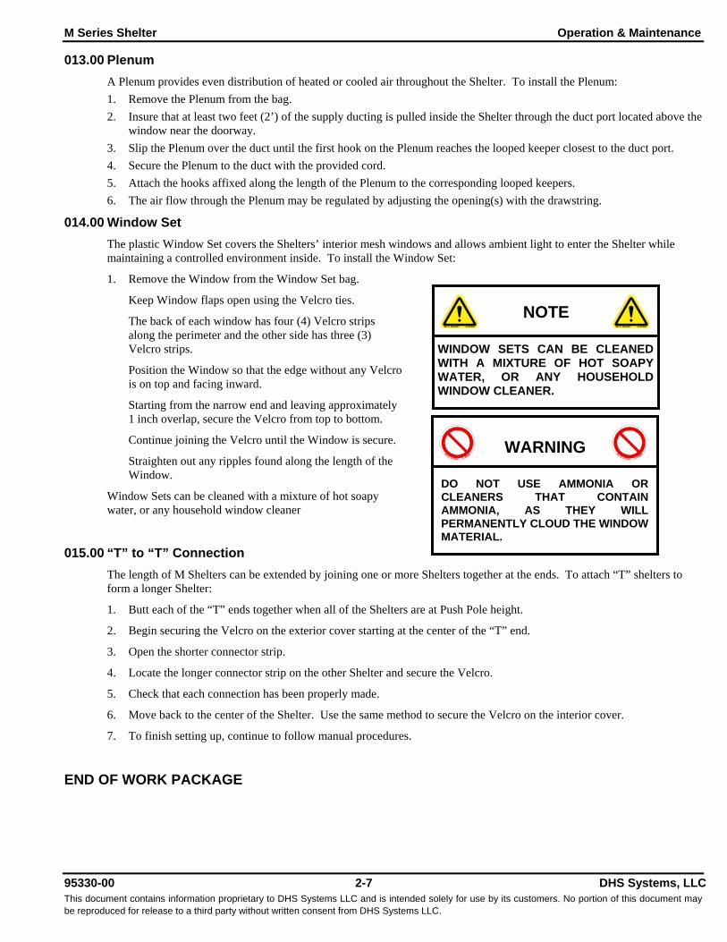
014.00 Window SetThe plastic Window Set covers the Shelters’ interior mesh windows and allows ambient light to enter the Shelter whilemaintaining a controlled environment inside. To install the Window Set:
1. Remove the Window from the Window Set bag.
Keep Window flaps open using the Velcro ties.
The back of each window has four (4) Velcro stripsalong the perimeter and the other side has three (3)Velcro strips.
Position the Window so that the edge without any Velcrois on top and facing inward.
Starting from the narrow end and leaving approximately1 inch overlap, secure the Velcro from top to bottom.
Continue joining the Velcro until the Window is secure.
Straighten out any ripples found along the length of theWindow.
Window Sets can be cleaned with a mixture of hot soapywater, or any household window cleaner
015.00 “T” to “T” ConnectionThe length of M Shelters can be extended by joining one or more Shelters together at the ends. To attach “T” shelters toform a longer Shelter:
1. Butt each of the “T” ends together when all of the Shelters are at Push Pole height.
2. Begin securing the Velcro on the exterior cover starting at the center of the “T” end.
3. Open the shorter connector strip.
4. Locate the longer connector strip on the other Shelter and secure the Velcro.
5. Check that each connection has been properly made.
6. Move back to the center of the Shelter. Use the same method to secure the Velcro on the interior cover.
7. To finish setting up, continue to follow manual procedures.
END OF WORK PACKAGE
NOTE
WINDOW SETS CAN BE CLEANEDWITH A MIXTURE OF HOT SOAPYWATER, OR ANY HOUSEHOLDWINDOW CLEANER.
WARNING
DO NOT USE AMMONIA ORCLEANERS THAT CONTAINAMMONIA, AS THEY WILLPERMANENTLY CLOUD THE WINDOWMATERIAL.

THIS PAGE INTENTIONALLY LEFT BLANK

95330-00 DHS Systems, LLCThis document contains information proprietary to DHS Systems LLC and is intended solely for use by its customers. No portion of this document maybe reproduced for release to a third party without written consent from DHS Systems LLC.
Section 3
3. STRIKING THE SHELTER .......................................................................3-1WP O --- . -- -95330-00 Striking Procedure ...........................3-1
016.00 Prepare the Shelter......................................... 3-1017.00 Separate the End and Center Sections .......... 3-1018.00 Securing the End Section ............................... 3-1019.00 Secure the Floor & Ground Cover .................. 3-2END OF WORK PACKAGE ............................................. 3-2

95330-00 DHS Systems, LLCThis document contains information proprietary to DHS Systems LLC and is intended solely for use by its customers. No portion of this document maybe reproduced for release to a third party without written consent from DHS Systems LLC.
THIS PAGE INTENTIONALLY LEFT BLANK

M Series Shelter Operation & Maintenance
95330-00 3-1 DHS Systems, LLCThis document contains information proprietary to DHS Systems LLC and is intended solely for use by its customers. No portion of this document maybe reproduced for release to a third party without written consent from DHS Systems LLC.
3. STRIKING THE SHELTERWP O --- . -- -95330-00 Striking Procedure016.00 Prepare the Shelter
1. Remove all equipment and accessories from inside the Shelter.2. Detach the floor by unfastening the Velcro.3. Remove the floor from the Shelter and fold into quarters lengthwise. Place the floor far enough away so as not to
interfere with striking the Shelter.4. Close all interior and exterior windows.5. Remove all Ground Stakes.6. Rewind the wind lines. Unwound wind lines may become tangled when the Shelter is packed.
017.00 Separate the End and Center Sections1. Starting with one End Section, separate the Velcro cover strips working from the bottom (at the floor) up to the peak of
the Section.2. Locate the Push Poles and position at least four personnel around the End Section3. On command, while maintaining visual contact, lift the End Section slightly off the ground with the Push Poles.4. Move the End Section out about six to eight inches.5. Position one person at each corner of the End Section so that they can easily grasp the exterior lifting hub.6. The team leader should circle the Shelter to verify that each person is in position and ready to execute on command.7. On command ("Ready to strike?...Strike on the count of three"), the team leader will count to three at which time each
team member must lift their hub up and out, in one swift motion. This action will release the frame wall, allowing themto compress inward.
8. On command, each team member lifts the Shelter off the ground by the hubs and walks toward the center.
Figure 3-1 - Hold Shelter by Hubs and Walk Forward
9. Before completely compressing, carefully push the exterior cover between the struts so that all keepers are exposed.10. Check that all wind lines are free and not tangled within the frame or fabric. If tangled, lift the Shelter and walk out
one to two steps, untangle and re-compress the End Section.11. Place the wind lines on top of the End Section.12. Compress further to compact the End Section.
018.00 Securing the End Section1. Invert the End Section so the white side is up.2. Spread the Shelter approximately one foot.3. Carefully push the interior liner between the struts so that all looped keepers
are exposed.4. Secure one of the cinch straps around the top section of the collapsed End
Section approximately 1.5 feet down from the top interior hubs as shown inFigure 3-2 .
Figure 3-2 - Secure First Cinch Strap
NOTE
DO NOT STEP ON THE FABRICWHICH MAY GATHER AT YOURFEET.
M Series Shelter Operation & Maintenance
95330-00 3-2 DHS Systems, LLCThis document contains information proprietary to DHS Systems LLC and is intended solely for use by its customers. No portion of this document maybe reproduced for release to a third party without written consent from DHS Systems LLC.
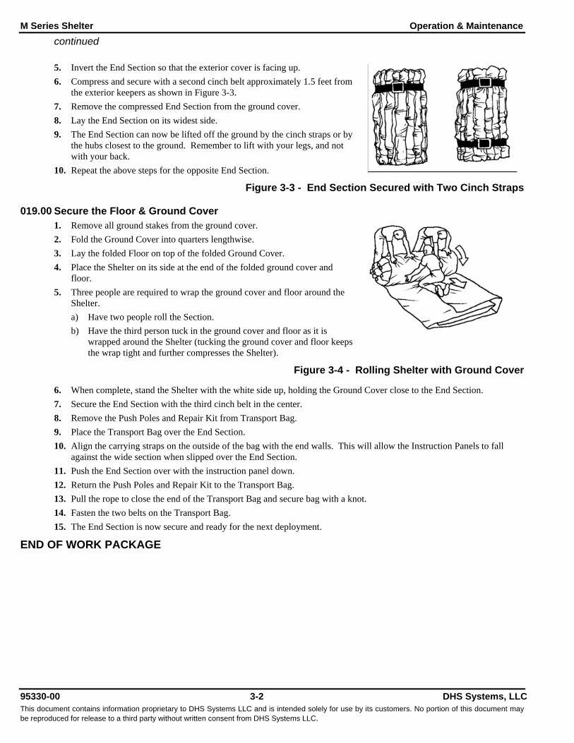
continued
5. Invert the End Section so that the exterior cover is facing up.6. Compress and secure with a second cinch belt approximately 1.5 feet from
the exterior keepers as shown in Figure 3-3.7. Remove the compressed End Section from the ground cover.8. Lay the End Section on its widest side.9. The End Section can now be lifted off the ground by the cinch straps or by
the hubs closest to the ground. Remember to lift with your legs, and notwith your back.
10. Repeat the above steps for the opposite End Section.
Figure 3-3 - End Section Secured with Two Cinch Straps
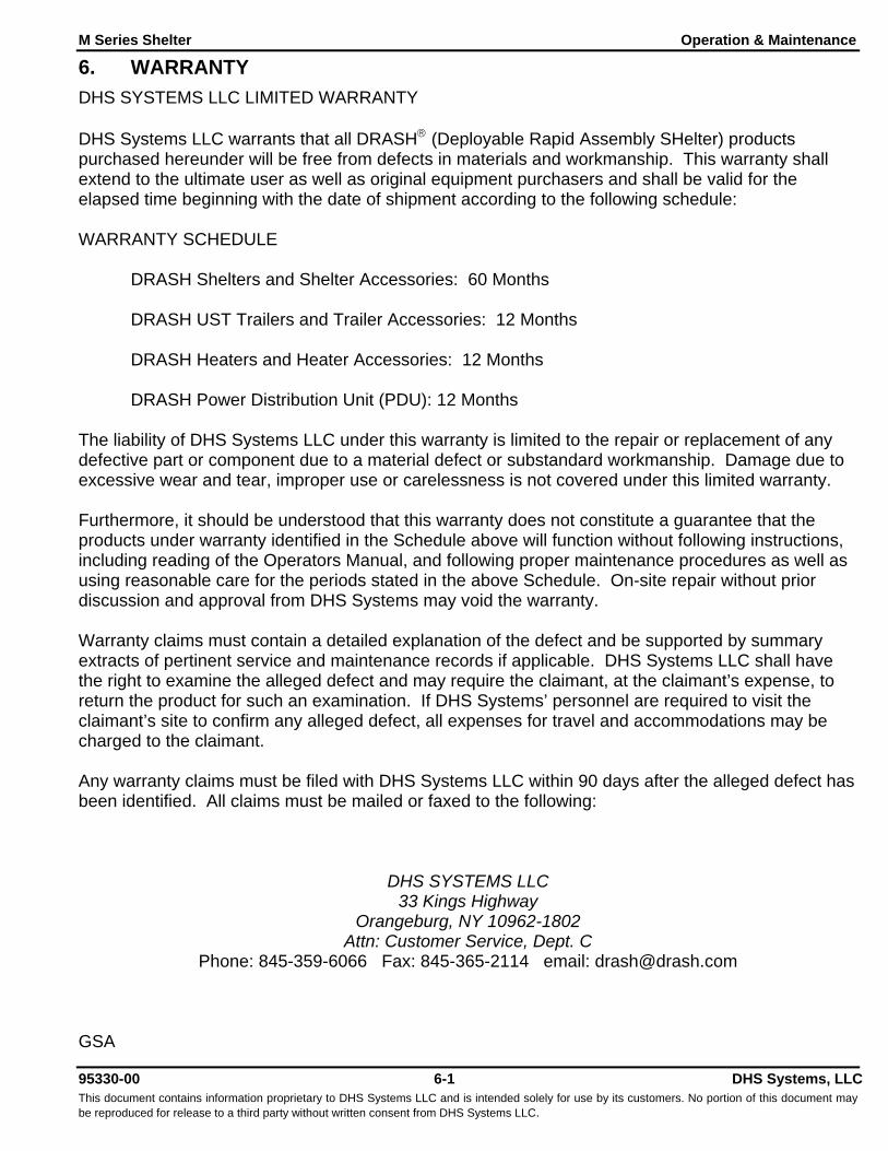
019.00 Secure the Floor & Ground Cover1. Remove all ground stakes from the ground cover.2. Fold the Ground Cover into quarters lengthwise.3. Lay the folded Floor on top of the folded Ground Cover.4. Place the Shelter on its side at the end of the folded ground cover and
floor.5. Three people are required to wrap the ground cover and floor around the
Shelter.a) Have two people roll the Section.b) Have the third person tuck in the ground cover and floor as it is
wrapped around the Shelter (tucking the ground cover and floor keepsthe wrap tight and further compresses the Shelter).
Figure 3-4 - Rolling Shelter with Ground Cover
6. When complete, stand the Shelter with the white side up, holding the Ground Cover close to the End Section.7. Secure the End Section with the third cinch belt in the center.8. Remove the Push Poles and Repair Kit from Transport Bag.9. Place the Transport Bag over the End Section.10. Align the carrying straps on the outside of the bag with the end walls. This will allow the Instruction Panels to fall
against the wide section when slipped over the End Section.11. Push the End Section over with the instruction panel down.12. Return the Push Poles and Repair Kit to the Transport Bag.13. Pull the rope to close the end of the Transport Bag and secure bag with a knot.14. Fasten the two belts on the Transport Bag.15. The End Section is now secure and ready for the next deployment.
END OF WORK PACKAGE

95330-00 DHS Systems, LLCThis document contains information proprietary to DHS Systems LLC and is intended solely for use by its customers. No portion of this document maybe reproduced for release to a third party without written consent from DHS Systems LLC.
Section 4
4. FIELD MAINTENANCE OF THE SHELTER................................4-1WP M --- . -- -95330-00 Shelter Repairs ..............................4-1020.00 Repair of Shelter Struts ............................................4-1021.00 Replacement of Shelter Strut Pairs ..........................4-2022.00 Repair of Shelter Liner..............................................4-4023.00 Shelter Maintenance During Inclement Weather......4-4024.00 Cleaning the Shelter & Accessories .........................4-4
END OF WORK PACKAGE ............................................. 4-4

95330-00 DHS Systems, LLCThis document contains information proprietary to DHS Systems LLC and is intended solely for use by its customers. No portion of this document maybe reproduced for release to a third party without written consent from DHS Systems LLC.
THIS PAGE INTENTIONALLY LEFT BLANK

M Series Shelter Operation & Maintenance
95330-00 4-1 DHS Systems, LLCThis document contains information proprietary to DHS Systems LLC and is intended solely for use by its customers. No portion of this document maybe reproduced for release to a third party without written consent from DHS Systems LLC.
4. FIELD MAINTENANCE OF THE SHELTERBefore initiating repair to any Shelter, identify the nature of the problem. Most repairs can be made with the standard FieldRepair Kit, included with the Shelter. Each kit contains the following components:Duct Tape, 1 Roll Strut Repair Sleeves, 5Spanner Wrench, 1 Exterior Looped Keeper, 1Tube Cutter, 1 Interior Looped Keeper, 21 oz Adhesive, 1 Tube Exterior Keeper, 1Wind Line, 1 Exterior Swatch Repair Fabric, 14” Scissors, 1 Interior Swatch Repair Fabric, 1
WP M --- . -- -95330-00 Shelter Repairs
020.00 Repair of Shelter StrutsFractured struts are repaired as follows:1. After identifying the fractured strut or struts, assess whether the exterior cover needs to be removed to reach the
fracture. If it is necessary to remove the exterior cover, use the spanner wrench and remove only those keepersnecessary to peel back the cover to reach the fractured strut or struts.
2. Locate the tube cutter.3. Place the strut between the cutter wheel and the rollers and bring the cutter wheel in contact with the strut by turning
the feed wheel.4. Turn the feed wheel an additional one half turn for the first cut.5. Revolve the cutter wheel around the strut slowly until the cut is complete.6. Trim off one half inch from each damaged side.7. Retrieve a repair sleeve.8. Slide a repair sleeve over the broken strut. Keep the break centered in the repair sleeve.9. Tape ONLY one end of the repair sleeve with the duct tape. This will allow the other broken end to telescope within
the sleeve and maintain its critical length (see Figure 4-1).10. Replace the liner.11. Insert the keeper and turn by hand until snug.12. Use the spanner wrench to tighten one-quarter turn past hand tight. Do not tighten excessively.13. All sewn seams should be aligned and fabric reinforced circles around keepers should not be twisted.
Figure 4-1 - Repairing Shelter Struts

M Series Shelter Operation & Maintenance
95330-00 4-2 DHS Systems, LLCThis document contains information proprietary to DHS Systems LLC and is intended solely for use by its customers. No portion of this document maybe reproduced for release to a third party without written consent from DHS Systems LLC.
021.00 Replacement of Shelter Strut PairsCONTENTS OF SPARE PARTS KIT
5 ea Interior Looped Keepers 1 ea Ratchet Screwdriver
5 ea Exterior Looped Keepers 2 ea A Side Pair/Blue
5 ea Exterior Keepers 4 ea B Side Pair/Red
2 ea Interior Hub Set 2 ea A Sub Pair/Green
2 ea Exterior Hub Set 4 ea B Sub Pair/Yellow
50 ea Screws 1 ea Spanner Wrench
If a strut pair(s) is damaged, strike the Shelter and effect repairs as follows: (refer to Figure 4-2, page 4-3.14. Identify the damaged strut pair.15. Use a spanner wrench to remove keepers from the exterior cover. Work only in the area where the damaged struts are
located (see Figure 4-2, Frame 1).16. Use the ratchet screwdriver to loosen all screws from both exterior hubs where the damaged strut pair is connected. Do
not remove damaged strut pair from hubs at this time (see Figure 4-2, Frame 2).17. Determine the color code on the damaged strut pair. The color code plug may be located on any one of the four ends of
the pair. Select the same color-coded strut pair from the spare parts kit.18. Orient the replacement strut pair so that it is identical to the damaged pair.19. Place the replacement pair next to the damaged strut pair making certain that both color coded plugs and scissor pins
match exactly (see Figure 4-2, Frame 3).20. When the replacement pair is properly positioned, remove the ends of the damaged strut pair from exterior hubs and
insert replacement strut pair (see Figure 4-2, Frame 4).21. After replacement pair is in placed, tighten the screws on the exterior hubs so that it is again secured (see Figure 4-2,
Frame 5).22. Replace the liner.23. Insert the keeper and tighten by hand until snug. Use the spanner wrench to tighten one-quarter turn past hand tight.
Do not over-tighten. All seams should be aligned and the fabric reinforced circles around the keepers should not betwisted (see Figure 4-2, Frame 6).
24. Compress and invert the Shelter.25. Repeat steps 1 and 2 on the interior liner and interior hubs.26. Remove the damaged strut pair from the hub and lift out from the frame.27. Replace the strut pair and tighten the screws on the hub so that it is again secure.28. Repeat step 9.
NOTE
REPLACING ONE OR MORE STRUTPAIRS REQUIRES THE ACQUISITIONOF A SPARE PARTS KIT CONTAININGTHE PARTS LISTED ON THE RIGHT.

M Series Shelter Operation & Maintenance
95330-00 4-3 DHS Systems, LLCThis document contains information proprietary to DHS Systems LLC and is intended solely for use by its customers. No portion of this document maybe reproduced for release to a third party without written consent from DHS Systems LLC.
Figure 4-2 - Strut Pair Replacement Frames

M Series Shelter Operation & Maintenance
95330-00 4-4 DHS Systems, LLCThis document contains information proprietary to DHS Systems LLC and is intended solely for use by its customers. No portion of this document maybe reproduced for release to a third party without written consent from DHS Systems LLC.
022.00 Repair of Shelter LinerThis repair procedure can be accomplished in any weather condition.1. Cut enough fabric to cover the tear or hole, with
approximately ¼” extra on all sides.Apply a thin layer of adhesive to the reverse side ofpatch.Apply a tin layer of adhesive to the area around the tearor hole in the Shelter to which patch will be applied.Press the patch firmly over the tear.Smooth out any air bubbles from under the patch.The patch will be secure in three hours.Allow the patch to cure for 24 hours.
023.00 Shelter Maintenance During Inclement WeatherTo prevent damage to the Shelter due to heavy snow orfreezing rain, the roof must be checked periodically for rainpuddles or ice/snow accumulation. This can be accomplishedby:
1. Shaking the exterior cover from the outside of theShelter.
Place a Push Pole between the interior and exteriorcovers and gently tapping the exterior cover until theShelter is cleared of the snow or ice accumulation.
During adverse weather conditions, routinely check and verify the security of the;a) Wind linesb) Stakesc) Keepers
024.00 Cleaning the Shelter & AccessoriesProper maintenance of the Shelter requires that it be cleaned after every field exercise. To clean the Shelter;1. Brush off all excess dirt/debris with a soft bristle brush.
Using a cloth, sponge or mop, the shelter can be manually cleaned using a mixture of warm water and mild householddetergent.Remove grease, oil, or other heavy stains by scrubbing with Simple Green® or equivalent.Rinse with clean water.Allow the Shelter to dry completely before repackaging.
END OF WORK PACKAGE
NOTE
IF TIME DOES NOT ALLOW FOR THE ABOVEPROCEDURE, THE REPAIR CAN BE DONE ONA TEMPORARY BASIS USING DUCT TAPE.
NOTE
A POWER WASHER MAY BE USED AT LOWPRESSURE WITH WARM WATER. USE GOODJUDGMENT AND CAUTION REGARDINGWATER PRESSURE AND TEMPERATURE.
WARNING
DO NOT USE SOLVENTS TO CLEAN THESHELTER.THEY WILL DISSOLVE THE PROTECTIVECOATING ON THE FABRIC.
NOTETHE SHELTER SHOULD BE STRICKEN IF IT ISTO BE LEFT UNATTENDED FOR ANEXTENDED PERIOD WHEN THERE IS APOSSIBILITY OF INCLEMENT WEATHER.

95330-00 DHS Systems, LLCThis document contains information proprietary to DHS Systems LLC and is intended solely for use by its customers. No portion of this document maybe reproduced for release to a third party without written consent from DHS Systems LLC.
Section 5
5. PARTS LISTS ...............................................................................5-1WP R --- . -- -95330-00 Parts List ........................................5-1
025.00 M Shelter Package Part Numbers .................. 5-1END OF WORK PACKAGE ............................................. 5-1

95330-00 DHS Systems, LLCThis document contains information proprietary to DHS Systems LLC and is intended solely for use by its customers. No portion of this document maybe reproduced for release to a third party without written consent from DHS Systems LLC.
THIS PAGE INTENTIONALLY LEFT BLANK

M Series Shelter Operation & Maintenance
95330-00 5-1 DHS Systems, LLCThis document contains information proprietary to DHS Systems LLC and is intended solely for use by its customers. No portion of this document maybe reproduced for release to a third party without written consent from DHS Systems LLC.
5. PARTS LISTS
WP R --- . -- -95330-00 Parts Lists
025.00 M Shelter Package Part Numbers
Item # Description Part #
1. M Shelter System, green MA100100
2. 1XBT M Section, green MA100105
3. Complete M Section MA100110
4. Cover, Exterior, green MA100120
5. Side Door, Exterior, green MA100130
6. Shelter Transport Bag, M, brown MA100140
7. Shelter Transport Bad, 1XBTM, brown MA100145
8. Ancillary Bag, brown, double handle MA100150
9. Connector Bag, Large, brown MA100155
10. Connector Bag, Small, brown MA100160
11. Tent Stake Bag, brown MA100165
12. DRASHLite Bag, brown MA100170
13. Repair Kit Bag, brown MA100175
14. Spare Parts Kit Bag, brown MA100180
15. Interior Cover MA100300
16. Interior Side Door MA100310
17. Ground Cover MA100700
18. Floor MA100710
19. Exterior Stake Bracket, M MA100720
20. Staking Bracket Screw, M MA100725
21. Operators Manual 95330-00
END OF WORK PACKAGE

THIS PAGE INTENTIONALLY LEFT BLANK

95330-00 DHS Systems, LLCThis document contains information proprietary to DHS Systems LLC and is intended solely for use by its customers. No portion of this document maybe reproduced for release to a third party without written consent from DHS Systems LLC.
Section 6
6. WARRANTY......................................................................... 6-16.1 M Series Shelter Warranty Registration Form............. 6-16.2 M Series Shelter Feedback Form................................ 6-3

95330-00 DHS Systems, LLCThis document contains information proprietary to DHS Systems LLC and is intended solely for use by its customers. No portion of this document maybe reproduced for release to a third party without written consent from DHS Systems LLC.
THIS PAGE INTENTIONALLY LEFT BLANK
M Series Shelter Operation & Maintenance
95330-00 6-1 DHS Systems, LLCThis document contains information proprietary to DHS Systems LLC and is intended solely for use by its customers. No portion of this document maybe reproduced for release to a third party without written consent from DHS Systems LLC.
6. WARRANTYDHS SYSTEMS LLC LIMITED WARRANTY
DHS Systems LLC warrants that all DRASH® (Deployable Rapid Assembly SHelter) productspurchased hereunder will be free from defects in materials and workmanship. This warranty shallextend to the ultimate user as well as original equipment purchasers and shall be valid for theelapsed time beginning with the date of shipment according to the following schedule:
WARRANTY SCHEDULE
DRASH Shelters and Shelter Accessories: 60 Months
DRASH UST Trailers and Trailer Accessories: 12 Months
DRASH Heaters and Heater Accessories: 12 Months
DRASH Power Distribution Unit (PDU): 12 Months
The liability of DHS Systems LLC under this warranty is limited to the repair or replacement of anydefective part or component due to a material defect or substandard workmanship. Damage due toexcessive wear and tear, improper use or carelessness is not covered under this limited warranty.
Furthermore, it should be understood that this warranty does not constitute a guarantee that theproducts under warranty identified in the Schedule above will function without following instructions,including reading of the Operators Manual, and following proper maintenance procedures as well asusing reasonable care for the periods stated in the above Schedule. On-site repair without priordiscussion and approval from DHS Systems may void the warranty.
Warranty claims must contain a detailed explanation of the defect and be supported by summaryextracts of pertinent service and maintenance records if applicable. DHS Systems LLC shall havethe right to examine the alleged defect and may require the claimant, at the claimant’s expense, toreturn the product for such an examination. If DHS Systems’ personnel are required to visit theclaimant’s site to confirm any alleged defect, all expenses for travel and accommodations may becharged to the claimant.
Any warranty claims must be filed with DHS Systems LLC within 90 days after the alleged defect hasbeen identified. All claims must be mailed or faxed to the following:
DHS SYSTEMS LLC33 Kings Highway
Orangeburg, NY 10962-1802Attn: Customer Service, Dept. C
Phone: 845-359-6066 Fax: 845-365-2114 email: [email protected]
GSA

M Series Shelter Operation & Maintenance
95330-00 6-2 DHS Systems, LLCThis document contains information proprietary to DHS Systems LLC and is intended solely for use by its customers. No portion of this document maybe reproduced for release to a third party without written consent from DHS Systems LLC.
THIS PAGE INTENTIONALLY LEFT BLANK

M Series Shelter Operation & Maintenance
95330-00 6-3 DHS Systems, LLCThis document contains information proprietary to DHS Systems LLC and is intended solely for use by its customers. No portion of this document maybe reproduced for release to a third party without written consent from DHS Systems LLC.
6.1 M Series Shelter Warranty Registration Form

M Series Shelter Operation & Maintenance
95330-00 6-4 DHS Systems, LLCThis document contains information proprietary to DHS Systems LLC and is intended solely for use by its customers. No portion of this document maybe reproduced for release to a third party without written consent from DHS Systems LLC.
(fold)Return Address:
DHS Logistics33 Kings Highway
Orangeburg, NY 10962
RE: Warranty Registration
(fold)
PlaceStampHere

M Series Shelter Operation & Maintenance
95330-00 6-5 DHS Systems, LLCThis document contains information proprietary to DHS Systems LLC and is intended solely for use by its customers. No portion of this document maybe reproduced for release to a third party without written consent from DHS Systems LLC.
6.2 M Series Shelter Feedback Form
RECOMMENDED CHANGE(S) TO EQUIPMENT MANUAL
FROM: (PRINT YOUR UNIT’S CORRECT ADDRESS) DATE SUBMITTED:
PUBLICATION TITLEM Series Shelter Operation & Maintenance Manual
DHS Part:MANUAL P/N:95330-00
PUBLICATION DATE
July 24, 2004
BE EXACT PIN-POINT WHERE IT IS
PAGENO
PARAGRAPH FIGURENO
TABLENO
IN THIS SPACE TELL WHAT IS WRONG AND WHAT SHOULD BEDONE ABOUT IT:
PRINTED NAME, GRADE OR TITLE, PHONENUMBER, AND EMAIL ADDRESS
SIGN HERE

M Series Shelter Operation & Maintenance
95330-00 6-6 DHS Systems, LLCThis document contains information proprietary to DHS Systems LLC and is intended solely for use by its customers. No portion of this document maybe reproduced for release to a third party without written consent from DHS Systems LLC.
(fold)Return Address:
DHS Logistics33 Kings Highway
Orangeburg, NY 10962
RE: Equipment Feedback Form
(fold)
PlaceStampHere