Embed Size (px)
Citation preview

The power of medium voltage motor control
M-SERIES MVD DRIVES
POWER CELL CABINET (TOP) TRANSFORMER CABINET (BOTTOM)CONTROL CABINET
Smallest footprint layout with the full performance of a standard drive
Ideal solution for retrofit projects or any installations with space constraints
3.3 kV / 150 – 590 kW 4.16 kV / 180 – 750 kW 6 kV / 315 – 500 kW 10 kV / 400 – 800 kW
Compact cabinetDOUBLE-SIDE SERVICE ZONE
Power cell Heat sink
Cell control part
Fibre communication interface
Fuse
Drive circuit part
Cell power supply circuit part
Transformer
2 M-Series MVD Drives www.aucom.com

3.3 kV / 150 – 5,700 kW 4.16 kV / 180 – 7,200 kW 6 kV /315 – 10,000 kW 6.6 kV / 365 – 11,500 kW 10 kV / 400 – 17,000 kW 11 kV/ 470 – 20,000 kW 13.8 kV/ 600 – 24,000 kW
Standard cabinet
Transformer cubicle allows for connection to any specified mains voltage, independent of motor voltage
Ventilation fans Main rating label
Touchscreen HMI
Built in RTD’s provide protection
Customisable push buttons and indicators
Dry-type transformer ensures a safe environment
Rugged H-class insulation
TRANSFORMER CABINET
The multi-windings at the secondary side can provide independent phase-shift power supply for the power cells. It can effectively reduce harmonic distortion and improve the current waveform of the grid system.
POWER CELL CABINET
Dedicated panel section to house all power cells and its associated electronics.
Modular power cell design allows for easy and safe commissioning or servicing without interacting with any MV supply or components.
CONTROL CABINET
Provides easy and quick access to all LV components such as the main controller, HMI, control power transformer and customer I/O terminals.
M-Series MVD Drives www.aucom.com 3

Product featuresINTERFACE LOGIC CONTROLLER
Interface logic controller uses a standard Siemens S7200 smart PLC as the core component, and this PLC is equipped with Siemens dedicated high-speed processor chip – its basic instruction execution time can be up to 0.15 μs. 24 DI, 16 DO, 4 AI, 4 AO have been selected for use according to the MV drive requirements, so it can guarantee adequate interface and ensure fast processing.
INTERFACE BOARD
The core of the new interface board is S7200 SMART CPU, the module comes standard with Ethernet interface, support Siemens S7 protocol, TCP / IP protocol, effectively supporting a variety of terminal connections. In addition, the CPU module is integrated with one RS485 interface, able to communicate with the third-party equipment such as the MV drive and touch screen. At the same time, it is equipped with expansion CM01 signal board to realize RS232 / RS485 free communication and support profibus and Ethernet TCP / IP communication protocol.
PARAMETERS DOWN- LOADING AND UP- LOADING
System and motor parameters can be easily downloaded and uploaded with a windows based software tool. The software provides an advanced service functionality and guarantees the correct parameter settings after the replacement of components.
ADVANCED FUNCTIONS
FLYING START
The drive will automatically estimate the motor speed, and output the same voltage waveform with the motor frequency applied after power loss, or when switching from bypass to drive control.
INSTANT POWER LOSS
When grid voltage drop or power off for less than 1000 ms, VFD can run without stop to support process at site.
TORQUE BOOST
Increasing the output voltage at low frequency, to boost the motor torque when running with low speed. This can solve the big torque load starting problem.
MASTER-SLAVE CONTROL
Supporting multiple VFD system, with several motors running on the same load such a mills or conveyor belts. The VFD analyzes torque and load to balance motors speed and torque.
DOUBLE WINDING MOTOR CONTROL
VFD driving the double winding motor can realize full speed with half load, half speed with full load, improve system stability.
POWER CELL BRAKING FUNCTION
This function enables high braking torque at low speed and guarantees a quick stop time if required.
NEUTRAL POINT SHIFT
In case one power cell is internally bypassed because of a fault, the other power cells can adjust the output voltage to keep a balanced output voltage.
Flying start motor / network waveform
Extensive Featured and Advanced Drive
Input Power Factor - 0.96 or better
Low Grid Harmonics (<5%) - Comply with IEEE 519 without filters
Low Motor Harmonics (<2.5%)
Voltage-source Inverter (VSI) with SVPWM Control
Integrated Class-H Dry-type Transformer
Flying Start Capability
Momentary power loss ride through
Communication Options
Cell-bypass Function Option
Manual or Auto-Sync Drive Bypass Option
High Performance Drive Options
Built-in Motor and System Protections
Simulation and Commissioning Steps
Master / Slave Control
Neutral Point Shift
Key selling points

Take control from the startUSER FRIENDLY INTERFACE
10.2” TFT LCD touchscreen with 1024 x 600 resolution.
Provides quick view screen solutions:
– Status indicator
– Menu selection
– Main screen
– Fault / alarm notification
Provides quick access to:
– Monitoring
– Trend curve
– Function parameters
– System parameters
– Fault record
– Other settings
– Power cell status
– Excitation monitor
FUNCTION AND SYSTEM PARAMETERS
Password protected.
Restore to default:
– Restore parameters to factory settings
Parameter download and upload:
– Used to restore parameters when HMI or PLC is changed
STANDARD BUILT-IN PROTECTIONS
– Transformer overheat
– Power cell cabinet over-heat
– Cabinet over-heat
– Cabinet door interlock
– Communication fault
– Parameters error
– External fault
– Power loss
– VFD over-current
– Motor over-current
– Cell fault
– Fuse fault
– Drive fault
– Cell over-heat
– Cell over-voltage
– Optic fibre fault
... and more
Function and system parameters interface
6 M-Series MVD Drives www.aucom.com

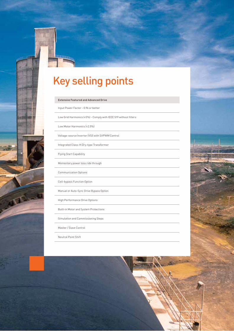
Simple and swift serviceTOOLS FREE MAINTENANCE
Removing filters for inspection is very easy. Just lift and remove. No tools are needed.
– While the filter is removed, safety of personnel is maintained by the mesh in the panel
– Set of filters included with every MVD order
No special tools are needed for installation and general maintenance.
– Set of basic tools, e.g. spanner, provided with every MVD order
Front and rear access.
– Option for front access only
8 M-Series MVD Drives www.aucom.com

Current valid value 15 A, switch peak 31 A before sync transfer
The motor current waveform during sync transfer
More flexibilityMANUAL OR AUTO-SYNC BYPASS
Operate the motor direct from mains supply bypassing the drive:
– Maximise efficiency (99.9%) for fixed or full speed applications after start up
– Provide operational redundancy while drive is being serviced
Using phase lock loop technology:
– Adjust and match the drive output with the grid: frequency, phase angle and amplitude
– Minimises or eliminates undesirable switching transient
Multi-motor Synchronous Transfer Function:
– Multi-motor synchronous transfer function allows users to start multiple (up to 4) MV motors sequentially in drive mode and control the last motor speed.
NOMINAL CURRENT SOFT STARTING
Utilise the drive for soft starting or soft stopping only.
– Full torque start
– Ability to start at motor nominal current
– Maximum efficiency during running with bypassed operation
– Operate with standard MV motor
– Reduced footprint compared to full standard drive
M-Series MVD Drives www.aucom.com 9

AUCOM TECHNICAL DATASHEET
Our medium voltage motor control specialists use advanced proprietary tools to specify the ideal AuCom medium voltage solution for your application. We provide a detailed technical datasheet including calculations for motor starting, heat dissipation, supply capacity, transformer & cable voltage drops, and selection of fuses and power factor correction.
Knowledge is powerFAULT RECORD INTERFACE
Real date and time stamped.
Each fault recorded includes:
– Fault time
– Fault name
– VFD running frequency during fault
– VFD output voltage during fault
– VFD output current during fault
Fault data is stored for up to 1 year. Clear automatically or manually.
– Can be saved to external USB storage.
TREND CURVE INTERFACE
Provide real-time curve and historical curve.
– Historical curve is recorded at 1s interval, up to 5 minutes.
– Historical curve data is stored automatically for 1 month. Clears automatically or manually.
– Historical curve data can be saved to external USB storage.
5 Hz sampling rate, up to 5 minutes rolling.
Trend curve interface
10 M-Series MVD Drives www.aucom.com

AuCom Interface Board Technology (IBT), a unique concept within the medium voltage motor control market, separates the core control system (including the controller and complex, time critical algorithmic processing) from the medium voltage power section.
100% GALVANIC ISOLATION
The interface board is located in a separate, dedicated section of the medium voltage compartment. Fibre optic wires connect the control and power sections of the drive through the interface board, eliminating the need for any copper wiring and providing complete galvanic isolation of the low voltage compartment.
Even safer with IBT technology
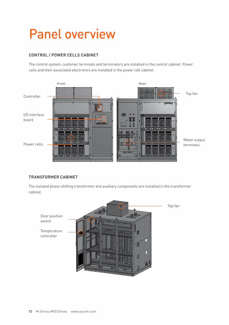
Top fan
Top fan
Door position switch
Temperature controller
(Front) (Rear)
Motor output terminals
I/O interface board
Power cells
Panel overviewCONTROL / POWER CELLS CABINET
The control system, customer terminals and terminators are installed in the control cabinet. Power cells and their associated electronics are installed in the power cell cabinet.
TRANSFORMER CABINET
The isolated phase shifting transformer and auxiliary components are installed in the transformer cabinet.
Controller
12 M-Series MVD Drives www.aucom.com

Specification Parameters
VFD rated power 210 – 28000 kVA *
For motor power 150 – 24000 kW *
Rated voltage 3.3 – 13.8 kV (-20% / +5%) *
Rated frequency 50 Hz / 60 Hz (-10% / +10%) *
Modulation technique SVPWM
Control power 400 V (customised)
Input power factor >0.96
Efficiency >96%, for variable frequency part >98%
Output frequency range 0 Hz – 80 Hz *
Frequency resolution 0.01 Hz / 0.002 Hz
Instantaneous over-current
protection150% protect immediately (customised )
Overload capability 120% ,125 s
Current limited protection 10%-150% (1000 ms – 3 s inverse time protection)
Analog inputThree ways 4 – 20 mA / 2 – 10 V
(excitation feedback 4 – 20 mA / 2 – 10 V included)
Analog output Four ways 4 – 20 mA (two ways fixed, two ways optional)
Host communicationIsolated RS485 interface, ModBus RTU,
Optional: Profibus DP, Industry Ethernet Protocol*
Acceleration and deceleration time 5 s – 1600 s (related to load)
DI/DO 14 inputs / 22 outputs
Environment temperature -5 – +45°C *
Storage / transportation
temperature-40 – +70°C *
Cooling Forced air cooling / water cooling
Humidity <95%, no condensation *
Altitude ≤1000 m *
Dust Non-conductive, no causticity, <6.5 mg / dm3 *
Protection level IP30 / 31 / 41 / 42 *
Cabinet colours RAL 7032*
* Please consult with AuCom for the information for other options.
Product specifications

MOTOR TYPE
Y = Asynchronous motor T = Synchronous motor
DRIVE CONTROL
Blank = Standard drive V = Vector control
DRIVE OPTION
Blank = Standard drive AFE = Active Front End BP = Bypassed
RATED OPERATIONAL VOLTAGE
V02 = 2.3kV V03 = 3.0 - 3.3kV V04 = 4.16kV V06 = 6.0 - 6.6kV V11 = 11kV V13 = 13.8kV
CURRENT RATING
0031 = 31 A 0304 = 304 A 0040 = 40 A 0340 = 340 A 0048 = 48 A 0400 = 400 A 0061 = 61 A 0425 = 425 A 0077 = 77 A 0500 = 500 A 0096 = 96 A 0550 = 550 A 0130 = 130 A 0600 = 600 A 0154 = 154 A 0660 = 660 A 0173 = 173 A 0750 = 750 A 0192 = 192 A 0800 = 800 A 0220 = 220 A 0960 = 960 A 0243 = 243 A 1200 = 1200 A 0275 = 275 A 1250 = 1250 A
MVD - 0 0 3 1 - V 0 3 - Y - X - X
Model code
Other solutions
Soft Start
Motor Protection
Current Range
Voltage Range
CSXi • • ≤ 200 A ≤ 575 VAC
EMX3 • • ≤ 2400 A ≤ 690 VAC
EMX4 • • ≤ 2430 A ≤ 1200 VAC
MVE • • ≤ 1700 A ≤ 13.8 kV
AuCom offers a complete range of soft starters. Whether you need a simple product for starting only, or a comprehensive motor control package, you can trust AuCom to offer a product to match.
14 M-Series MVD Drives www.aucom.com

Wat
er /
Was
tew
ater
Pow
er g
ener
atio
n
Pulp
/ Pa
per
Chem
ical
/ Pe
troc
hem
ical
Min
ing
Cem
ent /
Sto
ne
Woo
d pr
oces
sing
Bui
ldin
g te
chno
logy
Mar
ine
/ Off
sho
re
Indu
stry
/ Pr
oduc
tion
Pump ¢ ¢ ¢ ¢ ¢ ¢ ¢
Fan/Blower/Aerator ¢ ¢ ¢ ¢ ¢ ¢ ¢
Compressor ¢ ¢ ¢ ¢ ¢
Chiller ¢ ¢ ¢ ¢
Refiner ¢ ¢
Extruder ¢
Centrifuge ¢ ¢
Mill crusher ¢ ¢ ¢
Hacker ¢ ¢
Conveyor ¢ ¢ ¢ ¢
Roller ¢ ¢
Rotating converter ¢ ¢ ¢ ¢
Bow thruster ¢
Main propulsion ¢
A world of experience

The motor control specialistsAt AuCom our focus is exclusively on motor control. We provide a range of industry leading products utilising the latest technology.
A dedicated medium voltage laboratory with full manufacturing and on-site testing facility provides selectable voltage sources from 2.3 kV to 13.8 kV, pump load, electronically controlled test load and synchronous motor testing capabilities.
TESTING AND VERIFICATION
Our comprehensive MV testing routine is designed to guarantee that our products are safe and reliable. This process involves:
– Motor speed test
– Motor light load test
– Protection function test
– Acoustic noise test
– Speed tracking restart test
– Output dv / dt test
– Output common mode voltage test
– Output voltage range and imbalance test
– Output current range and imbalance test
We also offer factory acceptance testing (FAT) and third party test audits on request.
THE PROOF IS IN THE POWER UP
All AuCom MV drives run a motor at rated voltage before they leave the factory so we’re sure that you’re getting the performance we promised.
FULL TRACEABILITY
Automated testing routines verify operational performance and record results so that all necessary information is readily available in the rare event that things don’t go as planned.
THIRD PARTY CALIBRATION
Third party calibration professionals carry out regular calibration of all our equipment including test and measurement fixtures.
16 M-Series MVD Drives www.aucom.com

Description Design
IEC Standard Voltages IEC 60038
Electrical and Magnetic Devices IEC 60050 - 151
Power Electronics IEC 60050 - 551
Electric Power Transformer IEC 60076
Environmental Classifications, parts 1 - 3 IEC 60721 - 3
EMC with Industrial Plants Guideline IEC 61000 - 2 - 4
EMC Test and Measurement Techniques IEC 61000 - 4 - 7
Adjustable Speed Electrical Power Drive Systems IEC 61800 - 3
Code for Designation of Colours IEC 60757
Environmental Condition, Performance Ratings IEC 106
General specifications

The future starts with AuComWe develop motor control products for industrial applications across the world. Our focus on research and development, as well as manufacturing, supply and support, ensures that when you choose to work with AuCom, you’re working with a global leader. Almost 40 years of experience added to our expertise and ability means you can rely on us to get it right from the start.
OUR APPROACH
We start with a challenge or application, working with you to define and develop a solution that’s not only fit for purpose today, but fully supported into tomorrow.
OUR PARTNERS
We choose partners that are experts, not only in soft start and motor control, but in understanding the needs of their industry. We work closely with our partners to ensure customers receive only the best support and advice.
OUR PEOPLE
The power behind our success doesn’t rely on our innovative products alone. Our people play a pivotal role. That’s why, with AuCom, it’s always personal. Combining dedication and experience with ability and passion, we don’t just listen more closely, we draw on the breadth of our expertise to better understand your unique requirements and offer real solutions and ongoing support.
18 M-Series MVD Drives www.aucom.com

AuCom’s expertise and knowledge extends well beyond the products we make. We’re about helping you achieve efficient and effective control of your machines and processes no matter what the industry or application.
We’ve got you covered
© 2020 AuCom Electronics Ltd. All Rights Reserved. As AuCom is continuously improving its products it reserves the right to modify or change the specification of its products at any time without notice. The text, diagrams, images and any other literary or artistic works appearing in this document are protected by copyright. Users may copy some of the material for their personal reference but may not copy or use material for any other purpose without the prior consent of AuCom Electronics Ltd. AuCom endeavours to ensure that the information contained in this document including images is correct but does not accept any liability for error, omission or differences with the finished product.
710-22576-00A
New Zealand
123 Wrights Road, PO Box 80208, Christchurch 8440, New Zealand
T +64 3 338 8280 F +64 3 338 8104
China
203-1 JH Plaza, 2008 Huqingping Road, Shanghai 201702, China
T +86 21 5877 5178 F +86 21 5877 6378
Germany
Borsigstraße 6, 48324 Sendenhorst, Germany
T +49 2526 938800 F +49 2526 93880 100
Korea
501, Teheran-ro, Gangnam-gu, Seoul, South Korea
T +82 2 6673 3429
Middle East
Al Thanyah Fifth, Mazaya Business Avenue BB2, PO Box 338420
Jumeirah Lakes Towers, Dubai, UAE
T +971 4 430 7203
North America
Benshaw Inc,
615 Alpha Drive, Pittsburgh, PA 15238, USA
T +1 412 968 0100 F +1 412 968 5415
For more information and your local contact visit www.aucom.com