Embed Size (px)
Citation preview

IKMH100
Intel® Core™ i5-6200U 2.3 GHz, up to 2.8 GHz
M-Series Box PC
User Manual Version 1.0

USER MANUAL PREFACE
II IKMH100 M-SERIES BOX PC
PREFACE
Copyright Notice
No part of this document may be reproduced, copied, translated, or transmitted in any form or by any means, electronic or mechanical, for any purpose, without the prior written permission of the original manufacturer.
Trademark Acknowledgement
Brand and product names are trademarks or registered trademarks of their respective owners.
Disclaimer
We reserve the right to make changes, without notice, to any product, including circuits and/or software described or contained in this manual in order to improve design and/or performance. We assume no responsibility or liability for the use of the described product(s), conveys no license or title under any patent, copyright, or masks work rights to these products, and makes no representations or warranties that these products are free from patent, copyright, or mask work right infringement, unless otherwise specified. Applications that are described in this manual are for illustration purposes only. We make no representation or warranty that such application will be suitable for the specified use without further testing or modification.
Warranty We warrant that each of its products will be free from material and workmanship defects for a period of one year from the invoice date.(Standard is one year, extended warranty will need to discuss with our sales representatives. If the customer discovers a defect, we will, at its option, repair or replace the defective product at no charge to the customer, provided it is returned during the warranty period of one year, with transportation charges prepaid. The returned product must be properly packaged in its original packaging to obtain warranty service.
If the serial number and the product shipping data differ by over 30 days, the in-warranty service will be made according to the shipping date. In the serial numbers the third and fourth two digits give the year of manufacture, and the fifth digit means the month (e. g., with A for October, B for November and C for December).
For example, the serial number 1W16Axxxxxxxx means October of year 2016.

USER MANUAL PREFACE
IKMH100 M-SERIES BOX PC III
Customer Service
We provide a service guide as below for any problem by the following steps: First, contact your distributor, sales representative, or our customer service center for technical support if you need additional assistance.
You need to prepare the following information before you call: Product serial number Peripheral attachments Software (OS, version, application software, etc.) Detailed problem description The exact wording of any error messages
In addition, free technical support is available from our engineers every business day. We are always ready to give advice on application requirements or specific information on the installation and operation of any of our products. Please do not hesitate to call or e-mail us.

USER MANUAL PREFACE
IV IKMH100 M-SERIES BOX PC
Advisory Conventions
Four types of advisories are used throughout the user manual to provide helpful information or to alert you to the potential for hardware damage or personal injury. These are Notes, Important, Cautions, and Warnings. The following is an example of each type of advisory.
NOTE:
A note is used to emphasize helpful information
IMPORTANT:
An important note indicates information that is important for you to
know.
CAUTION
A Caution alert indicates potential damage to hardware and explains
how to avoid the potential problem.
WARNING!
An Electrical Shock Warning indicates the potential harm from electrical
hazards and how to avoid the potential problem.

USER MANUAL PREFACE
IKMH100 M-SERIES BOX PC V
Safety Precautions
WARNING!
Always completely disconnect the power from the device whenever
you work with the hardware. Do not make connections while the
power is on. Sensitive electronic components can be damaged by
sudden power surges.
CAUTION
Always ground yourself to remove any static charge before touching
the CPU card. Modern electronic devices are very sensitive to static
electric charges. As a safety precaution, use a grounding wrist strap
at all times. Place all electronic components in a static-dissipative
surface or static-shielded bag when they are not in the chassis.
Safety and Warranty
1. Please read these safety instructions carefully and keep this user manual for later
reference.
2. Please disconnect this equipment from any AC outlet before cleaning. Do not use
liquid or spray detergents for cleaning. Use a damp cloth.
3. For pluggable equipment, the power outlet must be installed near the equipment
and must be easily accessible.
4. Put this equipment on a reliable surface during installation. Dropping it or letting it
fall could cause damage.
5. Make sure the voltage of the power source is correct before connecting the
equipment to the power outlet.
6. Position the power cord so that people cannot step on it. Do not place anything
over the power cord.
7. If the equipment is not used for a long time, disconnect it from the power source to
avoid damage by transient over-voltage.
8. If any of the following situations arises, get the equipment checked by service
personnel:
A. The power cord or plug is damaged.
B. Liquid has penetrated into the equipment.
C. The equipment has been exposed to moisture.
D. The equipment does not work well, or you cannot get it to work according to
the user’s manual.
E. The equipment has been dropped and damaged.
F. The equipment has obvious signs of breakage


USER MANUAL ABOUT THIS USER MANUAL
I IKMH100 M-SERIES BOX PC
ABOUT THIS USER MANUAL
This User Manual provides information about using the Winmate® M-Series Box PC with
Intel® Core™ i5-6200U processor. The documentation set for the M -Series Box PC
provides information for specific user needs, and includes:
M-Series Box PC User Manual – contains detailed description on how to use the
Box PC, its components and features.
M-Series Quick Start Guide - describes how to get the device up and running.
NOTE:
Some pictures in this guide are samples and can differ from actual
product.
Document Revision History
Version Date Note
1.0 7-Mar-2017 Initial release


USER MANUAL CONTENTS
I IKMH100 M-SERIES BOX PC
CONTENTS PREFACE .................................................................................................................................................... II
ABOUT THIS USER MANUAL ....................................................................................................................... I
CHAPTER 1: GENERAL INFORMATION........................................................................................................ 2
1.1 INTRODUCTION .......................................................................................................................................... 2
1.2 PRODUCT FEATURES ................................................................................................................................... 2
1.3 PACKAGE CONTENTS ................................................................................................................................... 3
1.4 PHYSICAL DESCRIPTION ............................................................................................................................... 4
1.5 POWER BUTTON ........................................................................................................................................ 5
1.6 RESET BUTTON .......................................................................................................................................... 5
1.7 LED INDICATOR ......................................................................................................................................... 6
CHAPTER 2: HARDWARE INSTALLATION .................................................................................................... 8
2.1 CONNECTOR DESCRIPTION ........................................................................................................................... 8
2.1.1 Isolated DC in Connector ............................................................................................................... 8
2.1.2 Mic In, Line In and Line Out ........................................................................................................... 8
2.1.3 Serial Port Connector..................................................................................................................... 8
2.1.4 USB 3.0 Connector ......................................................................................................................... 9
2.1.5 VGA Output Connector .................................................................................................................. 9
2.1.6 HDMI Output Connector ............................................................................................................... 9
2.1.7 Giga LAN Connector .................................................................................................................... 10
2.2 CONFIGURING SERIAL PORT SETTINGS .......................................................................................................... 11
2.3 HARDWARE INSTALLATION ......................................................................................................................... 12
2.3.1 Hard Disk Replacement ............................................................................................................... 12
2.3.2 PCI Card, RAM, Internal SSD, Fuse Replacement ......................................................................... 13
2.3.3 Expansion Slot Replacement (Preliminary) .................................................................................. 15
CHAPTER 3: AMI UEFI BIOS SETUP .......................................................................................................... 17
3.1 WHEN AND HOW TO USE BIOS SETUP ........................................................................................................ 17
3.2 BIOS FUNCTIONS .................................................................................................................................... 18
3.2.1 Main Menu .................................................................................................................................. 19
3.2.2 Advanced Menu .......................................................................................................................... 20
3.2.3 Chipset Menu .............................................................................................................................. 33
3.2.4 Security Menu ............................................................................................................................. 40
3.2.5 Boot Menu................................................................................................................................... 43
3.2.6 Save&Exit .................................................................................................................................... 45
USER MANUAL CONTENTS
II IKMH100 M-SERIES BOX PC
3.3 USING RECOVERY WIZARD TO RESTORE COMPUTER ........................................................................................ 47
3.4 HOW TO ENABLE WATCHDOG ..................................................................................................................... 49
CHAPTER 4: DRIVER INSTALLATION ......................................................................................................... 52
4.1 CHIPSET DRIVER INSTALLATION ................................................................................................................... 52
4.2 GRAPHIC DRIVER INSTALLATION .................................................................................................................. 55
4.3 ME AND NET FRAMEWORK 1.1 DRIVER INSTALLATION ................................................................................... 59
4.4 AUDIO DRIVER INSTALLATION ..................................................................................................................... 64
4.5 LAN DRIVER INSTALLATION ........................................................................................................................ 66
4.6 RST DRIVER INSTALLATION ......................................................................................................................... 69
4.7 MICROSOFT .NET FRAMEWORK DRIVER INSTALLATION ................................................................................... 73
4.8 WATCHDOG DRIVER INSTALLATION .............................................................................................................. 75
CHAPTER 5: TECHNICAL SUPPORT ........................................................................................................... 80
5.1 SOFTWARE DEVELOPER SUPPORT ................................................................................................................ 80
5.2 PROBLEM REPORT FORM ........................................................................................................................... 81
APPENDIX A: PCIE CARD DIMENSIONS .................................................................................................... 83
APPENDIX B: PRODUCT SPECIFICATIONS ................................................................................................. 85

USER MANUAL CHAPTER 1 GENERAL INFORMATION
1 IKMH100 M-SERIES BOX PC
GENERAL INFORMATION This chapter includes IKMH100 M-Series Box
PC background information.
USER MANUAL CHAPTER 1 GENERAL INFORMATION
IKMH100 M-SERIES BOX PC 2
CHAPTER 1: GENERAL INFORMATION
This chapter includes Winmate® IKMH100 M-Series Box PC background information such as features, hardware specification, dimensions and appearance.
1.1 Introduction
Thank you for choosing the Winmate® IKMH100 M-Series Box PC. This is versatile and
cost-effective solution for your industrial needs. Intel® Core ™ i5-6200U 2.70 GHz
(Skylake) processor onboard with fanless cooling system assures steady performance and
silent functioning. Motherboard offers various inputs/ output connectors: two Ethernet
ports, four USB3.0, HDMI and VGA outputs, two serial ports and one 2.5” SSD Bay.
M-Series Box PC perfectly fits in applications where total costs of ownership (TCO) and
quick recovery of failure is important. The flexible system design provides easy access to
components and can be serviced by local maintenance team.
Versatile, easy-to-service and upgradable IKMH100 offers the best solution for industrial
and building automation.
1.2 Product Features
Winmate® IKMH100 M-Series Box PC has the following features:
Intel® Core™ i5-6200U 2.3 GHz, up to 2.8 GHz
Modular design
Auto detection of the connected display, No settings necessary
Quick & Easy Replaceable Hard Disk Design, No Tools needed
Support wide range 9-29V isolation DC input
Optional with Modular front Display as a Panel PC
Expansion slot for PCIex4
Quick & Easy Removable 2.5” SSD Bay Slot

USER MANUAL CHAPTER 1 GENERAL INFORMATION
3 IKMH100 M-SERIES BOX PC
1.3 Package Contents
Carefully remove the box and unpack your IKMH100 M-Series Box PC. Please check if
all the items listed below are inside your package. If any of these items are missing
or damaged contact us immediately.
Standard factory shipment list:
IKMH100 Box PC Driver CD& User Manual Quick Start Guide
(Hardcopy)
Varies by product
specifications 9171111I102Z 915211101023
Open Wire Cable Power Cord
AC Adapter + Terminal
Block
(12V/ 80W)
94EL02X020E0 Varies by country 90PO12080007
USER MANUAL CHAPTER 1 GENERAL INFORMATION
IKMH100 M-SERIES BOX PC 4
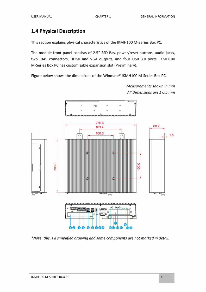
1.4 Physical Description
This section explains physical characteristics of the IKMH100 M-Series Box PC.
The module front panel consists of 2.5” SSD Bay, power/reset buttons, audio jacks,
two RJ45 connectors, HDMI and VGA outputs, and four USB 3.0 ports. IKMH100
M-Series Box PC has customizable expansion slot (Preliminary).
Figure below shows the dimensions of the Winmate® IKMH100 M-Series Box PC.
Measurements shown in mm
All Dimensions are ± 0.5 mm
*Note: this is a simplified drawing and some components are not marked in detail.
USER MANUAL CHAPTER 1 GENERAL INFORMATION
5 IKMH100 M-SERIES BOX PC
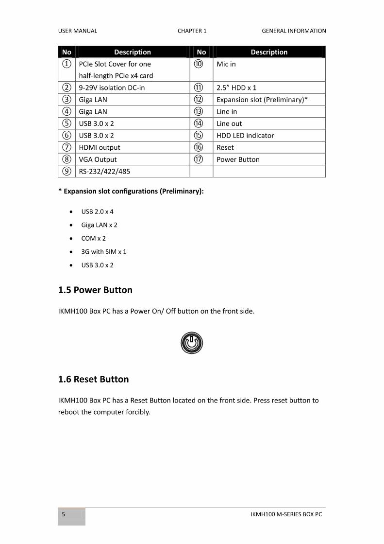
No Description No Description
① PCIe Slot Cover for one
half-length PCIe x4 card
⑩ Mic in
② 9-29V isolation DC-in ⑪ 2.5” HDD x 1
③ Giga LAN ⑫ Expansion slot (Preliminary)*
④ Giga LAN ⑬ Line in
⑤ USB 3.0 x 2 ⑭ Line out
⑥ USB 3.0 x 2 ⑮ HDD LED indicator
⑦ HDMI output ⑯ Reset
⑧ VGA Output ⑰ Power Button
⑨ RS-232/422/485
* Expansion slot configurations (Preliminary):
USB 2.0 x 4
Giga LAN x 2
COM x 2
3G with SIM x 1
USB 3.0 x 2
1.5 Power Button
IKMH100 Box PC has a Power On/ Off button on the front side.
1.6 Reset Button
IKMH100 Box PC has a Reset Button located on the front side. Press reset button to
reboot the computer forcibly.

USER MANUAL CHAPTER 1 GENERAL INFORMATION
IKMH100 M-SERIES BOX PC 6
1.7 LED Indicator
The IKMH100 provides one HDD LED indicator for status monitoring.
LED Indicator:
LED Indicator Color Description
HDD
Off Slot is empty; drive is not yet discovered by
the system.
Green HDD operating normally.

USER MANUAL CHAPTER 2 HARDWARE INSTALLATION
7 IKMH100 M-SERIES BOX PC
HARDWARE INSTALLATION This chapter provides information on how to use
jumpers and connectors on the motherboard, and
the IKMH100 M-Series Box PC hardware
specifications and installation instruction.

USER MANUAL CHAPTER 2 HARDWARE INSTALLATION
IKMH100 M-SERIES BOX PC 8
CHAPTER 2: HARDWARE INSTALLATION
This chapter provides information on external connectors on IKMH100 M-Series Box PC and hardware specifications and installation instruction.
2.1 Connector Description
This section includes I/O side connectors and its pinouts.
2.1.1 Isolated DC in Connector
IKMH100 has a 3pin terminal block that accepts 9~29V DC input.
2.1.2 Mic In, Line In and Line Out
2.1.3 Serial Port Connector
The IKMH100 Box PC uses D-SUB 9pin connector to connect serial interfaces.
Serial port settings can be configured for RS-232, RS-422 or RS-485 by jumpers. Refer to Ch.2, Configuring Serial Port Settings section of this user manual for the instruction on how to configure serial port settings.
Voltage
Minimum Voltage 9V Maximum Voltage 29V
Color Signal Name
Mic In Mic in
Blue Line in
Green Line out
Pin № RS-232 (Default) RS-422 RS-485
1 DCD TxD- D-
2 RXD TxD+ D+
3 TXD RxD+ NC
4 DTR RxD- NC
5 GND GND GND
6 DSR NC NC
7 RTS NC NC
8 CTS NC NC
9 RI NC NC
USER MANUAL CHAPTER 2 GETTING STARTED
9 IKMH100 M-SERIES BOX PC
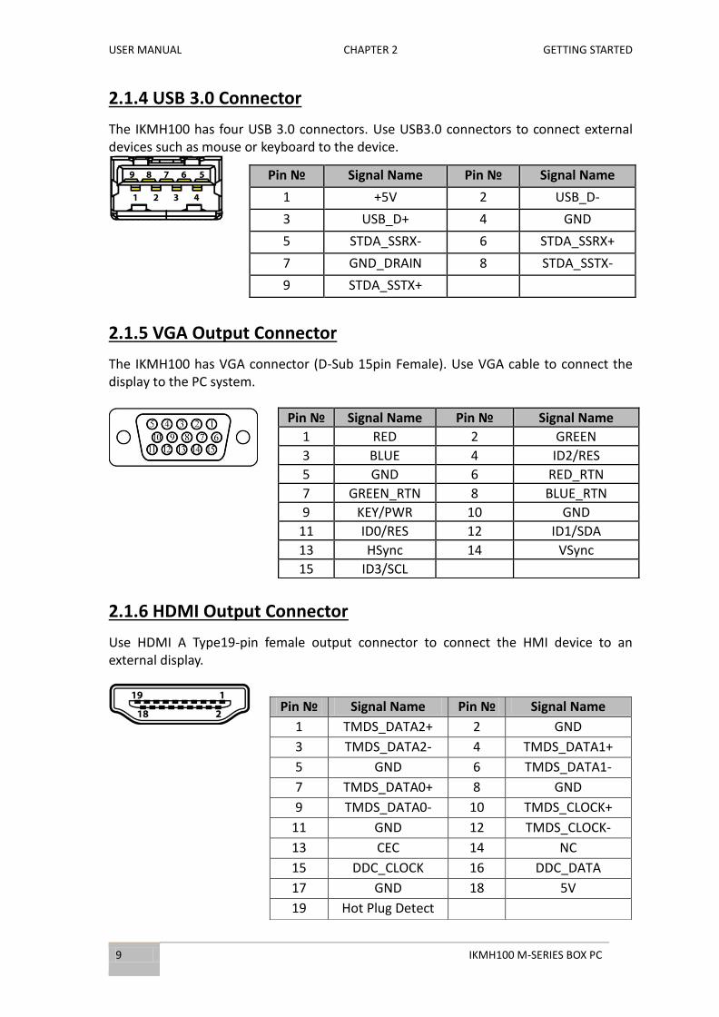
2.1.4 USB 3.0 Connector
The IKMH100 has four USB 3.0 connectors. Use USB3.0 connectors to connect external devices such as mouse or keyboard to the device.
2.1.5 VGA Output Connector
The IKMH100 has VGA connector (D-Sub 15pin Female). Use VGA cable to connect the display to the PC system.
2.1.6 HDMI Output Connector
Use HDMI A Type19-pin female output connector to connect the HMI device to an external display.
Pin № Signal Name Pin № Signal Name
1 +5V 2 USB_D-
3 USB_D+ 4 GND
5 STDA_SSRX- 6 STDA_SSRX+
7 GND_DRAIN 8 STDA_SSTX-
9 STDA_SSTX+
Pin № Signal Name Pin № Signal Name
1 RED 2 GREEN
3 BLUE 4 ID2/RES
5 GND 6 RED_RTN
7 GREEN_RTN 8 BLUE_RTN
9 KEY/PWR 10 GND
11 ID0/RES 12 ID1/SDA
13 HSync 14 VSync
15 ID3/SCL
Pin № Signal Name Pin № Signal Name
1 TMDS_DATA2+ 2 GND
3 TMDS_DATA2- 4 TMDS_DATA1+
5 GND 6 TMDS_DATA1-
7 TMDS_DATA0+ 8 GND
9 TMDS_DATA0- 10 TMDS_CLOCK+
11 GND 12 TMDS_CLOCK-
13 CEC 14 NC
15 DDC_CLOCK 16 DDC_DATA
17 GND 18 5V
19 Hot Plug Detect

USER MANUAL CHAPTER 2 HARDWARE INSTALLATION
IKMH100 M-SERIES BOX PC 10
2.1.7 Giga LAN Connector
The IKMH100 equipped with one RJ45 10/100/1000 Mbps Ethernet interface for connecting to the internet.
Pin № Signal Name Pin № Signal Name
1 TX1+ 2 TX1-
3 TX2+ 4 TX2-
5 TX3+ 6 TX3-
7 TX4+ 8 TX4-

USER MANUAL CHAPTER 2 GETTING STARTED
11 IKMH100 M-SERIES BOX PC
2.2 Configuring Serial Port Settings
Serial Port COM1 can be configured for RS-232, RS-422 or RS-485. Jumpers are located
on the motherboard. You need to open the housing in order to access the jumpers.
CAUTION/ ATTENTION It is recommended to use factory jumper settings. Opening the housing when it is sealed may damage the device and its parts. Il est recommandé d’utiliser la configuration d’usine de cavalier. Ouvrir le chassis lorsqu’il est scellé peut endommagé l’appareil et ses pièces.
Note:
A pair of needle nose pliers may be helpful when working with jumpers. If
you have any doubts about the best hardware configuration for your
application, contact your local distributor or sales representative before
you make any changes. Generally, you simply need a standard cable to
make most connections.
The jumper setting diagram is shown below. When the jumper cap is placed on both pins, the jumper is SHORT. The illustration below shows a 3-pin jumper; pins 1 and 2 are short. If you remove the jumper cap, the jumper is OPEN.
PIN 1-2 SHORT PIN 3 OPEN
Both Jumper 8 and Jumper 9 allow setting the Serial Port COM1 configuration. Refer to
the table below for PIN assignment.
Example: To make RS-232 Settings, set the Jumper 8 Pin 1-2 to the SHORT position, and
Jumper 9 Pin1-2, 4-5, 7-8, 10-11 to the SHORT position.
USER MANUAL CHAPTER 2 HARDWARE INSTALLATION
IKMH100 M-SERIES BOX PC 12
2.3 Hardware Installation
This section explains how to replace HDD/SDD, install PCI Card/ RAM/ Internal SSD,
and replace fuses on the IKMH100 M-Series Box PC.
WARNING!
Switch off the power and unplug the power cord. Each time the
IKMH100 M-Series Box PC is serviced, users should be aware of this
condition.
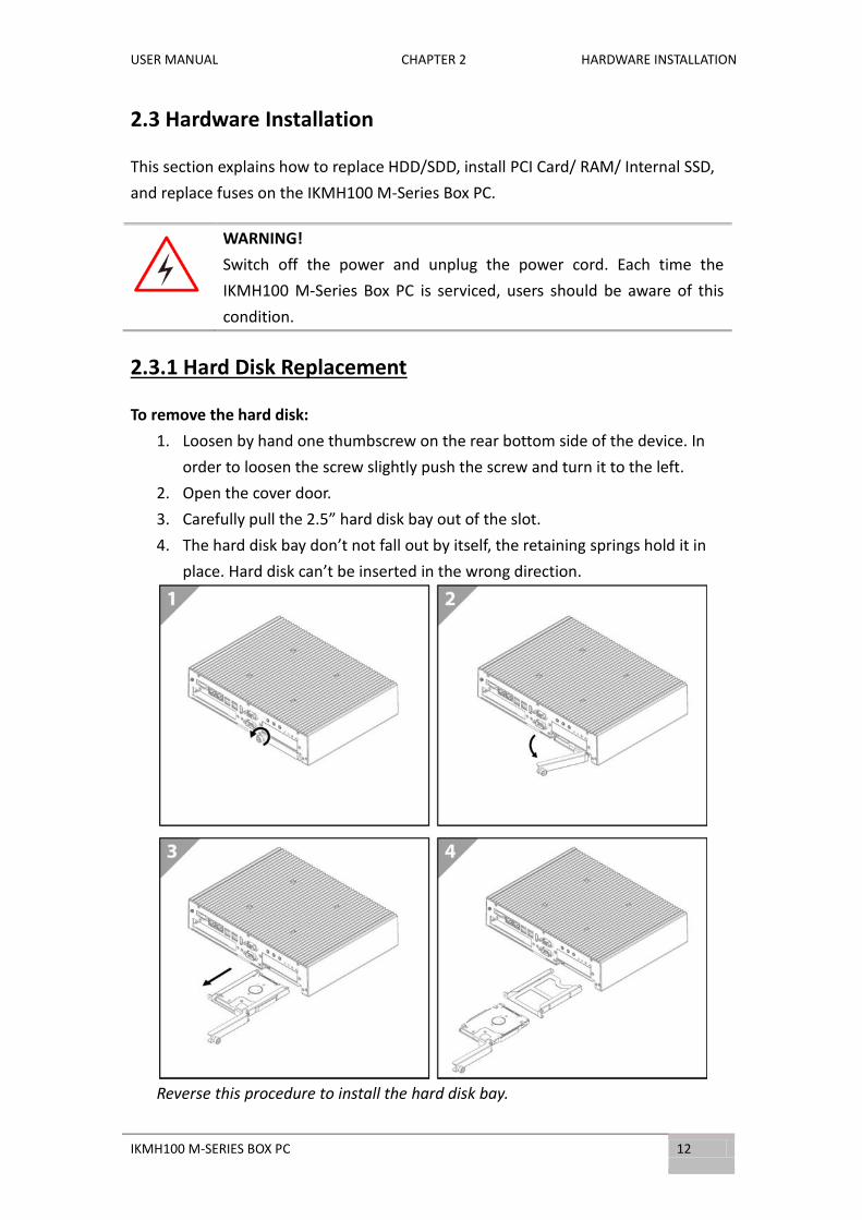
2.3.1 Hard Disk Replacement
To remove the hard disk:
1. Loosen by hand one thumbscrew on the rear bottom side of the device. In
order to loosen the screw slightly push the screw and turn it to the left.
2. Open the cover door.
3. Carefully pull the 2.5” hard disk bay out of the slot.
4. The hard disk bay don’t not fall out by itself, the retaining springs hold it in
place. Hard disk can’t be inserted in the wrong direction.
Reverse this procedure to install the hard disk bay.
USER MANUAL CHAPTER 2 HARDWARE INSTALLATION
13 IKMH100 M-SERIES BOX PC
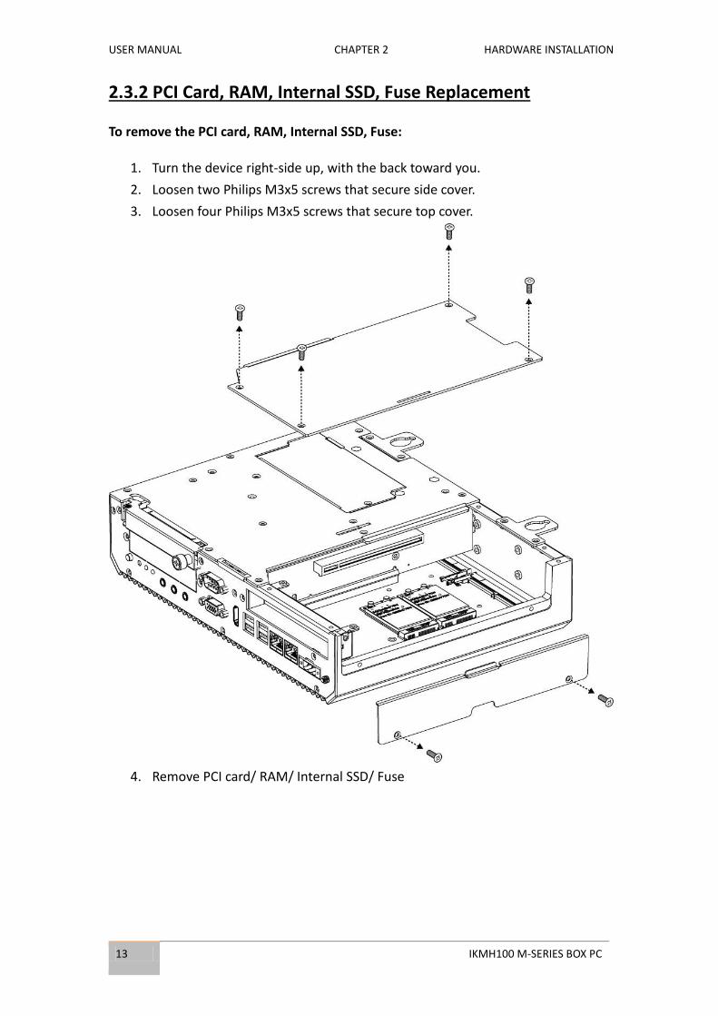
2.3.2 PCI Card, RAM, Internal SSD, Fuse Replacement
To remove the PCI card, RAM, Internal SSD, Fuse:
1. Turn the device right-side up, with the back toward you.
2. Loosen two Philips M3x5 screws that secure side cover.
3. Loosen four Philips M3x5 screws that secure top cover.
4. Remove PCI card/ RAM/ Internal SSD/ Fuse

USER MANUAL CHAPTER 2 HARDWARE INSTALLATION
IKMH100 M-SERIES BOX PC 14
Reverse this procedure to install the PCI card/ RAM/ Internal SSD/ Fuse.

USER MANUAL CHAPTER 2 HARDWARE INSTALLATION
15 IKMH100 M-SERIES BOX PC
2.3.3 Expansion Slot Replacement (Preliminary)
IKMH100 M-Series Box PC has customizable expansion slot.
To replace expansion slot:
1. Undo two screws that secure expansion slot to the Box PC.
2. Remove the slot.
3. Replace the slot with a new one (if needed).
Reverse this procedure to install the expansion slot.
USER MANUAL CHAPTER 3 AMI UEFI BIOS SETUP
IKMH100 M-SERIES BOX PC 16
AMI UEFI BIOS SETUP BIOS Setup Utility is a program for configuration
basic Input / Output system settings of the
computer for optimum use. This chapter provides
information on how to use BIOS setup, its
functions and menu.
USER MANUAL CHAPTER 5 AMI UEFI BIOS SETUP
17 IKMH100 M-SERIES BOX PC
CHAPTER 3: AMI UEFI BIOS SETUP
BIOS Setup Utility is a program for configuration basic Input / Output system settings of the computer for optimum use. This chapter provides information on how to use BIOS setup, its functions and menu.
3.1 When and How to Use BIOS Setup
To enter the BIOS setup, you need to connect an external USB keyboard, press <Del> key
when the prompt appears on the screen during start up. The prompt screen shows only
few seconds, you need to press <Del> key quickly. If the message disappears before your
respond, restart the system by turning it OFF and ON, and enter the BIOS again.
IMPORTANT:
Updated BIOS version may be published after the manual released.
Check the latest version of BIOS on the website.
Run BIOS setup utility for:
1. Error message on screen indicates to check BIOS setup
2. Restoring the factory default settings.
3. Modifying the specific hardware specifications
4. Necessity to optimize specifications

USER MANUAL CHAPTER 3 AMI UEFI BIOS SETUP
IKMH100 M-SERIES BOX PC 18
3.2 BIOS Functions
BIOS Navigation Keys
BIOS navigation keys for keyboard control are listed below.
The following keys are enabled during POST:
Key Function
Del Enters the BIOS setup menu.
F7 Display the boot menu. Lists all bootable devices that are
connected to the system. With cursor ↑and cursor ↓and by
pressing <ENTER>, select the device used for the boot.
Pause Pressing the [Pause] key stops the POST. Press any other key to
resume the POST.
The following Keys can be used after entering the BIOS Setup.
Key Function
F1 General Help
F2 Previous Values
F3 Optimized Defaults
F4 Save & Exit
Esc Exit
+/- Change Opt.
Enter Select or execute command
Cursor ↑ Moves to the previous item
Cursor ↓ Goes to the next item
Cursor ← Moves to the previous item
Cursor → Goes to the next item
NOTE:
You can press the F1, F2, F3, F4, –/+, and Esc keys by connecting a USB
keyboard to your device.
For items marked ► press <Enter> for more options.

USER MANUAL CHAPTER 5 AMI UEFI BIOS SETUP
19 IKMH100 M-SERIES BOX PC
3.2.1 Main Menu
When you enter BIOS setup, the first menu that appears on the screen is the main
menu.It contains the system information including BIOS version, processor RC version,
system language, time, and date. Immediately after the [DEL] key is pressed during
startup, the main BIOS setup menu appears.
USER MANUAL CHAPTER 3 AMI UEFI BIOS SETUP
IKMH100 M-SERIES BOX PC 20
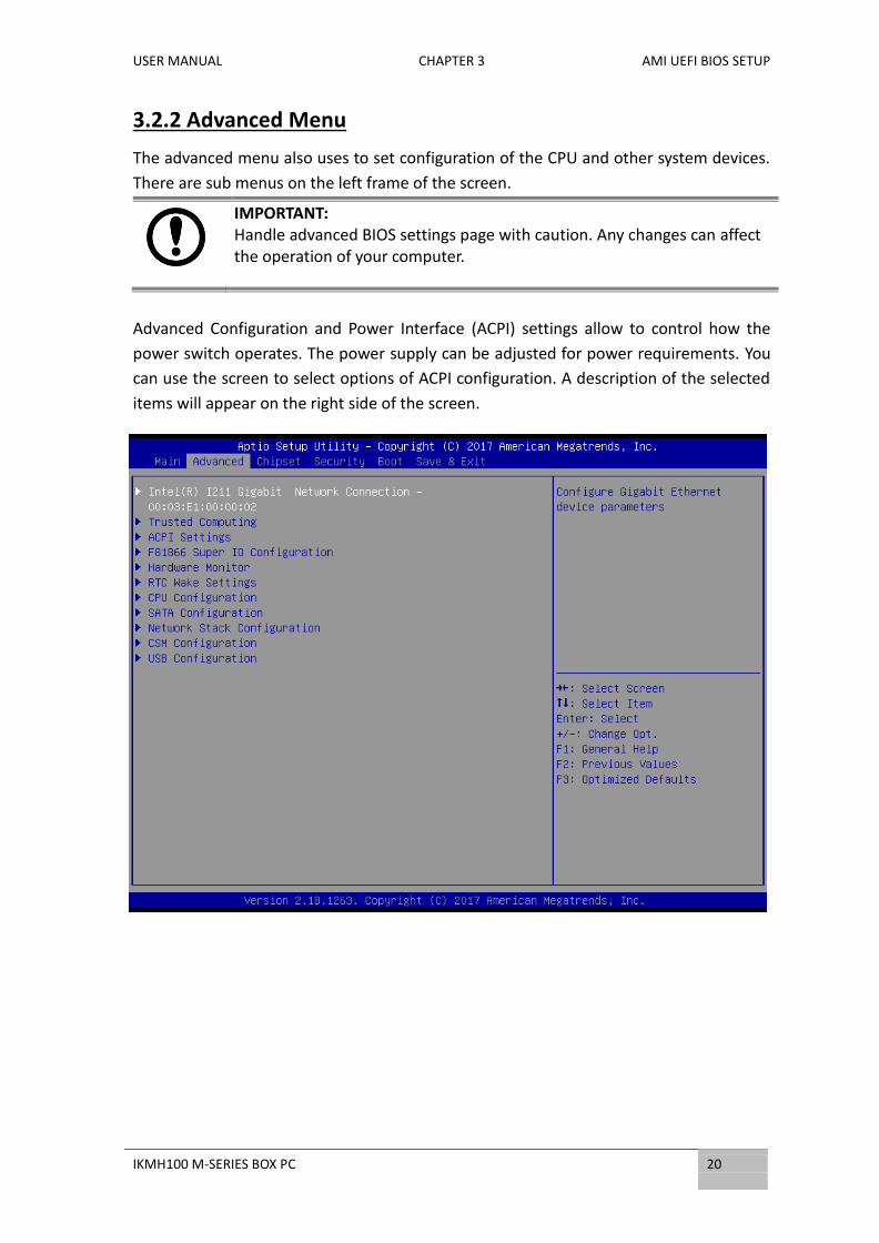
3.2.2 Advanced Menu
The advanced menu also uses to set configuration of the CPU and other system devices.
There are sub menus on the left frame of the screen.
IMPORTANT: Handle advanced BIOS settings page with caution. Any changes can affect the operation of your computer.
Advanced Configuration and Power Interface (ACPI) settings allow to control how the
power switch operates. The power supply can be adjusted for power requirements. You
can use the screen to select options of ACPI configuration. A description of the selected
items will appear on the right side of the screen.
USER MANUAL CHAPTER 5 AMI UEFI BIOS SETUP
21 IKMH100 M-SERIES BOX PC
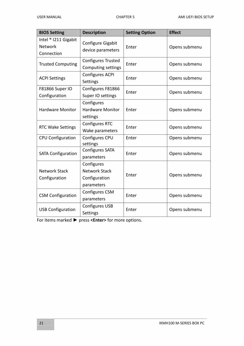
BIOS Setting Description Setting Option Effect
Intel ® I211 Gigabit
Network
Connection
Configure Gigabit
device parameters Enter Opens submenu
Trusted Computing Configures Trusted
Computing settings Enter Opens submenu
ACPI Settings Configures ACPI
Settings Enter Opens submenu
F81866 Super IO
Configuration
Configures F81866
Super IO settings Enter Opens submenu
Hardware Monitor
Configures
Hardware Monitor
settings
Enter Opens submenu
RTC Wake Settings Configures RTC
Wake parameters Enter Opens submenu
CPU Configuration Configures CPU settings
Enter Opens submenu
SATA Configuration Configures SATA
parameters Enter Opens submenu
Network Stack
Configuration
Configures
Network Stack
Configuration
parameters
Enter Opens submenu
CSM Configuration Configures CSM
parameters Enter Opens submenu
USB Configuration Configures USB
Settings Enter Opens submenu
For items marked ► press <Enter> for more options.

USER MANUAL CHAPTER 3 AMI UEFI BIOS SETUP
IKMH100 M-SERIES BOX PC 22
3.2.2.1 CPU Configuration
CPU Configuration allows you to change CPU settings. Use key arrows to navigate
through the menu.
BIOS Setting Description Setting
Option Effect
Hyper-threading
Hyper-threading is a
function in processors
that speeds up
computer
performance.
Enable/
Disable
Enables or Disables
this function
Execute Disabled
Bit
EDB is a
hardware-based
security component
used in the central
processing unit (CPU)
to separate areas of a
memory as storage of
processor instructions
or as storage of data.
Enable
Reduces a computer
system's, or a server’s,
vulnerability to viruses
and malicious code
attacks
Disable Increases the risk to
be infected by viruses

USER MANUAL CHAPTER 5 AMI UEFI BIOS SETUP
23 IKMH100 M-SERIES BOX PC
Intel Virtualization
Technology
Enables a CPU to act
as if you have several
independent
computers, in order
to enable several
operating systems to
run at the same time
on the same machine.
Enable/
Disable
Enable or disable this
function
Boot Performance Mode
This feature selects the performance state the BIOS will set before the OS hand-off.
Auto Auto mode
Standard
Allows processor cores to run at the frequency recommended by the manufacturer.
Turbo
Allows processor cores to run faster than the frequency recommended by the manufacturer.
EIST
Enhanced Intel
SpeedStep
Technology gives your
OS the ability to
switch the processor's
speed and voltage up
and down, to
preserve power when
not much is being
computed.
Enabled/ Disabled
Enable or disable this function
Turbo Mode
Adjusts the power and clock speed of processor cores as needed to better match processor power to your needs.
Enabled/ Disabled
Enable or disable this function
CPU C states Configure CPU C
states parameters Enabled/ Disabled
Enable or disable this function
CPU DTS
Digital Thermal
Sensors (DTS)
parameters.
Enabled/ Disabled
Enable or disable this function

USER MANUAL CHAPTER 3 AMI UEFI BIOS SETUP
IKMH100 M-SERIES BOX PC 24
3.2.2.2 Trusted Computing
BIOS Setting Description Setting Option Effect
Security Device Support
Enable or disable BIOS support for security device. O.S. will not show Security Device. TCG EFI protocol and INT1A interface will not be available
Enabled/ Disabled Enable or disable this function.
TPM State Trusted Platform Module (TPM) parameters.
Enabled/ Disabled Enable or disable this function.
Pending operation Pending operation parameters
None Shows the number of pending operations
Device Select Selects the device Auto
USER MANUAL CHAPTER 5 AMI UEFI BIOS SETUP
25 IKMH100 M-SERIES BOX PC
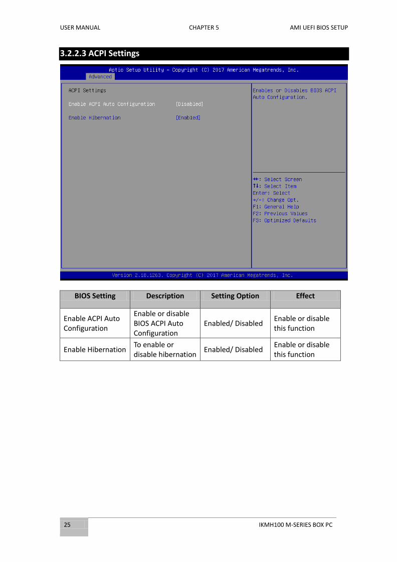
3.2.2.3 ACPI Settings
BIOS Setting Description Setting Option Effect
Enable ACPI Auto Configuration
Enable or disable BIOS ACPI Auto Configuration
Enabled/ Disabled Enable or disable this function
Enable Hibernation To enable or disable hibernation
Enabled/ Disabled Enable or disable this function

USER MANUAL CHAPTER 3 AMI UEFI BIOS SETUP
IKMH100 M-SERIES BOX PC 26
3.2.2.4 F81866 Super IO Configuration
BIOS Setting Description Setting Option Effect
Serial Port 1,2 Configuration
Set Parameters of Serial Ports. User can Enable/Disable the serial port and select optimal settings for the super IO Device.
Enabled/ Disabled Default: Enable
Enable or disable Serial Port (COM)
Watch Dog Timer Select
This watchdog timer can be used to monitor system software operation and take corrective action if the software fails to function after the programmed period.
Enabled/ Disabled
Enable or disable this function
USER MANUAL CHAPTER 5 AMI UEFI BIOS SETUP
27 IKMH100 M-SERIES BOX PC
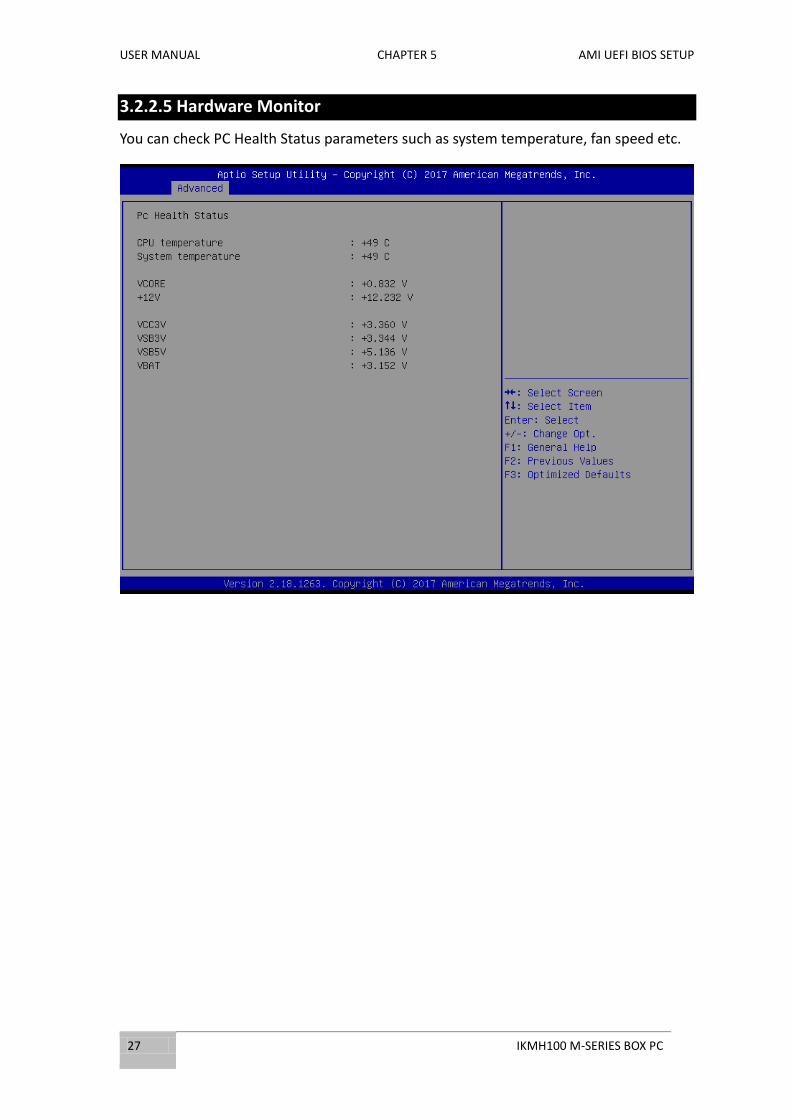
3.2.2.5 Hardware Monitor
You can check PC Health Status parameters such as system temperature, fan speed etc.

USER MANUAL CHAPTER 3 AMI UEFI BIOS SETUP
IKMH100 M-SERIES BOX PC 28
3.2.2.6 RTC Wake Settings
BIOS Setting Description Setting Option Effect
Wake system from S5
Configure wake from full shutdown and boot mode (S5) system setting
Enabled/ Disabled
Enable or disable this function. When enabled, the system will wake on full shutdown and boot mode.
USER MANUAL CHAPTER 5 AMI UEFI BIOS SETUP
29 IKMH100 M-SERIES BOX PC
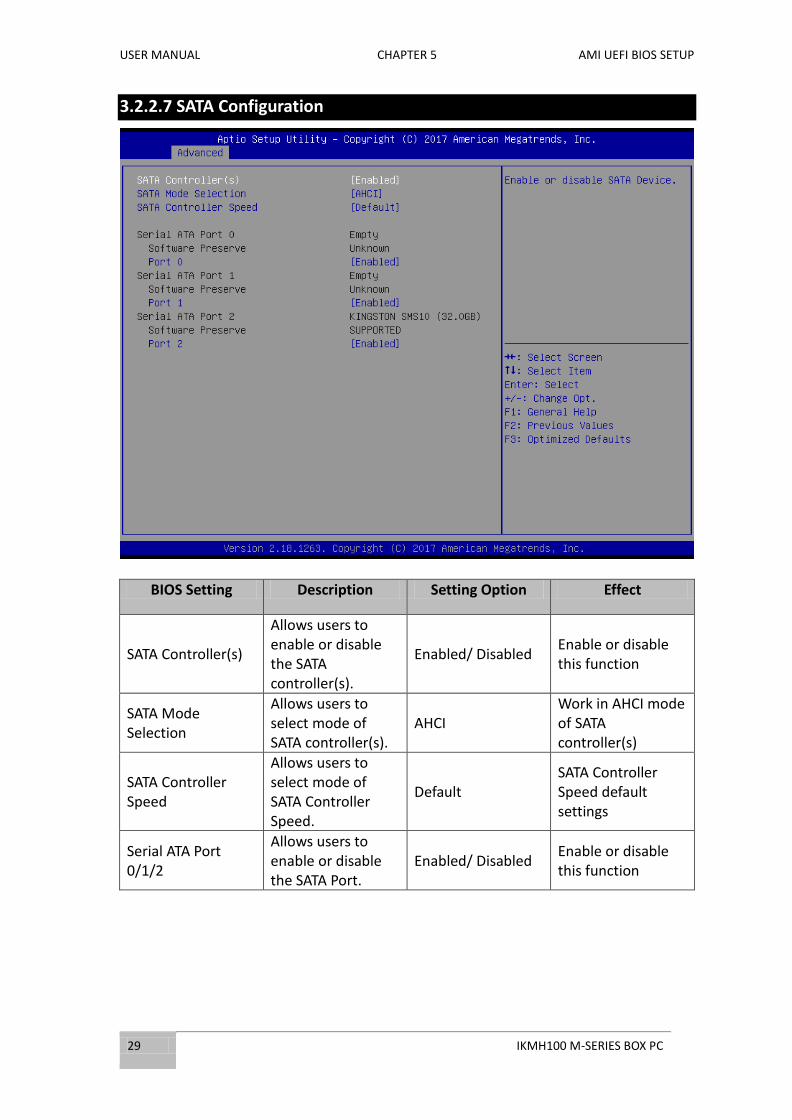
3.2.2.7 SATA Configuration
BIOS Setting Description Setting Option Effect
SATA Controller(s)
Allows users to enable or disable the SATA controller(s).
Enabled/ Disabled Enable or disable this function
SATA Mode Selection
Allows users to select mode of SATA controller(s).
AHCI Work in AHCI mode of SATA controller(s)
SATA Controller Speed
Allows users to select mode of SATA Controller Speed.
Default SATA Controller Speed default settings
Serial ATA Port 0/1/2
Allows users to enable or disable the SATA Port.
Enabled/ Disabled Enable or disable this function
USER MANUAL CHAPTER 3 AMI UEFI BIOS SETUP
IKMH100 M-SERIES BOX PC 30
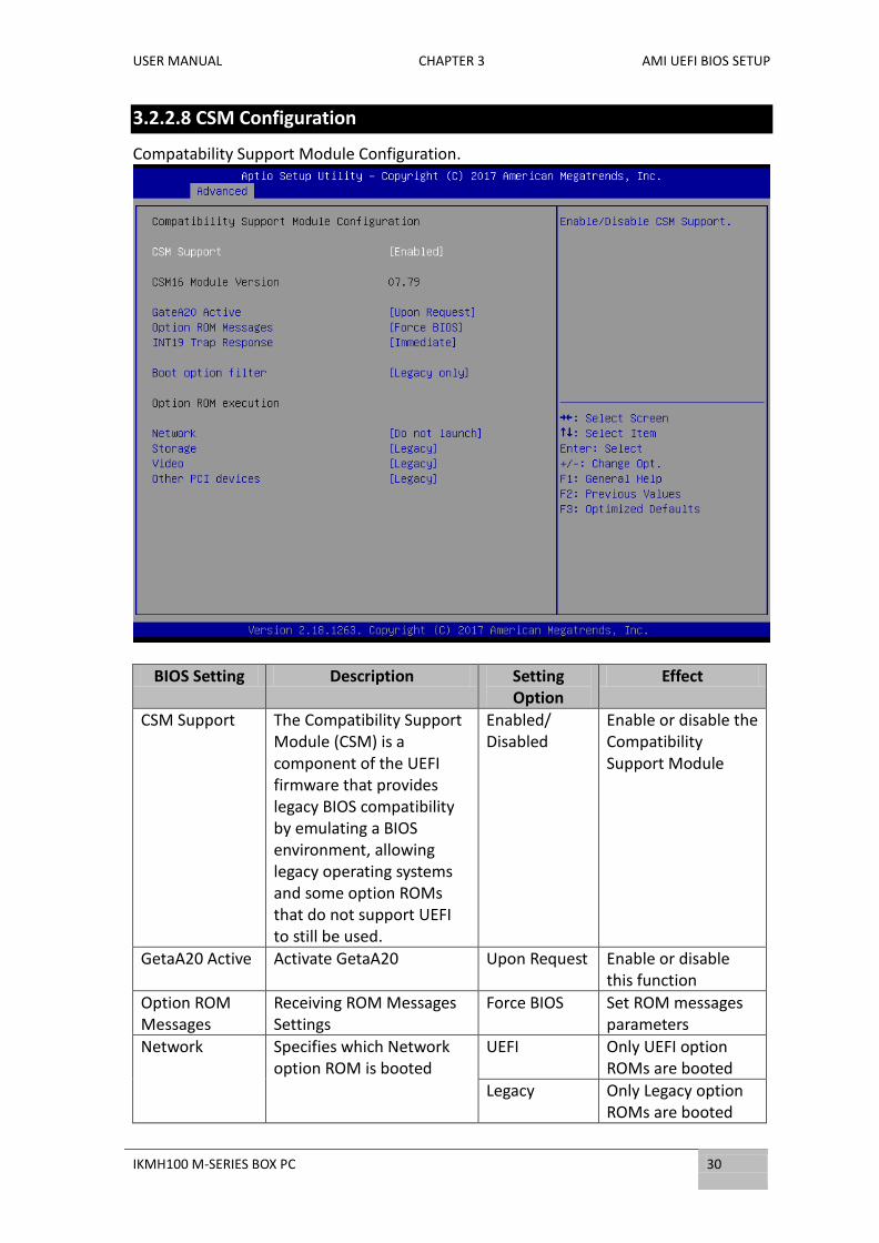
3.2.2.8 CSM Configuration
Compatability Support Module Configuration.
BIOS Setting Description Setting Option
Effect
CSM Support The Compatibility Support Module (CSM) is a component of the UEFI firmware that provides legacy BIOS compatibility by emulating a BIOS environment, allowing legacy operating systems and some option ROMs that do not support UEFI to still be used.
Enabled/ Disabled
Enable or disable the Compatibility Support Module
GetaA20 Active Activate GetaA20 Upon Request Enable or disable this function
Option ROM Messages
Receiving ROM Messages Settings
Force BIOS Set ROM messages parameters
Network Specifies which Network option ROM is booted
UEFI Only UEFI option ROMs are booted
Legacy Only Legacy option ROMs are booted
USER MANUAL CHAPTER 5 AMI UEFI BIOS SETUP
31 IKMH100 M-SERIES BOX PC
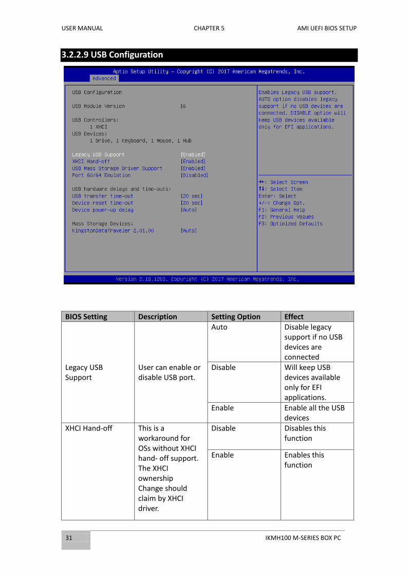
3.2.2.9 USB Configuration
BIOS Setting Description Setting Option Effect
Legacy USB Support
User can enable or disable USB port.
Auto Disable legacy support if no USB devices are connected
Disable Will keep USB devices available only for EFI applications.
Enable Enable all the USB devices
XHCI Hand‐off This is a workaround for OSs without XHCI hand‐ off support. The XHCI ownership Change should claim by XHCI driver.
Disable Disables this function
Enable
Enables this function

USER MANUAL CHAPTER 3 AMI UEFI BIOS SETUP
IKMH100 M-SERIES BOX PC 32
EHCI Hand‐off This is a workaround for OSs without ECHI hand‐ off support. The EHCI ownership change should be claimed by EHCI driver.
*Disabled
Disables this function
Enable Enables this function
USB Mass Storage Driver Support
User can Enable or disable USB mass storage driver support.
Disable Disables this function
Enable Enables this function
USB Transfer time‐ out
The time‐out value for control, bulk, and interrupt transfers.
1 Sec 5 Sec 10 Sec *20 Sec
Depends on the time‐out value
Device Reset time‐ out
USB mass storage device start unit command time‐ out.
10 Sec *20 Sec 30 Sec 40 Sec
Depends on the time‐out value
Device power‐up delay
Maximum time the device will take before it properly reports itself to the host controller.
Auto Uses default value: for a root port it is 100 ms, for a Hub port the delay is taken from Hub descriptor

USER MANUAL CHAPTER 5 AMI UEFI BIOS SETUP
33 IKMH100 M-SERIES BOX PC
3.2.3 Chipset Menu
BIOS Setting Description Setting Option Effect
System Agent (SA) Configuration
System Agent (SA) Parameters
Enter Opens submenu
PCH-IO Configuration
PCH Parameters Enter Opens submenu

USER MANUAL CHAPTER 3 AMI UEFI BIOS SETUP
IKMH100 M-SERIES BOX PC 34
3.2.3.1 System Agent (SA) Configuration
BIOS Setting Description Setting Option Effect
VT-d
VT-d can help end users improve security and reliability of the systems and also improve performance of I/O devices in virtualized environment.
Enable/Disable Enables or disables
this function
Graphics Configuration
Configures Graphics parameters
Enter Opens submenu
USER MANUAL CHAPTER 5 AMI UEFI BIOS SETUP
35 IKMH100 M-SERIES BOX PC
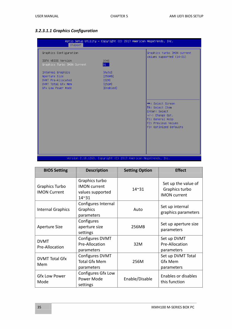
3.2.3.1.1 Graphics Configuration
BIOS Setting Description Setting Option Effect
Graphics Turbo IMON Current
Graphics turbo IMON current values supported 14~31
14~31 Set up the value of
Graphics turbo IMON current
Internal Graphics Configures Internal Graphics parameters
Auto Set up internal graphics parameters
Aperture Size Configures aperture size settings
256MB Set up aperture size parameters
DVMT Pre-Allocation
Configures DVMT Pre-Allocation parameters
32M Set up DVMT Pre-Allocation parameters
DVMT Total Gfx Mem
Configures DVMT Total Gfx Mem parameters
256M Set up DVMT Total Gfx Mem parameters
Gfx Low Power Mode
Configures Gfx Low Power Mode settings
Enable/Disable Enables or disables this function

USER MANUAL CHAPTER 3 AMI UEFI BIOS SETUP
IKMH100 M-SERIES BOX PC 36
3.2.3.2 PCI Configuration
BIOS Setting Description Setting Option Effect
PCI Express Configuration
Configures PCI Express parameters
Enter Opens submenu
USB Configuration Configures USB parameters
Enter Opens submenu
PCH LAN Controller Configures PCH LAN Controller parameters
Enable/Disable Enables or disables this function
Wake on LAN Set up wake on LAN function
Enable/Disable Enables or disables this function
SLP_A4 Assertion Width
Configures SLP_A4 Assertion Width parameters
4-5 seconds Set up SLP_A4 Assertion Width parameters
Restore AC Power Loss
Enabling this will allow the computer to power up once house hold power is established.
Power On Set Restore AC Power Loss parameters
USER MANUAL CHAPTER 5 AMI UEFI BIOS SETUP
37 IKMH100 M-SERIES BOX PC
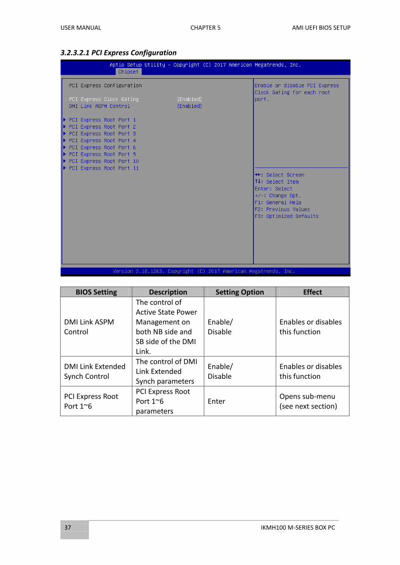
3.2.3.2.1 PCI Express Configuration
BIOS Setting Description Setting Option Effect
DMI Link ASPM Control
The control of Active State Power Management on both NB side and SB side of the DMI Link.
Enable/ Disable
Enables or disables this function
DMI Link Extended Synch Control
The control of DMI Link Extended Synch parameters
Enable/ Disable
Enables or disables this function
PCI Express Root Port 1~6
PCI Express Root Port 1~6 parameters
Enter Opens sub-menu (see next section)

USER MANUAL CHAPTER 3 AMI UEFI BIOS SETUP
IKMH100 M-SERIES BOX PC 38
PCI Express Root
BIOS Setting Description Setting Option Effect
PCI Express Root Port 1
The control of PCI Express Root Port
Enable/ Disable
Enables or disables this function
ASPM Support Configures ASPM Support parameters
Enable/ Disable
Enables or disables this function
L1 Substates Configures L1 Substates parameters
L1.1 & L1.2 Setting up L1 Substates parameters
Gen3 Eq Phase3 Method
Configures Gen3 Eq Phase3 Method
Software Search Setting up Gen3 Eq Phase3 Method parameters
PCI Speed Configures PCI Speed parameters
Auto Setting up PCI Speed
Detect Non-Compliance Device
Detect the device that is not compliant to the system settings
Enable/ Disable
Enables or disables this function
Extra Bus Reserved Configures Extra Bus Reserved parameters
Set the value Setting up the value

USER MANUAL CHAPTER 5 AMI UEFI BIOS SETUP
39 IKMH100 M-SERIES BOX PC
Reserved Memory Configures Reserved Memory parameters
Set the value Setting up the value
Prefetchable Memory
Configures Prefetchable Memory parameters
Set the value Setting up the value
USB Configuration
BIOS Setting Description Setting Option Effect
USB Precondition Allows user to enable or disable USB Precondition
Enable/ Disable
Enables or disables this function
USB Ports Per-Port Disable Control
Control each of the USB ports (0~XX) disabling
Enable/ Disable
Enables or disables this function

USER MANUAL CHAPTER 3 AMI UEFI BIOS SETUP
IKMH100 M-SERIES BOX PC 40
3.2.4 Security Menu
This section allows you to configure and improve your system and allows you to set up some system features according to your preference.
BIOS Setting Description Setting Option Effect
Administrator Password
Displays whether or not an administrator password has been set.
Enter Enter password
User Password Display whether or not a user Password has been set.
Enter Enter password
Secure Boot Menu This feature designed to prevent malicious software and unauthorized media from loading during the boot process.
Enter Opens sub-menu

USER MANUAL CHAPTER 5 AMI UEFI BIOS SETUP
41 IKMH100 M-SERIES BOX PC
3.2.4.1 Security Boot Menu
BIOS Setting Description Setting Option Effect
Secure Boot Secure Boot is a feature designed to prevent malicious software and unauthorized media from loading during the boot process.
Enable/ Disable
Enables or disables this function
Secure Boot Management
Manage Secure Boot settings
Custom
Configure Secure Boot parameters
Key Management Setting Key Management parameters
Enter Opens sub-menu

USER MANUAL CHAPTER 3 AMI UEFI BIOS SETUP
IKMH100 M-SERIES BOX PC 42
Key Management
USER MANUAL CHAPTER 5 AMI UEFI BIOS SETUP
43 IKMH100 M-SERIES BOX PC
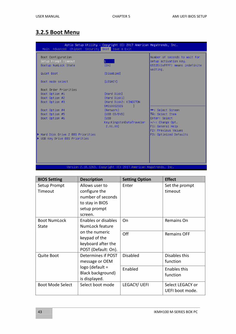
3.2.5 Boot Menu
BIOS Setting Description Setting Option Effect
Setup Prompt Timeout
Allows user to configure the number of seconds to stay in BIOS setup prompt screen.
Enter Set the prompt timeout
Boot NumLock State
Enables or disables NumLock feature on the numeric keypad of the keyboard after the POST (Default: On).
On Remains On
Off Remains OFF
Quite Boot Determines if POST message or OEM logo (default = Black background) is displayed.
Disabled Disables this function
Enabled Enables this function
Boot Mode Select Select boot mode LEGACY/ UEFI Select LEGACY or UEFI boot mode.

USER MANUAL CHAPTER 3 AMI UEFI BIOS SETUP
IKMH100 M-SERIES BOX PC 44
Boot Option Priorities
Specifies the overall boot order from the available devices
Ex: Boot Option#1 (network); Options: #1~#7
Ex.: Set Network as the first priority
Hard Drive 2 BBS Priorities
Specifies the boot order for Hard Drive BBS parameters
Enter Enter the submenu
USB Key Drive Priorities
Specifies the boot order for USB Key Drive
Enter Enter the submenu

USER MANUAL CHAPTER 5 AMI UEFI BIOS SETUP
45 IKMH100 M-SERIES BOX PC
3.2.6 Save&Exit
BIOS Setting Description Setting Option Effect
Save Changes and Exit
This saves the changes to the CMOS and exits the BIOS Setup program.
<YES> Save changes
Discard Changes and Exit
This exits the BIOS Setup without saving the changes made in BIOS Setup to the CMOS.
<YES> Saves the changes
<NO> Return to the BIOS Setup Main Menu
Save Changes and Reset
Reset the system after saving the changes.
<YES> Saves the changes
<NO> Return to the BIOS Setup Main Menu
Discard Changes and Reset
Reset system setup without saving any changes
<YES> Saves the changes
<NO> Return to the BIOS Setup Main Menu
Save Changes Save changes done so far to any of the
<YES> Saves the changes

USER MANUAL CHAPTER 3 AMI UEFI BIOS SETUP
IKMH100 M-SERIES BOX PC 46
setup options. <NO> Return to the BIOS Setup Main Menu
Discard Changes Discard changes done so far to any of the setup options.
<YES> Saves the changes
<NO> Return to the BIOS Setup Main Menu
Restore Defaults Restore/load default values for all the setup options.
<YES> Saves the changes
<NO> Return to the BIOS Setup Main Menu
Save as User Defaults
Save the changes done so far as User defaults.
<YES> Saves the changes
<NO> Return to the BIOS Setup Main Menu
Restore User Defaults
Restore the User Defaults to all the setup options.
<YES> Saves the changes
<NO> Return to the BIOS Setup Main Menu
Launch EFI Shell Launch Extensible Firmware Interface menu
<YES> Saves the changes
<NO> Return to the BIOS Setup Main Menu

USER MANUAL CHAPTER 5 AMI UEFI BIOS SETUP
47 IKMH100 M-SERIES BOX PC
3.3 Using Recovery Wizard to Restore Computer
Note:
Before starting the recovery process, make sure to backup all user data.
The data will be lost after the recovery process.
To enable quick one-key recovery procedure:
Plug-in the AC adapter to the series computer. Make sure the computer stays plugged in
to power source during the recovery process.
Turn on the computer, and when the boot screen shows up, press the F6 to initiate the
Recovery Wizard.
The following screen shows the Recovery Wizard. Click Recovery button to continue.
USER MANUAL CHAPTER 3 AMI UEFI BIOS SETUP
IKMH100 M-SERIES BOX PC 48
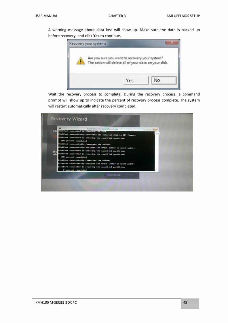
A warning message about data loss will show up. Make sure the data is backed up
before recovery, and click Yes to continue.
Wait the recovery process to complete. During the recovery process, a command
prompt will show up to indicate the percent of recovery process complete. The system
will restart automatically after recovery completed.

USER MANUAL CHAPTER 3 AMI UEFI BIOS SETUP
49 IKMH100 M-SERIES BOX PC
3.4 How to Enable Watchdog
To enable Watchdog, you need to download Winmate Watchdog utility. Find more
information on Watchdog in “Watchdog Guide” that you can download from
Winmate Download Center or File Share. Refer to the User Manual for more details.
To enable watchdog in Watchdog AP follow the instructions below:
1. On the right bottom side of the desktop screen, click triangle button to
show hidden icons.
2. Click icon to open Watchdog utility.

USER MANUAL CHAPTER 3 AMI UEFI BIOS SETUP
IKMH100 M-SERIES BOX PC 50
3. In Watchdog utility window set countdown time and periodically feed time,
or disable watchdog.
Example:
Every 10 min watchdog will monitor
the system, in case any error occurs
the system will restart automatically
when the countdown time reaches 0.
Every 9 min watchdog timer will be
reset to 10 min.
Setting Description
Watchdog Countdown Time
The system automaticity restarts when
this countdown time reaches zero.
Default: 10 min
Periodically Feed Time
To set a cycle time to automatically reset
watchdog timer.
Default: 9 min
Enable / Disable
Enable or disable watchdog.
Default: Enable

USER MANUAL CHAPTER 4 DRIVER INSTALLATION
51 IKMH100 M-SERIES BOX PC
DRIVER INSTALLATION This chapter provides driver installation
instructions.
USER MANUAL CHAPTER 4 DRIVER INSTALLATION
IKMH100 M-SERIES BOX PC 52
CHAPTER 4: DRIVER INSTALLATION
This chapter provides instructions on how to install drivers on the IKHM100 M-Series
Box PC.
4.1 Chipset Driver Installation
Follow instructions below to install Chipset driver.
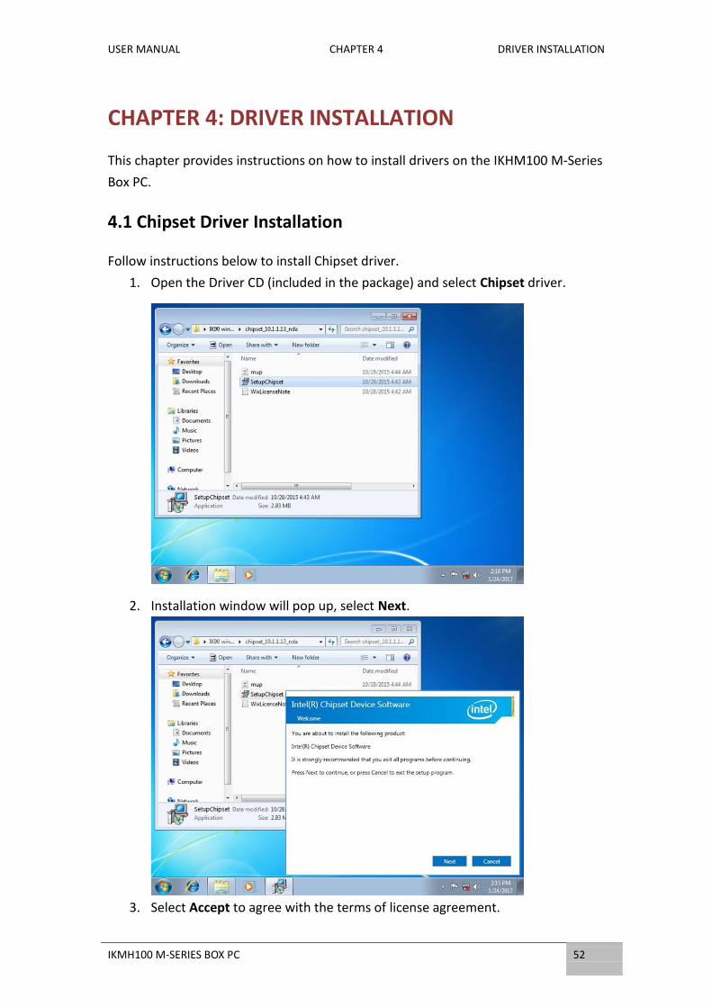
1. Open the Driver CD (included in the package) and select Chipset driver.
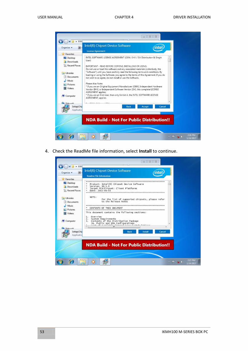
2. Installation window will pop up, select Next.
3. Select Accept to agree with the terms of license agreement.
USER MANUAL CHAPTER 4 DRIVER INSTALLATION
53 IKMH100 M-SERIES BOX PC
4. Check the ReadMe file information, select Install to continue.

USER MANUAL CHAPTER 4 DRIVER INSTALLATION
IKMH100 M-SERIES BOX PC 54
5. Wait for the driver to be installed.
6. When installation completed, select Restart Now to restart your computer.
USER MANUAL CHAPTER 4 DRIVER INSTALLATION
55 IKMH100 M-SERIES BOX PC
4.2 Graphic Driver Installation
Follow instructions below to install Graphic driver.
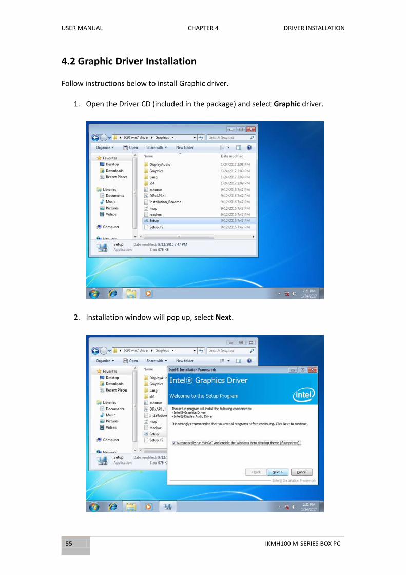
1. Open the Driver CD (included in the package) and select Graphic driver.
2. Installation window will pop up, select Next.
USER MANUAL CHAPTER 4 DRIVER INSTALLATION
IKMH100 M-SERIES BOX PC 56
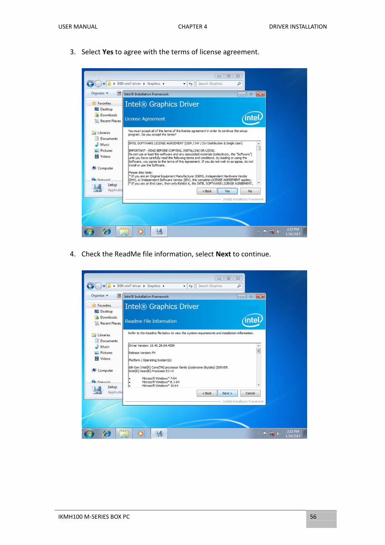
3. Select Yes to agree with the terms of license agreement.
4. Check the ReadMe file information, select Next to continue.
USER MANUAL CHAPTER 4 DRIVER INSTALLATION
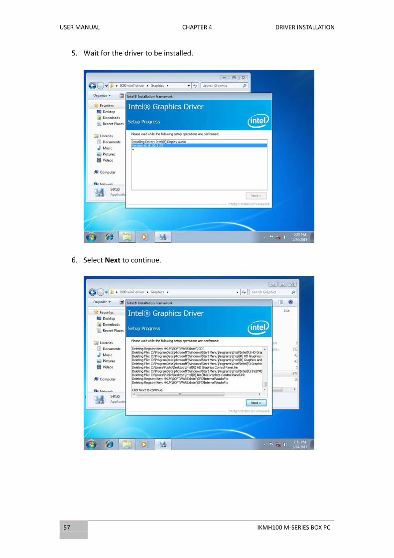
57 IKMH100 M-SERIES BOX PC
5. Wait for the driver to be installed.
6. Select Next to continue.

USER MANUAL CHAPTER 4 DRIVER INSTALLATION
IKMH100 M-SERIES BOX PC 58
7. After installation is completed, select “Yes, I want to restart this computer
now”, and click Finish.

USER MANUAL CHAPTER 4 DRIVER INSTALLATION
59 IKMH100 M-SERIES BOX PC
4.3 ME and NET Framework 1.1 Driver Installation
Follow instructions below to install Management Engine (ME) and .NET Framework
1.1 driver.
1. Open the Driver CD (included in the package) and select ME driver.
2. Error message will pop up, select Finish.

USER MANUAL CHAPTER 4 DRIVER INSTALLATION
IKMH100 M-SERIES BOX PC 60
3. Select .NET Framework 1.1.
4. Select Yes to start the installation.
USER MANUAL CHAPTER 4 DRIVER INSTALLATION
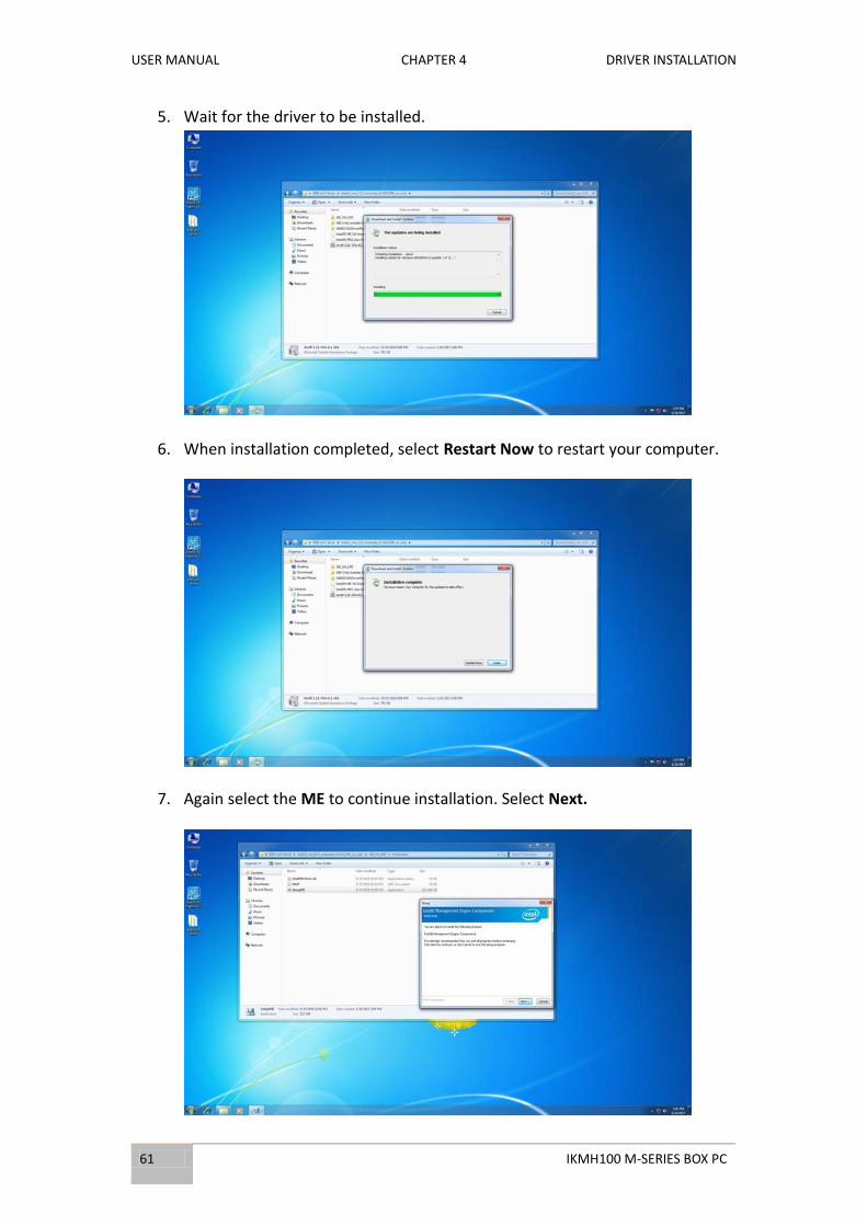
61 IKMH100 M-SERIES BOX PC
5. Wait for the driver to be installed.
6. When installation completed, select Restart Now to restart your computer.
7. Again select the ME to continue installation. Select Next.
USER MANUAL CHAPTER 4 DRIVER INSTALLATION
IKMH100 M-SERIES BOX PC 62
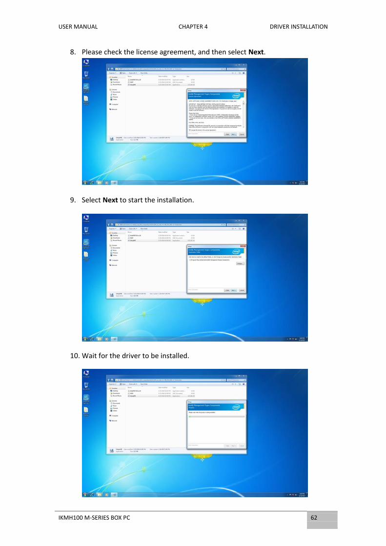
8. Please check the license agreement, and then select Next.
9. Select Next to start the installation.
10. Wait for the driver to be installed.
USER MANUAL CHAPTER 4 DRIVER INSTALLATION
63 IKMH100 M-SERIES BOX PC
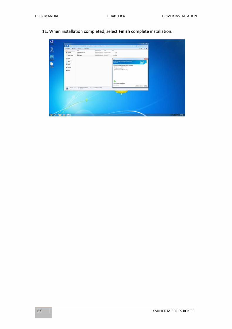
11. When installation completed, select Finish complete installation.

USER MANUAL CHAPTER 4 DRIVER INSTALLATION
IKMH100 M-SERIES BOX PC 64
4.4 Audio Driver Installation
Follow instructions below to install Audio driver.
1. Open the Driver CD (included in the package) and select Audio driver.
2. Select Next to continue.

USER MANUAL CHAPTER 4 DRIVER INSTALLATION
65 IKMH100 M-SERIES BOX PC
3. Wait for the driver to be installed.
4. When installation completed, select Finish complete installation.

USER MANUAL CHAPTER 4 DRIVER INSTALLATION
IKMH100 M-SERIES BOX PC 66
4.5 LAN Driver Installation
Follow instructions below to install LAN driver.
1. Open the Driver CD (included in the package) and select LAN driver.
2. Compression has started.

USER MANUAL CHAPTER 4 DRIVER INSTALLATION
67 IKMH100 M-SERIES BOX PC
3. When compression is complete, select Next.
4. Read the license agreement, and then select Next.
5. System displays the installed packages, select Next.
USER MANUAL CHAPTER 4 DRIVER INSTALLATION
IKMH100 M-SERIES BOX PC 68
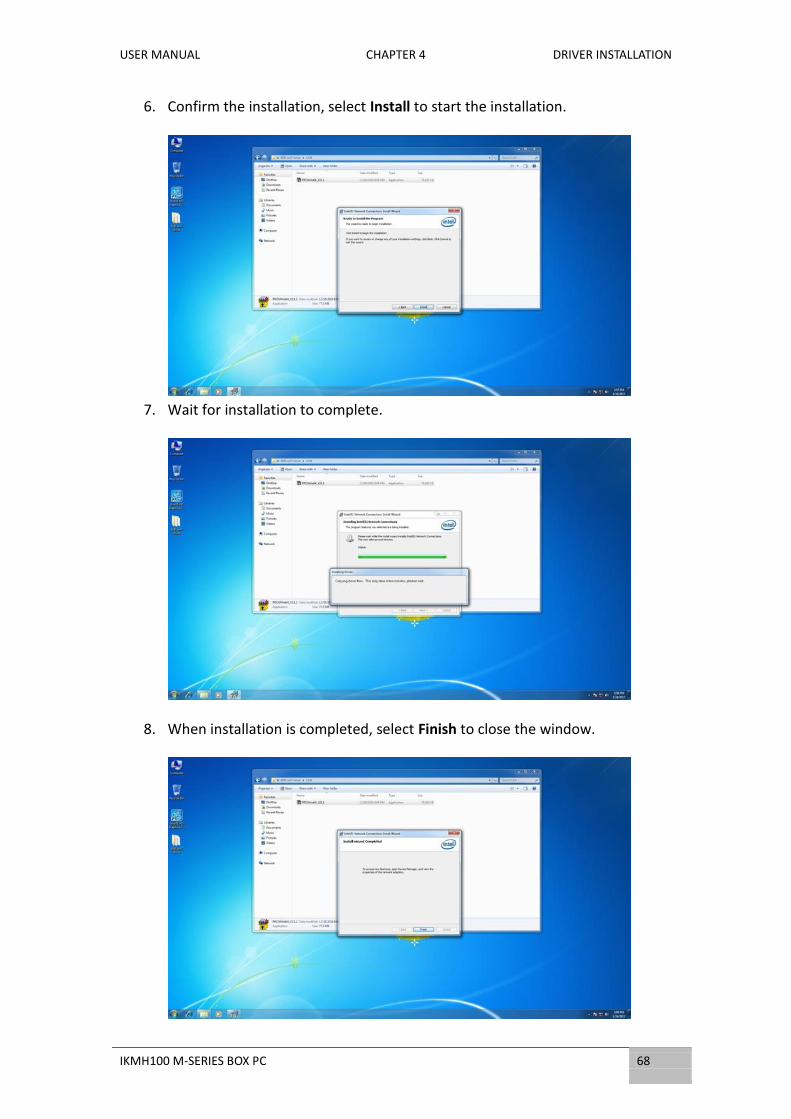
6. Confirm the installation, select Install to start the installation.
7. Wait for installation to complete.
8. When installation is completed, select Finish to close the window.

USER MANUAL CHAPTER 4 DRIVER INSTALLATION
69 IKMH100 M-SERIES BOX PC
4.6 RST Driver Installation
Follow instructions below to install RTS driver.
1. Open the Driver CD (included in the package) and select RTS driver.
2. Select Next to continue.
USER MANUAL CHAPTER 4 DRIVER INSTALLATION
IKMH100 M-SERIES BOX PC 70
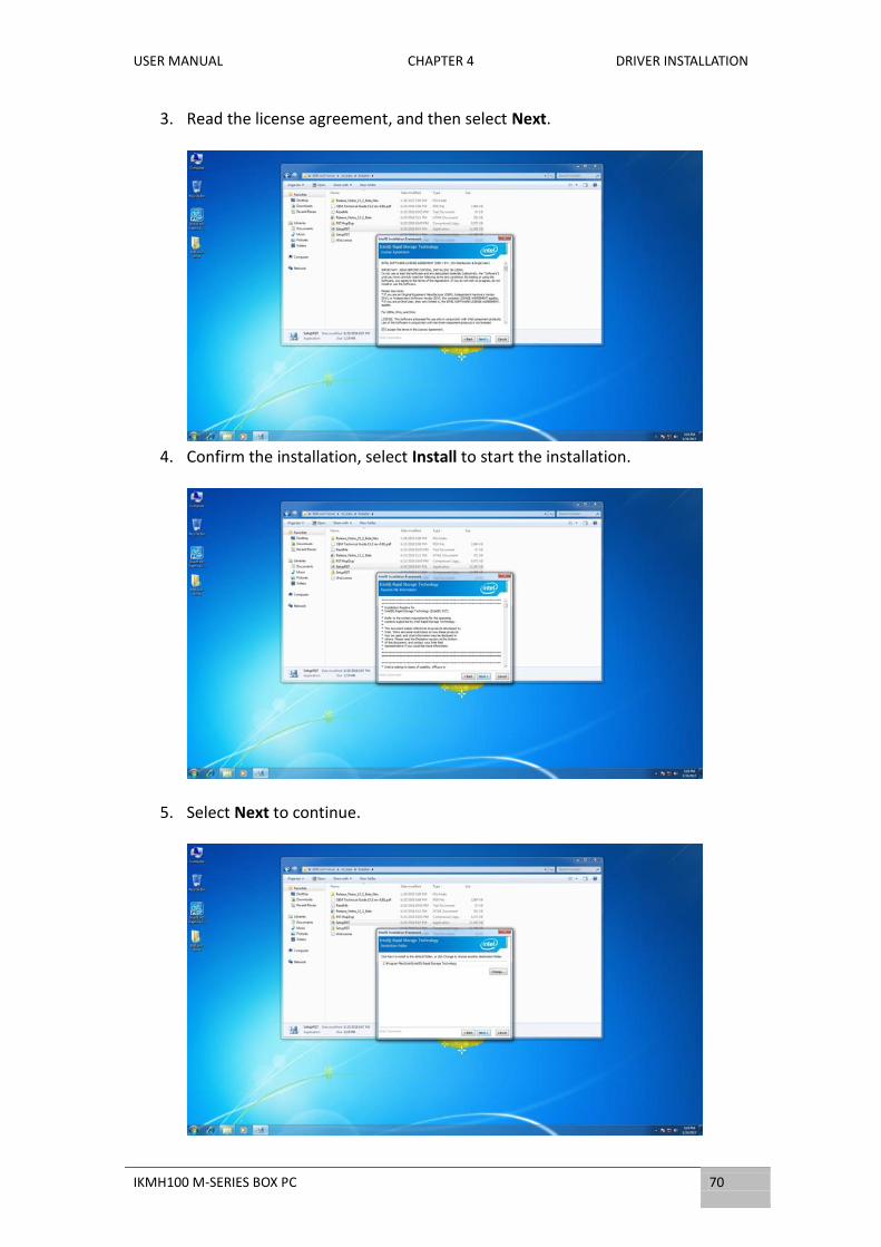
3. Read the license agreement, and then select Next.
4. Confirm the installation, select Install to start the installation.
5. Select Next to continue.

USER MANUAL CHAPTER 4 DRIVER INSTALLATION
71 IKMH100 M-SERIES BOX PC
6. Select Next to start the installation.
7. Wait for installation to complete.
8. Warning message will pop up, select Install.

USER MANUAL CHAPTER 4 DRIVER INSTALLATION
IKMH100 M-SERIES BOX PC 72
9. Installation continues.
10. When installation is completed, select Finish to close the window.
USER MANUAL CHAPTER 4 DRIVER INSTALLATION
73 IKMH100 M-SERIES BOX PC
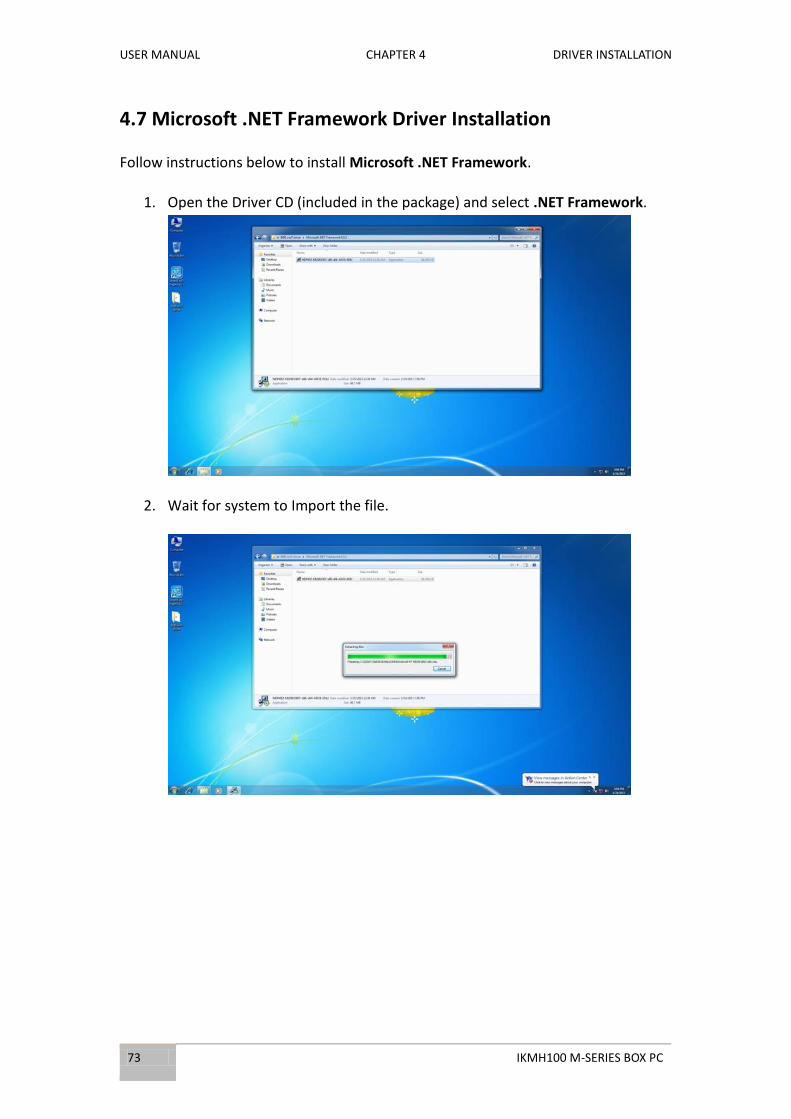
4.7 Microsoft .NET Framework Driver Installation
Follow instructions below to install Microsoft .NET Framework.
1. Open the Driver CD (included in the package) and select .NET Framework.
2. Wait for system to Import the file.

USER MANUAL CHAPTER 4 DRIVER INSTALLATION
IKMH100 M-SERIES BOX PC 74
3. Read the license agreement, and then select “I agree”.
4. Wait for installation to complete.
5. When installation is completed, select Finish to close the window.

USER MANUAL CHAPTER 4 DRIVER INSTALLATION
75 IKMH100 M-SERIES BOX PC
4.8 WatchDog Driver Installation
For more details about Winmate Watchdog, please download Watchdog Guide from
Winmate Downloads Center:
http://dc.winmate.com.tw/_downloadCenter/2017/Embedded%20Computing/Watc
hdog%20Guide_IB_IH_IV_IK.pdf
Follow instructions below to install Watchdog driver.
1. Open the Driver CD (included in the package) and select Watchdog driver.
2. Check message and select Install to begin the installation.

USER MANUAL CHAPTER 4 DRIVER INSTALLATION
IKMH100 M-SERIES BOX PC 76
3. Wait for installation to complete.
4. When installation is complete, press any key to close.
5. Open the Driver CD (included in the package) and select Watchdog AP.
USER MANUAL CHAPTER 4 DRIVER INSTALLATION
77 IKMH100 M-SERIES BOX PC
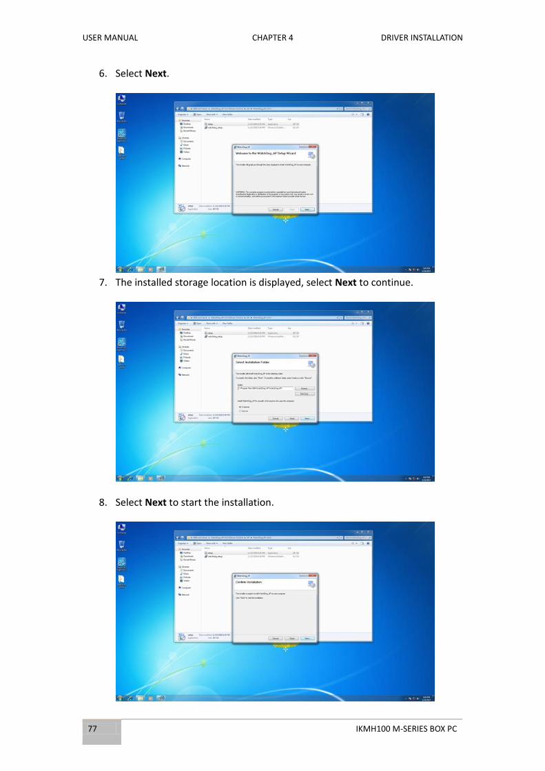
6. Select Next.
7. The installed storage location is displayed, select Next to continue.
8. Select Next to start the installation.
USER MANUAL CHAPTER 4 DRIVER INSTALLATION
IKMH100 M-SERIES BOX PC 78
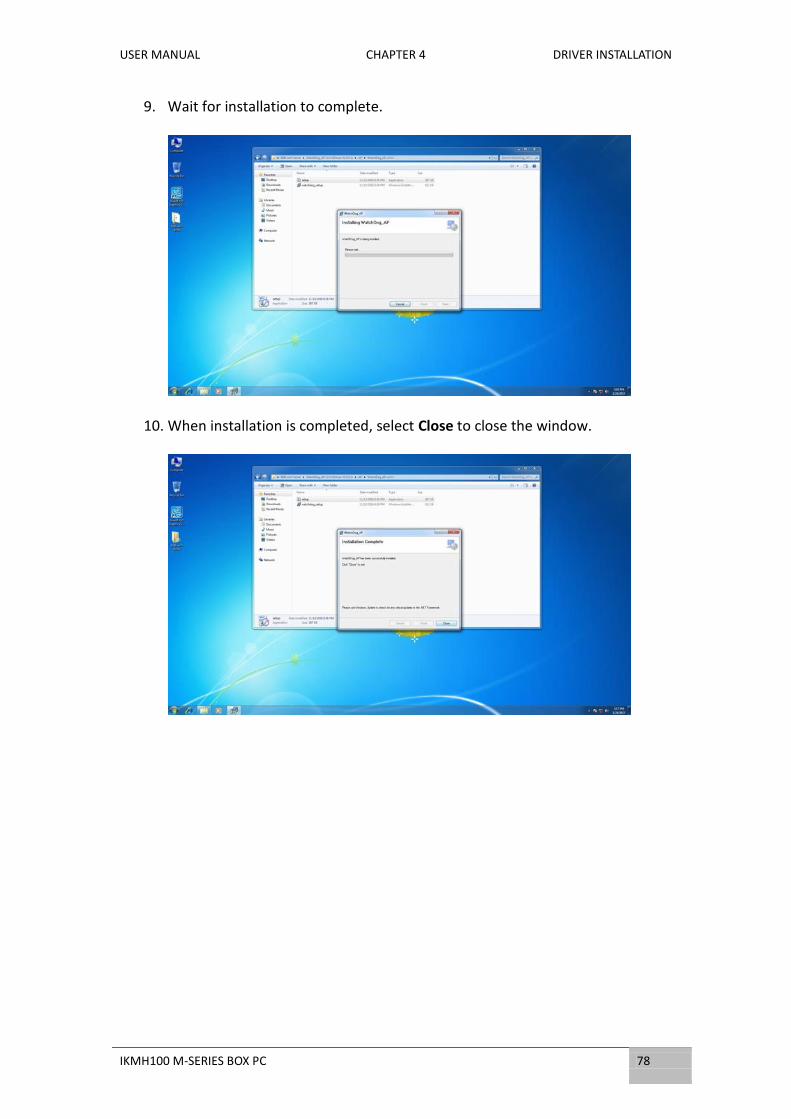
9. Wait for installation to complete.
10. When installation is completed, select Close to close the window.

USER MANUAL CHAPTER 5 TECHNICAL SUPPORT
79 IKMH100 M-SERIES BOX PC
TECHNICAL SUPPORT This chapter contains directory to technical
support.

USER MANUAL CHAPTER 5 TECHNICAL SUPPORT
IKMH100 M-SERIES BOX PC 80
CHAPTER 5: TECHNICAL SUPPORT
This chapter includes technical support documents and software developing kit (SDK).
If any problem occurs fill in problem report form enclosed and immediately contact
us.
5.1 Software Developer Support
Winmate provides the following development kits (SDK) for IKMH100 M-Series Box
PC:
Item File Type Description
1 Watchdog SDK & AP Watchdog SDK and AP
You can download drivers and SDK and other from Winmate Download Center or
Winmate File Share.
Winmate Download Center:
http://www.winmate.com/DownCenter/DownLoadCenter.asp?DownType=2906&Onl
yContent
Winmate File Share: https://winmate.box.com/v/M-Series-Box-PC-IKMH100

USER MANUAL CHAPTER 5 TECHNICAL SUPPORT
81 IKMH100 M-SERIES BOX PC
5.2 Problem Report Form
M-Series Box PC (Modular Design)
Customer name:
Company:
Tel.: Fax:
E-mail: Date:
Product Serial Number:
____________________________________________________________________
Problem Description: Please describe the problem as clearly as possible. Detailed
description of the occurred problem will allow us to find the best solution to solve
the problem as soon as possible.
_____________________________________________________________________
_____________________________________________________________________
_____________________________________________________________________
_____________________________________________________________________
_____________________________________________________________________
_____________________________________________________________________
_____________________________________________________________________
_____________________________________________________________________
_____________________________________________________________________
_____________________________________________________________________
_____________________________________________________________________
_____________________________________________________________________
_____________________________________________________________________
_____________________________________________________________________
_____________________________________________________________________
_____________________________________________________________________
_____________________________________________________________________
_____________________________________________________________________

USER MANUAL APPENDIX A PCIE CARD DIMENSIONS
IKMH100 M-SERIES BOX PC 82
PCIE CARD DIMENSIONS
This section includes mechanical
dimensions of Expansion PCIe Card
Appendix
USER MANUAL APPENDIX A PCIE CARD DIMENSIONS
83 IKMH100 M-SERIES BOX PC
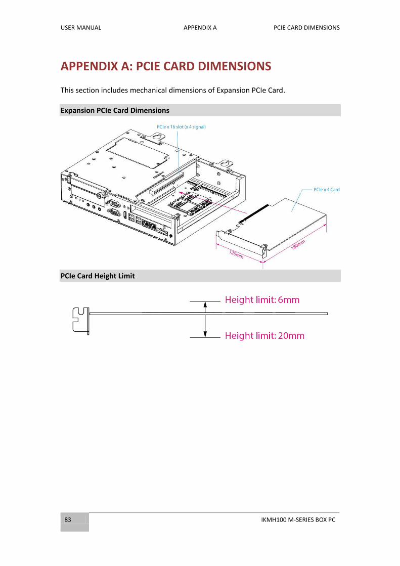
APPENDIX A: PCIE CARD DIMENSIONS
This section includes mechanical dimensions of Expansion PCIe Card.
Expansion PCIe Card Dimensions
PCIe Card Height Limit

USER MANUAL APPENDIX B PRODUCT SPECIFICATIONS
IKMH100 M-SERIES BOX PC 84
PRODUCT SPECIFICATIONS
This section includes IKMH100
technical specifications.
Appendix
USER MANUAL APPENDIX B PRODUCT SPECIFICATIONS
85 IKMH100 M-SERIES BOX PC
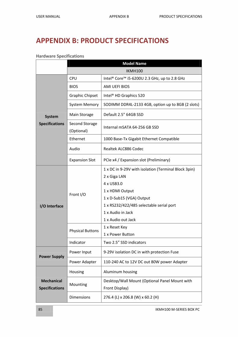
APPENDIX B: PRODUCT SPECIFICATIONS
Hardware Specifications
Model Name
IKMH100
System
Specifications
CPU Intel® Core™ i5-6200U 2.3 GHz, up to 2.8 GHz
BIOS AMI UEFI BIOS
Graphic Chipset Intel® HD Graphics 520
System Memory SODIMM DDR4L-2133 4GB, option up to 8GB (2 slots)
Main Storage Default 2.5" 64GB SSD
Second Storage
(Optional) Internal mSATA 64-256 GB SSD
Ethernet 1000 Base-Tx Gigabit Ethernet Compatible
Audio Realtek ALC886 Codec
Expansion Slot PCIe x4 / Expansion slot (Preliminary)
I/O Interface
Front I/O
1 x DC in 9-29V with isolation (Terminal Block 3pin)
2 x Giga LAN
4 x USB3.0
1 x HDMI Output
1 x D-Sub15 (VGA) Output
1 x RS232/422/485 selectable serial port
1 x Audio in Jack
1 x Audio out Jack
Physical Buttons 1 x Reset Key
1 x Power Button
Indicator Two 2.5” SSD indicators
Power Supply Power Input 9-29V isolation DC in with protection Fuse
Power Adapter 110-240 AC to 12V DC out 80W power Adapter
Mechanical
Specifications
Housing Aluminum housing
Mounting Desktop/Wall Mount (Optional Panel Mount with
Front Display)
Dimensions 276.4 (L) x 206.8 (W) x 60.2 (H)

USER MANUAL APPENDIX B PRODUCT SPECIFICATIONS
IKMH100 M-SERIES BOX PC 86
Environmental
Specifications
Operating
Temp. 0°C~+50°C
Operating
Humidity 30%-95% at 40 (non-condensing, RH)
Optional
Operating
System
Operating
System
Windows 10 IoT Enterprise
Windows Embedded 8 Standard
Windows Embedded Standard 7

Winmate Inc.
9F, No.111-6, Shing-De Rd., San-Chung District,
New Taipei City 24158, Taiwan, R.O.C
Tel: 886-2-8511-0288
Fax: 886-2-8511-0211
Email: [email protected]
Official website: www.winmate.com