Embed Size (px)
Citation preview
M-SERIES
Specifications are subject to change without notice. © 2016 Mitsubishi Electric US, Inc.
Job Name:
System Reference: Date:
SUBMITTAL DATA: MSZ-HM24NA-U1 & MUZ-HM24NA2-U1 24,000 BTU/H WALL-MOUNTED HEAT PUMP SYSTEM
Indoor Unit: MSZ-HM24NA-U1
Outdoor Unit: MUZ-HM24NA2-U1Wireless Remote Controller
ACCESSORIES:Indoor Unit
□ Condensate Pump (BlueDiamond X87-711/721; 115/230V) □ Condensate Pump (Sauermann SI30-115/230; 115/230V) □ Anti-Allergy Enzyme Filter (MAC-408FT-E) □ Drain Pan Level Sensor (DPLS2)
Outdoor Unit
□ Outdoor Mounting Pad (ULTRILITE1) □ Drain Pan Heater (MAC-642BH-U) □ 3-1/4” Mounting Base [Pair] (DSD-400P) □ Drain Pan Socket (MAC-851DS) □ Air Outlet Guide (MAC-886SG-E) □ Wall Mounting Bracket (QSWB2000M-1)
SPECIFICATIONS:
Rated Conditions (Capacity / Input)
Cooling1 Btu/h / W 22,500 / 2,630
Heating at 47º F2 Btu/h / W 26,000 / 2,500
Capacity Range Minimum Maximum
Cooling1 Btu/h 5,800 22,500
Heating at 47º F2 Btu/h 5,400 26,000
Heating at 17º F3 Btu/h - 18,500
Heating at 5º F4 Btu/h - 15,0001 Cooling | Indoor: 80º F(27º C)DB / 67º F(19º C)WB; Outdoor: 95º F(35º C)DB / 75º F(24º C)WB* 2 Heating at 47ºF | Indoor: 70º F (21º C)DB / 60º F (16º C)WB; Outdoor: 47º F (8º C)DB / 43º F (6º C)WB* 3 Heating at 17º F | Indoor: 70º F(21º C)DB / 60º F(16º C)WB; Outdoor: 17º F(-8º C)DB / 15º F(-9º C)WB* 4 Heating at 5º F | Indoor: 70º F (21º C)DB / 60º F(16º C)WB; Outdoor: 5º F(-15º C) DB / 5º F(-15º C)WB * Rating Conditions per AHRI Standard:
Operating Conditons (Indoor Intake Air Temp.) (Max./ Min.)
Cooling 90º F (32º C) DB / 67º F (19º C) DB
Heating 80º F (27º C) DB / 70º F (21º C) DB
Operating Conditons (Outdoor Intake Air Temp.) (Max./ Min.)
Cooling5 115 F (46º C) DB / 14º F (-10º C) DB
Heating 75º F (24º C) DB / 5º F (-15º C) DB**
5 Applications should be restricted to comfort cooling only; equipment cooling applications are not recommended for low ambient temperature conditions.** System cuts out at -9º F (-27º C) to avoid thermistor error and automatically restarts at -4º F (-20º C).
AHRI Efficiency Ratings
SEER / HSPF 18.0 / 8.5
COP at 47o F / 17o F 3.05 / 2.36
Electrical Power Requirements 208 / 230V, 1-Phase, 60 Hz
Minimum Circuit Ampacity (MCA)
Indoor / Outdoor A 1 / 14
Indoor Unit
Blower Motor (ECM) F.L.A. 0.67
Blower Motor Output W 30
SHF / Moisture Removal 0.87 / 2.3 pt./h
Field Drainpipe Size O.D. In.(mm) 5/8 (15)
Outdoor Unit
Compressor DC INVERTER-driven Twin Rotary
Fan Motor (ECM) F.L.A. 0.93
Airflow Rate (Lo - Med - Hi - Super Hi)
Indoor (Cooling)
DRY
CFM
353-431-530-702
WET 318-388-477-632
Indoor (Heating) DRY 346-448-579-702
Outdoor 1,691 / 1,691
Sound Pressure Level (Lo - Med - Hi - Super Hi)
IndoorCooling
dB(A)
33-38-44-50
Heating 32-38-44-50
OutdoorCooling 54
Heating 55
External Dimensions
Indoor (H x W x D)
In.(mm)
12 x 36-5/16 x 9-13/16 (305 x 923 x 250)
Outdoor (H x W x D) 34-5/8 x 33-1/16 x 13 (880 x 840 x 330)
Net Weight
IndoorLbs.(kg)
28 (13)
Outdoor 121 (55)
External Finish
Indoor Munsell 1.0Y 9.2 / 0.2
Outdoor Munsell No. 3Y 7.8 / 1.1
Refrigerant R410A; 3 lb. 9 oz.
Refrigerant Piping (Flared)
Liquid (High Pressure)In.(mm)
3/8 (9.52)
Gas (Low Pressure) 5/8 (15.88)
Max. Total Refrigerant Pipe Length (Height Diff.)
Ft. (m)
50 (15)
Max. Total Refrigerant Pipe Length (Length.) 100 (30)
Specifications are subject to change without notice. © 2016 Mitsubishi Electric US, Inc.
1340 Satellite Boulevard. Suwanee, GA 30024Toll Free: 800-433-4822 www.mehvac.com
FORM# MSZ-HM24NA-U1 / MUZ-HM24NA2-U1 - 201603
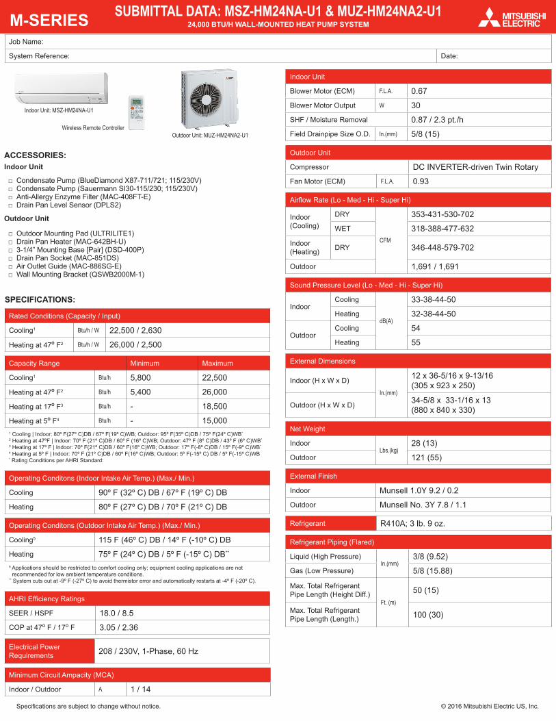
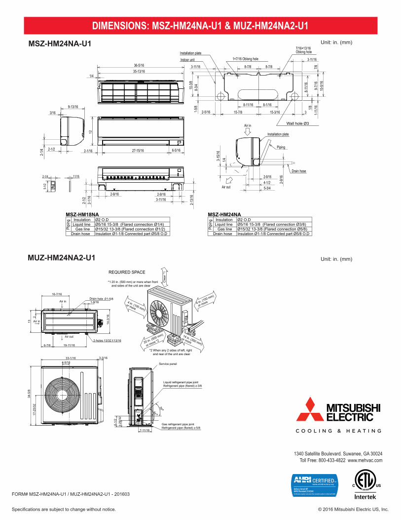
DIMENSIONS: MSZ-HM24NA-U1 & MUZ-HM24NA2-U1MSZ-HM24NA-U1
MUZ-HM24NA2-U1
Unit: in. (mm)
10
MUZ-HM24NA MUZ-HM24NA2 Unit: inch
16-7/16
1-9/161-5/8Drain hole
6-7/8 19-11/16
13
2
Air in
Air in
Air out2-holes 13/32 13/16
14-3
/16
33-1/164-5/16
3-3/16
34-5
/8
17-2
5/32
Service panel
3-29
/32
6-1/
2
7-11/16
35
44
Liquid refrigerant pipe jointRefrigerant pipe (flared) Ø 3/8
Gas refrigerant pipe jointRefrigerant pipe (flared) Ø 5/8
*1 20 in. (500 mm) or more when front and sides of the unit are clear
14 in. (350 mm)
or more
4 in. (100 mm)
or more
REQUIRED SPACE
Cle
ar *
1
4 in. (100 mm)
or more
20 in. (500 mm)
or more *2
*2 When any 2 sides of left, right and rear of the unit are clear
OBH747A
7
Unit: inchMSZ-HM09NA MSZ-HM12NA MSZ-HM15NA
MSZ-HM18NA MSZ-HM24NA
4 OUTLINES AND DIMENSIONS
Pipi
ng InsulationMSZ-HM24NA
Ø2 O.DLiquid line Ø5/16 15-3/8 (Flared connection Ø3/8)
Gas line Ø15/32 13-3/8 (Flared connection Ø5/8)Drain hose Insulation Ø1-1/8 Connected part Ø5/8 O.D
Pipi
ng InsulationMSZ-HM18NA
Ø2 O.DLiquid line Ø5/16 15-3/8 (Flared connection Ø1/4)
Gas line Ø15/32 13-3/8 (Flared connection Ø1/2)Drain hose Insulation Ø1-1/8 Connected part Ø5/8 O.D
11/16
5-1/2
2-1/4
2-1/4 2-1/2
9-13/163/16
35-13/1636-5/16
1/4
27-15/16 6-5/162-1/16
12
2-9/162-
13/16
2-1/2
2-9/163-11/16
2-1/1
6
9-7/1
610
-5/16
1/8
8-7/8 8-7/83-11/16
8-3/410
-3/8
2-5/16 15-7/8
8-11/16
3-11/16
7/8
1×7/16 Oblong hole
7/16×13/16Oblong holeInstallation plate
Indoor unit
Wall hole Ø3Air in
Installation plate
8-1/16
15-3/161-5/8
8-11
/16
3 1-11
/16
2-9/16
2-9/1
6
4-1/25-3/4
1/4
Air out
Piping
Drain hose
3-15
/16
11/16
5-1/2
2-1/4
Pip
ing
Insulation ø1 - 3/8 O.DLiquid line ø1/4 19 - 11/16 (Flared connection ø1/4)Gas line ø3/8 16 - 15/16
(Flared connection: ø3/8 (HM09/12NA), ø1/2 (HM15NA))Drain hose Insulation ø1-1/8 O.D Connected part ø5/8 O.D
OBH746AUnit: in. (mm)