Embed Size (px)
Citation preview

m Pure Class A operation delivers quality power: 60 watts × 2 into 8 ohms m Power MOS-FET output stage features 10-parallel push-pull confi guration and delivers linear high power progression to ultra-low 1-ohm impedances m Input section confi gured as instrumentation amplifi er m Further improved MCS+ circuit in amplifi er section m Current feedback topology combines stable operation with outstanding sound m Bridged mode allows upgrading to monophonic amplifi er m Two selectable meter types: digital power meters showing true power values and bar graph indicators

547W
365W
214W
118W
61W
5
0
10
15
20
25
0 5 10 15 20 25 30 35
+ B3
- B3
-
++-
+ B1
- B1
- B2
+ B2
Q1
Q3
Q2
Q4Q8
Q6
Q7
Q5 Q9
Q17 Q21
Q19
Q18 Q20
Q22
Q23
Q24
Q25 Q27 Q29 Q31
Q26 Q28 Q30 Q32
Q33
Q34
Q35
Q36
Q37
Q38
Q39
Q40
Q41
Q42
Q13
Q11 Q15
Q10 Q14
Q12 Q16
-+
Power MOS-FETs
n Power modules with 10-parallel push-pull arrangement of power MOS-FETs deliver 480 watts per channel into 1 ohm (music signals), 240 watts into 2 ohms, 120 watts into 4 ohms, or 60 watts into 8 ohms.
n Strong power supply with high-effi ciency toroidal transformer and two extra-large 82,000 μF fi ltering capacitors.
n Bridged mode supports upgrading to monophonic amplifi er with 960 watts into 2 ohms (music signals), 480 watts into 4 ohms, or 240 watts into 8 ohms.
n Instrumentation amplifi er principle allows fully balanced signal paths, and current feedback amplifi er topology drastically improves S/N ratio.
n Four gain control settings (MAX, –3 dB, –6 dB, –12 dB) minimize residual noise.
n Fully balanced input stage shuts out external noise interference.
n Dual mode power meters, switchable to 5-digit numeric readout or 25-point LED bar graph indication.● Meter circuit ON/OFF switch.● Digital power meters show true
output power values, based on output current detected by a Hall element.
● Peak value hold time settings: 1 second, .
n Input selector button (balanced/unbalanced) on front panel.
n Mode selector with dual mono position supports bi-amping.
n Oversize speaker terminals accept also Y lugs.
The combination of pure class A and power MOS-FET devices to realize high output power with excellent sonic purity is a domain where Accuphase excels. Models such as the A-100, A-50V, and A-60 have achieved legendary status among audiophiles and represent an unrivaled level of technological excellence. As a model-change successor to the A-60, the new A-65 incorporates accumulated Ac-cuphase know-how while featuring a number of further im-provements. The input stage is confi gured as an instrumen-tation amplifi er to allow fully balanced input signal paths. The further refi ned MCS+ topology pushes noise and dis-tortion down to absolutely minimal levels, and strictly se-lected materials and parts of the highest quality are used throughout. The end result is a high-end class A stereo am-plifi er with simply stunning performance and sound quality.
The output stage of the A-65 features power MOS-FETs renowned for their excellent sound and superior reliability. For each channel, ten of these devices are arranged in a parallel push-pull arrangement. MOS-FETs have excellent frequency characteristics, and their high input impedance reduces the load imposed on the preceding drive stage. They also have negative thermal characteristics, which ensures perfect operation stability. Driving these devices in pure class A produces rich, high-defi nition sound that brings out the fi nest nuances in the music. In a pure class A amplifi er, the power provided by the power supply is always constant, regardless of the presence of a musical signal. This means that the amplifi er remains unaffected by fl uc-tuations in voltage and other external infl uences.
On the other hand, it also means that the output stage generates considerable thermal energy. In the A-65, this is dissipated effectively by large heat sinks which provide ample capacity to remove the heat pro-duced by the internal circuitry. The high-effi ciency toroidal power transformer housed in an alumi-num diecast enclosure, in conjunction with amply dimensioned smoothing capacitors, provides the muscle to deliver an astonishing 480 watts per channel into a 1-ohm load (music signals only). If even higher power reserves are required, bridged mode turns the A-65 into a superlative mono-phonic power amplifi er.
Pure Class A power amplifi er with power MOS-FET devices — Input stage features ful-
ly balanced signal paths as found in high-quality instrumentation amplifi ers. Further
refi ned MCS+ topology and current feedback result in superb sound quality and out-
standing performance parameters. Strong power supply section and power MOS-FET
devices in ten-parallel push-pull confi guration sustain linear power output progression
down to impedances as low as 1 ohm. Digital power meters show true power readings.
INPUT
Large speaker terminals
Figure 1 Circuit diagram of amplifi er section (one channel)
Hall element
Toroidal power transformer
Bias stabilizer circuit
NFBNETWORK
Mode selectorGain selector
Meter circuitry/control circuitry assembly
Filtering capacitors
Unbalanced and balanced input connectors
NFBNETWORK
GAINCONTROL
Bias stabilizer circuit
Bias stabilizer circuit
Bias stabilizer circuit
NFBNETWORK
REGULATOR
REGULATOR
INPUT
MCS+ (MultipleCircuit Summing)Gain control
Instrumentation amplifi er
10-parallel push-pull power MOS-FET array
Output voltage (V)
Out
put c
urre
nt (A
)
Figure 2 Load impedance vs. output(output voltage/output curr
1-ohm operation pwith music signals
OUTPUT
Bias stabilizer circuit

40 45
+
-
-
+ +
-
+-
-
+
n Power amplifi er assemblyPower amplifier assembly with 10-parallel push-pull power MOS-FET pairs per channel mounted directly to large heat sink, MCS+ circuitry, and current feedback amplifi er.
Instrumentation amplifi er and further refi ned MCS+ topology
Instrumentation amp confi guration allows fully balanced signal paths
The newly adopted “instrumentation amplifi er” principle ensures that all signal paths from the inputs to the power amp stage are fully balanced.
This results in excellent CMRR (Common Mode Rejection Ratio) and minimal distortion. Another signifi cant advantage is the fact that external noise and other external infl uences are virtually shut out. The result is a drastic improvement in operation stability and reliability.
Further refined MCS+ topology for even lower noise
Accuphase’s original MCS (Multiple Circuit Summing) principle uses a number of identical circuits connected in parallel to achieve superior performance characteristics. MCS+ is a further refi ned version of this approach. By extending parallel operation to the class-A drive stage of
the current/voltage converter, the noise fl oor has been lowered further.
t power ent)
ossible s only
Current feedback principle assures excellent phase characteristics in high range
As shown in the illustration, the A-65 uses the output signal current rather than voltage for feedback. Since the impedance at the current feedback point is very low, there is almost no phase shift. A minimal amount of NFB therefore results in maximum improvement of circuit parameters.
INPUT
NFBNETWORK
GAIN CONTROLCIRCUIT
INPUT
NFBNETWORK
Signal input stage Power amplifi er stage
OUTPUT
Instrumentation amplifi er confi guration
INPUT
OUTPUT
INPUT
Current NFB network
I/V converter
Current adder
Trans-impedance amplifi er
Amp-lifi er
Principle of current feedback amplifi er
Buffer
Buffer
RLRL
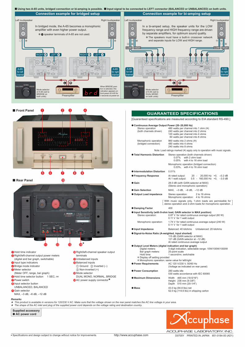
n Front Panel
n Rear Panel
J Right/left-channel speaker output terminals
K Unbalanced inputsL Balanced inputs a Ground b Inverted (–) c Non-inverted (+)M Mode selector DUAL MONO, NORMAL, BRIDGEN AC power supply connector
A Hold time indicatorB Right/left-channel output power meters (digital and bar graph, switchable)C Input type indicatorsD Bridge mode indicatorE Meter selector (Meter OFF, range, bar graph)F Hold time selector button 1 SEC, G Power switchH Input selector button UNBALANCED, BALANCEDI Gain selector MAX, –3 dB, –6 dB, –12 dB
Connection example for bridged setup
Left loudspeaker
GUARANTEED SPECIFICATIONS
Connection example for bi-amping setup
A-65 for left
channel
Right loudspeaker
A-65 for right channel
RIGHT LEFT RIGHT LEFT
Preamplifi er
In bridged mode, the A-65 becomes a monophonic amplifi er with even higher power output.
✽ speaker terminals of A-65 are not used.
Mode selector of A-65 (set to BRIDGE on both units)
When BRIDGE posi-tion is selected, this indication appears on front panel of A-65 for 3 seconds at power-on
A-65 for left
channel
A-65 for right channel
Preamplifi er
In a bi-amped setup, the speaker units for the LOW frequency range and HIGH frequency range are driven by separate amplifi ers, for optimum sound quality.
✽ The speakers must have a built-in crossover network and separate inputs for LOW and HIGH range.
Mode selector of A-65 (set to DUAL MONO on both units)
LOW HIGH LOW HIGH
n Using two A-65 units, bridged connection or bi-amping is possible. n Input signal to be connected to LEFT connector (BALANCED or UNBALANCED) on both units.
Right loudspeakerLeft loudspeaker
[Guaranteed specifi cations are measured according to EIA standard RS-490.]
m Continuous Average Output Power (20–20,000 Hz) Stereo operation 480 watts per channel into 1 ohm ( ) (both channels driven) 240 watts per channel into 2 ohms 120 watts per channel into 4 ohms 60 watts per channel into 8 ohms
Monophonic operation 960 watts into 2 ohms ( ) (bridged connection) 480 watts into 4 ohms 240 watts into 8 ohms
Note: Load ratings marked ( ) apply only to operation with music signals.
m Total Harmonic Distortion Stereo operation (both channels driven) 0.07% with 2 ohm load 0.05% with 4 to 16 ohm load
Monophonic operation (bridged connection) 0.03%, with 4 to 16 ohm load
m Intermodulation Distortion 0.01%
m Frequency Response At rated output: 20 - 20,000 Hz +0, –0.2 dB At 1 watt output: 0.5 - 160,000 Hz +0, –3.0 dB
m Gain 28.0 dB (with GAIN selector at MAX) (Stereo and monophonic operation)
m Gain Selection MAX, –3 dB, –6 dB, –12 dB
m Output Load impedance Stereo operation: 2 to 16 ohms Monophonic operation: 4 to 16 ohms
With music signals only, 1-ohm loads are permissible for stereo operation and 2-ohm loads for monophonic operation.
m Damping Factor 400
m Input Sensitivity (with 8-ohm load, GAIN selector in MAX position) Stereo operation: 0.87 V for rated continuous average output (60 W) 0.11 V for 1 watt output
Monophonic operation: 1.74 V for rated continuous average output (240 W) 0.11 V for 1 watt output
m Input Impedance Balanced: 40 kilohms Unbalanced: 20 kilohms
m Signal-to-Noise Ratio (A-weighted, input shorted) 115 dB (GAIN selector at MAX) 121 dB (GAIN selector at –12 dB) At rated continuous average output
m Output Level Meters (digital indication and bar graph) Digital meters: 5-digit indication, selectable range: 10W/100W/1000W Bar graph meters: 25-point scale Hold time: 1 second/ , switchable
Display off setting provided Monophonic operation: same value for left/right
m Power Requirements AC 120 V/230 V, 50/60 Hz (Voltage as indicated on rear panel)
m Power Consumption 280 watts idle 530 watts accordance with IEC 60065
m Maximum Dimensions Width 465 mm (18-5/16") Height 238 mm (9-3/8") Depth 515 mm (20-1/4")
m Mass 43.0 kg (94.8 lbs) net 52.0 kg (114.6 lbs) in shipping carton
Remarks This product is available in versions for 120/230 V AC. Make sure that the voltage shown on the rear panel matches the AC line voltage in your area. The shape of the AC inlet and plug of the supplied power cord depends on the voltage rating and destination country.
m Specifi cations and design subject to change without notice for improvements. http://www.accuphase.com D0705Y PRINTED IN JAPAN 851-0184-00 (AD1)
Supplied accessory● AC power cord