Embed Size (px)
Citation preview

Buy this product from us and we will include this free PICmicro microcontroller development board (worth £125) with all orders over £800.
FREE
matrix
mmm mmmm
multimedia
[email protected] www.matrixmultimedia.co.uk
PROTEUS CAD SOFTWAREThe Complete Electronics Design SystemThe Complete Electronics Design System
System Features
§
§
§
§
§
§
§
§
§
§
ISIS Schematic Capture - an easy to use yet extremely powerful tool for entering your designs.
PROSPICE Mixed mode SPICE simulation - industry standard SPICE3F5 simulator upgradeable to our unique Virtual System Modelling technology.
ARES PCB Layout - ultra high performance PCB design system with 32 bit database, automatic component placer and rip-up and retry auto-router.
Graphical User Interface standardized across all modules.
All major modules written in house - best possible guarantee of inter-operability and compatibility.
Runs on all 32 bit versions of Windows.
Established, proven product based on more than 12 years of continuous development.
Thousands of installations sold to over 35 countries worldwide.
Technical support direct from the authors.
Rated best overall product in EWW CAD Review Roundup.
PROTEUS combines advanced schematic capture, mixed mode SPICE simulation, PCB layout and auto-routing to make a complete electronics design system.
The system benefits from over 12 years of continuous development, and was rated the best all round product by Electronics World in its comparative review of PCB design systems - “The Route to PCB CAD”.
The PROTEUS product range also includes our revolutionary VSM technology, which allows you to simulate micro-controller based designs, complete with all the surrounding electronics. You can even interact with your design in real time using animated peripheral models for LED/LCD displays, keypads, RS232 terminals and so forth.
Meanwhile our acclaimed auto-placer and auto-routing tools continue to make PCB layout as easy as possible, with the hard work being done by your PC rather than yourself.
downloads available from:www.labcenter.co.ukdownloads available from:www.labcenter.co.uk
Purchase of PROTEUS CAD tools are made on a modular basis. Prices depend on the modules chosen and the number of users. The prices here show the most commonly chosen configurations consisting of:
! Schematic capture system with full PROSPICE mixed mode simulator and libraries.! Virtual System Modelling with PICmicro and ATMEL
microprocessor models and peripheral library.! PCB design package with full autorouter and 1000
pin capacity.
Please contact us for other price combinations
Discounted education prices:
Matrix Multimedia is Labcenter’s authorized Education Support Partner for the UK.
Product Code RRPStarter kit ELPRSK £120
Single User ELPRSI £39210 User ELPR10 £1,17650 User ELPR50 £2,352
50 user PROTEUS and VSM bundle ELPRBUN £5,506

matrix
mmm mmmm
multimedia
www.matrixmultimedia.co.uk
Publication Quality Schematics
Context Sensitive User Interface
Wire Auto-Router
ISIS provides you with full control of the drawing appearance in terms of line widths, fill styles, colours and fonts. This enables you to produce attractive schematics like you see in the magazines rather than the 'thin line' diagrams often associated with older CAD software. Once your drawing is complete you can export it as a graphics file or copy it to the clipboard for incorporation in other documents. This makes ISIS ideal for use in producing technical documentation, academic papers, project reports, as well as being an excellent front end for PCB design.
The drawing appearance is defined in terms of a style template - especially useful if you want to apply a ‘house style’ to all your designs. Furthermore, the scheme allows you to customize the appearance of the library parts supplied with the package.
Much thought has gone into making the most common drawing operations as quick and easy as possible. In particular, ISIS has no wiring mode per se. Instead, you can place a wire at any time by clicking on a component pin or on a previously placed wire. In addition, place, edit, move and delete operations can be achieved directly with the mouse, without having to go through menus or icons. This makes ISIS very quick to use indeed.
Placing a wire can be as simple as clicking on the two pins you want to connect - the Wire Auto-Router does the rest. But if you want a wire in a particular place, you can just click at the intermediate corners. The Wire Auto-Router also operates when components are moved, automatically fixing up the affecting wiring.
ISIS lies right at the heart of the PROTEUS system and is far more than just another schematics package. It combines an exceptionally powerful design environment with the ability to control most aspects of the drawing appearance. Whether your requirement is the rapid entry of complex designs for simulation & PCB layout, or the creation of attractive schematics for publication, ISIS is the tool for the job.
Features
§
§
§
§
§
§
§
§
§
§
§
§
§
Produces high quality schematics like you see in the magazines.
Style templates allow customization of supplied library parts.
Mouse driven, context sensitive user interface.
Automatic wire routing and automatic junction dot placement/removal.
Hierarchical design including parameterization of sub-circuit component values.
Full support for buses including sub-circuit ports and bus pins.
Comprehensive representation for Homogenous and heterogeneous multi-element parts including connectors.
Highly sophisticated management of component properties including customization of the relevant dialog forms.
Large and growing component library of over 6000 parts, most complete with ready to use simulator models.
Netlist formats: Labcenter SDF, SPICE, SPICE-AGE, Tango, Boardmaker, EEDesigner, Futurenet, Racal & Valid.
Electrical Rules Check and Bill of Materials reports.
Output to any Windows printer device in colour or monochrome.
Graphical export in WMF, BMP, DXF, EPS and HPGL formats.
Sc
he
ma
tic
Ca
ptu
reISIS I S I Sntelligent chematic nput ystem

matrix
mmm mmmm
multimedia
www.matrixmultimedia.co.uk
Junction dots are placed and removed automatically. As well as saving time, this avoids ambiguities that might otherwise arise. Manual placement of dots is also allowed, should you prefer to place a dot and then wire to it.
As well as supporting normal multi-sheet designs (equivalent to a circuit spread over several pieces of paper), ISIS supports hierarchy within a design. In other words, a particular component can be defined as a module which is then represented by a further circuit diagram. The hierarchy can be nested to an arbitrary number of levels, and modules can be drawn as standard components, or as special sub-circuit blocks on which the interface ports can be placed and removed on the fly.
Hierarchy finds use both in the management of complex designs and also in simulation work. In this context, a child sheet can be the simulator model for its parent component. Furthermore, the model can be parameterized so that properties applied to the parent part affect component values within the child. This capability is extremely powerful and allows the creation and testing of simulator models that model families of similar components rather than just individual devices.
Buses are used to represent multiple parallel connections, typically for data or address lines in microprocessor designs. ISIS provides not only a bus wire, but also the ability to define components and sub-circuits with bus pins. Therefore, a 32 bit processor bus connection between processor and memory can be represented as a single wire, saving both drawing time and space on the diagram.
The way in which ISIS represents library parts allows for all the common possibilties: single element (e.g. 555 timer), homogenous multi-element (four 7400 gates), and heterogenous multi-element (relay coil and contacts).
Hierarchical Design
Full Support for Buses
Multi-Element Parts
Connectors can also be represented as individual pins such that they can be distributed across the schematic, rather than having to wire everything back to a single part.
Each component in your design can have an arbitrary number of properties or attributes. Some properties control specific functions of the software (e.g. PCB package, or simulator model) but you can also add your own properties to hold other information such as stock codes or component costs. Furthermore, when a library part is created, default values and 'Property Definitions' can be supplied. Property definitions provide a plain English description of the property and cause it to be displayed in its own editing field when the component is edited. You can even specify appropriate range limits for numeric values, and keyword lists for strings. A special type for PCB packages allows fort browsing of the ARES libraries.
ISIS comes with a device library including over 6000 parts. The libraries include standard symbols, transistors, diodes, thermionic valves, TTL, CMOS, ECL, microprocessor and memory parts, PLDs, analog ICs and op-amps as well as manufacturer specific libraries from National Semiconductor, Philips, Motorola, Teccor, Texas and Zetex. More libraries are being created as part of an ongoing programme.
ISIS supports many 3rd party netlist formats making it suitable as a front end for use with other software.
The Bill of Materials report can be configured to include whichever component properties you wish, and can also include column totals for selected numeric properties.
Equally useful is the ERC report which lists possible wiring mistakes such as unconnected inputs, conflicting outputs and mis-typed net-labels.
Component Properties
Device Libraries
Report Generation
“The revamped schematic drawing section is quick, versatile, and gives good graphics quality - recommended if your schematics are to be plotted out for professional use.”
“The choice of manually drawing the connections or using the excellent wiring autorouter remains. Both are well-designed systems, easy to use and effective.”
Electronics & Wireless World Review - May 1998
ISIS I S I Sntelligent chematic nput ystem
matrix
mmm mmmm
multimedia
www.matrixmultimedia.co.uk
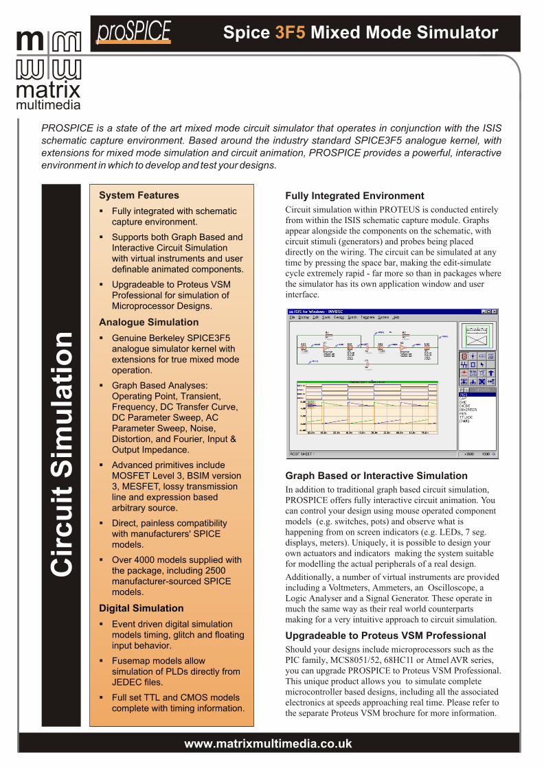
Fully Integrated Environment
Circuit simulation within PROTEUS is conducted entirely from within the ISIS schematic capture module. Graphs appear alongside the components on the schematic, with circuit stimuli (generators) and probes being placed directly on the wiring. The circuit can be simulated at any time by pressing the space bar, making the edit-simulate cycle extremely rapid - far more so than in packages where the simulator has its own application window and user interface.
Graph Based or Interactive Simulation
In addition to traditional graph based circuit simulation, PROSPICE offers fully interactive circuit animation. You can control your design using mouse operated component models (e.g. switches, pots) and observe what is happening from on screen indicators (e.g. LEDs, 7 seg. displays, meters). Uniquely, it is possible to design your own actuators and indicators making the system suitable for modelling the actual peripherals of a real design.
Additionally, a number of virtual instruments are provided including a Voltmeters, Ammeters, an Oscilloscope, a Logic Analyser and a Signal Generator. These operate in much the same way as their real world counterparts making for a very intuitive approach to circuit simulation.
Upgradeable to Proteus VSM Professional
Should your designs include microprocessors such as the PIC family, MCS8051/52, 68HC11 or Atmel AVR series, you can upgrade PROSPICE to Proteus VSM Professional. This unique product allows you to simulate complete microcontroller based designs, including all the associated electronics at speeds approaching real time. Please refer to the separate Proteus VSM brochure for more information.
PROSPICE is a state of the art mixed mode circuit simulator that operates in conjunction with the ISIS schematic capture environment. Based around the industry standard SPICE3F5 analogue kernel, with extensions for mixed mode simulation and circuit animation, PROSPICE provides a powerful, interactive environment in which to develop and test your designs.
System Features
§
§
§
Analogue Simulation
§
§
§
§
§
§
§
Fully integrated with schematic capture environment.
Supports both Graph Based and Interactive Circuit Simulation with virtual instruments and user definable animated components.
Upgradeable to Proteus VSM Professional for simulation of Microprocessor Designs.
Genuine Berkeley SPICE3F5 analogue simulator kernel with extensions for true mixed mode operation.
Graph Based Analyses: Operating Point, Transient, Frequency, DC Transfer Curve, DC Parameter Sweep, AC Parameter Sweep, Noise, Distortion, and Fourier, Input & Output Impedance.
§ Advanced primitives include MOSFET Level 3, BSIM version 3, MESFET, lossy transmission line and expression based arbitrary source.
Direct, painless compatibility with manufacturers' SPICE models.
Over 4000 models supplied with the package, including 2500 manufacturer-sourced SPICE models.
Digital Simulation
Event driven digital simulation models timing, glitch and floating input behavior.
Fusemap models allow simulation of PLDs directly from JEDEC files.
Full set TTL and CMOS models complete with timing information.
Cir
cu
it S
imu
lati
on
Spice Mixed Mode Simulator3F5proSPICE

matrix
mmm mmmm
multimedia
www.matrixmultimedia.co.uk
Partial Simulation of Large Designs
Where PROTEUS is being used to enter an entire design for PCB layout, it may be inappropriate to run simulation experiments on the entire schematic. For example, it doesn’t usually make sense to simulate crystal oscillators as analogue circuits when testing the digital logic that they drive. PROSPICE saves you from carving up the schematic by supporting partial simulation of the design. The circuit topology is analysed and only those components located between the input stimuli and the measurement points are included the simulation. Furthermore, if the design can be divided into several sections, the results from the input side simulations can be used to drive the following sections of the design, thus reducing simulation times considerably.
Excellent Modelling Tools
If you need to create your own component models, PROTEUS provides an excellent environment in which to do so. The support for hierarchical design in ISIS enables you to create a virtual test jig in which the component model can be developed. This means that any changes to the model can be evaluated quickly and easily prior to storing the model as a pre-compiled netlist.
Alternatively, you can use the VSM API to implement both analogue and digital models within Windows DLLs using a programming language such as C++. The VSM API can also be used to implement graphical functionality for complex animated components.
SPICE3F5 Simulator Kernel
PROSPICE is based around the industry standard SPICE analogue simulator developed at Berkeley University, California. SPICE3F5 is the latest version of SPICE and contains the latest convergence techniques and primitive models. PROSPICE uses Berkeley’s source code wherever possible, guaranteeing best possible compatibility both in terms of numerical results, and support for manufacturers’ SPICE models.
True Mixed Mode Simulation
PROSPICE incorporates a number of extensions to standard SPICE which allow it to model digital circuitry using an event driven paradigm. This is much more efficient that attempting to model the transistor level behaviour. When both analogue and digital parts are present, both techniques are used in parallel giving optimum performance and accuracy.
Fully Compatible with Manufacturers’ Models
More and more component manufacturers are providing SPICE models for their wares as well as the traditional data books. By choosing PROSPICE you will be able to gain maximum benefit from this resource - we have made a point of using Berkely code to parse the SPICE netlists in order to guarantee best possible compatibility. And to get you started, we have gathered over 4000 SPICE models from the Internet and linked them to appropriate schematic symbols in ISIS.
Feature Rich Digital Simulation
PROSPICE incorporates a fully featured event driven digital simulator which is automatically invoked whenever digital components are present. The digital simulation paradigm correctly models timing, glitch behaviour, floating inputs and undefined states - beware that not all so called mixed mode simulators are anything like as good.
PLD Modelling
PROSPICE includes special digital primitives which represent PLD fusemaps. These devices can be used to construct models of any programmable logic device. Specific models for popular PLD devices are included in the supplied component libraries.
The information on how the device is programmed is read directly from the JEDEC file produced by your PLD assembler. Therefore, you are not tied to using any particular PLD development system.
“Once again, Labcenter has concentrated on the essentials and presented these in depth rather than provide a lot of peripheral features of marginal use. In doing so it has produced an excellent all round simulator. You are unlikely to be in a position of requiring a particular basic simulation in detail, but finding that the program does not provide it, as you may be with other programs in this sector of the market.”
Electronics & Wireless World Review - October 1999
Spice Mixed Mode Simulator3F5proSPICE

Layout Database
ARES features a state of the art layout database capable of representing the most complex of PCB designs. Placement resolution is 10 nanometers within a maximum board size of 20m. Components and other objects may be rotated in 0.1 degree increments whilst padstacks facilitate the achievement of maximum routing area on inner layers.
Netlist & Ratsnest Handling
During the placement phase, ARES displays both the ratsnest and force vectors. Both are updated in real time when you drag components. The ratsnest is also automatically updated during routing - add a track and a ratsnest line will disappear; delete a track and one will re-appear.
The system fully supports design modifications - if you change the schematic and re-load the netlist, ARES will flag up exactly which components and/or tracks are affected. Equally, pin-swaps and gate-swaps made in ARES are automaticaly fed back to the schematic.
Route Placement & Editing
Manual routing makes no requirement that you start from the ratsnest lines (rubberbanding). You can place tracking in any way you wish and ARES will remove ratsnest lines as the connections are actually completed.
When editing routes, you can re-route or delete any section of a track, irrespective of how it was originally placed. Commands are also provided to change the thickness and/or layer of any section of tracking.
If thick tracks are laid between obstacles such as IC pads, ARES will automatically insert a narrower 'neck' in order to maintain the current design rules.
Curved tracks can be laid down simply by pressing the CTRL key and marking the route with the mouse.
Our high performance netlist based PCB design software perfectly complements ISIS. Incorporating both automatic component placement and a highly effective rip-up and retry auto-router, ARES takes the strain off you and makes your PC do the work. On the other hand, if you prefer to route your boards manually, the system places relatively few restrictions on how you go about the task.
Features
§
§
§
§
§
§
§
§
§
§
§
Design Automation
Layers: 16 copper, 2 silk screen, 4 mechanical plus board edge, keepout, resist and solder mask.
Any angle component placement and pad-stacks.
Fully automatic ratsnest and force vector generation.
Drag and Drop pin-swap/gateswap.
Acclaimed manual routing system is ideal for netlist based manual routing.
Gridless, polygonal power planes with full control of fill style and thermals.
Connectivity and physical design rule checkers to prove design integrity.
Package library includes SMT and THP parts.
Output to any Windows device including pen plotters.
Full set of CADCAM output and view facilities.
Pick and Place file for automatic insertion machines.
§ Automatic Component Placement.
§ Multi-strategy grid based auto-routing.
§ Special routines for SMT fanouts.
§ Rip-Up & Retry for 100% routing on most boards.
§ Tidy pass reduces via count and track length.
PC
B D
es
ign
A R E Sdvanced outing & diting oftwareARES
matrix
mmm mmmm
multimedia
www.matrixmultimedia.co.uk

Power Planes
ARES features the ultimate in power plane support - user placeable polygonal regions within which inner boundaries are automatically created around existing pads and tracking. Change the pads and tracking and the boundaries are recomputed to maintain design rule clearances. Thermal reliefs are supported and you can choose whether to hatch or fill each polygon. All computation is based on gridless shape geometry and occurs in the background so that you can carry on working on the design.
Design Rule Checks
During manual routing, ARES checks each track as you place it and warns you if any design rules (physical/electrical) are broken. You can also run global physical and electrical design rule checks at any time. The latter produces a report listing any missing or extra connections.
Package Libraries
The supplied libraries cover a large range of through hole components including all the most common IC, transistor, diode and connector packaging types. We also supply as standard, libraries for both discrete and IC SMT footprints; the latter including SOP, SOJ, PLCC, CLCC, QFP and PQFP types.
New packages can be created directly on the drawing whilst ARES also supports general 2D drafting features.
CADCAM Outputs
As well as providing the basic ability to output your PCB to standard Windows printers, ARES provides an optimized HPGL driver for pen plotters, and a full set of features for professional board manufacturing.
Gerber is supported in both RS274D and the newer RS274X formats whilst a standard Excellon format file is produced for drilling machines. In addition, an ASCII file
listing component positions and orientations is produced for use with Pick and Place machinery.
A Gerber Viewer is also provided allowing you to check that Gerber files contain the expected data prior to issuing them for manufacture.
Auto-Placement (not included as standard)
Automatic component placement makes it possible to design an entire board with the absolute minimum of effort on your part. Alternatively, since the placer can operate interactively, you can pre-place critical components first and the let ARES auto-place the rest.
Auto-Routing
Our grid based router is both flexible and fast and can route using any track thickness or via width, at 90 or 45 degrees, and on 1-8 layers. It was placed in the top Category A in the recent review of PCB software (EWW, May 1998).
The range of routing grids available enables you to trade off routing density against execution speed with densities of 1, 2 or 3 traces between IC pads. The router also has special routines which enable it form 'fan outs' from rows of SMT pads which would otherwise be off grid, thus enabling it to perform well with boards containing SMT parts.
The Rip-Up & Retry mode enables it to remove and replace tracks which block others giving 100% completion on most medium density boards routed at 50 or 25 thou. Meanwhile, our innovative costing/scheduling logic reduces the via count by as much as four fold over other low-medium cost routers.
Finally, you can run a tidy pass which reduces both track length and via count whilst improving the aesthetic quality of your board at the same time.
“PROTEUS from Labcenter stands out as the best all-round program in this review. While the other programs reviewed have strengths at various places in the pcb design process, Proteus maintains a constant high level of capability throughout. Whether it is a well turned out , user-friendly interactive routing, effective and configurable auto-placing, competent autorouteing, or a combination of autorouteing and interactive routing, handles everything very well.”
schematicPROTEUS
Electronics & Wireless World CAD Review Roundup - Sept 1998
matrix
mmm mmmm
multimedia
www.matrixmultimedia.co.uk
A R E Sdvanced outing & diting oftwareARES

Proteus PCB Design is available in five levels offering a range of design capacities and features to match your application. Level 1 is limited on both pin count and features whilst Level 2 is limited only in terms of design capacity and offers the full set of features. Level 3 is completely unlimited.
PCB DESIGN LIMITS
PROTEUS Levels 1 and 2 impose a limit for the number of pins in the netlist. These limits apply when loading it into ARES. Any number of pins may be placed on the PCB iteself, however, enabling you to exceed the limit by the odd component should the need arise.
Levels 1+ and 2+ offer double the design capacity but are otherwise identical.
POWER PLANES
All levels of PROTEUS handle power planes using shape
THE PROTEUS PCB DESIGN PRODUCT RANGETHE PROTEUS PCB DESIGN PRODUCT RANGE
PROTEUS PCB DESIGN
Max Number of Pins in Netlist
Shape based power planes
Standard Auto-routing
Rip-up and Retry Routing
Auto-Placement
Gate-Swap Optimizer
LEVEL 1/1+ LEVEL 2/2+ LEVEL 3
1000/2000 1000/2000 Unlimited
1 per layer Unlimited Unlimited
ü ü ü
ü ü
ü ü
ü ü
The PROSPICE mixed mode simulator is also available as an option for any of the levels, should you not require the microprocessor simulation capability offered by Proteus VSM Professional.
based polygon merging. However, in Level 1, only one power plane is allowed per layer - partial power planes and multiple power planes on one layer are supported in Levels 2 and 3 only.
AUTOROUTING
All PROTEUS Levels include a sophisticated multi-strategy autorouter.
In Levels 2 and 3, you also get rip-up and retry operation which will give 100% completion on all but the most complex or densely packed boards.
Proteus VSM is an extension of the PROSPICE simulator that facilitates the simulation of microprocessor based designs including all the associated electronics. Furthermore, you can interact with the microcontroller software through the use of animated keypads, switches, buttons, LEDs, lamps and even LCD displays. Please refer to the separate leaflet for further information.
Virtual System Modelling and optionsmatrix
mmm mmmm
multimedia
www.matrixmultimedia.co.uk
Standard package is Level 1 - 50 user bundle is for level 3
Features
§
§
§
§
CPU models available for many popular micro-controllers including PIC, AVR, HC11 and 8051.
Interactive device models include LED and LCD displays, RS232 terminal, universal keypad plus a range of switches, buttons, pots, LEDs, 7 seg displays and more.
Extensive debugging facilities including register and memory contents, breakpoints and single step modes.
Source level debugging for selected development tools including IAR C-SPY and Keil uVision 2.
§
§
Integrated ‘make’ utility - compile and simulate with one keystroke.
DLL interfaces for application specific models. Full documentation supplied with the package.