Embed Size (px)
Citation preview

Manual Par Manual Re
MV 1 SERIES
GAS STEAMER
OWNER’S MANUAL
Click here for
Parts List
Country of Destination GB and IE
t No: 931762-01 MV1 Gas Steamer - 1 – v No: 2

Manual Part No: 931762-01 MV1 Gas Steamer - 2 – Manual Rev No: 2
Model No. Product Description Rev. Date Flexible Hose
Size MV1STA60-NG MV1STA60-LP
MV Gas Steamer 600 Steamer 2 Stage Door 600 Steamer 2 Stage Door
2 2
14/10/05 14/10/05
½” BSP hose ½” BSP hose
Manual Part No: 931762-01 MV1 Gas Steamer - 3 – Manual Rev No: 2
INDEX
Page Cover Sheet: 1 Revision Sheet: 2 Index: 3 Introduction: 4 & 5
General Introduction 4 Important Note 5
Specification: 6 & 7
Gas Pressure / Connection 6 Dimensions 7
Installation: 8 - 10
Important Note 8 Positioning 8 Checking & Commissioning 8 - 10
User’s Instruction: 11 - 13
Important Note 11 Operation 12 & 13 Cooking Guide 13 Cleaning 13
Service & Maintenance: 14 - 16
Instructions 14 & 15 Fault Finding 16
Spare Parts: 17 & 18 Warranty Cover Sheet: 19
Manual Part No: 931762-01 MV1 Gas Steamer - 4 – Manual Rev No: 2
INTRODUCTION This manual contains all the required information to ensure that your new appliance is installed correctly and that you have all the information necessary to identify and order spare parts. It also contains comprehensive instructions for the user and for cleaning the appliance. To maintain peak performance, it is recommended that the appliance be regularly serviced and that when ordering spare parts, reference be made to the appropriate list quoting the Part No. and the description therein. THE FITTING OF A NON-STANDARD PART MAY VOID ANY GUARANTEE. All work carried out on this appliance during installation or servicing must be performed by a competent person and the connection of the appliance to the gas supply MUST be carried out by qualified personnel in accordance, where applicable, with the relevant regulations. The siting of the appliance and the connection to the gas supply must comply with the latest GAS SAFETY REGULATIONS 2000: the requirements of the FIRE PRECAUTIONS ACT 1971; the HEALTH & SAFETY AT WORK, ETC ACT 1974, the BUILDING STANDARDS (SCOTLAND) CONSOLIDATION REGULATIONS 1971. Detailed recommendations are contained in British Standards BS5440 Part 1:2000, BS5440 Part 2:2000, BS5588: Part 0:1996, BS5588: Part 11:1997 & BS6173: 2001. An easily accessible stopcock must be fitted in the gas supply adjacent to the appliance for use in emergency. The details of the gas supply will be found on the Data Plate, which is located on the rear of the flue upstand/splashback panel. This appliance must be equi-potentially earth bonded. Improvements The policy of Viscount Catering Ltd is such that, each product is subject to continual development and may, therefore, be subsequently improved. The company reserves the right to alter the design of any appliance without prior notification and without the responsibility to update any delivered or in-service appliance and furthermore, without incurring the responsibility for altering these instructions. In such circumstances, it may be found that the appliance detailed herein differs in certain respects from the one supplied. IT IS IMPORTANT, THEREFORE, TO QUOTE THE SERIAL No. AND THE APPLIANCE MODEL No. IN ALL COMMUNICATIONS WITH THE COMPANY
Manual Part No: 931762-01 MV1 Gas Steamer - 5 – Manual Rev No: 2
Introduction (cont.) Important Before installing any item please refer to the installation instructions. We recommend that all servicing other than routine cleaning be carried out by our authorised service agents and will accept no responsibility for work carried out by other persons. For satisfactory operation, parts of catering equipment become hot. Suitable precautions must be taken to avoid accidental burns therefore the appliance should be positioned to minimise the possibility of accidental touching. It is the supervisor’s responsibility to warn users to wear suitable protection and to follow correct operation and cleaning procedures. For the details of your nearest Service Agent for all warranty and repair work, you should contact: - The Service Manager, Viscount Catering Limited Provincial Park Nether Lane Ecclesfield Sheffield S35 9ZX Tel: +44 (0) 114 2574500 Fax: +44 (0) 114 2574527 Spares can be obtained via the Spare Parts Department at the above address. IT IS IMPORTANT, TO QUOTE THE SERIAL No. AND THE APPLIANCE MODEL No. IN ALL COMMUNICATIONS WITH THE COMPANY.
Manual Part No: 931762-01 MV1 Gas Steamer - 6 – Manual Rev No: 2
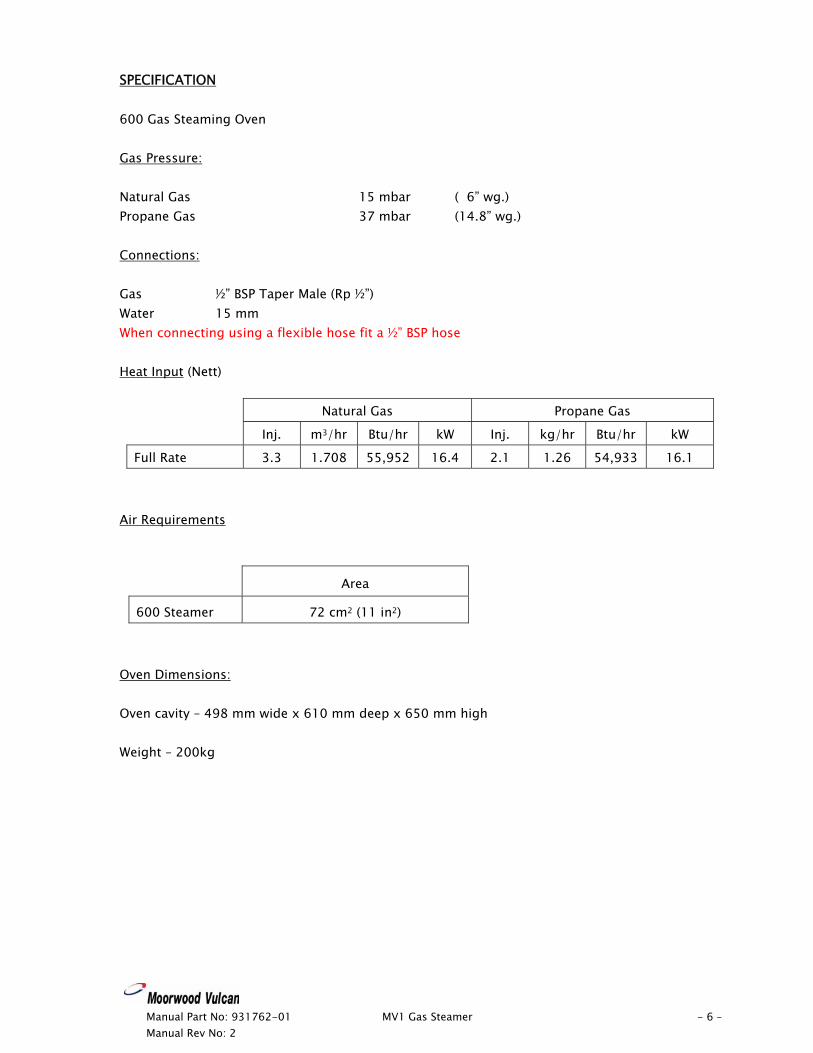
SPECIFICATION 600 Gas Steaming Oven Gas Pressure: Natural Gas 15 mbar ( 6” wg.) Propane Gas 37 mbar (14.8” wg.) Connections: Gas ½” BSP Taper Male (Rp ½”) Water 15 mm When connecting using a flexible hose fit a ½” BSP hose Heat Input (Nett)
Natural Gas Propane Gas
Inj. m3/hr Btu/hr kW Inj. kg/hr Btu/hr kW
Full Rate 3.3 1.708 55,952 16.4 2.1 1.26 54,933 16.1
Air Requirements
Area
600 Steamer 72 cm2 (11 in2)
Oven Dimensions: Oven cavity – 498 mm wide x 610 mm deep x 650 mm high Weight – 200kg

Specification (cont.)
700
600
3535 3523
0
180
445
305
900
150
1674
DRAIN
WAT
ER
GAS
803
768
1709
35
Manual Part No: 931762-01 MV1 Gas Steamer - 7 – Manual Rev No: 2
Manual Part No: 931762-01 MV1 Gas Steamer - 8 – Manual Rev No: 2
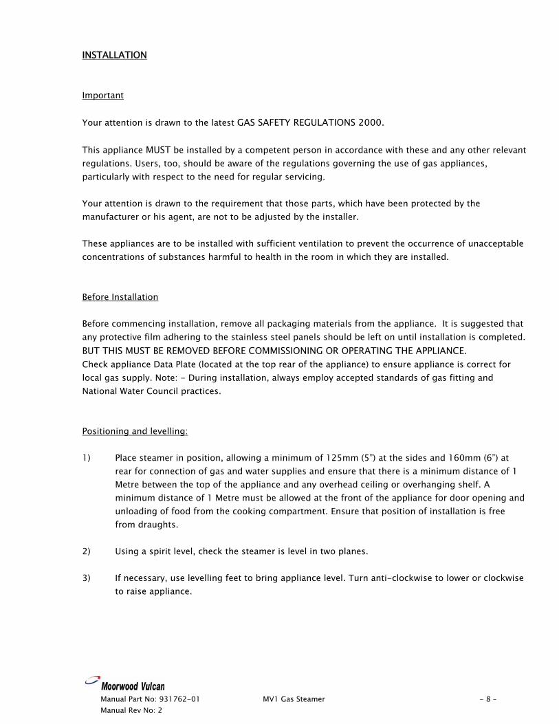
INSTALLATION Important Your attention is drawn to the latest GAS SAFETY REGULATIONS 2000. This appliance MUST be installed by a competent person in accordance with these and any other relevant regulations. Users, too, should be aware of the regulations governing the use of gas appliances, particularly with respect to the need for regular servicing. Your attention is drawn to the requirement that those parts, which have been protected by the manufacturer or his agent, are not to be adjusted by the installer. These appliances are to be installed with sufficient ventilation to prevent the occurrence of unacceptable concentrations of substances harmful to health in the room in which they are installed. Before Installation Before commencing installation, remove all packaging materials from the appliance. It is suggested that any protective film adhering to the stainless steel panels should be left on until installation is completed. BUT THIS MUST BE REMOVED BEFORE COMMISSIONING OR OPERATING THE APPLIANCE. Check appliance Data Plate (located at the top rear of the appliance) to ensure appliance is correct for local gas supply. Note: - During installation, always employ accepted standards of gas fitting and National Water Council practices. Positioning and levelling: 1) Place steamer in position, allowing a minimum of 125mm (5”) at the sides and 160mm (6”) at
rear for connection of gas and water supplies and ensure that there is a minimum distance of 1 Metre between the top of the appliance and any overhead ceiling or overhanging shelf. A minimum distance of 1 Metre must be allowed at the front of the appliance for door opening and unloading of food from the cooking compartment. Ensure that position of installation is free from draughts.
2) Using a spirit level, check the steamer is level in two planes. 3) If necessary, use levelling feet to bring appliance level. Turn anti-clockwise to lower or clockwise
to raise appliance.
Manual Part No: 931762-01 MV1 Gas Steamer - 9 – Manual Rev No: 2
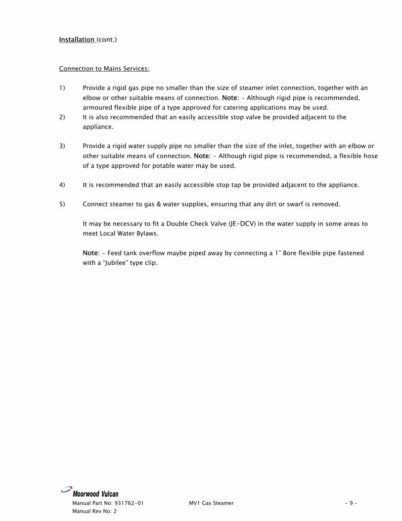
Installation (cont.) Connection to Mains Services: 1) Provide a rigid gas pipe no smaller than the size of steamer inlet connection, together with an
elbow or other suitable means of connection. Note: - Although rigid pipe is recommended, armoured flexible pipe of a type approved for catering applications may be used.
2) It is also recommended that an easily accessible stop valve be provided adjacent to the appliance.
3) Provide a rigid water supply pipe no smaller than the size of the inlet, together with an elbow or
other suitable means of connection. Note: - Although rigid pipe is recommended, a flexible hose of a type approved for potable water may be used.
4) It is recommended that an easily accessible stop tap be provided adjacent to the appliance. 5) Connect steamer to gas & water supplies, ensuring that any dirt or swarf is removed.
It may be necessary to fit a Double Check Valve (JE-DCV) in the water supply in some areas to meet Local Water Bylaws.
Note: - Feed tank overflow maybe piped away by connecting a 1” Bore flexible pipe fastened with a “Jubilee” type clip.
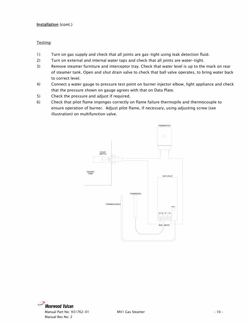
Installation (cont.) Testing: 1) Turn on gas supply and check that all joints are gas-tight using leak detection fluid. 2) Turn on external and internal water taps and check that all joints are water-tight. 3) Remove steamer furniture and interceptor tray. Check that water level is up to the mark on rear
of steamer tank. Open and shut drain valve to check that ball valve operates, to bring water back to correct level.
4) Connect a water gauge to pressure test point on burner injector elbow, light appliance and check that the pressure shown on gauge agrees with that on Data Plate.
5) Check the pressure and adjust if required. 6) Check that pilot flame impinges correctly on flame failure thermopile and thermocouple to
ensure operation of burner. Adjust pilot flame, if necessary, using adjusting screw (see illustration) on multifunction valve.
TP THTP TH
THERMOSTAT
GAS VALVE
WHITERED
THERMOPILE
THERMOCOUPLE
HEADERTANK
FLOATSWITCH
PILOT
Manual Part No: 931762-01 MV1 Gas Steamer - 10 – Manual Rev No: 2
Manual Part No: 931762-01 MV1 Gas Steamer - 11 – Manual Rev No: 2
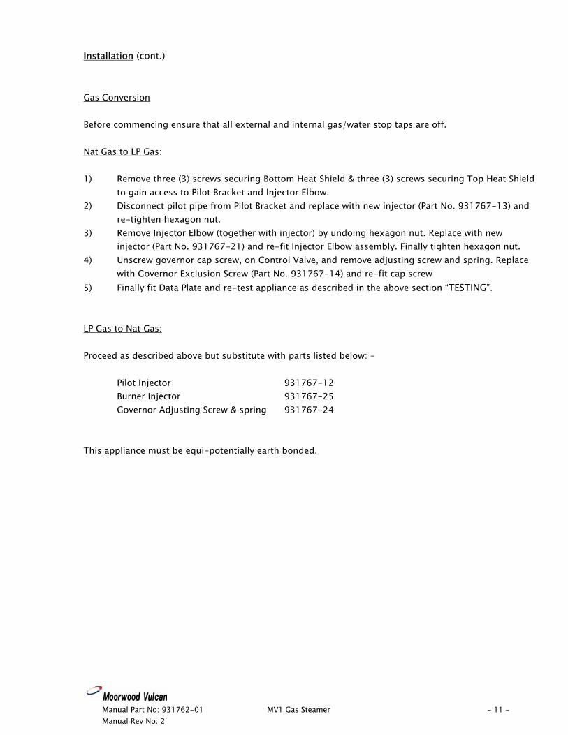
Installation (cont.) Gas Conversion Before commencing ensure that all external and internal gas/water stop taps are off. Nat Gas to LP Gas: 1) Remove three (3) screws securing Bottom Heat Shield & three (3) screws securing Top Heat Shield
to gain access to Pilot Bracket and Injector Elbow. 2) Disconnect pilot pipe from Pilot Bracket and replace with new injector (Part No. 931767-13) and
re-tighten hexagon nut. 3) Remove Injector Elbow (together with injector) by undoing hexagon nut. Replace with new
injector (Part No. 931767-21) and re-fit Injector Elbow assembly. Finally tighten hexagon nut. 4) Unscrew governor cap screw, on Control Valve, and remove adjusting screw and spring. Replace
with Governor Exclusion Screw (Part No. 931767-14) and re-fit cap screw 5) Finally fit Data Plate and re-test appliance as described in the above section “TESTING”. LP Gas to Nat Gas: Proceed as described above but substitute with parts listed below: - Pilot Injector 931767-12 Burner Injector 931767-25 Governor Adjusting Screw & spring 931767-24 This appliance must be equi-potentially earth bonded.
Manual Part No: 931762-01 MV1 Gas Steamer - 12 – Manual Rev No: 2
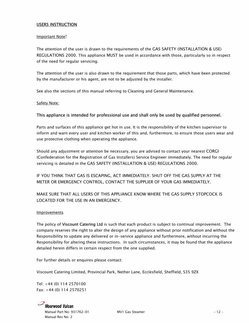
USERS INSTRUCTION Important Note! The attention of the user is drawn to the requirements of the GAS SAFETY (INSTALLATION & USE) REGULATIONS 2000. This appliance MUST be used in accordance with those, particularly so in respect of the need for regular servicing. The attention of the user is also drawn to the requirement that those parts, which have been protected by the manufacturer or his agent, are not to be adjusted by the installer. See also the sections of this manual referring to Cleaning and General Maintenance. Safety Note: This appliance is intended for professional use and shall only be used by qualified personnel. Parts and surfaces of this appliance get hot in use. It is the responsibility of the kitchen supervisor to inform and warn every user and kitchen worker of this and, furthermore, to ensure those users wear and use protective clothing when operating the appliance. Should any adjustment or attention be necessary, you are advised to contact your nearest CORGI (Confederation for the Registration of Gas Installers) Service Engineer immediately. The need for regular servicing is detailed in the GAS SAFETY (INSTALLATION & USE) REGULATIONS 2000. IF YOU THINK THAT GAS IS ESCAPING, ACT IMMEDIATELY. SHUT OFF THE GAS SUPPLY AT THE METER OR EMERGENCY CONTROL, CONTACT THE SUPPLIER OF YOUR GAS IMMEDIATELY. MAKE SURE THAT ALL USERS OF THIS APPLIANCE KNOW WHERE THE GAS SUPPLY STOPCOCK IS LOCATED FOR THE USE IN AN EMERGENCY. Improvements The policy of Viscount Catering Ltd is such that each product is subject to continual improvement. The company reserves the right to alter the design of any appliance without prior notification and without the Responsibility to update any delivered or in-service appliance and furthermore, without incurring the Responsibility for altering these instructions. In such circumstances, it may be found that the appliance detailed herein differs in certain respect from the one supplied. For further details or enquires please contact: Viscount Catering Limited, Provincial Park, Nether Lane, Ecclesfield, Sheffield, S35 9ZX Tel: +44 (0) 114 2570100 Fax: +44 (0) 114 2570251
Manual Part No: 931762-01 MV1 Gas Steamer - 13 – Manual Rev No: 2
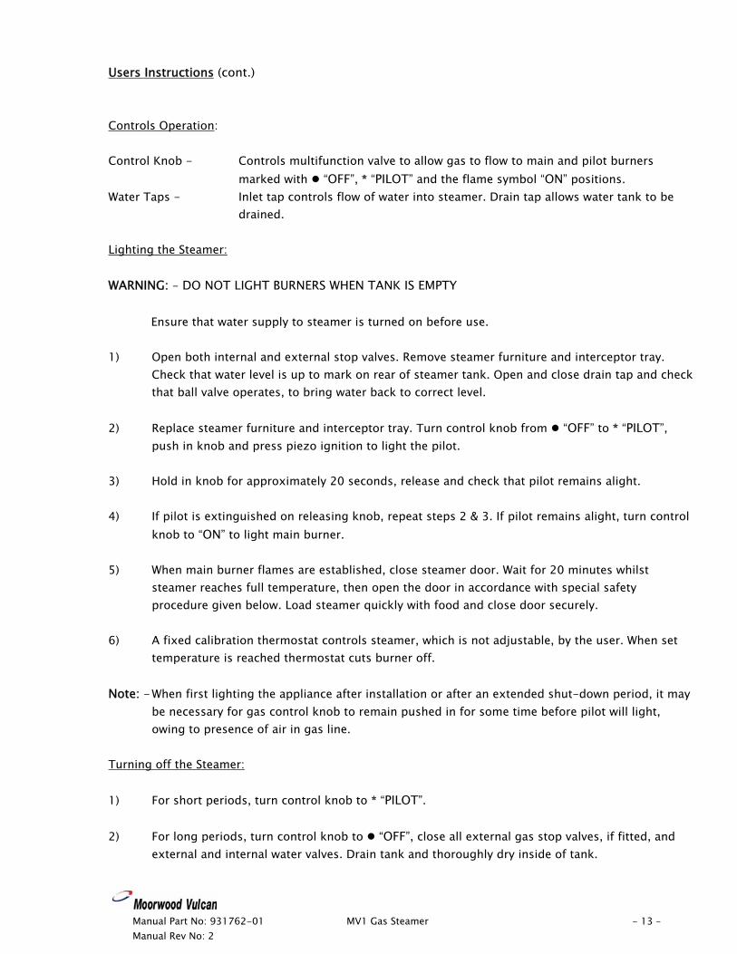
Users Instructions (cont.) Controls Operation: Control Knob - Controls multifunction valve to allow gas to flow to main and pilot burners
marked with “OFF”, * “PILOT” and the flame symbol “ON” positions. Water Taps - Inlet tap controls flow of water into steamer. Drain tap allows water tank to be
drained. Lighting the Steamer: WARNING: - DO NOT LIGHT BURNERS WHEN TANK IS EMPTY
Ensure that water supply to steamer is turned on before use. 1) Open both internal and external stop valves. Remove steamer furniture and interceptor tray.
Check that water level is up to mark on rear of steamer tank. Open and close drain tap and check that ball valve operates, to bring water back to correct level.
2) Replace steamer furniture and interceptor tray. Turn control knob from “OFF” to * “PILOT”,
push in knob and press piezo ignition to light the pilot. 3) Hold in knob for approximately 20 seconds, release and check that pilot remains alight. 4) If pilot is extinguished on releasing knob, repeat steps 2 & 3. If pilot remains alight, turn control
knob to “ON” to light main burner. 5) When main burner flames are established, close steamer door. Wait for 20 minutes whilst
steamer reaches full temperature, then open the door in accordance with special safety procedure given below. Load steamer quickly with food and close door securely.
6) A fixed calibration thermostat controls steamer, which is not adjustable, by the user. When set
temperature is reached thermostat cuts burner off. Note: - When first lighting the appliance after installation or after an extended shut-down period, it may
be necessary for gas control knob to remain pushed in for some time before pilot will light, owing to presence of air in gas line.
Turning off the Steamer: 1) For short periods, turn control knob to * “PILOT”. 2) For long periods, turn control knob to “OFF”, close all external gas stop valves, if fitted, and
external and internal water valves. Drain tank and thoroughly dry inside of tank.
Manual Part No: 931762-01 MV1 Gas Steamer - 14 – Manual Rev No: 2
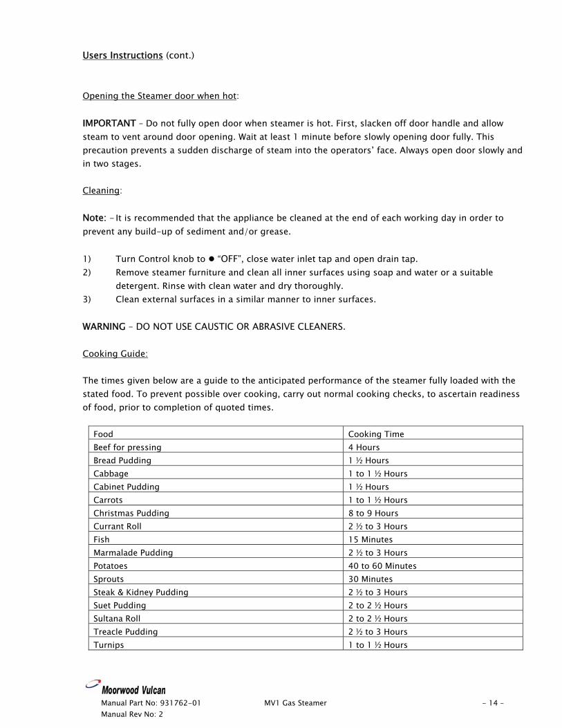
Users Instructions (cont.) Opening the Steamer door when hot: IMPORTANT – Do not fully open door when steamer is hot. First, slacken off door handle and allow steam to vent around door opening. Wait at least 1 minute before slowly opening door fully. This precaution prevents a sudden discharge of steam into the operators’ face. Always open door slowly and in two stages. Cleaning: Note: - It is recommended that the appliance be cleaned at the end of each working day in order to prevent any build-up of sediment and/or grease. 1) Turn Control knob to “OFF”, close water inlet tap and open drain tap. 2) Remove steamer furniture and clean all inner surfaces using soap and water or a suitable
detergent. Rinse with clean water and dry thoroughly. 3) Clean external surfaces in a similar manner to inner surfaces. WARNING – DO NOT USE CAUSTIC OR ABRASIVE CLEANERS. Cooking Guide: The times given below are a guide to the anticipated performance of the steamer fully loaded with the stated food. To prevent possible over cooking, carry out normal cooking checks, to ascertain readiness of food, prior to completion of quoted times.
Food Cooking Time Beef for pressing 4 Hours Bread Pudding 1 ½ Hours Cabbage 1 to 1 ½ Hours Cabinet Pudding 1 ½ Hours Carrots 1 to 1 ½ Hours Christmas Pudding 8 to 9 Hours Currant Roll 2 ½ to 3 Hours Fish 15 Minutes Marmalade Pudding 2 ½ to 3 Hours Potatoes 40 to 60 Minutes Sprouts 30 Minutes Steak & Kidney Pudding 2 ½ to 3 Hours Suet Pudding 2 to 2 ½ Hours Sultana Roll 2 to 2 ½ Hours Treacle Pudding 2 ½ to 3 Hours Turnips 1 to 1 ½ Hours
Manual Part No: 931762-01 MV1 Gas Steamer - 15 – Manual Rev No: 2
User Instructions (cont.) This equipment is designed and manufactured to give you a long, satisfactory service at low cost, provided that it is given proper care and attention at all times. Frequent cleaning and regular checking of correct adjustment, will be rewarded by reduced operating and maintenance costs, minimum downtime and regular results from your cooking. WE RECOMMEND THAT ALL EQUIPMENT IS SERVICED AT LEAST ONCE A YEAR, BUT MAY BE AS FREQUENT AS 6 MONTHS OR LESS. SERVICE INTERVALS CAN BE AFFECTED BY SPILLAGE AND SHOULD BE ASSESSED EACH TIME THE EQUIPMENT HAS BEEN USED.
Manual Part No: 931762-01 MV1 Gas Steamer - 16 – Manual Rev No: 2
SERVICE AND MAINTENANCE Maintenance MUST only be carried out by a competent person. Ensure that the gas and electricity supply to the appliance has been turned “OFF” before dismantling any components. 1) Turn the steamer on and check that the gas pressure at the test point is as stated on the date
plate. 2) Remove the oven shelves and the lower panel covering the top of the steam generator tank, and
check the water level against the level indicator at the back of the tank. If level is incorrect, remove the front control panel and adjust the float to re-set the water to the correct level.
3) Drain an amount of water from the generator tank and check that the water re-fills to the correct
level, checking that the water flow is unobstructed between the header tank and the steam generator tank. NOTE! It is possible to remove the end cap from the pipework to enable the connecting water pipe to be cleared of any blockage. De-scale the tank as required.
4) Remove the two screws fixing the control panel, and check that the float switch operation is
satisfactory by depressing the float below the water level, noting that the main burner goes out and then re-lights as the float switch is released. Also check that the cross lighting between pilot and burner is smooth and positive.
Any scale build up on the float switch or float valve must be removed.
5) Replace oven shelves, generator tank top cover and control panel. 6) Remove the four screws securing lower heat shield, followed by three screws securing the upper
heat shield in the bottom compartment of the steamer. 7) Check that the pilot flame is satisfactory and that the flame is impinging correctly on the
thermocouple and thermopile probes. 8) Brush clean the main burner and clear the burner ports of any lint build up as required. 9) Re-fit the heat shield in lower compartment. 10) Insert a thermometer probe into the steam outlet vent in the top panel of the steamer. 11) Turn the steamer on and observe the temperature rise on the thermometer. The thermostat
should cut off 97°C to 98°C. Adjust the thermostat as required. 12) The thermostat should cut back in at approximately 88°C. 13) Check the condition of the door seals
Manual Part No: 931762-01 MV1 Gas Steamer - 17 – Manual Rev No: 2
SERVICE AND MAINTENANCE (cont.) Multifunctional Control Valve: 1) Turn off gas supply. 2) Disconnect pilot pipe from valve. 3) Disconnect union fittings from valve inlet & outlet. 4) Transfer gas fittings to new valve and re-fit in reverse order. 5) Check for gas tightness and test (see “TESTING” on page 9). Thermostat: 1) Turn off gas supply. 2) Unscrew vent from steamer top panel. 3) Remove two screws from back of top panel and remove by lifting at rear and sliding forward. 4) Remove insulation and release gland-fixing nut. 5) Working inside the steaming compartment release the phial from its bracket and feed through
tank top. 6) Remove thermostat by undoing its two fixing screws. 7) Disconnect the two wires on the thermostat. 8) Replace new part by reversing the above procedure. Thermocouple/Thermopile: 1) Disconnect from the multifunctional valve. 2) Remove the three screws fastening the bottom heat shield and withdraw followed by the three
screws fixing the top heat shield. 3) Unscrew thermocouple/thermopile and withdraw from the pilot bracket assembly. 4) Fit new thermocouple/thermopile by reversing the above procedure. Burner: 1) Turn off gas supply. 2) Remove three screws securing bottom heat shield and withdraw shield followed by the three
screws fixing the top heat shield. 3) Disconnect pilot pipe at pilot, (taking care not to lose pilot injector) and burner feed pipe
coupling. 4) The burner can now be withdrawn complete with pilot assembly. 5) Re-fit burner assembly by reversing the above procedure.
Manual Part No: 931762-01 MV1 Gas Steamer - 18 – Manual Rev No: 2
Service and Maintenance (cont.) Pilot Assembly 1) Turn off gas supply. 2) Remove four screws securing lower heat shield and withdraw shield followed by the three screws
fixing the top heat shield. 3) Disconnect thermocouple and thermopile from the pilot bracket. 4) Disconnect pilot pipe from pilot bracket, taking care not to lose pilot injector. 5) Remove nut & washer securing pilot assembly to burner. 6) Remove two screws and nuts securing pilot assembly to bracket. 7) Re-fit pilot assembly by reversing the above procedure. Water Inlet Valve: 1) Turn off water supply. 2) Remove two screws and lift off fascia panel. 3) Disconnect union at inlet of valve. 4) Slacken lock nuts and withdraw valve complete with ball float from break tank. 5) Overhaul or renew valve and refit by reversing removal procedure. 6) Turn on water supply and check operation of inlet valve, see: “TESTING” on page 9. Doors: Steamer Compartment 1) Remove caps from door hinges, exposing fixing screws. 2) Release fixing screws, being careful not to lose spacing shim. 3) Repeat step (2) and lift door away. 4) Refit by reversing removal procedure. Burner Compartment 1) Remove two screws securing bottom door hinge to base frame. 2) Lower door and remove, taking care not to lose door bushes. 3) Refit by reversing removal procedure. Float switch 1) Turn of the water supply and drain down. 2) Remove the two screws from the control panel to gain access to the header tank. 3) Disconnect the float switch wires from the control valve and the thermostat. Remove the back
nut from the float switch and pull switch and wires through the side of the header tank. 4) Re-fit by reversing the procedure, ensuring that the rubber seal is fitted to the inside of the tank
and checking for leaks when the water is turned on.
Manual Part No: 931762-01 MV1 Gas Steamer - 19 – Manual Rev No: 2
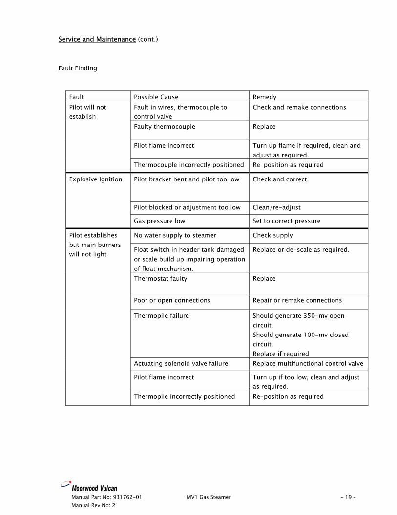
Service and Maintenance (cont.) Fault Finding
Fault Possible Cause Remedy Fault in wires, thermocouple to control valve
Check and remake connections
Faulty thermocouple Replace
Pilot flame incorrect Turn up flame if required, clean and adjust as required.
Pilot will not establish
Thermocouple incorrectly positioned Re-position as required
Pilot bracket bent and pilot too low Check and correct
Pilot blocked or adjustment too low Clean/re-adjust
Explosive Ignition
Gas pressure low Set to correct pressure
No water supply to steamer Check supply
Float switch in header tank damaged or scale build up impairing operation of float mechanism.
Replace or de-scale as required.
Thermostat faulty Replace
Poor or open connections Repair or remake connections
Thermopile failure Should generate 350-mv open circuit. Should generate 100-mv closed circuit. Replace if required
Actuating solenoid valve failure Replace multifunctional control valve
Pilot flame incorrect Turn up if too low, clean and adjust as required.
Pilot establishes but main burners will not light
Thermopile incorrectly positioned Re-position as required
Manual Part No: 931762-01 MV1 Gas Steamer - 20 – Manual Rev No: 2
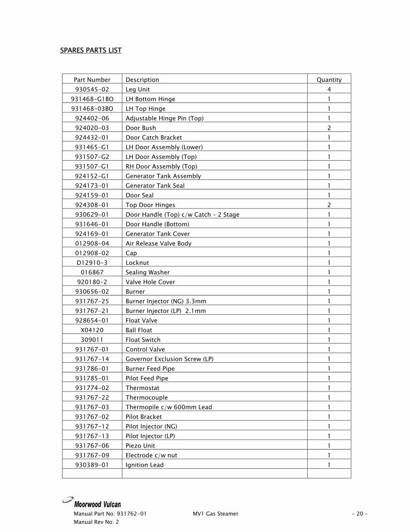
SPARES PARTS LIST
Part Number Description Quantity 930545-02 Leg Unit 4
931468-G1BO LH Bottom Hinge 1 931468-03BO LH Top Hinge 1
924402-06 Adjustable Hinge Pin (Top) 1 924020-03 Door Bush 2 924432-01 Door Catch Bracket 1 931465-G1 LH Door Assembly (Lower) 1 931507-G2 LH Door Assembly (Top) 1 931507-G1 RH Door Assembly (Top) 1 924152-G1 Generator Tank Assembly 1 924173-01 Generator Tank Seal 1 924159-01 Door Seal 1 924308-01 Top Door Hinges 2 930629-01 Door Handle (Top) c/w Catch – 2 Stage 1 931646-01 Door Handle (Bottom) 1 924169-01 Generator Tank Cover 1 012908-04 Air Release Valve Body 1 012908-02 Cap 1 D12910-3 Locknut 1
016867 Sealing Washer 1 920180-2 Valve Hole Cover 1
930656-02 Burner 1 931767-25 Burner Injector (NG) 3.3mm 1 931767-21 Burner Injector (LP) 2.1mm 1 928654-01 Float Valve 1
X04120 Ball Float 1 309011 Float Switch 1
931767-01 Control Valve 1 931767-14 Governor Exclusion Screw (LP) 1 931786-01 Burner Feed Pipe 1 931785-01 Pilot Feed Pipe 1 931774-02 Thermostat 1 931767-22 Thermocouple 1 931767-03 Thermopile c/w 600mm Lead 1 931767-02 Pilot Bracket 1 931767-12 Pilot Injector (NG) 1 931767-13 Pilot Injector (LP) 1 931767-06 Piezo Unit 1 931767-09 Electrode c/w nut 1 930389-01 Ignition Lead 1

Manual Part No: 931762-01 MV1 Gas Steamer - 21 – Manual Rev No: 2
Spares Part List (cont.)
Part Number Description Quantity 30000250 ‘O’ Ring 2 924104-02 Drain Valve 1
927061-01BO Drain Tube 1 926636-01 Gland Nut 2
JE-DCV Double Check Valve Optional
932129-01 Shelf (Aluminium) Standard 928358-01 Shelf (Stainless steel) Optional 920515-02 Baskets (Stainless Steel) Optional
XC60S-PS Shelf Kit (Aluminium) Optional XC60S-SS Shelf Kit (Stainless steel) Optional XC60S-SB Basket Accessory Kit (Stainless Steel) Optional
931980-G1 Wire Assembly Spares Kit 931811-S1 Conversion Kit - NG to LPG Spares Kit 931811-S2 Conversion Kit - LPG to NG Spares Kit
Spare Parts are available from: Viscount Catering Limited Provincial Park Nether Lane Ecclesfield Sheffield S35 9ZX Tel: +44 (0) 114 2574550 Fax: +44 (0) 114 2574520

Manual Part No: 931762-01 MV1 Gas Steamer - 22 – Manual Rev No: 2
VISCOUNT CATERING LIMITED
WWAARRRRAANNTTYY CCOOVVEERR
The Company offer twelve months warranty with each new piece of equipment subject to our normal conditions of sale and will undertake responsibility for warranty subject to the additional following conditions. Notice of the defect/damage is given within 48 hours of breakdown or in the case of damage four days from the date of despatch and the manufacturer given adequate opportunity to examine the goods in order that appropriate action can be taken. The Company will not be obliged to repair or replace any goods if after examination the defect/damage is found to be through accident, misuse, neglect, incorrect installation or maintenance by other than approved engineers, or any other cause beyond the reasonable control of the manufacturer. EXCLUSIONS TO WARRANTY Normal routine maintenance is not covered and the warranty specifically excludes any problems, which are related to scale caused by hard water and the cleaning of pilot jets. Also excluded from the warranty are the following consumable items.
Tap washers and springs, gaskets, oven lamps and indicating lights, door seals and any other perishable parts.
This warranty in no way prejudices your rights under common law and is offered as an addition to your statutory rights.

Manual Part No: 931762-01 MV1 Gas Steamer - 23 – Manual Rev No: 2