Embed Size (px)
Citation preview
598 M e t a lc la d Plu s Technical
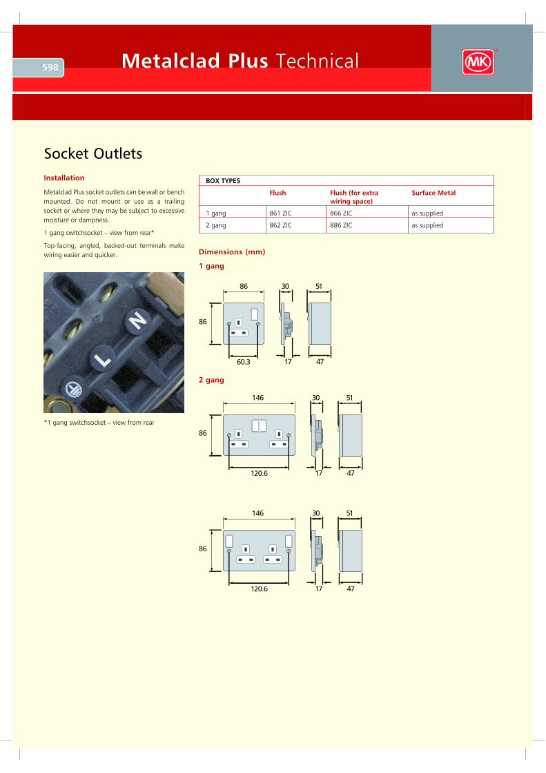
Socket Outlets
In s t a lla t io n
M etalclad P lu s s o ck et o u tlets can b e w all o r b ench
m o u nted . D o no t m o u nt o r u se as a trailing
s o ck et o r w here they m ay b e s u b ject to ex ces s iv e
m o is tu re o r d am p nes s .
1 g ang s w itchs o ck et – v iew fro m rear*
To p -facing , ang led , b ack ed -o u t term inals m ak e
w iring eas ier and q u ick er.
8 6
8 6
6 0 .3
3 0
17
5 1
4 7
14 6
8 6
12 0 .6
3 0
17
5 1
4 7
14 6
8 6
12 0 .6
3 0
17
5 1
4 7
1 g a n g
D im e n s io n s (m m )
2 g a n g
B O X T Y PE S
F lu s h F lu s h (f o r e x t r a S u r f a c e M e t a l
w ir in g s p a c e )
1 g ang 8 6 1 Z IC 8 6 6 Z IC as s u p p lied
2 g ang 8 6 2 Z IC 8 8 6 Z IC as s u p p lied
* 1 g ang s w itchs o ck et – v iew fro m rear
599Metalclad Plus Technical
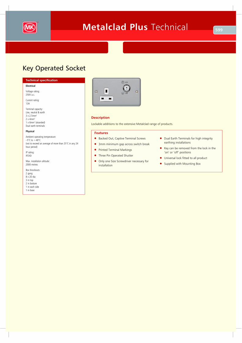
Key Operated Socket
Technical specification
Electrical
Voltage rating:
25 0 V a.c .
C u rrent rating:
1 3 A
T erm inal c ap ac ity :
L iv e, neu tral & earth
3 x 2.5 m m 2
2 x 4 m m 2
1 x 6 m m 2 (s trand ed )
D u al earth term inals
P h y s ical
A m b ient op erating tem p eratu re:
– 5 ° C to + 4 0 ° C
(not to ex c eed an av erage of m ore th an 25 ° C in any 24
h ou r p eriod )
IP rating:
IP 2X D
M ax . ins tallation altitu d e:
20 0 0 m etres
B ox K noc k ou ts :
2 gang
8 x 20 d ia
3 in top
2 in b ottom
1 in eac h s id e
1 in b as e
Description
L ockable additions to the extensive Metalclad range of products.
B acked O ut, Captive Terminal S crews
3 mm minimum gap across switch break
Printed Terminal Markings
Three Pin O perated S hutter
O nly one S iz e S crewdriver necessary for
installation
Dual E arth Terminals for high integrity
earthing installations
K ey can be removed from the lock in the
‘on’ or ‘off’ positions
U niversal lock fitted to all product
S upplied with Mounting B ox
Features
600 Metalclad Plus Technical
wiring devices | surface www.mkelectric.co.uk
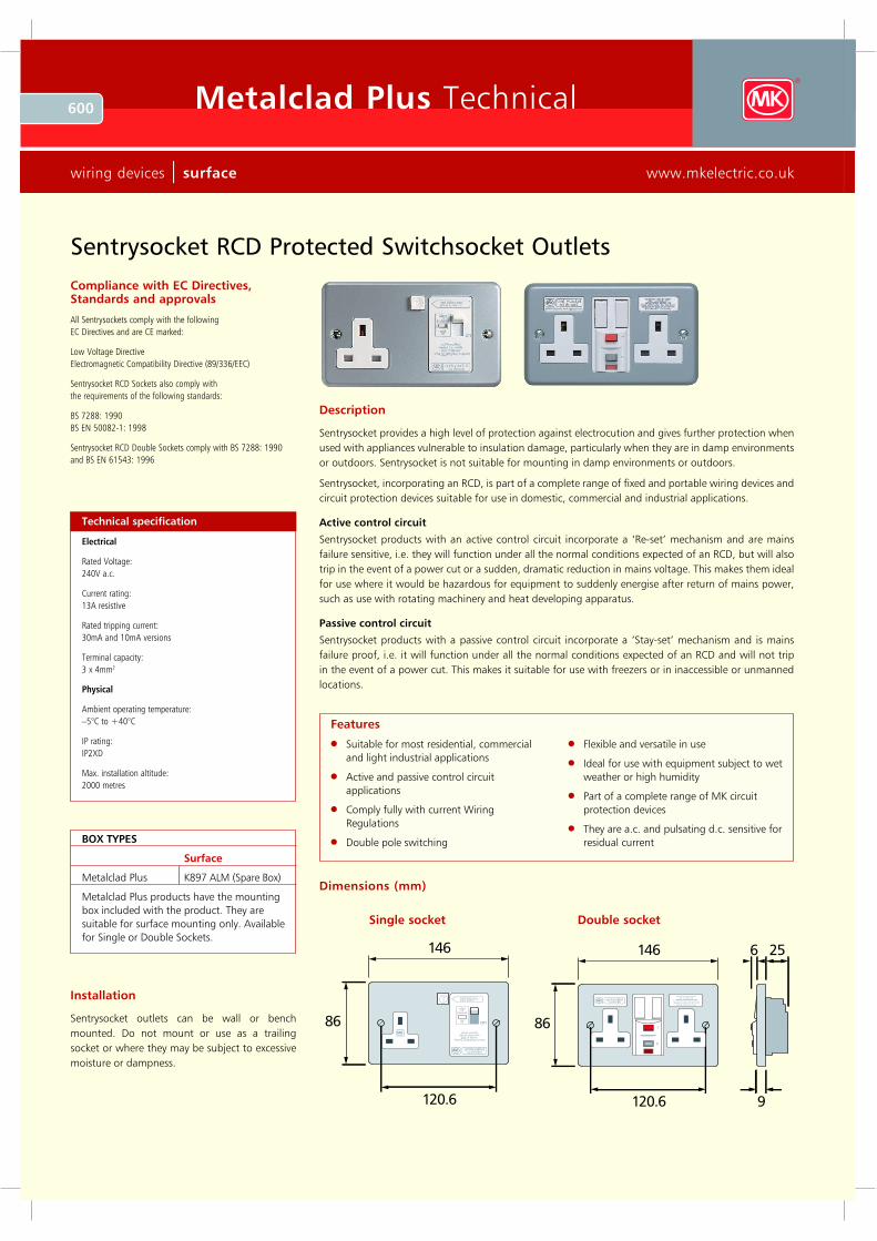
Sen trysocket RC D P rotected Sw itch socket Outlets
C ompliance with EC Directiv es, Standards and approv als
All Sentrysockets comply with the following
E C Directives and are CE marked:
Low Voltage Directive
E lectromagnetic Compatibility Directive (89 /336/E E C)
Sentrysocket R CD Sockets also comply with
the req uirements of the following standards:
BS 7 288: 19 9 0
BS E N 50082-1: 19 9 8
Sentrysocket R CD Double Sockets comply with BS 7 288: 19 9 0
and BS E N 61543: 19 9 6
Description
Sentrysocket provides a high level of protection against electrocution and gives further protection when
used with appliances vulnerable to insulation damage, particularly when they are in damp environments
or outdoors. Sentrysocket is not suitable for mounting in damp environments or outdoors.
Sentrysocket, incorporating an R CD, is part of a complete range of fixed and portable wiring devices and
circuit protection devices suitable for use in domestic, commercial and industrial applications.
A ctiv e control circuit
Sentrysocket products with an active control circuit incorporate a ‘R e-set’ mechanism and are mains
failure sensitive, i.e. they will function under all the normal conditions expected of an R CD, but will also
trip in the event of a power cut or a sudden, dramatic reduction in mains voltage. This makes them ideal
for use where it would be hazardous for equipment to suddenly energise after return of mains power,
such as use with rotating machinery and heat developing apparatus.
Passiv e control circuit
Sentrysocket products with a passive control circuit incorporate a ‘Stay-set’ mechanism and is mains
failure proof, i.e. it will function under all the normal conditions expected of an R CD and will not trip
in the event of a power cut. This makes it suitable for use with freezers or in inaccessible or unmanned
locations.
Technical specification
Electrical
R ated Voltage:
240V a.c.
Current rating:
13A resistive
R ated tripping current:
30mA and 10mA versions
Terminal capacity:
3 x 4mm2
Physical
Ambient operating temperature:
–5°C to +40°C
IP rating:
IP2XD
Max. installation altitude:
2000 metres
Suitable for most residential, commercial
and light industrial applications
A ctive and passive control circuit
applications
Comply fully with current W iring
R egulations
Double pole switching
F lexible and versatile in use
Ideal for use with equipment subject to wet
weather or high humidity
Part of a complete range of MK circuit
protection devices
They are a.c. and pulsating d.c. sensitive for
residual current
Features
146
86
120.6
TT test b efore usepress b utton - T
w h iteoff
(tripped)
redon on
activ e con troldev ice trips w ith
loss of m ain s10m A trippin g curren t
sen trysocketrcd protected
146 25
86
120.6 9
6
sen trysocketrcd protected
T
R
F lag b elow Reset (R) b utton .Red : ON B lack: OF F
ALWAYS TEST BEFORE USE
P ress Test (T) b utton , Red flag sh oulddisappear. If it does n ot, do n ot use.
P ress Reset (R) after testin g .
Dimensions (mm)
Doub le sock etSingle sock et
BOX TYPES
Surface
Metalclad Plus K89 7 A LM (Spare Box)
Metalclad Plus products have the mounting
box included with the product. They are
suitable for surface mounting only. A vailable
for Single or Double Sockets.
Installation
Sentrysocket outlets can be wall or bench
mounted. Do not mount or use as a trailing
socket or where they may be subject to excessive
moisture or dampness.
601Metalclad Plus Technical
technical hotline + 4 4 (0 )1268 5 63720 surface | wiring devices
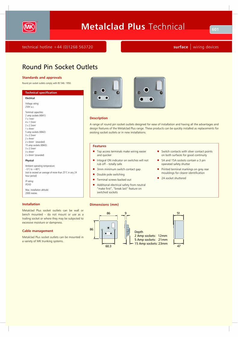
Round Pin Socket Outlets
Standards and approvals
Round pin socket outlets comply with BS 546: 1950.
Description
A range of round pin socket outlets designed for ease of installation and having all the advantages and
design features of the Metalclad Plus range. These products can be quickly installed as replacements for
existing socket outlets or in new installations.
Installation
Metalclad Plus socket outlets can be wall or
bench mounted – do not mount or use as a
trailing socket or where they may be subjected to
excessive moisture or dampness.
Technical specification
Electrical
Voltage rating:
250V a.c.
Terminal capacities:
2 amp sockets (K841):
7 x 1mm2
4 x 1.5mm2
2 x 2.5mm2
1 x 4mm2
5 amp sockets (K842):
3 x 2.5mm2
2 x 4mm2
2 x 6mm2 (stranded)
15 amp sockets (K843):
3 x 2.5mm2
3 x 4mm2
2 x 6mm2 (stranded)
Physical
Ambient operating temperature:
–5°C to +40°C
(not to exceed an average of more than 25°C in any 24
hour period)
IP rating:
IP2XD
Max. installation altitude:
2000 metres
Top access terminals make wiring easier
and quicker
Integral ON indicator on switches will not
rub off – totally safe
3mm minimum switch contact gap
Double pole switching
Terminal screws backed out
Additional electrical safety from neutral
“ make first” , “ break last” feature on
switched sockets
Switch contacts with silver contact points
on both surfaces for good continuity
5 A and 15 A sockets contain a 3 pin
operated safety shutter
Printed terminal markings on grey rear
mouldings for clearer identification
2A socket shuttered
Features
Cable management
Metalclad Plus socket outlets can be mounted in
a variety of MK trunking systems.
86
86
60 .3
D e p th
2 A m p s o c k e ts : 1 2 m m
5 A m p s o c k e ts : 2 1 m m
1 5 A m p s o c k e ts : 2 3 m m
5 1
4 7
9
Dimensions (mm)
602 Metalclad Plus Technical
wiring devices | surface www.mkelectric.co.uk
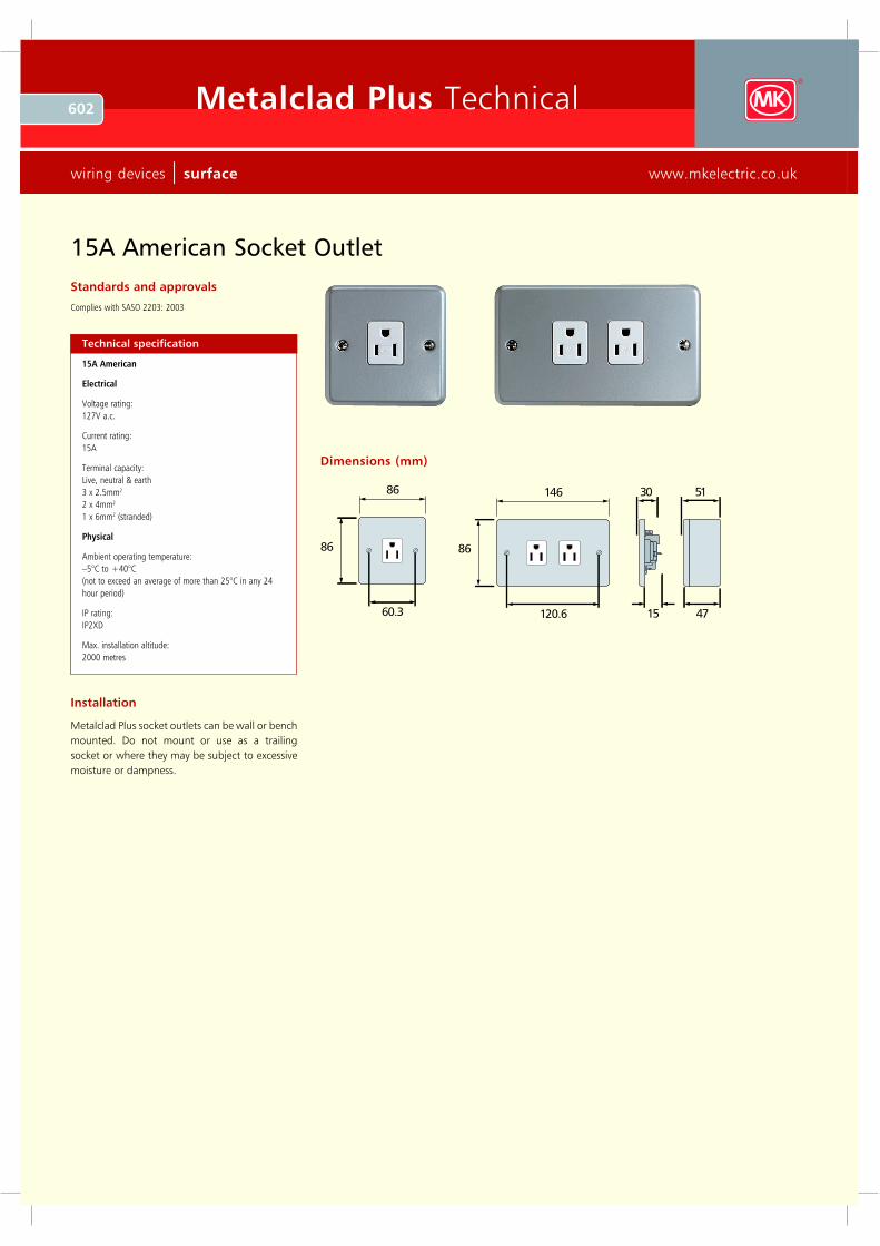
Standards and approvals
Complies with SASO 2203: 2003
Technical specification
15A American
Electrical
Voltage rating:
127V a.c.
Current rating:
15A
Terminal capacity:
Live, neutral & earth
3 x 2.5mm2
2 x 4mm2
1 x 6mm2 (stranded)
Physical
Ambient operating temperature:
–5°C to +40°C
(not to exceed an average of more than 25°C in any 24
hour period)
IP rating:
IP2XD
Max. installation altitude:
2000 metres
86
86
60 .3
14 6
8 6
12 0 .6
3 0
15
5 1
4 7
15A American Socket Outlet
Dimensions (mm)
Installation
Metalclad Plus socket outlets can be wall or bench
mounted. Do not mount or use as a trailing
socket or where they may be subject to excessive
moisture or dampness.
603Metalclad Plus Technical
technical hotline +44 (0)1268 563720 surface | wiring devices
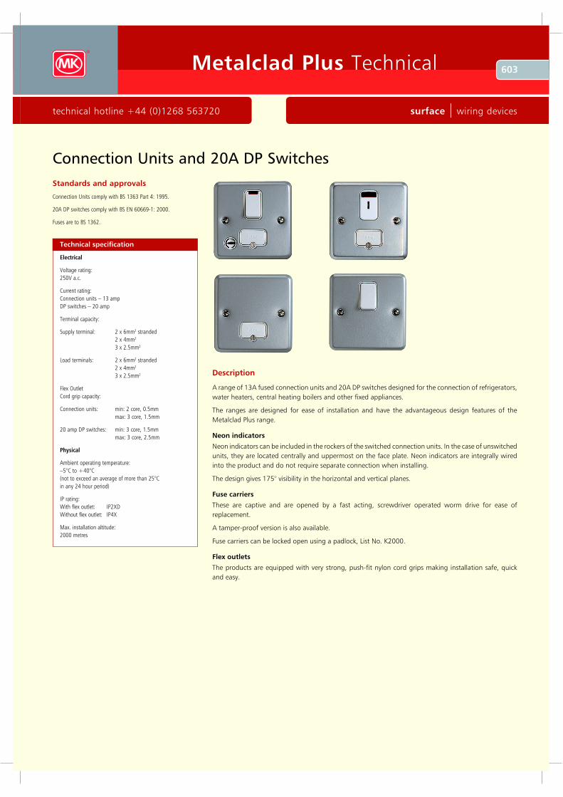
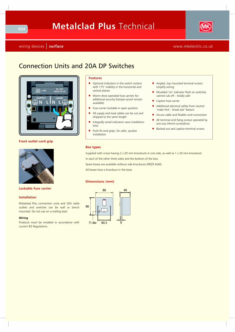
Connection U nits and 20A DP Switches
Standards and approvals
Connection Units comply with BS 1363 Part 4: 1995.
20A DP switches comply with BS EN 60669-1: 2000.
F uses are to BS 1362.
Description
A range of 13A fused connection units and 20A DP switches designed for the connection of refrigerators,
water heaters, central heating boilers and other fixed appliances.
The ranges are designed for ease of installation and have the advantageous design features of the
Metalclad Plus range.
N eon indicators
Neon indicators can be included in the rockers of the switched connection units. In the case of unswitched
units, they are located centrally and uppermost on the face plate. Neon indicators are integrally wired
into the product and do not require separate connection when installing.
The design gives 175° visibility in the horizontal and vertical planes.
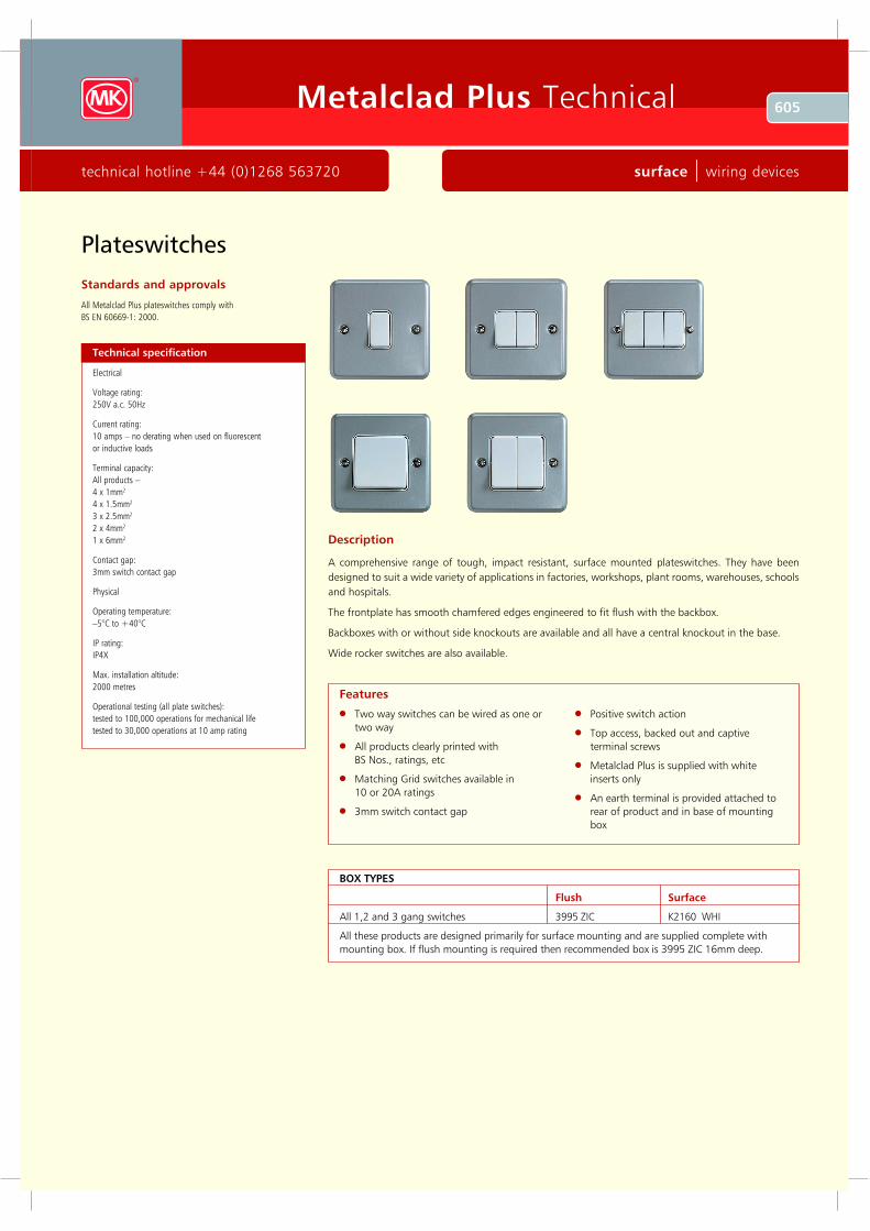
Fuse carriers
These are captive and are opened by a fast acting, screwdriver operated worm drive for ease of
replacement.
A tamper-proof version is also available.
Fuse carriers can be locked open using a padlock, List No. K2000.
Flex outlets
The products are equipped with very strong, push-fit nylon cord grips making installation safe, quick
and easy.
Technical specification
Electrical
Voltage rating:
250V a.c.
Current rating:
Connection units – 13 amp
DP switches – 20 amp
Terminal capacity:
Supply terminal: 2 x 6mm2 stranded
2 x 4mm2
3 x 2.5mm2
Load terminals: 2 x 6mm2 stranded
2 x 4mm2
3 x 2.5mm2
F lex Outlet
Cord grip capacity:
Connection units: min: 2 core, 0.5mm
max: 3 core, 1.5mm
20 amp DP switches: min: 3 core, 1.5mm
max: 3 core, 2.5mm
Physical
Ambient operating temperature:
–5°C to +40°C
(not to exceed an average of more than 25°C
in any 24 hour period)
IP rating:
W ith flex outlet: IP2XD
W ithout flex outlet: IP4X
Max. installation altitude:
2000 metres
604 Metalclad Plus Technical
wiring devices | surface www.mkelectric.co.uk
Optional indicators in the switch rockers
with 175° visibility in the horizontal and
vertical planes
Worm-drive operated fuse carriers for
additional security (tamper-proof version
available)
Fuse carrier lockable in open position
All supply and load cables can be cut and
stripped to the same length
Integrally wired indicators save installation
time
Push-fit cord grips, for safer, quicker
installation
Angled, top mounted terminal screws
simplify wiring
Moulded ‘on’ indicator flash on switches
cannot rub off – totally safe
Captive fuse carrier
Additional electrical safety from neutral
‘make first’, ‘break last’ feature
Secure cable and flexible cord connection
All terminal and fixing screws operated by
one-size (4mm) screwdriver
Backed out and captive terminal screws
Features
Front outlet cord grip
L ockable fuse carrier
Installation
Metalclad Plus connection units and 20A cable
outlets and switches can be wall or bench
mounted. Do not use on a trailing lead.
W iring
Products must be installed in accordance with
current IEE Regulations.
Box ty pes
Supplied with a box having 2 x 20 mm knockouts in one side, as well as 1 x 20 mm knockouts
in each of the other three sides and the bottom of the box.
Spare boxes are available without side knockouts (K829 ALM).
All boxes have a knockout in the base.
Dimensions (mm)
86 49
86
60.311 dia
fusefuse
9
Connection Units and 20A DP Switches
605Metalclad Plus Technical
technical hotline +44 (0)1268 563720 surface | wiring devices
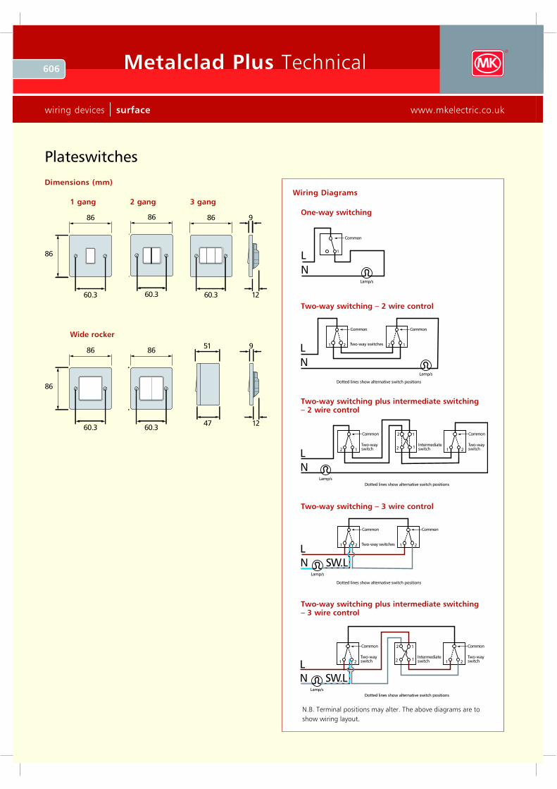
Plateswitches
Standards and approvals
All Metalclad Plus plateswitches comply with
BS EN 60669-1: 2000.
Technical specification
Electrical
Voltage rating:
250V a.c. 50H z
Current rating:
10 amps – no derating when used on fluorescent
or inductive loads
Terminal capacity:
All products –
4 x 1mm2
4 x 1.5mm2
3 x 2.5mm2
2 x 4mm2
1 x 6mm2
Contact gap:
3mm switch contact gap
Physical
Operating temperature:
–5°C to +40°C
IP rating:
IP4X
Max. installation altitude:
2000 metres
Operational testing (all plate switches):
tested to 100,000 operations for mechanical life
tested to 30,000 operations at 10 amp rating
Description
A comprehensive range of tough, impact resistant, surface mounted plateswitches. They have been
designed to suit a wide variety of applications in factories, workshops, plant rooms, warehouses, schools
and hospitals.
The frontplate has smooth chamfered edges engineered to fit flush with the backbox.
Backboxes with or without side knockouts are available and all have a central knockout in the base.
Wide rocker switches are also available.
Two way switches can be wired as one or
two way
All products clearly printed with
BS Nos., ratings, etc
Matching G rid switches available in
10 or 20A ratings
3mm switch contact gap
Positive switch action
Top access, backed out and captive
terminal screws
Metalclad Plus is supplied with white
inserts only
An earth terminal is provided attached to
rear of product and in base of mounting
box
Features
BOX TYPES
Flush Surface
All 1,2 and 3 gang switches 3995 ZIC K2160 WH I
All these products are designed primarily for surface mounting and are supplied complete with
mounting box. If flush mounting is required then recommended box is 3995 ZIC 16mm deep.
606 Metalclad Plus Technical
wiring devices | surface www.mkelectric.co.uk
Plateswitches
86
86
60.3
Dimensions (mm)
1 gang
86
86
60.3
86
60.347
51
12
9
Wide rocker
86
60.3
86
60.3 12
9
2 gang 3 gangWiring Diagrams
One-way switching
N
L1
Common
Lamp/s
Two-way switching – 2 wire control
N
L
Lamp/s
21
Common
12
Common
Two-way switches
Dotted lines show alternative switch positions
Two-way switching – 3 wire control
NL
21
Common
21
Common
Two-way switches
Dotted lines show alternative switch positions
Lamp/s
SW .L
Two-way switching plus intermediate switching – 2 wire control
NL
12
Common
21
Common
Two-wayswitch
Two-wayswitch
Dotted lines show alternative switch positions
Lamp/s
1
1
2
2Intermediateswitch
Two-way switching plus intermediate switching – 3 wire control
L
1
1
2
221
Common
21
Common
Two-wayswitch
Two-wayswitch
Dotted lines show alternative switch positions
Intermediateswitch
NLamp/s
SW .L
N.B. Terminal positions may alter. The above diagrams are to
show wiring layout.
607Metalclad Plus Technical
technical hotline +44 (0)1268 563720 surface | wiring devices
Standards and approvals
All DP switches in the range conform to
BS EN 60669-1: 2000.
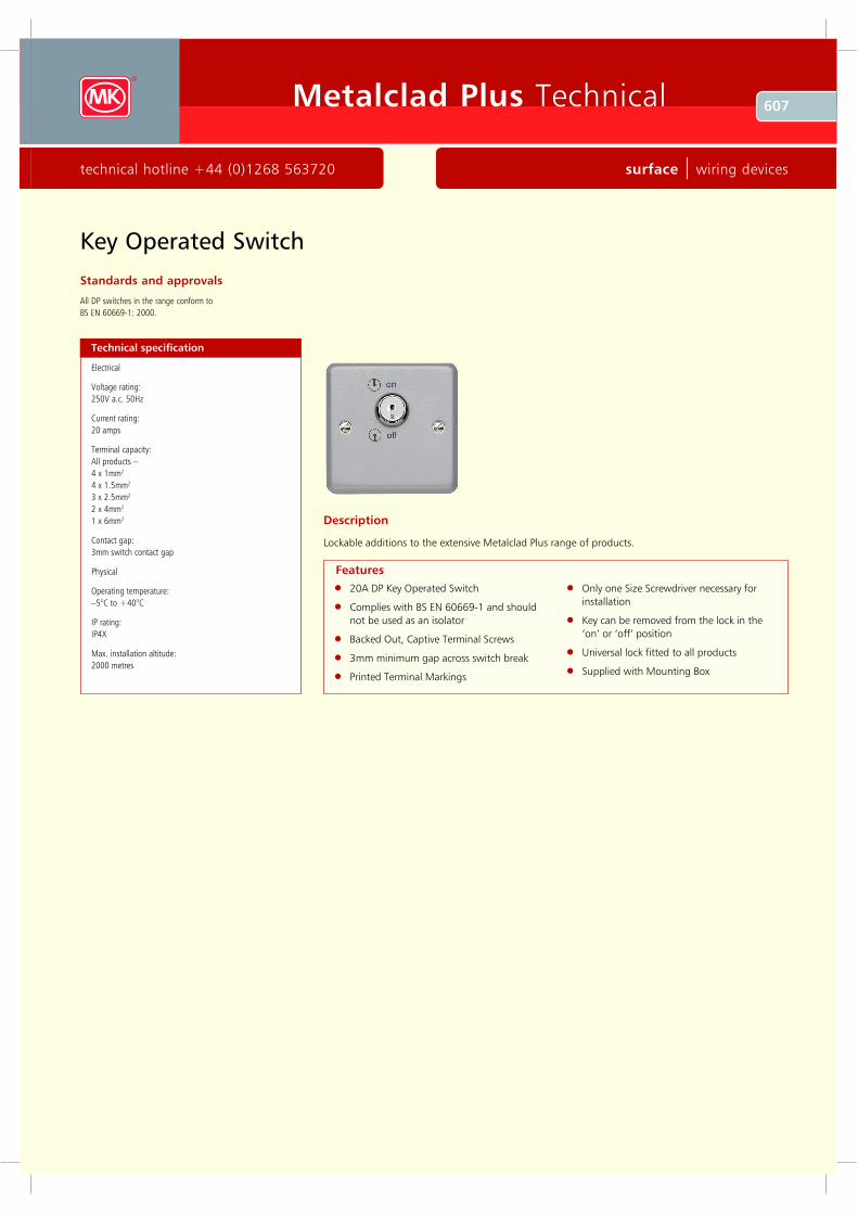
Key Operated Switch
Description
Lockable additions to the extensive Metalclad Plus range of products.
20A DP Key Operated Switch
Complies with BS EN 60669-1 and should
not be used as an isolator
Backed Out, Captive Terminal Screws
3mm minimum gap across switch break
Printed Terminal Markings
Only one Size Screwdriver necessary for
installation
Key can be removed from the lock in the
‘on’ or ‘off’ position
Universal lock fitted to all products
Supplied with Mounting Box
Technical specification
Electrical
Voltage rating:
250V a.c. 50Hz
Current rating:
20 amps
Terminal capacity:
All products –
4 x 1mm2
4 x 1.5mm2
3 x 2.5mm2
2 x 4mm2
1 x 6mm2
Contact gap:
3mm switch contact gap
Physical
Operating temperature:
–5°C to +40°C
IP rating:
IP4X
Max. installation altitude:
2000 metres
Features
608 Metalclad Plus Technical
wiring devices | surface www.mkelectric.co.uk
Standards and approvals
All DP switches in the range conform to
BS EN 60669-1: 2000.
H igh Current Switches
Technical specification
Electrical
Voltage rating:
250V a.c.
Current:
32/50A resistive
Switch:
3mm contact gap
Double pole operation
Terminal capacity, 45A Switches
4 x 4mm2
3 x 6mm2
1 x 16mm2
Terminal capacity, 32A Switch:
3 x 2.5mm2
2 x 4mm2
1 x 6mm2
Physical
Ambient operating temperature:
–5°C to +40°C
(not to exceed an average of more than 25°C in any 24
hour period)
IP rating:
IP4X
Max. installation altitude:
2000 metres
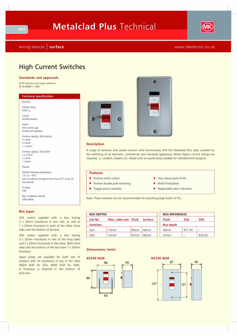
Description
A range of switches and cooker control units harmonising with the Metalclad Plus style, suitable for
the switching of all domestic, commercial and industrial appliances where higher current ratings are
required, i.e. cookers, heaters etc. Metal units are particularly suitable for refurbishment projects.
Positive switch action
Positive double pole switching
Toggle action switches
V ery robust paint finish
Metal frontplates
Replaceable neon indicators
Features
Note: These switches are not recommended for switching large banks of PCs
Box types
32A switch supplied with a box having
2 x 20mm knockouts in one side, as well as
1 x 20mm knockout in each of the other three
sides and the bottom of the box.
50A switch supplied with a box having
3 x 20mm knockouts in one of the long sides
and 2 x 20mm knockouts in the other. Both short
sides and the bottom of the box have 1 x 20mm
knockout.
Spare boxes are available for both size of
product with no knockouts in any of the sides
(K829 ALM for 32A, K830 ALM for 50A).
A knockout is retained in the bottom of
each box.
86
86
60
49
off
on
Dimensions (mm)
147 121
87 49
off
on
K 5240 ALM K 5230 ALM
BOX DEPTH S
List No. Max. cable siz e Flush Surface
Switches
32A 10mm2 46mm 40mm
50A 10mm2 47mm 40mm
BOX R EFER ENCES
Flush 32A 50A
Box depth
46mm 877 ZIC –
47mm – 878 ZIC
609Metalclad Plus Technical
technical hotline +44 (0)1268 563720 surface | wiring devices
Standards and approvals
Comply with BS EN 60947: 1992.
Technical specification
Electrical
Voltage rating:
250V a.c. 50Hz
Current rating:
10 amps
Terminal capacity:
4 x 1mm2
4 x 1.5mm2
3 x 2.5mm2
2 x 4mm2
1 x 6mm2
Contact gap:
3mm switch contact gap
Classifications
Method of operation: Stored energy operation
Suitability for isolation: Suitable for isolation
Ratings
Utilisation category AC23B
Rated operational voltage (Ue) 250V
Conventional free air thermal
current (Ith) 10A
Rated frequency 50Hz
Rated making capacity 100A rms
Rated breaking capacity 80A rms
Rated conditional short-circuit
current 6000A rms
(with supply side protective device G EC NIT 16
BS88: part 2: 1988 16A 550VAC utilisation
category gG 80KA breaking capacity fuse links.)
Physical
Operating temperature:
–5°C to +40°C
IP rating:
IP4X
Max. installation altitude:
2000 metres
Switchlock list no. K4858 is available to
allow the isolator to be locked in the
disconnected position to facilitate fan
maintenance
Features
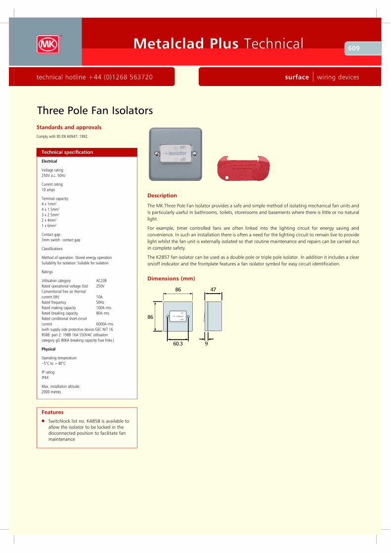
Description
The MK Three Pole Fan Isolator provides a safe and simple method of isolating mechanical fan units and
is particularly useful in bathrooms, toilets, storerooms and basements where there is little or no natural
light.
For example, timer controlled fans are often linked into the lighting circuit for energy saving and
convenience. In such an installation there is often a need for the lighting circuit to remain live to provide
light whilst the fan unit is externally isolated so that routine maintenance and repairs can be carried out
in complete safety.
The K2857 fan isolator can be used as a double pole or triple pole isolator. In addition it includes a clear
on/off indicator and the frontplate features a fan isolator symbol for easy circuit identification.
86
86
60 .3
o n
o ff
is o la to r
4 7
9
Dimensions (mm)
Three Pole Fan Isolators
610 Metalclad Plus Technical
wiring devices | surface www.mkelectric.co.uk
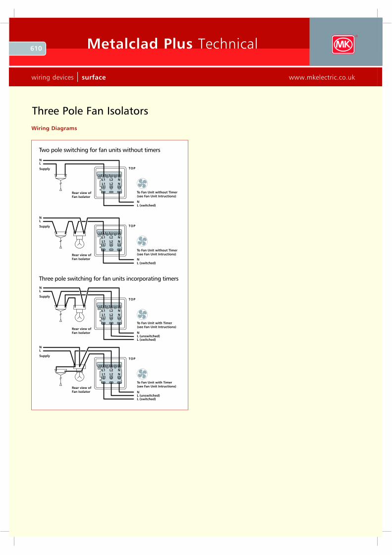
Three Pole Fan Isolators
L2L1 N
L2L1 N
N
Rear view ofFan Isolator
Rear view ofFan Isolator
Rear view ofFan Isolator
Rear view ofFan Isolator
L (switched)
NL
Supply
L2L1 N
L2L1 N
NL (unswitched)
To Fan U nit with Timer(see Fan U nit Intructions)
L (switched)
NL
Supply
L2L1 N
L2L1 N
NL (unswitched)
To Fan U nit with Timer(see Fan U nit Intructions)
L (switched)
NL
Supply
L2L1 N
L2L1 N
N
To Fan U nit without Timer(see Fan U nit Intructions)
To Fan U nit without Timer(see Fan U nit Intructions)
L (switched)
NL
Supply
Three pole switching for fan units incorporating timers
Two pole switching for fan units without timers
TOP
TOP
TOP
TOP
Wiring Diagrams
611Metalclad Plus Technical
technical hotline +44 (0)1268 563720 surface | wiring devices
E uro and LJU6C Data Frontplates
1G and 2G frontplates
Metalclad Plus style
Accept industry standard Euro or LJU6C
snapfit modules
K181 Euro frontplate accepts 1 Euro
module, (25 x 50mm aperture)
K182 Euro frontplate accepts 2 Euro
modules, (50 x 50mm aperture)
K184 Euro frontplate accepts 4 Euro
modules, (100 x 50mm aperture)
K172 LJU6C frontplate accepts two
LJU6C modules (27 x 37mm apertures)
1⁄2 module (12.5 x 50mm) blank
available for Euro frontplates
Interchangeable modules clip into
frontplate
Features
Standards and approvals
BS 5733: 1995
Technical specification
Dimensions
Height: 86mm
Width: 86mm (1G)
146mm (2G)
Depth: 9mm
Ap ertu re Dimensions (N ominal)
Euro Frontplates
Height: 50mm
Width: 50mm (1G)
100mm (2G)
LJU6C Frontplates
Height: 37mm
Width: 22mm
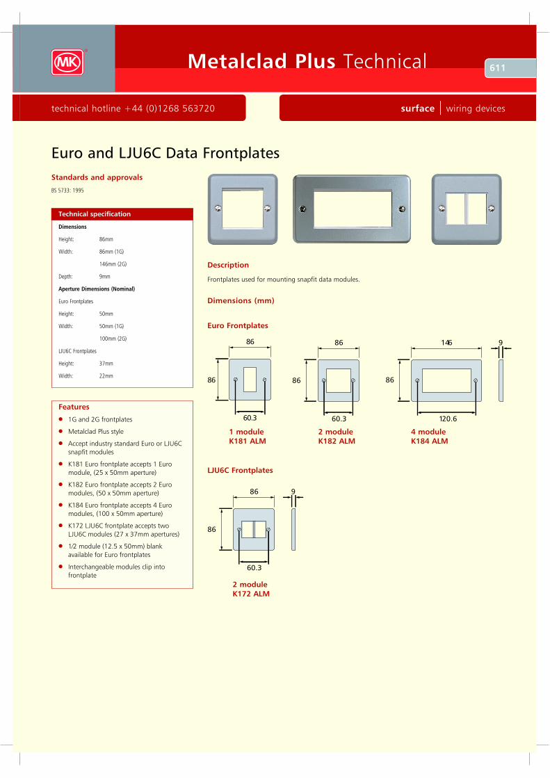
Description
Frontplates used for mounting snapfit data modules.
Dimensions (mm)
Euro Frontplates
86
86
60 .3
1 module
K181 ALM
LJU6C Frontplates
4 module
K184 ALM
2 module
K172 ALM
2 module
K182 ALM
612 Metalclad Plus Technical
wiring devices | surface www.mkelectric.co.uk
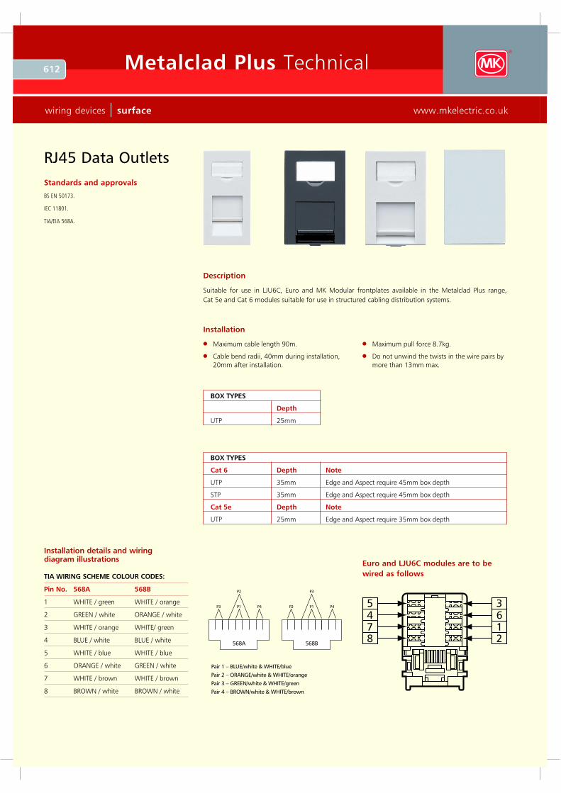
RJ45 Data Outlets
Standards and approvals
BS EN 50173.
IEC 11801.
TIA/EIA 568A.
Description
Suitable for use in LJU6C, Euro and MK Modular frontplates available in the Metalclad Plus range,
Cat 5e and Cat 6 modules suitable for use in structured cabling distribution systems.
Installation
Maximum cable length 90m.
Cable bend radii, 40mm during installation,
20mm after installation.
Maximum pull force 8.7kg.
Do not unwind the twists in the wire pairs by
more than 13mm max.
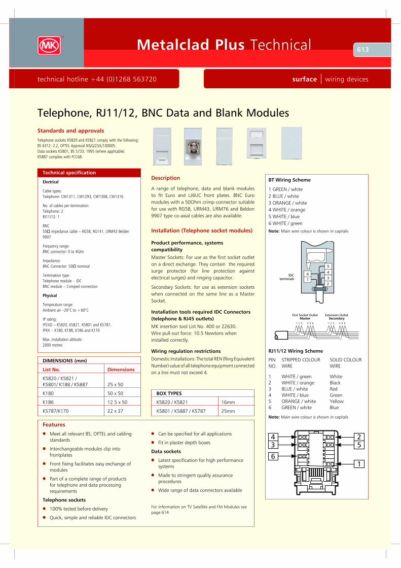
P3 P1
P2
P4
568A
P2 P1
P3
P4
568B
Pair 1 – BLUE/white & WHITE/blue
Pair 2 – ORANG E/white & WHITE/orange
Pair 3 – G REEN/white & WHITE/green
Pair 4 – BROWN/white & WHITE/brown
5
4
7
8
3
6
1
2
Euro and LJU6C modules are to be
wired as follows
Installation details and wiring diagram illustrations
TIA WIRING SCHEME COLOUR CODES:
Pin No. 568A 568B
1 WHITE / green WHITE / orange
2 GREEN / white ORANGE / white
3 WHITE / orange WHITE/ green
4 BLUE / white BLUE / white
5 WHITE / blue WHITE / blue
6 ORANGE / white GREEN / white
7 WHITE / brown WHITE / brown
8 BROWN / white BROWN / white
BOX TYPES
Depth
UTP 25mm
BOX TYPES
Cat 6 Depth Note
UTP 35mm Edge and Aspect require 45mm box depth
STP 35mm Edge and Aspect require 45mm box depth
Cat 5e Depth Note
UTP 25mm Edge and Aspect require 35mm box depth
613Metalclad Plus Technical
technical hotline +44 (0)1268 563720 surface | wiring devices
Telephone, RJ11/12, BNC Data and Blank M odules
Installation (Telephone socket modules)
Product performance, systems
compatibility
Master Sockets: For use as the first socket outlet
on a direct exchange. They contain the required
surge protector (for line protection against
electrical surges) and ringing capacitor.
Secondary Sockets: for use as extension sockets
when connected on the same line as a Master
Socket.
Installation tools req uired IDC Connectors
(telephone & RJ45 outlets)
MK insertion tool List No. 400 or 22630.
Wire pull-out force: 10.5 Newtons when
installed correctly.
Wiring regulation restrictions
Domestic Installations: The total REN (Ring Equivalent
Number) value of all telephone equipment connected
on a line must not exceed 4.
Standards and approvals
Telephone sockets K5820 and K5821 comply with the following:
BS 6312: 2.2, OFTEL Approval NS/G/23/L/100005.
Data sockets K5801, BS 5733: 1995 (where applicable).
K5887 complies with FCC68.
Technical specification
Electrical
Cable types:
Telephone: CW1311, CW1293, CW1308, CW1316
No. of cables per termination:
Telephone: 2
RJ11/12: 1
BNC
50 impedance cable – RG58, RG141, URM43 Belden
9907
Frequency range:
BNC connector: 0 to 4GHz
Impedance:
BNC Connector: 50 nominal
Termination type:
Telephone module – IDC
BNC module – Crimped connection
Physical
Temperature range:
Ambient air –20°C to +60°C
IP rating:
IP2XD – K5820, K5821, K5801 and K5787.
IP4X – K180, K188, K186 and K170
Max. installation altitude:
2000 metres
Meet all relevant BS, OFTEL and cabling
standards
Interchangeable modules clip into
frontplates
Front fixing facilitates easy exchange of
modules
Part of a complete range of products
for telephone and data processing
requirements
Telephone sockets
100% tested before delivery
Q uick, simple and reliable IDC connectors
Can be specified for all applications
Fit in plaster depth boxes
Data sockets
Latest specification for high performance
systems
Made to stringent quality assurance
procedures
Wide range of data connectors available
For information on TV Satellite and FM Modules see
page 614
Features
Description
A range of telephone, data and blank modules
to fit Euro and LJ6UC front plates. BNC Euro
modules with a 50Ohm crimp connector suitable
for use with RG58, URM43, URM76 and Beldon
9907 type co-axial cables are also available.
IDC
terminals 1
6
5
3
4
2
1 2 3 4 5 6 1 2 3 4 5 6
F irs t S o c k e t O u tle t
MasterE x te n s io n O u tle t
Sec o n d ary
BT W irin g Sc h em e
1 GR E E N / w h ite
2 B L U E / w h ite
3 OR A NGE / w h ite
4 W H IT E / o ra n g e
5 W H IT E / b lu e
6 W H IT E / g re e n
No te: M a in w ire c o lo u r is s h o w n in c a p ita ls
RJ1 1 /1 2 W irin g Sc h em e
PIN ST R IPPE D C OL OU R SOL ID C OL OU R
NO. W IR E W IR E
1 W H IT E / g re e n W h ite
2 W H IT E / o ra n g e B la c k
3 B L U E / w h ite R e d
4 W H IT E / b lu e Gre e n
5 OR A NGE / w h ite Y e llo w
6 GR E E N / w h ite B lu e
No te: M a in w ire c o lo u r is s h o w n in c a p ita ls
4
3
6
2
5
1
D IMENSIONS (m m )
L ist No . D im en sio n s
K 58 20 / K 58 21 /
K 58 0 1/ K 18 8 / K 58 8 7 25 x 50
K 18 0 50 x 50
K 18 6 12.5 x 50
K 57 8 7 /K 17 0 22 x 37
BOX TYPES
K 58 20 / K 58 21 16m m
K 58 0 1 / K 58 8 7 / K 57 8 7 25m m
614 Metalclad Plu s Technical
wiring dev ices | su rface www.mkelectric.co.uk
Standards and ap p rov als
All MK Digital TV Outlets comply with BS 5733
an d BS E N 50 0 8 3 where applicab le.
Also IE C 1 6 9 -2 , BS E N 6 0 1 6 9 -2 4 an d BS 6 31 2 P art 2 .
Mod ular prod ucts are E uro compatib le.
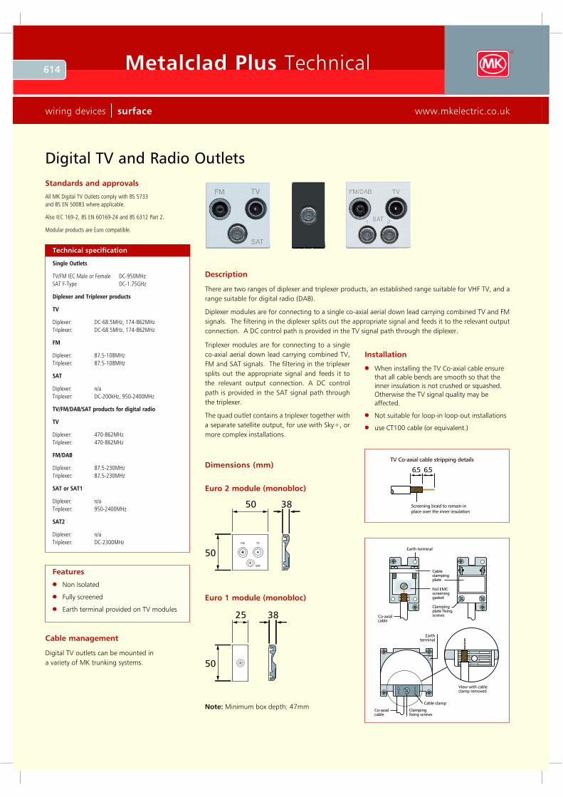
D ig ita l T V a nd R a d io Outlets
Installation
When installing the TV Co-axial cable ensure
that all cable bends are smooth so that the
inner insulation is not crushed or sq uashed.
Otherwise the TV signal q uality may be
affected.
Not suitable for loop-in loop-out installations
use CT100 cable (or eq uiv alent.)
Dimensions (mm)6.5
Screening b ra id to rem a in inp la ce ov er th e inner insula tion
6.5
T V C o-a xia l ca b le strip p ing d eta ils
Ea rth term ina l
C o-a xia lca b le
Foil EM Cscreeningg a sket
C la m p ingp la te fixingscrew s
C a b lecla m p ingp la te
Ea rthterm ina l
C la m p ingfixing screw s
V iew w ith ca b lecla m p rem ov ed
C a b le cla m p
C o-a xia lca b le
Descrip tion
There are two ranges of diplexer and triplexer products, an established range suitable for V HF TV , and a
range suitable for digital radio (DAB).
Diplexer modules are for connecting to a single co-axial aerial down lead carry ing combined TV and F M
signals. The filtering in the diplexer splits out the appropriate signal and feeds it to the relev ant output
connection. A DC control path is prov ided in the TV signal path through the diplexer.
Non Isolated
F ully screened
Earth terminal prov ided on TV modules
F eatu res
C ab le management
Digital TV outlets can be mounted in
a v ariety of MK trunking sy stems.
Eu ro 2 modu le (monob loc)
Eu ro 1 modu le (monob loc)
Note: Minimum box depth: 47mm
Technical sp ecif ication
Single Outlets
TV/F M IE C Male or F emale DC -9 50 MH z
SAT F -Type DC -1 .75G H z
D ip lex er a nd T rip lex er p ro d uc ts
T V
Diplex er: DC -6 8 .5MH z , 1 74 -8 6 2 MH z
Triplex er: DC -6 8 .5MH z , 1 74 -8 6 2 MH z
F M
Diplex er: 8 7.5-1 0 8 MH z
Triplex er: 8 7.5-1 0 8 MH z
SA T
Diplex er: n /a
Triplex er: DC -2 0 0 k H z , 9 50 -2 4 0 0 MH z
T V /F M /D A B /SA T p ro d uc ts fo r d igita l ra d io
T V
Diplex er: 4 70 -8 6 2 MH z
Triplex er: 4 70 -8 6 2 MH z
F M /D A B
Diplex er: 8 7.5-2 30 MH z
Triplex er: 8 7.5-2 30 MH z
SA T o r SA T 1
Diplex er: n /a
Triplex er: 9 50 -2 4 0 0 MH z
SA T 2
Diplex er: n /a
Triplex er: DC -2 30 0 MH z
Triplexer modules are for connecting to a single
co-axial aerial down lead carry ing combined TV ,
F M and SAT signals. The filtering in the triplexer
splits out the appropriate signal and feeds it to
the relev ant output connection. A DC control
path is prov ided in the SAT signal path through
the triplexer.
The q uad outlet contains a triplexer together with
a separate satellite output, for use with Sky + , or
more complex installations.
615Metalclad Plus Technical
technical hotline +44 (0)1268 563720 surface | wiring devices
Installation (TV sock ets)
Product performance, systems compatibility
Isolated Outlets are intended for use where safety isolation (rated at 2000V
ac) is required to provide protection against faults occurring within any mains
powered product used on different parts of the distribution system. They are
not suitable for use in systems where DC signals are passed through the
socket, (e.g. where masthead/headend equipment is controlled by receiver/
decoder equipment).
Diplexer Outlets are used in distribution systems where both TV and FM
band signals are combined on a single aerial downlead. The filtering in the
diplexer separates the appropriate signals and feeds them through to the
relevant output connection port.
Cable Routing and U se of Cable Clamp
Sharp bends in the cable must be avoided during installation. The single TV/
FM socket is fitted with a cable clamp that can be fixed on either side of the
termination position to facilitate this.
When tightening the screening braid clamps ensure that the cable is firmly
gripped and that the inner insulation is not squashed flat beyond a slight
oval shape.
Safety Information
TV outlets or modules must not be installed in the same enclosure as equipment
rated in excess of 50V, (e.g. mains rated 13A sockets or switches).
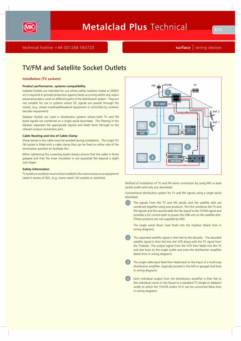
TV/FM and Satellite Socket Outlets
Method of installation of TV and FM aerial connection by using MK co-axial
socket outlet and only one downlead.
Conventional distribution system for TV and FM signals using a single aerial
downlead.
The signals from the TV and FM aerials and the satellite dish are
combined together using two products. The first combines the TV and
FM signals and the second adds the Sky signal to the TV/FM signal and
provides a DC control path to power the LNB unit on the satellite dish.
(These products are not supplied by MK).
The single aerial down lead feeds into the triplexer (black lines in
wiring diagram).
The separated satellite signal is then fed to the decoder. The decoded
satellite signal is then fed into the VCR along with the TV signal from
the Triplexer. The output signal from the VCR then feeds into the TV
and also back to the single outlet and onto the distribution amplifier
(black lines in wiring diagram).
The single cable back-feed then feeds back to the input of a multi way
distribution amplifier, (typically located in the loft or garage) (red lines
in wiring diagram).
Each individual output from the distribution amplifier is then fed to
the individual rooms in the house to a standard TV (single or diplexer)
outlet to which the TV/VCR and/or Hi-Fi can be connected (blue lines
in wiring diagram).
1
2
3
4
FM T V
S A T 1
D A B
TV
TV
TV
TV
VID
S K Y /D IG
VID
TV D IS T
H I-F I
S A T 2
1
4
4
4
2
3
616 Metalclad Plus Technical
wiring devices | surface www.mkelectric.co.uk
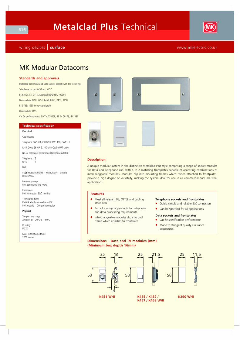
25 1 3
58
1 4
Dimensions – Data and TV modules (mm)
(Minimum box depth 16mm)
K 451 WHI K 455 / K 452 / K 457 / K 458 WHI
K 29 0 WHI
Standards and approvals
Metalclad Telephone and Data sockets comply with the following:
Telephone sockets K452 and K457
BS 6312: 2.2, OFTEL Approv al NS/G/23/L /100005
Data sockets K290, K451, K452, K455, K457, K458
BS 5733: 1995 (where applicable)
Data sockets K455
Cat 5e performance to EIA/TIA TSB568, BS EN 50173, IEC11801
Description
A unique modular system in the distinctive Metalclad Plus style comprising a range of socket modules
for Data and Telephone use, with 4 to 2 matching frontplates capable of accepting combinations of
interchangeable modules. Modules clip into mounting frames which, when attached to frontplates,
provide a high degree of versatility, making the system ideal for use in all commercial and industrial
applications.
Technical specification
Electrical
Cable types:
Telephone CW 1311, CW 1293, CW 1308, CW 1316
R J45: 20 to 26 AW G, 100 ohm Cat 5e U PT cable
No. of cables per termination (Telephone & R J45):
Telephone: 2
R J45: 1
BNC
50 impedance cable – R G58, R G141, U R M43
Belden 9907
Freq uency range:
BNC connector: 0 to 4GHz
Impedance:
BNC Connector: 50 nominal
Termination type:
R J45 & telephone module – IDC
BNC module – Crimped connection
P h y sical
Temperature range:
Ambient air – 20°C to + 60°C
IP rating:
IP2X D
Max. installation altitude:
2000 metres
Meet all relevant BS, OFTEL and cabling
standards
Part of a range of products for telephone
and data processing requirements
Interchangeable modules clip into grid
frame which attaches to frontplate
Telephone sockets and frontplates
Q uick, simple and reliable IDC connectors
Can be specified for all applications
Data sockets and frontplates
Cat 5e specification performance
Made to stringent quality assurance
procedures
Features
MK Modular Datacoms
617Metalclad Plus Technical
technical hotline +44 (0)1268 563720 surface | wiring devices
Installation (Data sockets)
RJ45 modules
In order to maintain Category 5e performance,
install cabling in accordance EIA/TIA or ISO
General Cabling Standards.
Installation (Telephone socket modules)
Product performance, systems
compatibility
Master Sockets: For use as the first socket outlet
on a direct exchange. They contain the required
surge protector (for line protection against
electrical surges) and ringing capacitor.
Secondary Sockets: for use as extension sockets
when connected on the same line as a Master
Socket.
Installation tools req uired IDC Connectors
(telephone & RJ45 outlets)
MK insertion tool List No. 400 or 22630.
Wire pull-out force: 10.5 Newtons when installed
correctly.
Wiring regulation restrictions
Domestic Installations: The total REN (Ring
Equivalent Number) value of all telephone
equipment connected on a line must not
exceed 4.
Industrial and commercial installations: MK
telephone sockets are suitable in all situations after
the PBX /PABX has been installed by a recognised
installer. For key systems and other ‘special’
systems, the manufacturer’s instructions should
be referred to.
Safety information
None of the above products should be installed
into the same fixing or mounting boxes as mains
rated equipment or cable.
Note: For BT and RJ45 wiring scheme diagrams
see pages 612 and 613 respectively.
Cable management
Metalclad Plus Modular Data and Telephone
Sockets can be mounted in a variety of MK
trunking systems. See main catalogue for further
details.
MK Modular Datacoms
86
86
60 .3
146
8 6
12 0 .6
86
86
60 .3
14 6
8 6
12 0 .6
BOTTOM
16
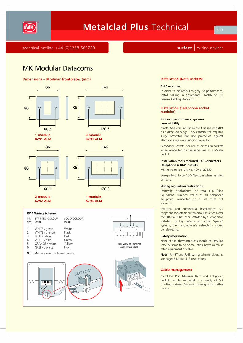
RJ1 1 W ir in g Sc h e m e
PIN ST R IPPE D C OL OU R SOL ID C OL OU R
NO. W IR E W IR E
1 W H IT E / g re e n W h ite
2 W H IT E / o ra n g e B la c k
3 B L U E / w h ite R e d
4 W H IT E / b lu e G re e n
5 OR A NG E / w h ite Y e llo w
6 G R E E N / w h ite B lu e
N o t e : M a in w ire c o lo u r is s h o w n in c a p ita ls
D im e n s io n s – M o d u la r f r o n t p la t e s (m m )
1 m o d u le
K 2 9 1 A L M
3 m o d u le
K 2 9 3 A L M
2 m o d u le
K 2 9 2 A L M
4 m o d u le
K 2 9 4 A L M
618 Metalclad P lus Technical
wiring dev ices | surface www.m kelectric.co.uk
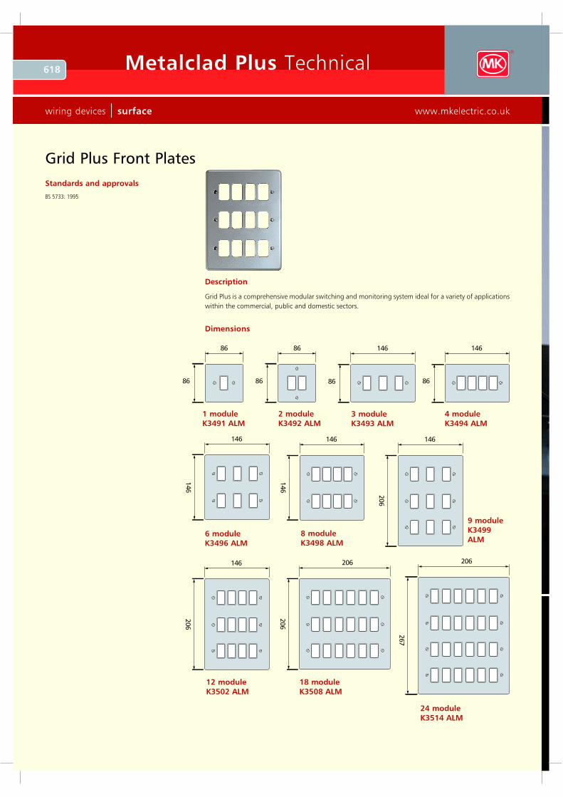
24 module
K35 14 ALM
G rid P lu s F ro n t P la te s
Dimensions
Standards and approv als
BS 5733: 1995
Description
Grid Plus is a com prehensiv e m odular switching and m onitoring sy stem ideal for a v ariety of applications
within the com m ercial, public and dom estic sectors.
8 6
8 6
8 6
8 6
1 4 6
8 6
1 4 6
8 6
1 4 6
146
1 4 6
146
1 4 6
206
1 4 6
206
2 0 6
206
2 0 6
267
1 module
K3491 ALM
2 module
K3492 ALM3 module
K3493 ALM
4 module
K3494 ALM
6 module
K3496 ALM
12 module
K35 0 2 ALM
18 module
K35 0 8 ALM
8 module
K3498 ALM
9 module
K3499
ALM