Embed Size (px)
Citation preview

M E M O R A N D U M
TO: NEC® Code-Making Panel 5
FROM: Sarah Caldwell, Project Administrator
DATE: April 20, 2018
SUBJECT: National Electrical Code® First Draft FINAL Ballot Results (A2019)
According to the final ballot results, all ballot items received the necessary affirmative
votes to pass ballot.
18 Members Eligible to Vote
1 Members Not Returned (Helfrich)
The attached report shows the number of affirmative, negative, and abstaining votes
as well as the explanation of the vote for each revision.
To pass ballot, each revision requires: (1) a simple majority of those eligible to vote and
(2) an affirmative vote of 2/3 of ballots returned. See Sections 3.3.4.3.(c) and 4.3.10.1 of
the Regulations Governing the Development of NFPA Standards.

NEC Panel 5
Eligible to Vote: 18
Not Returned : 1
William J. Helfrich
Vote Selection Votes Comments
Affirmative 15
Affirmative with Comment 0
Negative 2
David Brender No substantiation was submitted or considered that will prove that concrete that is at
or below grade level is considered to be a dry location. It has been proven that concrete
is fairly porous and will retain moisture thus it is effective as a vital component of
concrete-encased grounding electrodes. No substantiation has been submitted to
support the allegation that the interior of enclosures that are identified for a wet
location are in fact a dry location. This location should be considered to be a location
that is corrosive to aluminum connections until proven otherwise.
Election:70_NEC_P05_FD_Ballot_A2019
Results by Revision
TRUE
FR-7973, Section No. 250.64(A), See FR-7973

Nick Sasso After careful consideration, I am changing my vote to negative. David Brender is
correct. He states, "No substantiation has been submitted to support the allegation that
the interior of enclosures that are identified for a wet location are in fact a dry
location." This stands to reason. As we all know, even the interior of a PVC raceway,
being impervious to water, is still a wet location. Section 300.5(B) states, ¶-------------------
------------------------- "(B) Wet Locations. The interior of enclosures or raceways installed
underground shall be considered to be a wet location. Insulated conductors and cables
installed in these enclosures or raceways in underground installations shall comply
with310.10(C)." ¶-------------------------------------------- It is not without reason to think that
an enclosure that is approved for wet location will not perform similarly. Thus, the
theory that condensation may form is not without merit. This can be especially true in
colder climates where the electrical gear will generate a mild amount of heat. Brender
also states, "It has been proven that concrete is fairly porous and will retain moisture..."
I can take it one step further and direct the panel to Table 110.26(A)(1), Condition 2,
that states, ¶-------------------------------------------- "Concrete, brick, or tile walls shall be
considered as grounded" ¶-------------------------------------------- We should all acknowledge
the fact that moisture can be retained in the equipment - it takes decades for concrete
degradation to complete. The correct action for the panel to consider would be to get
rid of subsection (2) in it's entirety. It is clearly incorrect.
Abstain 0

1
Caldwell, Sarah
From:Sent: Wednesday, March 28, 2018 10:49 PMTo: Caldwell, SarahSubject: 7973 & 8066
Hello Sarah, I changed my vote to negative on 7973 and 8066. This is what my comment should look like (for both): After careful consideration, I am changing my vote to negative. David Brender is correct. He states, "No substantiation has been submitted to support the allegation that the interior of enclosures that are identified for a wet location are in fact a dry location." This stands to reason. As we all know, even the interior of a PVC raceway, being impervious to water, is still a wet location. Section 300.5(B) states, "(B) Wet Locations. The interior of enclosures or raceways installed underground shall be considered to be a wet location. Insulated conductors and cables installed in these enclosures or raceways in underground installations shall comply with 310.10(C)." It is not without reason to think that an enclosure that is approved for wet location will not perform similarly. Thus, the theory that condensation may form is not without merit. This can be especially true in colder climates where the electrical gear will generate a mild amount of heat. Brender also states, "It has been proven that concrete is fairly porous and will retain moisture..." I can take it one step further and direct the panel to Table 110.26(A)(1), Condition 2, that states, "Concrete, brick, or tile walls shall be considered as grounded" We should all acknowledge the fact that moisture can be retained in the equipment - it takes decades for concrete degradation to complete. The correct action for the panel to consider would be to get rid of subsection (2) in it's entirety. It is clearly incorrect. Thanks, Nick Sasso CMP-5
Eligible to Vote: 18
Not Returned : 1
William J. Helfrich
Vote Selection Votes Comments
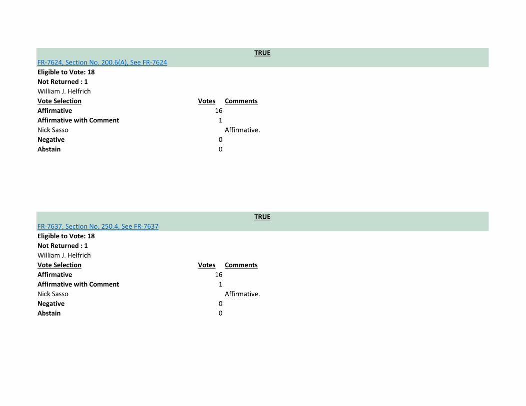
Affirmative 16
Affirmative with Comment 1
Nick Sasso Affirmative.
Negative 0
Abstain 0
Eligible to Vote: 18
Not Returned : 1
William J. Helfrich
Vote Selection Votes Comments
Affirmative 16
Affirmative with Comment 0
Negative 1
Nick Sasso Comments exceed 4000 characters - reason for negative vote is being sent to Sarah
Caldwell.
Abstain 0
TRUE
FR-7985, Section No. 250.68(C), See FR-7985
TRUE
FR-7980, Section No. 250.64(E)(1), See FR-7980
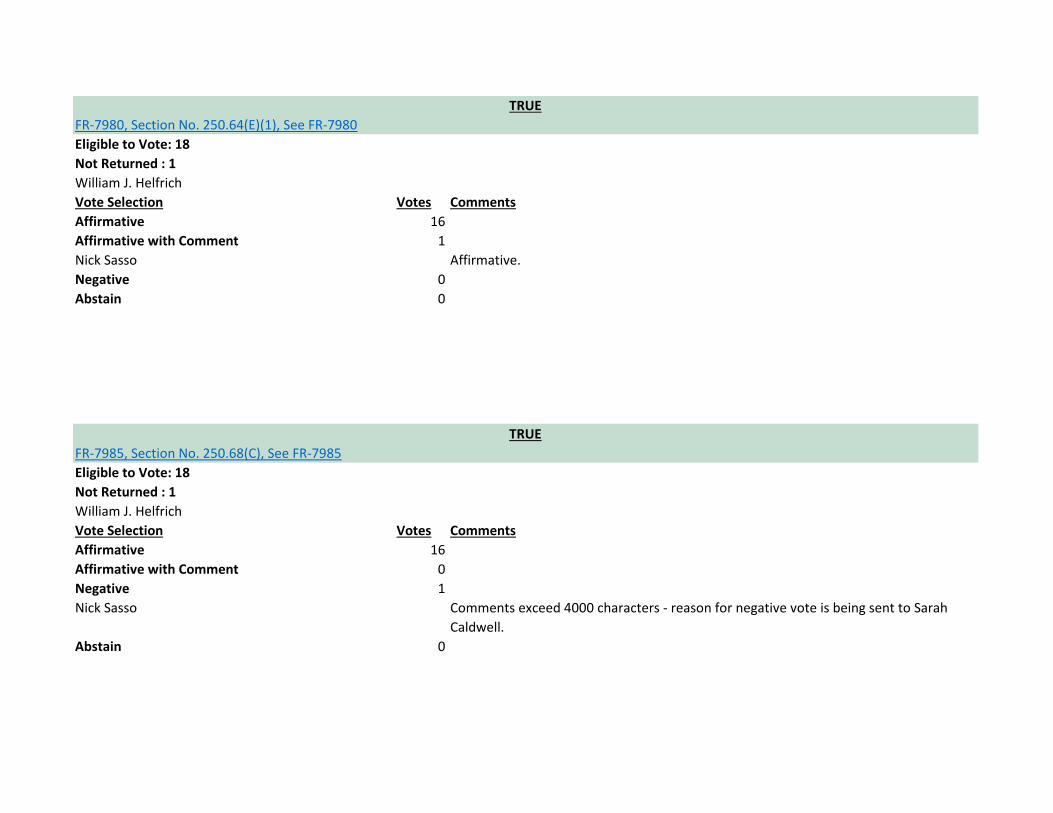
7985:
I cannot vote in favor of this change. 250.68 as written presently has too many issues and the changes being proposed do not address those serious issues. I tried to bring this up at the first draft meeting. It would be very simple to correct all the flaws, so I will repeat the reasons why 250.68 needs further review:
Is the electrical inspector actually going to be responsible for coatings that may need to be applied to steel reinforcing bar used for system grounding?
In the 2017 National Electrical Code, it states, "The rebar extension shall not be exposed to contact with the earth without corrosion protection." This sounds fine, in theory. But in practicality this statement leaves many unanswered questions. What exactly is the "corrosion protection" supposed to consist of? There are various paints and expoxies that are available for steel reinforcing bar. Is the electrical inspector actually going to be responsible to inspect paints and epoxies? Some coatings only have a few years warranty. How will an electrical inspector be able to make the determination that the correct coating was applied - and at the proper thickness, no less?
Along with the rustproofing issue comes the additional problem that the below-grade portion of the rebar will more than likely be covered with dirt when the electrical inspector comes to perform the inspection (if it is extended outside the building). Should electrical inspectors require that the electrical contractor "dig up" the rebar extension at the time of inspection if the corrosion protection isn't immediately visible? Or should inspectors simply red-tag the job for "covered before inspection" and leave? To reiterate, this requirement to use corrosion protection sounds grand in theory, but in practicality it creates a snowdrift of enforcement issues.
Should one of the most important parts of the electrical system even be allowed to utilize forms of corrosion protection?
We aren't simply talking about a piece of underground metal conduit, perhaps for a feeder. The grounding electrode system is one of the most important parts of the electrical system. Furthermore, Article 250 does not even permit mere equipment grounding conductors to be used where subject to corrosive conditions. For example, let's take Article 250.120(B)(6), which is one of the codes that is being revised in the 2020 cycle. The code states, "Bare conductors shall not come in direct contact with masonry or the earth or where subject to corrosive conditions." Another good example would be Article 250.28, which states, "Main bonding jumpers and system bonding jumpers shall be of copper or other corrosion-resistant material." Can the panel see the CONFLICT here? It sets an extremely bad precedent when we allow types of "corrosion protection" to be used for the steel grounding electrode rebar-extension. The present language is flawed.
The corrosion and enforcement problems can be totally eliminated by requiring that the rebar extension be turned up above slab with a 90° bend into a wall cavity where the wire-type grounding electrode conductor can then be connected to the extension and run to the main service disconnect. The better electrical contractors that I see do this usually turn the rebar up into an interior garage wall. Then a blank electrical plate is used after the sheetrock is installed to make the connection accessible after installation. This is actually extremely simple for the contractor to accomplish, and it solves most of the problems with the code language that we have now. The simple solution would be to eliminate the last three words in line (b) of the code change - change:
(b) "The rebar extension shall not be exposed to contact with the earth without corrosion protection."
to:
(b) "The rebar extension shall not be exposed to contact with the earth."
Making this change would eliminate the corrosion issues and the enforcement issues.
Lastly, the rebar extension is defined as a conductor - which gives rise to yet another issue. What jumps out at me here is that if the rebar extension is in fact "a conductor," used for grounding, then it should have a specified method of
CMP 5 FR 7985 Ballot Comment Sasso

connection. Take a quick gander at Article 250.8. I fully understand that steel reinforcing bar is not a "wire-type" conductor, which would have to be connected using one of the methods described in Article 250.8. But I think that 250.8 is self-evident and makes my point: since this widget is used for system grounding, exactly how the connection is to be made should be very specific. Currently, the overlap issue is completely ignored by the electrical code. It should be noted however that reinforcing bars are required to have proper overlap per the building code. For example, if there is #5 rebar in the footing that is being spliced onto another there will need to be approximately 25-inches of overlap for a tension splice. Proper lap is usually defined as being 40X the diameter of the reinforcing bar. Hence in the case of a #5 rebar, this distance works out to be 25-inches. Certain jurisdictions are allowing the rebar extension to be installed perpendicular to the footing steel. This creates a mere 0.63-inches of overlap at any point that the extension is tied to the footing steel - usually by means of a common steel wire
tie. Is 0.63-inches of steel-to-steel overlap enough? Will this minimal lap continually maintain an inherently low enough resistance-to-ground to prevent damage to the footing during lightning events, and withstand the test of time? Other jurisdictions are requiring the "full lap" as mandated by the building codes. Others still, are making up their own rules. Oregon comes to mind - the State of Oregon has incorporated into their building code that if a rebar extension is utilized for grounding electrode purposes, it must have at least 12-inches of lap. I feel that the electrical code should define the manner in which this grounding connection needs to be made; simply leaving it up to the installer creates inconsistencies from jurisdiction to jurisdiction - and we are supposed to have a National Electrical Code. Perhaps it doesn't need to be a full tension splice per the building code, but the contact length should be of some determinate value. If for nothing else, we at least need to have a determinate value for consistency's sake. I hope that the panel will be receptive to what the AHJ member has to say.

Eligible to Vote: 18
Not Returned : 1
William J. Helfrich
Vote Selection Votes Comments
Affirmative 16
Affirmative with Comment 1
Nick Sasso Affirmative.
Negative 0
Abstain 0
Eligible to Vote: 18
Not Returned : 1
William J. Helfrich
Vote Selection Votes Comments
Affirmative 15
Affirmative with Comment 2
Gary A. Beckstrand New 250.25 was created to address the needs for prescriptive requirements for
disconnects connected to the serving utility that are not defined as services. Currently
equipment connected ahead of the service disconnect in accordance with 230.82(6) is
not defined as a service. Supply-side disconnects should be grounded and bonded in a
similar fashion to a service, and the new section is needed for those installations. More
renewable and interconnected power production sources are being connected to the
serving utility directly and need prescriptive grounding and bonding requirements
properly located in Article 250.
Nick Sasso Affirmative.
Negative 0
Abstain 0
TRUE
FR-8198, Global Input, See FR-8198
TRUE
FR-7990, Section No. 250.98, See FR-7990

Eligible to Vote: 18
Not Returned : 1
William J. Helfrich
Vote Selection Votes Comments
Affirmative 15
Affirmative with Comment 2
Gary A. Beckstrand The new term is needed for connections permitted by 230.82(6) that are not
considered services. The requirements for grounding and bonding any disconnecting
means that is connected to the serving utility needs to be located in Article 250,
especially for disconnects not defined as services. Adding the new term allows for new
prescriptive requirements in new 250.25 to ensure disconnects, such as for solar, wind,
or interconnected power production installations, are grounded and bonded properly.
Nick Sasso Affirmative.
Negative 0
Abstain 0
Eligible to Vote: 18
Not Returned : 1
William J. Helfrich
Vote Selection Votes Comments
Affirmative 16
Affirmative with Comment 1
Nick Sasso Affirmative.
Negative 0
Abstain 0
TRUE
FR-7599, Definition: Ground-Fault Current Path., See FR-7599
TRUE
FR-8196, Detail, See FR-8196

Eligible to Vote: 18
Not Returned : 1
William J. Helfrich
Vote Selection Votes Comments
Affirmative 16
Affirmative with Comment 1
Nick Sasso Affirmative.
Negative 0
Abstain 0
Eligible to Vote: 18
Not Returned : 1
William J. Helfrich
Vote Selection Votes Comments
Affirmative 14
Affirmative with Comment 2
Gary A. Beckstrand The proposed change should be accepted. By adding the new language, the
identification of grounded conductors for multiconductor cables is aligned with the
general rule in 200.6 (A) and (B). Grounded conductors whenever possible should be
identified by a continuous white or grey color for safety.
Nick Sasso Affirmative.
Negative 1
TRUE
FR-7625, Section No. 200.6(E), See FR-7625
TRUE
FR-7602, Definition: Grounding Conductor, Equipment (EGC)., See FR-7602
David Brender While CDA supports the revisions to 200.6(E), CMP-5's failure to accept PI-2775 is not
acceptable. The substantiation that was provided is more than adequate to support the
deletion of the requirement for qualified persons to identify the grounded conductor of
multiconductor cables. PI-2775 should have been accepted.
Abstain 0
Eligible to Vote: 18
Not Returned : 1
William J. Helfrich
Vote Selection Votes Comments
Affirmative 16
Affirmative with Comment 1
Nick Sasso Affirmative.
Negative 0
Abstain 0
Eligible to Vote: 18
Not Returned : 1
William J. Helfrich
Vote Selection Votes Comments
Affirmative 16
Affirmative with Comment 1
Nick Sasso Affirmative.
Negative 0
Abstain 0
TRUE
FR-7631, Section No. 200.10(B), See FR-7631
TRUE
FR-7629, Section No. 200.9, See FR-7629

Eligible to Vote: 18
Not Returned : 1
William J. Helfrich
Vote Selection Votes Comments
Affirmative 16
Affirmative with Comment 1
Nick Sasso Affirmative.
Negative 0
Abstain 0
Eligible to Vote: 18
Not Returned : 1
William J. Helfrich
Vote Selection Votes Comments
Affirmative 15
Affirmative with Comment 2
Gary A. Beckstrand The new Informational Note directs code users to NFPA 70E-2018, Standard for
Electrical Safety in the Workplace Annex O which addresses ways to limit incident
energy levels of arcing currents through an overcurrent device during a faulted
condition which are dependent on available fault current at the source of the fault.
Users of the Code will find this information important for safety.
Nick Sasso Affirmative.
Negative 0
Abstain 0
TRUE
FR-7643, Section No. 250.20(B), See FR-7643
TRUE
FR-7639, Section No. 250.12, See FR-7639

Eligible to Vote: 18
Not Returned : 1
William J. Helfrich
Vote Selection Votes Comments
Affirmative 16
Affirmative with Comment 1
Nick Sasso Affirmative.
Negative 0
Abstain 0
Eligible to Vote: 18
Not Returned : 1
William J. Helfrich
Vote Selection Votes Comments
Affirmative 16
Affirmative with Comment 1
Nick Sasso Affirmative.
Negative 0
Abstain 0
TRUE
FR-7685, Section No. 250.28(A), See FR-7685
TRUE
FR-7680, Section No. 250.26, See FR-7680

Eligible to Vote: 18
Not Returned : 1
William J. Helfrich
Vote Selection Votes Comments
Affirmative 16
Affirmative with Comment 1
Nick Sasso Affirmative.
Negative 0
Abstain 0
Eligible to Vote: 18
Not Returned : 1
William J. Helfrich
Vote Selection Votes Comments
Affirmative 16
Affirmative with Comment 1
Nick Sasso Affirmative.
Negative 0
Abstain 0
TRUE
FR-7818, Section No. 250.34, See FR-7818
TRUE
FR-7759, Section No. 250.32(A), See FR-7759

Eligible to Vote: 18
Not Returned : 1
William J. Helfrich
Vote Selection Votes Comments
Affirmative 16
Affirmative with Comment 1
Nick Sasso Affirmative.
Negative 0
Abstain 0
Eligible to Vote: 18
Not Returned : 1
William J. Helfrich
Vote Selection Votes Comments
Affirmative 16
Affirmative with Comment 1
Nick Sasso Affirmative.
Negative 0
Abstain 0
TRUE
FR-7902, Section No. 250.64(E)(3), See FR-7902
TRUE
FR-7781, Section No. 250.36 [Excluding any Sub-Sections], See FR-7781

Eligible to Vote: 18
Not Returned : 1
William J. Helfrich
Vote Selection Votes Comments
Affirmative 16
Affirmative with Comment 1
Nick Sasso Affirmative.
Negative 0
Abstain 0
Eligible to Vote: 18
Not Returned : 1
William J. Helfrich
Vote Selection Votes Comments
Affirmative 16
Affirmative with Comment 1
Nick Sasso Affirmative.
Negative 0
Abstain 0
TRUE
FR-7542, Section No. 250.136, See FR-7542
TRUE
FR-7920, Section No. 250.92(B), See FR-7920

Eligible to Vote: 18
Not Returned : 1
William J. Helfrich
Vote Selection Votes Comments
Affirmative 16
Affirmative with Comment 1
Nick Sasso Affirmative.
Negative 0
Abstain 0
Eligible to Vote: 18
Not Returned : 1
William J. Helfrich
Vote Selection Votes Comments
Affirmative 16
Affirmative with Comment 1
Nick Sasso Affirmative.
Negative 0
Abstain 0
TRUE
FR-7548, Section No. 250.142(B), See FR-7548
TRUE
FR-7545, Section No. 250.142(A), See FR-7545

Eligible to Vote: 18
Not Returned : 1
William J. Helfrich
Vote Selection Votes Comments
Affirmative 16
Affirmative with Comment 1
Nick Sasso Affirmative.
Negative 0
Abstain 0
Eligible to Vote: 18
Not Returned : 1
William J. Helfrich
Vote Selection Votes Comments
Affirmative 16
Affirmative with Comment 1
Nick Sasso Affirmative.
Negative 0
Abstain 0
TRUE
FR-7568, Section No. 250.176, See FR-7568
TRUE
FR-7566, Section No. 250.174(C), See FR-7566

Eligible to Vote: 18
Not Returned : 1
William J. Helfrich
Vote Selection Votes Comments
Affirmative 16
Affirmative with Comment 1
Nick Sasso Affirmative.
Negative 0
Abstain 0
Eligible to Vote: 18
Not Returned : 1
William J. Helfrich
Vote Selection Votes Comments
Affirmative 16
Affirmative with Comment 1
Nick Sasso Affirmative.
Negative 0
Abstain 0
TRUE
FR-7819, Section No. 250.184(C), See FR-7819
TRUE
FR-7814, Section No. 250.184(A)(1), See FR-7814

Eligible to Vote: 18
Not Returned : 1
William J. Helfrich
Vote Selection Votes Comments
Affirmative 16
Affirmative with Comment 1
Nick Sasso Affirmative.
Negative 0
Abstain 0
Eligible to Vote: 18
Not Returned : 1
William J. Helfrich
Vote Selection Votes Comments
Affirmative 16
Affirmative with Comment 1
Nick Sasso Affirmative.
Negative 0
Abstain 0
TRUE
FR-7527, Part VII., See FR-7527
TRUE
FR-7651, Part II., See FR-7651

Eligible to Vote: 18
Not Returned : 1
William J. Helfrich
Vote Selection Votes Comments
Affirmative 15
Affirmative with Comment 2
Gary A. Beckstrand The Main Bonding Jumper frequently connects supply-side bonding jumpers to the
grounded conductor in addition to the equipment grounding conductor. The
modification to the definition should allow the definition of system bonding jumper
(see new definition for supply-side bonding jumper) to eventually be integrated into
this term for simplification of bonding terms.
Nick Sasso Affirmative.
Negative 0
Abstain 0
Eligible to Vote: 18
Not Returned : 1
William J. Helfrich
Vote Selection Votes Comments
Affirmative 16
Affirmative with Comment 1
Nick Sasso Affirmative.
Negative 0
Abstain 0
TRUE
FR-7614, Section No. 200.3, See FR-7614
TRUE
FR-8070, Definition: Bonding Jumper, Main., See FR-8070
Eligible to Vote: 18
Not Returned : 1
William J. Helfrich
Vote Selection Votes Comments
Affirmative 16
Affirmative with Comment 1
Nick Sasso Affirmative.
Negative 0
Abstain 0
Eligible to Vote: 18
Not Returned : 1
William J. Helfrich
Vote Selection Votes Comments
Affirmative 16
Affirmative with Comment 1
Nick Sasso Affirmative.
Negative 0
Abstain 0
TRUE
FR-7637, Section No. 250.4, See FR-7637
TRUE
FR-7624, Section No. 200.6(A), See FR-7624

Eligible to Vote: 18
Not Returned : 1
William J. Helfrich
Vote Selection Votes Comments
Affirmative 16
Affirmative with Comment 1
Nick Sasso Affirmative.
Negative 0
Abstain 0
Eligible to Vote: 18
Not Returned : 1
William J. Helfrich
Vote Selection Votes Comments
Affirmative 16
Affirmative with Comment 1
Nick Sasso Affirmative.
Negative 0
Abstain 0
TRUE
FR-8061, Section No. 250.24, See FR-8061
TRUE
FR-8107, Section No. 250.6(D), See FR-8107
Eligible to Vote: 18
Not Returned : 1
William J. Helfrich
Vote Selection Votes Comments
Affirmative 16
Affirmative with Comment 1
Nick Sasso Affirmative.
Negative 0
Abstain 0
Eligible to Vote: 18
Not Returned : 1
William J. Helfrich
Vote Selection Votes Comments
Affirmative 16
Affirmative with Comment 1
Nick Sasso Affirmative.
Negative 0
Abstain 0
TRUE
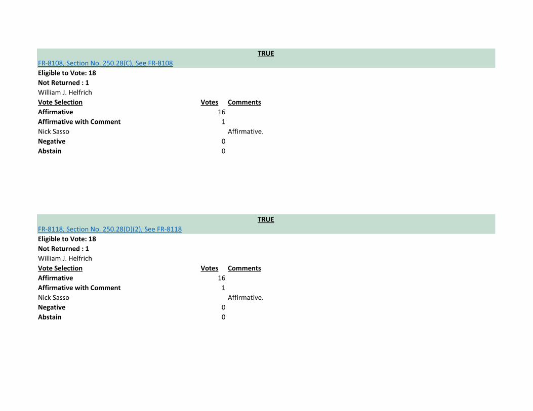
FR-8118, Section No. 250.28(D)(2), See FR-8118
TRUE
FR-8108, Section No. 250.28(C), See FR-8108

Eligible to Vote: 18
Not Returned : 1
William J. Helfrich
Vote Selection Votes Comments
Affirmative 16
Affirmative with Comment 1
Nick Sasso Affirmative.
Negative 0
Abstain 0
Eligible to Vote: 18
Not Returned : 1
William J. Helfrich
Vote Selection Votes Comments
Affirmative 16
Affirmative with Comment 1
Nick Sasso Affirmative.
Negative 0
Abstain 0
TRUE
FR-8109, Section No. 250.32(D), See FR-8109
TRUE
FR-8097, Section No. 250.30, See FR-8097

Eligible to Vote: 18
Not Returned : 1
William J. Helfrich
Vote Selection Votes Comments
Affirmative 16
Affirmative with Comment 1
Nick Sasso Affirmative.
Negative 0
Abstain 0
Eligible to Vote: 18
Not Returned : 1
William J. Helfrich
Vote Selection Votes Comments
Affirmative 16
Affirmative with Comment 1
Nick Sasso Affirmative.
Negative 0
Abstain 0
TRUE
FR-7898, Sections 250.64(B)(2), 250.64(B)(3), See FR-7898
TRUE
FR-8060, Section No. 250.53, See FR-8060
Eligible to Vote: 18
Not Returned : 1
William J. Helfrich
Vote Selection Votes Comments
Affirmative 16
Affirmative with Comment 1
Nick Sasso Affirmative.
Negative 0
Abstain 0
Eligible to Vote: 18
Not Returned : 1
William J. Helfrich
Vote Selection Votes Comments
Affirmative 16
Affirmative with Comment 1
Nick Sasso Affirmative.
Negative 0
Abstain 0
TRUE
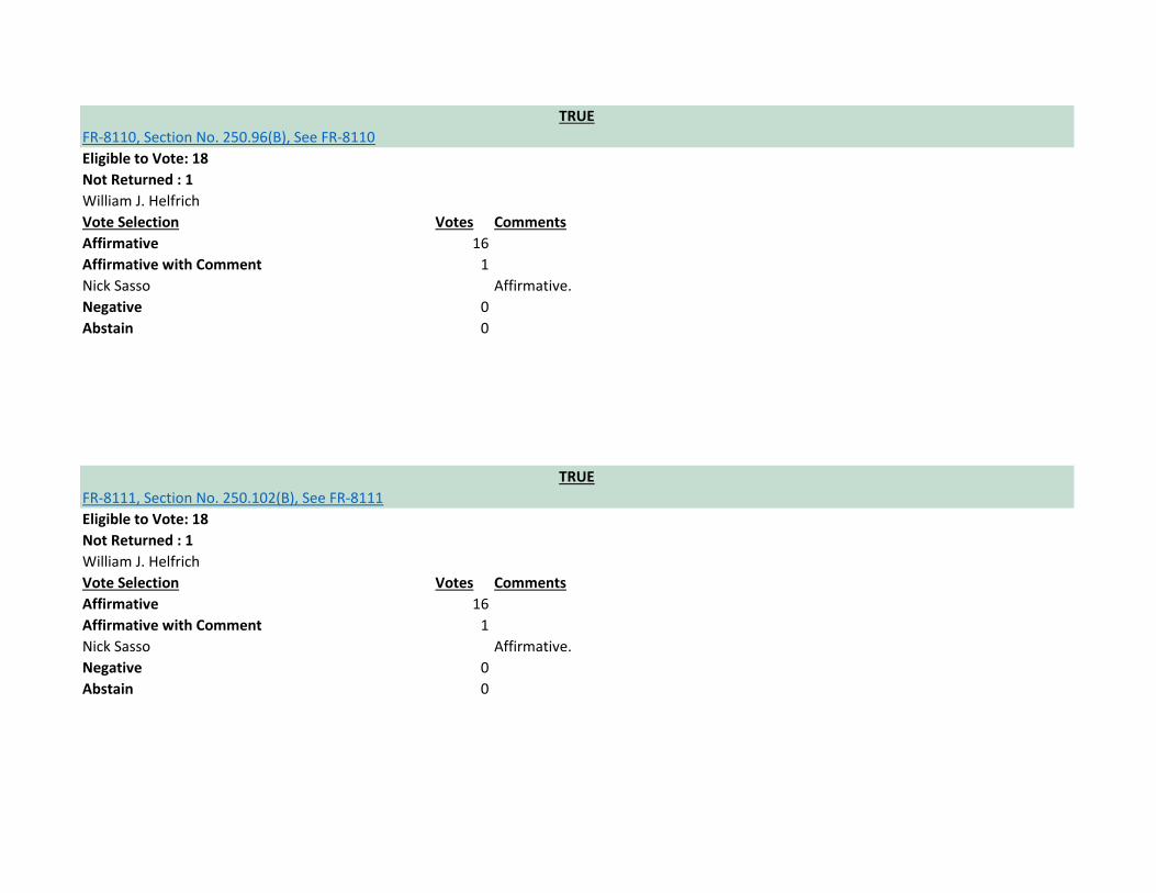
FR-8111, Section No. 250.102(B), See FR-8111
TRUE
FR-8110, Section No. 250.96(B), See FR-8110

Eligible to Vote: 18
Not Returned : 1
William J. Helfrich
Vote Selection Votes Comments
Affirmative 14
Affirmative with Comment 3
David Brender It should be noted that although the Panel voted overwhelmingly for this FR, there
were no studies or calculations submitted that justify revision of the largest grounding
conductor from 4/0 to 3/0.
G. Scott Harding This correction is important as the inadvertent increase was significant and
unnecessary. For example, for a building with a 4000 amp service, the 2014 code (and
all previous applicable editions back to 1978) required a maximum Grounding Electrode
Conductor size to be 3/0 Copper. The 2017 code changed that to be 750Kcmil Copper.
There has been no evidence of any problems in the field by using the sizing
requirements established in the 1978 NEC.
Nick Sasso Affirmative.
Negative 0
Abstain 0
TRUE
FR-8031, Section No. 250.104(A)(1), See FR-8031

Eligible to Vote: 18
Not Returned : 1
William J. Helfrich
Vote Selection Votes Comments
Affirmative 16
Affirmative with Comment 1
Nick Sasso Affirmative.
Negative 0
Abstain 0
Eligible to Vote: 18
Not Returned : 1
William J. Helfrich
Vote Selection Votes Comments
Affirmative 15
Affirmative with Comment 2
G. Scott Harding This correction is important as the inadvertent increase was significant and
unnecessary. For example, for a building with a 4000 amp service, the 2014 code (and
all previous applicable editions back to 1978) required a maximum Grounding Electrode
Conductor size to be 3/0 Copper. The 2017 code changed that to be 750Kcmil Copper.
There has been no evidence of any problems in the field by using the sizing
requirements established in the 1978 NEC.
Nick Sasso Affirmative.
Negative 0
Abstain 0
TRUE
FR-8034, Section No. 250.104(C), See FR-8034
TRUE
FR-8033, Section No. 250.104(A)(3), See FR-8033

Eligible to Vote: 18
Not Returned : 1
William J. Helfrich
Vote Selection Votes Comments
Affirmative 15
Affirmative with Comment 2
G. Scott Harding This correction is important as the inadvertent increase was significant and
unnecessary. For example, for a building with a 4000 amp service, the 2014 code (and
all previous applicable editions back to 1978) required a maximum Grounding Electrode
Conductor size to be 3/0 Copper. The 2017 code changed that to be 750Kcmil Copper.
There has been no evidence of any problems in the field by using the sizing
requirements established in the 1978 NEC.
Nick Sasso Affirmative.
Negative 0
Abstain 0
Eligible to Vote: 18
Not Returned : 1
William J. Helfrich
Vote Selection Votes Comments
Affirmative 16
Affirmative with Comment 1
Nick Sasso Affirmative.
Negative 0
Abstain 0
TRUE
FR-8038, Section No. 250.106, See FR-8038
TRUE
FR-8035, Sections 250.104(D)(1), 250.104(D)(2), See FR-8035

Eligible to Vote: 18
Not Returned : 1
William J. Helfrich
Vote Selection Votes Comments
Affirmative 16
Affirmative with Comment 1
Nick Sasso Affirmative.
Negative 0
Abstain 0
Eligible to Vote: 18
Not Returned : 1
William J. Helfrich
Vote Selection Votes Comments
Affirmative 16
Affirmative with Comment 1
Nick Sasso Affirmative.
Negative 0
Abstain 0
TRUE
FR-8040, Section No. 250.114, See FR-8040
TRUE
FR-8039, Section No. 250.112(K), See FR-8039

Eligible to Vote: 18
Not Returned : 1
William J. Helfrich
Vote Selection Votes Comments
Affirmative 16
Affirmative with Comment 1
Nick Sasso Affirmative.
Negative 0
Abstain 0
Eligible to Vote: 18
Not Returned : 1
William J. Helfrich
Vote Selection Votes Comments
Affirmative 15
Affirmative with Comment 0
Negative 2
TRUE
FR-8043, Section No. 250.119(B), See FR-8043
TRUE
FR-8041, Section No. 250.118, See FR-8041

Gary A. Beckstrand Removal of the requirements of conditions maintenance and supervision to ensure
qualified persons service the installation negates the requirements of the general rule
for continuous identification of the equipment grounding conductor. Removal of the
language is a serious reduction in safety for identification requirements for the EGC.
Requiring the equipment grounding conductor pulled into a raceway to be continuously
identified green and an equipment grounding conductor installed in a cable not to be
continuously identified is in complete contradiction which the result of this
modification and should be rejected. The equipment grounding conductor serves an
essential and vital safety function for grounding and bonding equipment and it is
imperative that it be clearly identified for installers. Multiconductor cables are available
with correctly identified equipment grounding conductors. The proper cable should be
used for the installation rather than re-identifying an equipment grounding conductor
in the field to make the wrong cable suitable for the installation. Too frequently failure
to re-identify a conductor in a cable is a common violation and could lead to
inadvertent energization of equipment enclosures. The NEC should be consistent, and
removal of the language will make it inconsistent with the requirements of 200.6(E).
The Panel had voted in favor of keeping the identical requirement in place for 200.6(E)
based upon a similar public input and the requirement should remain in place and this
revision rejected.

Nick Sasso After pondering this change some, I'm voting against it. ¶------------------------------------------
-- Would the average homeowner running a piece of NM cable actually take the time to
re-identify a conductor? ¶-------------------------------------------- For example, if a
homeowner makes a grounded conductor green by the use of green tape (from white
to green) at one end of the run, would they actually go back to the panel and properly
re-identify the conductor at that end? ¶-------------------------------------------- In many cases,
probably not. This could lead to problems, especially if the homeowner is working out
of a sub-panel. If the house is ever sold, the new owner could inherit a potential
problem. ¶-------------------------------------------- I believe that the code is written the way it
is for a reason, and a lot of it has to do with NM cable and residential work being done
by people that are not qualified. I think that this section should stay as it is.
Abstain 0
Eligible to Vote: 18
Not Returned : 1
William J. Helfrich
Vote Selection Votes Comments
Affirmative 15
Affirmative with Comment 0
Negative 2
TRUE
FR-8066, Section No. 250.120(B), See FR-8066
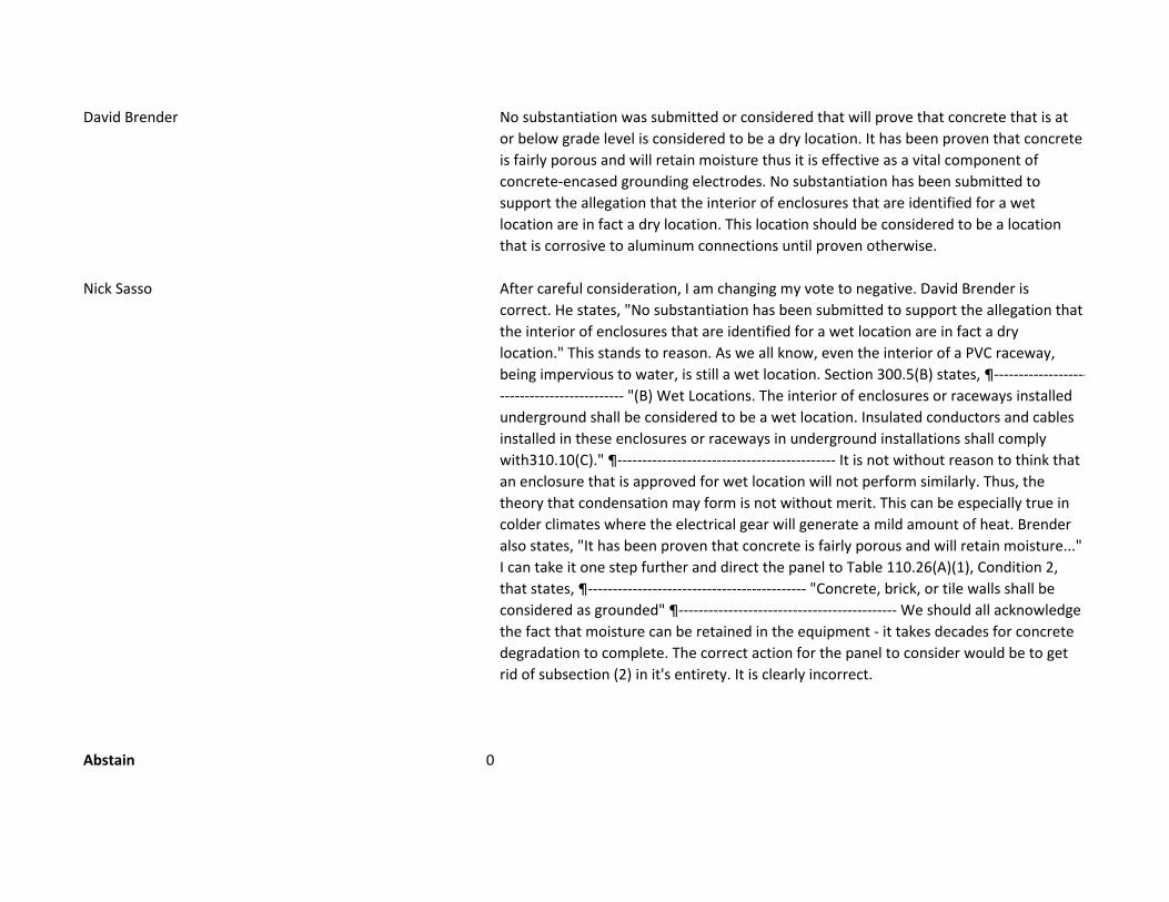
David Brender No substantiation was submitted or considered that will prove that concrete that is at
or below grade level is considered to be a dry location. It has been proven that concrete
is fairly porous and will retain moisture thus it is effective as a vital component of
concrete-encased grounding electrodes. No substantiation has been submitted to
support the allegation that the interior of enclosures that are identified for a wet
location are in fact a dry location. This location should be considered to be a location
that is corrosive to aluminum connections until proven otherwise.
Nick Sasso After careful consideration, I am changing my vote to negative. David Brender is
correct. He states, "No substantiation has been submitted to support the allegation that
the interior of enclosures that are identified for a wet location are in fact a dry
location." This stands to reason. As we all know, even the interior of a PVC raceway,
being impervious to water, is still a wet location. Section 300.5(B) states, ¶-------------------
------------------------- "(B) Wet Locations. The interior of enclosures or raceways installed
underground shall be considered to be a wet location. Insulated conductors and cables
installed in these enclosures or raceways in underground installations shall comply
with310.10(C)." ¶-------------------------------------------- It is not without reason to think that
an enclosure that is approved for wet location will not perform similarly. Thus, the
theory that condensation may form is not without merit. This can be especially true in
colder climates where the electrical gear will generate a mild amount of heat. Brender
also states, "It has been proven that concrete is fairly porous and will retain moisture..."
I can take it one step further and direct the panel to Table 110.26(A)(1), Condition 2,
that states, ¶-------------------------------------------- "Concrete, brick, or tile walls shall be
considered as grounded" ¶-------------------------------------------- We should all acknowledge
the fact that moisture can be retained in the equipment - it takes decades for concrete
degradation to complete. The correct action for the panel to consider would be to get
rid of subsection (2) in it's entirety. It is clearly incorrect.
Abstain 0

1
Caldwell, Sarah
From:Sent: Wednesday, March 28, 2018 10:49 PMTo: Caldwell, SarahSubject: 7973 & 8066
Hello Sarah, I changed my vote to negative on 7973 and 8066. This is what my comment should look like (for both): After careful consideration, I am changing my vote to negative. David Brender is correct. He states, "No substantiation has been submitted to support the allegation that the interior of enclosures that are identified for a wet location are in fact a dry location." This stands to reason. As we all know, even the interior of a PVC raceway, being impervious to water, is still a wet location. Section 300.5(B) states, "(B) Wet Locations. The interior of enclosures or raceways installed underground shall be considered to be a wet location. Insulated conductors and cables installed in these enclosures or raceways in underground installations shall comply with 310.10(C)." It is not without reason to think that an enclosure that is approved for wet location will not perform similarly. Thus, the theory that condensation may form is not without merit. This can be especially true in colder climates where the electrical gear will generate a mild amount of heat. Brender also states, "It has been proven that concrete is fairly porous and will retain moisture..." I can take it one step further and direct the panel to Table 110.26(A)(1), Condition 2, that states, "Concrete, brick, or tile walls shall be considered as grounded" We should all acknowledge the fact that moisture can be retained in the equipment - it takes decades for concrete degradation to complete. The correct action for the panel to consider would be to get rid of subsection (2) in it's entirety. It is clearly incorrect. Thanks, Nick Sasso CMP-5

Eligible to Vote: 18
Not Returned : 1
William J. Helfrich
Vote Selection Votes Comments
Affirmative 16
Affirmative with Comment 1
Nick Sasso I'm voting yes on the change. ¶-------------------------------------------- However for the
record, the exception needs to be stricken from this code. It is practically impossible
that the exception could ever be complied with. It also creates great difficulty from an
enforcement perspective. The exception does not help the inspector. ¶-----------------------
--------------------- It's like saying - you can have a chandelier in your shower "as long as it
complies with the rest of the electrical code."
Negative 0
Abstain 0
TRUE
FR-7544, Section No. 250.121, See FR-7544
Eligible to Vote: 18
Not Returned : 1
William J. Helfrich
Vote Selection Votes Comments
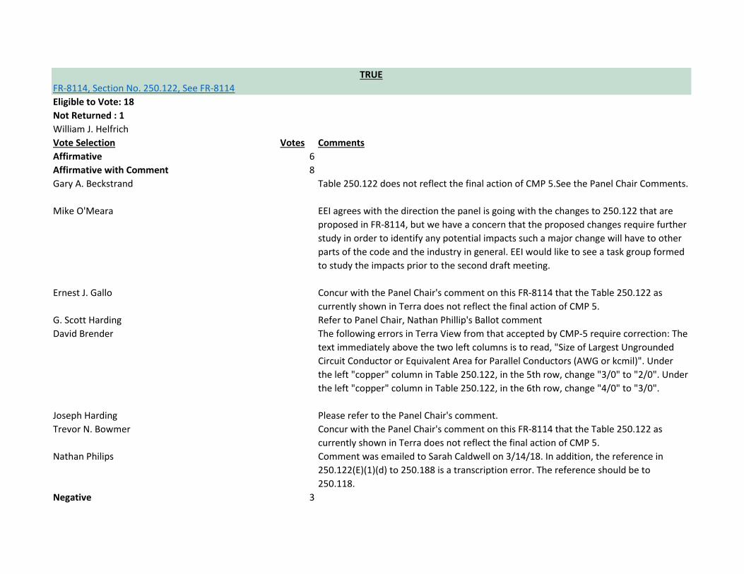
Affirmative 6
Affirmative with Comment 8
Gary A. Beckstrand Table 250.122 does not reflect the final action of CMP 5.See the Panel Chair Comments.
Mike O'Meara EEI agrees with the direction the panel is going with the changes to 250.122 that are
proposed in FR-8114, but we have a concern that the proposed changes require further
study in order to identify any potential impacts such a major change will have to other
parts of the code and the industry in general. EEI would like to see a task group formed
to study the impacts prior to the second draft meeting.
Ernest J. Gallo Concur with the Panel Chair's comment on this FR-8114 that the Table 250.122 as
currently shown in Terra does not reflect the final action of CMP 5.
G. Scott Harding Refer to Panel Chair, Nathan Phillip's Ballot comment
David Brender The following errors in Terra View from that accepted by CMP-5 require correction: The
text immediately above the two left columns is to read, "Size of Largest Ungrounded
Circuit Conductor or Equivalent Area for Parallel Conductors (AWG or kcmil)". Under
the left "copper" column in Table 250.122, in the 5th row, change "3/0" to "2/0". Under
the left "copper" column in Table 250.122, in the 6th row, change "4/0" to "3/0".
Joseph Harding Please refer to the Panel Chair's comment.
Trevor N. Bowmer Concur with the Panel Chair's comment on this FR-8114 that the Table 250.122 as
currently shown in Terra does not reflect the final action of CMP 5.
Nathan Philips Comment was emailed to Sarah Caldwell on 3/14/18. In addition, the reference in
250.122(E)(1)(d) to 250.188 is a transcription error. The reference should be to
250.118.
Negative 3
TRUE
FR-8114, Section No. 250.122, See FR-8114

Gregory J. Steinman NEMA supports the concept but needs to see more substantiation to verify that the
new requirements provide a safe installation.
Joseph F. Andre The FR should be rejected on lack of need, lack of technical substantiation, and the
resultant decrease in safety. There is no reason given or implied that making such a
drastic change is needed. No information is provided to indicate the existing Table
250.122, based on the size of the overcurrent device, is wrong, inadequate, or
confusing, or that this change will be an improvement. In fact, the existing Table is
simple and straightforward and has been proven safe for decades. The Panel statement
only says that the Table is being changed but does give any technical reason for doing
so. The use of a UL Standard for MC cable and TC cable is not representative of all
installations or conditions: it addresses a specific, tightly controlled factory
manufactured wiring method, in which the equipment grounding conductor is installed
within a jacket in a determined location/configuration. This concept cannot possibly be
valid for all configurations where the proximity of the EGC to the phase conductors is
random, as in a trench, wireway, or raceway. The physics of these installations should
not be assumed to be the same as for construction of specific cables. It needs to be
noted that these standards were not made available to the Panel at time of the Public
Input, nor during the deliberations during the PI hearings; only a few minutes was
offered to a few CMP-5 members. This in itself should disqualify the change due to lack
of ability to review the standards for relevancy. The comment that this action is
consistent with sizing of supply-side bonding conductors and grounded conductors in
Table 250.102(C)(1) is not accurate, as those conductors generally do not have an
known overcurrent protection. Only the protective device applied by the utility is
applicable, and is not controlled by the NEC and often will not come close to protecting
a conductor sized per the NEC. The hope is that the supply-side bonding jumper will
survive long enough to open some device on the utility side of the premises wiring, or
possibly until the shorted conductor burns through.

Decades of experience indicates that this is not a precise application. Obviously, the
function of these conductors is vastly different from the equipment grounding
conductors regulated by 250.122 and cannot be realistically compared. The change to
250.122(F) for parallel circuits is equally troubling. There is no technical substantiation
for such a radical change. This proposed modification will drastically reduce the size of
the EGC and put electrical installations at unnecessary risk. It was stated that there is
only a single, rare condition in which a single EGC might be required to carry the entire
fault current in a parallel installation, and the philosophy is that risk is acceptable.
However, there are multiple publications that identify a much more likely situation: in
which an insulation failure in a run of cable or non-metallic raceway faults to a bare
equipment grounding conductor. This situation is not so uncommon and I have
personally been involved in two repairs of just such a fault. As is stated in Soares, this
fault is fed from both ends by all of the parallel ungrounded phase conductors, and the
single EGC must carry that entire fault for the distance between the fault and the
termination. Again as pointed out in Soares, most of these faults are of the arcing type,
adding to the impedance imposed by the single EGC, making it less likely that a large
frame breaker could clear the fault before significant damage to the components, or
even before the EGC completely melts through. The rare conflict that is noted between
provisions of 250.122(B) and Table 250.122 in the current NEC can be resolved in a
much less radical method, by requiring the increase only when the upsizing of the phase
conductor would require a larger equipment grounding conductor. We must also
remember that the membership of NFPA rejected the proposed change to (F) in 2016.

Nick Sasso There is no technical substantiation for this change. The simple fact that there are a
couple of UL tables based on wire size instead of breaker size does not warrant a
change of this magnitude. ¶-------------------------------------------- The net effect of the
proposed change is that it would no longer require equipment grounding conductors to
be sized at "full size" for parallel feeder installations. The size of the equipment
grounding conductor in each parallel leg is sized to carry the maximum amount of fault
current that can be imposed at any one time. Hence, each equipment grounding
conductor is fully dependent upon the size of the overcurrent device. I cannot vote for
this code change since it would allow the equipment grounding conductors to be sized
SMALLER with regard to parallel installations. We would in effect, "lessen" the current
code. ¶-------------------------------------------- I have researched as far back as the 1968 NEC.
Table 250.122 has always been there. The year is now 2018. If we do the math, this
makes half a century that 250.122 has been successfully used in the form that it exists
now. There is no ambiguous language that has existed for the last 50 years. General
contractors, electricians, journeyman electricians, electrical helpers, architects,
engineers, and others have come to know and rely on Table 250.122. To attempt to
change the table now will only detract from the National Electrical Code, not add value
to it. Users of the code consider this section as "etched in stone." Working-class people
have come to rely and depend on that article as it is now. Article 250.122 is a
"keystone" to the National Electrical Code. Let us not change one of the NEC's most
proven articles. ¶-------------------------------------------- Another point that needs to be
made - is that we no longer live in a relatively safe world. We must not just be able to
"think outside of the box;" we must be willing to go even further - way beyond the box -
with regard to electrical construction. I try never to think of "what could go wrong." I
never predict how an accident or disaster may or may not unfold. While it may be
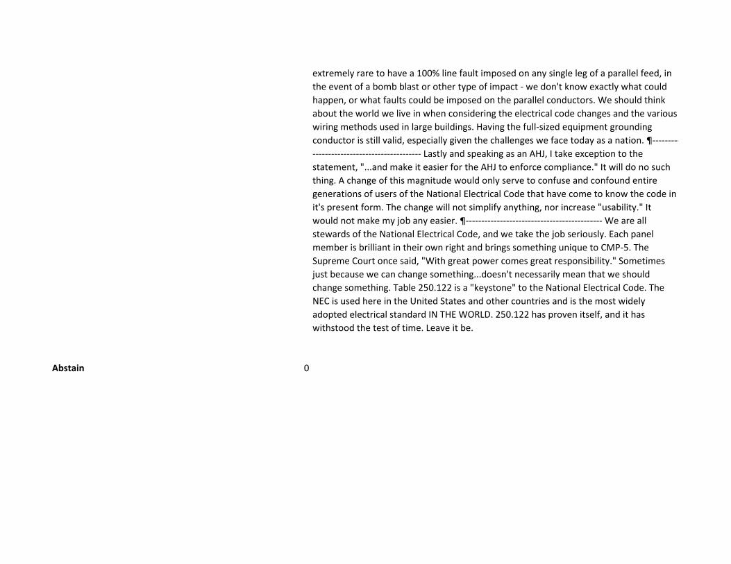
extremely rare to have a 100% line fault imposed on any single leg of a parallel feed, in
the event of a bomb blast or other type of impact - we don't know exactly what could
happen, or what faults could be imposed on the parallel conductors. We should think
about the world we live in when considering the electrical code changes and the various
wiring methods used in large buildings. Having the full-sized equipment grounding
conductor is still valid, especially given the challenges we face today as a nation. ¶---------
----------------------------------- Lastly and speaking as an AHJ, I take exception to the
statement, "...and make it easier for the AHJ to enforce compliance." It will do no such
thing. A change of this magnitude would only serve to confuse and confound entire
generations of users of the National Electrical Code that have come to know the code in
it's present form. The change will not simplify anything, nor increase "usability." It
would not make my job any easier. ¶-------------------------------------------- We are all
stewards of the National Electrical Code, and we take the job seriously. Each panel
member is brilliant in their own right and brings something unique to CMP-5. The
Supreme Court once said, "With great power comes great responsibility." Sometimes
just because we can change something...doesn't necessarily mean that we should
change something. Table 250.122 is a "keystone" to the National Electrical Code. The
NEC is used here in the United States and other countries and is the most widely
adopted electrical standard IN THE WORLD. 250.122 has proven itself, and it has
withstood the test of time. Leave it be.
Abstain 0

CMP 5 Chair's Ballot Comment on FR 8114:
Table 250.122 does not reflect the final action of CMP 5. The range of conductor sizes in the table should be modified as follows:
Cu AL
2 - 23/0 1/0 - 4/0
34/0 - 300 250 - 450
CMP 5 prepared the following table identifying other sections of the 2017 NEC that are affected by PI 8114. This table was provided to the Correlating Committee for its use and is provided here as public information:
Sections of 2017 NEC Affected by Changes to 250.122
SECTION AFFECTED TEXT PROPOSED REVISED TEXT 215.2(A)(2)(b)(2) (2) Grounded Conductor. The size of the
feeder circuit grounded conductor shall notbe smaller than that required by 250.122,except that 250.122(F) shall not applywhere grounded conductors are run inparallel.
(2) Grounded Conductor. The sizeof the feeder circuit groundedconductor shall not be smallerthan that required by 250.122.
215.2(B) (B) Feeders over 600 Volts. The ampacity ofconductors shall be in accordance with310.15 and 310.60 as applicable. Whereinstalled, the size of the feeder-circuitgrounded conductor shall not be smallerthan that required by 250.122, except that250.122(F) shall not apply where groundedconductors are run in parallel. Feederconductors over 600 volts shall be sized inaccordance with 215.2(B)(1), (B)(2), or(B)(3).
(B) Feeders over 600 Volts. Theampacity of conductors shall be inaccordance with 310.15 and310.60 as applicable. Whereinstalled, the size of the feeder-circuit grounded conductor shallnot be smaller than that requiredby 250.122, except that250.122(E) shall not apply wheregrounded conductors are run inparallel. Feeder conductors over600 volts shall be sized inaccordance with 215.2(B)(1),(B)(2), or (B)(3).
250.102(D) (Not addressed at FD meeting)
(D) Size — Equipment Bonding Jumper onLoad Side of an Overcurrent Device. Theequipment bonding jumper on the load sideof an overcurrent device(s) shall be sized inaccordance with 250.122.A single common continuous equipmentbonding jumper shall be permitted toconnect two or more raceways or cables ifthe bonding jumper is sized in accordancewith 250.122 for the largest overcurrentdevice supplying circuits therein.
(D) Size — Equipment BondingJumper on Load Side of anOvercurrent Device. Theequipment bonding jumper onthe load side of an overcurrentdevice(s) shall be sized inaccordance with 250.122.A single common continuousequipment bonding jumper shallbe permitted to connect two ormore raceways or cables if the
CMP 5 FR 8114 Ballot Comment Philips

bonding jumper is sized in accordance with 250.122.
250.104(B) (Not addressed at FD meeting)
(B) Other Metal Piping. If installed in or attached to a building or structure, a metal piping system(s), including gas piping, that is likely to become energized shall be bonded to any of the following: (1) Equipment grounding conductor for the circuit that is likely to energize the piping system (2) Service equipment enclosure (3) Grounded conductor at the service (4) Grounding electrode conductor, if of sufficient size (5) One or more grounding electrodes used, if the grounding electrode conductor or bonding jumper to the grounding electrode is of sufficient size. The bonding conductor(s) or jumper(s) shall be sized in accordance with Table 250.122, and equipment grounding conductors shall be sized in accordance with Table 250.122 using the rating of the circuit that is likely to energize the piping system(s). The points of attachment of the bonding jumper(s) shall be accessible.
(B) Other Metal Piping. If installed in or attached to a building or structure, a metal piping system(s), including gas piping, that is likely to become energized shall be bonded to any of the following: (1) Equipment grounding conductor for the circuit that is likely to energize the piping system (2) Service equipment enclosure (3) Grounded conductor at the service (4) Grounding electrode conductor, if of sufficient size (5) One or more grounding electrodes used, if the grounding electrode conductor or bonding jumper to the grounding electrode is of sufficient size. The bonding conductor(s) or jumper(s) shall be sized in accordance with Table 250.122, and equipment grounding conductors shall be sized in accordance with Table 250.122 using the size of the circuit conductors likely to energize the piping system(s). The points of attachment of the bonding jumper(s) shall be accessible.
250.190(C)(3) (Not addressed at FD meeting)
(3) Sizing. Equipment grounding conductors shall be sized in accordance with Table 250.122 based on the current rating of the fuse or the overcurrent setting of the protective relay. Informational Note: The overcurrent rating for a circuit breaker is the combination of the current transformer ratio and the current pickup setting of the protective relay.
(3) Sizing. Equipment grounding conductors shall be sized in accordance with Table 250.122.
525.11 525.11 Multiple Sources of Supply. Where multiple services or separately derived systems, or both, supply portable structures, the equipment grounding
525.11 Multiple Sources of Supply. Where multiple services or separately derived systems, or both, supply portable structures,

conductors of all the sources of supply that serve such structures separated by less than 3.7 m (12 ft) shall be bonded together at the portable structures. The bonding conductor shall be copper and sized in accordance with Table 250.122 based on the largest overcurrent device supplying the portable structures, but not smaller than 6 AWG.
the equipment grounding conductors of all the sources of supply that serve such structures separated by less than 3.7 m (12 ft) shall be bonded together at the portable structures. The bonding conductor shall be copper and sized in accordance with Table 250.122, but not smaller than 6 AWG.
600.7(A)(2) (2) Size of Equipment Grounding Conductor. The equipment grounding conductor size shall be in accordance with 250.122 based on the rating of the overcurrent device protecting the branch circuit or feeder conductors supplying the sign or equipment.
(2) Size of Equipment Grounding Conductor. The equipment grounding conductor size shall be in accordance with 250.122.
690.45 690.45 Size of Equipment Grounding Conductors. Equipment grounding conductors for PV source and PV output circuits shall be sized in accordance with 250.122. Where no overcurrent protective device is used in the circuit, an assumed overcurrent device rated in accordance with 690.9(B) shall be used when applying Table 250.122. Increases in equipment grounding conductor size to address voltage drop considerations shall not be required. An equipment grounding conductor shall not be smaller than 14 AWG.
690.45 Size of Equipment Grounding Conductors. Equipment grounding conductors for PV source and PV output circuits shall be sized in accordance with 250.122. An equipment grounding conductor shall not be smaller than 14 AWG.
Annex D Example D3(a) Industrial Feeders in a Common Raceway (Last paragraph)
Feeder Neutral Conductor (see 220.61) Because 210.11(B) does not apply to these buildings, the load cannot be assumed to be evenly distributed across phases. Therefore the maximum imbalance must be assumed to be the full lighting load in this case, or 11,600 VA. (11,600 VA / 277V = 42 amperes.) The ability of the neutral to return fault current [see 250.32(B) Exception(2)] is not a factor in this calculation. Because the neutral runs between the main switchboard and the building panelboard, likely terminating on a busbar at both locations, and not on overcurrent devices, the effects of continuous loading can be disregarded in evaluating its terminations [see 215.2(A)(1) Exception No. 2]. That calculation is (11,600
Feeder Neutral Conductor (see 220.61) Because 210.11(B) does not apply to these buildings, the load cannot be assumed to be evenly distributed across phases. Therefore the maximum imbalance must be assumed to be the full lighting load in this case, or 11,600 VA. (11,600 VA / 277V = 42 amperes.) The ability of the neutral to return fault current [see 250.32(B) Exception(2)] is not a factor in this calculation. Because the neutral runs between the main switchboard and the building panelboard, likely terminating on a busbar at both locations, and not on

VA ÷ 277V) = 42 amperes, to be evaluated under the 75°C column of Table 310.15(B)(16). The minimum size of the neutral might seem to be 8 AWG, but that size would not be sufficient to be depended upon in the event of a line-to-neutral short circuit [see 215.2(A)(1), second paragraph]. Therefore, since the minimum size equipment grounding conductor for a 150 ampere circuit, as covered in Table 250.122, is 6 AWG, that is the minimum neutral size required for this feeder.
overcurrent devices, the effects of continuous loading can be disregarded in evaluating its terminations [see 215.2(A)(1) Exception No. 2]. That calculation is (11,600 VA ÷ 277V) = 42 amperes, to be evaluated under the 75°C column of Table 310.15(B)(16). The minimum size of the neutral might seem to be 8 AWG, but that size would not be sufficient to be depended upon in the event of a line-to-neutral short circuit [see 215.2(A)(1), second paragraph]. Therefore, since the equipment grounding conductor size , as covered in Table 250.122, is 6 AWG, that is the minimum neutral size required for this feeder.
Index Various references will need to be updated.

8114:
There is no technical substantiation for this change. The simple fact that there are a couple of UL tables based on wire size instead of breaker size does not warrant a change of this magnitude.
The net effect of the proposed change is that it would no longer require equipment grounding conductors to be sized at "full size" for parallel feeder installations. The size of the equipment grounding conductor in each parallel leg is sized to carry the maximum amount of fault current that can be imposed at any one time. Hence, each equipment grounding conductor is fully dependent upon the size of the overcurrent device. I cannot vote for this code change since it would allow the equipment grounding conductors to be sized SMALLER with regard to parallel installations. We would in effect, "lessen" the current code.
I have researched as far back as the 1968 NEC. Table 250.122 has always been there. The year is now 2018. If we do the math, this makes half a century that 250.122 has been successfully used in the form that it exists now. There is no ambiguous language that has existed for the last 50 years. General contractors, electricians, journeyman electricians, electrical helpers, architects, engineers, and others have come to know and rely on Table 250.122. To attempt to change the table now will only detract from the National Electrical Code, not add value to it. Users of the code consider this section as "etched in stone." Working-class people have come to rely and depend on that article as it is now. Article 250.122 is a "keystone" to the National Electrical Code. Let us not change one of the NEC's most proven articles.
Another point that needs to be made - is that we no longer live in a relatively safe world. We must not just be able to "think outside of the box;" we must be willing to go even further - way beyond the box - with regard to electrical construction. I try never to think of "what couldgo wrong." I never predict how an accident or disaster may or may not unfold. While it may beextremely rare to have a 100% line fault imposed on any single leg of a parallel feed, in the eventof a bomb blast or other type of impact - we don't know exactly what could happen, or whatfaults could be imposed on the parallel conductors. We should think about the world we live inwhen considering the electrical code changes and the various wiring methods used in largebuildings. Having the full-sized equipment grounding conductor is still valid, especially giventhe challenges we face today as a nation.
Lastly and speaking as an AHJ, I take exception to the statement, "...and make it easier for the AHJ to enforce compliance." It will do no such thing. A change of this magnitude would only serve to confuse and confound entire generations of users of the National Electrical Code that have come to know the code in it's present form. The change will not simplify anything, nor increase "usability." It would not make my job any easier.
We are all stewards of the National Electrical Code, and we take the job seriously. Each panel member is brilliant in their own right and brings something unique to CMP-5. The Supreme Court once said, "With great power comes great responsibility." Sometimes just because we can change something...doesn't necessarily mean that we should change something. Table 250.122 is a "keystone" to the National Electrical Code. The NEC is used here in the United States and other countries and is the most widely adopted electrical standard IN THE WORLD. 250.122 has proven itself, and it has withstood the test of time. Leave it be.
CMP 5 FR 8114 Ballot Comment Sasso

Eligible to Vote: 18
Not Returned : 1
William J. Helfrich
Vote Selection Votes Comments
Affirmative 16
Affirmative with Comment 1
Nick Sasso Affirmative.
Negative 0
Abstain 0
Eligible to Vote: 18
Not Returned : 1
William J. Helfrich
Vote Selection Votes Comments
Affirmative 16
Affirmative with Comment 1
Nick Sasso Affirmative.
Negative 0
Abstain 0
TRUE
FR-7654, Section No. 250.146, See FR-7654
TRUE
FR-7541, Section No. 250.134, See FR-7541

Eligible to Vote: 18
Not Returned : 1
William J. Helfrich
Vote Selection Votes Comments
Affirmative 16
Affirmative with Comment 1
Nick Sasso Affirmative.
Negative 0
Abstain 0
Eligible to Vote: 18
Not Returned : 1
William J. Helfrich
Vote Selection Votes Comments
Affirmative 16
Affirmative with Comment 1
Nick Sasso Affirmative.
Negative 0
Abstain 0
TRUE
FR-8112, Section No. 250.168, See FR-8112
TRUE
FR-8115, Section No. 250.148, See FR-8115

Eligible to Vote: 18
Not Returned : 1
William J. Helfrich
Vote Selection Votes Comments
Affirmative 16
Affirmative with Comment 1
Nick Sasso Affirmative.
Negative 0
Abstain 0
Eligible to Vote: 18
Not Returned : 1
William J. Helfrich
Vote Selection Votes Comments
Affirmative 16
Affirmative with Comment 0
Negative 1
TRUE
FR-7820, Section No. 250.187, See FR-7820
TRUE
FR-8113, Section No. 250.180, See FR-8113

Nick Sasso I'm voting against this change because it makes the code less safe. The reason for the
proposed change is nothing more than semantics. Using the term "Impedance
Grounded Neutral System" is still appropriate because it alerts the user of the NEC that
something different is being done with the neutral, and this system is different from
most systems and the usual "neutral." ¶-------------------------------------------- The proposed
change considers the word "neutral" by itself, and the complete code language in this
section is being taken out of context. I disagree that the NEC can no longer use the
phrase "Impedance Grounded Neutral System." ¶-------------------------------------------- The
term "Impedance Grounded Neutral System" is still the correct language and should be
retained. Using the terms, "Impedance Grounded System" and "Grounded System
Conductor Connection" is too general, and does not immediately alert the NEC user to
the fact that there is something different about the neutral being used in this type of
system. ¶-------------------------------------------- This change can even be dangerous. This
code should not be changed because an individual has a problem with the semantics. ¶--
------------------------------------------ The existing language in subsection (A), "Location. The
grounding impedance shall be inserted in the grounding electrode conductor between
the grounding electrode of the supply system and the neutral point of the supply
transformer or generator" ...clearly explains what is going on here and there is nothing
ambiguous or improper in what the existing language says.
Abstain 0

Eligible to Vote: 18
Not Returned : 1
William J. Helfrich
Vote Selection Votes Comments
Affirmative 16
Affirmative with Comment 1
Nick Sasso Affirmative.
Negative 0
Abstain 0
Eligible to Vote: 18
Not Returned : 1
William J. Helfrich
Vote Selection Votes Comments
Affirmative 16
Affirmative with Comment 1
Nick Sasso Affirmative.
Negative 0
Abstain 0
TRUE
FR-9007, Detail, See FR-9007
TRUE
FR-8116, Sections 280, 285, See FR-8116


![[1314][ogx][gip] icps lead](https://img.pdfslide.us/doc/110x75/554c6919b4c905f76f8b4b6b/1314ogxgip-icps-lead.jpg)

![[1314][ogx] winter icps product preparation_general](https://img.pdfslide.us/doc/110x75/545ae7daaf79592b448b600f/1314ogx-winter-icps-product-preparationgeneral.jpg)