Embed Size (px)
Citation preview
M c c a u l e y P r o P e l l e r S y S t e M S
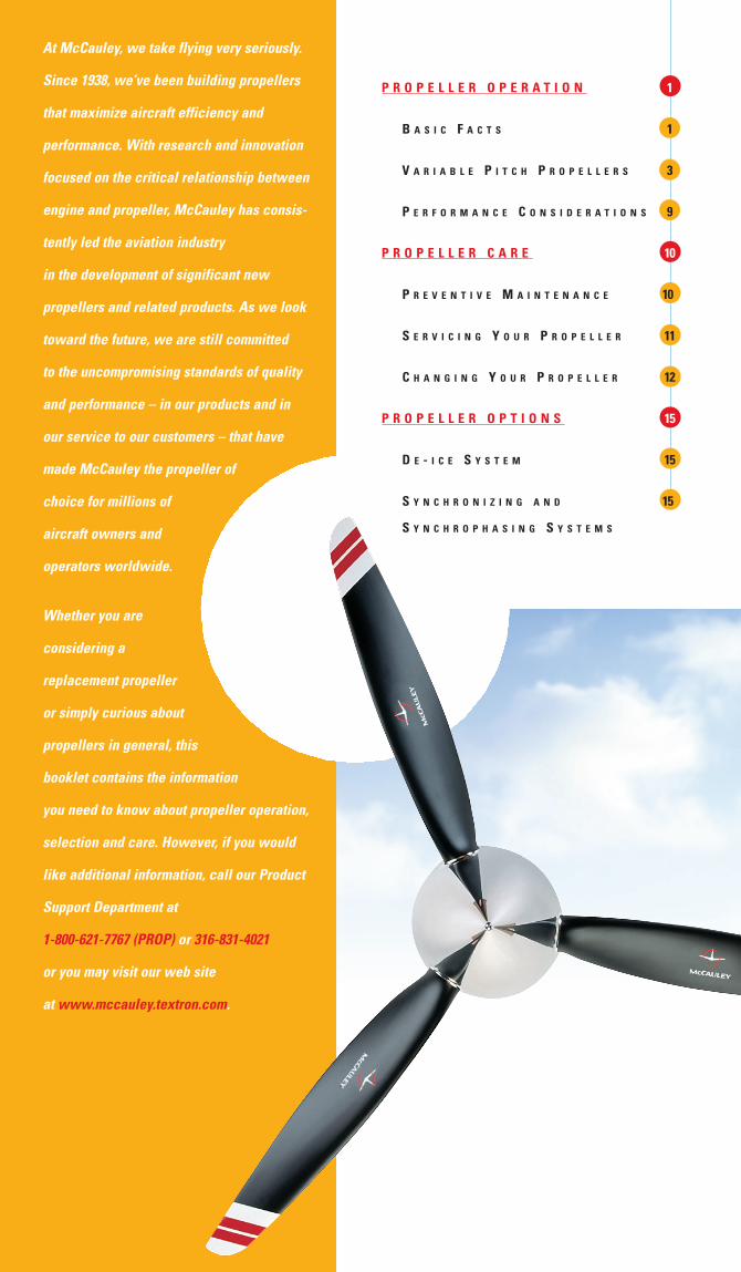
At McCauley, we take flying very seriously.
Since 1938, we’ve been building propellers
that maximize aircraft efficiency and
performance. With research and innovation
focused on the critical relationship between
engine and propeller, McCauley has consis-
tently led the aviation industry
in the development of significant new
propellers and related products. As we look
toward the future, we are still committed
to the uncompromising standards of quality
and performance – in our products and in
our service to our customers – that have
made McCauley the propeller of
choice for millions of
aircraft owners and
operators worldwide.
Whether you are
considering a
replacement propeller
or simply curious about
propellers in general, this
booklet contains the information
you need to know about propeller operation,
selection and care. However, if you would
like additional information, call our Product
Support Department at
1-800-621-7767 (PROP) or 316-831-4021
or you may visit our web site
at www.mccauley.textron.com.
P r o P e l l e r o P e r a t i o n 1
B a s i c F a c t s 1
V a r i a B l e P i t c h P r o P e l l e r s 3
P e r F o r m a n c e c o n s i d e r a t i o n s 9
P r o P e l l e r c a r e 10
P r e V e n t i V e m a i n t e n a n c e 10
s e r V i c i n g Y o u r P r o P e l l e r 11
c h a n g i n g Y o u r P r o P e l l e r 12
P r o P e l l e r o P t i o n S 15
d e - i c e s Y s t e m 15
s Y n c h r o n i z i n g a n d 15
s Y n c h r o P h a s i n g s Y s t e m s
1
vibration; greater flywheel effect and improved
aircraft performance.
McCauley propellers are identified by a model
designation and a serial number. On one-piece,
fixed-pitch props, the serial number is stamped
on the camber side of the hub face. Variable
pitch propellers have separate numbers for
the hub (stamped on the side) and for each
detachable blade (stamped on the butt end of
the blade inside the hub).
t Y P e s o F P r o P e l l e r s
m a n u F a c t u r e d B Y m c c a u l e Y
Propellers are classified according to pitch
configuration. Blade pitch is the angle of the
blades with relation to the plane of rotation
and is a significant variable affecting the
performance of the propeller.
Fixed Pitch: a one-piece prop with a single
fixed blade angle. The pitch (blade angle)
must be high enough to offer good cruis-
ing performance yet low enough to achieve
acceptable takeoff and climb characteristics.
Controllable Pitch: a prop which allows
the adjustment of blades to any desired angle
during flight.
Constant Speed: a prop used with a
governor, that automatically provides constant
RPM by counteracting the forces acting on the
propeller to change the blade angle within a
preset range.
Full-Feathering: a prop which allows blades
to be rotated to a high positive angle to stop
rotation (windmilling) after an engine is shut
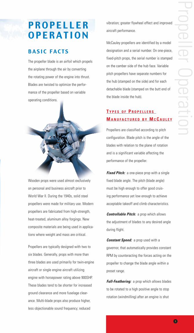
Propeller OperationP R O P E L L E R O P E R A T I O NB A S I C F A C T SThe propeller blade is an airfoil which propels
the airplane through the air by converting
the rotating power of the engine into thrust.
Blades are twisted to optimize the perfor-
mance of the propeller based on variable
operating conditions.
Wooden props were used almost exclusively
on personal and business aircraft prior to
World War II. During the 1940s, solid steel
propellers were made for military use. Modern
propellers are fabricated from high-strength,
heat-treated, aluminum alloy forgings. New
composite materials are being used in applica-
tions where weight and mass are critical.
Propellers are typically designed with two to
six blades. Generally, props with more than
three blades are used primarily for twin-engine
aircraft or single engine aircraft utilizing
engine with horsepower rating above 900SHP.
These blades tend to be shorter for increased
ground clearance and more fuselage clear-
ance. Multi-blade props also produce higher,
less objectionable sound frequency; reduced
2
down, thereby reducing drag and asymmetric
control forces on twin-engine applications.
Reversing: a prop with blades that can be
rotated to a position less than the normal
positive low blade angle setting until a
negative blade angle is obtained, producing
a rearward thrust to slow down, stop or move
the aircraft backward. Typically provided for
turbine installations.
Beta Control: a prop which allows the
manual repositioning of the propeller blade
angle beyond the normal low pitch stop. Used
most often in taxiing, where thrust is manually
controlled by adjusting blade angle with the
power lever. These types of McCauley propellers
are installed exclusively on turbine engines.
c o m m o n t e r m s
Blade: one arm of a propeller from hub to tip.
Hub: center section of the propeller which
carries the blades and is attached to the
engine shaft.
Spinner: a metal cover enclosing the
propeller hub, which improves the appearance
of the propeller and may also streamline
airflow for engine cooling purposes.
Blade tip: the part of the blade furthest from
the hub.
Blade shank: the section of the blade nearest
the hub.
Blade butt: the portion of a blade inside the
hub used to retain the blade.
Blade camber surface: the cambered or
most-cambered side of a blade (visible from
front of the aircraft).
Blade face or thrust surface: the flat side
of a blade (normally visible from the cockpit
of the aircraft).
Blade leading edge: the forward full “cut-
ting” edge of the blade that leads in the
direction of rotation.
Blade trailing edge: the continuous edge
of the blade that trails the leading edge in the
direction of rotation.
Governor: a device, generally mounted on
and driven by the engine, which senses and
controls engine speed (RPM) by hydraulically
adjusting the blade angle of the propeller.
Prop diameter: the diameter of the circle
circumscribed by the blade tips.
Blade station: one of the designated
distances along the blade as measured from
the center of the hub.
Blade thickness: the maximum thickness
between the cambered surface and the face
or thrust surface at a given blade station.
Blade width: the measurement between
the leading edge and the trailing edge at a
given station.
Chord line: a theoretical straight line (per-
pendicular to blade length) drawn between the
leading and trailing edges of the blade.
Blade angle: the angle between the chord
line of a propeller blade section and a plane
perpendicular to the axis of propeller rotation.
Blade angle settings: low and high angle
settings of a controllable-pitch prop – for
feather, reverse, latch and start locks –
which are determined by built-in mechanical
hard stops.
Prop
elle
r Ope
ratio
n
3
V A R I A B L E P I T C H P R O P E L L E R S
F u l l - F e a t h e r i n g V s .
c o n s t a n t s P e e d
A constant-speed (RPM) system permits the
pilot to select the propeller and engine speed
for any situation and automatically maintain
that RPM under varying conditions of aircraft
attitude and engine power. This permits
operation of propeller and engine at the most
efficient RPM and power. RPM is controlled by
varying the pitch of the propeller blades – that
is, the angle of the blades with relation to the
plane of rotation. When the pilot increases
power in flight, the blade angle is increased,
the torque required to spin the propeller is
increased and, for any given RPM setting,
aircraft speed and torque on the engine will
increase. For economy cruising, the pilot can
throttle back to the desired manifold pressure
for cruise conditions and decrease the pitch
of the propeller, while maintaining the pilot-
selected RPM.
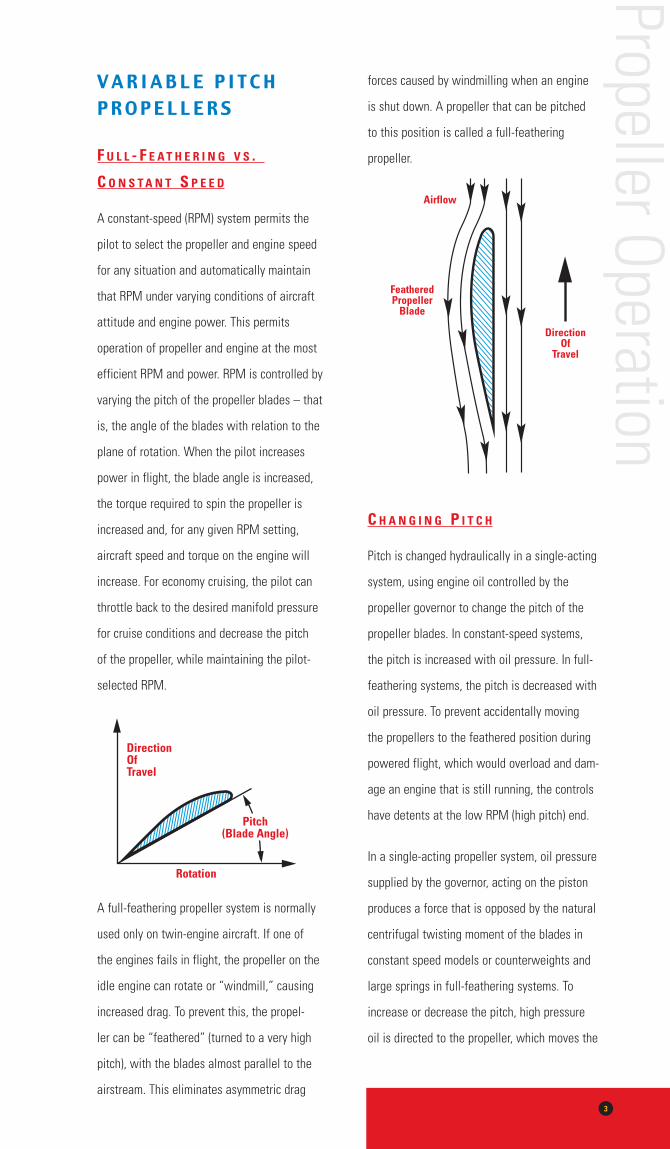
A full-feathering propeller system is normally
used only on twin-engine aircraft. If one of
the engines fails in flight, the propeller on the
idle engine can rotate or “windmill,” causing
increased drag. To prevent this, the propel-
ler can be “feathered” (turned to a very high
pitch), with the blades almost parallel to the
airstream. This eliminates asymmetric drag
forces caused by windmilling when an engine
is shut down. A propeller that can be pitched
to this position is called a full-feathering
propeller.
c h a n g i n g P i t c h
Pitch is changed hydraulically in a single-acting
system, using engine oil controlled by the
propeller governor to change the pitch of the
propeller blades. In constant-speed systems,
the pitch is increased with oil pressure. In full-
feathering systems, the pitch is decreased with
oil pressure. To prevent accidentally moving
the propellers to the feathered position during
powered flight, which would overload and dam-
age an engine that is still running, the controls
have detents at the low RPM (high pitch) end.
In a single-acting propeller system, oil pressure
supplied by the governor, acting on the piston
produces a force that is opposed by the natural
centrifugal twisting moment of the blades in
constant speed models or counterweights and
large springs in full-feathering systems. To
increase or decrease the pitch, high pressure
oil is directed to the propeller, which moves the
Propeller Operation
Directionoftravel
FeatheredPropeller
Blade
Directionof
travel
airflow
Pitch(Blade angle)
rotation
Directionoftravel
FeatheredPropeller
Blade
Directionof
travel
airflow
Pitch(Blade angle)
rotation
4
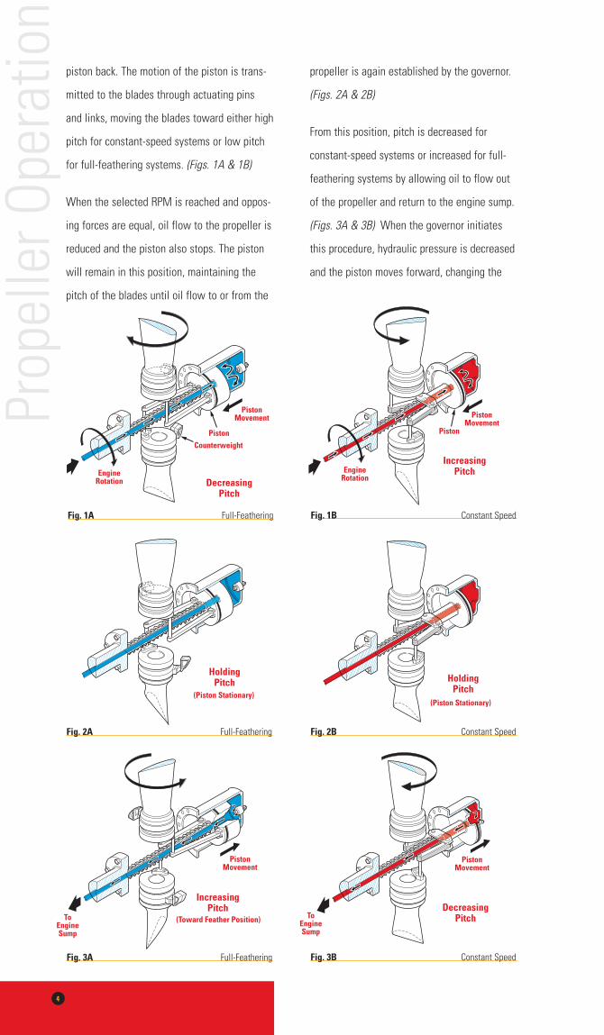
piston back. The motion of the piston is trans-
mitted to the blades through actuating pins
and links, moving the blades toward either high
pitch for constant-speed systems or low pitch
for full-feathering systems. (Figs. 1A & 1B)
When the selected RPM is reached and oppos-
ing forces are equal, oil flow to the propeller is
reduced and the piston also stops. The piston
will remain in this position, maintaining the
pitch of the blades until oil flow to or from the
Prop
elle
r Ope
ratio
npropeller is again established by the governor.
(Figs. 2A & 2B)
From this position, pitch is decreased for
constant-speed systems or increased for full-
feathering systems by allowing oil to flow out
of the propeller and return to the engine sump.
(Figs. 3A & 3B) When the governor initiates
this procedure, hydraulic pressure is decreased
and the piston moves forward, changing the
Piston
DecreasingPitch
enginerotation
counterweight
PistonMovement
Fig. 1a Full-Feathering
increasingPitchengine
rotation
Piston
PistonMovement
Fig. 1B Constant Speed
PistonMovement
increasingPitch
toengineSump
(toward Feather Position)
Fig. 3a Full-Feathering
HoldingPitch
(Piston Stationary)
Fig. 2B Constant Speed
HoldingPitch
(Piston Stationary)
Fig. 2a Full-Feathering
toengineSump
DecreasingPitch
PistonMovement
Fig. 3B Constant Speed
5
pitch of the blades. The piston will continue to
move forward until the selected RPM is reached
and opposing forces are once again equal.
Mechanical stops are installed in the propeller
to limit travel in both the high and low pitch
directions.
F u l l - F e a t h e r i n g a n d
c o n s t a n t - s P e e d g o V e r n i n g
s Y s t e m s
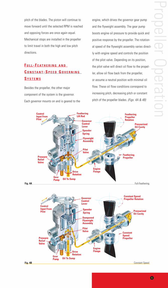
Besides the propeller, the other major
component of the system is the governor.
Each governor mounts on and is geared to the
engine, which drives the governor gear pump
and the flyweight assembly. The gear pump
boosts engine oil pressure to provide quick and
positive response by the propeller. The rotation-
al speed of the flyweight assembly varies direct-
ly with engine speed and controls the position
of the pilot valve. Depending on its position,
the pilot valve will direct oil flow to the propel-
ler, allow oil flow back from the propeller,
or assume a neutral position with minimal oil
flow. These oil flow conditions correspond to
increasing pitch, decreasing pitch or constant
pitch of the propeller blades. (Figs. 4A & 4B)
Propeller Operation
Fig. 4a Full-Feathering
Fig. 4B Constant Speed
6
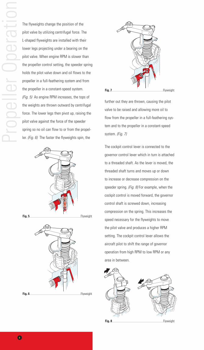
The flyweights change the position of the
pilot valve by utilizing centrifugal force. The
L-shaped flyweights are installed with their
lower legs projecting under a bearing on the
pilot valve. When engine RPM is slower than
the propeller control setting, the speeder spring
holds the pilot valve down and oil flows to the
propeller in a full-feathering system and from
the propeller in a constant-speed system.
(Fig. 5) As engine RPM increases, the tops of
the weights are thrown outward by centrifugal
force. The lower legs then pivot up, raising the
pilot valve against the force of the speeder
spring so no oil can flow to or from the propel-
ler. (Fig. 6) The faster the flyweights spin, the
further out they are thrown, causing the pilot
valve to be raised and allowing more oil to
flow from the propeller in a full-feathering sys-
tem and to the propeller in a constant-speed
system. (Fig. 7)
The cockpit control lever is connected to the
governor control lever which in turn is attached
to a threaded shaft. As the lever is moved, the
threaded shaft turns and moves up or down
to increase or decrease compression on the
speeder spring. (Fig. 8) For example, when the
cockpit control is moved forward, the governor
control shaft is screwed down, increasing
compression on the spring. This increases the
speed necessary for the flyweights to move
the pilot valve and produces a higher RPM
setting. The cockpit control lever allows the
aircraft pilot to shift the range of governor
operation from high RPM to low RPM or any
area in between.
Prop
elle
r Ope
ratio
n
Fig. 5 Flyweight
Fig. 6 Flyweight
Fig. 7 Flyweight
Fig. 8 Flyweight
7
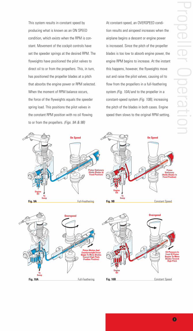
This system results in constant speed by
producing what is known as an ON SPEED
condition, which exists when the RPM is con-
stant. Movement of the cockpit controls have
set the speeder springs at the desired RPM. The
flyweights have positioned the pilot valves to
direct oil to or from the propellers. This, in turn,
has positioned the propeller blades at a pitch
that absorbs the engine power or RPM selected.
When the moment of RPM balance occurs,
the force of the flyweights equals the speeder
spring load. This positions the pilot valves in
the constant RPM position with no oil flowing
to or from the propellers. (Figs. 9A & 9B)
At constant-speed, an OVERSPEED condi-
tion results and airspeed increases when the
airplane begins a descent or engine power
is increased. Since the pitch of the propeller
blades is too low to absorb engine power, the
engine RPM begins to increase. At the instant
this happens, however, the flyweights move
out and raise the pilot valves, causing oil to
flow from the propellers in a full-feathering
system (Fig. 10A) and to the propeller in a
constant-speed system (Fig. 10B), increasing
the pitch of the blades in both cases. Engine
speed then slows to the original RPM setting.
Propeller Operation
toSump
engineoil
on Speed
Piston Stationary(Holds Blades inFixed Position)
Fig. 9a Full-Feathering
toSump
overspeed
Piston Motion andcounterweight Force
Begin to Move Bladestoward High Pitch(Feather Position)
Fig. 10a Full-Feathering
overspeed
engineoil
oil Pressure inFront of Piston
Begins to MoveBlades toward
High Pitch
Fig. 10B Constant Speed
Fig. 9B Constant Speed
on Speed
engineoil
toSump
PistonStationary
(Holds Blades inFixed Position)
8
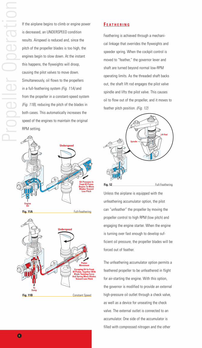
If the airplane begins to climb or engine power
is decreased, an UNDERSPEED condition
results. Airspeed is reduced and, since the
pitch of the propeller blades is too high, the
engines begin to slow down. At the instant
this happens, the flyweights will droop,
causing the pilot valves to move down.
Simultaneously, oil flows to the propellers
in a full-feathering system (Fig. 11A) and
from the propeller in a constant-speed system
(Fig. 11B), reducing the pitch of the blades in
both cases. This automatically increases the
speed of the engines to maintain the original
RPM setting.
F e a t h e r i n g
Feathering is achieved through a mechani-
cal linkage that overrides the flyweights and
speeder spring. When the cockpit control is
moved to “feather,” the governor lever and
shaft are turned beyond normal low-RPM
operating limits. As the threaded shaft backs
out, the shaft lift rod engages the pilot valve
spindle and lifts the pilot valve. This causes
oil to flow out of the propeller, and it moves to
feather pitch position. (Fig. 12)
Unless the airplane is equipped with the
unfeathering accumulator option, the pilot
can “unfeather” the propeller by moving the
propeller control to high RPM (low pitch) and
engaging the engine starter. When the engine
is turning over fast enough to develop suf-
ficient oil pressure, the propeller blades will be
forced out of feather.
The unfeathering accumulator option permits a
feathered propeller to be unfeathered in flight
for air-starting the engine. With this option,
the governor is modified to provide an external
high-pressure oil outlet through a check valve,
as well as a device for unseating the check
valve. The external outlet is connected to an
accumulator. One side of the accumulator is
filled with compressed nitrogen and the other
Prop
elle
r Ope
ratio
n
engineoil
underspeed
oil Pressure inFront of Piston
Begins to MoveBlades toward
low Pitch
underspeed
toSump
PistonMovement
escaping oil in Frontof Piston, together With
Blade twisting Forceand Spring Move Blades
toward low Pitch
Fig. 11a Full-Feathering
Fig. 11B Constant Speed
Spindle
lift rod
Fig. 12 Full-Feathering
9
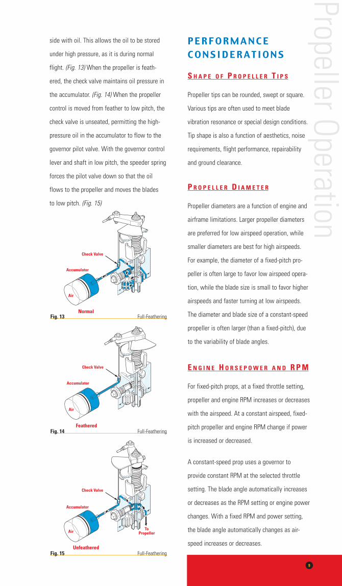
side with oil. This allows the oil to be stored
under high pressure, as it is during normal
flight. (Fig. 13) When the propeller is feath-
ered, the check valve maintains oil pressure in
the accumulator. (Fig. 14) When the propeller
control is moved from feather to low pitch, the
check valve is unseated, permitting the high-
pressure oil in the accumulator to flow to the
governor pilot valve. With the governor control
lever and shaft in low pitch, the speeder spring
forces the pilot valve down so that the oil
flows to the propeller and moves the blades
to low pitch. (Fig. 15)
P E R F O R M A N C E C O N S I D E R A T I O N S
s h a P e o F P r o P e l l e r t i P s
Propeller tips can be rounded, swept or square.
Various tips are often used to meet blade
vibration resonance or special design conditions.
Tip shape is also a function of aesthetics, noise
requirements, flight performance, repairability
and ground clearance.
P r o P e l l e r d i a m e t e r
Propeller diameters are a function of engine and
airframe limitations. Larger propeller diameters
are preferred for low airspeed operation, while
smaller diameters are best for high airspeeds.
For example, the diameter of a fixed-pitch pro-
peller is often large to favor low airspeed opera-
tion, while the blade size is small to favor higher
airspeeds and faster turning at low airspeeds.
The diameter and blade size of a constant-speed
propeller is often larger (than a fixed-pitch), due
to the variability of blade angles.
e n g i n e h o r s e P o w e r a n d r P m
For fixed-pitch props, at a fixed throttle setting,
propeller and engine RPM increases or decreases
with the airspeed. At a constant airspeed, fixed-
pitch propeller and engine RPM change if power
is increased or decreased.
A constant-speed prop uses a governor to
provide constant RPM at the selected throttle
setting. The blade angle automatically increases
or decreases as the RPM setting or engine power
changes. With a fixed RPM and power setting,
the blade angle automatically changes as air-
speed increases or decreases.
Propeller Operation
accumulator
normal
check Valve
air
accumulator
Feathered
check Valve
air
accumulator
unfeathered
toPropeller
check Valve
air
Fig. 13 Full-Feathering
Fig. 14 Full-Feathering
Fig. 15 Full-Feathering
10
P R O P E L L E R C A R EP R E V E N T I V E M A I N T E N A N C E
V i s u a l i n s P e c t i o n s
Prop blades should be visually inspected
regularly, preferably before each flight. Look
for surface damage and irregularities such as
dents, nicks or scratches. These imperfections
should be dressed out by an A&P mechanic
before cracks have a chance to develop.
Minor repairs should not impair propeller
performance.
If you have a spinner, check external surfaces
for damage and the attachment parts for
normal tightness. If no spinner is installed,
visually examine the front and back surfaces
of the propeller hub and its attachment onto
the engine shaft for normal tightness.
At least once a year (for one-piece, fixed-pitch
propellers) or every 100 flight hours (for all
other types of props), inspect every inch of
the prop in the best possible light, looking for
any evidence of damage. Have an approved,
FAA-licensed A&P mechanic remove the spin-
ner (if installed) and have the propeller instal-
lation bolts checked for tightness with a
torque wrench.
P r e V e n t i n g d a m a g e
High-speed operation of the propeller when
standing or taxiing over dirt, gravel or loose
stone can cause nicks and other damage
to blades.
Never use prop blades as handles to maneuver
a plane on the ground. Either use a tow bar on
your plane’s steerable nose wheel, or use the
areas of the airframe designated by the manu-
facturer as safe for push/pull pressure. Pulling
or pushing with the propeller could severely
damage actuating components inside the hub.
c l e a n i n g t h e P r o P
Use a clean cloth dampened with light oil to
wipe the prop after each flight, or as regularly
as possible, especially if you operate near salt
water or fly a sea plane. The oil removes and
repels substances that cause corrosion and
helps prevent water erosion. Never scrape the
blades, use abrasive cleaners or use water
to clean the propeller or hub. Forcing water
into the hub can lead to corrosion or lubricant
breakdown. If waxing the blade camber side,
wipe first with a non-oil base solvent.
r e P a i n t i n g P r o P B l a d e s
If repainting is required, use non-reflective
black for the side of the blades which face
the pilot, so that the spinning propeller is not
seen as a shiny, hypnotic disc. Paint blade tips
on the opposite side (face side) with bright
colors so that the spinning propeller can be
more easily seen by people walking near it
on the ground.
Prop
elle
r Car
e
S E R V I C I N G Y O U R P R O P E L L E R
l o c a t i n g Q u a l i F i e d
P r o P e l l e r s e r V i c e
t e c h n i c i a n s
All service on your propeller should be per-
formed by an approved propeller repair station
that is certified by the Federal Aviation Agency
to service, recondition, repair or overhaul pro-
pellers in accordance with the requirements
established by the propeller manufacturer or
the FAA. Approved repair stations have
demonstrated that they have the equipment,
technical information and skills to perform
this work. They are licensed and limited to
working only on specified propeller models,
which are listed by manufacturer and model
on their authorization.
Know where your “home base” prop repair
station is located, as well as other stations
in areas where you fly and land frequently. If
you are repairing or overhauling your propeller,
upgrading your aircraft or simply replacing one
propeller with another just like it, contact us
for a list of McCauley Authorized Propeller
Sales and Service Centers. FAR’s require that
you maintain a separate log for the propeller
so that you have a permanent record of prop
maintenance and overhaul.
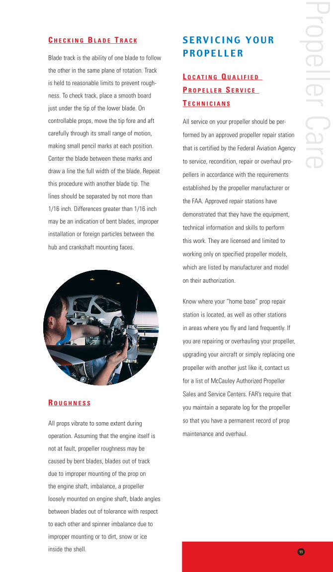
c h e c k i n g B l a d e t r a c k
Blade track is the ability of one blade to follow
the other in the same plane of rotation. Track
is held to reasonable limits to prevent rough-
ness. To check track, place a smooth board
just under the tip of the lower blade. On
controllable props, move the tip fore and aft
carefully through its small range of motion,
making small pencil marks at each position.
Center the blade between these marks and
draw a line the full width of the blade. Repeat
this procedure with another blade tip. The
lines should be separated by not more than
1/16 inch. Differences greater than 1/16 inch
may be an indication of bent blades, improper
installation or foreign particles between the
hub and crankshaft mounting faces.
r o u g h n e s s
All props vibrate to some extent during
operation. Assuming that the engine itself is
not at fault, propeller roughness may be
caused by bent blades, blades out of track
due to improper mounting of the prop on
the engine shaft, imbalance, a propeller
loosely mounted on engine shaft, blade angles
between blades out of tolerance with respect
to each other and spinner imbalance due to
improper mounting or to dirt, snow or ice
inside the shell. 11
Propeller Care
12
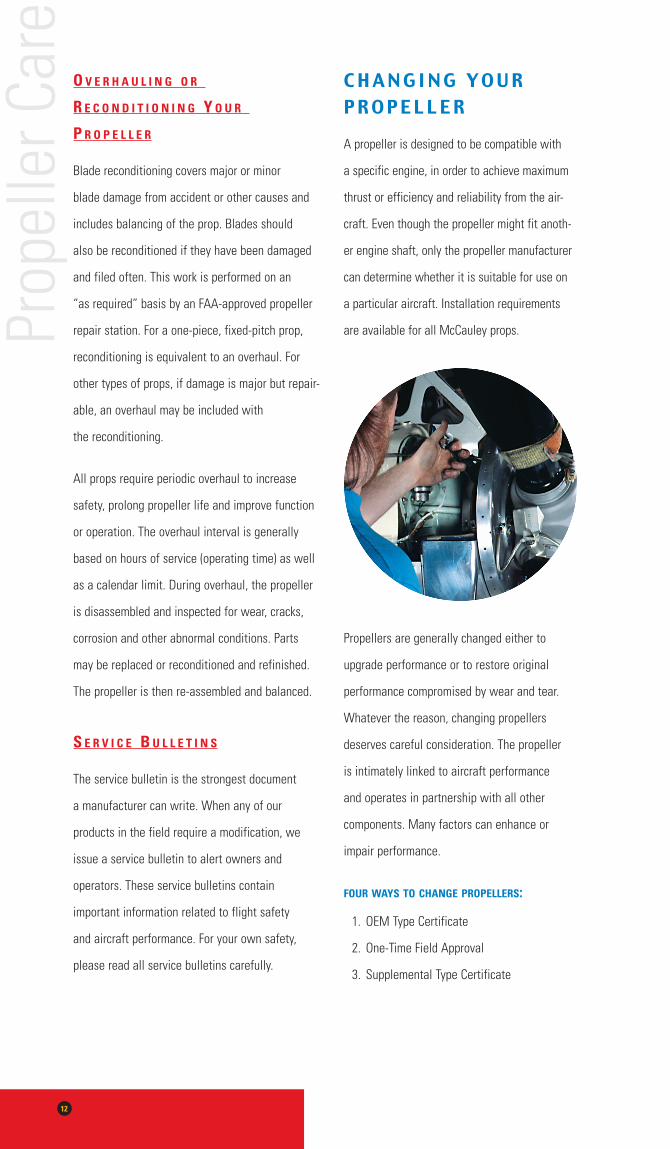
o V e r h a u l i n g o r
r e c o n d i t i o n i n g Y o u r
P r o P e l l e r
Blade reconditioning covers major or minor
blade damage from accident or other causes and
includes balancing of the prop. Blades should
also be reconditioned if they have been damaged
and filed often. This work is performed on an
“as required” basis by an FAA-approved propeller
repair station. For a one-piece, fixed-pitch prop,
reconditioning is equivalent to an overhaul. For
other types of props, if damage is major but repair-
able, an overhaul may be included with
the reconditioning.
All props require periodic overhaul to increase
safety, prolong propeller life and improve function
or operation. The overhaul interval is generally
based on hours of service (operating time) as well
as a calendar limit. During overhaul, the propeller
is disassembled and inspected for wear, cracks,
corrosion and other abnormal conditions. Parts
may be replaced or reconditioned and refinished.
The propeller is then re-assembled and balanced.
s e r V i c e B u l l e t i n s
The service bulletin is the strongest document
a manufacturer can write. When any of our
products in the field require a modification, we
issue a service bulletin to alert owners and
operators. These service bulletins contain
important information related to flight safety
and aircraft performance. For your own safety,
please read all service bulletins carefully.
C H A N G I N G Y O U R P R O P E L L E R
A propeller is designed to be compatible with
a specific engine, in order to achieve maximum
thrust or efficiency and reliability from the air-
craft. Even though the propeller might fit anoth-
er engine shaft, only the propeller manufacturer
can determine whether it is suitable for use on
a particular aircraft. Installation requirements
are available for all McCauley props.
Propellers are generally changed either to
upgrade performance or to restore original
performance compromised by wear and tear.
Whatever the reason, changing propellers
deserves careful consideration. The propeller
is intimately linked to aircraft performance
and operates in partnership with all other
components. Many factors can enhance or
impair performance.
FourwaYstochangeProPellers:
1. OEM Type Certificate
2. One-Time Field Approval
3. Supplemental Type Certificate
Prop
elle
r Car
e
13
o e m t Y P e c e r t i F i c a t e
Any propeller that appears on the Original
Equipment Manufacturer’s (OEM) approved
equipment list, on the Aircraft Type Certificate
Data Sheet, is automatically approved for that
application. No further paperwork is required.
o n e - t i m e F i e l d a P P r o V a l
More subjective in nature, the One-time Field
Approval changes for every situation and is
heavily dependent on the personality and
experience of the FAA representative. In
general, the more reasonable the request,
the more likely it is to be granted. There are
only two things for certain about the One-time
Field Approval:
• It requires the endorsement of the FAA
• It has to have some degree of technical
justification
s u P P l e m e n t a l t Y P e
c e r t i F i c a t e ( s t c )
The FAA issues an STC for propellers that
have passed rigorous and extensive testing but
which are not listed on the OEM’s approved
equipment list for a particular aircraft. The
STC is the easiest way to modify an existing
airplane in the field. Most owners, operators
and mechanics who wish to upgrade propeller
performance will use STCs.
Single-component STCs involve a specific
propeller that has been approved for a specific
aircraft. For example, the single-component
STC is commonly used to upgrade an aircraft
from a two-bladed to a three-bladed propeller.
It may also be used by owners or operators
who are not satisfied with the performance
of their original propeller.
The combination STC involves multiple
components, such as a propeller and an engine
upgrade. Although less common than single-
component STCs, the combination STC is
gaining popularity because of the integral
relationship between propeller and engine.
The STC holder may be the original propeller
manufacturer, the original aircraft manufac-
turer or an individual. To obtain an STC, the
STC applicant often works with the FAA and
the OEM, tests and evaluates the propeller,
and pays for flight performance testing and
stress surveys. Developing the STC for a sim-
ple, one-propeller changeover for a particular
aircraft can be a significant expense.
When someone other than McCauley obtains
an STC with a McCauley product, the prop
is usually sold directly to the STC holder for
delivery to the end user. However:
• STC holders do not always work with the
original propeller manufacturer prior to
obtaining STC approval from the FAA.
STC holders who have not worked with
McCauley may not fully understand our
Propeller Care
14
products, their applications and how they
are likely to perform on specific aircraft.
• The FAA usually does not notify the origi-
nal propeller manufacturer when it grants
an STC to someone other than the OEM.
As a result, we have no way of knowing
about all STCs approved for our propellers
by the FAA.
• STC holders who do not work with
McCauley while obtaining an STC for our
products often neglect to inform us when
the STC is granted.
Therefore, always contact the manufacturer of
the STC propeller you plan to install, and ask if
the OEM is aware of the STC or of any poten-
tial problems. Also, contact the STC holder
directly to discuss the performance changes
you should expect. Request a list of owners
who have performed similar installations.
Make sure everything is working properly
under usual operating conditions before install-
ing any STC conversion. To determine whether
or not a problem is propeller related, use the
process of elimination, changing one variable
at a time. For example, a recently overhauled
engine may cause vibration,
which could be mistakenly blamed on a new
propeller installed at the same time. If you con-
verted from a two-bladed propeller to a three-
bladed propeller immediately after an engine
overhaul, try out the overhauled engine using
the two-bladed propeller. If you experience
vibration that was not apparent before the
overhaul, you will know that it is an engine
problem, not a propeller problem.
The warranty that comes with the STC
conversion covers the propeller assembly.
Technically, the original propeller manufac-
turer is responsible only if the propeller is
defective. The STC holder is responsible
for problems with installation adjustments.
However, owners and operators may have
adjustment or performance trouble that is
not propeller-related, including problems
with the engine, engine mounts, cowling
configuration or airframe. As a result, perfor-
mance varies by individual aircraft.
Prop
elle
r Car
e
15
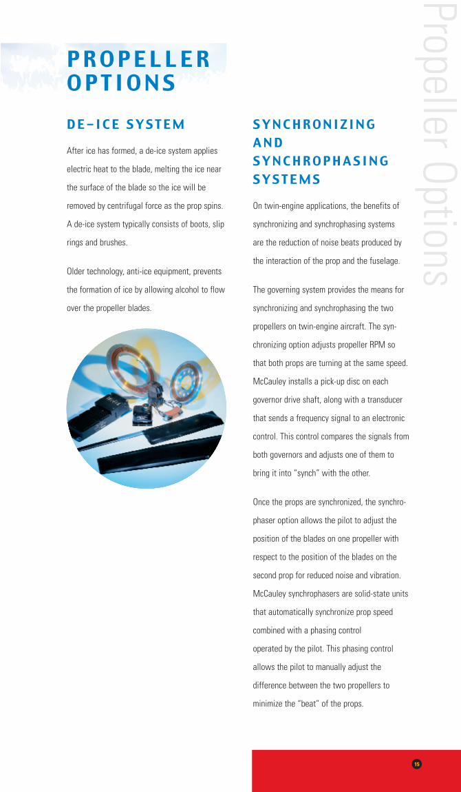
P R O P E L L E R O P T I O N SD E - I C E S Y S T E M
After ice has formed, a de-ice system applies
electric heat to the blade, melting the ice near
the surface of the blade so the ice will be
removed by centrifugal force as the prop spins.
A de-ice system typically consists of boots, slip
rings and brushes.
Older technology, anti-ice equipment, prevents
the formation of ice by allowing alcohol to flow
over the propeller blades.
S Y N C H R O N I z I N G A N D S Y N C H R O P H A S I N G S Y S T E M S
On twin-engine applications, the benefits of
synchronizing and synchrophasing systems
are the reduction of noise beats produced by
the interaction of the prop and the fuselage.
The governing system provides the means for
synchronizing and synchrophasing the two
propellers on twin-engine aircraft. The syn-
chronizing option adjusts propeller RPM so
that both props are turning at the same speed.
McCauley installs a pick-up disc on each
governor drive shaft, along with a transducer
that sends a frequency signal to an electronic
control. This control compares the signals from
both governors and adjusts one of them to
bring it into “synch” with the other.
Once the props are synchronized, the synchro-
phaser option allows the pilot to adjust the
position of the blades on one propeller with
respect to the position of the blades on the
second prop for reduced noise and vibration.
McCauley synchrophasers are solid-state units
that automatically synchronize prop speed
combined with a phasing control
operated by the pilot. This phasing control
allows the pilot to manually adjust the
difference between the two propellers to
minimize the “beat” of the props.
Propeller Options
16
A b o u t M c C a u l e yMcCauley is the world’s largest full-line
manufacturer of propellers for the regional
airline, corporate and personal aviation mar-
kets. With over 60 years of design and manu-
facturing experience, McCauley continues to
be a pioneer in the general aviation industry.
McCauley propellers are standard equip-
ment on aircraft worldwide such as: British
Aerospace, Cessna, Commander, Fairchild,
Maule, Mooney, Piper, Raytheon and others,
as well as aircraft kit manufacturers. Make
McCauley your choice as well.
While this booklet was meant to provide
only a small overview of McCauley propellers
and propeller components – their operation,
performance and proper maintenance, we
hope you have found it both helpful and
informative. If you have further questions or
concerns, please feel free to contact our
Sales or Product Support Department at
1-800-621-7767 (ProP) or visit our web site:
www.mccauley.txtav.com.
Abou
t McC
aule
y

N o t e s
________________________________________________________
________________________________________________________
________________________________________________________
________________________________________________________
________________________________________________________
________________________________________________________
________________________________________________________
________________________________________________________
________________________________________________________
________________________________________________________
________________________________________________________
________________________________________________________
________________________________________________________
________________________________________________________
________________________________________________________
________________________________________________________
________________________________________________________
________________________________________________________
________________________________________________________
________________________________________________________

800-621-7767 (PROP)316-831-4021
FOR THE DEALER NEAREST YOU
www.mccauley.txtav.com