Embed Size (px)
Citation preview
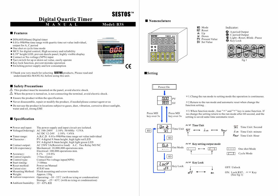
Digital Quartic Timer
DIN(48X48mm) Digital timer0.01s-99h99m time range with quartic time set value individual,output for A, C period
MCU for digital control, High accuracy and reliability0.39" height LED, prevent dazzle panel, highly visible displayContact or No-voltage (NPN) inputTact switch for up or down set value, easily operateKey lock function, prevent mistake operationSwitching power supply and low consumption
One shot or cycle time mode
Out Mode
Key setting output mode
Key Lock
SESTOSTM
SESTOSTM
A
TIMER
Q
B3S
MD
RST
PV
SVC
M A N U A L Model: B3S
Features
Thank you very much for selecting products, Please read andunderstand this MANUAL before using this unit.
SESTOS
Safety Precautions
This product must be mounted on the panel, avoid electric shock.
When the power is turned on, is not connecting the terminal, avoid electric shock.
Ensure the product within the specification.
Never disassemble, repair or modify the product, if needed please contact agent or us
Do not use the product in locations subject to gases, dust, vibration, corrosive direct sunlight,water and oil, strong EMI
Power and input:Voltage(Ordering):
Character :
Contact output:Life expectancy:
Accuracy:Control signals:Control type:Start timing:Reset method:Cutout size:Mounting Method:Weight:
Timer range:
Ambient temperature:
Ambient humidity:
The power supply and input circuit are isolated.AC 100-240V 10% 50/60Hz 5VAAC/DC 12-24V 10% 4VAA,B,C,D 0.01s-99h99m time range set value individual
AC 250V 3A(Resistive load) A.C. Two Relay NO/NCMechanical: 10,000,000 operations min.Electrical: 100,000 operations min.0.1% 0.05s
5ms (Gate)Contact/No-voltage input(NPN)
100msPower on/Manual45X45 mmFlush mounting and screw terminalsApprox.130gOperating: -10 55 (with no icing or condensation)Storage: -25 65 (with no icing or condensation)35 85% RH
PV: 4 digital 9.9mm height, high light red LEDSV: 4 digital 8.0mm height, high light green LED
Nomenclature
A
C
Q
Indicator:
: A period Output: C period Output: Light--Reset; Blink--Pause: Key Lock
MD
RST
PV
SV
:Mode:Reset:Up:Down:Present Value:Set Value
Setting
Power On
PV
SV
Press MDkey over 3s
Press MDkey over 3s
1.Chang the run mode to setting mode the operation is continuous.
2.Return to the run mode and automatic reset when change thefunction setting .
3.When function mode , four " " and " " key is same function. Ifno change the setting return to the run mode after 60 second, and the
setting is saved same time automatic reset.
Time Unit
Key Lock
Time UnitTime Unit: Second
Time Unit: minute
Time Unit: Hour
One shot Mode
Cycle Mode
OFF: Unlock
ON: Lock RST Key
Specification
MD
RST
fig 1
(See fig 1)
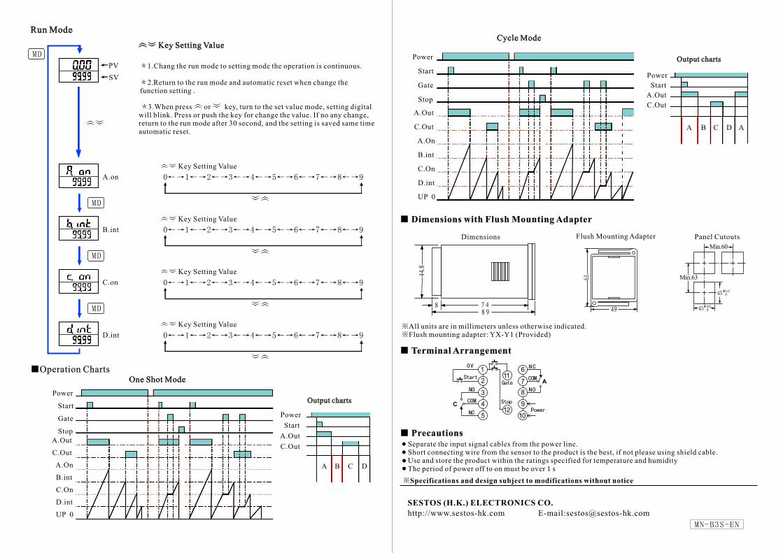
Run Mode
PV
SV
A.on
B.int
C.on
D.int
Key Setting Value
Key Setting Value
Key Setting Value
Key Setting Value
Key Setting Value
One Shot Mode
A.Out
C.Out
A.On
B.int
C.On
D.int
UP 0
Power
Start
Gate
Stop
Output charts
Power
Start
A.Out
C.Out
A B C D
A.Out
C.Out
A.On
B.int
C.On
D.int
UP 0
Power
Start
Gate
Stop
Cycle Mode
Output charts
A B C
Power
Start
A.Out
C.Out
D A
1.Chang the run mode to setting mode the operation is continuous.
2.Return to the run mode and automatic reset when change thefunction setting .
3.When press or key, turn to the set value mode, setting digitalwill blink. Press or push the key for change the value. If no any change,return to the run mode after 30 second, and the setting is saved same timeautomatic reset.
Operation Charts
Dimensions with Flush Mounting Adapter
Dimensions Panel CutoutsFlush Mounting Adapter
Min.63
Min.60
All units are in millimeters unless otherwise indicated.Flush mounting adapter: YX-Y1 (Provided)
Terminal Arrangement
10
6
7
8
9
111
12
2
3
4
5
A
C
Precautions
Separate the input signal cables from the power line.Short connecting wire from the sensor to the product is the best, if not please using shield cable.Use and store the product within the ratings specified for temperature and humidityThe period of power off to on must be over 1 s
Specifications and design subject to modifications without notice
SESTOS (H.K.) ELECTRONICS CO.
http://www.sestos-hk.com E-mail:[email protected]